JP2011056683A - Decorative sheet, method for manufacturing the same, and decorative article - Google Patents
Decorative sheet, method for manufacturing the same, and decorative article Download PDFInfo
- Publication number
- JP2011056683A JP2011056683A JP2009205974A JP2009205974A JP2011056683A JP 2011056683 A JP2011056683 A JP 2011056683A JP 2009205974 A JP2009205974 A JP 2009205974A JP 2009205974 A JP2009205974 A JP 2009205974A JP 2011056683 A JP2011056683 A JP 2011056683A
- Authority
- JP
- Japan
- Prior art keywords
- film layer
- glossy film
- metallic
- layer
- metallic glossy
- Prior art date
- Legal status (The legal status is an assumption and is not a legal conclusion. Google has not performed a legal analysis and makes no representation as to the accuracy of the status listed.)
- Withdrawn
Links
Images


Landscapes
- Decoration By Transfer Pictures (AREA)
- Laminated Bodies (AREA)
- Injection Moulding Of Plastics Or The Like (AREA)
Abstract
Description
本発明は、基体シート上に金属光沢膜層を含む転写層が形成された加飾シート及びその製造方法、並びに当該加飾シートにより加飾された加飾品に関する。 The present invention relates to a decorative sheet in which a transfer layer including a metallic gloss film layer is formed on a base sheet, a method for producing the decorative sheet, and a decorative product decorated with the decorative sheet.
従来から、物品表面を装飾(加飾)するのに加飾シートが用いられている。加飾シートは、基体シート上に、剥離層、柄層、接着層などで構成される転写層を設けたものである。加飾シートにより物品表面を装飾する方法としては、転写法が知られている。転写法とは、加飾シートを加熱加圧して転写層を物品表面に密着させた後、基体シートを剥離して、物品表面に転写層のみを転移して装飾を行う方法である。また、物品が携帯電話やパーソナルコンピュータの筐体などに用いられる樹脂成形品である場合に、転写法をより合理的に行う方法として、成形同時加飾法が知られている。成形同時加飾法とは、加飾シートを金型のキャビティ内に配置した状態で金型内に挟み込み、当該金型内に溶融樹脂を射出したのち適宜冷却して樹脂成形品を得るのと同時に、当該樹脂成形品の表面に加飾シートを接着したのち基体シートを剥離して、樹脂成形品の表面に装飾を行う方法である。 Conventionally, a decorative sheet has been used to decorate (decorate) an article surface. The decorative sheet is a base sheet provided with a transfer layer composed of a release layer, a handle layer, an adhesive layer, and the like. As a method for decorating the surface of an article with a decorative sheet, a transfer method is known. The transfer method is a method in which the decorative sheet is heated and pressed to bring the transfer layer into close contact with the article surface, then the base sheet is peeled off, and only the transfer layer is transferred to the article surface for decoration. In addition, when the article is a resin molded product used for a cellular phone or a personal computer casing, a simultaneous molding and decorating method is known as a method for performing the transfer method more rationally. The simultaneous molding decoration method is to insert a decorative sheet in a mold cavity in a state of being placed in a mold cavity, inject a molten resin into the mold, and then cool appropriately to obtain a resin molded product. At the same time, after the decorative sheet is bonded to the surface of the resin molded product, the base sheet is peeled off to decorate the surface of the resin molded product.
近年、携帯電話やパーソナルコンピュータの筐体などに用いられる樹脂成形品においては、デザインの嗜好が多様化しており、様々なデザインのものが求められている。その要望に応える加飾シートとして、金属光沢膜層を備えた加飾シートがある。この加飾シートを用いて成形同時加飾法を行うことにより、樹脂成形品の表面に金属光沢を付与することができる。このような加飾シートとしては、例えば、特許文献1(特開2002−200700号公報)、特許文献2(特開2009−6613号公報)などに記載されたものがある。 In recent years, resin molded products used for mobile phones, personal computer housings, and the like have diversified design preferences, and various designs are required. As a decorative sheet that meets the demand, there is a decorative sheet having a metallic gloss film layer. By performing the simultaneous molding decoration method using this decorative sheet, a metallic luster can be imparted to the surface of the resin molded product. Examples of such a decorative sheet include those described in Patent Document 1 (Japanese Patent Laid-Open No. 2002-200700), Patent Document 2 (Japanese Patent Laid-Open No. 2009-6613), and the like.
特許文献1には、基体シートと金属光沢膜層との間の密着力を向上させるため、金属光沢膜層を2層構造とし、基体シート側の第1金属光沢膜層を、基体シートと結合し易く且つ第2金属光沢膜層とで合金層を形成できるような金属材料で構成した加飾シートが記載されている。
In
特許文献2には、立ち上がり形状の大きい箇所でもクラックが発生せず、バックライトで照光しても光漏れが発生しないようにするため、2つの金属光沢膜層を互いに重ならないように形成した加飾シートが開示されている。
In
加飾シートにおいて、互いに隣接する層の密着性を向上させるには、それらの間にアンカー層を設けることが一般的である。このアンカー層は、通常、グラビア印刷などの印刷法により形成される。この印刷法によりアンカー層を形成した場合、アンカー層の表面は凹凸形状になる。このため、この凹凸形状のアンカー層の表面に金属光沢膜層を形成した場合、その界面は凹凸形状になる。すなわち、金属光沢膜層の表面が凹凸形状になる。 In the decorative sheet, in order to improve the adhesion between adjacent layers, it is common to provide an anchor layer between them. This anchor layer is usually formed by a printing method such as gravure printing. When the anchor layer is formed by this printing method, the surface of the anchor layer becomes uneven. For this reason, when a metallic luster film layer is formed on the surface of the uneven anchor layer, the interface becomes uneven. That is, the surface of the metallic gloss film layer has an uneven shape.
このような構成を有する加飾シートにアンカー層側から金属光沢膜層の凹凸形状の表面に光(可視光)が入射した場合、その入射光は、金属光沢膜層の凹部及び凸部で反射される。このとき、凹部で反射される光と凸部で反射される光とでは光路長が異なるため、光路差が生じる。この光路差により、反射光同士が基体シートの表面部分で互いに干渉し合い、基体シートの表面部分に干渉縞が発生する。この干渉縞は、加飾シートにより加飾された加飾品の美観を低下させる一因となる。 When light (visible light) is incident on the uneven surface of the metallic glossy film layer from the anchor layer side to the decorative sheet having such a configuration, the incident light is reflected by the concave and convex portions of the metallic glossy film layer. Is done. At this time, since the optical path length differs between the light reflected by the concave portion and the light reflected by the convex portion, an optical path difference occurs. Due to this optical path difference, the reflected lights interfere with each other at the surface portion of the base sheet, and interference fringes are generated at the surface portion of the base sheet. This interference fringe becomes a cause of deteriorating the beauty of the decorative product decorated by the decorative sheet.
従って、本発明の目的は、前記課題を解決することにあって、基体シートの表面部分に干渉縞が発生することを抑制することができる加飾シート及びその製造方法、並びに、当該加飾シートにより加飾された加飾品を提供することにある。 Accordingly, an object of the present invention is to solve the above-described problem, and to provide a decorative sheet that can suppress the occurrence of interference fringes on the surface portion of the base sheet, a method for manufacturing the decorative sheet, and the decorative sheet It is to provide a decorative product decorated by the above.
前記目的を達成するために、本発明は以下のように構成する。
本発明の第1態様によれば、基体シート上に少なくとも第1金属光沢膜層と第2金属光沢膜層とを含む転写層が形成された加飾シートであって、
前記第1金属光沢膜層は、光透過性を有し、前記基体シート側の表面が凹凸形状に形成され、
前記第2金属光沢膜層は、光反射性を有し、前記第1金属光沢膜層の前記基体シート側とは反対側の表面に隣接して設けられ、前記第1金属光沢膜層との界面が平坦である、加飾シートを提供する。
In order to achieve the above object, the present invention is configured as follows.
According to the first aspect of the present invention, there is provided a decorative sheet in which a transfer layer including at least a first metallic glossy film layer and a second metallic glossy film layer is formed on a base sheet,
The first metallic glossy film layer has light transmittance, and the surface on the base sheet side is formed in an uneven shape,
The second metallic glossy film layer has light reflectivity and is provided adjacent to a surface of the first metal glossy film layer opposite to the base sheet side, A decorative sheet having a flat interface is provided.
本発明の第2態様によれば、前記第1金属光沢膜層の光透過率は、5%以上70%以下である、第1態様に記載の加飾シートを提供する。 According to a second aspect of the present invention, there is provided the decorative sheet according to the first aspect, wherein the light transmittance of the first metallic glossy film layer is 5% or more and 70% or less.
本発明の第3態様によれば、前記第1金属光沢膜層は、前記第2金属光沢膜層を構成する金属材料よりも酸化還元電位が0.05V以上高い金属材料で構成されている、第1又は2態様に記載の加飾シートを提供する。 According to the third aspect of the present invention, the first metallic glossy film layer is made of a metal material having a redox potential higher by 0.05 V or more than the metal material constituting the second metal glossy film layer. A decorative sheet according to the first or second aspect is provided.
本発明の第4態様によれば、前記第1金属光沢膜層は、前記第2金属光沢膜層を構成する金属材料よりも酸化還元電位が0.1V以上高い金属材料で構成されている、第1又は2態様に記載の加飾シートを提供する。 According to the fourth aspect of the present invention, the first metallic glossy film layer is made of a metal material having a redox potential higher by 0.1 V or more than the metal material constituting the second metal glossy film layer. A decorative sheet according to the first or second aspect is provided.
本発明の第5態様によれば、前記第1金属光沢膜層の前記基体シート側の表面には、塩素を含む樹脂材料で構成されたアンカー層が設けられている、第3又は4態様に記載の加飾シートを提供する。 According to a fifth aspect of the present invention, in the third or fourth aspect, an anchor layer made of a resin material containing chlorine is provided on the surface of the first metallic glossy film layer on the base sheet side. Provide the decorative sheet described.
本発明の第6態様によれば、前記第2金属光沢膜層は、前記第1金属光沢膜層の前記基体シートとは反対側の表面上に部分的に形成されている、第1〜5態様のいずれか1つに記載の加飾シートを提供する。 According to the 6th aspect of this invention, the said 2nd metallic glossy film layer is partially formed on the surface on the opposite side to the said base sheet of the said 1st metallic glossy film layer, the 1st-5th A decorative sheet according to any one of the aspects is provided.
本発明の第7態様によれば、前記第2金属光沢膜上にはレジスト層が形成されている、第1〜5態様のいずれか1つに記載の加飾シートを提供する。 According to a seventh aspect of the present invention, there is provided the decorative sheet according to any one of the first to fifth aspects, wherein a resist layer is formed on the second metallic gloss film.
本発明の第8態様によれば、前記第1金属光沢膜層は、島状構造を有する、第1〜7態様のいずれか1つに記載の加飾シートを提供する。 According to the 8th aspect of this invention, the said 1st metallic glossy film layer provides the decorating sheet as described in any one of the 1st-7th aspect which has an island-like structure.
本発明の第9態様によれば、前記第1金属光沢膜層は、スズ、インジウム、又は亜鉛により構成されている、第8態様に記載の加飾シートを提供する。 According to a ninth aspect of the present invention, there is provided the decorative sheet according to the eighth aspect, wherein the first metallic glossy film layer is composed of tin, indium, or zinc.
本発明の第10態様によれば、第6又は7態様に記載の加飾シートにより加飾された加飾品であって、
前記第1金属光沢膜層は、島状構造を有するように構成され、
前記第1金属光沢膜層の前記第2金属光沢膜層が設けられていない領域と対向するようにアンテナが設けられている、加飾品を提供する。
According to the tenth aspect of the present invention, there is a decorative product decorated with the decorative sheet according to the sixth or seventh aspect,
The first metallic gloss film layer is configured to have an island structure,
Provided is a decorative product in which an antenna is provided so as to face a region of the first metal glossy film layer where the second metal glossy film layer is not provided.
本発明の第11態様によれば、基体シート上に少なくとも第1金属光沢膜層と第2金属光沢膜層とを含む転写層が形成された加飾シートの製造方法であって、
光透過性を有し且つ前記基体シート側の表面に凹凸形状が形成されるように前記第1金属光沢膜層を形成するとともに、
前記第1金属光沢膜層の前記基体シートとは反対側の表面上に、光反射性を有し且つ前記第1金属光沢膜層との界面が平坦になるように前記第2金属光沢膜層を積層形成する、
ことを含む、加飾シートの製造方法を提供する。
According to an eleventh aspect of the present invention, there is provided a method for producing a decorative sheet in which a transfer layer including at least a first metallic glossy film layer and a second metallic glossy film layer is formed on a base sheet,
While forming the first metallic gloss film layer so as to have a light transmittance and an uneven shape is formed on the surface of the base sheet side,
On the surface of the first metallic glossy film layer opposite to the base sheet, the second metallic glossy film layer has light reflectivity and has a flat interface with the first metallic glossy film layer. Layered,
The manufacturing method of a decorating sheet including this is provided.
本発明の第12態様によれば、前記第2金属光沢膜層を積層形成したのち、当該第2金属光沢膜層上に部分的にレジスト層を形成し、
前記第2金属光沢膜層のみを溶解させるエッチング液を用いて、前記第2金属光沢膜層をエッチングする、
ことを含む、第11態様に記載の加飾シートの製造方法を提供する。
According to the twelfth aspect of the present invention, after the second metallic glossy film layer is laminated, a resist layer is partially formed on the second metallic glossy film layer,
Etching the second metallic glossy film layer using an etchant that dissolves only the second metallic glossy film layer;
The manufacturing method of the decorating sheet as described in an 11th aspect is provided.
本発明の第13態様によれば、前記第1及び第2金属光沢膜層は、同時蒸着によって形成する、第11又は12態様に記載の加飾シートの製造方法を提供する。 According to a thirteenth aspect of the present invention, there is provided the method for producing a decorative sheet according to the eleventh or twelfth aspect, wherein the first and second metallic glossy film layers are formed by simultaneous vapor deposition.
本発明の第14態様によれば、前記第1金属光沢膜層の材料として酸性又はアルカリ性溶液のいずれか一方のみに溶解する金属材料を用い、前記第2金属光沢膜層の材料として両性金属材料を用い、前記エッチング液として前記酸性又はアルカリ性溶液のいずれか他方を用いる、第12又は13態様に記載の加飾シートの製造方法を提供する。 According to the fourteenth aspect of the present invention, a metal material that dissolves in only one of an acidic or alkaline solution is used as the material of the first metallic glossy film layer, and an amphoteric metal material is used as the material of the second metal glossy film layer. The method for producing a decorative sheet according to the twelfth or thirteenth aspect, in which any one of the acidic or alkaline solution is used as the etching solution.
本発明の第15態様によれば、前記第1金属光沢膜層の材料としてアルミニウムを用い、前記第2金属光沢膜の材料としてスズを用い、前記エッチング液として濃硝酸を用いる、第12又は13態様に記載の加飾シートの製造方法を提供する。 According to a fifteenth aspect of the present invention, the first metal gloss film layer is made of aluminum, the second metal gloss film is made of tin, and the etching solution is concentrated nitric acid. The manufacturing method of the decorating sheet as described in an aspect is provided.
本発明の加飾シートによれば、第1金属光沢膜層が光透過性を有し、第2金属光沢膜層が光反射性を有している。これにより、基体シート側から加飾シートに入射した光は、第1金属光沢膜層の凹凸形状の表面で反射されることなく第1金属光沢膜層を透過し、第2金属光沢膜層の表面で反射される。第2金属光沢膜層の表面(前記界面)は平坦であるので、当該表面で反射される光には光路差が生じない。従って、基体シートの表面部分に干渉縞が発生することを抑制することができる。 According to the decorative sheet of the present invention, the first metallic glossy film layer has light transmittance, and the second metallic glossy film layer has light reflectivity. Thereby, the light incident on the decorative sheet from the base sheet side is transmitted through the first metal gloss film layer without being reflected by the uneven surface of the first metal gloss film layer, and the second metal gloss film layer Reflected on the surface. Since the surface (the interface) of the second metallic gloss film layer is flat, there is no optical path difference in the light reflected on the surface. Therefore, it is possible to suppress the occurrence of interference fringes on the surface portion of the base sheet.
本発明の記述を続ける前に、添付図面において同じ部品については同じ参照符号を付している。
以下、本発明の実施形態について、図面を参照しながら説明する。
Before continuing the description of the present invention, the same parts are denoted by the same reference numerals in the accompanying drawings.
Hereinafter, embodiments of the present invention will be described with reference to the drawings.
《第1実施形態》
図1は、本発明の第1実施形態にかかる加飾シートの断面図である。
<< First Embodiment >>
FIG. 1 is a cross-sectional view of a decorative sheet according to the first embodiment of the present invention.
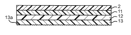
図1において、本第1実施形態にかかる加飾シート1は、基体シート2と、基体シート2上に積層された転写層3とを有している。転写層3は、剥離層11と、柄層12と、アンカー層13と、第1金属光沢膜層14と、第2金属光沢膜層15と、接着層16とを順に積層して構成されている。
In FIG. 1, a
基体シート2は、転写層3を支持するシートである。基体シート2としては、例えば、ポロピレン系樹脂、ポリスチレン系樹脂、ポリアミド系樹脂、ポリエステル系樹脂、アクリル系樹脂、ポリ塩化ビニル系樹脂などの樹脂シート、アルミニウム箔、銅箔などの金属箔、グラシン紙、コート紙、セロハンなどのセルロース系シート、あるいはこれらが複合されたシートなどを用いることができる。
The
剥離層11は、基体シート2を転写層3から剥離させるための層である。剥離層11は、転写後又は成形同時加飾後に基体シート2を転写層3から剥離した際、加飾品の最外面となる層である。このため、剥離層11は、ハードコート機能を有していることが好ましい。剥離層11の材質としては、例えば、アクリル系樹脂、ポリエステル系樹脂、ポリ塩化ビニル系樹脂、セルロース系樹脂、ゴム系樹脂、ポリウレタン系樹脂、ポリ酢酸ビニル系樹脂などのほか、塩化ビニル−酢酸ビニル系共重合体系樹脂、エチレン−酢酸ビニル共重合体系樹脂などのコポリマーを用いることができる。剥離層11に硬度が必要な場合には、紫外線硬化性樹脂などの光硬化性樹脂、電子線硬化性樹脂などの放射線硬化性樹脂、熱硬化性樹脂などを選定して用いてもよい。剥離層11の形成方法としては、例えば、グラビアコート法、ロールコート法、コンマコート法などのコート法、グラビア印刷法、スクリーン印刷法などの印刷法を用いることができる。
The
柄層12は、絵柄等を表現するための層であり、剥離層11上に、通常は印刷層として形成する。柄層12の材質としては、ポリビニル系樹脂、ポリアミド系樹脂、ポリエステル系樹脂、アクリル系樹脂、ポリウレタン系樹脂、ポリビニルアセタール系樹脂、ポリエステルウレタン系樹脂、セルロースエステル系樹脂、アルキド樹脂などの樹脂をバインダーとし、適切な色の顔料又は染料を着色剤として含有する着色インキなどを用いることができる。柄層12の形成方法としては、グラビア印刷法、スクリーン印刷法、オフセット印刷法などの通常の印刷法を用いることができる。なお、柄層12において、多色刷りや階調表現を行うには、オフセット印刷法やグラビア印刷法が適している。また、柄層12が単色の場合には、グラビアコート法、ロールコート法、コンマコート法などのコート法を用いてもよい。
The
アンカー層13は、互いに隣接する層の密着性を向上させるための層である。アンカー層13の第1金属光沢膜層14側の表面13aは、凹凸形状になっている。アンカー層13の材質としては、塩化ビニル−酢酸ビニル共重合樹脂、ウレタン、ポリエステル、エポキシ樹脂、ポリエチレンなどを用いることができる。なお、アンカー層13の材質として、塩化ビニル系樹脂が用いられることがより好ましい。塩化ビニル系樹脂は、他の樹脂と比べて極性が高いため、金属との相性が良い性質がある。アンカー層13の形成方法としては、グラビア印刷法、スクリーン印刷法などの印刷法を用いることができる。
The
第1及び第2金属光沢膜層14,15は、金属光沢を付与するための層である。第1金属光沢膜層14は、アンカー層13の凹凸形状の表面13a上に形成されている。このため、第1光沢膜層14のアンカー層13側の表面(界面)14aも凹凸形状になっている。
The first and second metallic gloss film layers 14 and 15 are layers for imparting metallic gloss. The first metallic
また、第1金属光沢膜層14は、光透過性を有するように金属材料により構成されている。ここで、金属材料は、所定の厚みの層を形成するまでの過程が2つのタイプに大別される。1つは、形成工程の初期においては多数の島状構造物を形成し、形成工程が進行するに従って、それらの島状構造物が互いに隙間無く結合して所定の厚みの層となるタイプである。このようなタイプの金属材料としては、スズ、インジウム、亜鉛などが挙げられる。もう1つは、薄い層を形成し、形成工程が進行するに従ってその層が複数積層されることで所定の厚みの層となるタイプである。このようなタイプの金属材料としては、アルミニウム、クロム、ニッケルなどが挙げられる。第1金属光沢膜層14の材料として、スズ、インジウム、亜鉛などの島状構造を形成する金属材料を用いた場合には、島状構造を有するように第1金属光沢膜層14を形成することで(すなわち、島状構造が互いに結合して層となる前に形成をストップすることで)、第1金属光沢膜層14が光透過性を有するように構成することができる。このように構成された第1金属光沢膜層14は電波透過性も有する。また、第1金属光沢膜層14の材料として、アルミニウムなどのような島状構造を形成しない金属材料を用いた場合には、第1金属光沢膜層13の厚さを薄く(例えば、0.01μm〜0.1μm程度)することにより、第1金属光沢膜層14が光透過性を有するように構成することができる。
Moreover, the 1st metallic
第2金属光沢膜層15は、光反射性を有するように金属材料により構成されている。例えば、第2金属光沢膜層15の材料としてスズを用いた場合には、多数の島状構造物が互いに結合して所定の厚みの層となるまで形成工程を続けることで、第2金属光沢膜層15が光反射性を有するように構成することができる。また、例えば、第2金属光沢膜層15の材料としてアルミニウムを用いた場合には、第2金属光沢膜層15を所定の厚み以上に形成することで、第2金属光沢膜層15が光反射性を有するように構成することができる。
The second metallic
また、第2金属光沢膜15は、第1金属光沢膜14と隣接する表面(第1金属光沢膜14との界面)15aが平坦に形成されている。
Further, the second
第1及び第2金属光沢膜層14,15の形成方法としては、真空蒸着法、スパッターリング法、イオンプレーティング法、鍍金法などの方法を用いることができる。また、第1及び第2金属光沢膜層14,15の形成は、前記方法によってそれぞれ個別に行ってもよいが、同時蒸着法を利用して同時に行うことが好ましい。これにより、加飾シート1の製造工程の工数を少なくすることができる。第1及び第2金属光沢膜層14,15を同時蒸着する装置としては、例えば、神港精機社製AAMF−C2280SPBR(製品名)を用いることができる。
As a method for forming the first and second metallic glossy film layers 14 and 15, methods such as a vacuum deposition method, a sputtering method, an ion plating method, and a plating method can be used. Moreover, although formation of the 1st and 2nd metallic glossy film layers 14 and 15 may be performed separately by the said method, it is preferable to carry out simultaneously using a simultaneous vapor deposition method. Thereby, the man-hour of the manufacturing process of the
なお、アンカー層13の材料として塩化ビニル系樹脂のようなハロゲンを含む樹脂材料を用いた場合や、ヒドロキシル基やアミンを有する樹脂材料を用いた場合には、ハロゲンや上記官能基が光によってラジカル化される。ラジカル化されたハロゲンは、空気中に含まれる水分(湿気)と反応してハロゲン化水素又はオキソ酸を形成し、ラジカル化された官能基は一定時間、ラジカルの状態で存在する。この場合、第1金属光沢膜層14が酸化され、その金属光沢が失われることになる。この問題は、第1金属光沢膜層14を、第2金属光沢膜層15の金属材料よりも酸化還元電位が0.05V以上、より好ましくは0.1V以上高い金属材料で構成することで改善することができる。このように構成することにより、第2金属光沢膜層15から第1金属光沢膜層14へ電子が流れ込むことができるので、第1金属光沢膜層14の酸化を防止することができる。
When a resin material containing halogen such as vinyl chloride resin is used as the material of the
接着層16は、転写層3と被転写物(物品表面)とを接着するための層である。接着層16の材質としては、被転写物の材質に適した感熱性又は感圧性の樹脂を適宜使用することができる。例えば、被転写物の材質がアクリル系樹脂の場合には、アクリル系樹脂を用いるとよい。また、被転写物の材質がポリフェニレンオキシド・ポリスチレン系樹脂、ポリカーボネート系樹脂、スチレン共重合体系樹脂、ポリスチレン系ブレンド樹脂の場合には、これらの樹脂と親和性のあるアクリル系樹脂、ポリスチレン系樹脂、ポリアミド系樹脂などを用いるとよい。また、樹脂成形品の材質がポリプロピレン樹脂の場合には、塩素化ポリオレフィン樹脂、塩素化エチレン−酢酸ビニル共重合体樹脂、環化ゴム、クマロンインデン樹脂を用いるとよい。接着層16の形成方法としては、グラビアコート法、ロールコート法、コンマコート法などのコート法、グラビア印刷法、スクリーン印刷法などの印刷法を用いることができる。
The
本発明の第1実施形態によれば、第1金属光沢膜層14が光透過性を有し、第2金属光沢膜層15が光反射性を有している。これにより、基体シート2側から加飾シート1に入射した光は、図2の点線で示すように第1金属光沢膜層14の凹凸形状の表面14aで反射されることなく、図2の一点破線で示すように第1金属光沢膜層14を透過し第2金属光沢膜層15の表面15aで反射される。第2金属光沢膜層の表面15aは平坦であるので、当該表面15aで反射される光には光路差Lが生じない。従って、基体シート2の表面部分に干渉縞が発生することを抑制することができる。
According to the first embodiment of the present invention, the first metallic
なお、厳密には、第1金属光沢膜層14の光透過率に応じて、加飾シート1に入射した光の一部の成分は、図2の点線で示すように第1金属光沢膜層14の凹凸形状の表面14aで反射される。しかしながら、加飾シート1に入射した光の他の成分は、第1金属光沢膜14を透過し第2金属光沢膜層15の表面15aで反射される。従って、従来よりも基体シート2の表面部分に干渉縞が発生することを抑制することができる。
Strictly speaking, depending on the light transmittance of the first metallic
なお、第1金属光沢膜層14の光透過率は、5%以上70%以下であることが好ましい。第1金属光沢膜層14の光透過率が5%未満であると、第1金属光沢膜層14の電波透過性の機能が損なわれる。一方、第1金属光沢膜層14の光透過率が70%より大きいと、第1金属光沢膜層14がほとんど透明になり、第1金属光沢膜層14の金属光沢が損なわれる。
The light transmittance of the first metallic
なお、本発明は前記第1実施形態に限定されるものではなく、その他種々の態様で実施できる。例えば、前記では、転写層3は、剥離層11と、柄層12と、アンカー層13と、第1及び第2金属光沢膜層14,15と、接着層16とを備えるように構成したが、本発明はこれに限定されない。例えば、転写層3は、さらに離型層を備えていてもよい。
In addition, this invention is not limited to the said 1st Embodiment, It can implement in another various aspect. For example, in the above description, the
離型層は、基体シート2からの剥離層11の剥離性を向上させるための層である。このため、離型層を設ける場合には、基体シート2と剥離層11との間に配置すればよい。離型層の材質としては、メラミン樹脂系離型剤、シリコーン樹脂系離型剤、フッ素樹脂系離型剤、セルロース誘導体系離型剤、尿素樹脂系離型剤、ポリオレフィン樹脂系離型剤、パラフィン系離型剤、及びこれらの複合型離型剤などを用いることができる。離型層の形成方法としては、ロールコート法、スプレーコート法などのコート法、グラビア印刷法、スクリーン印刷法などを用いることができる。
The release layer is a layer for improving the peelability of the
また、前記第1実施形態では、アンカー層13を柄層12と第1金属光沢膜層14との間にのみ設けたが、本発明はこれに限定されない。例えば、アンカー層13は、基体シート2と離型層との間、剥離層11と柄層12との間、又は第2金属光沢膜層15と接着層16との間にも設けられてもよい。
In the first embodiment, the
《第2実施形態》
図3は、本発明の第2実施形態にかかる加飾シートの断面図である。本第2実施形態の加飾シート1Aが前記第1実施形態の加飾シート1と異なる点は、第2金属光沢膜層15Aが第1金属光沢膜層14上に部分的に形成(パターン形成)されている点である。
<< Second Embodiment >>
FIG. 3 is a cross-sectional view of a decorative sheet according to the second embodiment of the present invention. The
第1金属光沢膜層14は光透過性を有しているので、基体シート2側から見たとき、第1金属光沢膜層14と第2金属光沢膜層15Aとが重なる部分の金属光沢は、それ以外の部分の金属光沢と異なる。すなわち、本第2実施形態の加飾シート1Aは、2色の金属光沢を有する。従って、デザインの多様化を図ることができる。なお、本第2実施形態においては、2層の金属光沢膜層を設けたが、3層以上の金属光沢膜層を設けてもよい。これにより、更なるデザインの多様化を図ることが可能になる。
Since the first metallic
第1及び第2金属光沢膜層14,15Aは、例えば、図4A〜図4E及び図5に示す手順により形成することができる。図4A〜図4Eは、第1及び第2金属光沢膜層14,15Aの製造方法を示す断面図である。図5は、第1及び第2金属光沢膜層14,15Aの製造方法を示すフローチャートである。なお、ここでは、図4Aに示すように、基体シート2上に剥離層11、柄層12、及びアンカー層13が既に形成されているものとして説明を始める。
The first and second metallic glossy film layers 14 and 15A can be formed, for example, by the procedure shown in FIGS. 4A to 4E and FIG. 4A to 4E are cross-sectional views showing a method for manufacturing the first and second metallic glossy film layers 14 and 15A. FIG. 5 is a flowchart showing a method of manufacturing the first and second metallic glossy film layers 14 and 15A. Here, as shown in FIG. 4A, the description is started on the assumption that the
まず、図4Bに示すように、アンカー層13上に第1金属光沢膜層14を形成する(ステップS1)。
次いで、図4Cに示すように、第1金属光沢膜層14上に水溶性パターン層17を部分的に形成(パターン形成)する(ステップS2)。
次いで、図4Dに示すように、第1金属光沢膜層14と水溶性パターン層17とを覆うように、第2金属光沢膜層15Bを形成する(ステップS3)。
First, as shown in FIG. 4B, a first metallic
Next, as shown in FIG. 4C, a water-
Next, as shown in FIG. 4D, a second metallic glossy film layer 15B is formed so as to cover the first metallic
次いで、水洗処理を行う(ステップS4)。これにより、図4Eに示すように、水溶性パターン層17とともに、水溶性パターン層17上に形成された第2金属光沢膜層15Aaが除去され、第2金属光沢膜層15Aが第1金属光沢膜層14上に部分的に形成される。
Subsequently, a water washing process is performed (step S4). As a result, as shown in FIG. 4E, the second metal glossy film layer 15Aa formed on the water-
ステップS4の後、第1及び第2金属光沢膜層14,15Aを覆うように接着層16を形成することで、図3に示す加飾シート1Aを製造することができる。
After step S4, the
なお、金属光沢膜層の金属材料としては、アルミニウムが強靱で均一性に優れた性質を有することから、アルミニウムを用いることが好ましい。しかしながら、アルミニウムは、水によって腐食(酸化)しやすい性質も有する。このため、第1又は第2金属光沢膜層14,15Aの金属材料としてアルミニウムを用いる場合には、前記水洗処理を必要としない前記方法とは別の製造方法が求められる。また、前記製造方法では、第2金属光沢膜層15Aを形成する前に第1金属光沢膜層14上に水溶性パターン17を形成する必要があるので、前述した同時蒸着法を利用して加飾シート1Aの製造工程の工数を少なくすることができない。
As the metallic material for the metallic gloss film layer, aluminum is preferably used because aluminum has toughness and excellent uniformity. However, aluminum also has the property of being easily corroded (oxidized) by water. For this reason, when using aluminum as a metal material of the 1st or 2nd metallic
次に、前記課題を解決する加飾シート1Aの製造方法について、図6A〜図6E及び図6を用いて説明する。図6A〜図6Fは、第1及び第2金属光沢膜層14,15Aの前記方法とは別の製造方法を示す断面図である。図7は、第1及び第2金属光沢膜層14,15Aの前記方法とは別の製造方法を示すフローチャートである。なお、ここでは、図6Aに示すように、基体シート2上に剥離層11、柄層12、及びアンカー層13が既に形成されているものとして説明を始める。
Next, a method for manufacturing the
まず、図6Bに示すように、アンカー層13上に第1及び第2金属光沢膜層14,15Abを同時蒸着により形成する(ステップS11)。なお、第1及び第2金属光沢膜層14,15Abの金属材料は、互いに異なる金属材料とする。
First, as shown in FIG. 6B, first and second metallic glossy film layers 14 and 15Ab are formed on the
次いで、図6Cに示すように、第2金属光沢膜層15Ab上に部分的にレジスト層18を形成する(ステップS12)。なお、レジスト層18の材質としては、エポキシ樹脂やアクリル樹脂、塩化ビニル-酢酸ビニル共重合樹脂、紫外線硬化型樹脂などを用いることができる。レジスト層18の形成方法としては、例えば、ロールコート法、スプレーコート法などのコート法、グラビア印刷法、スクリーン印刷法、フレキソ印刷法などを用いることができる。
Next, as shown in FIG. 6C, a resist
次いで、第2金属光沢膜層15Abのみを溶解させるエッチング液を用いて、第2金属光沢膜層15Abをエッチングする(ステップS13)。これにより、図6Dに示すように、第1金属光沢膜層14上に部分的に第2金属光沢膜層15Aが形成される。
Next, the second metal gloss film layer 15Ab is etched using an etchant that dissolves only the second metal gloss film layer 15Ab (step S13). As a result, as shown in FIG. 6D, the second metallic
ステップS13の後、レジスト層18を除去し、第1及び第2金属光沢膜層14,15Aを覆うように接着層16を形成することで、図3に示す加飾シート1Aを製造することができる。なお、レジスト層18は、他の層に悪影響を及ぼさない場合には、除去する必要はない。すなわち、図8に示す加飾シート1Bのように、第2金属光沢膜層15Aにレジスト層18が付着したまま接着層16を形成するようにしてもよい。これにより、レジスト層18を除去する工程を無くして、加飾シート1Bの製造工程の工数を少なくすることができる。
After step S13, the
なお、第2金属光沢膜層15Abのみを溶解させるには、例えば、第1金属光沢膜層14の材料としてアルミニウムを用い、第2金属光沢膜層15Abの材料としてスズを用い、エッチング液の材料として濃硝酸を用いればよい。濃硝酸は、アルミニウムは溶解させることができないが、スズは溶解させることができる。従って、前記のように第1及び第2金属光沢膜層14,15Ab及びエッチング液の材料を選択することで、第2金属光沢膜層15Abのみを溶解させることができる。
In order to dissolve only the second metal gloss film layer 15Ab, for example, aluminum is used as the material of the first metal
また、第1金属光沢膜層14の材料としてクロム、ニッケルなどの酸性溶液のみに溶解する金属材料を用い、第2金属光沢膜層15Abの材料としてアルミニウム、スズ、亜鉛、鉛などの両性金属を用い、エッチング液の材料としてアルカリ性溶液を用いてもよい。この場合、アルカリ性溶液により、両性金属である第2金属光沢膜層15Abのみを溶解させることができる。また、第1金属光沢膜層14の材料としてアルカリ性溶液のみに溶解する金属材料を用い、第2金属光沢膜層15Abの材料として両性金属を用い、エッチング液の材料として酸性溶液を用いてもよい。この場合、酸性溶液により、両性金属である第2金属光沢膜層15Abのみを溶解させることができる。
In addition, a metal material that dissolves only in an acidic solution such as chromium or nickel is used as the material of the first metallic
また、第1金属光沢膜層14の材料として金、銀、銅などの酸化還元電位の大きい金属材料を用い、第2金属光沢膜層15Abの材料としてアルミニウムなどの酸化還元電位の低い金属材料を用い、エッチング液の材料として酸化力の弱い希塩酸、希硫酸などの希酸を用いてもよい。酸化還元電位の大きい金、銀、銅などの金属は、希酸には溶解しないため、第2金属光沢膜15Abの材料に希酸で溶解する金属材料を用いることで、第2金属光沢膜層15Abのみを溶解させることができる。
Further, a metal material having a high redox potential such as gold, silver, or copper is used as the material of the first metallic
なお、第2金属光沢膜層15Abのみを溶解させるための材料の組合せ例について上述したが、本発明はこれらの組合せ例に限定されるものではない。 In addition, although the combination example of the material for dissolving only 2nd metal glossy film layer 15Ab was mentioned above, this invention is not limited to these combination examples.
図6A〜図6Dに示す製造方法によれば、第1及び第2金属光沢膜層14,15Abを同時形成した後、第2金属光沢膜層15Abのみを選択的にエッチングするようにしているので、少ない工数で2色の金属光沢を有する加飾シート1Bを製造することができる。また、水洗工程を行う必要がないので、第1又は第2金属光沢膜層14,15Aの材料として、アルミニウムのような、水によって腐食(酸化)しやすい性質を持つ金属材料を用いることができる。 According to the manufacturing method shown in FIGS. 6A to 6D, after the first and second metallic glossy film layers 14 and 15Ab are simultaneously formed, only the second metallic glossy film layer 15Ab is selectively etched. The decorative sheet 1B having two-color metallic luster can be manufactured with a small number of man-hours. In addition, since it is not necessary to perform a water washing step, a metal material having the property of being easily corroded (oxidized) by water, such as aluminum, can be used as the material of the first or second metallic glossy film layers 14 and 15A. .
なお、互いに隣接する2層の金属光沢膜層のうちの1層のみをエッチングする方法としては、エッチングの時間を調整する方法が考えられる。しかしながら、本発明において、第1金属光沢膜層14は光透過性を有するように構成されているので、その厚さが、例えば0.01μm〜0.1μm程度と非常に薄くなる。このため、エッチングの時間を調整して第2金属光沢膜層15Abのみをエッチングすることは相当困難である。
As a method for etching only one of the two metallic gloss film layers adjacent to each other, a method of adjusting the etching time is conceivable. However, in the present invention, since the first metallic
これに対して、図6A〜図6Dに示す製造方法によれば、第1及び第2金属光沢膜層14,15Abの材料を互いに異ならせ、第2金属光沢膜層15Abのみを選択的にエッチングするようにしているので、第1及び第2金属光沢膜層14,15Abの厚さに関わらず、第2金属光沢膜層15Abのみを容易にエッチングすることができる。 On the other hand, according to the manufacturing method shown in FIGS. 6A to 6D, the materials of the first and second metallic glossy film layers 14 and 15Ab are made different from each other, and only the second metallic glossy film layer 15Ab is selectively etched. Thus, only the second metal gloss film layer 15Ab can be easily etched regardless of the thicknesses of the first and second metal gloss film layers 14 and 15Ab.
なお、本第2実施形態にかかる加飾シート1Aにより、携帯電話などのアンテナを備える電子機器の筐体を加飾する場合、第1金属光沢膜層をスズやインジウムなどの金属材料により島状構造を有するように構成するともに、アンテナを図9に示すように配置することが好ましい。すなわち、アンテナ21は、筐体22の表面に貼着された加飾シート1Aにおける第1金属光沢膜層14の第2金属光沢膜層15Aが設けられていない領域14bと対向するように設けることが好ましい。前述したように、スズやインジウムなどの金属材料により島状構造を有するように構成された第1金属光沢膜層14は電波透過性を有する。従って、アンテナ21を図9に示すように配置することにより、アンテナ21に電波を送受信させることができる。
In addition, when decorating the housing | casing of electronic devices provided with antennas, such as a mobile telephone, with the decorating sheet |
本発明にかかる加飾シート及びその製造方法は、基体シートの表面部分に干渉縞が発生することを抑制することができるので、携帯電話やパーソナルコンピュータの筐体に用いられる樹脂成形品などの物品表面を加飾するのに有用である。 Since the decorative sheet and the manufacturing method thereof according to the present invention can suppress the occurrence of interference fringes on the surface portion of the base sheet, articles such as resin molded products used in the casings of mobile phones and personal computers Useful for decorating the surface.
1,1A,1B 加飾シート
2 基体シート
3 転写層
11 剥離層
12 柄層
13 アンカー層
14 第1金属光沢膜層
15,15A 第2金属光沢膜層
16 接着層
17 水溶性パターン層
18 レジスト層
1, 1A, 1B
Claims (15)
前記第1金属光沢膜層は、光透過性を有し、前記基体シート側の表面が凹凸形状に形成され、
前記第2金属光沢膜層は、光反射性を有し、前記第1金属光沢膜層の前記基体シート側とは反対側の表面に隣接して設けられ、前記第1金属光沢膜層との界面が平坦である、加飾シート。 A decorative sheet in which a transfer layer including at least a first metallic glossy film layer and a second metallic glossy film layer is formed on a base sheet,
The first metallic glossy film layer has light transmittance, and the surface on the base sheet side is formed in an uneven shape,
The second metallic glossy film layer has light reflectivity and is provided adjacent to a surface of the first metal glossy film layer opposite to the base sheet side, A decorative sheet with a flat interface.
前記第1金属光沢膜層は、島状構造を有するように構成され、
前記第1金属光沢膜層の前記第2金属光沢膜層が設けられていない領域と対向するようにアンテナが設けられている、加飾品。 A decorative item decorated with the decorative sheet according to claim 6 or 7,
The first metallic gloss film layer is configured to have an island structure,
A decorative product in which an antenna is provided so as to face a region of the first metal glossy film layer where the second metal glossy film layer is not provided.
光透過性を有し且つ前記基体シート側の表面に凹凸形状が形成されるように前記第1金属光沢膜層を形成するとともに、
前記第1金属光沢膜層の前記基体シートとは反対側の表面上に、光反射性を有し且つ前記第1金属光沢膜層との界面が平坦になるように前記第2金属光沢膜層を積層形成する、
ことを含む、加飾シートの製造方法。 A method for producing a decorative sheet in which a transfer layer including at least a first metallic glossy film layer and a second metallic glossy film layer is formed on a base sheet,
While forming the first metallic gloss film layer so as to have a light transmittance and an uneven shape is formed on the surface of the base sheet side,
On the surface of the first metallic glossy film layer opposite to the base sheet, the second metallic glossy film layer has light reflectivity and has a flat interface with the first metallic glossy film layer. Layered,
The manufacturing method of a decorating sheet including this.
前記第2金属光沢膜層のみを溶解させるエッチング液を用いて、前記第2金属光沢膜層をエッチングする、
ことを含む、請求項11に記載の加飾シートの製造方法。 After the second metallic glossy film layer is laminated, a resist layer is partially formed on the second metallic glossy film layer,
Etching the second metallic glossy film layer using an etchant that dissolves only the second metallic glossy film layer;
The manufacturing method of the decorating sheet of Claim 11 containing this.
Priority Applications (1)
| Application Number | Priority Date | Filing Date | Title |
|---|---|---|---|
| JP2009205974A JP2011056683A (en) | 2009-09-07 | 2009-09-07 | Decorative sheet, method for manufacturing the same, and decorative article |
Applications Claiming Priority (1)
| Application Number | Priority Date | Filing Date | Title |
|---|---|---|---|
| JP2009205974A JP2011056683A (en) | 2009-09-07 | 2009-09-07 | Decorative sheet, method for manufacturing the same, and decorative article |
Publications (1)
| Publication Number | Publication Date |
|---|---|
| JP2011056683A true JP2011056683A (en) | 2011-03-24 |
Family
ID=43944922
Family Applications (1)
| Application Number | Title | Priority Date | Filing Date |
|---|---|---|---|
| JP2009205974A Withdrawn JP2011056683A (en) | 2009-09-07 | 2009-09-07 | Decorative sheet, method for manufacturing the same, and decorative article |
Country Status (1)
| Country | Link |
|---|---|
| JP (1) | JP2011056683A (en) |
Cited By (7)
| Publication number | Priority date | Publication date | Assignee | Title |
|---|---|---|---|---|
| WO2013141551A1 (en) * | 2012-03-19 | 2013-09-26 | Lg Hausys, Ltd. | In-mold transfer film and method for fabricating the same |
| CN103374724A (en) * | 2012-04-12 | 2013-10-30 | 钜永真空科技股份有限公司 | Colored film and manufacturing method thereof |
| CN107009571A (en) * | 2017-03-29 | 2017-08-04 | 维沃移动通信有限公司 | A kind of plastic surface processing method, plastic surface and combined shell |
| WO2021095789A1 (en) * | 2019-11-14 | 2021-05-20 | Nissha株式会社 | Cover with antenna function |
| WO2021200165A1 (en) * | 2020-03-31 | 2021-10-07 | 大日本印刷株式会社 | Transfer sheet, decorative material, and method for producing decorative material |
| US11524482B2 (en) | 2017-12-15 | 2022-12-13 | Lg Chem, Ltd. | Decoration member and method for producing same |
| US12053073B2 (en) | 2018-04-10 | 2024-08-06 | Lg Chem, Ltd. | Decoration member and method for manufacturing same |
-
2009
- 2009-09-07 JP JP2009205974A patent/JP2011056683A/en not_active Withdrawn
Cited By (12)
| Publication number | Priority date | Publication date | Assignee | Title |
|---|---|---|---|---|
| WO2013141551A1 (en) * | 2012-03-19 | 2013-09-26 | Lg Hausys, Ltd. | In-mold transfer film and method for fabricating the same |
| CN103374724A (en) * | 2012-04-12 | 2013-10-30 | 钜永真空科技股份有限公司 | Colored film and manufacturing method thereof |
| CN107009571A (en) * | 2017-03-29 | 2017-08-04 | 维沃移动通信有限公司 | A kind of plastic surface processing method, plastic surface and combined shell |
| US11524482B2 (en) | 2017-12-15 | 2022-12-13 | Lg Chem, Ltd. | Decoration member and method for producing same |
| US12053073B2 (en) | 2018-04-10 | 2024-08-06 | Lg Chem, Ltd. | Decoration member and method for manufacturing same |
| WO2021095789A1 (en) * | 2019-11-14 | 2021-05-20 | Nissha株式会社 | Cover with antenna function |
| JPWO2021095789A1 (en) * | 2019-11-14 | 2021-11-25 | Nissha株式会社 | Cover with antenna function |
| JP7018546B2 (en) | 2019-11-14 | 2022-02-10 | Nissha株式会社 | Cover with antenna function |
| CN114728506A (en) * | 2019-11-14 | 2022-07-08 | Nissha株式会社 | Cover with antenna function |
| CN114728506B (en) * | 2019-11-14 | 2024-01-05 | Nissha株式会社 | Cover with antenna function |
| US12074388B2 (en) | 2019-11-14 | 2024-08-27 | Nissha Co., Ltd. | Cover with antenna function |
| WO2021200165A1 (en) * | 2020-03-31 | 2021-10-07 | 大日本印刷株式会社 | Transfer sheet, decorative material, and method for producing decorative material |
Similar Documents
| Publication | Publication Date | Title |
|---|---|---|
| JP2011056683A (en) | Decorative sheet, method for manufacturing the same, and decorative article | |
| JP5068829B2 (en) | Simultaneous injection-molded decorative product with antenna, method for manufacturing the same, and feeding structure of housing with antenna | |
| JP2011167844A (en) | Transfer sheet containing interference fringe inhibitor and decorative molded article of the same | |
| JP4601262B2 (en) | Cover panel with metallic color | |
| JP4963634B2 (en) | Decorative sheet, method for producing decorative sheet, and method for producing decorative molded product | |
| EP2808167B1 (en) | Method of manufacturing case frame | |
| WO2020153137A1 (en) | Structure, decorative film, method for manufacturing structure, and method for manufacturing decorative film | |
| JP4963635B2 (en) | Decorative sheet, method for producing decorative sheet, and method for producing decorative molded product | |
| JP2002040208A (en) | Antireflection cover component and method for producing the same | |
| CN201566222U (en) | Transfer printing film with three-dimensional matte patterns | |
| JP3643904B1 (en) | Method for producing metal-deposited film and metal-deposited film | |
| JP5896401B2 (en) | Decorative sheet for metal molded resin composite casing and metal molded resin composite decorative casing | |
| JP2011126236A (en) | Resin casing with functional component and method for manufacturing the same | |
| JP2006281591A (en) | Decorative sheet with metallic gloss and decorative molding using the sheet | |
| JP3736840B2 (en) | Anti-reflection transfer material | |
| JP4964073B2 (en) | Decorative sheet and its manufacturing method, decorative molded product | |
| JP2006255894A (en) | Hairline like decorative sheet | |
| JP2001310351A (en) | Method for manufacturing reflection preventing molded article | |
| JP2014144568A (en) | Smooth decorative sheet and production method of the same | |
| JP3686720B2 (en) | Key button manufacturing method and key button | |
| CN114885552B (en) | Electronic device, housing and preparation method thereof | |
| JP2009029055A (en) | Manufacturing method of decorative sheet and manufacturing method of decorative molded article | |
| JP2005349778A (en) | Decorating method and decorating member | |
| TWM336156U (en) | Decorating film with metallic feel | |
| JP5038351B2 (en) | Decorative sheet and manufacturing method thereof |
Legal Events
| Date | Code | Title | Description |
|---|---|---|---|
| A300 | Application deemed to be withdrawn because no request for examination was validly filed |
Free format text: JAPANESE INTERMEDIATE CODE: A300 Effective date: 20121204 |