JP2011055494A - Echo canceller - Google Patents
Echo canceller Download PDFInfo
- Publication number
- JP2011055494A JP2011055494A JP2010192208A JP2010192208A JP2011055494A JP 2011055494 A JP2011055494 A JP 2011055494A JP 2010192208 A JP2010192208 A JP 2010192208A JP 2010192208 A JP2010192208 A JP 2010192208A JP 2011055494 A JP2011055494 A JP 2011055494A
- Authority
- JP
- Japan
- Prior art keywords
- signal
- tone
- echo
- adaptive filter
- input
- Prior art date
- Legal status (The legal status is an assumption and is not a legal conclusion. Google has not performed a legal analysis and makes no representation as to the accuracy of the status listed.)
- Pending
Links
Images


Landscapes
- Cable Transmission Systems, Equalization Of Radio And Reduction Of Echo (AREA)
- Telephone Function (AREA)
Abstract
Description
本発明はエコーキャンセラに関し、例えば、電話端末を収容したVoIP端末に設けられるエコーキャンセラに適用し得るものである。 The present invention relates to an echo canceller and can be applied to, for example, an echo canceller provided in a VoIP terminal accommodating a telephone terminal.
ハイブリッド回路におけるエコー成分を除去するエコーキャンセラは、一般には、受信信号がハイブリッド回路を介して送信信号の経路に流れ、エコー成分になって音声品質を低下させることを防止するために設けられている。ところで、エコー成分となり得る受信信号は、音声信号が一般的であるが、トーン信号が受信信号になることもある。 An echo canceller that removes an echo component in a hybrid circuit is generally provided to prevent a received signal from flowing through a path of a transmission signal through the hybrid circuit and becoming an echo component to reduce voice quality. . By the way, a reception signal that can be an echo component is generally an audio signal, but a tone signal may be a reception signal.
従来、トーン信号が受信信号になった場合を考慮したエコーキャンセラとして、特許文献1に記載されているものがある。特許文献1に記載されているエコーキャンセラの構成などについては、課題の説明の項で明らかにする。
Conventionally, there is an echo canceller described in
特許文献1に記載のエコーキャンセラは、以下のような課題1〜課題4を有するものであった。特許文献1に記載のエコーキャンセラを、以下では、従来技術と呼ぶ。
The echo canceller described in
(課題1)
トーン信号によって適応フィルタの係数が破壊され後でしか、エコーキャンセラ(又は適応フィルタ)にトーン信号が入力されたことが分からないので、多くの場合、何らかの対策を施しても手遅れであり、また、再収束しようにも、係数値が収束の初期状態としては不適であるので、再び性能が発揮できるまで時間がかかってしまう。
(Problem 1)
Since it is not known that the tone signal is input to the echo canceller (or the adaptive filter) only after the coefficient of the adaptive filter is destroyed by the tone signal, in many cases, it is too late even if some measures are taken, Even if re-convergence is attempted, the coefficient value is inappropriate as the initial state of convergence, so it takes time until the performance can be exhibited again.
従来技術は、基本的に適応フィルタがトーン成分に収束してからトーン信号であることが検出できる仕組みになっている。すなわち、適応フィルタにトーン信号が入力される前には、音声などによって、せっかく広い帯域の好適な周波数特性を持った係数を推定できていたとしても、一旦、フィルタ係数がトーン性を持つように破壊された後で、係数がトーンの周波数特性に一致するかどうかを判定するため、判定後に続くいろいろな処理、例えば、適応フィルタの係数更新の可否などに使うには手遅れであることが多い。また、エコーキャンセラが仮に初期状態であったり、一旦収束状態で再収束を実行する場合であったりしても、トーン信号によって誤収束した適応フィルタの係数は再収束のための初期値としては適切でないので、再収束に時間がかかり、その間、エコー成分が消えないので通話品質が劣化してしまう。 The prior art basically has a mechanism that can detect that the signal is a tone signal after the adaptive filter converges on the tone component. That is, even before a tone signal is input to the adaptive filter, even if a coefficient having a suitable frequency characteristic in a wide band can be estimated by voice or the like, the filter coefficient once has tone characteristics. In order to determine whether or not the coefficient matches the frequency characteristic of the tone after being destroyed, it is often too late to use for various processes following the determination, for example, whether or not the coefficient of the adaptive filter can be updated. Even if the echo canceller is in the initial state, or when reconvergence is executed once in the converged state, the coefficient of the adaptive filter erroneously converged by the tone signal is appropriate as the initial value for reconvergence. Therefore, reconvergence takes time, and during that time, the echo component does not disappear, so the call quality deteriorates.
(課題2)
初期遅延が小さいとき、所望の動作をしない。
(Problem 2)
When the initial delay is small, the desired operation is not performed.
従来技術によれば、エコーキャンセラがトーン性の信号を参照信号としてエコー経路を推定したとき、エコーキャンセラの適応フィルタ係数レジスタは当該入力トーン周波数に収束する。しかし、エコー経路の初期遅延が小さいとき、従来技術は効果を発揮しない場合が多い。なぜならば、エコー経路の初期遅延が小さいときは、実際には係数レジスタは当該入力トーン周波数に収束しない場合が多いからである。 According to the prior art, when the echo canceller estimates an echo path using a tone signal as a reference signal, the adaptive filter coefficient register of the echo canceller converges to the input tone frequency. However, when the initial delay of the echo path is small, the conventional technique often does not exert an effect. This is because, when the initial delay of the echo path is small, the coefficient register actually does not converge to the input tone frequency in many cases.
以下、従来技術の課題2を、図2及び図3を参照しながら説明する。最初に、従来技術が適用できるケースを示し、その後に、従来技術が適用できないケースの実例を示すことにする。
Hereinafter,
図2(a)は初期遅延50サンプルのエコー経路を示し、このエコー経路は、図2(c)に示すように、周波数特性が0〜8kHzまでほぼ平坦なエコー経路である。エコーキャンセラにトーン(この説明例ではダイヤルトーン400Hzにしている)を入力し、係数レジスタを収束させた結果を図2(b)に示している。図2(c)には、エコー経路の周波数特性と収束後の係数レジスタの周波数特性の両方を示している。図2(b)から分かるように、エコーキャンセラの適応フィルタ係数は、波形的にも入力トーンに良く似た状態に収束しており、周波数特性を示した図2(c)からもエコー経路のうち、トーン周波数部分だけが大きな成分を持っていることが分かる。 FIG. 2A shows an echo path with an initial delay of 50 samples. As shown in FIG. 2C, this echo path is an echo path having a substantially flat frequency characteristic from 0 to 8 kHz. FIG. 2B shows a result obtained by inputting a tone (a dial tone of 400 Hz in this example) to the echo canceller and converging the coefficient register. FIG. 2C shows both the frequency characteristic of the echo path and the frequency characteristic of the coefficient register after convergence. As can be seen from FIG. 2B, the adaptive filter coefficients of the echo canceller have converged to a state that is very similar to the input tone in terms of waveform, and from FIG. It can be seen that only the tone frequency portion has a large component.
一方、初期遅延が10サンプルのエコー経路でエコーキャンセラを動作した場合の様子を図3(a)〜図3(c)に示している。図3(a)は初期遅延10サンプルのエコー経路を示し、周波数特性は、図3(c)に示すように、0〜8kHzまでほぼ平坦なエコー経路である。上述と同様に、エコーキャンセラにトーン(ダイヤルトーン400Hz)を入力し、係数レジスタを収束させた結果を図3(b)に示している。図3(b)においては、エコーキャンセラの適応フィルタ係数は入力トーンとは異なっており、周波数特性である図3(c)からも入力トーンの400Hzではピ−クを持っていないのが分かる。より詳細に言えば、図3(c)において、は周波数特性の最大は0Hzである。 On the other hand, FIGS. 3A to 3C show a state in which the echo canceller is operated in an echo path having an initial delay of 10 samples. FIG. 3A shows an echo path with an initial delay of 10 samples, and the frequency characteristic is an echo path that is substantially flat from 0 to 8 kHz as shown in FIG. Similarly to the above, FIG. 3B shows the result of convergence of the coefficient register by inputting a tone (400 Hz dial tone) to the echo canceller. In FIG. 3B, the adaptive filter coefficient of the echo canceller is different from that of the input tone, and it can be seen from FIG. 3C that is the frequency characteristic that there is no peak at the input tone of 400 Hz. More specifically, in FIG. 3C, the maximum frequency characteristic is 0 Hz.
しかしながら、図2及び図3に示した両ケースとも、トーン入力に対するエコーの除去に関しては十分な性能を発揮する。説明の例では、双方ともERLE(受信信号と残差のパワー比)が35dB程度を示している。言い換えれば、エコー経路の特性を十分に推定しないにも拘わらず、入力周波数に限定しては、エコー除去性能を発揮しているという状態が起こっている。このような現象は、エコー経路の初期遅延が、トーン周期より小さい場合に頻発する。具体的には、エコーキャンセラと、エコー発生源であるハイブリッド回路の配置が近いとき、例えば、同一装置内にある場合などに必ず発生する。都合の悪いことに、VoIP端末装置などでは、ハイブリッド回路とエコーキャンセラは同一装置内に配置されることの方が通常である。従って、このような場合、係数レジスタの周波数特性は入力トーンを持たないから、係数のトーン性も検出できないことになり、従来技術は効果を発揮しない。 However, both cases shown in FIG. 2 and FIG. 3 exhibit sufficient performance with respect to echo cancellation for tone input. In the example of description, both have ERLE (power ratio of a received signal and a residual) of about 35 dB. In other words, despite the fact that the characteristics of the echo path are not sufficiently estimated, there is a state where the echo canceling performance is exhibited only for the input frequency. Such a phenomenon occurs frequently when the initial delay of the echo path is smaller than the tone period. Specifically, it always occurs when the echo canceller and the hybrid circuit as an echo generation source are close to each other, for example, in the same apparatus. Unfortunately, in a VoIP terminal device or the like, it is normal that the hybrid circuit and the echo canceller are arranged in the same device. Therefore, in such a case, the frequency characteristic of the coefficient register does not have an input tone, so the tone characteristic of the coefficient cannot be detected, and the conventional technique does not exhibit an effect.
(課題3)
エコーキャンセラにトーンが入力された直後のダブルトークでエコー除去性能が激しく劣化する。
(Problem 3)
Echo removal performance is severely degraded by double talk immediately after a tone is input to the echo canceller.
ここで、ダブルトークについて説明しておくと、発呼話者、着呼話者の両者が音声を発生している状態をダブルトークといい、エコーキャンセラでは、送信信号と受信信号が同時に入力されている状態になっている。従来技術でも述べられているように、エコーキャンセラにおいては、ダブルトークのときには、適応フィルタの係数更新を停止する制御を行うため、ERLEを監視してダブルトークの検出を実施することが多い。従来技術では、上述した課題1で示したように、一旦トーン性信号に誤収束した適応フィルタを用いた結果で残差を使ってダブルトーク判定をする。誤収束のフィルタ残差を使うので、正しいダブルトークの判定ができないばかりか、従来技術では、トーン収束後の一定期間は係数更新の速さを制御するステップゲインを大きく設定してしまう。その結果、トーン収束後の一定期間は係数更新の追従性が最も俊敏な状態で、適応フィルタ係数を適応してしまう。このような結果、不適なキャンセルを受けるので非常に音質が劣化する。また、ダブルトークにならないときも、適応フィルタの再収束は、トーン信号への誤収束状態を初期状態として開始されたのと同じであり、たとえ、係数更新を実行しても、安定にエコーを除去できるようになるためには長い時間がかかる。当然に、話者は再収束までの長い時間エコーを聞くことになり通話品質が劣化してしまう。
Here, double talk will be explained. A state where both the calling speaker and the called speaker are producing sound is called double talk. In the echo canceller, a transmission signal and a reception signal are input simultaneously. It is in a state. As described in the prior art, in echo cancellers, in the case of double talk, control for stopping coefficient update of the adaptive filter is performed, so that ERLE is often monitored to detect double talk. In the prior art, as shown in the above-described
(課題4)
従来技術をそのまま用いた場合、内線転送など電話の転送の際、エコーの除去性が劣化する。以下、図4を参照しながら、従来技術の課題4である内線転送時の課題について説明する。
(Problem 4)
When the prior art is used as it is, the echo removability deteriorates at the time of telephone transfer such as extension transmission. Hereinafter, the problem at the time of extension transfer, which is the
図4において、電話機100から電話機109に発呼して、しばらく通話した後、内線転送して電話機110に転送する場合について説明する。従来技術の通り、エコーキャンセラ104は、加算器119の出力と受信入力端子103の入力を用いて、ハイブリッド回路108をエコー経路としてエコー経路の推定を行い、適応フィルタ118の係数をハイブリッド回路108のインパルス応答に等しくなるように推定する。このような推定の結果、電話機100からの話者信号は、ハイブリッド回路101を通り、アナログ/デジタル変換器(A/D変換器)102でデジタル変換されてデジタル信号になった後、デジタル/アナログ変換器(D/A変換器)105でアナログ信号に変換されてスイッチ106を通り、ハイブリッド回路108で2線変換された後、電話機109に至る。電話機109への話者信号の一部は、ハイブリッド回路108で反射され、エコー信号y1となり、スイッチ112を経由してA/D変換器113でデジタル信号に変換された後、加算器119に入力される。加算器119には適応フィルタ(ADF)118から出力された擬似エコー信号y’が入力されており、適応フィルタ118が収束していれば、y’≒y1であるのでエコー(エコー信号y’)が打ち消される。
Referring to FIG. 4, a case will be described in which a call is made from the
適応フィルタ118の係数更新には、公知のNLMS等のアルゴリズムが用いられる。ここで、NLMSアルゴリズムの係数更新の様子を簡単に解説する。 A known algorithm such as NLMS is used to update the coefficient of the adaptive filter 118. Here, how the coefficient of the NLMS algorithm is updated will be briefly explained.
遠端電話機100から受信入力端子に入力される音声信号をx(n)、適応フィルタ118のフィルタ係数をhk(n)とすると、フィルタ係数hk(n)を(1)式及び(2)式に従うように更新する。

なお、(1)式の右辺第2項の分母が0のときには係数更新量=0とするか、又は係数更新を停止する。フィルタ係数をhk(n)は、第nサンプル時刻の第k番目の適応フィルタのタップ係数を表している。また、αはステップゲインであり、適応フィルタ118の収束速度を決める定数であり、0<α<2である。αが大きければ、収束速度が速いが定常特性のぶれ幅が大きく、また、ノイズの影響も大きい。一方、αが小さければ、収束速度は遅いが定常特性のぶれ幅が小さく、また、ノイズの影響も小さい。従来技術によれば、十分に適応フィルタ118が収束した後はステップゲインを小さい値にすることが示されている。
When the denominator of the second term on the right side of equation (1) is 0, the coefficient update amount is set to 0, or the coefficient update is stopped. The filter coefficient h k (n) represents the tap coefficient of the kth adaptive filter at the nth sample time. Α is a step gain, a constant that determines the convergence speed of the
さて、内線転送の際は、一旦、電話機100及び109間で通話がされており、適応フィルタ118の係数もある程度までハイブリッド回路108を推定して収束している。ここで、適応フィルタ118が完全に収束していれば、(2)式のエコー除去残差e(n)=0となるため、係数更新は停止したと同様である。
Now, at the time of extension transfer, a telephone call is once made between the
その後、構内交換機などによって、電話機109から電話機110に通話が転送される場合を、以下、4つのケースについて説明する。ここで、転送が発生すると、スイッチ106の端子はa2に閉じられ、スイッチ112の端子はb2に閉じられる。D/A変換器105から出力された信号は、スイッチ106の端子a2を通り、ハイブリッド回路111を経由して一部は電話機110に出力され、一部はハイブリッド回路111で反射されてエコー信号y2となってスイッチ112の端子b2を経由してA/D変換器113に入力されてSin端子114に入力される。以後、エコーキャンセラの収束状態の良否と転送によるエコー経路変化の大小の組み合わせについて各々説明する。
Thereafter, the case where a call is transferred from the
(課題4;内線転送ケースA)
内線転送ケースAは、適応フィルタ118の収束が不十分であり、ハイブリッド回路108、111の特性がほとんど変わらないときである。
(Problem 4: Extension transfer case A)
The extension transfer case A is when the convergence of the adaptive filter 118 is insufficient and the characteristics of the hybrid circuits 108 and 111 hardly change.
このケースAの転送前の状態の場合、(2)式のエコー除去残差e(n)は0でないので、(1)式の係数更新は有効のまま実行される。つまり、従来技術の通り、x(n)がトーン性の信号であれば、適応フィルタ118の係数は、(1)式に従って、入力x(n)に応じて更新される。その結果、適応フィルタ118の係数は、ハイブリッド回路108の特性というよりもむしろ、トーン性のエコー信号y1を消去するように係数が収束していく。当然、適応フィルタ118の係数は図2で示したように、ハイブリッド回路108のインパルス応答とは異なる特性に収束することになる。その後、転送が発生し、ハイブリッド回路111が接続され、電話機110に接続されて通話が始まる。
In this case A before transfer, the echo cancellation residual e (n) in the equation (2) is not 0, so that the coefficient update in the equation (1) is executed while being valid. That is, as in the prior art, if x (n) is a tone signal, the coefficient of the adaptive filter 118 is updated according to the input x (n) according to the equation (1). As a result, the coefficient of the adaptive filter 118 converges so as to cancel the tone echo signal y1 rather than the characteristic of the hybrid circuit 108. Naturally, the coefficient of the adaptive filter 118 converges to a characteristic different from the impulse response of the hybrid circuit 108 as shown in FIG. Thereafter, transfer occurs, the hybrid circuit 111 is connected, and the
本ケースの場合、ハイブリッド回路特性は転送前後で等しいと考えることができるのだが、適応フィルタ118の係数は、トーンに応じて収束している。その後、非トーン性の信号である音声信号x(n)が入力されると、適応フィルタ118ではトーン信号の成分しか推定していないので、課題2の項目で説明したように、適応フィルタ118の収束状態はハイブリッド回路の応答特性を反映していない。従って、トーン周波数よりも広い周波数成分を持つ音声信号のエコーはほとんど全ての成分で打消し不可能となり、加算器119から出力される。加算器119の出力は、図4に示したようにダブルトーク検出器(DTD)117に入力されている。ダブルトーク検出器117では、加算器出力と受信入力端子からの入力rin(n)との比ERLEの大小を計算し、ERLEの値の大小若しくはERLEの変化の大小でダブルトークを検出する。ERLEは、例えば、(3)式に示すように計算される。
従来技術に述べられているように、ERLEが30dBなどのように値が大きければ、e(n)が十分小さいとして収束状態若しくは収束可能とし、ERLEが6dBなどのように小さければ、e(n)がまだ大きいので着呼側の音声があるとして適応フィルタ118の係数更新を停止するなどする。又は、別方法として、ERLEの急激な劣化を検出して、着呼側の送話音声があると判断して適応フィルタの係数更新を停止するなどする。 As described in the prior art, if ERLE is large, such as 30 dB, e (n) is sufficiently small so that it can be converged or converged. If ERLE is small, such as 6 dB, e (n ) Is still large, the coefficient update of the adaptive filter 118 is stopped because there is a voice on the called side. Alternatively, as another method, a rapid deterioration of ERLE is detected, it is determined that there is a transmission voice on the called side, and the coefficient update of the adaptive filter is stopped.
しかし、前述したようにトーン誤収束の直後は、受信入力端子からの音声信号によるエコー成分はほとんどの成分で打ち消されないから、ERLEは小さな値を持ち、また、ERLE変化の観点からみても、トーン直後の音声によるERLEは急激に劣化する。ダブルトーク検出器117は、これを着呼側の送話音声信号有りとして判定し、もってダブルトーク状態が発生したと検出してしまう。その結果、ダブルトーク検出器117は、適応フィルタ118の係数更新を停止するので、適応フィルタ118は以後係数を凍結し、以後、それを維持してしまう。すなわち、エコーが消えない状態で適応フィルタ118の係数更新を凍結してしまう。さらに、初期遅延が小さい応答のハイブリッド回路108、111であれば、適応フィルタ118の係数は入力トーン性と同じにはならない。すなわち、適応フィルタ118は入力信号の性質ともハイブリッド回路108、111の性質とも異なる特性しか反映していない。その結果、誤収束の状態から復帰することができない。
However, as described above, immediately after the tone misconvergence, since the echo component due to the audio signal from the reception input terminal is not canceled out by most components, ERLE has a small value, and also from the viewpoint of ERLE change, ERLE due to voice immediately after the tone deteriorates rapidly. The
運良く、ダブルトーク検出にならない場合でも、適応フィルタ118の係数は、ハイブリッド回路108、111の特性というよりも、むしろ、トーン信号を反映したようなエコー打消しには不適切な状態に収束しており、改めて、ハイブリッド回路111の特性を収束するにしても、適応フィルタ118の再収束のための初期設定としては不適であるので、再収束するにも時間がかかり、その間、エコーを発生してしまう。 Fortunately, even if double-talk detection does not occur, the coefficients of the adaptive filter 118 converge to an inappropriate state for echo cancellation that reflects the tone signal rather than the characteristics of the hybrid circuits 108 and 111. Even if the characteristics of the hybrid circuit 111 are converged again, it is unsuitable as the initial setting for reconvergence of the adaptive filter 118. Therefore, it takes time to reconverge, and an echo is generated during that time. End up.
(課題4;内線転送ケースB)
内線転送ケースBは、適応フィルタ118の収束が不十分であり、ハイブリッド回路108及び111の特性が異なっているケースである。
(Problem 4: Extension transfer case B)
The extension transfer case B is a case where the convergence of the adaptive filter 118 is insufficient and the characteristics of the hybrid circuits 108 and 111 are different.
ケースBにおいては、ケースAよりも問題が顕著である。なぜならば、トーン誤収束後にはハイブリッド回路111の特性は、ハイブリッド回路108の特性とは全く別物になっており、一旦、ハイブリッド回路108とトーンで誤収束した適応フィルタ118のフィルタ係数は、新たに接続されたハイブリッド回路111のインパルス応答の特性を全く反映していないので、トーン信号後の広い周波数成分の持つ音声のエコーは全く打消し不可能となり、エコーは顕著になる。さらに、ダブルトーク検出器117の誤判定を逃れることはできない。その結果、ケースAで述べたと同様に、エコーが消えない状態で適応フィルタ118は係数更新を凍結してしまう。さらに、初期遅延が小さい応答のハイブリッド回路108、111であれば、適応フィルタ118の係数は入力トーン性と同じにはならないから、凍結の状態から復帰することができない。
In case B, the problem is more noticeable than in case A. This is because after the tone misconvergence, the characteristics of the hybrid circuit 111 are completely different from the characteristics of the hybrid circuit 108, and the filter coefficients of the adaptive filter 118 once misconvergenced with the hybrid circuit 108 are newly added. Since the impulse response characteristic of the connected hybrid circuit 111 is not reflected at all, the echo of the voice having a wide frequency component after the tone signal cannot be canceled at all, and the echo becomes remarkable. Furthermore, the erroneous determination of the
従って、転送後は、エコーは発生した状態を維持してしまうのである。 Accordingly, after the transfer, the state where the echo is generated is maintained.
(課題4;内線転送ケースC)
内線転送ケースCは、適応フィルタ118の収束が十分であり、ハイブリッド回路108、111の特性がほとんど変わらないケースである。
(Problem 4: Extension transfer case C)
The extension transfer case C is a case where the convergence of the adaptive filter 118 is sufficient and the characteristics of the hybrid circuits 108 and 111 are hardly changed.
ケースCのときは、本来、(2)式のエコー除去残差e(n)=0となるので、(1)式に従う係数の更新は、更新量0になるので、更新されない。さらに、従来技術のように、収束に応じてステップゲインを小さくするならば、係数更新は防止される。 In case C, since the echo removal residual e (n) in equation (2) is originally 0, the coefficient update according to equation (1) is not updated because the update amount is zero. Furthermore, if the step gain is reduced according to convergence as in the prior art, the coefficient update is prevented.
しかし、実際には、近端話者(Sin話者)側の背景雑音などによって、エコー除去残差e(n)は完全に0になることは稀である。このような場合、相当の長期間、トーン信号を受信入力端子103から入力すると、徐々に適応フィルタ118の係数はトーン性に収束してゆく。このとき、一旦、適応フィルタ118がトーン信号に誤収束してしまうと、ケースAと同様の問題が発生してしまう。ケースCの場合は、従来技術のように、適応フィルタ118の誤収束の結果を検出するのではなく、適応フィルタ118のトーン誤収束が進行しないうちに、係数更新を停止してしまうのが望ましい。 However, in practice, the echo cancellation residual e (n) rarely becomes zero completely due to background noise on the near-end speaker (Sin speaker) side or the like. In such a case, when a tone signal is input from the reception input terminal 103 for a considerably long period of time, the coefficient of the adaptive filter 118 gradually converges to tone characteristics. At this time, once the adaptive filter 118 erroneously converges on the tone signal, the same problem as in case A occurs. In case C, it is desirable not to detect the result of misconvergence of the adaptive filter 118 as in the prior art, but to stop the coefficient update before the tone misconvergence of the adaptive filter 118 proceeds. .
(課題4;内線転送ケースD)
内線転送ケースDは、適応フィルタ118の収束が十分であり、ハイブリッド回路108及び111の特性が異なっているときである。
(Problem 4: Extension transfer case D)
The extension transfer case D is when the adaptive filter 118 is sufficiently converged and the characteristics of the hybrid circuits 108 and 111 are different.
ケースDにおいても、電話機100からの長時間に渡るトーン信号が入力される場合には、適応フィルタ118の係数がトーン信号で誤収束してしまう。このようなトーン誤収束の直後に発生する課題はケースBと同様である。しかし、ケースDでは、たとえ、適応フィルタ118のトーン誤収束が進行しないうちに、係数更新を停止したとしても、内線転送後のハイブリッド回路111の応答特性は、転送前のハイブリッド回路108の特性とは別物であるので、いずれにせよ転送後にはエコー打消しはほとんど不可能となる。従って、ERLEは小さい値になる。変化として捉えても、ERLEの変化の仕方も転送発生を境に急激に小さくなるので、ダブルトーク検出器117は、ERLEの変化をダブルトーク状態と誤判定する。そのうえ、仮に、適応フィルタ118の係数をトーン誤収束進行の前に停止しても、そのまま音声信号で収束した係数を凍結するということであるから、従来技術では、更新停止された適応フィルタ118の係数を分析してもトーン性がなく、かつ、ERLEは小さいので、ダブルトーク誤判定の状態から脱出することができない。従って、エコーキャンセラの適応フィルタ118はエコーを消すことができない状態で係数を凍結してしまい、転送発生後は継続的にエコーを出し続けることになる。つまり、誤収束しても、ケースBのような不具合が発生し、また、誤収束前に係数更新を停止しても転送後にエコーを出し続けてしまうことになる。
Also in case D, when a tone signal for a long time is input from the telephone set 100, the coefficient of the adaptive filter 118 is erroneously converged by the tone signal. The problem that occurs immediately after such tone misconvergence is the same as in Case B. However, in case D, even if the coefficient update is stopped before the tone misconvergence of the adaptive filter 118 proceeds, the response characteristic of the hybrid circuit 111 after the extension transfer is the same as the characteristic of the hybrid circuit 108 before the transfer. Since they are different, anyway, echo cancellation is almost impossible after transfer. Therefore, ERLE has a small value. Even if it is regarded as a change, the way of ERLE change is also abruptly reduced with the occurrence of transfer, so the
本発明は、以上の点を考慮してなされたものであり、トーン信号が入力されても、以後の会話でエコー感を少なくできるエコーキャンセラを提供することを目的としている。 The present invention has been made in consideration of the above points, and an object of the present invention is to provide an echo canceller that can reduce the feeling of echo in subsequent conversations even when a tone signal is input.
本発明は、擬似エコーの生成に適応フィルタを用いた、ハイブリッド回路によるエコーを除去するエコーキャンセラにおいて、(1)遠端入力信号が所定種別のトーン信号であるか否かを判定するトーン種別判定手段と、(2)上記トーン種別判定手段が、遠端入力信号が所定種別のトーン信号であると判定したときに、上記適応フィルタへの遠端入力信号から、判定された所定種別のトーン信号の周波数成分を除去する、上記適応フィルタの入力段に設けられた第1の帯域阻止フィルタとを有することを特徴とする。 The present invention relates to an echo canceller that uses an adaptive filter to generate a pseudo-echo and removes echo by a hybrid circuit. (1) Tone type determination for determining whether a far-end input signal is a predetermined type of tone signal And (2) a tone signal of a predetermined type determined from the far-end input signal to the adaptive filter when the tone type determination unit determines that the far-end input signal is a tone signal of a predetermined type. And a first band rejection filter provided at the input stage of the adaptive filter.
ここで、遠端話者及び近端話者のダブルトーク状態を検出するダブルトーク検出手段に、上記第1の帯域阻止フィルタを通過した近端入力信号を入力することが好ましい。 Here, it is preferable to input the near-end input signal that has passed through the first band rejection filter to the double-talk detection means that detects the double-talk state of the far-end speaker and the near-end speaker.
また、近端入力信号から、適応フィルタからの擬似エコー信号を減算する加算手段を有し、トーン種別判定手段が、遠端入力信号が所定種別のトーン信号であると判定したときに、上記加算手段への近端入力信号から、判定された所定種別のトーン信号の周波数成分を除去する、上記加算手段の入力段に設けられた第2の帯域阻止フィルタを有することが好ましい。 Also, there is an addition means for subtracting the pseudo echo signal from the adaptive filter from the near-end input signal, and the addition is performed when the tone type determination means determines that the far-end input signal is a predetermined type of tone signal. It is preferable to have a second band rejection filter provided at the input stage of the adding means for removing the determined frequency component of the tone signal of the predetermined type from the near-end input signal to the means.
本発明によれば、トーン信号が入力されても、それ以後の会話でエコー感を少なくできるエコーキャンセラを提供することができる。 According to the present invention, it is possible to provide an echo canceller that can reduce the feeling of echo in subsequent conversations even when a tone signal is input.
(A)第1の実施形態
以下、本発明によるエコーキャンセラを、VoIP端末に設けられるエコーキャンセラに適用した第1の実施形態を、図面を参照しながら説明する。
(A) First Embodiment Hereinafter, a first embodiment in which an echo canceller according to the present invention is applied to an echo canceller provided in a VoIP terminal will be described with reference to the drawings.
第1の実施形態のエコーキャンセラは、従来技術の上述した課題1、2に鑑みてなされたものであり、トーン信号誤収束での実害が、通話の設定開始時に最も良く発生する事実に基づいてなされたものである。第1の実施形態のエコーキャンセラは、当該エコーキャンセラが再収束するときに、初期値が適切になるようにしたものである。
The echo canceller of the first embodiment has been made in view of the above-described
(A−1)第1の実施形態の構成
図5は、第1の実施形態のエコーキャンセラを含めた電話通信システムの構成を示すブロック図である。
(A-1) Configuration of First Embodiment FIG. 5 is a block diagram showing a configuration of a telephone communication system including the echo canceller of the first embodiment.
図5に示す電話通信システムは、例えば、既存の電話機1及び9による通信をIP網5を介して実行させるシステムである。各電話機1及び9はそれぞれ、対応するVoIP端末4、6に収容されており、VoIP端末4、6を介してIP網5に接続されている。
The telephone communication system shown in FIG. 5 is a system for executing communication by existing
図5において、拠点A側が着呼側、拠点B側が発呼側になっており、図5は、拠点Aから拠点Bに到達した通話信号が、拠点Bから拠点Aへエコーとして流れ込むのを防止する観点から図示されている。 In FIG. 5, the site A side is the called side and the site B side is the calling side, and FIG. 5 shows that the call signal that arrives from the site A to the site B is prevented from flowing from the site B to the site A as an echo. It is illustrated from the viewpoint of.
VoIP端末4は、電話機1に対して2線で接続しているハイブリッド回路2と、電話機1へ向かうデジタル通話信号をデジタル/アナログ変換してハイブリッド回路2に出力するデジタル/アナログ変換器(D/A変換器)11と、電話機1が出力したハイブリッド回路2経由のアナログ通話信号をアナログ/デジタル変換するアナログ/デジタル変換器(A/D変換器)3とを有している。なお、VoIP端末4にエコーキャンセラが搭載されていても良いことは当然である。
The
一方、VoIP端末6は、第1の実施形態のエコーキャンセラ12と、電話機9に対して2線で接続しているハイブリッド回路8と、エコーキャンセラ12から出力されて電話機9へ向かうデジタル通話信号をデジタル/アナログ変換してハイブリッド回路8に出力するデジタル/アナログ変換器(D/A変換器)7と、電話機9が出力したハイブリッド回路8経由のアナログ通話信号をアナログ/デジタル変換してエコーキャンセラ12に与えるアナログ/デジタル変換器(A/D変換器)10とを有している。
On the other hand, the
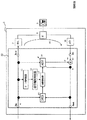
図1は、上述したような位置に設けられた第1の実施形態のエコーキャンセラ12の詳細構成を周囲の構成と共に示すブロック図であり、図5との同一、対応部分には同一符号を付して示している。なお、第1の実施形態のエコーキャンセラ12は、入出力信号がデジタル信号であるものである。
FIG. 1 is a block diagram showing the detailed configuration of the
図1において、第1の実施形態のエコーキャンセラ12は、入出力端子として、受信入力端子Rin、受信出力端子Rout、送信入力端子Sin及び送信出力端子Soutを有する。エコーキャンセラ12は、加算器13、ダブルトーク検出器(DTD)14、トーン性判定器15、信号種別判定器16、係数制御器17及び適応フィルタ(ADF)18を有する。
In FIG. 1, the
加算器13は、送信入力端子Sinからの信号から擬似エコー信号y’を減算してエコー成分を除去するものである。
The
ダブルトーク検出器14は、受信入力端子Rinからの信号、及び、加算器13の出力信号に基づいて、ダブルトーク状態などのトーク状態を検出するものである。第1の実施形態のダブルトーク検出器14は、係数制御器17からの制御信号によって、内部状態をクリアすることも行う。
The
トーン性判定器15は、受信入力端子Rinからの入力された信号がトーン性を有する信号か否かを判定するものである。トーン性を有する信号とは、呼制御のための各種トーン(例えばダイヤルトーン)のような所定周期を有する繰り返し波形信号をいう。トーン性判定器15は、トーン性を有するか否かを判定できるものであればどのような方式のものであっても良いが、例えば、特開2000−295641号公報に記載のものを適用し得る。
The
信号種別判定器16は、トーン性判定器15がトーン性を有する信号と判定した場合に、その信号がいずれかの呼制御信号(呼制御に係るトーン信号)かを判定するものである。判定方法については、動作説明の項で明らかにする。
The
係数制御器17は、ダブルトーク検出器14の検出結果や信号種別判定器16の判定結果に応じて、適応フィルタ18におけるフィルタ係数の更新を実行するか否かや、フィルタ係数をクリアするなどを制御するものである。
The
適応フィルタ18は、受信入力端子Rinからの入力信号と内部のフィルタ係数とから、擬似エコー信号y’を生成して加算器13に減算入力として与えるものである。また、適応フィルタ18は、エコー除去残差信号eをも考慮しながら、フィルタ係数を更新するものである。但し、適応フィルタ18は、係数制御器17によって、フィルタ係数のクリアが指示されたときにはフィルタ係数のクリアを行う。
The
(A−2)第1の実施形態の動作
次に、第1の実施形態のエコーキャンセラ12の動作を、このエコーキャンセラ12を含む電話通信システムの動作と共に説明する。
(A-2) Operation of the First Embodiment Next, the operation of the
発呼側電話機9が、電話機1の話者(図示せず)に電話しようと受話器を持ち上げると、電話機9に向かってダイヤルトーンが出力される。ダイヤルトーンは、例えば、図5のVoIP端末6とIP網5の間の図示しないIPゲ−トウェイ装置から出力され、受信入力端子Rinに入力されることもあり、また、VoIP端末6の内部に設けられたトーン発生器(図示せず)から受信入力端子Rinに入力されることもある。以下では、図示しないIPゲ−トウェイ装置から出力された後、受信入力端子Rinに入力されるとして説明する。ダイヤルトーンは、いわゆる受話器を持ち上げたときに聞こえる「ツー」音であり、日本においては周波数400Hzのトーン信号である。
When the calling
受信入力端子Rinから入力された受信信号(トーン信号や通話信号など;デジタル信号)は、ダブルトーク検出器14、トーン性判定器15、受信出力端子Rout及び適応フィルタ18に入力される。
A reception signal (tone signal, speech signal, etc .; digital signal) input from the reception input terminal Rin is input to the
受信入力端子Rinから入力され、受信出力端子Routからそのまま出力された受信信号(デジタル信号)は、D/A変換器7によってアナログ信号に変換され、そのアナログ信号はハイブリッド回路8を介して電話機9に出力される。しかし、変換されたアナログ信号の一部はハイブリッド回路8で反射される。ハイブリッド回路8で反射された信号は、A/D変換器10を経由して、送信入力端子Sinに入力される。
A reception signal (digital signal) input from the reception input terminal Rin and output as it is from the reception output terminal Rout is converted into an analog signal by the D /
送信入力端子Sinに入力された信号は、加算器13を経由して適宜エコー成分が除去された後、ダブルトーク検出器14、適応フィルタ18及び送信出力端子Soutに入力される。送信出力端子Soutからは、IP網5側に向かって信号が出力される。
The signal input to the transmission input terminal Sin is input to the
トーン性判定器15に入力された信号は、トーン性判定器15によって、トーン性の信号か否かが判定される。トーン性判定器15は、入力された信号がトーン性信号であればトーン性ありの信号TONを、そうでなければ、トーン性なしの信号TOFFを信号種別判定器16に出力すると共に、入力信号をそのまま信号種別判定器16に出力する。トーン性判定器15に入力された信号がダイヤルトーンであれば、通常は、トーン性判定器15によってトーン性ありと判定される。
It is determined by the
信号種別判定器16においては、例えば、公知のFFT(高速フーリエ変換)や公知のゼロクロス法等によって入力信号の周波数を分析する。以下では、ゼロクロス法、すなわち、信号振幅の水平軸との交差数検出の方法を用いているとして説明する。
In the signal
ここで、デジタルサンプリング周波数を16kHzとすると、入力信号波形の同一方向へのゼロ交差する周期(間隔)のサンプル数T1が、(4)式を満たす場合には、入力信号が400Hzの信号であると判定する。 Here, assuming that the digital sampling frequency is 16 kHz, the input signal is a signal of 400 Hz when the number of samples T1 of the period (interval) that crosses zero in the same direction of the input signal waveform satisfies the equation (4). Is determined.
40−M1≦T1≦40+M1 …(4)
(4)式における40は、16kHz/400Hzであり、入力信号が正弦波信号のようなトーン信号の場合の同一方向(負から正、又は、正から負のいずれか一方)のゼロ交差の周期のサンプル数になっている。M1は、許容する誤差範囲を規定するパラメータであり、例えば、5を用いることができる。すなわち、ゼロ交差してから次にゼロ交差するまでのサンプル数T1が(4)式を満たすときに、入力信号が400Hzの信号であると判定する。他の周波数fの信号に関しても、ゼロ交差の間隔が16000/fサンプルになることから、同様に周波数を検出する式を定めておけば良い。(5)式は、周波数fの信号に関する、(4)式に対応する式である。
40−M1 ≦ T1 ≦ 40 + M1 (4)
40 in the equation (4) is 16 kHz / 400 Hz, and the period of zero crossing in the same direction (either negative to positive or positive to negative) when the input signal is a tone signal such as a sine wave signal. The number of samples. M1 is a parameter that defines an allowable error range. For example, 5 can be used. That is, when the number of samples T1 from the zero crossing to the next zero crossing satisfies the equation (4), it is determined that the input signal is a signal of 400 Hz. For signals of other frequencies f, the zero crossing interval is 16000 / f samples, and thus an equation for detecting the frequency may be determined in the same manner. The expression (5) is an expression corresponding to the expression (4) regarding the signal of the frequency f.
16000/f−M1≦T1≦16000/f+M1 …(5)
信号種別判定器16は、トーン性判定器15から与えられたトーン性の有無信号TON、TOFFと、周波数分析によって得た周波数情報とから、入力信号が既知の呼制御信号であるか否かを判定し、呼制御信号と判定した際には、係数制御器17及びダブルトーク検出器14に対して、係数リセット信号RSTを出力する。信号種別判定器16は、例えば、トーン性ありの信号TONが入力され、周波数分析によって得た周波数情報が所定周波数(例えば、400Hz又は2100Hz)のときに係数リセット信号RSTを出力する。例えば、ダイヤルトーンの入力時には、所定周波数400Hzを有するので、信号種別判定器16は、ダイヤルトーンという種別の特定はなされなくても、係数リセット信号RSTを出力する。
16000 / f−M1 ≦ T1 ≦ 16000 / f + M1 (5)
The
図6は、呼制御信号(トーン信号)と周波数との関係を示す説明図である。ダイヤルトーン(DT)、リングバックトーン(RBT)、ビジートーンなどは400Hzのトーン信号であり、FAX通信開始トーンは2100Hzのトーン信号である。そのため、信号種別判定器16は、例えば、内部メモリに400、2100を記憶しておき、(5)式を適用する際に、記憶されている400又は2100を周波数fとして読み出して、(5)式に従った判定を行う。図6では、2種類の所定周波数を示しているが、3種類以上の所定周波数を記述しておくようにしても良い。
FIG. 6 is an explanatory diagram showing the relationship between the call control signal (tone signal) and the frequency. The dial tone (DT), ringback tone (RBT), busy tone, and the like are tone signals of 400 Hz, and the FAX communication start tone is a tone signal of 2100 Hz. Therefore, for example, the signal
係数制御器17は、係数リセット信号RSTが入力されると、適応フィルタ18の係数をクリアする信号CL_Tを適応フィルタ18に出力する。なお、係数制御器17は、係数リセット信号RSTが入力されないときにはクリア指示信号CL_Tを出力しない。クリア指示信号CL_Tを受けた適応フィルタ18は、フィルタ係数をクリアする。適応フィルタ18は、クリア指示信号CL_Tが到来しなくなったときに、フィルタ係数の更新を初期状態から実行し直す。
When the coefficient reset signal RST is input, the
また、クリア指示信号CL_T信号は上述のようにダブルトーク検出器14にも与えられる。ダブルトーク検出器14は、ERLEを用いてダブルトークの検出を行うものであるが、クリア指示信号CL_Tが与えられると、内部状態をクリアする。
The clear instruction signal CL_T signal is also given to the
以上のように、受信入力端子Rinに入力された信号がDTなどの呼制御信号のときには、適応フィルタ18の係数がクリアされるようになっている。実際、電話機9側の発呼側話者がダイヤル操作をおえて、人間音声の信号が通話経路を流れ始めると、信号種別判定器16からは係数リセット信号RSTが出力されなくなり、これにより、適応フィルタ18は、係数クリアの望ましい初期状態からエコー経路の推定を開始することができ、迅速に、エコー経路推定を実行することができる。また、ダブルトーク検出器14は、クリアされた望ましい初期状態から収束を始めた適応フィルタ18の打ち消し加算出力と、受信入力端子Rinからの入力信号を用いてERLEを計算して正しいダブルトーク検出を実施することができる。
As described above, when the signal input to the reception input terminal Rin is a call control signal such as DT, the coefficient of the
(A−3)第1の実施形態の効果
第1の実施形態によれば、通話開始時などに不可避的に発生する呼制御信号を検出し、適応フィルタの係数をクリアすると共に、ダブルトーク検出器の内部状態をクリアするようにしたので、トーン信号(呼制御トーン)による誤収束を防止し、望ましい初期状態からエコーキャンセラの適応フィルタの更新を開始させることができ、迅速にエコー経路推定を実行し、ダブルトークによる性能劣化も少ないエコーキャンセラを提供することができる。ここで、エコー経路の初期遅延が短い場合であったにしても、エコーのない良好な通話を実現することができる。
(A-3) Effect of First Embodiment According to the first embodiment, a call control signal inevitably generated at the start of a call is detected, the coefficient of the adaptive filter is cleared, and double talk detection is performed. Since the internal state of the device is cleared, misconvergence due to tone signals (call control tones) can be prevented, and the update of the echo canceller's adaptive filter can be started from the desired initial state. It is possible to provide an echo canceller that is executed and has little performance degradation due to double talk. Here, even if the initial delay of the echo path is short, a good call without echo can be realized.
(B)第2の実施形態
次に、本発明によるエコーキャンセラを、VoIP端末に設けられるエコーキャンセラに適用した第2の実施形態を、図面を参照しながら説明する。
(B) Second Embodiment Next, a second embodiment in which the echo canceller according to the present invention is applied to an echo canceller provided in a VoIP terminal will be described with reference to the drawings.
第2の実施形態のエコーキャンセラは、従来技術の上述した課題1、2、3に鑑みてなされたものである。
The echo canceller of the second embodiment has been made in view of the above-described
また、第1の実施形態を適用した場合において、VoIP端末6内の以下の位置に図1で図示していないトーン検出器が設けられた場合に生じる課題に鑑みてなされたものである。なお、以下のような位置に、トーン検出器が設けられていなければ、第1の実施形態は有効に機能するものである。
Further, in the case where the first embodiment is applied, the present invention has been made in view of problems that occur when a tone detector (not shown in FIG. 1) is provided in the following position in the
上述した図1(第1の実施形態)のように、VoIP端末6内にエコーキャンセラ12を配置した場合、送信出力端子Soutの出力側に、トーン性判定器15とは無関係に、図示しないトーン検出器を設けることが多い。その理由は、電話機9から入力されるプッシュボタン信号(DTMF信号:PB信号)などを検出するためである。しかし、第1の実施形態のように、受信入力端子Rinからの出力信号についてトーン性の信号として検出し、エコーキャンセラをリセットしてエコー除去しないように動作させると、下記のような不都合が発生する。
When the
例えば、受信入力端子Rinから入力されたダイヤルトーン信号の一部は、受信出力端子Rout、D/A変換器7、ハイブリッド回路8、A/D変換器10を経由して、送信入力端子Sinにエコーy1として入力される。上述したように、電話機9からプッシュボタン信号であるDTMF信号s1が出力されたとき、ハイブリッド回路8でエコーy1とDTMF信号s1が合算され、A/D変換器10を経由してエコーキャンセラ12内に入力されるが、エコー除去なしのまま送信出力端子Soutに出力される。その結果、上述したトーン検出器は、DTMF信号以外の余分なエコー信号y1に妨害され、プッシュボタン番号をうまく検出できないなどの不都合が発生してしまう。このような問題は、上述のエコーによる不都合を想定していないVoIP端末では頻発し、受話器を持ち上げ、ダイヤルトーン(ツー音)を聞いている状態で、ダイヤルボタンを押しても、なかなか電話番号を認識させられないという現象を引き起こす。最悪の場合、電話がかけられないなどの深刻な問題として発現する。
For example, a part of the dial tone signal input from the reception input terminal Rin is sent to the transmission input terminal Sin via the reception output terminal Rout, the D /
第2の実施形態は、このような課題にも鑑みたものであり、第1の実施形態と同様な効果に加え、受信入力端子Rinからダイヤルトーン等の信号が入力されていても、電話機9からのプッシュボタン信号を検出できるようなエコーキャンセラを提供することをも目的としている。
The second embodiment has been made in view of such a problem, and in addition to the same effects as those of the first embodiment, even if a signal such as a dial tone is input from the reception input terminal Rin, the
(B−1)第2の実施形態の構成
図7は、第2の実施形態のエコーキャンセラ12Aの詳細構成を周囲の構成と共に示すブロック図であり、第1の実施形態に係る上述した図1との同一、対応部分には同一符号を付して示している。
(B-1) Configuration of Second Embodiment FIG. 7 is a block diagram showing the detailed configuration of the
図7において、第2の実施形態のエコーキャンセラ12Aは、第1の実施形態と同様に、加算器13、ダブルトーク検出器14、トーン性判定器15、信号種別判定器16A及び適応フィルタ18を有する。一方、第2の実施形態のエコーキャンセラ12Aは、係数制御器17を備えず、代わりに、帯域阻止フィルタ(NF)21、22が設けられており、また、信号種別判定器16Aも、第1の実施形態のものとは多少異なる処理を行うものである。
In FIG. 7, the
第2の実施形態の信号種別判定器16Aは、呼制御信号か否かでなく、入力信号の具体的な呼制御信号の種別をも判定するものである。例えば、同じ400Hzのダイヤルトーンとビジートーンを区別して判定するものである。第2の実施形態の信号種別判定器16Aは、例えば、FFTなどによって得たスペクトラムパターンを基準のスペクトラムパターンと照合したり、入力信号の波形パターンをダイナミックレンジを揃えた後に基準の波形パターンと照合したりなどして、呼制御信号の具体的な種別をも判定する。信号種別判定器16Aは、入力信号がトーン信号であって具体的な種別を得たときには、帯域阻止フィルタ21及び22に種別情報を与えるものである。
The signal
帯域阻止フィルタ21は、送信入力端子Sinと加算器16との間に設けられたものである。一方、帯域阻止フィルタ22は、受信入力端子Rinとダブルトーク検出器14の間、及び、受信入力端子Rinと適応フィルタ18の間に設けられたものである。
The
各帯域阻止フィルタ21、22は、信号種別判定器16Aから種別情報が与えられたときには、その種別情報で定まる周波数成分の通過を阻止するものである。すなわち、帯域阻止フィルタ21、22は、通過阻止帯域などを可変し得る帯域阻止フィルタである。
Each of the band rejection filters 21 and 22 is configured to prevent passage of a frequency component determined by the type information when the type information is given from the signal
(B−2)第2の実施形態の動作
次に、第2の実施形態のエコーキャンセラ12Aの動作を、第1の実施形態との相違点を中心に説明する。
(B-2) Operation of the Second Embodiment Next, the operation of the
第2の実施形態の信号種別判定器16Aは、入力信号の具体的な種別を判定すると、その判定結果、すなわち、信号の種別を表す信号KIND_TONEを両帯域阻止フィルタ21及び22に出力する。信号種別判定器16Aは、入力信号が非トーン性の信号の場合にはなにも出力しない。
When the signal
図8は、信号種別判定器16Aの判定結果と出力信号KIND_TONEとの関係の説明図である。信号種別判定器16Aは、図8に示すような関係を表す情報を内部記憶しており、判定結果に応じた値を有する信号KIND_TONEを出力する。図8の例の場合、KIND_TONE=1はダイヤルトーンを表している。信号KIND_TONEの値は、周波数と信号の種類を表すものであればどのような体系に従っているものであっても良く、図8とは異なるが、例えば、周波数を直接表す数値400等を直接信号KIND_TONEの出力値とするようにしても良い。なお、入力信号が非トーン性の信号である場合にも、非トーン性の信号であることを表す値(例えば、0)を有する信号KIND_TONEを出力するようにしても良い。
FIG. 8 is an explanatory diagram of the relationship between the determination result of the
信号種別判定信号KIND_TONEが入力された各帯域阻止フィルタ21、22はそれぞれ、信号KIND_TONEに応じた周波数を阻止するように、入力信号に対し、公知の帯域阻止フィルタ処理を施す。各帯域阻止フィルタ21、22はそれぞれ、信号KIND_TONEがないときには入力信号を通過させる。 Each of the band rejection filters 21 and 22 to which the signal type determination signal KIND_TONE is input performs a known band rejection filter process on the input signal so as to block the frequency corresponding to the signal KIND_TONE. Each of the band rejection filters 21 and 22 allows the input signal to pass when there is no signal KIND_TONE.
帯域阻止フィルタ21、22は、予め用意した複数のフィルタ、すなわち、予め定めた周波数(例えば400Hz)やその他の周波数を阻止する帯域阻止フィルタの中から一つ又は複数を選択して信号KIND_TONEで指示された周波数を阻止するフィルタを実現するようにしても良く、また、入力された周波数から適宜その都度適応的に周波数阻止フィルタが構成されるようにしても良い。適応的に帯域阻止フィルタ21、22を実現する方法について説明すると、例えば、いま信号KIND_TONEが指示する阻止周波数が400Hzであり、サンプリング周波数が16kHzであるとすると、入力信号を40(=16kHz/400Hz)サンプルだけ遅延させた信号を反転し(400Hz周期に相当する)、遅延なしの入力信号と加算することにより400Hzトーンを除去するフィルタを実現することができる。要は、信号種別や周波数の情報に応じて、所定の周波数を除去するフィルタが実現できれば、どのような方法を用いても良い。上述のように帯域阻止フィルタ21、22では入力された信号種類に呼制御信号の通過を阻止する。 The band rejection filters 21 and 22 select one or more of a plurality of filters prepared in advance, that is, a band rejection filter that blocks a predetermined frequency (for example, 400 Hz) or other frequencies, and designates it with a signal KIND_TONE. A filter that blocks the input frequency may be realized, or a frequency blocking filter may be configured adaptively from time to time based on the input frequency. A method of adaptively realizing the band rejection filters 21 and 22 will be described. For example, if the rejection frequency indicated by the signal KIND_TONE is 400 Hz and the sampling frequency is 16 kHz, the input signal is 40 (= 16 kHz / 400 Hz). A filter that removes the 400 Hz tone can be realized by inverting the signal delayed by the sample (corresponding to a period of 400 Hz) and adding it to the input signal without delay. In short, any method may be used as long as a filter that removes a predetermined frequency can be realized in accordance with signal type and frequency information. As described above, the band rejection filters 21 and 22 prevent the call control signal from passing through the input signal type.
帯域阻止フィルタ21からの出力信号は加算器13に入力され、適宜、エコー除去がなされる。一方、帯域阻止フィルタ22からの出力信号はダブルトーク検出器14及び適応フィルタ18に入力され、適宜、ダブルトーク状態の検出や擬似エコー信号y’の形成に用いられる。
The output signal from the
仮に、受信入力端子Rinからの入力信号が信号種別判定器16Aでトーン信号と判定されたときには、帯域阻止フィルタ22でそのトーン信号が除去されるので、適応フィルタ18とダブルトーク検出器14には何も入力されないと同じである。このとき、電話機9からDTMF信号s1がハイブリッド回路8に向かって出力されても、帯域阻止フィルタ21で帯域阻止された後の信号は信号s1だけとなって加算器13に入力される。一方、受信入力端子Rinからのトーン信号は帯域阻止フィルタ22によって阻止され、適応フィルタ18及びダブルトーク検出器14には何も入力されない。すなわち、このとき、適応フィルタ18への入力信号x(n)=0となり、上述した(1)式は、(6)式のように表すことができ、係数更新は、実質上停止される。
If the input signal from the reception input terminal Rin is determined to be a tone signal by the signal
hk(n+1)=hk(n+1)+0 …(6)
また、このような係数更新の制御に加えて、(1)式の右辺第2項の分母=0となって割算が発散しないように、分母である入力信号の2乗総和≦MIN(dBm0)×積和数のときには更新を停止するようにしている(dBm0の0dBm0基準値=0dBm0は公知のITU(国際電気通信連合)−T(通信部門)規格勧告G.711に記載の通り)。例えば、MIN=−50dBm0を適用できるが、これに限定されず、適宜設定すれば良い。
h k (n + 1) = h k (n + 1) +0 (6)
In addition to such coefficient update control, the sum of the squares of the input signals as denominators ≦ MIN (dBm0) so that the denominator of the second term on the right side of equation (1) = 0 and division does not diverge. ) × multiply-sum number, updating is stopped (0 dBm0 reference value of dBm0 = 0 dBm0 is as described in the well-known ITU (International Telecommunication Union) -T (communication sector) standard recommendation G.711). For example, MIN = −50 dBm0 can be applied, but is not limited to this and may be set as appropriate.
上述のように帯域阻止フィルタ21、22を用いると、帯域阻止フィルタ21、22が受信入力端子Rinからのトーン信号及びトーンよるエコーを阻止するので、適応フィルタ18の係数更新を手続き上、相当長時間実行したとしても、実質の更新量が0になり、係数の値自体は更新されず変化しない。また、参照入力が0である適応フィルタ18は何も出力しないので、加算器13に対して余分な擬似エコーy’を出力しない。従って、加算器13に入力されたDTMF信号s1は一切の劣化を受けることなく、エコーy1だけを除去されて送信出力端子Soutに出力される。送信出力端子Soutからの出力信号(DTMF信号)は、図示しないトーン検出器で正しく検出される。
When the band rejection filters 21 and 22 are used as described above, the band rejection filters 21 and 22 block the tone signal from the reception input terminal Rin and the echo due to the tone. Even if it is executed for a time, the actual update amount becomes 0, and the coefficient value itself is not updated and does not change. Further, since the
また、トーン信号での誤収束がないので、ダブルトーク検出器14の内部状態も乱れることがなく、トーンに続く通常音声でのダブルトーク検出も精度良く行ってエコーを除去することができる。
In addition, since there is no false convergence in the tone signal, the internal state of the
(B−3)第2の実施形態の効果
以上説明したように、第2の実施形態によれば、第1の実施形態と同様な効果に加え、以下の効果を奏することができる。受信入力端子Rinからトーン信号があり、収容している電話機が反対方向にDTMF信号などのトーン信号を出力しても、エコーキャンセラ出力を用いたトーン検出器が正しくDTMF信号を識別して電話をかけることができ、エコー経路の初期遅延の大小にかかわりなくトーン信号での誤収束がないので、ダブルトーク検出器の内部状態も乱れることがなく、トーンに続く通常音声でのダブルトーク検出も精度良く行ってエコーを除去することができる。
(B-3) Effects of Second Embodiment As described above, according to the second embodiment, the following effects can be obtained in addition to the same effects as those of the first embodiment. Even if there is a tone signal from the receiving input terminal Rin, and the accommodating telephone outputs a tone signal such as a DTMF signal in the opposite direction, the tone detector using the echo canceller output correctly identifies the DTMF signal and makes a call. Because there is no misconvergence in the tone signal regardless of the initial delay of the echo path, the internal state of the double talk detector is not disturbed, and the double talk detection in the normal voice following the tone is also accurate. You can go well and remove the echo.
(C)第3の実施形態
次に、本発明によるエコーキャンセラを、構内交換装置に設けられるエコーキャンセラに適用した第3の実施形態を、図面を参照しながら説明する。
(C) Third Embodiment Next, a third embodiment in which the echo canceller according to the present invention is applied to an echo canceller provided in a private branch exchange will be described with reference to the drawings.
第3の実施形態のエコーキャンセラは、内線交換が発生するPBX接続のようなエコー経路切り替えがある大規模系に適用したとき、エコー打消し不可能状態から自動的に脱出して、エコーのない通話を実現することを達成しようとしたものであり、従来技術の上述した課題1〜4に鑑みてなされている。
The echo canceller of the third embodiment, when applied to a large-scale system with echo path switching such as PBX connection in which extension exchange occurs, automatically escapes from the state where echo cancellation is not possible and has no echo. This is intended to achieve a telephone call, and has been made in view of the above-described
(C−1)第3の実施形態の構成
図9は、第3の実施形態のエコーキャンセラの詳細構成を、周囲の構成と共に示すブロック図であり、既述した第1、第2の実施形態に係る図1、図7との同一、対応部分には同一、対応符号を付して示している。
(C-1) Configuration of Third Embodiment FIG. 9 is a block diagram showing the detailed configuration of the echo canceller of the third embodiment together with the surrounding configuration, and the first and second embodiments already described. The same and corresponding parts as those in FIGS. 1 and 7 are indicated by the same reference numerals.
図9において、第3の実施形態のエコーキャンセラ12Bは、内線転送機能を有する構内交換装置(PBX)6Bに設けられている。構内交換装置6Bは、例えば、転送前後の電話機9−1、9−2を収容し、4線2線変換するハイブリッド回路8−1、8−2と、電話機9−1又は9−2へ向かうデジタル信号をデジタル/アナログ変換するデジタル/アナログ変換器(D/A変換器)7、電話機9−1又は9−2が出力した信号をアナログ/デジタル変換するアナログ/デジタル変換器(A/D変換器)10と、D/A変換器7の出力信号をハイブリッド回路8−1又は8−2に与えるスイッチ30−1と、ハイブリッド回路8−1又は8−2から出力された信号をA/D変換器10に与えるスイッチ30−2と、第3の実施形態のエコーキャンセラ12Bとを有している。なお、スイッチ30−1及び30−2は連動して切替動作するものである。
In FIG. 9, the echo canceller 12B of the third embodiment is provided in a private branch exchange (PBX) 6B having an extension transfer function. The private branch exchange 6B, for example, accommodates the telephones 9-1 and 9-2 before and after the transfer, and goes to the hybrid circuits 8-1 and 8-2 that perform 4-wire 2-line conversion, and the telephones 9-1 or 9-2. Digital / analog converter (D / A converter) 7 for digital / analog conversion of digital signal, analog / digital converter (A / D conversion) for analog / digital conversion of signal output from telephone set 9-1 or 9-2 10), the switch 30-1 for supplying the output signal of the D /
第3の実施形態のエコーキャンセラ12Bは、加算器13、ダブルトーク検出器14B、トーン性判定器15B、信号種別判定器16B、係数制御器17B、適応フィルタ18、帯域阻止フィルタ21、22、フィルタ状態判定器31及びエコー消去量計算器(ACANC)32を有する。
The echo canceller 12B according to the third embodiment includes an
加算器13、適応フィルタ18及び帯域阻止フィルタ21、22は第2の実施形態のものと同様である。
The
第3の実施形態のトーン性判定器15Bは、既述した実施形態の機能に加え、DTMF信号のような2種類の合成トーン信号をも判定し得るものである。
The tone
第3の実施形態の信号種別判定器16Bは、トーン性判定器15Bの判定結果を利用し、DTMF信号のような2種類の合成トーン信号の種別も判定し得るものである。信号種別判定器16Bは、また、トーン信号の終了も判定するものである。
The signal type determiner 16B of the third embodiment can also determine the types of two types of synthesized tone signals such as DTMF signals, using the determination result of the
エコー消去量計算器32は、加算器13の入出力信号から、言い換えると、エコー成分を有する入力信号と、エコー除去動作がなされた後の出力信号とから、エコー消去量を計算するものである。
The echo
フィルタ状態判定器31は、信号種別判定器16Bの判定結果と、エコー消去量計算器32の計算結果とから、適応フィルタ18の状態を判定するものである。
The
第3の実施形態の係数制御器17Bは、フィルタ状態判定器31による判定結果から、適応フィルタ18の係数更新の停止や係数のクリアなどの制御内容を定めるものである。
The
第3の実施形態のダブルトーク検出器14Bは、係数制御器17Bによる制御内容と、自己におけるダブルトークの検出結果とに応じて、適応フィルタ18に対する係数更新を制御するものである。
The
(C−2)第3の実施形態の動作
次に、第3の実施形態のエコーキャンセラ12Bの動作を説明する。以下では、着呼側電話機9−1から着呼側の他の電話機9−2に切り替える転送が発生するときの様子を説明する。ここで、転送が発生する前後の説明であるので、図示しない発呼電話機と着呼側電話機9−1は既に一旦、通話している状態であるとして説明をする。
(C-2) Operation of the Third Embodiment Next, the operation of the echo canceller 12B of the third embodiment will be described. In the following, a description will be given of a situation in which a transfer for switching from the called telephone 9-1 to another telephone 9-2 on the called side occurs. Here, since the description is before and after the occurrence of the transfer, it is assumed that the calling telephone and the called telephone 9-1 (not shown) have already made a call.
まず、図示しない発呼側電話機から出力された音声信号は、エコーキャンセラ12Bの前段の図示しないA/D変換器でデジタル信号に変換されて受信入力端子Rinに入力される。受信入力端子Rinに入力された信号は、帯域阻止フィルタ22、トーン性判定器15Bに与えられると共に、受信出力端子Routからそのまま出力されてD/A変換器7に入力される。
First, a voice signal output from a calling telephone (not shown) is converted into a digital signal by an A / D converter (not shown) in the previous stage of the echo canceller 12B and input to the reception input terminal Rin. The signal input to the reception input terminal Rin is provided to the
D/A変換器7でアナログ信号に変換された信号は、スイッチ30−1を経由してハイブリッド回路8−1に入力され、このハイブリッド回路8−1を介して電話機9−1に与えられると共に、信号の一部はハイブリッド回路8−1で反射され、エコー信号y1となる。エコー信号y1は、スイッチ30−2を経由してA/D変換器10に与えられ、再びデジタル信号に変換されてエコーキャンセラ12Bの送信入力端子Sinに入力される。
The signal converted into an analog signal by the D /
送信入力端子Sinに入力された信号は、帯域阻止フィルタ21に入力される。各帯域阻止フィルタ21、22では、後述するように、信号種別判定器16Bの出力に応じたトーン性信号を除去し、トーン除去後の信号Sin_ACをエコー消去量計算器32に出力すると共に、加算器13に出力する。加算器13はトーン除去後の信号Sin_ACと擬似エコーy’を加算してエコーを除去する。加算器13からの出力信号resは、ダブルトーク検出器14B、エコー消去量計算器32に入力され、また、送信出力端子Soutから、図示しない遠方の発呼側電話機に向かって送出される。
A signal input to the transmission input terminal Sin is input to the
ここで、エコー消去量計算器32の動作について説明する。エコー消去量計算器32は、例えば、(4)式に従って、エコー消去量ACANC(n)を計算する。(4)式において、nは第n回目の計算値であることを表している。
(4)式では、直接Sin_AC(n)、res(n)の自乗比を対数計算したものであるが、信号のおおまかな振る舞いに重点をおき、緩やかな特性の変化を監視するためであれば、(5)式のように、Sin_AC、resを所定サンプル数(例えば160サンプル)ずつ集め、その総和をとってから両方の比をとり、対数計算するなどしても良い。また、自乗ではなく絶対値を用いるようにしても良い。(5)式において、Mは平均したいサンプル数であり、例えば160などにすれば良いが、このサンプル数に限定されるものではない。
要は、加算器13の前後の信号のレベル比やパワー比を計算する方法であれば、エコー消去量計算器32による計算方法はどのような方法であっても良い。(4)式で得られたエコー消去量ACANC(n)は、加算器13の前後の信号の自乗を対数比で計算したものであり、エコーキャンセラ12Bの収束に従って加算器13からの出力信号resが小さくなると、エコー消去量ACANC(n)の値は大きくなっていく。エコー消去量ACANC(n)の初期値としては0を適用できるが、これに限定されるものではない。エコー消去量計算器32は、計算したエコー消去量ACANC(n)をフィルタ状態判定器31に入力する。
In short, as long as the level ratio and power ratio of the signals before and after the
この第3の実施形態では、エコーの除去量を計算するために、加算器13の前後の信号を用いてエコー消去量計算器32によってエコー消去量を計算するようにしたが、別な方法の例を挙げれば、以下の通りである。受信入力端子Rin及び受信出力端子Rout間の任意の1点と、加算器13の直後の点から信号をとり、エコー経路の減衰分を含んだエコー減衰量を計算するようにしても良い。
In the third embodiment, the echo cancellation amount is calculated by the echo
フィルタ状態判定器31には、エコー消去量計算器32からエコー消去量ACANC(n)が与えられ、また、信号種別判定器16Bから後述する帯域阻止フィルタ制御信号KIND_TONE、トーン終了信号TENDが与えられる。
The filter
以下、第3の実施形態のトーン性判定器15B及び信号種別判定器16Bの動作を説明する。
Hereinafter, operations of the
信号種別判定器16Bにはトーン性判定器15Bの出力信号が入力されている。第3の実施形態のトーン性判定器15Bは、第2の実施形態のトーン性判定器の機能に加え、DTMF信号、すなわち、2種類の合成トーン信号を判定できるようになされている。トーン性判定器15Bは、2種類の合成トーン信号を判定できるように、予め信号を大まかな二つの帯域に分けるようになされている。これは、DTMF信号が、高周波数で構成される「高群」と低周波数で構成される「低群」の2種のトーンを合成して生成されていることに基づいている。
The output signal of the
この第3の実施形態においては、トーン性判定器15Bは、「高群」を分離するために、1000Hzから1700Hzを通過域にしているバンドパスフィルタと、「低群」を分離するために、600Hzから980Hzを通過域にしているバンドパスフィルタと、第1、第2の実施形態で説明したような400Hz近辺の「呼制御信号群」を分離するための0Hzから500Hzを通過域にしているバンドパスフィルタとを内蔵しており、トーン性判定器15Bは、これら各バンドパスフィルタによる帯域分割後の信号に対して、第1の実施形態で説明したと同様のゼロクロスによるトーン周波数の判定を行うようになされている。
In the third embodiment, the
第3の実施形態の信号種別判定器16Bは、「呼制御信号群」の周波数帯域の信号に関しては、上述した第2の実施形態のように信号種別を判定し(図8参照)、「高群」及び「低群」の周波数帯域を共に有する信号に関しては、内部に記憶している図10に示すような入力と判定結果と出力との関係情報に基づき、信号の種別を判定する。なお、「呼制御信号群」と「高群」とが検出された場合や、「呼制御信号群」と「低群」とが検出された場合や、「呼制御信号群」と「高群」と「低群」とが検出された場合などでは、トーン性の信号ではないと取り扱うようにしても良いが、これに限定されるものではない。 The signal type determination unit 16B of the third embodiment determines the signal type for signals in the frequency band of the “call control signal group” as in the second embodiment described above (see FIG. 8). For a signal having both the “group” and “low group” frequency bands, the type of the signal is determined based on the relation information between the input, the determination result, and the output as shown in FIG. In addition, when "call control signal group" and "high group" are detected, when "call control signal group" and "low group" are detected, "call control signal group" and "high group" ”And“ low group ”may be handled as not being a tone signal, but the present invention is not limited to this.
信号種別判定器16Bは信号種別を判定すると、その判定結果、すなわち、信号の種別を表す信号KIND_TONEを帯域阻止フィルタ21、22とフィルタ状態判定器31とに出力する。信号KIND_TONEは、例えば、信号を識別する値(番号)と信号種類とが図8及び図10のように関連付けされているなど、周波数と信号の種類が対応付けられるものであれば、どのような値の体系をもっているものであっても良い。
When the signal type determiner 16B determines the signal type, it outputs the determination result, that is, the signal KIND_TONE indicating the signal type to the band rejection filters 21 and 22 and the
図8及び図10の例であれば、KIND_TONE=1であればダイヤルトーン(DT)を表し、KIND_TONE=5であればDTMF信号の「1」を表している。 In the example of FIGS. 8 and 10, when KIND_TONE = 1, it represents a dial tone (DT), and when KIND_TONE = 5, it represents “1” of the DTMF signal.
信号種別判定器16Bから信号KIND_TONEが入力された各帯域阻止フィルタ21、22はそれぞれ、信号KIND_TONEに応じて定まる周波数を阻止するように、入力信号に対し、公知の帯域阻止フィルタ処理を施す。帯域阻止フィルタ21、22の振る舞いは、第2の実施形態と同様であるが、この第3の実施形態の場合、信号KIND_TONEがDFMF信号を指示しているときに、2種類の信号を除去する点が第2の実施形態のものとは異なっている。例えば、「高群」及び「低群」用に予め用意されている複数の帯域阻止フィルタの中から、それぞれ、信号KIND_TONEに応じて定まる「高群」及び「低群」用のフィルタを選択することで(これらは縦続接続される)DTMF信号に応じた帯域除去を行うようにする。なお、DTMF信号の帯域を阻止する構成方法はこの方法に限定されるものではない。 Each of the band rejection filters 21 and 22 to which the signal KIND_TONE is input from the signal type determination unit 16B performs a known band rejection filter process on the input signal so as to block a frequency determined according to the signal KIND_TONE. The behavior of the band rejection filters 21 and 22 is the same as that of the second embodiment, but in the case of this third embodiment, when the signal KIND_TONE indicates the DFMF signal, two types of signals are removed. The point is different from that of the second embodiment. For example, a filter for “high group” and “low group” determined according to the signal KIND_TONE is selected from a plurality of band rejection filters prepared in advance for “high group” and “low group”, respectively. In this way, the band removal according to the DTMF signal (which is cascaded) is performed. The configuration method for blocking the band of the DTMF signal is not limited to this method.
第3の実施形態の場合、信号種別判定器16Bはフィルタ状態判定器31にも信号KIND_TONEを出力する。また、信号種別判定器16Bは、トーン性判定器15Bからの信号がトーン性あり信号TONからトーン性なし信号TOFFに変化したときに、トーン終了信号TENDをフィルタ状態判定器31に出力する。
In the case of the third embodiment, the signal type determiner 16B also outputs the signal KIND_TONE to the
フィルタ状態判定器31は、信号種別判定器16Bからの出力信号KIND_TONE及びTENDと、エコー消去量計算器32からの出力信号に応じて以下のように動作する。
The
フィルタ状態判定器31は、信号種別判定器16Bから信号KIND_TONEが入力されていないときには、すなわち、受信入力端子Rinからの入力信号がトーン性を持っていない期間では、エコー消去量計算器32からの出力信号を、予め定められた一定時間の間隔で更新しながら保持する。例えば、20msおきに更新保持を実行するが、更新間隔はこれに限定されるものではない。
When the signal KIND_TONE is not input from the signal type determiner 16B, that is, during the period when the input signal from the reception input terminal Rin has no tone property, the
一方、フィルタ状態判定器31は、信号種別判定器16Bから信号KIND_TONEが入力されると、エコー消去量計算器32の出力信号を、下記のように、条件1〜条件4に分類して動作する。
On the other hand, when the signal KIND_TONE is input from the signal type determiner 16B, the
条件1: ACANC(n)≧E_ACANC dB
条件2: ACANC(n)<E_ACANC dB
なお、条件1及び条件2を規定する閾値パラメータE_ACANCとして、例えば、20dBを適用する。但し、閾値パラメータE_ACANCの値は、この値に限定されるものではない。
Condition 1: ACANC (n) ≧ E_ACANC dB
Condition 2: ACANC (n) <E_ACANC dB
Note that, for example, 20 dB is applied as the threshold parameter E_ACANC that defines
条件1が成立するときには、言い換えると、エコー消去量が大きいときには、フィルタ状態判定器31は、係数制御器17Bに適応フィルタ18の係数更新停止を促す信号ADP_STPを出力する。係数制御器17Bは、信号ADP_STPをダブルトーク検出器14Bを経由して適応フィルタ18に出力し、適応フィルタ18の係数更新を停止させる。
When the
トーン信号の期間が終わり、フィルタ状態判定器31に信号種別判定器16Bからの信号TENDが入力されると、一旦、フィルタ状態判定器31は、エコー消去量ACANC(n)の更新保持を停止し、次回のエコー消去量ACANCの更新期間がくるのを待つ。そして、フィルタ状態判定器31は、新たにエコー消去量計算器32でエコー消去量ACANC(n+1)が計算されて、フィルタ状態判定器31に出力されてくると、エコー消去量ACANC(n+1)と先に保持したACANC(n)との比較を行う。
When the period of the tone signal ends and the signal TEND from the signal type determiner 16B is input to the
つまり、トーン性信号がエコーキャンセラ12Bに入力された前後のエコー消去量ACANC(.)を比較する。(.)は任意のnを表す。その後、条件1に続いて、後述する条件3、4の判定を実行し、各々の結果に応じた動作を実行する。
That is, the echo cancellation amount ACANC (.) Before and after the tone signal is input to the echo canceller 12B is compared. (.) Represents an arbitrary n. Thereafter, following
一方、条件2が成立するときには、言い換えると、エコー消去量が小さいときには、フィルタ状態判定器31は、係数制御器17Bに適応フィルタ18の係数更新停止を促す信号ADP_STPを出力しない。
On the other hand, when the
フィルタ状態判定器31は、下記の条件3、4を判定し、結果に応じて各々動作する。なお、条件3及び4におけるΔ1として3dB、Δ2として0dBを適用できるが、これらに限定されるものではない。
The
条件3: Δ2<ACANC(n+1)<ACANC(n)−Δ1
条件4: ACANC(n+1)<Δ2
条件3が成立したときには、言い換えると、トーン性信号が入力されているが、エコー消去量が入力前よりかなり小さいときには、フィルタ状態判定器31は、係数制御器17Bに係数更新促進信号ADP_Fを出力する。
Condition 3: Δ2 <ACANC (n + 1) <ACANC (n) −Δ1
Condition 4: ACANC (n + 1) <Δ2
When the
条件4が成立したときには、言い換えると、エコー除去動作を行うことによりエコー消去量が負になってしまったときには、係数リセット信号ADP_RSTを係数制御器17Bに出力する。
When the
なお、条件3も条件4も成立しないときには、フィルタ状態判定器31は、係数制御器17Bに何ら出力しない。
When neither
上記の条件3に代え、下記の条件3の変形例を適用するようにしても良い。条件3の変形例は、下限固定値Δ2の代わりに、ACANC(n)を利用して、上下にマージン幅を設定したものである。
Instead of the
条件3の変形例:
ACANC(n)−Δ3<ACANC(n+1)<ACANC(n)−Δ1
係数制御器17Bは、フィルタ状態判定器31から係数リセット信号ADP_RSTが入力されたときは、ダブルトーク検出器14Bに対して、リセット信号RSTを出力する。このリセット信号RSTは、ダブルトーク検出器14Bを経由して適応フィルタ18に与えられ、適応フィルタ18は、フィルタ係数をリセットしてから係数更新を再開させる。ここでは、ダブルトーク検出器14Bと適応フィルタ18の両方をリセットさせるようにしたが、適応フィルタ18だけをリセットさせるようにしても良い。
Modification of condition 3:
ACANC (n) −Δ3 <ACANC (n + 1) <ACANC (n) −Δ1
When the coefficient reset signal ADP_RST is input from the filter
また、係数制御器17Bは、フィルタ状態判定器31から係数更新促進信号ADP_Fが入力されたときには、ダブルトーク検出器14Bをリセットさせるが、適応フィルタ18をリセットさせず、係数更新動作を強制的に実行するように制御する。
The
この第3の実施形態では、係数制御器17Bが適応フィルタ18の制御をダブルトーク検出器14Bを経由して行うようにしたが、係数制御器17Bが、適応フィルタ18とダブルトーク検出器14Bを各々制御するようにしても良い。
In the third embodiment, the
第3の実施形態の動作が、従来技術における課題4をどのように解決しているかを説明する。ここでも、課題の項で述べた通り、転送時点のエコーキャンセラの適応フィルタの収束状態の良否と転送前後のエコー経路特性の変化の大小の組み合わせに応じて説明する。
How the operation of the third embodiment solves the
内線転送が発生する最も典型的な例は、図示しない遠端話者(図9の発呼側話者)が転送のための操作をプッシュボタンに対して行い(DTMF信号が出力される)、その後に、構内交換装置(PBX)6Bの転送機能により、着呼側電話機が電話機9−1から電話機9−2に変わるときである。つまり、初めにつながった電話機9−1とは異なる電話機9−2を指定するプッシュボタンを操作し、実際に、別の電話機9−2に再接続されるケースである。 The most typical example in which extension transfer occurs is that a far-end speaker (not shown) (calling speaker in FIG. 9) performs a transfer operation on the push button (DTMF signal is output), Thereafter, the transfer function of the private branch exchange (PBX) 6B changes the telephone on the called side from the telephone set 9-1 to the telephone set 9-2. In other words, this is a case where a push button for designating a telephone 9-2 different from the telephone 9-1 connected first is operated and actually reconnected to another telephone 9-2.
(内線転送ケースA)
内線転送ケースAは、適応フィルタ18の収束が不十分であり、転送前後のハイブリッド回路8−1及び8−2の応答特性がほとんど変わらないケースである。
(Extension transfer case A)
The extension transfer case A is a case in which the convergence of the
転送前に多少の通話が行われ、音声によって適応フィルタ18は収束の途中である。又は、トーン検出までの間に多少の係数擾乱を受けた場合、このケースAにあてはまる。
Some calls are made before transfer, and the
適応フィルタ18の収束が不十分なときにおいて、遠端話者は、例えば、プッシュボタンを操作する(DTMF信号を入力する)などして、異なる電話機9−2に対する接続を要求する。
When the convergence of the
受信入力端子Rinに入力されたDTMF信号は、帯域阻止フィルタ22、トーン性判定器15Bに入力され、また、受信出力端子Routからそのまま出力されてD/A変換器7に与えられる。
The DTMF signal input to the reception input terminal Rin is input to the
トーン性判定器15Bはトーン性を検出する。トーン性判定器15Bの出力に応じて、信号種別判定器16Bから信号KIND_TONEが出力され、各帯域阻止フィルタ21、22において、信号KIND_TONEに応じた周波数の通過が阻止される。
The
この結果、DTMF信号が生じている間は帯域阻止フィルタ21によってDTMF信号は阻止されるので、適応フィルタ18及びダブルトーク検出器14Bには、DTMF信号が入力されていないのと同様な状態になっている。従って、DTMF信号が受信入力端子Rinに長時間入力されても、適応フィルタ18の係数が乱れることはないが、係数の収束が最適状態に進行することもない。
As a result, since the DTMF signal is blocked by the
ケースAは、適応フィルタ18の収束が不十分なときであり、エコー消去量が少ないので、条件2が成立する(条件1が成立したときは後述する)。DTMF信号が終了すると、信号種別判定器16Bからはトーン終了信号TENDが出力される。この信号TENDを受けたフィルタ状態判定器31は、前回保持したエコー消費量ACANC(n)と新たにエコー消去量計算器32から出力されたエコー消去量ACANC(n+1)を比較する。このケースAの場合、ハイブリッド回路8−1の特性とハイブリッド回路8−2の特性がほぼ同様であるので、適応フィルタ18が係数更新を実行すれば、ACANC(n+1)≧ACANC(n)となる。従って、係数制御器17Bはなにも出力しない。
Case A is when the
条件1が成立したときは、一旦、フィルタ状態判定器31は、係数制御器17Bを経由して適応フィルタ18の係数更新を停止するが、そもそも条件1が成立するということはDTMF信号の前の信号でハイブリッド回路の特性を推定できていたということである。ケースAは、転送前後のハイブリッド回路8−1とハイブリッド回路8−2の特性が等しいときであるので、適応フィルタ18はそのまま係数の更新を進行することが望ましく、係数制御器17Bは、なにも出力しない。その結果、適応フィルタ18、ダブルトーク検出器14Bは所望の通り、通常のエコー除去動作を進行し、トーン信号の発生前後でエコーの劣化なくエコー除去を進行できる。
When the
(内線転送ケースB)
内線転送ケースBは、適応フィルタ18の収束が不十分であり、転送前後でハイブリッド回路8−1、8−2の特性が変わるケースである。
(Extension transfer case B)
The extension transfer case B is a case in which the convergence of the
ケースBでも、DTMF信号が終了し、信号種別判定器16Bからトーン終了信号TENDが出力され、この信号TENDを受けたフィルタ状態判定器31が、前回保持したエコー消去量ACANC(n)と新たにエコー消去量計算器32から出力されたエコー消去量ACANC(n+1)を比較するまでの各部の動作は、ケースAの場合と同様である。
Also in case B, the DTMF signal ends, the tone end signal TEND is output from the signal type determiner 16B, and the
フィルタ状態判定器31は、信号種別判定器16Bから信号KIND_TONEが入力されると、エコー消去量計算器32からの出力に基づいて、条件1又は条件2が成立するかを判定する。適応フィルタ18の収束が不十分であるので、このケースBでは、ほとんどの場合、条件2が成立する(条件1が成立したときは後述する)。
When the signal KIND_TONE is input from the signal type determiner 16B, the
しかも、このケースBでは、転送を境にしてハイブリッド回路の応答特性が、一致していないハイブリッド回路8−1の特性から、ハイブリッド回路8−2の特性に変化する。適応フィルタ18が係数更新を実行しようとしても、エコー経路推定の対象が、ハイブリッド回路8−1からハイブリッド回路8−2に変化してしまっている。当然、適応フィルタ18で発生する擬似エコーは不適切なものとなり、ACANC(n+1)<ACANC(n)となる。多くの場合、ACANC(n+1)<0となる。
In addition, in this case B, the response characteristic of the hybrid circuit changes from the characteristic of the hybrid circuit 8-1 that does not match to the characteristic of the hybrid circuit 8-2 at the transfer. Even if the
従って、フィルタ状態判定器31の判定結果が条件1であれ、条件2であれ、その後の条件判定は必ず条件3又は4のどちらかになる。また、ダブルトーク検出器14Bは、急激なエコー消費量の劣化に伴って、経路変動後のエコーを近端の話者信号と誤判定し、状態をダブルトークと判定し、適応フィルタ18の係数更新を一旦停止する。
Therefore, regardless of whether the determination result of the filter
フィルタ状態判定器31は、上述したように、信号種別判定器16Bからの出力TENDを受ける前後のエコー消去量ACANCの変化が条件3若しくは条件4に合致するかどうかを判定し、まず、ダブルトーク検出器14Bのリセットを行い、ダブルトーク検出器14Bの誤判定を解除する。フィルタ状態判定器31は、次に、適応フィルタ18の制御を行うが、下記のように条件3、条件4に応じて制御を変える。
As described above, the
a)条件3が成立するとき
条件3が成立するということは、エコー消去量ACANCが所定の許容範囲で劣化していることを表すものである。従って、多少のエコー除去が可能な状態ではあるが、最適なエコー経路推定のためには、収束をさらに実行することが望ましい。そのため、フィルタ状態判定器31は、係数制御器17Bに係数更新促進信号ADP_Fを出力し、適応フィルタ18のフィルタ係数を更新させる。
a) When
b)条件4が成立するとき
条件4におけるパラメータΔ2が例えば0dBである場合において、条件4が成立するということは、エコー消去量ACANCが負、すなわち、エコー除去が失敗し、むしろ、エコーを強調していることを示している。この場合には、最適なエコー経路推定のためには、適応フィルタ18の係数を一旦破棄して再収束動作を実行することが望ましい。従って、係数制御器17Bは、係数リセット信号ADP_RSTをダブルトーク検出器14Bを経由して適応フィルタ18に出力し、フィルタ係数をリセットしてから係数更新を再開させる。なお、第3の実施形態では、ダブルトーク検出器14Bを経由して適応フィルタ18をリセットするようにしたが、係数制御器17Bが直接適応フィルタ18をリセットするようにしても良い。
b) When the
上記条件3及び条件4に応じた適応フィルタ18の制御がなされるため、ハイブリッド回路の特性が転送前後で変化しても、エコーキャンセラ12Bは、速やかに新しく接続されたハイブリッド回路8−2の特性に再追従するので、速やかにエコーを除去した通話が可能になる。
Since the
(内線転送ケースC)
内線転送ケースCは、適応フィルタ18の収束が十分であって、転送前後で、ハイブリッド回路の特性がほとんど変わらないケースである。
(Extension transfer case C)
The extension transfer case C is a case where the convergence of the
このケースCでは、適応フィルタ18の収束は十分であるので、フィルタ状態判定器31では条件1が成立する。推定済みエコー経路は、音声周波数帯域を満遍なく推定できており、音声信号だけでなく、トーン性信号のエコーも当然除去できる。一方、エコー除去残差resもほぼ0であるから、(1)式における係数更新量も0になり、たとえ、トーン性信号が入力されても、係数更新はほとんど止まったのと同然である。
In this case C, since the convergence of the
例外的に、長時間(例えば1分)の間、DTMF信号を入力するなどすれば、徐々に適応フィルタ18の係数が破壊されていく場合があり、ケースCでは、これを防止すれば良い。
Exceptionally, if the DTMF signal is input for a long time (for example, 1 minute), the coefficient of the
既述したように、フィルタ状態判定器31、信号種別判定器16B及び帯域阻止フィルタ21、22の組み合わせがこの役目を担っている。信号種別判定器16Bから信号KIND_TONEが出力されている状態で条件1が成立したときは、フィルタ状態判定器31は、係数制御器17Bに、適応フィルタ18の係数更新停止を促す信号ADP_STPを出力するので、適応フィルタ18の係数更新は停止され、転送後に、係数更新を再開するので問題なくエコーを除去し続けることができる。
As described above, the combination of the filter
転送ケースCにおいても、その後、条件3、条件4に応じた同様の動作をするのであるが、ケースCでは、転送前後のハイブリッド回路の特性は変化しないとみなせる。従って、応答特性の面からは、ハイブリッド回路8−1とハイブリッド回路8−2とがほぼ等しいので、DTMF信号の入力がさほど長時間でなければ適応フィルタ18の係数は乱されず、転送前後で、エコー消去量ACANCの劣化はない。従って、エコーキャンセラ12Bはそのまま動作を続けてもなんら問題ない。
In the transfer case C, the same operation according to the
また、DTMF信号が長時間入力されても、信号種別判定器16Bの出力KIND_TONEを受けたフィルタ状態判定器31が、以後の適応フィルタ18の係数擾乱を防止している。万が一、トーン種別の判定が遅れ、信号KIND_TONEの入力によるフィルタ状態判定器31による適応フィルタ18の係数更新停止が遅れた場合には、適応フィルタ18の係数が乱されるが、その場合は、転送を境にエコー消去量ACANCが劣化するので、DTMF信号の終了後に、信号種別判定器16Bから信号TENDが入力されたフィルタ状態判定器31が、再びエコー消去量ACANCの条件3、4で判定し、以後、ケースA、Bと同様に動作する。つまり、最悪でも、転送後には、前述のケースA、Bと同様に、速やかに適応フィルタ18を再収束させ、エコーを除去できる。
Even if the DTMF signal is input for a long time, the filter
(内線転送ケースD)
内線転送ケースDは、適応フィルタ18の収束が十分であって、転送を境にハイブリッド回路の特性が変わるケースである。
(Extension transfer case D)
The extension transfer case D is a case where the convergence of the
このケースでは、転送の前に、エコーキャンセラ12Bは十分収束しているので、条件1が成立している。
In this case, the
従って、上述したように、フィルタ状態判定器31の出力によって、係数制御器17Bは、適応フィルタ18の係数更新を一旦停止するが、DTMF信号の通過後は、条件3又は条件4が成立するので、適応フィルタ18の収束が再開され、転送後、速やかに適応フィルタ18は再収束を開始し、エコーを除去することができる。
Therefore, as described above, the
(C−3)第3の実施形態の効果
以上詳細に説明したように、第3の実施形態によれば、受信入力端子からダイヤルトーンなどのトーン信号があり、収容している電話機が反対方向にDTMF信号を出力しても、エコーキャンセラの出力を用いるトーン検出器が正しくDTMF信号を識別して電話番号を判別して電話をかけることができ、プッシュボタン操作での転送があっても、迅速に、エコー経路の再推定を実行し、ダブルトークによる性能劣化も少なく、エコー経路の初期遅延が小さい場合であったにしても、速やかに再収束してエコーのない良好な通話を実現でき、このような効果に加え、さらに、内線転送などが発生する大規模な系に適用しても、内線転送によって、エコー除去性能が劣化することがないので、優れた音声品質を提供可能にするエコーキャンセラが実現できる。
(C-3) Effect of Third Embodiment As described in detail above, according to the third embodiment, there is a tone signal such as a dial tone from the reception input terminal, and the telephone set accommodated in the opposite direction. Even if a DTMF signal is output to the tone detector, the tone detector using the output of the echo canceller can correctly identify the DTMF signal, determine the telephone number, and make a call. Even if the echo path is re-estimated quickly, there is little performance degradation due to double talk, and the initial delay of the echo path is small, it can be reconverged quickly and a good call without echo can be realized. In addition to these effects, even when applied to a large-scale system where extension transmission occurs, the echo cancellation performance is not degraded by extension transfer, so excellent voice quality is achieved. An echo canceller that can be provided can be realized.
(D)第4の実施形態
次に、本発明によるエコーキャンセラを、構内交換装置に設けられるエコーキャンセラに適用した第4の実施形態を、図面を参照しながら説明する。
(D) Fourth Embodiment Next, a fourth embodiment in which the echo canceller according to the present invention is applied to an echo canceller provided in a private branch exchange will be described with reference to the drawings.
第4の実施形態は、人間同士の通話において、偶発的に人間の音声がトーン性を示す場合があることに鑑みてなされたものである。 The fourth embodiment has been made in view of the fact that in human-to-human calls, human voices may occasionally exhibit tone characteristics.
(D−1)第4の実施形態の構成
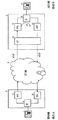
図11は、第4の実施形態のエコーキャンセラの詳細構成を、周囲の構成と共に示すブロック図であり、第3の実施形態に係る図9との同一、対応部分には同一符号を付して示している。
(D-1) Configuration of the Fourth Embodiment FIG. 11 is a block diagram showing the detailed configuration of the echo canceller of the fourth embodiment together with the surrounding configuration, and FIG. 9 is related to FIG. 9 according to the third embodiment. The same and corresponding parts are denoted by the same reference numerals.
図11において、第4の実施形態のエコーキャンセラ12Cは、第3の実施形態のトーン性判定器15B及び信号種別判定器16Bの構成部分を、信号成分判定器40に置き換えている点が第3の実施形態と異なっており、その他は、第3の実施形態と同様である。
In FIG. 11, the echo canceller 12C of the fourth embodiment has a third feature in that the component parts of the tone
信号成分判定器40は、受信入力端子Rinからの入力信号に基づき、信号KIND_TONE及びTENDを形成するものであり、その形成方法については、動作説明の項で明らかにする。
The signal
(D−2)第4の実施形態の動作
第4の実施形態が第3の実施形態と異なっているのは、信号成分判定器40の動作だけであるので、それについて説明し、他の部分についての説明は省略する。
(D-2) Operation of the fourth embodiment The fourth embodiment is different from the third embodiment only in the operation of the
信号成分判定器40は、入力信号が、既知の呼制御信号(例えばDT、DTMFなど)の種別かそれ以外かに拘わらず、入力信号が広帯域性の信号(入力信号の成分が広帯域に渡っている)か、そうでないかを判定するものである。信号成分判定器40は、例えば、呼制御信号ではない1500Hzなどのトーン信号などもトーン信号として判定するように動作する。
The signal
以下、信号成分判定器40における判定方法を説明する。
Hereinafter, a determination method in the signal
信号成分判定器40は、例えば、入力信号に高速離散フーリエ変換(FFT)を施し、個々の単一周波数成分に分解する。例えば、256点のFFTを用いて、入力信号を周波数成分に変換する。サンプリング周波数を16kHzとし、256点のFFTを用いると、入力信号の0〜8kHzの帯域に対し128個の分解能で各周波数成分を計算し、パワースペクトルP_f(k)を求めることができる。この第4の実施形態では、各パワースペクトルのうち、最も小さい周波数min_fのパワーP_min_fをノイズフロア周波数パワーレベルとみなし、下記の条件5を満たすとき、「周波数成分あり」とみなすようにした。
The signal
条件5: P_f(k)>P_min_f+δf
ここで、δfは、判定用オフセット値であり、15dBを適用できるが、この値に限定されるものではない。kは分解した周波数のうち何番目の周波数であるかを表しており、0≦k≦127の128個の値をとり得る。
Condition 5: P_f (k)> P_min_f + δf
Here, δf is a determination offset value, and 15 dB can be applied, but is not limited to this value. k represents the number of the decomposed frequencies, and can take 128 values of 0 ≦ k ≦ 127.
信号成分判定器40は、条件5を満足した周波数f(k)の個数を内蔵するカウンタでカウントし、そのカウント結果C_FがC_F<TH_VOICEであるとき、入力された信号が任意トーン性信号とみなして信号KIND_TONEをフィルタ状態判定器31に出力する。閾値パラメータTH_VOICEとして、例えば、4を適用できるが、これに限定されない。
The signal
この第4の実施形態ではトーン信号の種別を判定する必要がないので、第1〜第3の実施形態のように、信号KIND_TONEを形成するための情報を予め格納しておき、その情報を参照する必要がなく、信号KIND_TONEの出力の有無だけが問題である。 In the fourth embodiment, since it is not necessary to determine the type of the tone signal, information for forming the signal KIND_TONE is stored in advance as in the first to third embodiments, and the information is referred to. The only problem is whether or not the signal KIND_TONE is output.
なお、帯域阻止フィルタ21、22やフィルタ状態判定器31の構成との関係で、信号KIND_TONEに番号を付与する必要があるときには、例えば、上述した図8や図10で適用されていない番号を用いる。
In addition, when it is necessary to assign a number to the signal KIND_TONE in relation to the configurations of the band rejection filters 21 and 22 and the filter
第4の実施形態の場合、検出されるトーン信号の周波数が予め定まっていないので、帯域阻止フィルタ21、22には、周波数情報を盛り込んだ信号KIND_TONEを与えてフィルタ動作させれば良い。 In the case of the fourth embodiment, since the frequency of the detected tone signal is not determined in advance, the band rejection filters 21 and 22 may be subjected to a filter operation by applying a signal KIND_TONE incorporating frequency information.
信号成分判定器40は、トーン信号を上述したように条件5に従って検出している状態から検出し得なくなった状態に変化したときに、トーン信号の終了を表す信号TENDをフィルタ状態判定器31に出力する。
When the signal
(D−3)第4の実施形態の効果
第4の実施形態によれば、呼制御信号に分類されない任意のトーン信号(例えば、人間同士の通話における偶発的な人間のトーン性音声)に対する誤収束と、それに続くエコーキャンセラの誤動作を防止することができる。
(D-3) Effect of the Fourth Embodiment According to the fourth embodiment, an error occurs with respect to an arbitrary tone signal that is not classified as a call control signal (for example, an accidental human tone-like voice in a call between humans). Convergence and subsequent malfunction of the echo canceller can be prevented.
任意のトーン信号が入力される現象は、例えば、片方、あるいは両方の話者の背景音として話者音声と同じレベルで音楽がかかっている場合や、話者が通話中に歌唱を行う、話者個人の音声周波数特性が特異的にトーン性を持つ、などの場合に非常にまれではあるが発生する。そして、発生するトーン性の周波数は、呼制御トーンの周波数に限らず、任意であるので、既知の周波数表を参照することができない。第4の実施形態は、信号成分判定器40を設けて、たとえ周波数が任意であっても入力信号のトーン性を検出し、検出結果後は、第3の実施形態と同様に、適応フィルタとダブルトーク検出器を制御するようにしたので、適応フィルタの誤収束を防止し、エコー経路の初期遅延が小さくても誤収束の状態からすみやかに復帰し、ダブルトーク検出器も誤判定の状態から復帰でき、その結果、エコーを劣化することなく除去し続けることができるエコーキャンセラを実現できる。
An arbitrary tone signal is input when, for example, music is applied at the same level as the speaker's voice as the background sound of one or both speakers, or when the speaker sings during a call. It occurs very rarely when the individual person's voice frequency characteristics have specific tone characteristics. The generated tone frequency is not limited to the frequency of the call control tone, and is arbitrary, so a known frequency table cannot be referred to. In the fourth embodiment, a signal
(E)第5の実施形態
次に、本発明によるエコーキャンセラを、構内交換装置に設けられるエコーキャンセラに適用した第5の実施形態を、図面を参照しながら説明する。
(E) Fifth Embodiment Next, a fifth embodiment in which the echo canceller according to the present invention is applied to an echo canceller provided in a private branch exchange will be described with reference to the drawings.
第5の実施形態のエコーキャンセラは、第3や第4の実施形態より、ハード規模を小さくしようとしたものである。 The echo canceller of the fifth embodiment is intended to make the hardware scale smaller than those of the third and fourth embodiments.
(E−1)第5の実施形態の構成
図12は、第5の実施形態のエコーキャンセラの詳細構成を、周囲の構成と共に示すブロック図であり、第3の実施形態に係る図9との同一、対応部分には同一符号を付して示している。
(E-1) Configuration of Fifth Embodiment FIG. 12 is a block diagram showing the detailed configuration of the echo canceller of the fifth embodiment together with the surrounding configuration, and is a block diagram showing FIG. 9 according to the third embodiment. The same and corresponding parts are denoted by the same reference numerals.
図12において、第5の実施形態のエコーキャンセラ12Dは、第3の実施形態と比較すると、帯域阻止フィルタ21、22が設けられていないこと、信号種別判定器16Dの機能が第3の実施形態のものから多少変わっていることが異なっている。 In FIG. 12, the echo canceller 12D of the fifth embodiment is different from the third embodiment in that the band rejection filters 21 and 22 are not provided, and the function of the signal type determination unit 16D is the third embodiment. It is different that it is slightly different from the ones.
(E−2)第5の実施形態の動作
次に、第5の実施形態のエコーキャンセラ12Dの、第3の実施形態のものと異なっている動作を説明する。
(E-2) Operation of Fifth Embodiment Next, an operation of the echo canceller 12D of the fifth embodiment that is different from that of the third embodiment will be described.
着呼側電話機9−1、9−2の間に転送が発生するときの様子を説明する。転送が発生する前後の説明であるので、図示しない発呼側電話機と着呼側電話機9−1とは、既に通話している状態であるとして説明をする。 A situation when a transfer occurs between the receiving side telephones 9-1 and 9-2 will be described. Since the description is before and after the transfer is generated, the calling side telephone and the called side telephone 9-1 (not shown) will be described as being already in a call state.
信号種別判定器16Dは、トーン性判定器15Bの出力がトーン性あり信号TONからトーン性なし信号TOFFになったとき、フィルタ状態判定器31にトーン信号の終了を表す信号TENDを出力する。
The signal type determiner 16D outputs a signal TEND indicating the end of the tone signal to the
フィルタ状態判定器31は、信号種別判定器16Dからの出力TENDがあったときには、第3の実施形態と同様に上述した条件1〜条件4の判定を行い、判定結果に応じて、係数制御器17Bに係数制御用の信号ADP_F、ADP_STP又はADP_RSTを出力し、適応フィルタ18の係数更新を制御する。このような制御時以外では、適応フィルタ18はダブルトーク検出器14Bの係数更新制御に従う。
When there is an output TEND from the signal type determiner 16D, the
以下、転送時の動作について説明するが、既述した実施形態と異なり、この第5の実施形態では、ハイブリッド回路の応答特性の変動、及び、適応フィルタの収束状態の良否を細かく分ける必要がないので、まとめて説明する。 Hereinafter, the operation at the time of transfer will be described. However, unlike the above-described embodiment, in the fifth embodiment, it is not necessary to finely divide the fluctuation of the response characteristic of the hybrid circuit and the convergence state of the adaptive filter. So, I will explain it together.
転送前に多少の通話が行われ、音声によって適応フィルタ18は収束の途中である。このとき、図示しない遠端話者は、DTMF信号を入力するなどして異なる電話機に対する接続を要求する。
Some calls are made before transfer, and the
受信入力端子Rinに入力されたDTMF信号は、トーン性判定器15Bに入力されると共に、受信出力端子Routをそのまま通過して、D/A変換器7に入力される。
The DTMF signal input to the reception input terminal Rin is input to the
このとき、トーン性判定器15Bは、入力信号についてトーン性を検出するが、信号種別判定器16Dは、この時点では何も出力しない。従って、フィルタ状態判定器31もなにもせず、適応フィルタ18は係数更新を継続し、トーン由来のエコーを除去する。このとき、適応フィルタ18の係数は、上述したように、エコー経路の特性とは異なるが、トーンは良く消せるような係数に更新されていく。従って、加算器13の出力は小さくなり、ERLEは大きい値を持つようになる。
At this time, the
次に、トーン信号が終了すると、信号種別判定器16Dは、フィルタ状態判定器31にトーン終了信号TENDを出力する。
Next, when the tone signal ends, the signal type determiner 16D outputs the tone end signal TEND to the
この信号TENDを受けたフィルタ状態判定器31は、前回保持したエコー消去量ACANC(n)と新たにエコー消去量計算器32から出力されたエコー消去量ACANC(n+1)を比較する。本ケースの場合、ハイブリッド回路8−1の特性がハイブリッド回路8−2の特性と同様であるとすると、トーン終了信号TENDの前後の収束状態に拘わらず、信号TENDが入力される時点では、適応フィルタ18の係数はトーン信号だけを除去するのに都合良く擾乱をうけており、その後の通常音声信号でのエコー消去量によって、条件2、条件3若しくは条件4が成立する。このとき、条件3若しくは条件4に基づき、第3の実施形態のように、ダブルトーク検出器14Bと適応フィルタ18の再更新が実行される。
Receiving this signal TEND, the filter
また、条件1が成立するのは、信号TENDの入力タイミング前後で、DTMF信号によって係数が擾乱をさほど受けなかったということであり、その後の音声信号でも十分にエコーを除去できる場合であるから、事前の適応フィルタ18の収束が十分で、ハイブリッド回路の特性が変化しない内線転送ケースCのみで起こる。このとき、適応フィルタ18は、そのまま係数の更新を進行するのが望ましく、係数制御器17Bはなにも出力しなので、適応フィルタ18、ダブルトーク検出器14Bは所望のとおり、通常のエコー除去動作を進行し、トーン信号発生前後でエコーの劣化なくエコー除去を進行できる。
Further, the
(E−3)第5の実施形態の効果
第5の実施形態によれば、トーン信号の擾乱を未然に防止することはできないが、転送発生時にほとんどの場合に適応フィルタ係数をリセットするようにし、ダブルトーク検出器をリセットして再開の係数更新を阻害しないようにし、エコー経路の初期遅延の大小に拘わらず、再収束が可能なので、一瞬エコーの発生を伴うが、誤収束の状態から直ちに復帰して再収束を開始し、予め複数の帯域阻止フィルタを準備する必要がない分、ハード規模を小さいエコーキャンセラを提供できる。
(E-3) Effect of Fifth Embodiment According to the fifth embodiment, the disturbance of the tone signal cannot be prevented in advance, but the adaptive filter coefficient is reset in most cases when a transfer occurs. The double-talk detector is reset so as not to hinder the renewal coefficient update, and re-convergence is possible regardless of the initial delay of the echo path. It is possible to provide an echo canceller with a small hardware scale because there is no need to prepare a plurality of band rejection filters in advance by returning and starting reconvergence.
(F)他の実施形態
上記各実施形態の技術思想のうち、組み合わせが可能なものを組み合わせてエコーキャンセラを構成するようにしても良い。
(F) Other Embodiments The echo canceller may be configured by combining those that can be combined among the technical ideas of the above embodiments.
上記第3、第4の実施形態では、エコー消去量を計算するのに加算器前後の入力の自乗比を計算するエコー消去量計算器を用いたが、加算器の出力信号と受信入力端子Rinの出力信号、又は、加算器の出力信号と受信出力端子Routの入力信号を用いるようにしても良い。この場合、第3、第4の実施形態で説明したΔ1、Δ2にエコー経路自体がもつ減衰量を加えるなどすれば良い。 In the third and fourth embodiments, the echo cancellation amount calculator that calculates the square ratio of the input before and after the adder is used to calculate the echo cancellation amount. However, the output signal of the adder and the reception input terminal Rin are used. Or the output signal of the adder and the input signal of the reception output terminal Rout may be used. In this case, the attenuation amount of the echo path itself may be added to Δ1 and Δ2 described in the third and fourth embodiments.
また、第4の実施形態において、信号成分判定器40において、任意トーン周波数を検出するためにFFTを利用する方法を用いたが、任意単一トーンを検出できる方法であればFFT以外の方法を使っても良く、FFTを利用する方法に限定されない。
In the fourth embodiment, the signal
さらに、第2〜第4の実施形態においては、2個の帯域阻止フィルタを有するものを示したが、少なくとも、適応フィルタの入力段に、帯域阻止フィルタを備えるようにしても良い。 Furthermore, in the second to fourth embodiments, the one having two band rejection filters has been shown, but at least the band rejection filter may be provided in the input stage of the adaptive filter.
さらにまた、上記各実施形態の説明では、各構成要素がハードウェアで構成されているイメージで説明したが、一部の構成要素をソフトウェアによって実現しても良いことは勿論である。 Furthermore, in the description of each of the above embodiments, each component has been described as an image configured with hardware, but it is needless to say that some components may be realized by software.
第1及び第2の実施形態では、エコーキャンセラがVoIP端末に搭載され、第3〜第5の実施形態では、エコーキャンセラが構内交換装置に搭載された用途例を示したが、本発明のエコーキャンセラが搭載される装置はこれらに限定されないことは勿論である。 In the first and second embodiments, the echo canceller is mounted on the VoIP terminal, and in the third to fifth embodiments, the application example in which the echo canceller is mounted on the private branch exchange is shown. Of course, the apparatus on which the canceller is mounted is not limited to these.
12、12A、12B、12C、12D…エコーキャンセラ、13…加算器、14、14B…ダブルトーク検出器、15、15B…トーン性判定器、16、16A、16B、16D…信号種別判定器、17、17B…係数制御器、18…適応フィルタ、21、22…帯域阻止フィルタ、31…フィルタ状態判定器、32…エコー消去量計算器、40…信号成分判定器。 12, 12A, 12B, 12C, 12D ... echo canceller, 13 ... adder, 14, 14B ... double talk detector, 15, 15B ... tone property determiner, 16, 16A, 16B, 16D ... signal type determiner, 17 , 17B ... coefficient controller, 18 ... adaptive filter, 21, 22 ... band rejection filter, 31 ... filter state determiner, 32 ... echo cancellation amount calculator, 40 ... signal component determiner.
Claims (3)
遠端入力信号が所定種別のトーン信号であるか否かを判定するトーン種別判定手段と、
上記トーン種別判定手段が、遠端入力信号が所定種別のトーン信号であると判定したときに、上記適応フィルタへの遠端入力信号から、判定された所定種別のトーン信号の周波数成分を除去する、上記適応フィルタの入力段に設けられた第1の帯域阻止フィルタと
を有することを特徴とするエコーキャンセラ。 In an echo canceller that uses an adaptive filter to generate pseudo echoes and removes echoes caused by hybrid circuits,
Tone type determination means for determining whether the far-end input signal is a predetermined type of tone signal;
When the tone type determining means determines that the far-end input signal is a predetermined type of tone signal, the frequency component of the determined predetermined-type tone signal is removed from the far-end input signal to the adaptive filter. An echo canceller comprising: a first band rejection filter provided at an input stage of the adaptive filter.
上記ダブルトーク検出手段には、上記第1の帯域阻止フィルタを通過した近端入力信号を入力する
ことを特徴とする請求項1に記載のエコーキャンセラ。 A double-talk detecting means for detecting a double-talk state of the far-end speaker and the near-end speaker;
The echo canceller according to claim 1, wherein the double-talk detection unit receives a near-end input signal that has passed through the first band rejection filter.
上記トーン種別判定手段が、遠端入力信号が所定種別のトーン信号であると判定したときに、上記加算手段への近端入力信号から、判定された所定種別のトーン信号の周波数成分を除去する、上記加算手段の入力段に設けられた第2の帯域阻止フィルタを有する
ことを特徴とする請求項1又は2に記載のエコーキャンセラ。 Adding means for subtracting the pseudo echo signal from the adaptive filter from the near-end input signal;
When the tone type determining means determines that the far-end input signal is a predetermined type of tone signal, the frequency component of the determined predetermined type of tone signal is removed from the near-end input signal to the adding means. The echo canceller according to claim 1, further comprising a second band rejection filter provided at an input stage of the adding means.
Priority Applications (1)
| Application Number | Priority Date | Filing Date | Title |
|---|---|---|---|
| JP2010192208A JP2011055494A (en) | 2010-08-30 | 2010-08-30 | Echo canceller |
Applications Claiming Priority (1)
| Application Number | Priority Date | Filing Date | Title |
|---|---|---|---|
| JP2010192208A JP2011055494A (en) | 2010-08-30 | 2010-08-30 | Echo canceller |
Related Parent Applications (1)
| Application Number | Title | Priority Date | Filing Date |
|---|---|---|---|
| JP2005370171A Division JP4752494B2 (en) | 2005-12-22 | 2005-12-22 | Echo canceller |
Publications (1)
| Publication Number | Publication Date |
|---|---|
| JP2011055494A true JP2011055494A (en) | 2011-03-17 |
Family
ID=43943975
Family Applications (1)
| Application Number | Title | Priority Date | Filing Date |
|---|---|---|---|
| JP2010192208A Pending JP2011055494A (en) | 2010-08-30 | 2010-08-30 | Echo canceller |
Country Status (1)
| Country | Link |
|---|---|
| JP (1) | JP2011055494A (en) |
Cited By (8)
| Publication number | Priority date | Publication date | Assignee | Title |
|---|---|---|---|---|
| JP2015525490A (en) * | 2012-05-10 | 2015-09-03 | シラス ロジック、インコーポレイテッド | Adaptation of secondary path response model in downlink tone detection and noise cancellation system |
| US9711130B2 (en) | 2011-06-03 | 2017-07-18 | Cirrus Logic, Inc. | Adaptive noise canceling architecture for a personal audio device |
| US9773493B1 (en) | 2012-09-14 | 2017-09-26 | Cirrus Logic, Inc. | Power management of adaptive noise cancellation (ANC) in a personal audio device |
| US9773490B2 (en) | 2012-05-10 | 2017-09-26 | Cirrus Logic, Inc. | Source audio acoustic leakage detection and management in an adaptive noise canceling system |
| US9824677B2 (en) | 2011-06-03 | 2017-11-21 | Cirrus Logic, Inc. | Bandlimiting anti-noise in personal audio devices having adaptive noise cancellation (ANC) |
| US9955250B2 (en) | 2013-03-14 | 2018-04-24 | Cirrus Logic, Inc. | Low-latency multi-driver adaptive noise canceling (ANC) system for a personal audio device |
| US10026388B2 (en) | 2015-08-20 | 2018-07-17 | Cirrus Logic, Inc. | Feedback adaptive noise cancellation (ANC) controller and method having a feedback response partially provided by a fixed-response filter |
| US10468048B2 (en) | 2011-06-03 | 2019-11-05 | Cirrus Logic, Inc. | Mic covering detection in personal audio devices |
Citations (3)
| Publication number | Priority date | Publication date | Assignee | Title |
|---|---|---|---|---|
| JPH11308357A (en) * | 1998-04-24 | 1999-11-05 | Mitsubishi Electric Corp | Data communication device |
| JP2002280938A (en) * | 2001-03-21 | 2002-09-27 | Oki Electric Ind Co Ltd | Echo canceller |
| JP2005217547A (en) * | 2004-01-27 | 2005-08-11 | Matsushita Electric Works Ltd | Amplified sound speech device |
-
2010
- 2010-08-30 JP JP2010192208A patent/JP2011055494A/en active Pending
Patent Citations (3)
| Publication number | Priority date | Publication date | Assignee | Title |
|---|---|---|---|---|
| JPH11308357A (en) * | 1998-04-24 | 1999-11-05 | Mitsubishi Electric Corp | Data communication device |
| JP2002280938A (en) * | 2001-03-21 | 2002-09-27 | Oki Electric Ind Co Ltd | Echo canceller |
| JP2005217547A (en) * | 2004-01-27 | 2005-08-11 | Matsushita Electric Works Ltd | Amplified sound speech device |
Cited By (10)
| Publication number | Priority date | Publication date | Assignee | Title |
|---|---|---|---|---|
| US9711130B2 (en) | 2011-06-03 | 2017-07-18 | Cirrus Logic, Inc. | Adaptive noise canceling architecture for a personal audio device |
| US9824677B2 (en) | 2011-06-03 | 2017-11-21 | Cirrus Logic, Inc. | Bandlimiting anti-noise in personal audio devices having adaptive noise cancellation (ANC) |
| US10249284B2 (en) | 2011-06-03 | 2019-04-02 | Cirrus Logic, Inc. | Bandlimiting anti-noise in personal audio devices having adaptive noise cancellation (ANC) |
| US10468048B2 (en) | 2011-06-03 | 2019-11-05 | Cirrus Logic, Inc. | Mic covering detection in personal audio devices |
| JP2015525490A (en) * | 2012-05-10 | 2015-09-03 | シラス ロジック、インコーポレイテッド | Adaptation of secondary path response model in downlink tone detection and noise cancellation system |
| US9721556B2 (en) | 2012-05-10 | 2017-08-01 | Cirrus Logic, Inc. | Downlink tone detection and adaptation of a secondary path response model in an adaptive noise canceling system |
| US9773490B2 (en) | 2012-05-10 | 2017-09-26 | Cirrus Logic, Inc. | Source audio acoustic leakage detection and management in an adaptive noise canceling system |
| US9773493B1 (en) | 2012-09-14 | 2017-09-26 | Cirrus Logic, Inc. | Power management of adaptive noise cancellation (ANC) in a personal audio device |
| US9955250B2 (en) | 2013-03-14 | 2018-04-24 | Cirrus Logic, Inc. | Low-latency multi-driver adaptive noise canceling (ANC) system for a personal audio device |
| US10026388B2 (en) | 2015-08-20 | 2018-07-17 | Cirrus Logic, Inc. | Feedback adaptive noise cancellation (ANC) controller and method having a feedback response partially provided by a fixed-response filter |
Similar Documents
| Publication | Publication Date | Title |
|---|---|---|
| JP4752494B2 (en) | Echo canceller | |
| RU2150174C1 (en) | System and method for preventing false convergence in presence of call tone signal at echo signal pressure in time domain | |
| JP2011055494A (en) | Echo canceller | |
| US8098812B2 (en) | Method of controlling an adaptation of a filter | |
| US7203308B2 (en) | Echo canceller ensuring further reduction in residual echo | |
| EP1786191B1 (en) | Acoustic echo canceller | |
| JP4457639B2 (en) | Echo canceller | |
| JPH06204916A (en) | Remaining echo controller | |
| US8041027B2 (en) | Electricity echo cancellation device and method | |
| WO2004015961A2 (en) | Estimating bulk delay in a telephone system | |
| JP2944310B2 (en) | Echo canceller | |
| EP0929174B1 (en) | Voice switching system capable of improving a quality of conversation | |
| KR20130038332A (en) | Echo canceller | |
| JP2010016478A (en) | Voice communication apparatus | |
| JPH0766756A (en) | Acoustic echo canceler | |
| JP2002280938A (en) | Echo canceller | |
| US20040120511A1 (en) | Method of capturing constant echo path information in a full duplex speakerphone | |
| JP4475155B2 (en) | Echo canceller | |
| JP4576847B2 (en) | Echo canceller control device and voice communication device | |
| US7734036B1 (en) | Dynamic attenuation method and apparatus for optimizing voice quality using echo cancellers | |
| JP3862548B2 (en) | Echo canceller | |
| JP5293342B2 (en) | Voice communication apparatus, method and program | |
| EP2223522B1 (en) | Non linear acoustic feedback suppression in a telephone device | |
| GB2410661A (en) | Narrow band tone detection in echo cancelling system | |
| JP5350968B2 (en) | Automatic line disconnect device |
Legal Events
| Date | Code | Title | Description |
|---|---|---|---|
| A131 | Notification of reasons for refusal |
Free format text: JAPANESE INTERMEDIATE CODE: A131 Effective date: 20120221 |
|
| A02 | Decision of refusal |
Free format text: JAPANESE INTERMEDIATE CODE: A02 Effective date: 20120619 |