JP2011037521A - Method for manufacturing composite hook/loop fastening tool - Google Patents
Method for manufacturing composite hook/loop fastening tool Download PDFInfo
- Publication number
- JP2011037521A JP2011037521A JP2010246350A JP2010246350A JP2011037521A JP 2011037521 A JP2011037521 A JP 2011037521A JP 2010246350 A JP2010246350 A JP 2010246350A JP 2010246350 A JP2010246350 A JP 2010246350A JP 2011037521 A JP2011037521 A JP 2011037521A
- Authority
- JP
- Japan
- Prior art keywords
- loop
- hook
- component
- fastener
- wrap tie
- Prior art date
- Legal status (The legal status is an assumption and is not a legal conclusion. Google has not performed a legal analysis and makes no representation as to the accuracy of the status listed.)
- Pending
Links
- 239000002131 composite material Substances 0.000 title claims abstract description 32
- 238000000034 method Methods 0.000 title claims abstract description 32
- 238000004519 manufacturing process Methods 0.000 title claims abstract description 15
- 239000000463 material Substances 0.000 claims abstract description 193
- 239000000835 fiber Substances 0.000 claims abstract description 56
- 238000005520 cutting process Methods 0.000 claims abstract description 12
- 239000004033 plastic Substances 0.000 claims abstract description 9
- 229920003023 plastic Polymers 0.000 claims abstract description 9
- 229920005989 resin Polymers 0.000 claims description 41
- 239000011347 resin Substances 0.000 claims description 41
- 239000010410 layer Substances 0.000 claims description 37
- 239000004820 Pressure-sensitive adhesive Substances 0.000 claims description 25
- 229920003002 synthetic resin Polymers 0.000 claims description 24
- 239000000057 synthetic resin Substances 0.000 claims description 24
- 239000000758 substrate Substances 0.000 claims description 13
- 239000012790 adhesive layer Substances 0.000 claims description 10
- 238000003466 welding Methods 0.000 claims description 10
- 239000000853 adhesive Substances 0.000 claims description 8
- 230000001070 adhesive effect Effects 0.000 claims description 8
- 238000004806 packaging method and process Methods 0.000 claims description 7
- 239000011230 binding agent Substances 0.000 claims description 5
- 238000005304 joining Methods 0.000 claims description 3
- 230000008878 coupling Effects 0.000 claims description 2
- 238000010168 coupling process Methods 0.000 claims description 2
- 238000005859 coupling reaction Methods 0.000 claims description 2
- 238000001125 extrusion Methods 0.000 claims description 2
- 235000001674 Agaricus brunnescens Nutrition 0.000 claims 1
- 239000011248 coating agent Substances 0.000 claims 1
- 238000000576 coating method Methods 0.000 claims 1
- 239000004615 ingredient Substances 0.000 claims 1
- 238000000926 separation method Methods 0.000 claims 1
- 239000011800 void material Substances 0.000 claims 1
- 238000000465 moulding Methods 0.000 abstract description 5
- 239000004744 fabric Substances 0.000 description 15
- 229920000728 polyester Polymers 0.000 description 5
- 238000010586 diagram Methods 0.000 description 4
- 239000004698 Polyethylene Substances 0.000 description 3
- 239000000155 melt Substances 0.000 description 3
- -1 polyethylene Polymers 0.000 description 3
- 229920000573 polyethylene Polymers 0.000 description 3
- OKTJSMMVPCPJKN-UHFFFAOYSA-N Carbon Chemical compound [C] OKTJSMMVPCPJKN-UHFFFAOYSA-N 0.000 description 2
- 229910000975 Carbon steel Inorganic materials 0.000 description 2
- 239000010962 carbon steel Substances 0.000 description 2
- 230000004927 fusion Effects 0.000 description 2
- 239000007788 liquid Substances 0.000 description 2
- 238000002844 melting Methods 0.000 description 2
- 230000008569 process Effects 0.000 description 2
- 239000010935 stainless steel Substances 0.000 description 2
- 229910001220 stainless steel Inorganic materials 0.000 description 2
- XUIMIQQOPSSXEZ-UHFFFAOYSA-N Silicon Chemical compound [Si] XUIMIQQOPSSXEZ-UHFFFAOYSA-N 0.000 description 1
- 208000027418 Wounds and injury Diseases 0.000 description 1
- 229920005822 acrylic binder Polymers 0.000 description 1
- 238000004026 adhesive bonding Methods 0.000 description 1
- 238000005054 agglomeration Methods 0.000 description 1
- 230000002776 aggregation Effects 0.000 description 1
- 238000013459 approach Methods 0.000 description 1
- 230000015572 biosynthetic process Effects 0.000 description 1
- 235000012180 bread and bread product Nutrition 0.000 description 1
- 239000004566 building material Substances 0.000 description 1
- 230000006378 damage Effects 0.000 description 1
- 230000005611 electricity Effects 0.000 description 1
- 239000003000 extruded plastic Substances 0.000 description 1
- 238000011065 in-situ storage Methods 0.000 description 1
- 208000014674 injury Diseases 0.000 description 1
- 238000002372 labelling Methods 0.000 description 1
- 230000008018 melting Effects 0.000 description 1
- 239000002184 metal Substances 0.000 description 1
- 239000004745 nonwoven fabric Substances 0.000 description 1
- 229910052710 silicon Inorganic materials 0.000 description 1
- 239000010703 silicon Substances 0.000 description 1
- 230000003068 static effect Effects 0.000 description 1
- 230000032258 transport Effects 0.000 description 1
- 238000004804 winding Methods 0.000 description 1
Images


Classifications
-
- A—HUMAN NECESSITIES
- A44—HABERDASHERY; JEWELLERY
- A44B—BUTTONS, PINS, BUCKLES, SLIDE FASTENERS, OR THE LIKE
- A44B18/00—Fasteners of the touch-and-close type; Making such fasteners
- A44B18/0046—Fasteners made integrally of plastics
- A44B18/0049—Fasteners made integrally of plastics obtained by moulding processes
-
- A—HUMAN NECESSITIES
- A44—HABERDASHERY; JEWELLERY
- A44B—BUTTONS, PINS, BUCKLES, SLIDE FASTENERS, OR THE LIKE
- A44B18/00—Fasteners of the touch-and-close type; Making such fasteners
- A44B18/0069—Details
- A44B18/008—Hooks or loops provided with means to reinforce the attachment, e.g. by adhesive means
-
- A—HUMAN NECESSITIES
- A44—HABERDASHERY; JEWELLERY
- A44B—BUTTONS, PINS, BUCKLES, SLIDE FASTENERS, OR THE LIKE
- A44B18/00—Fasteners of the touch-and-close type; Making such fasteners
- A44B18/0069—Details
- A44B18/0088—Mixed male and female members
-
- B—PERFORMING OPERATIONS; TRANSPORTING
- B29—WORKING OF PLASTICS; WORKING OF SUBSTANCES IN A PLASTIC STATE IN GENERAL
- B29C—SHAPING OR JOINING OF PLASTICS; SHAPING OF MATERIAL IN A PLASTIC STATE, NOT OTHERWISE PROVIDED FOR; AFTER-TREATMENT OF THE SHAPED PRODUCTS, e.g. REPAIRING
- B29C43/00—Compression moulding, i.e. applying external pressure to flow the moulding material; Apparatus therefor
- B29C43/32—Component parts, details or accessories; Auxiliary operations
- B29C43/44—Compression means for making articles of indefinite length
- B29C43/46—Rollers
- B29C2043/461—Rollers the rollers having specific surface features
- B29C2043/465—Rollers the rollers having specific surface features having one or more cavities, e.g. for forming distinct products
-
- B—PERFORMING OPERATIONS; TRANSPORTING
- B29—WORKING OF PLASTICS; WORKING OF SUBSTANCES IN A PLASTIC STATE IN GENERAL
- B29L—INDEXING SCHEME ASSOCIATED WITH SUBCLASS B29C, RELATING TO PARTICULAR ARTICLES
- B29L2031/00—Other particular articles
- B29L2031/727—Fastening elements
- B29L2031/729—Hook and loop-type fasteners
-
- Y—GENERAL TAGGING OF NEW TECHNOLOGICAL DEVELOPMENTS; GENERAL TAGGING OF CROSS-SECTIONAL TECHNOLOGIES SPANNING OVER SEVERAL SECTIONS OF THE IPC; TECHNICAL SUBJECTS COVERED BY FORMER USPC CROSS-REFERENCE ART COLLECTIONS [XRACs] AND DIGESTS
- Y10—TECHNICAL SUBJECTS COVERED BY FORMER USPC
- Y10T—TECHNICAL SUBJECTS COVERED BY FORMER US CLASSIFICATION
- Y10T24/00—Buckles, buttons, clasps, etc.
- Y10T24/15—Bag fasteners
-
- Y—GENERAL TAGGING OF NEW TECHNOLOGICAL DEVELOPMENTS; GENERAL TAGGING OF CROSS-SECTIONAL TECHNOLOGIES SPANNING OVER SEVERAL SECTIONS OF THE IPC; TECHNICAL SUBJECTS COVERED BY FORMER USPC CROSS-REFERENCE ART COLLECTIONS [XRACs] AND DIGESTS
- Y10—TECHNICAL SUBJECTS COVERED BY FORMER USPC
- Y10T—TECHNICAL SUBJECTS COVERED BY FORMER US CLASSIFICATION
- Y10T24/00—Buckles, buttons, clasps, etc.
- Y10T24/27—Buckles, buttons, clasps, etc. including readily dissociable fastener having numerous, protruding, unitary filaments randomly interlocking with, and simultaneously moving towards, mating structure [e.g., hook-loop type fastener]
- Y10T24/2708—Combined with diverse fastener
-
- Y—GENERAL TAGGING OF NEW TECHNOLOGICAL DEVELOPMENTS; GENERAL TAGGING OF CROSS-SECTIONAL TECHNOLOGIES SPANNING OVER SEVERAL SECTIONS OF THE IPC; TECHNICAL SUBJECTS COVERED BY FORMER USPC CROSS-REFERENCE ART COLLECTIONS [XRACs] AND DIGESTS
- Y10—TECHNICAL SUBJECTS COVERED BY FORMER USPC
- Y10T—TECHNICAL SUBJECTS COVERED BY FORMER US CLASSIFICATION
- Y10T24/00—Buckles, buttons, clasps, etc.
- Y10T24/27—Buckles, buttons, clasps, etc. including readily dissociable fastener having numerous, protruding, unitary filaments randomly interlocking with, and simultaneously moving towards, mating structure [e.g., hook-loop type fastener]
- Y10T24/2742—Buckles, buttons, clasps, etc. including readily dissociable fastener having numerous, protruding, unitary filaments randomly interlocking with, and simultaneously moving towards, mating structure [e.g., hook-loop type fastener] having filaments of varied shape or size on same mounting surface
-
- Y—GENERAL TAGGING OF NEW TECHNOLOGICAL DEVELOPMENTS; GENERAL TAGGING OF CROSS-SECTIONAL TECHNOLOGIES SPANNING OVER SEVERAL SECTIONS OF THE IPC; TECHNICAL SUBJECTS COVERED BY FORMER USPC CROSS-REFERENCE ART COLLECTIONS [XRACs] AND DIGESTS
- Y10—TECHNICAL SUBJECTS COVERED BY FORMER USPC
- Y10T—TECHNICAL SUBJECTS COVERED BY FORMER US CLASSIFICATION
- Y10T24/00—Buckles, buttons, clasps, etc.
- Y10T24/27—Buckles, buttons, clasps, etc. including readily dissociable fastener having numerous, protruding, unitary filaments randomly interlocking with, and simultaneously moving towards, mating structure [e.g., hook-loop type fastener]
- Y10T24/275—Buckles, buttons, clasps, etc. including readily dissociable fastener having numerous, protruding, unitary filaments randomly interlocking with, and simultaneously moving towards, mating structure [e.g., hook-loop type fastener] with feature facilitating or causing attachment of filaments to mounting surface
- Y10T24/2758—Thermal or adhesive
-
- Y—GENERAL TAGGING OF NEW TECHNOLOGICAL DEVELOPMENTS; GENERAL TAGGING OF CROSS-SECTIONAL TECHNOLOGIES SPANNING OVER SEVERAL SECTIONS OF THE IPC; TECHNICAL SUBJECTS COVERED BY FORMER USPC CROSS-REFERENCE ART COLLECTIONS [XRACs] AND DIGESTS
- Y10—TECHNICAL SUBJECTS COVERED BY FORMER USPC
- Y10T—TECHNICAL SUBJECTS COVERED BY FORMER US CLASSIFICATION
- Y10T24/00—Buckles, buttons, clasps, etc.
- Y10T24/27—Buckles, buttons, clasps, etc. including readily dissociable fastener having numerous, protruding, unitary filaments randomly interlocking with, and simultaneously moving towards, mating structure [e.g., hook-loop type fastener]
- Y10T24/2775—Buckles, buttons, clasps, etc. including readily dissociable fastener having numerous, protruding, unitary filaments randomly interlocking with, and simultaneously moving towards, mating structure [e.g., hook-loop type fastener] having opposed structure formed from distinct filaments of diverse shape to those mating therewith
-
- Y—GENERAL TAGGING OF NEW TECHNOLOGICAL DEVELOPMENTS; GENERAL TAGGING OF CROSS-SECTIONAL TECHNOLOGIES SPANNING OVER SEVERAL SECTIONS OF THE IPC; TECHNICAL SUBJECTS COVERED BY FORMER USPC CROSS-REFERENCE ART COLLECTIONS [XRACs] AND DIGESTS
- Y10—TECHNICAL SUBJECTS COVERED BY FORMER USPC
- Y10T—TECHNICAL SUBJECTS COVERED BY FORMER US CLASSIFICATION
- Y10T24/00—Buckles, buttons, clasps, etc.
- Y10T24/27—Buckles, buttons, clasps, etc. including readily dissociable fastener having numerous, protruding, unitary filaments randomly interlocking with, and simultaneously moving towards, mating structure [e.g., hook-loop type fastener]
- Y10T24/2792—Buckles, buttons, clasps, etc. including readily dissociable fastener having numerous, protruding, unitary filaments randomly interlocking with, and simultaneously moving towards, mating structure [e.g., hook-loop type fastener] having mounting surface and filaments constructed from common piece of material
-
- Y—GENERAL TAGGING OF NEW TECHNOLOGICAL DEVELOPMENTS; GENERAL TAGGING OF CROSS-SECTIONAL TECHNOLOGIES SPANNING OVER SEVERAL SECTIONS OF THE IPC; TECHNICAL SUBJECTS COVERED BY FORMER USPC CROSS-REFERENCE ART COLLECTIONS [XRACs] AND DIGESTS
- Y10—TECHNICAL SUBJECTS COVERED BY FORMER USPC
- Y10T—TECHNICAL SUBJECTS COVERED BY FORMER US CLASSIFICATION
- Y10T24/00—Buckles, buttons, clasps, etc.
- Y10T24/33—Buckles, buttons, clasps, etc. having adhesive fastener
Landscapes
- Engineering & Computer Science (AREA)
- Mechanical Engineering (AREA)
- Slide Fasteners, Snap Fasteners, And Hook Fasteners (AREA)
- Bag Frames (AREA)
- Package Frames And Binding Bands (AREA)
- Packages (AREA)
- Nonwoven Fabrics (AREA)
- Laminated Bodies (AREA)
Abstract
Description
本発明は、フック/ループ固締具、その製造方法、およびそれを含む製品に関する。 The present invention relates to a hook / loop fastener, a method for manufacturing the same, and a product including the same.
代表的な複合フック/ループ固締具は、予備成形フックおよびループ材料を用意し、これら2種類の材料をそれぞれの縁部余白部に沿って一緒に重ねて付着させるか、または一方の材料を他方の材料の上に全体的に重ねて製造する。付着は、超音波溶接、熱溶融、または接着剤結合により一般に行われる。予備成形フックおよびループ材料を付着させて複合固締具を形成するこのステップは、製造工程に余計なコストを追加することになる。フックおよびループ材料は、フック構成要素の形成時に現場で積層しても良い。 A typical composite hook / loop fastener provides a preformed hook and loop material and either the two materials are stacked together along their respective edge margins, or one of the materials is attached. Produced overlaid entirely on the other material. Adhesion is generally performed by ultrasonic welding, heat melting, or adhesive bonding. This step of attaching the preformed hook and loop material to form a composite fastener adds extra cost to the manufacturing process. The hook and loop material may be laminated in situ during the formation of the hook component.
以下に詳細に説明する改良複合固締具の1つの特定用途は、袋を閉鎖するための包装結合具としての用途である。小売店で一般に使用される経済的な袋結合具は、紙で被覆されたワイヤを含む。このワイヤ結合具は、袋の開放端部周囲に巻かれ、ワイヤの両端が一緒に捻られて袋を閉鎖する。袋結合具のもう1つの一般的なタイプは、開口部を備えるプラスチックの断片から成るクリップ結合具である。袋のまとめられた開放端部は、開口部の側に押し込まれて袋を閉鎖する。その他の閉鎖具としては、紐およびテープ、並びに接着剤または剥離可能に係合可能な要素を使用する閉鎖装置が挙げられる。 One particular application of the improved composite fastener described in detail below is as a wrap tie for closing a bag. Economic bag ties commonly used in retail stores include paper-coated wires. The wire coupler is wrapped around the open end of the bag and both ends of the wire are twisted together to close the bag. Another common type of bag coupler is a clip coupler consisting of a piece of plastic with an opening. The gathered open end of the bag is pushed to the side of the opening to close the bag. Other closures include laces and tapes, and closure devices that use adhesives or releasably engageable elements.
ワイヤ結合具およびクリップ結合具は、パン製品、生鮮飲食品、乾燥品、釘などのような物品を袋の中に入れて、重量または数で販売する小売店舗で使用されることが多い。消費者は、通常、これら商品を袋に入れて保管する。結合具は、袋が空になるまで数回にわたって開閉される場合がある。こうした用途およびその他の多くの用途のために、低価格で信頼でき、繰り返し使用される閉鎖具に対する必要性がある。 Wire couplers and clip couplers are often used in retail stores where items such as bread products, perishables, dried products, nails, etc. are placed in bags and sold by weight or number. Consumers usually store these items in bags. The coupler may be opened and closed several times until the bag is empty. For these and many other applications, there is a need for a low cost, reliable and reusable closure.
長形ストリップの形態の複合フック/ループ固締具は、ループ構成要素と、ループ構成要素に永久的に取り付けられるフック構成要素と、個々の領域における包装結合具の表面に配置される基材層とを含む。基材層は、包装結合具を支持面に永久的に取り付けるために使用される。ループ構成要素の一方の端部は、包装される物体を囲み、フック構成要素の固締具要素に係合するために使用される。ループ構成要素は、繊維が絡み合った自己支持ウェブを有し、この繊維は、シート状本体と、この本体の少なくとも1つの表面から延在するフック係合可能な自立ループとを形成し、フック構成要素は、共通の基部から延在する固締具要素を有する。 A composite hook / loop fastener in the form of an elongated strip comprises a loop component, a hook component permanently attached to the loop component, and a substrate layer disposed on the surface of the wrap tie in individual areas Including. The substrate layer is used to permanently attach the wrap tie to the support surface. One end of the loop component surrounds the object to be packaged and is used to engage the fastener component of the hook component. The loop component has a self-supporting web intertwined with fibers, the fibers forming a sheet-like body and a hook-engageable free-standing loop extending from at least one surface of the body, the hook configuration The elements have fastener elements that extend from a common base.
概して、本発明は、一態様では、長形ストリップの形態の包装結合具を提供する。この包装結合具は、シート状本体と、この本体の少なくとも1つの表面から延在するフック係合可能なループとの両方形成する繊維のウェブを有する長形ループ構成要素と、ループ構成要素の一方の端部に永久的に取り付けられたフック構成要素であって、合成樹脂の基部と、基部の第1表面に一体成形されてこの表面から延在するループ係合可能な固締具要素の配列とを含むフック構成要素と、包装結合具を支持面に永久的に取り付けるために、固締具要素に対向する基部の第2表面に永久的に取り付けられた基材層とを有する。ループ構成要素の第2端部は、包装される物体を囲み、フック構成要素の固締具要素に係合するために使用される。 In general, in one aspect, the invention provides a wrap tie in the form of an elongated strip. The wrap tie includes an elongated loop component having a web of fibers forming both a sheet-like body and a hook-engageable loop extending from at least one surface of the body, and one of the loop components. A hook component permanently attached to the end of the base, comprising a base of synthetic resin and an array of loop-engageable fastener elements integrally formed on the first surface of the base and extending from this surface And a base material layer permanently attached to the second surface of the base opposite the fastener element for permanently attaching the wrap tie to the support surface. The second end of the loop component surrounds the object to be packaged and is used to engage the fastener component of the hook component.
本発明のこの態様の実施は、1つまたは複数の以下の特徴を含む。ループ構成要素のウェブは、不織ウェブ、特にニードルド不織ウェブで良い。ニードルド不織ウェブの重量は、1平方ヤード当たり約2オンス(1平方メートルあたり68グラム)未満である。この不織ウェブは、伸張して安定した状態である。ループ構成要素のループは、ループ構造から延在し、ループ構造の少なくともいくつかは、ウェブの関連する結節から延在する各々共通の長形トランク部分と、このトランク部分から延在する複数のループとを有する。ループ構成要素は、フック構成要素の樹脂中に封入された縁部余白部と、フック構成要素の樹脂がない残部とを含む。縁部余白部は、ループ構成要素の面積の約10%である。ループ構成要素は、全体の表面がフック構成要素樹脂中に封入されている場合がある。 ループ構成要素は、2つの広い対向する面であり、ループはこの両面から延在する。フック構成要素は、包装結合具に沿って測定してループ構成要素より短く、基材層は、フック構成要素に長手方向に重なり、固締具要素に対向する包装結合具の面に配置される。フック構成要素の固締具要素は、フック形またはマッシュルーム形で良い。フック構成要素は、長形包装結合具の一方の端部に配置され、フック形固締具要素は、包装結合具の他方の端部に向かって延在する。フック構成要素の基部は、固締具要素と一体に延在する空隙を含み、ループ構成要素に重ねて向かい合わせに取り付けられるように構成されている。基材層は、感圧接着剤または合成樹脂で良い。除去可能な剥離ライナーは、感圧接着剤層を被覆する。剥離ライナーは、ループ構成要素に長手方向に重なり、剥離ライナーの一部分が露出して掴むことができるように構成されている。 Implementation of this aspect of the invention includes one or more of the following features. The loop component web may be a nonwoven web, in particular a needled nonwoven web. The weight of the needled nonwoven web is less than about 2 ounces per square yard (68 grams per square meter). This nonwoven web is stretched and stable. A loop of loop components extends from the loop structure, at least some of the loop structures each having a common elongated trunk portion extending from an associated node of the web and a plurality of loops extending from the trunk portion And have. The loop component includes an edge margin encapsulated in the resin of the hook component and a remaining portion of the hook component that is free of resin. The edge margin is about 10% of the area of the loop component. The loop component may be entirely encapsulated in the hook component resin. The loop component is two wide opposing surfaces and the loop extends from both sides. The hook component is shorter than the loop component as measured along the wrap tie, and the substrate layer is longitudinally superimposed on the hook component and placed on the face of the wrap tie opposite the fastener element. . The fastener component of the hook component may be hook-shaped or mushroom-shaped. The hook component is disposed at one end of the elongated wrap tie, and the hook fastener element extends toward the other end of the wrap tie. The base of the hook component includes a gap that extends integrally with the fastener element and is configured to be mounted face to face over the loop component. The substrate layer may be a pressure sensitive adhesive or a synthetic resin. A removable release liner covers the pressure sensitive adhesive layer. The release liner is configured to longitudinally overlap the loop component so that a portion of the release liner is exposed and can be gripped.
本発明のもう1つの態様では、包装結合具は、合成樹脂の基部と、この基部の第1表面から延在する固締具要素の配列とを有する長形フック構成要素と、 フック構成要素の第1端部に永久的に取り付けられたループ構成要素であって、シート状本体と、この本体の少なくとも第1表面から延在するフック係合可能なループとの両方を形成する繊維のウェブを有するループ構成要素と、包装結合具を支持面に永久的に取り付けるためにループ構成要素の本体の第2表面に永久的に取り付けられた基材層とを含む。フック構成要素の第2端部は、包装される物体を囲み、ループ構成要素のフック係合可能なループに係合するために使用される。フック構成要素は、伸張した状態である。 In another aspect of the invention, a wrap tie includes an elongated hook component having a synthetic resin base and an array of fastener elements extending from a first surface of the base; A loop component permanently attached to a first end comprising a fibrous web forming both a sheet-like body and a hook-engageable loop extending from at least a first surface of the body. And a substrate layer permanently attached to the second surface of the body of the loop component for permanently attaching the wrap tie to the support surface. The second end of the hook component is used to enclose the object to be packaged and engage the hook engageable loop of the loop component. The hook component is in an extended state.
本発明のもう1つの態様では、袋は、開放端部と、袋の外面に永久的に取り付けられて開放端部を閉鎖する本発明による長形ストリップ形態の包装結合具とを有する。包装結合具は、包装結合具の長さに沿った個々の領域において袋の外面に永久的に結合される。ループ構成要素の一方の端部は、袋の開放端部を囲んで袋を閉鎖状態で固定するために使用される。包装結合具は、感圧接着剤層または合成樹脂により袋に永久的に取り付けられる。袋は、合成樹脂または紙から製造される。 In another aspect of the invention, the bag has an open end and a wrap tie in the form of an elongated strip according to the invention permanently attached to the outer surface of the bag and closing the open end. The wrap tie is permanently bonded to the outer surface of the bag in individual areas along the length of the wrap tie. One end of the loop component is used to secure the bag in a closed state around the open end of the bag. The wrap tie is permanently attached to the bag with a pressure sensitive adhesive layer or a synthetic resin. The bag is manufactured from synthetic resin or paper.
本発明のもう1つの態様では、シート形態の複合接触固締具は、繊維が絡み合った自己支持不織ウェブを有するループ構成要素であって、これら繊維が、シート形態のウェブ本体と、このウェブ本体の少なくとも1つの表面から延在するフック係合可能な自立ループとの両方を形成するループ構成要素と、ループ係合可能なフックが一体成形されている合成樹脂の基部を有するフック構成要素とを備える。フック構成要素の樹脂は、少なくとも部分的にループ構成要素の下に延在し、ループ構成要素のウェブ本体の繊維を封入する。 In another aspect of the invention, a composite contact fastener in sheet form is a loop component having a self-supporting nonwoven web intertwined with fibers, the fibers comprising a web body in sheet form and the web. A loop component forming both a hook-engageable free-standing loop extending from at least one surface of the body; and a hook component having a synthetic resin base integrally formed with the loop-engageable hook. Is provided. The hook component resin extends at least partially below the loop component and encapsulates the fibers of the loop component web body.
本発明のこの態様の実施は、1つまたは複数の以下の特徴を含む。ループ構成要素は、フック構成要素樹脂中に封入された縁部余白部と、フック構成要素樹脂がない残部とを有する。縁部余白部は、ループ構成要素の面積の約10%である。ループ構成要素は、全体の面がフック構成要素樹脂中に封入されている。ループ構成要素のループは、シート形態の接触固締具の共通の面から延在する。ループ構成要素のループは、フック構成要素のフックに対向するシート形態の接触固締具の側に配置される。ループ構成要素の繊維は、フック構成要素樹脂中に封入され、ループ構成要素は、他の領域よりも多く樹脂により封入されている領域を含む。 Implementation of this aspect of the invention includes one or more of the following features. The loop component has an edge margin encapsulated in the hook component resin and a remainder without the hook component resin. The edge margin is about 10% of the area of the loop component. The entire surface of the loop component is encapsulated in the hook component resin. The loops of the loop component extend from a common surface of the contact fastener in the form of a sheet. The loop of the loop component is arranged on the side of the sheet-type contact fastener that faces the hook of the hook component. The fiber of the loop component is encapsulated in the hook component resin, and the loop component includes a region that is more encapsulated by the resin than other regions.
本発明のもう1つの態様では、シート形態の複合接触固締具は、シート形態のウェブ本体と、ウェブ本体の少なくとも1つの表面から延在する フック係合可能なループとの両方を形成する繊維のウェブを有するシート形態のループ構成要素と、ループ係合可能なフックが一体成形されている合成樹脂の基部を含むシート形態のフック構成要素とを備える。フック構成要素の一方の縁部領域は、ループ構成要素の第1縁部に永久的に取り付けられ、ループ構成要素の第1縁部の繊維は、フック構成要素の前記縁部領域の樹脂により封入されている。ループ構成要素は、第1縁部に対向して、実質的にフック材料の樹脂がない第2縁部を有する。 In another aspect of the invention, a sheet-form composite contact fastener includes a fiber that forms both a sheet-form web body and a hook-engageable loop extending from at least one surface of the web body. A sheet-form loop component having a web, and a sheet-form hook component including a synthetic resin base integrally formed with a loop-engageable hook. One edge region of the hook component is permanently attached to the first edge of the loop component, and the fibers of the first edge of the loop component are encapsulated by the resin in the edge region of the hook component. Has been. The loop component has a second edge opposite the first edge and substantially free of hook material resin.
本発明のもう1つの態様では、本発明の長形ストリップ形態の包装結合具を製造する方法を提供する。この方法は、以下のステップを含む。限られた幅のループ材料の長手方向に連続するシートであって、ループ材料が少なくとも第1表面から延在するループを有するループ材料シートを提供する。プラスチックフック材料の長手方向に連続するストリップをループ材料に永久的に結合して、フック材料が、ループ材料の幅方向に少なくとも部分的に重なり、ループ材料の幅より著しく小さい幅を有し、フック材料が、ストリップ形態の基部と、このストリップ形態の基部と一体成形されて、この基部から延在する固締具要素とを有する積層物を形成する。固締具要素に対向する積層物の側の予め決められた領域に感圧接着剤を塗布する。積層物を切断して、各々の包装結合具がループ材料の一部分と、フック材料の一部分と、接着剤層とを有する複数の包装結合具を形成する。 In another aspect of the present invention, there is provided a method of manufacturing a wrap tie in the form of an elongated strip of the present invention. The method includes the following steps. A longitudinally continuous sheet of loop material of limited width is provided, the loop material sheet having a loop in which the loop material extends at least from a first surface. A longitudinally continuous strip of plastic hook material is permanently bonded to the loop material so that the hook material overlaps at least partially in the width direction of the loop material and has a width that is significantly less than the width of the loop material. The material is integrally formed with the strip-shaped base and the strip-shaped base to form a laminate having a fastener element extending from the base. A pressure sensitive adhesive is applied to a predetermined area on the side of the laminate facing the fastener element. The laminate is cut to form a plurality of wrap ties, each wrap tie having a portion of the loop material, a portion of the hook material, and an adhesive layer.
本発明のこの態様の実施は、1つまたは複数の以下の特徴を有する。接着剤層を被覆する除去可能な剥離ライナーを有する包装結合具の場合、 この方法は、切断ステップの前に、接着剤を被覆する積層物に長手方向に連続する剥離ライナーを貼付するステップをさらに含む。切断は、ループ材料およびフック材料の基部を少なくとも穿孔して個々の包装結合具の長手方向縁部を画定し、剥離ライナーは長手方向に連続する状態にしておく。切断された包装結合具は、後に分離される連続剥離ライナー上に巻く。フック材料は、超音波溶接、熱溶接または感圧接着剤によりループ材料に結合する。この結合ステップは、回転成形ロールと圧力ロールとの間に画定されたニップにループ材料を連続的に供給するステップをさらに含み、回転成形ロールは、成形ロールの外周部周囲に多数の固定キャビティが画定されており、ニップ内の圧力がループ材料をフック材料に結合するように、成形ロールのキャビティに樹脂を充填してフック材料を成形する条件下で、溶融樹脂を成形ロールに連続的に導入しながらフック材料の固締具要素を成形する。溶融樹脂は、ロールに沿った複数の個々の領域で成形ロールに導入され、したがって、ループ材料に積層されたフック材料の複数の平行なストリップを形成する。結合ステップの後、および切断ステップの前に、積層物は、長手方向に複数に、長手方向に連続する帯状に切り裂かれ、各々の帯は、フック材料と、ループ材料と、接着剤とを含む。ループ材料は、複数の平行なストリップの形態でニップに供給され、フック材料は、ニップ内で隣接するフック材料のストリップ間の隙間を充填する。 Implementation of this aspect of the invention has one or more of the following features. In the case of a wrap tie having a removable release liner covering the adhesive layer, the method further comprises the step of applying a longitudinally continuous release liner to the adhesive covering laminate prior to the cutting step. Including. The cutting leaves at least the base of the loop material and the hook material to define the longitudinal edges of the individual wrap ties, leaving the release liner continuous in the longitudinal direction. The cut wrap tie is rolled onto a continuous release liner that is later separated. The hook material is bonded to the loop material by ultrasonic welding, heat welding or pressure sensitive adhesive. This coupling step further includes the step of continuously feeding the loop material to a nip defined between the rotary forming roll and the pressure roll, the rotary forming roll having a number of fixed cavities around the outer periphery of the forming roll. The molten resin is continuously introduced into the molding roll under conditions that fill the mold roll cavity and mold the hook material so that the pressure in the nip is defined and the loop material bonds the loop material to the hook material. While forming the fastener element of the hook material. The molten resin is introduced into the forming roll in a plurality of individual regions along the roll, thus forming a plurality of parallel strips of hook material laminated to the loop material. After the bonding step and before the cutting step, the laminate is torn into a plurality of longitudinally continuous bands, each band comprising a hook material, a loop material, and an adhesive. . The loop material is supplied to the nip in the form of a plurality of parallel strips, and the hook material fills the gaps between adjacent strips of hook material within the nip.
本発明のもう1つの態様では、本発明の長形ストリップ形態の包装結合具を製造する方法を提供する。この方法は、以下のステップを含む。限られた幅のループ材料の長手方向に連続するシートであって、ループ材料がループ材料の少なくとも第1表面から延在するループを有するループ材料シートを提供する。プラスチックフック材料の長手方向に連続するストリップであって、フック材料が、ループ材料の幅より著しく小さい幅を有し、フック材料が、固締具要素が第1表面と一体成形されて第1表面から延在する第1表面と、第1表面に対向し、感圧接着剤層を有する第2表面とを有するストリップを提供する。フック材料およびループ材料をこれらの長さに沿って結合し、ループ材料がフック材料の長手方向縁部に重なり、ループ材料によって被覆されない状態で接着剤層を残す。積層物を切断して、各々の包装結合具がループ材料の一部分と、フック材料の一部分と、接着剤層とを有する複数の包装結合具を形成する。 In another aspect of the present invention, there is provided a method of manufacturing a wrap tie in the form of an elongated strip of the present invention. The method includes the following steps. A longitudinally continuous sheet of loop material of limited width is provided, the loop material sheet having a loop in which the loop material extends from at least a first surface of the loop material. A longitudinally continuous strip of plastic hook material, wherein the hook material has a width that is significantly less than the width of the loop material, the hook material being integrally molded with the first surface and the first surface. A strip having a first surface extending from and a second surface opposite the first surface and having a pressure sensitive adhesive layer is provided. The hook material and the loop material are bonded along their length, leaving the adhesive layer in a state where the loop material overlaps the longitudinal edges of the hook material and is not covered by the loop material. The laminate is cut to form a plurality of wrap ties, each wrap tie having a portion of the loop material, a portion of the hook material, and an adhesive layer.
本発明のさらにもう1つの態様では、シート形態の複合接触固締具を製造する方法を提供する。この方法は、以下のステップを含む。限られた幅のループ材料の長手方向に連続するシートであって、ループ材料が、繊維が絡み合った自己支持不織ウェブを有し、これら繊維が、シート形態のウェブ本体と、このウェブ本体の少なくとも1つの表面から延在するフック係合可能な自立ループとの両方を形成し、このループ材料が、ループ材料の幅全体に実質的に一定の繊維密度を有するシートを提供する。プラスチックフック材料の長手方向に連続するストリップをループ材料に永久的に結合して、フック材料が合成樹脂のストリップ形態の基部を有し、固締具要素がこの基部に一体成形されてこの基部から延在し、フック構成要素の基部の前記合成樹脂が、ループ構成要素の下に少なくとも部分的に延在し、ループ構成要素のウェブ本体の繊維を封入する積層物を形成する。積層物を切断して、各々の複合接触結合具が前記ループ材料の一部分と、前記フック材料の一部分とを有する複数の複合接触結合具を形成する。 In yet another aspect of the invention, a method of manufacturing a composite contact fastener in the form of a sheet is provided. The method includes the following steps. A longitudinally continuous sheet of loop material of limited width, the loop material having a self-supporting nonwoven web in which the fibers are intertwined, the fibers comprising a web body in sheet form and a web body of the web body Forming both a hook-engageable free-standing loop extending from at least one surface, the loop material provides a sheet having a substantially constant fiber density across the width of the loop material. A longitudinally continuous strip of plastic hook material is permanently bonded to the loop material so that the hook material has a base in the form of a strip of synthetic resin, and a fastener element is integrally molded to the base from the base. Extending and the synthetic resin at the base of the hook component extends at least partially below the loop component to form a laminate encapsulating the fibers of the web body of the loop component. The laminate is cut to form a plurality of composite contact couplers, each composite contact coupler having a portion of the loop material and a portion of the hook material.
本発明のさらにもう1つの態様では、本発明の長形ストリップ形態の包装結合具を製造する装置を提供する。この装置は、冷却された回転成形ロールであって、ロールの外周部に複数の内側に延在する固定固締具要素のキャビティが画定された成形ロールと、この成形ロールと協働してニップを画定するように配置された圧力ロールであって、ニップ内に供給されるループ材料の連続シートを支持する外面を有する圧力ロールと、溶融樹脂の連続した流れを、樹脂が固締具要素のキャビティを充填する条件で成形ロールに向かって方向付けて、樹脂層が、ニップ内の圧力によりループ材料に結合されて積層物を形成するように配置された押出ノズルとを備える。この装置は、固締具要素に対向する積層物の側の個々の領域に、長手方向に連続する感圧接着剤層を塗布するように配置されたアプリケータと、塗布された接着剤層を被覆するように長手方向に連続する剥離ライナーを向けるために配置された案内と、積層物を横断方向全体に切断して個々の包装結合具を形成するように配置された刃とをさらに備える。 In yet another aspect of the present invention, there is provided an apparatus for manufacturing a wrap tie in the form of an elongated strip of the present invention. The apparatus includes a cooled rotary forming roll having a plurality of inwardly extending fixed fastener element cavities defined at a periphery of the roll, and a nip in cooperation with the forming roll. A pressure roll arranged to define a continuous roll of molten resin, the pressure roll having an outer surface supporting a continuous sheet of loop material fed into the nip; Directed towards the forming roll at conditions to fill the cavity, the resin layer comprises an extrusion nozzle arranged to be bonded to the loop material by pressure in the nip to form a laminate. The apparatus comprises an applicator arranged to apply a longitudinally continuous pressure-sensitive adhesive layer to an individual area on the side of the laminate facing the fastener element, and an applied adhesive layer. It further comprises a guide arranged to direct a longitudinally continuous release liner to cover and a blade arranged to cut the laminate across the entire transverse direction to form individual wrap ties.
本発明のさらにもう1つの態様では、容器を閉鎖状態に剥離可能に固定する方法を提供する。この方法は、本発明による包装結合具を提供するステップと、包装結合具を容器の表面に永久的に付着させるステップと、ループ構成要素の一方の端部を容器の周囲に巻き付けるステップと、フック構成要素の固締具要素をループ構成要素のループに係合させて、容器を閉鎖状態にするステップとを含む。 In yet another aspect of the invention, a method for releasably securing a container in a closed state is provided. The method includes providing a wrap tie according to the invention, permanently attaching the wrap tie to the surface of the container, wrapping one end of the loop component around the container, and a hook. Engaging the component fastener element with the loop of the loop component to close the container.
本発明の利点としては、以下の1つまたは複数がある。本発明の包装結合具には、鋭利であるか金属製の部品はない。こうした部品があると、露出した時に袋を切断し、消費者が怪我をする危険が生じるか、または酸化して、袋および袋の中身を汚染する場合がある。包装結合具を捻るのに好ましい方向はないか、または包装結合具を捻る必要はないため、袋の開口部を容易に開閉することができる。さらに、本発明の包装結合具は、袋に自動的に予め取り付けることができるか、または包装結合具分配装置から分配して、袋に手で取り付けることができる。不織ループ材料およびフック材料はともに非常に薄くかつ剛性であるとともに、安価で閉鎖性能が優れているため、包装結合具は、多くの製品に特に有用な構成要素である。 本発明のその他の特徴および利点は、実施態様に関する以下の説明および請求の範囲から明白である。 Advantages of the present invention include one or more of the following. The wrap tie of the present invention has no sharp or metal parts. These parts can cut the bag when exposed, creating the risk of injury to the consumer, or may oxidize and contaminate the bag and its contents. There is no preferred direction to twist the wrap tie, or there is no need to twist the wrap tie, so the bag opening can be easily opened and closed. Furthermore, the wrap tie of the present invention can be automatically pre-attached to the bag or dispensed from the wrap tie dispensing device and manually attached to the bag. The wrap tie is a particularly useful component for many products because both the nonwoven loop material and the hook material are very thin and rigid, and are inexpensive and have good closing performance. Other features and advantages of the invention will be apparent from the following description of the embodiments and the claims.
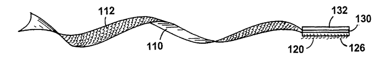
好適な実施態様の詳細な説明 図1を参照すると、包装結合具100は、フック材料の短いストリップ120に取り付けられた不織ループ材料110の長形ストリップを特徴とする。
DETAILED DESCRIPTION OF PREFERRED EMBODIMENTS Referring to FIG. 1, a
不織ループ材料のストリップは、フック係合可能なループ112を備える第1面114と、比較的滑らかな第2面116とを有する。フック材料ストリップ120は、一体成形された固締具要素126を備える第1面122と、滑らかな第2面124とを有する。固締具要素は、フック形でもマッシュルーム形でも良い。フック形固締具要素は、ループ材料に向かって延在する。フックおよびループストリップの滑らかな表面は距離dだけ重なり、ループおよびフックが包装結合具の対向方向に延在するように接合部128に取り付けられる。感圧接着剤層130は、フックストリップ120の滑らかな表面124の残部を被覆する。フックおよびループストリップを向かい合わせに取り付けるため(図1F)、つまり、ループを有するループストリップの表面を、フックを有するフックストリップの表面に取り付けるため、フックストリップ120の基部は、ループストリップ110のループに重なるように、フックがない一体延在部分129を有する。感圧接着剤層130は、シリコン塗布紙などのような剥離ライナー132で被覆される。剥離ライナー132は、長手方向にループ構成要素に重なり、剥離ライナーの一部分が露出して把持できるように構成される。一実施例では、結合具は幅が0.5インチ、つまり寸法wであり、ループストリップは長さが3インチ、つまり寸法lであり、フックストリップは長さが0.75インチ、つまり寸法l1であり、重複領域128は長さが0.4インチ、つまり寸法dであり、すべての構成要素は同じ幅wを有する。ループ材料の厚さは、約0.150インチ〜0.0100インチであり、フック材料の厚さは、約0.100インチ〜0.010インチである。
The strip of nonwoven loop material has a
図1Aを参照すると、図1の包装結合具は、接着剤層により袋の開放端部に取り付けられている。長形不織ループストリップは、袋の開口部周囲に巻かれ、ループストリップの自由端は、ループとフックとを係合させてフックストリップに固定される。包装結合具は、たとえば袋の製造時に、袋に予め固定して結合するか、または剥離層を除去し、接着剤構成要素を袋の材料に圧迫して、使用時に袋に貼付することができる。袋は、合成樹脂または紙から製造される。場合によっては、包装結合具は、感圧接着剤層ではなく、袋の表面に熱溶融できる合成樹脂層を備えることができる。 Referring to FIG. 1A, the wrap tie of FIG. 1 is attached to the open end of the bag by an adhesive layer. The elongated non-woven loop strip is wound around the opening of the bag and the free end of the loop strip is secured to the hook strip by engaging the loop and the hook. The packaging tie can be pre-fixed and bonded to the bag, for example during bag manufacture, or the release layer can be removed and the adhesive component pressed against the bag material and affixed to the bag in use . The bag is manufactured from synthetic resin or paper. In some cases, the wrap tie can include a synthetic resin layer that can be hot melted on the surface of the bag rather than a pressure sensitive adhesive layer.
1回使用した後に製品を使い捨てにする用途の場合、ループ材料は、製品の有効寿命全体で比較的少ない回数、たとえば3〜5回のフック動作サイクルに耐えれば良い。本願の発明人は、こうした用途を「低サイクル」用途と呼ぶ。このカテゴリのループ製品は、一方の面または両面に針で縫って形成されたループを有するニードルド織物を使って有利に製造することができる。場合によっては、材料は、永久的に伸張して安定した状態であり、伸張して、針で縫われた元の状態から100%を超えるか、時には150%以上まで面積が増加する場合がある。針で縫われて伸張させた好ましい材料は、約18〜4デニール、好ましくは6デニールのステープルポリエステル糸から形成される。 For applications where the product is disposable after a single use, the loop material may withstand a relatively small number of times, for example 3-5 hooking cycles, over the entire useful life of the product. The inventors of the present application refer to such applications as “low cycle” applications. This category of loop products can be advantageously manufactured using a needled fabric having loops formed by stitching on one or both sides with a needle. In some cases, the material is permanently stretched and stable, and may stretch and increase in area by more than 100% or sometimes more than 150% from the original state sewn with a needle. . The preferred material sewn and stretched with a needle is formed from staple polyester yarn of about 18-4 denier, preferably 6 denier.
紐でしばるかまたは束ねるなどのようなその他の用途の場合、フック係合可能なループは、より多くのサイクルおよびより高度の応力に耐える必要がある。こうした比較的「高サイクル」、高強度の応用例は、概して、織った材料もしくは編んだ材料を使用して、または低性能条件に適する繊維よりデニールが大きい(つまり頑強さが大きい)繊維を使ってループを形成して作製することが好ましい。このカテゴリのループ 製品は、針で縫った適切なループ織物を50%から100%の伸張範囲で伸張させて、次に安定させて作製することができる。 For other applications, such as tying or bundling, the hook-engageable loop needs to withstand more cycles and higher stresses. These relatively “high cycle”, high strength applications typically use woven or knitted materials, or use fibers that are denier (ie, more robust) than fibers suitable for low performance conditions. It is preferable to form a loop. Loop products in this category can be made with a suitable loop fabric sewn with a needle stretched in the stretch range of 50% to 100% and then stabilized.
特定の応用例では、特別に処理したループ材料を包装結合具に使用する。たとえば、電子装置を保持し、静電気を散逸させる必要がある袋の場合、炭素またはステンレス鋼を含浸させた不織ループを使用すると良い。炭素またはステンレス鋼繊維は、ステープルファイバとブレンドすると、静電気散逸性不織ループ材料を形成することもできる。両面不織ループ材料は、捻るかどうかに関係なくフックに固定できる包装結合具に使用することができる。 In certain applications, specially processed loop materials are used in the wrap tie. For example, for bags that hold electronic devices and need to dissipate static electricity, a non-woven loop impregnated with carbon or stainless steel may be used. Carbon or stainless steel fibers can also form electrostatic dissipative nonwoven loop materials when blended with staple fibers. Double-sided nonwoven loop material can be used in wrap ties that can be secured to hooks regardless of whether they are twisted.
包装結合具のその他の構成としては、特に以下が挙げられる:ループストリップ110は、両方の表面114および116(図1B)にループを有する。ループストリップ110は、ストリップのループ側114(図1C)に密接に結合された接着剤層130により、フックストリップ120全体の滑らかな表面124に重ねて、取り付けられる。フックストリップ120は、ループストリップ110(図1D)の中間に付着し、成形されて伸張した材料である長形フックストリップ 120は、短いループストリップ110(図1E)に取り付けられる。
Other configurations of the wrap tie include, among others, the following:
好ましい実施態様では、不織ループ材料110(図1)は非常に薄いが、なお自己支持し、繊維が絡み合った連続マットの一方の面または両面から延在するループを形成する比較的自由な繊維を有する。好ましい実施態様では、不織ループ材料110は、長手方向および横断方向に伸張されて、図2Aおよび図2Bに示す形態の織物を形成するステープルファイバのニードルド織物を含む。
In a preferred embodiment, the nonwoven loop material 110 (FIG. 1) is very thin but is still relatively self-supporting and forms relatively free fibers that form loops extending from one or both sides of a continuous mat with intertwined fibers. Have In a preferred embodiment, the
こうした織物の場合、マットの個々の繊維は、織物製品のように明確なパターンを取らず、織物マットの平面内で様々な方向に延在する。ループ製品から延在するループは、マットを構成する繊維と同じ繊維だが、マット全体の質量を超えてマットの平面から、概して関連する結節180から、十分に固定されたループツリー250(図2C)の形態で延在する。
In such a fabric, the individual fibers of the mat do not take a distinct pattern as in the fabric product, but extend in various directions within the plane of the fabric mat. The loop extending from the loop product is the same fiber as the fibers that make up the mat, but the well-fixed loop tree 250 (FIG. 2C) from the mat plane, generally from the associated
図2Aに写真で、および図2Bに概念図で示すように、好ましいマットの比較的低密度の繊維領域では、ループ材料110のマットの大多数の繊維は張り詰めており(つまり、緩まずに、局所的に直線である)、ループ材料織物の結節180間に延在する。張り詰めた繊維182は、織物マット170の平面内の少なくとも1方向に加わる張力によりまっすぐになり、結節は、ニードルド不織織物に伸張力が加わる時に生じる滑りおよび凝集によって生じたものである。
As shown in the photograph in FIG. 2A and in the conceptual diagram in FIG. 2B, in the relatively low density fiber region of the preferred mat, the majority of the fibers of the mat of
写真に示すサンプルの結節密度は、特定の正方形領域内で目視可能な結節の数を計算して、1平方インチ当たり約180個の結節と決定された。結節自体は、かなり固く結合しており、数本のモノフィラメント繊維から成り、結節間を通っているように見える張り詰めた繊維によって相互に結合されている。結節間では、薄い繊維マットはあまり緻密ではなく、このマットを通して画像を容易に見ることができる程薄い。低コストの用途では、織物の重量は、1平方ヤード当たり約2オンス未満(1平方メートル当たり68グラム)であることが好ましい。 The nodule density of the sample shown in the photograph was determined to be about 180 nodules per square inch by calculating the number of nodules visible within a particular square area. The nodules themselves are fairly tightly bonded and are composed of several monofilament fibers that are connected to each other by tight fibers that appear to pass between the nodules. Between the nodules, the thin fiber mat is not very dense and is thin enough to easily see the image through this mat. For low cost applications, the weight of the fabric is preferably less than about 2 ounces per square yard (68 grams per square meter).
この特定の実施態様では、マットの繊維は、マットの繊維を直線状態で結合して、織物の面積寸法を安定させ、ループを各々のループに関連する結節に固定するために、ループに対向するマットの側に塗布された水性アクリル結合剤(写真では見えない)によって張り詰めたまっすぐな状態に保持される。結合剤は、概して織物全体の重量の20%〜40%であり、現在好ましい実施態様では、ループ構成要素全体の重量の約1/3を占める。結果として得られる織物は、寸法安定性があり、標準の織物加工技術によりさらに処理するのに適する十分な強度がある。織物が、糊の利いたフェルトのようにわずかに剛性である場合、必要なら、軟化剤または機械的作業により剛性を緩和することができる。 In this particular embodiment, the mat fibers are opposed to the loops in order to join the mat fibers in a straight line to stabilize the fabric area size and secure the loops to the knots associated with each loop. It is held in an upright and straight state by an aqueous acrylic binder (not visible in the picture) applied to the side of the mat. The binder is generally 20% to 40% of the total weight of the fabric and, in the presently preferred embodiment, accounts for about 1/3 of the total weight of the loop component. The resulting fabric is dimensionally stable and has sufficient strength to be suitable for further processing by standard fabric processing techniques. If the fabric is slightly rigid, such as glued felt, it can be relaxed if necessary by a softener or mechanical operation.
図2Cから分かるとおり、ループ112は、繊維状マット170から延在するループ繊維の自立する塊から延在する。塊250は、共通の長形かつ実質的に垂直なトランク252(本明細書で「ループツリー」と呼ぶ)から延在する数本のモノフィラメントループ112を有する。各々のループツリー250は、塊のループが固定されている対応する結節180から延在する。各ツリーのトランク部分252、または各ブシュの基部にある個々のフィラメント間の隙間は、液体結合剤の表面張力の影響下で液体結合剤の灯心現象を生じ、さらに局所的な剛性および強度を与えるための経路を提供する。重要なことに、平面図内の塊の密度は非常に低く、隣接するツリーの「枝」間に十分な空間を残し、係合時にフックおよび湾曲したループ材料を収容することができる。
As can be seen from FIG. 2C, the
適切な不織ループ材料のさらに完全な説明は、米国特許出願第08/922,292号、およびこの出願の一部継続出願として1998年9月3日に「loop material、its manufacture and its use in products」(ループ材料、その製造および製品における使用)というタイトルで提出された関連PCT特許出願に記載されている。これら特許の開示事項は、引用することにより本明細書に包含する。 A more complete description of suitable non-woven loop materials can be found in US patent application Ser. No. 08 / 922,292 and as a continuation-in-part of this application on September 3, 1998, “loop material, its manufacture and its use in. described in a related PCT patent application filed entitled "Products" (loop materials, their manufacture and use in products). The disclosures of these patents are incorporated herein by reference.
図3を参照すると、不織材料110の可撓性は、不織材料110を数回捻ってフック固締具ストリップ120上に固締することを可能にする。ストリップの一方の面にのみループが存在する場合も、フック係合可能なループは捻れのすべての四分区間に存在し、フック構成要素と確実に係合する。さらに、ループストリップの切り裂かれた縁部は、繊維状マット170に一致するように方向付けられ、縁部をフック係合可能にする。
With reference to FIG. 3, the flexibility of the
ループ材料に適合するフックストリップ120を使用する。6デニールのステープルポリエステルファイバから製造された不織ループ材料の場合、フックは、米国、ニューハンプシャー州、マンチェスターのVelcro USA Inc.が市販しているCFM−29と表示されているもので良い。CFM−29フックストリップは、高さがわずか0.015インチ(0.38mm)のフックを有する。特に、フック構成要素が、図1Eに示すように長形の構成要素である場合、フックストリップは、伸張したフック製品である。図4Aおよび図4Bを参照すると、フック製品に側方の伸張が加わる場合、基部ウェブ150の材料の厚さは、図4Aの元の厚さt0から図4Bの減少した厚さt1まで減少する。固締具要素の面密度は、相応に減少する。たとえば、従来の高さが約0.035インチ、列の間隔w0(約0.025インチ)で開始して、図4Bの間隔w1で終わる列に沿った間隔l0が約0.100インチであるタイプのフック形要素の場合、面密度は1/4に変化し、1平方インチ当たり約800個の固締具要素11から1平方インチ当たり約200個の固締具要素になる。より大きいフック密度で開始すると、より高い最終密度は、特定用途のフック動作の必要性に適合するように、低コストで達成することができる。
A
図1の製品は、図5に示す工程および装置により経済的に形成することができる。押出機バレル308は、溶融プラスチック310を融解して、スロット形のダイ312に押し出す。押し出されたプラスチックは、基部ロール316と、公知のフック/ループタイプのストリップ状フック固締具構成要素を成形するように賦形された成形キャビティを含むおよび成形ロール318との間のニップ314に入る。ニップ314内で成形されたストリップ固締具材料は、成形ロール318の外周部周囲を移動して剥離ロール320に達する。剥離ロール320は、完成品300を成形ロールから引っ張って巻取り装置(図示しない)に供給するのを促進する。
The product of FIG. 1 can be economically formed by the process and apparatus shown in FIG. The
図5の装置の一般的な動作に関する詳細は、Kennedy等に付与され、ループ材料で製造された積層物について開示している米国特許第5,260,015号を参照のこと。 For details on the general operation of the apparatus of FIG. 5, see US Pat. No. 5,260,015, granted to Kennedy et al., Which discloses laminates made of loop material.
不織シート材料をフック成形装置の成形部分に供給する方法は、多くの方法が考えられる。図6Aおよび図6Bに示す一実施例では、不織材料350が数本横断方向に離間配置された帯は、基部ロール316の外周部周囲に導入されてニップ314に入り、同時に溶融プラスチック310が、ループ材料の帯間の領域においてニップに入る。スロット形ダイは、プラグと開放ダイ空間とが交互に配置され、これら空間は、不織ループ材料の帯間の空間352を充填して、樹脂と不織材料(図6B)の帯との限られた重複部分を提供して接合部128を形成するように配置されている。不織材料の帯の縁部余白部は、フック固締具354の帯が一体成形される溶融樹脂の縁部余白部に密接に結合する。結合は、ループ材料の繊維をフック材料の溶融樹脂で封入して形成される。したがって、ループ構成要素とフック構成要素とが交互に配置されて接合された帯の複合構造が形成される。
There are many possible methods for supplying the nonwoven sheet material to the forming part of the hook forming apparatus. In one embodiment shown in FIGS. 6A and 6B, several transversely spaced bands of
一実施例では、ウェブ(図7)は、左から開始して3インチ幅の不織ループのストリップ、1.5インチ幅のフック材料のストリップ、6インチ幅の不織ループのストリップ、1.5インチ幅のフック材料のストリップ、および3インチ幅の不織ループのストリップを備える。不織材料およびフック材料が交互になっているストリップは、接合部128で結合して部分的に重複する。重複領域は、たとえば0.4インチ幅である。形成後、ウェブは細断機を通過して、フック部分の中間点AおよびC、および6インチのループ部分の中間点Bで長手方向に切り裂かれる。その結果、長さが連続する4つの複合ウェブが形成され、各々のウェブは、不織ループ材料の比較的広い帯に接合されるフック材料の狭い帯を含む(図8)。
In one embodiment, the web (FIG. 7) has a 3 inch wide nonwoven loop strip, a 1.5 inch wide hook material strip, a 6 inch wide nonwoven loop strip, starting from the left. A strip of hook material 5 inches wide and a strip of
次のステップでは、4つのウェブは塗布ラインを通過し、フックストリップ材料の裏面に感圧接着剤が塗布され、次に、剥離ライナーが接着剤層上に配置されるステップが続く。 In the next step, the four webs pass through the application line, a pressure sensitive adhesive is applied to the back of the hook strip material, and then a release liner is placed on the adhesive layer.
この時点で、4つの連続ウェブ各々が、図9、図10および図12に示すように、線400に沿ってループおよびフック側を貫通し、かつ剥離ライナー132は貫通しないように穿孔切断(キスカット)されて、連の長形袋結合具が形成される。キスカット400の方向は、縦方向に一致する複合ウェブの長手方向軸線402に垂直である。指示された方向に沿ったウェブの断面11−11を図11に示す。
At this point, each of the four continuous webs penetrates the loop and hook side along
包装結合具を製造する別の方法は、フックおよびループ材料の個々に予備成形された帯を超音波シールすることである。この2種類の材料を適切な幅に切り裂かれてそれぞれの縁部を重ね、図13に示す往復超音波溶接機、または図13Aに示す回転超音波溶接機で超音波溶接する。フック材料の裏面には、溶接前に感圧接着剤を塗布する。 Another method of manufacturing a wrap tie is to ultrasonically seal individual preformed bands of hook and loop material. These two kinds of materials are cut into appropriate widths and the respective edges are overlapped, and ultrasonic welding is performed with a reciprocating ultrasonic welding machine shown in FIG. 13 or a rotary ultrasonic welding machine shown in FIG. A pressure sensitive adhesive is applied to the back surface of the hook material before welding.
包装結合具を製造するもう1つの方法は、フックおよびループ材料の予備成形された帯の重複する縁部余白部を熱融着させることである。熱融着は、図14に示す2つの回転ホイール160および162を使って行われる。この2つの回転ホイールは加熱され、ホイール表面にローレットパターンを有する。ホイールは、接合される領域、この場合はループおよびフックの帯の縁部間の重複領域に接触し、この領域を挟む。加熱したホイールは、フック樹脂を融解させて、不織ループの繊維中および繊維周囲にフック樹脂を融着させ、2つの帯の余白部間に結合部を形成する。融解して凝固した樹脂で繊維を機械的に囲むことにより、必要な帯の強度が得られる。
Another method of manufacturing a wrap tie is to heat seal overlapping edge margins of preformed bands of hook and loop material. Thermal fusion is performed using two
異なる種類の樹脂を使用して、フックまたは不織材料を形成しても良い。上記のとおり特定の好ましい場合には、不織材料をポリエステル繊維から製造し、フック材料をポリエチレンから製造する。フックおよびループ材料は、熱特性が異なることが好ましい。たとえば、ポリエチレンは、ポリエステルより低温で融解し、したがってループ材料のポリエステル繊維周囲にフック樹脂を熱融着させて、寸法安定性を有する強力な機械的結合を形成することができる。 Different types of resins may be used to form the hook or nonwoven material. In certain preferred cases as described above, the nonwoven material is made from polyester fibers and the hook material is made from polyethylene. The hook and loop materials preferably have different thermal properties. For example, polyethylene melts at a lower temperature than polyester, and thus a hook resin can be heat fused around the polyester fibers of the loop material to form a strong mechanical bond with dimensional stability.
層130の接着剤は、感圧タイプの接着剤であることが好ましい。場合によっては、層130は、基板上への熱融着に適する合成樹脂で良い。
The adhesive of
共通の剥離ライナー202によって支持される包装結合具は、ロール210状に巻かれる。包装結合具206は、感圧接着剤で剥離ライナーに取り付けられた一方の端部208と、自由端部209とを有する。ロール210は、図15に概要を示す標準ラベル貼機200に供給される。剥離ライナーは、鋭利な角度212で剥離プレート204の周囲を通過して、方向を逆転させる。この剥離ライナーは可撓性であり、容易に方向を変えることができる。しかし、包装結合具は、包装結合具207の縁部が剥離プレート204の周囲で剥離ライナー202をたどらず、剥離ライナーが方向を逆転させる点で突出する特定量の剛性を有する(図15A)。こうして、剥離プレートは、包装結合具を剥離ライナーから自動的に分離する。包装結合具は、ポリエチレンの袋を製造する製袋機上で移動する袋の上に間欠送りするか、または動的に配置することができる。移動する袋に自動的にラベルを分配する方法を図15Bに示す。移動する袋218の前縁217は、光電セル216を動作させる。光電セルは、発光ダイオードである。光電セル216はラベル分配機200に信号を送信し、分配機は、包装結合具206を加速させて、移動する袋218方向に搬送する。包装結合具206が、袋218上の予め決められた位置219に到達するとともに、なお剥離ライナー202に結合していると、タンプローラ(tamp roller)214は、包装結合具206の縁部207を袋218上に圧迫する。包装結合具206、袋218および剥離ライナー202は同じ速度で移動し続け、タンプローラ214は包装結合具を袋上に圧迫する。包装結合具が剥離ライナーから完全に剥離して、袋に取り付けられると、剥離ライナーは移動を停止し、袋は移動し続けて分配機の領域から離れる。次の袋が分配機領域に接近し、光電セル216が作動すると、この工程が再び繰り返される。包装結合具の前進は、精度を高めるために、別個のセンサ(図示しない)により制御される。
A wrap tie supported by a
基材層130を合成樹脂から製造すると、タンプローラ214は、加熱されて包装結合具を袋上に熱融着させる。
When the
もう1つの実施態様では、包装結合具206は、他の包装結合具の上面に積層され(図16A)、剥離可能に一緒に接着された各包装結合具の一方の端部226と、自由端部224とを有する。積層された包装結合具は、分配機の箱220(図16B)内に配置される。分配機の箱は、包装結合具の自由端部224を箱から十分に引き出せるように開口部222を有する。
In another embodiment, the
本発明のその他の特徴および利点としては、以下の1つまたは複数が挙げられる。図7のウェブは、先ず感圧接着剤を塗布され、次に裁断機を通過して長手方向に切り裂かれ、フックおよびループ部分を形成する。不織ループ材料およびフック材料はともに非常に薄く、低価格であり、閉鎖性能が優れているため、この包装結合具は、多くの製品の特に有用な構成要素になる。この包装結合具は、たとえば、上記のプラスチック袋を閉鎖する(図1A)、管またはその他の建築材料を固定する(図18)、ケーブルを束ねる、および束ねたケーブルを固定するなどのために使用することができる。 Other features and advantages of the invention include one or more of the following. The web of FIG. 7 is first applied with a pressure sensitive adhesive and then cut longitudinally through a cutter to form hook and loop portions. Because the non-woven loop material and the hook material are both very thin, inexpensive and have good closure performance, this wrap tie becomes a particularly useful component of many products. This wrap tie is used, for example, to close the above plastic bags (FIG. 1A), to fix tubes or other building materials (FIG. 18), to bundle cables, to fix bundled cables, etc. can do.
本発明のその他の特徴および利点は、以下の請求の範囲内で実現され、請求の範囲に含まれる。 Other features and advantages of the invention will be realized and included within the scope of the following claims.
Claims (56)
Applications Claiming Priority (1)
| Application Number | Priority Date | Filing Date | Title |
|---|---|---|---|
| US09/187,936 US6205623B1 (en) | 1998-11-06 | 1998-11-06 | Composite hook and loop fasteners, and products containing them |
Related Parent Applications (1)
| Application Number | Title | Priority Date | Filing Date |
|---|---|---|---|
| JP2000580481A Division JP2002529123A (en) | 1998-11-06 | 1999-11-05 | Composite hook / loop fasteners, methods of making the same, and products containing the same |
Publications (2)
| Publication Number | Publication Date |
|---|---|
| JP2011037521A true JP2011037521A (en) | 2011-02-24 |
| JP2011037521A5 JP2011037521A5 (en) | 2011-04-07 |
Family
ID=22691097
Family Applications (2)
| Application Number | Title | Priority Date | Filing Date |
|---|---|---|---|
| JP2000580481A Pending JP2002529123A (en) | 1998-11-06 | 1999-11-05 | Composite hook / loop fasteners, methods of making the same, and products containing the same |
| JP2010246350A Pending JP2011037521A (en) | 1998-11-06 | 2010-11-02 | Method for manufacturing composite hook/loop fastening tool |
Family Applications Before (1)
| Application Number | Title | Priority Date | Filing Date |
|---|---|---|---|
| JP2000580481A Pending JP2002529123A (en) | 1998-11-06 | 1999-11-05 | Composite hook / loop fasteners, methods of making the same, and products containing the same |
Country Status (9)
| Country | Link |
|---|---|
| US (5) | US6205623B1 (en) |
| EP (3) | EP1669000B1 (en) |
| JP (2) | JP2002529123A (en) |
| CN (1) | CN100399961C (en) |
| AU (1) | AU762199B2 (en) |
| CA (1) | CA2348852A1 (en) |
| DE (2) | DE69941910D1 (en) |
| ES (3) | ES2337484T3 (en) |
| WO (1) | WO2000027235A1 (en) |
Cited By (5)
| Publication number | Priority date | Publication date | Assignee | Title |
|---|---|---|---|---|
| JP2018000919A (en) * | 2016-07-07 | 2018-01-11 | 台湾百和工業股▲ふん▼有限公司 | Surface bonding fastener |
| JP2019182508A (en) * | 2018-04-13 | 2019-10-24 | 株式会社W | Bag body for holding freshness and manufacturing method thereof |
| JP2019194111A (en) * | 2019-08-06 | 2019-11-07 | 株式会社W | Bag body for holding freshness and manufacturing method thereof |
| US12278468B2 (en) | 2022-02-25 | 2025-04-15 | Velcro Ip Holdings Llc | Support sleeve |
| US12274333B2 (en) | 2018-05-31 | 2025-04-15 | Velcro Ip Holdings Llc | Forming and applying a mated fastener assembly |
Families Citing this family (135)
| Publication number | Priority date | Publication date | Assignee | Title |
|---|---|---|---|---|
| CA2347135C (en) * | 1998-10-02 | 2008-03-25 | 3M Innovative Properties Company | Laminated elastic composites |
| US6205623B1 (en) * | 1998-11-06 | 2001-03-27 | Velcro Industries B.V. | Composite hook and loop fasteners, and products containing them |
| EP1165313B2 (en) * | 1999-02-25 | 2014-09-17 | 3M Innovative Properties Company | Method for the production of a web having discrete stem regions |
| DE60132310T2 (en) | 2000-03-14 | 2009-01-02 | Velcro Industries B.V. | VELCRO SYSTEM |
| WO2001068019A1 (en) * | 2000-03-14 | 2001-09-20 | Velcro Industries B.V. | Stretchable fastener |
| BE1013364A3 (en) * | 2000-03-28 | 2001-12-04 | Alfatex Nv | Method for producing belts made of Velcro |
| US6434802B1 (en) * | 2000-04-20 | 2002-08-20 | Robert E. Pannone | Button replacement device |
| US6551539B1 (en) | 2000-09-19 | 2003-04-22 | Velcro Industries B.V. | Releasable strap |
| ES2236316T3 (en) * | 2000-10-13 | 2005-07-16 | Velcro Industries B.V. | FILLING AND USE OF BAGS THAT CAN BE CLOSED AGAIN. |
| CA2425658A1 (en) * | 2000-10-13 | 2002-04-18 | William H. Shepard | Roll top bag constructions |
| US8678807B2 (en) | 2000-10-24 | 2014-03-25 | Velcro Industries B.V. | Molding apparatus and related methods |
| US6484371B1 (en) * | 2001-02-27 | 2002-11-26 | 3M Innovative Properties Company | High strength, flexible, light weight hook and loop bundling straps |
| US6776528B2 (en) * | 2001-02-28 | 2004-08-17 | David V. Wills | Plastic bag suspension device |
| US7785095B2 (en) | 2001-03-14 | 2010-08-31 | Velcro Industries B.V. | Molding apparatus and related methods |
| US8502069B2 (en) * | 2001-05-18 | 2013-08-06 | Advanced Composite Structures, Llc | Protective cover |
| US6728996B2 (en) * | 2001-10-23 | 2004-05-04 | Robert F. Roscow | Adjustable liner retainer for containers |
| US6763554B1 (en) | 2002-01-22 | 2004-07-20 | Ralph H. Torrey | Self-engaging strap-form tie with special tab |
| US20030224137A1 (en) * | 2002-05-31 | 2003-12-04 | Han Bong Chung | Fastener and method of manufacturing the same |
| US20060143875A1 (en) * | 2002-07-11 | 2006-07-06 | Vicky Kunold | Device for closing bags |
| US7785691B2 (en) * | 2002-08-20 | 2010-08-31 | Velcro Industries B.V. | Flexible building construction laminates with fasteners |
| US20040058121A1 (en) * | 2002-09-13 | 2004-03-25 | Ideative Product Ventures, Inc. | Flexible bundling and labeling device |
| US20040181156A1 (en) * | 2002-12-16 | 2004-09-16 | Kingsford Howard A. | Inflatable products and methods of their formation and use |
| WO2004058122A1 (en) | 2002-12-16 | 2004-07-15 | Velcro Industries B.V. | Medical wraps |
| US7118648B2 (en) * | 2003-01-08 | 2006-10-10 | Sdf Group, Llc | Paper Strap |
| US20070068641A1 (en) * | 2003-01-10 | 2007-03-29 | Sdf Group, Llc | Strap and Methods for Making and Using Such |
| US7052565B2 (en) * | 2003-01-27 | 2006-05-30 | 3M Innovative Properties Company | Web constructions with severed elongate strands |
| US7132144B2 (en) * | 2003-02-28 | 2006-11-07 | Velcro Industries B.V. | Fastener tapes |
| USD496854S1 (en) | 2003-03-21 | 2004-10-05 | 3M Innovative Properties Company | Bundling strap |
| USD500671S1 (en) | 2003-03-21 | 2005-01-11 | 3M Innovative Properties Company | Self-engaging bundling strap provided with machine readable code |
| USD505064S1 (en) | 2003-03-21 | 2005-05-17 | 3M Innovative Properties Company | Bundling strap |
| USD505063S1 (en) | 2003-03-21 | 2005-05-17 | 3M Innovative Properties Company | Bundling strap |
| USD511450S1 (en) | 2003-03-21 | 2005-11-15 | 3M Innovative Properties Company | Self-engaging bundling strap provided with machine readable code |
| US7096544B2 (en) * | 2003-04-12 | 2006-08-29 | Kevin Timothy Lusardi | Wrap-it |
| KR20060008907A (en) * | 2003-04-21 | 2006-01-27 | 인덕터썸코포레이션 | Electromagnetic pump |
| DE20306351U1 (en) | 2003-04-23 | 2003-06-26 | Koester GmbH & Co. KG, 96146 Altendorf | Cable band is produced in a strip form and is wrapped around bundle of cable or hoses |
| US20040261230A1 (en) * | 2003-06-30 | 2004-12-30 | Neeb Alexander J. | Elastic fastening system |
| US7172008B2 (en) * | 2003-09-18 | 2007-02-06 | Velcro Industries B.V. | Hook fasteners and methods of making the same |
| US7373699B2 (en) * | 2003-10-15 | 2008-05-20 | Velcro Industries B.V. | Plastic sheet reinforcement |
| US8079995B2 (en) * | 2003-11-06 | 2011-12-20 | Velcro Industries B.V. | Composite fastener products |
| US20050170157A1 (en) * | 2004-01-29 | 2005-08-04 | Armela Luis P. | Composite products and methods of forming such products |
| US7950114B2 (en) * | 2004-03-10 | 2011-05-31 | Leonard Arnold Duffy | Self-adhering device and method |
| US7254874B2 (en) * | 2004-03-10 | 2007-08-14 | Leonard Arnold Duffy | Molded surface fasteners and attachment methods |
| US7200898B2 (en) * | 2004-06-12 | 2007-04-10 | Augustus Sclalfani | Clamping system for safety lines |
| WO2006026734A2 (en) | 2004-08-31 | 2006-03-09 | Obermeyer Henry K | High strength joining system for fiber reinforced composites |
| US7608070B2 (en) * | 2004-09-30 | 2009-10-27 | Kimberly-Clark Worldwide, Inc. | Foam-based fasteners |
| US7636987B2 (en) * | 2004-10-22 | 2009-12-29 | Tama Plastic Industry | Wrapping material with fastener |
| FR2880401B1 (en) * | 2004-12-30 | 2007-02-23 | Eurocopter France | DEVICE FOR FIXING ELONGATE ELEMENTS TO A STRUCTURE |
| US20060148376A1 (en) * | 2004-12-30 | 2006-07-06 | Well Made Toy Manufacturing Corp. | Closure for stuffed toy and method |
| US7601284B2 (en) * | 2005-04-06 | 2009-10-13 | Velcro Industries B.V. | Molding fastener elements on folded substrate |
| DE602006001713D1 (en) * | 2005-05-05 | 2008-08-21 | Velcro Ind | FORMS OF CONNECTING SHARES ON SUBSTRATES |
| US7640637B2 (en) | 2005-11-01 | 2010-01-05 | Kimberly-Clark Worldwide, Inc. | Methods to modify the fibrous landing layer of a foam based fastener and products made from the same |
| US20100088859A1 (en) * | 2005-11-29 | 2010-04-15 | Tama Plastic Industry | Wrapping materal with fastener |
| US7870652B2 (en) | 2005-12-22 | 2011-01-18 | The Procter & Gamble Company | Fasteners having improved comfort |
| BRPI0620320A2 (en) | 2005-12-22 | 2011-11-08 | Procter & Gamble | Relatively rigid closures |
| TWM312918U (en) * | 2006-09-28 | 2007-06-01 | Taiwan Paiho Ltd | Viscid fastener |
| US8047560B2 (en) * | 2007-07-03 | 2011-11-01 | Avery Dennison Corporation | Retention cover for an inflatable object |
| US8615854B2 (en) | 2007-11-06 | 2013-12-31 | Michael P. Fennell | Fixturing apparatus |
| US9289865B2 (en) | 2007-11-06 | 2016-03-22 | Michael P. Fennell | Fixturing apparatus |
| US9629422B2 (en) | 2007-11-06 | 2017-04-25 | Michael P. Fennell | Fixturing apparatus |
| US10477927B2 (en) | 2007-11-06 | 2019-11-19 | Michael P. Fennell | RFID enhanced fixturing apparatus |
| US8256068B2 (en) * | 2007-11-16 | 2012-09-04 | Panduit Corp. | Microhook fastener apparatus |
| US20100192331A1 (en) * | 2008-05-27 | 2010-08-05 | Panduit Corp. | Hook and Loop Tie with a Non-Slip Area |
| US8701252B2 (en) * | 2008-05-27 | 2014-04-22 | Panduit Corp. | Hook and loop tie with a non-slip area |
| US8276243B2 (en) * | 2008-05-27 | 2012-10-02 | Panduit Corp. | Hook and loop tie with a non-slip area |
| TWI370726B (en) * | 2008-10-21 | 2012-08-21 | Taiwan Paiho Ltd | Fastening strap and manufacturing method thereof |
| TWI403282B (en) * | 2008-12-05 | 2013-08-01 | Taiwan Paiho Ltd | Fastening assembly and cushion having fastening assembly |
| TW201021738A (en) * | 2008-12-12 | 2010-06-16 | Taiwan Paiho Ltd | Fastening assembly and cushion having fastening assembly |
| TW201023783A (en) * | 2008-12-26 | 2010-07-01 | Taiwan Paiho Ltd | Fastening assembly and cushion having fastening assembly |
| US8784722B2 (en) * | 2009-01-20 | 2014-07-22 | Gerald ROCHA | Method and apparatus for producing hook fasteners |
| US9788674B2 (en) * | 2009-03-17 | 2017-10-17 | Joseph Rocco Pacione | Covering module |
| US9119444B2 (en) * | 2009-05-01 | 2015-09-01 | Chittaranjan Narandas Nirmel | Versatile hook-and-loop fastener system |
| US20110120391A1 (en) * | 2009-11-24 | 2011-05-26 | Marie-Antoinette Novy | Dry dog bag |
| USD662266S1 (en) * | 2009-12-03 | 2012-06-19 | Dold Kathryn M | Pet collar |
| US20110146032A1 (en) * | 2009-12-10 | 2011-06-23 | Ossur Hf | Strapping system |
| CA2692891C (en) * | 2010-02-25 | 2012-10-09 | The Procter & Gamble Company | Absorbent article with improved garment-like character |
| CA2693130C (en) * | 2010-02-25 | 2012-10-09 | The Procter & Gamble Company | Absorbent article with improved garment-like character |
| CA2692638C (en) * | 2010-02-25 | 2011-05-10 | The Procter & Gamble Company | Absorbent article with improved garment-like character |
| CA2692679C (en) * | 2010-02-25 | 2013-04-30 | The Procter & Gamble Company | Absorbent article with improved garment-like character |
| EP2467308A1 (en) | 2010-04-12 | 2012-06-27 | Velcro Industries B.V. | Reclosable pouch |
| WO2011130020A1 (en) | 2010-04-15 | 2011-10-20 | Velcro Industries B.V. | Methods of forming composite materials |
| EP2592960B1 (en) | 2010-07-16 | 2016-06-22 | Gerald Rocha | Dimensionally flexible touch fastener strip |
| USD667291S1 (en) | 2010-08-27 | 2012-09-18 | Cjd Llc | Strap for cord management |
| BE1019478A3 (en) * | 2010-09-08 | 2012-07-03 | Alfatex Nv | METHOD FOR THE PRODUCTION OF VELVET TIE, APPARATUS THEREFOR, AND VELVET TIE. |
| USD667043S1 (en) * | 2010-09-17 | 2012-09-11 | Couch Iii Quest C | Extendable strap |
| PL2621441T3 (en) * | 2010-09-28 | 2018-10-31 | Avery Dennison Corporation | Diaper closure system |
| US20130052400A1 (en) * | 2011-08-30 | 2013-02-28 | Kuo-Ian CHENG | Transparent mat reclosable fastener |
| USD682070S1 (en) | 2011-09-11 | 2013-05-14 | Cjd Llc | Strap with cord attachment mechanism for a cord management system |
| USD675505S1 (en) | 2011-09-13 | 2013-02-05 | Cjd Llc | Strap with hook and loop closure for a cord management system |
| USD675904S1 (en) | 2011-09-16 | 2013-02-12 | Cjd Llc | Strap with cord attachment mechanism and hook and loop closure for a cord management system |
| JP5924519B2 (en) * | 2011-11-01 | 2016-05-25 | 株式会社中條 | Hook and loop fastener device |
| US9084701B2 (en) | 2011-11-10 | 2015-07-21 | The Procter & Gamble Company | Absorbent articles with hook and loop fastening systems |
| TWI503084B (en) * | 2012-02-01 | 2015-10-11 | Taiwan Paiho Ltd | A foldable hook member for a foamed article, a foamed article comprising the foldable hook member, and a method of manufacturing the same |
| CN107518532A (en) * | 2012-03-23 | 2017-12-29 | 科卢斯博知识产权有限公司 | Bulk amorphous alloys fastener |
| US9399333B2 (en) | 2012-04-18 | 2016-07-26 | Velcro BVBA | Forming laminated touch fasteners |
| US9591896B2 (en) | 2012-05-16 | 2017-03-14 | 3M Innovative Properties Company | Method of making a mechanical fastener using diverging disks |
| CN107259720A (en) | 2012-05-16 | 2017-10-20 | 3M创新有限公司 | The method that machanical fastener is manufactured using crown surface |
| US9475205B2 (en) | 2012-05-18 | 2016-10-25 | 3M Innovative Properties Company | Method of making a mechanical fastener and apparatus including a roller with protrusions |
| US20140000784A1 (en) | 2012-06-29 | 2014-01-02 | Shrish Yashwant Rane | Method for Producing a Multi-Layer Nonwoven Web Having Enhanced Mechanical Properties |
| US9056032B2 (en) | 2012-06-29 | 2015-06-16 | The Procter & Gamble Company | Wearable article with outwardmost layer of multicomponent fiber nonwoven providing enhanced mechanical features |
| US20140000070A1 (en) | 2012-06-29 | 2014-01-02 | Arman Ashraf | Fastening System Having Multicomponent Fiber Component Providing Enhanced Separation Resistance |
| EP2906070B1 (en) | 2012-10-15 | 2016-06-29 | Velcro Bvba | Touch fastening |
| WO2014107661A1 (en) * | 2013-01-07 | 2014-07-10 | Nite Ize, Inc. | Systems and methods for an object with a bonded adhesive strip |
| KR101305374B1 (en) * | 2013-02-08 | 2013-09-06 | 스타시스코리아(주) | Conductive band |
| US9314962B2 (en) | 2013-05-10 | 2016-04-19 | 3M Innovative Properties Company | Method of separating strands on a stretching surface |
| US9366038B1 (en) * | 2013-07-19 | 2016-06-14 | Closed Loop Recycling, Llc | Absorbent floor system and method of installation |
| US9649792B2 (en) | 2013-10-15 | 2017-05-16 | Velcro BVBA | Forming longitudinally pleated products |
| US20160318666A1 (en) * | 2013-12-12 | 2016-11-03 | Printpack Illinois, Inc. | Reclose Concept of Roll & Close for Pillow & Side Gusset Bags |
| US9072343B1 (en) * | 2014-01-02 | 2015-07-07 | John W. Ogilvie | Multigrip touch closure fasteners |
| FR3019445B1 (en) | 2014-04-03 | 2019-04-12 | Aplix | METHOD FOR ASSEMBLING AT LEAST TWO ASSEMBLIES AND CORRESPONDING ASSEMBLED STRUCTURE |
| WO2015173171A1 (en) | 2014-05-12 | 2015-11-19 | Velcro Industries B.V. | Reusable closure system for packaging |
| US10518525B2 (en) | 2014-07-10 | 2019-12-31 | Velcro BVBA | Printing plate connection systems |
| CN104172671B (en) * | 2014-08-18 | 2016-07-27 | 无锡百和织造股份有限公司 | Automatic forming device for sticky buckle ribbon |
| DE102014113959A1 (en) | 2014-09-26 | 2016-03-31 | Fresenius Medical Care Deutschland Gmbh | A method of customizing a medical product and labeled product present under film or in a bag |
| US10167111B2 (en) | 2014-12-19 | 2019-01-01 | Velcro BVBA | Tamper-evident reusable package closure |
| RU2604585C1 (en) * | 2015-05-26 | 2016-12-10 | Александр Геннадьевич Нюркин | Method for velcro performing |
| US10548458B1 (en) * | 2015-12-04 | 2020-02-04 | Jeremy Joseph Sankey | Tethered cleaning tool for a kitchen sink |
| US9958070B2 (en) * | 2015-12-18 | 2018-05-01 | Velcro BVBA | Membrane edge sealing |
| US9980538B2 (en) | 2015-12-29 | 2018-05-29 | Lear Corporation | Eco loop closure fabric |
| USD836903S1 (en) * | 2016-03-15 | 2019-01-01 | Perry T Lindsey | Shoe safety strap |
| USD819951S1 (en) * | 2016-03-15 | 2018-06-12 | Perry T. Lindsey | Shoe strap |
| CN107585419A (en) * | 2016-07-07 | 2018-01-16 | 台湾百和工业股份有限公司 | Surface joint fastener |
| US20180084887A1 (en) * | 2016-09-27 | 2018-03-29 | Elaine West | Elastic Hair Band with Adhesive and Non-Adhesive Properties |
| WO2018112229A1 (en) | 2016-12-14 | 2018-06-21 | Eam Corporation | Absorbent laminates, absorbent cores and disposable articles utilizing the absorbent laminates, and related methods |
| AU2017428895B2 (en) * | 2017-08-23 | 2021-09-09 | Fuchs Petrolub Se | Improvements to protective covers for conduits such as cables and/or hoses |
| CN108149393B (en) * | 2018-02-12 | 2021-09-28 | 福建省莆田嘉裕华制鞋工业有限公司 | Pattern sewing machine processing method for leather product with hook and fur surface |
| WO2019157700A1 (en) * | 2018-02-14 | 2019-08-22 | Abb Schweiz Ag | A tying device for cable/wire harness and a method for manufacturing tying devices |
| JP6991362B2 (en) | 2018-04-25 | 2022-01-12 | スリーエム イノベイティブ プロパティズ カンパニー | How to manufacture a laminate |
| CN111946704B (en) * | 2019-05-17 | 2023-04-25 | 台湾百和工业股份有限公司 | Method for manufacturing fasteners and fasteners |
| USD986048S1 (en) * | 2019-08-19 | 2023-05-16 | Sim Design Limited | Bottle strap |
| US11425970B2 (en) | 2020-03-17 | 2022-08-30 | Brady Worldwide, Inc. | Printable hook and loop structure |
| US20210321734A1 (en) * | 2021-05-14 | 2021-10-21 | Alphonzo Hamilton | Pest-proof bag |
| WO2023114955A1 (en) * | 2021-12-16 | 2023-06-22 | Mayo Foundation For Medical Education And Research | System and method for securing lines |
| CA3255219A1 (en) | 2022-06-16 | 2023-12-21 | Velcro Ip Holdings Llc | Flexible touch fastener products |
| WO2024020924A1 (en) | 2022-07-28 | 2024-02-01 | The Procter & Gamble Company | Absorbent article with fastening component for disposal |
| FR3140522B1 (en) * | 2022-10-11 | 2025-06-20 | Aplix Sa | Improved retaining device and method of manufacturing the same |
Citations (4)
| Publication number | Priority date | Publication date | Assignee | Title |
|---|---|---|---|---|
| JPH06509727A (en) * | 1991-08-16 | 1994-11-02 | フエルクロ・インダストリーズ・ベスローテム・ヴエンノツトシヤツプ | Laminated hook fastener |
| JPH08299032A (en) * | 1995-05-09 | 1996-11-19 | Ykk Kk | Molded surface fastener |
| JPH09315A (en) * | 1995-06-20 | 1997-01-07 | Ykk Kk | Molded surface fastener and manufacturing method thereof |
| JPH10117815A (en) * | 1996-08-30 | 1998-05-12 | Ykk Corp | Surface fastener band and manufacturing method thereof |
Family Cites Families (101)
| Publication number | Priority date | Publication date | Assignee | Title |
|---|---|---|---|---|
| US3000386A (en) | 1958-12-03 | 1961-09-19 | State University Of Iowa | Expansible frame structure |
| US3000384A (en) | 1960-01-04 | 1961-09-19 | Jr Eber F Piers | Fastener tie |
| NL285479A (en) | 1961-11-14 | |||
| US3322325A (en) | 1962-01-30 | 1967-05-30 | Roy L Bush | Bag seal utilizing pressure sensitive tape having weakened transverse zones |
| US3312583A (en) | 1963-10-02 | 1967-04-04 | James J Rochlis | Apertured and staggered molded pile product |
| US3426363A (en) * | 1965-02-17 | 1969-02-11 | American Velcro Inc | Composite length of pile fabric sheet material |
| US3594863A (en) | 1969-07-10 | 1971-07-27 | American Velcro Inc | Apparatus for molding plastic shapes in molding recesses formed in a moving endless belt |
| US3594865A (en) | 1969-07-10 | 1971-07-27 | American Velcro Inc | Apparatus for molding plastic shapes in molding recesses formed in moving endless wire dies |
| CH537815A (en) | 1971-05-10 | 1973-06-15 | Caratsch Hans Peter | Device for applying a thermoplastic material to a flat structure in the form of deposits provided at a distance from one another |
| US3762000A (en) | 1971-11-11 | 1973-10-02 | M Menzin | Production of a continuous molded plastic strip |
| US3752619A (en) | 1971-11-11 | 1973-08-14 | American Velcro Inc | Production of a continuous molded plastic strip |
| US3758657A (en) | 1971-12-01 | 1973-09-11 | American Velcro Inc | Production of a continuous molded plastic strip |
| US3991708A (en) | 1975-06-23 | 1976-11-16 | Moore Business Forms, Inc. | Gravure-type adhesive applicator |
| US4149540A (en) | 1975-07-02 | 1979-04-17 | Velcro Usa Inc. | Separable cinch fastener |
| US4097634A (en) | 1976-04-19 | 1978-06-27 | Minnesota Mining And Manufacturing Company | Thermoplastic resin molding of complex decorative relief |
| US4088136A (en) | 1976-08-26 | 1978-05-09 | American Velcro Inc. | Separable fastener for catheter tubes and the like |
| US4074397A (en) * | 1976-10-15 | 1978-02-21 | Rosin Stanley A | Device for securing cords, tubes, and the like |
| US4465486A (en) * | 1977-12-27 | 1984-08-14 | E. R. Squibb & Sons, Inc. | Closures for open ended ostomy pouch |
| US4247967A (en) | 1979-03-16 | 1981-02-03 | Excaliber, Incorporated | Slip-resistant binding |
| JPS5746049Y2 (en) | 1979-12-04 | 1982-10-09 | ||
| JPS5687172A (en) | 1979-12-18 | 1981-07-15 | Ricoh Co Ltd | Print medium control system for automatic inserter |
| US4569348A (en) | 1980-02-22 | 1986-02-11 | Velcro Usa Inc. | Catheter tube holder strap |
| US4592118A (en) * | 1983-11-18 | 1986-06-03 | Barnhart Industries, Inc. | Fasteners for apparel and methods of manufacturing them |
| US4794028A (en) | 1984-04-16 | 1988-12-27 | Velcro Industries B.V. | Method for continuously producing a multi-hook fastner member and product of the method |
| US4615084A (en) | 1984-08-21 | 1986-10-07 | Erblok Associates | Multiple hook fastener media and method and system for making |
| IE57148B1 (en) * | 1984-11-20 | 1992-05-06 | Velcro Ind | Separable fasteners as well as method and apparatus for adapting separable fasteners for attachment to other objects |
| US5015251A (en) | 1984-11-30 | 1991-05-14 | Alimed, Inc. | Medical fastener strap |
| FR2576191B1 (en) | 1985-01-23 | 1990-11-23 | Picardie Lainiere | NOVEL PRODUCT FOR HOT GLUE PRESSURE ON FLAT ITEMS AND METHOD OF MANUFACTURING SUCH A PRODUCT |
| US4761318A (en) | 1985-04-15 | 1988-08-02 | Minnesota Mining And Manufacturing Company | Loop fastener portion with thermoplastic resin attaching and anchoring layer |
| US4933224A (en) | 1985-07-17 | 1990-06-12 | Velcro Industries, B.V. | Method for adapting separable fasteners for attachment to other objects |
| US4955981A (en) | 1985-10-24 | 1990-09-11 | Velcro Industries B.V. | Reclosable bag having hook and loop sealing strips |
| US4672722A (en) | 1986-04-28 | 1987-06-16 | Jmw Textiles | Single tape closure construction |
| US4706914A (en) * | 1986-07-25 | 1987-11-17 | Minnesota Mining And Manufacturing Company | Attaching assembly |
| US4854735A (en) | 1987-11-04 | 1989-08-08 | Ironclad, Corporation | Plastic film bag with integral plastic film tie element, and associated fabrication methods |
| KR940006314B1 (en) | 1987-12-15 | 1994-07-16 | 가부시끼가이샤 구라레 | Fastener component |
| JPH0711621Y2 (en) * | 1987-12-15 | 1995-03-22 | 株式会社クラレ | Fastening member |
| US4894060A (en) | 1988-01-11 | 1990-01-16 | Minnesota Mining And Manufacturing Company | Disposable diaper with improved hook fastener portion |
| US4986265A (en) | 1988-02-16 | 1991-01-22 | Caponi Ronald E | Protective cover for cast |
| US4815172A (en) | 1988-04-06 | 1989-03-28 | Ward Clinton G | Fastening device |
| US5142743A (en) | 1988-09-02 | 1992-09-01 | Hahn Blake S | Adjustable bundling device |
| US4939818A (en) | 1988-09-02 | 1990-07-10 | Hahn Blake S | Adjustable bundling device |
| US6406468B1 (en) | 1988-12-20 | 2002-06-18 | Kimberly-Clark Worldwide, Inc. | Mechanical fastening tapes and method for their construction |
| US5230851A (en) | 1989-01-31 | 1993-07-27 | The Procter & Gamble Company | Process of manufacturing a refastenable mechanical fastening system |
| US5180534A (en) | 1990-12-21 | 1993-01-19 | The Procter & Gamble Company | Process of manufacturing a refastenable mechanical fastening system |
| US4999067A (en) * | 1989-02-13 | 1991-03-12 | Erblok Associates | Method for making a hermaphrodite hook and loop fasteners |
| US4913560A (en) | 1989-03-08 | 1990-04-03 | Mobil Oil Corporation | Stretchy sticky tape bag tie closure |
| US4906108A (en) | 1989-03-08 | 1990-03-06 | Mobil Oil Corporation | Corrugated sticky tape bag tie closure |
| US5048158A (en) | 1990-01-12 | 1991-09-17 | Robert Koerner | Keeper for coiled items |
| JPH0637717Y2 (en) * | 1990-03-23 | 1994-10-05 | モリト株式会社 | Unity band |
| GB2248052B (en) | 1990-08-31 | 1994-06-08 | Instance Ltd David J | Bag ties and manufacture thereof |
| US5168603A (en) | 1991-04-08 | 1992-12-08 | The Siemon Company | Bundling tie |
| US5133112A (en) | 1991-04-25 | 1992-07-28 | Gomez Acevedo Hector H | Closure device |
| PL170275B1 (en) | 1991-06-21 | 1996-11-29 | Procter & Gamble | Method of manufacturing the connecting element PL PL PL PL PL PL |
| US5989204A (en) | 1991-09-27 | 1999-11-23 | Kinetic Concepts, Inc. | Foot-mounted venous compression device |
| US5200245A (en) | 1991-10-25 | 1993-04-06 | Brodrick Jr Louis T | Fastener |
| US5231738A (en) | 1991-12-12 | 1993-08-03 | Kuraray Co., Ltd. | Mixed hook/loop separable fastener and process for its production |
| US5293884A (en) | 1992-01-08 | 1994-03-15 | Full Moon Fashion Accessories, Inc. | Loop strap hair tie |
| US5614057A (en) * | 1992-02-19 | 1997-03-25 | Mim Industries, Inc. | Automatic ultrasonic fusing system |
| US5172980A (en) | 1992-05-19 | 1992-12-22 | Velcro Industries, B.V. | Reclosable bag having hook and loop sealing strips |
| JP2744384B2 (en) * | 1992-07-22 | 1998-04-28 | ワイケイケイ株式会社 | Method and apparatus for manufacturing engaging member having back member on back surface |
| US5300058A (en) | 1992-12-10 | 1994-04-05 | The Procter & Gamble Company | Disposable absorbent article having an improved mechanical fastening system |
| KR970009710B1 (en) | 1992-12-30 | 1997-06-17 | 킴벌리-클라크 코포레이션 | Garment attachment system |
| US5321855A (en) | 1993-03-12 | 1994-06-21 | Ronald J. Chisena | Fastening system for pairing socks, hosiery and gloves |
| DE4328656A1 (en) * | 1993-08-26 | 1995-03-02 | Bayer Ag | Flame retardant, stress crack resistant polycarbonate ABS molding compounds |
| US5403413A (en) | 1993-10-01 | 1995-04-04 | Yoshida Kogyo K.K. | Apparatus and method for manufacturing surface fastener bands |
| ATE169462T1 (en) | 1993-10-15 | 1998-08-15 | Procter & Gamble | ELASTIC STRETCHABLE MECHANICAL FASTENING ARRANGEMENT |
| US5505747A (en) | 1994-01-13 | 1996-04-09 | Minnesota Mining And Manufacturing Company | Method of making an abrasive article |
| EP0675183B1 (en) | 1994-03-30 | 1997-08-27 | KUFNER TEXTILWERKE GmbH | Process for patterned coating of flexible sheets with hot-melt adhesives |
| US5762645A (en) | 1994-06-06 | 1998-06-09 | The Procter & Gamble Company | Fastening device and method of use |
| US5595567A (en) | 1994-08-09 | 1997-01-21 | The Procter & Gamble Company | Nonwoven female component for refastenable fastening device |
| US5636503A (en) | 1994-08-23 | 1997-06-10 | Broken Arrow Specialties | Horse blanket keeper |
| US5452877A (en) | 1994-09-20 | 1995-09-26 | Riffle; Mary A. | Beach umbrella anchor bag |
| US5586371A (en) | 1994-11-08 | 1996-12-24 | The Procter & Gamble Company | Method for manufacturing refastenable fastening systems including a female loop fastening component and the product produced therefrom |
| US5476702A (en) | 1994-12-28 | 1995-12-19 | Kimberly-Clark Corporation | Fastening system for absorbent article and method of manufacture |
| US5606781A (en) | 1995-02-17 | 1997-03-04 | Velcro Industries, B.V. | Separable fastener having a bald perimeter rib bounded by fastening elements |
| US5595014A (en) | 1995-02-21 | 1997-01-21 | Moore; Clifton H. | Fishing rod tie |
| US5636414A (en) * | 1995-02-24 | 1997-06-10 | Litchholt; John J. | Two mechanism mechanical fastener |
| US5692271A (en) | 1995-03-07 | 1997-12-02 | Velcro Industries B.V. | Enhanced flexibility fastener, method and apparatus for its making, and product incorporating it |
| US5620769A (en) | 1995-05-02 | 1997-04-15 | Ykk Corporation | Molded surface fastener and method for manufacturing the same |
| US5635503A (en) * | 1995-06-07 | 1997-06-03 | Bristol-Myers Squibb Company | Dihydropyridine npy antagonists: piperazine derivatives |
| US5604961A (en) | 1995-07-11 | 1997-02-25 | Fox Ridge Enterprises, Inc. | Multiple purpose fastening device, system and method |
| GB2303566A (en) * | 1995-07-21 | 1997-02-26 | Ykk Europ Ltd | Self-sdhesive fastener |
| US5672404A (en) | 1995-09-07 | 1997-09-30 | Minnesota Mining And Manufacturing Company | Attachment strips |
| DE29602362U1 (en) | 1996-02-01 | 1997-01-16 | Merten, Helmut Wolfgang, Dipl.-Soz., 20255 Hamburg | Universal strap |
| US5908680A (en) | 1996-03-05 | 1999-06-01 | Minnesota Mining And Manufacturing Company | Replaceable roll covers with repositionable pressure sensitive adhesive |
| US5624429A (en) | 1996-03-06 | 1997-04-29 | Kimberly-Clark Corporation | Mechanical fastening system with grip tab |
| US5897545A (en) | 1996-04-02 | 1999-04-27 | The Procter & Gamble Company | Elastomeric side panel for use with convertible absorbent articles |
| FR2750319B1 (en) | 1996-07-01 | 1999-01-15 | Tape Ind | MALE MOBILE ELEMENT OF MECHANICAL FASTENERS FOR PANTIES |
| US5868407A (en) | 1996-08-27 | 1999-02-09 | Roese; William C. | Steerable cart with hand brake |
| JPH10137008A (en) * | 1996-11-15 | 1998-05-26 | Kao Corp | Tape with mechanical hook |
| US5868987A (en) | 1997-06-19 | 1999-02-09 | Minnesotamining And Manufacturing | Superimposed embossing of capped stem mechanical fastener structures |
| US6106922A (en) | 1997-10-03 | 2000-08-22 | 3M Innovative Company | Coextruded mechanical fastener constructions |
| US6051094A (en) | 1997-10-06 | 2000-04-18 | 3M Innovative Properties Company | Closure system for disposable absorbent article |
| US6060009A (en) | 1998-02-18 | 2000-05-09 | 3M Innovative Properties Company | Method of laminate formation |
| US6453635B1 (en) * | 1998-07-15 | 2002-09-24 | Powertrusion International, Inc. | Composite utility poles and methods of manufacture |
| US6205623B1 (en) * | 1998-11-06 | 2001-03-27 | Velcro Industries B.V. | Composite hook and loop fasteners, and products containing them |
| EP1165313B2 (en) | 1999-02-25 | 2014-09-17 | 3M Innovative Properties Company | Method for the production of a web having discrete stem regions |
| DE60132310T2 (en) | 2000-03-14 | 2009-01-02 | Velcro Industries B.V. | VELCRO SYSTEM |
| JP3699896B2 (en) | 2000-06-30 | 2005-09-28 | Ykk株式会社 | Seat fasteners |
| JP2002040047A (en) * | 2000-07-25 | 2002-02-06 | Denso Corp | Capacitive physical quantity detecting sensor |
| JP4636071B2 (en) | 2005-03-24 | 2011-02-23 | Dic株式会社 | Color material selection assisting device, method and program |
-
1998
- 1998-11-06 US US09/187,936 patent/US6205623B1/en not_active Expired - Lifetime
-
1999
- 1999-11-05 DE DE69941910T patent/DE69941910D1/en not_active Expired - Lifetime
- 1999-11-05 EP EP06002497A patent/EP1669000B1/en not_active Expired - Lifetime
- 1999-11-05 JP JP2000580481A patent/JP2002529123A/en active Pending
- 1999-11-05 CN CNB998130044A patent/CN100399961C/en not_active Expired - Lifetime
- 1999-11-05 AU AU13375/00A patent/AU762199B2/en not_active Ceased
- 1999-11-05 EP EP09172111A patent/EP2140775B1/en not_active Expired - Lifetime
- 1999-11-05 ES ES06002497T patent/ES2337484T3/en not_active Expired - Lifetime
- 1999-11-05 DE DE69929816T patent/DE69929816T2/en not_active Expired - Lifetime
- 1999-11-05 CA CA002348852A patent/CA2348852A1/en not_active Abandoned
- 1999-11-05 WO PCT/US1999/025748 patent/WO2000027235A1/en not_active Ceased
- 1999-11-05 ES ES09172111T patent/ES2371604T3/en not_active Expired - Lifetime
- 1999-11-05 ES ES99956854T patent/ES2258859T3/en not_active Expired - Lifetime
- 1999-11-05 EP EP99956854A patent/EP1143819B1/en not_active Expired - Lifetime
-
2001
- 2001-03-26 US US09/818,197 patent/US6481063B2/en not_active Expired - Lifetime
-
2002
- 2002-10-15 US US10/271,494 patent/US8778243B2/en not_active Expired - Fee Related
-
2004
- 2004-08-18 US US10/921,449 patent/US20050015938A1/en not_active Abandoned
-
2010
- 2010-11-02 JP JP2010246350A patent/JP2011037521A/en active Pending
-
2013
- 2013-05-09 US US13/890,751 patent/US8549714B1/en not_active Expired - Fee Related
Patent Citations (4)
| Publication number | Priority date | Publication date | Assignee | Title |
|---|---|---|---|---|
| JPH06509727A (en) * | 1991-08-16 | 1994-11-02 | フエルクロ・インダストリーズ・ベスローテム・ヴエンノツトシヤツプ | Laminated hook fastener |
| JPH08299032A (en) * | 1995-05-09 | 1996-11-19 | Ykk Kk | Molded surface fastener |
| JPH09315A (en) * | 1995-06-20 | 1997-01-07 | Ykk Kk | Molded surface fastener and manufacturing method thereof |
| JPH10117815A (en) * | 1996-08-30 | 1998-05-12 | Ykk Corp | Surface fastener band and manufacturing method thereof |
Cited By (5)
| Publication number | Priority date | Publication date | Assignee | Title |
|---|---|---|---|---|
| JP2018000919A (en) * | 2016-07-07 | 2018-01-11 | 台湾百和工業股▲ふん▼有限公司 | Surface bonding fastener |
| JP2019182508A (en) * | 2018-04-13 | 2019-10-24 | 株式会社W | Bag body for holding freshness and manufacturing method thereof |
| US12274333B2 (en) | 2018-05-31 | 2025-04-15 | Velcro Ip Holdings Llc | Forming and applying a mated fastener assembly |
| JP2019194111A (en) * | 2019-08-06 | 2019-11-07 | 株式会社W | Bag body for holding freshness and manufacturing method thereof |
| US12278468B2 (en) | 2022-02-25 | 2025-04-15 | Velcro Ip Holdings Llc | Support sleeve |
Also Published As
| Publication number | Publication date |
|---|---|
| ES2371604T3 (en) | 2012-01-05 |
| US6481063B2 (en) | 2002-11-19 |
| DE69941910D1 (en) | 2010-02-25 |
| EP1143819A1 (en) | 2001-10-17 |
| DE69929816T2 (en) | 2006-09-14 |
| US20050015938A1 (en) | 2005-01-27 |
| EP2140775A1 (en) | 2010-01-06 |
| US20030074768A1 (en) | 2003-04-24 |
| US20130239371A1 (en) | 2013-09-19 |
| US20010022012A1 (en) | 2001-09-20 |
| EP2140775B1 (en) | 2011-08-17 |
| EP1143819A4 (en) | 2004-03-24 |
| JP2002529123A (en) | 2002-09-10 |
| ES2337484T3 (en) | 2010-04-26 |
| DE69929816D1 (en) | 2006-04-20 |
| CN100399961C (en) | 2008-07-09 |
| AU762199B2 (en) | 2003-06-19 |
| US8549714B1 (en) | 2013-10-08 |
| EP1143819B1 (en) | 2006-02-08 |
| WO2000027235A1 (en) | 2000-05-18 |
| EP1669000A1 (en) | 2006-06-14 |
| US6205623B1 (en) | 2001-03-27 |
| ES2258859T3 (en) | 2006-09-01 |
| US8778243B2 (en) | 2014-07-15 |
| AU1337500A (en) | 2000-05-29 |
| CN1325280A (en) | 2001-12-05 |
| EP1669000B1 (en) | 2010-01-06 |
| CA2348852A1 (en) | 2000-05-18 |
Similar Documents
| Publication | Publication Date | Title |
|---|---|---|
| JP2011037521A (en) | Method for manufacturing composite hook/loop fastening tool | |
| JP2002529169A (en) | Touch fasteners, their manufacture and products incorporating them | |
| US7406810B2 (en) | Reclosable packaging | |
| US6656403B1 (en) | Securing loop materials | |
| US7395583B2 (en) | Hook engageable loops | |
| EP1304213B1 (en) | Touch fasteners and their manufacture | |
| EP1286605B1 (en) | Loops material for a hook and loop fastener | |
| EP1681155A2 (en) | Touch fasteners and their manufacture | |
| JP2507402B2 (en) | Tea bag and manufacturing method thereof | |
| MXPA01004533A (en) | Touch fasteners, their manufacture, and products incorporating them |
Legal Events
| Date | Code | Title | Description |
|---|---|---|---|
| A521 | Request for written amendment filed |
Free format text: JAPANESE INTERMEDIATE CODE: A523 Effective date: 20110209 |
|
| A131 | Notification of reasons for refusal |
Free format text: JAPANESE INTERMEDIATE CODE: A131 Effective date: 20120808 |
|
| A601 | Written request for extension of time |
Free format text: JAPANESE INTERMEDIATE CODE: A601 Effective date: 20121107 |
|
| A602 | Written permission of extension of time |
Free format text: JAPANESE INTERMEDIATE CODE: A602 Effective date: 20121112 |
|
| A601 | Written request for extension of time |
Free format text: JAPANESE INTERMEDIATE CODE: A601 Effective date: 20121206 |
|
| A602 | Written permission of extension of time |
Free format text: JAPANESE INTERMEDIATE CODE: A602 Effective date: 20121211 |
|
| A02 | Decision of refusal |
Free format text: JAPANESE INTERMEDIATE CODE: A02 Effective date: 20130415 |