JP2010508904A - Cardiac lead with retractable helix - Google Patents
Cardiac lead with retractable helix Download PDFInfo
- Publication number
- JP2010508904A JP2010508904A JP2009535373A JP2009535373A JP2010508904A JP 2010508904 A JP2010508904 A JP 2010508904A JP 2009535373 A JP2009535373 A JP 2009535373A JP 2009535373 A JP2009535373 A JP 2009535373A JP 2010508904 A JP2010508904 A JP 2010508904A
- Authority
- JP
- Japan
- Prior art keywords
- distal
- management system
- helix
- lead
- electrode
- Prior art date
- Legal status (The legal status is an assumption and is not a legal conclusion. Google has not performed a legal analysis and makes no representation as to the accuracy of the status listed.)
- Pending
Links
- 230000000747 cardiac effect Effects 0.000 title claims abstract description 40
- 210000002216 heart Anatomy 0.000 claims abstract description 40
- 230000033764 rhythmic process Effects 0.000 claims abstract description 40
- 239000003814 drug Substances 0.000 claims description 7
- 230000007246 mechanism Effects 0.000 claims description 7
- 210000005166 vasculature Anatomy 0.000 claims description 7
- 238000004873 anchoring Methods 0.000 claims description 6
- 238000003780 insertion Methods 0.000 claims description 4
- 230000037431 insertion Effects 0.000 claims description 4
- 229940124597 therapeutic agent Drugs 0.000 claims description 3
- 230000000087 stabilizing effect Effects 0.000 abstract 1
- 210000001519 tissue Anatomy 0.000 description 22
- 230000002107 myocardial effect Effects 0.000 description 16
- 239000004020 conductor Substances 0.000 description 9
- 238000000034 method Methods 0.000 description 7
- 210000005242 cardiac chamber Anatomy 0.000 description 5
- 238000012986 modification Methods 0.000 description 4
- 230000004048 modification Effects 0.000 description 4
- 210000004165 myocardium Anatomy 0.000 description 3
- 210000005245 right atrium Anatomy 0.000 description 3
- 210000005241 right ventricle Anatomy 0.000 description 3
- 210000002620 vena cava superior Anatomy 0.000 description 3
- 230000002861 ventricular Effects 0.000 description 3
- 239000011248 coating agent Substances 0.000 description 2
- 238000000576 coating method Methods 0.000 description 2
- 229940079593 drug Drugs 0.000 description 2
- 238000002513 implantation Methods 0.000 description 2
- 210000005240 left ventricle Anatomy 0.000 description 2
- 239000000463 material Substances 0.000 description 2
- 229910001000 nickel titanium Inorganic materials 0.000 description 2
- BASFCYQUMIYNBI-UHFFFAOYSA-N platinum Chemical compound [Pt] BASFCYQUMIYNBI-UHFFFAOYSA-N 0.000 description 2
- 230000002441 reversible effect Effects 0.000 description 2
- 230000002792 vascular Effects 0.000 description 2
- 208000011616 HELIX syndrome Diseases 0.000 description 1
- 206010061218 Inflammation Diseases 0.000 description 1
- 229910001260 Pt alloy Inorganic materials 0.000 description 1
- RTAQQCXQSZGOHL-UHFFFAOYSA-N Titanium Chemical compound [Ti] RTAQQCXQSZGOHL-UHFFFAOYSA-N 0.000 description 1
- 238000007792 addition Methods 0.000 description 1
- 229910045601 alloy Inorganic materials 0.000 description 1
- 239000000956 alloy Substances 0.000 description 1
- 230000004075 alteration Effects 0.000 description 1
- 229920000249 biocompatible polymer Polymers 0.000 description 1
- 230000017531 blood circulation Effects 0.000 description 1
- 239000003795 chemical substances by application Substances 0.000 description 1
- 238000004891 communication Methods 0.000 description 1
- 239000000470 constituent Substances 0.000 description 1
- 230000008602 contraction Effects 0.000 description 1
- 238000013461 design Methods 0.000 description 1
- 238000004070 electrodeposition Methods 0.000 description 1
- 230000010247 heart contraction Effects 0.000 description 1
- 210000005003 heart tissue Anatomy 0.000 description 1
- 230000004054 inflammatory process Effects 0.000 description 1
- 239000011810 insulating material Substances 0.000 description 1
- 230000002452 interceptive effect Effects 0.000 description 1
- 230000001788 irregular Effects 0.000 description 1
- 210000005246 left atrium Anatomy 0.000 description 1
- 230000000670 limiting effect Effects 0.000 description 1
- 238000004519 manufacturing process Methods 0.000 description 1
- HLXZNVUGXRDIFK-UHFFFAOYSA-N nickel titanium Chemical compound [Ti].[Ti].[Ti].[Ti].[Ti].[Ti].[Ti].[Ti].[Ti].[Ti].[Ti].[Ni].[Ni].[Ni].[Ni].[Ni].[Ni].[Ni].[Ni].[Ni].[Ni].[Ni].[Ni].[Ni].[Ni] HLXZNVUGXRDIFK-UHFFFAOYSA-N 0.000 description 1
- 239000012811 non-conductive material Substances 0.000 description 1
- 229910052697 platinum Inorganic materials 0.000 description 1
- 229920002635 polyurethane Polymers 0.000 description 1
- 239000004814 polyurethane Substances 0.000 description 1
- 230000008569 process Effects 0.000 description 1
- 230000001681 protective effect Effects 0.000 description 1
- 210000001147 pulmonary artery Anatomy 0.000 description 1
- 210000003102 pulmonary valve Anatomy 0.000 description 1
- 230000000717 retained effect Effects 0.000 description 1
- 238000010561 standard procedure Methods 0.000 description 1
- 125000002345 steroid group Chemical group 0.000 description 1
- 230000000638 stimulation Effects 0.000 description 1
- 229910052719 titanium Inorganic materials 0.000 description 1
- 239000010936 titanium Substances 0.000 description 1
- 230000007704 transition Effects 0.000 description 1
- 210000003462 vein Anatomy 0.000 description 1
- 210000000596 ventricular septum Anatomy 0.000 description 1
Images


Classifications
-
- A—HUMAN NECESSITIES
- A61—MEDICAL OR VETERINARY SCIENCE; HYGIENE
- A61N—ELECTROTHERAPY; MAGNETOTHERAPY; RADIATION THERAPY; ULTRASOUND THERAPY
- A61N1/00—Electrotherapy; Circuits therefor
- A61N1/02—Details
- A61N1/04—Electrodes
- A61N1/05—Electrodes for implantation or insertion into the body, e.g. heart electrode
- A61N1/056—Transvascular endocardial electrode systems
- A61N1/057—Anchoring means; Means for fixing the head inside the heart
- A61N1/0573—Anchoring means; Means for fixing the head inside the heart chacterised by means penetrating the heart tissue, e.g. helix needle or hook
- A61N1/0575—Anchoring means; Means for fixing the head inside the heart chacterised by means penetrating the heart tissue, e.g. helix needle or hook with drug delivery
-
- A—HUMAN NECESSITIES
- A61—MEDICAL OR VETERINARY SCIENCE; HYGIENE
- A61N—ELECTROTHERAPY; MAGNETOTHERAPY; RADIATION THERAPY; ULTRASOUND THERAPY
- A61N1/00—Electrotherapy; Circuits therefor
- A61N1/02—Details
- A61N1/04—Electrodes
- A61N1/05—Electrodes for implantation or insertion into the body, e.g. heart electrode
- A61N1/056—Transvascular endocardial electrode systems
- A61N1/057—Anchoring means; Means for fixing the head inside the heart
- A61N2001/0578—Anchoring means; Means for fixing the head inside the heart having means for removal or extraction
Landscapes
- Health & Medical Sciences (AREA)
- Cardiology (AREA)
- Heart & Thoracic Surgery (AREA)
- Vascular Medicine (AREA)
- Engineering & Computer Science (AREA)
- Biomedical Technology (AREA)
- Nuclear Medicine, Radiotherapy & Molecular Imaging (AREA)
- Radiology & Medical Imaging (AREA)
- Life Sciences & Earth Sciences (AREA)
- Animal Behavior & Ethology (AREA)
- General Health & Medical Sciences (AREA)
- Public Health (AREA)
- Veterinary Medicine (AREA)
- Electrotherapy Devices (AREA)
Abstract
心臓用リードを患者の心臓内に固定するための心リズム管理システムが提供される。本発明によれば、心リズム管理システムは、リードを患者の心臓内の標的場所に固定すると共に安定させるための固定用螺旋体を有する。固定用螺旋体は、電極に被さった第1の位置から心臓用リードの遠位端部に対して遠位側に配置される位置まで伸長するようになっている。 A cardiac rhythm management system is provided for securing a cardiac lead within a patient's heart. In accordance with the present invention, the cardiac rhythm management system includes a fixation helix for fixing and stabilizing the lead at a target location in the patient's heart. The fixation helix extends from a first position over the electrode to a position disposed distal to the distal end of the cardiac lead.
Description
〔関連出願の説明〕
本願は、2006年11月8日に出願された米国特許出願第11/557,815号(発明の名称:CARDIAC LEAD WITH A RETRACTABLE HELIX)の優先権主張出願であり、この米国特許出願を参照により引用し、その記載内容全体を本明細書の一部とする。
[Description of related applications]
The present application is a priority claim application of US Patent Application No. 11 / 557,815 (Title of Invention: CARDIAC LEAD WITH A RETRACTABLE HELIX) filed on Nov. 8, 2006. Cited and the entire contents of which are incorporated herein by reference.
本発明は、医療用リードの分野に関する。本発明は、特に、心臓用リードの遠位端を心腔内に固定するための伸長したり引っ込んだりすることができる螺旋体を有する医療用電気リードに関する。 The present invention relates to the field of medical leads. In particular, the present invention relates to a medical electrical lead having a helical body that can be extended and retracted to secure the distal end of the cardiac lead within the heart chamber.
心臓の不規則収縮を電気的刺激で治療する植え込み型医療器具が周知である。例示的な植え込み型器具は、除細動器やペースメーカである。除細動器及びペースメーカ用の種々の形式の電気リードが提案されたが、これらの多くは、経静脈的に配置される。かかるリードは、静脈アクセス部位で患者の血管系中に導入され、静脈を通って、リードの電極が植え込まれ又は標的冠状組織に接触する部位まで移動する。経静脈的に配置されるリード用の電極は、右心房又は右心室の心筋層中に植え込まれるのが良く又は変形例として、冠状静脈系内の別の場所に植え込まれても良い。 Implantable medical devices that treat irregular heart contractions with electrical stimulation are well known. Exemplary implantable devices are defibrillators and pacemakers. Various types of electrical leads have been proposed for defibrillators and pacemakers, many of which are placed intravenously. Such a lead is introduced into the patient's vasculature at the venous access site and travels through the vein to the site where the electrode of the lead is implanted or contacts the target coronary tissue. The lead electrode placed intravenously may be implanted in the myocardium of the right atrium or right ventricle, or alternatively, may be implanted elsewhere in the coronary venous system.
所望の植え込み部位のところでの上述した形式のリードの固定を容易にするために種々の技術が用いられてきた。心腔内に植え込まれるリードの場合、固定技術は、リードを押して電極が植え込まれている場所から離脱させようとする生まれつきの心臓の運動及び逆行性血流に耐えるのに十分安定した固定を提供すべきである。加うるに、必要な場合又は所望の場合、植え込み後に、リード及び固定構造体の再位置決め又は取り外しを可能にしたり容易にしたりすることが望ましい。 Various techniques have been used to facilitate fixation of leads of the type described above at the desired implantation site. In the case of a lead implanted in the heart chamber, the fixation technique is stable enough to withstand the inherent heart motion and retrograde blood flow that pushes the lead away from where the electrode is implanted. Should be provided. In addition, if necessary or desired, it may be desirable to allow or facilitate repositioning or removal of the lead and fixation structure after implantation.
リードを固定するための螺旋体が、当該技術分野において知られている。また、螺旋体の直径が大きければ大きいほど、この螺旋体がもたらす固定がより安定するということが認識されている。典型的なリードの構成では、固定用螺旋体をリード本体又はカテーテルの内部の位置に伸長させたりこれから引っ込めたりする。したがって、リード本体を固定するために用いられる固定用螺旋体のサイズは、リード本体又はカテーテルの直径によって制限される。リード内に配置される電極のサイズ及び形式も又、この構成によって制限される。 Helicals for securing leads are known in the art. It has also been recognized that the larger the diameter of the helix, the more stable the fixation provided by this helix. In a typical lead configuration, the fixation helix is extended to or retracted from a location within the lead body or catheter. Accordingly, the size of the fixation helix used to secure the lead body is limited by the diameter of the lead body or catheter. The size and type of electrodes placed in the leads is also limited by this configuration.
したがって、心臓用リードを冠状動静脈系内に固定する改良型器具及び方法が要望され続けている。特に、当該技術分野においては、リード電極を標的冠状の場所内に効果的に固定したり安定させたりする一方で、依然としてリードの次の取り出しを可能にする固定方式が要望されている。 Accordingly, there continues to be a need for improved devices and methods for securing cardiac leads within the coronary arteriovenous system. In particular, there is a need in the art for an anchoring scheme that effectively anchors and stabilizes the lead electrode within the target coronal location while still allowing subsequent removal of the lead.
本発明は、一実施形態によれば、患者の心臓に治療を施すようになったパルス発生器と、電気リード本体、近位部分、及び遠位部分を備えた電気リードとを有する心リズム管理システムである。近位部分は、パルス発生器に作動的に結合され、遠位部分は、心腔内に配置されている。心リズム管理組立体は、電気リードの遠位端に設けられた少なくとも1つの電極と、固定用螺旋体とを更に有し、固定用螺旋体は、電極を含む電気リードの遠位部分に被さった第1の位置から、電気リードの遠位端に対して遠位側に配置された第2の位置まで延びるようになっている。本発明の別の実施形態では、心リズム管理システムは、固定用螺旋体を第1の位置から第2の位置に操作するようになった作動機構体を更に有する。 The present invention, according to one embodiment, is a cardiac rhythm management comprising a pulse generator adapted to treat a patient's heart and an electrical lead comprising an electrical lead body, a proximal portion, and a distal portion. System. The proximal portion is operably coupled to the pulse generator and the distal portion is disposed within the heart chamber. The cardiac rhythm management assembly further includes at least one electrode disposed at a distal end of the electrical lead and a securing helix, the securing helix covering a distal portion of the electrical lead including the electrode. It extends from one position to a second position disposed distal to the distal end of the electrical lead. In another embodiment of the invention, the cardiac rhythm management system further comprises an actuating mechanism adapted to manipulate the fixation helix from a first position to a second position.
本発明の別の実施形態によれば、心リズム管理システムは、患者の心臓に治療を施すようになったパルス発生器を有し、心リズム管理システムは、近位部分及び遠位部分を備えた電気リードを更に有し、近位部分は、パルス発生器に作動的に結合され、遠位部分は、心臓の腔内に配置され、心リズム管理システムは更に、近位端及び遠位端を備えた固定用螺旋体を有し、固定用螺旋体は、電気リードに結合され、心リズム管理システムは更に、電気リードの遠位端に設けられた少なくとも1つの電極を有する。電極は、固定用螺旋体内に配置され、固定用螺旋体内に配置された遠位側位置から近位側位置に動くようになっている。 According to another embodiment of the present invention, a cardiac rhythm management system comprises a pulse generator adapted to treat a patient's heart, the cardiac rhythm management system comprising a proximal portion and a distal portion. A proximal portion is operatively coupled to the pulse generator, the distal portion is disposed within the heart cavity, and the cardiac rhythm management system further includes a proximal end and a distal end The fixation helix is coupled to the electrical lead, and the cardiac rhythm management system further includes at least one electrode disposed at the distal end of the electrical lead. The electrode is disposed within the fixation helix and is adapted to move from a distal position disposed within the fixation helix to a proximal position.
本発明の更に別の実施形態によれば、心臓の腔内に位置する部位に配置されるリードであって、電気リード本体と、近位部分と、遠位部分と、少なくとも1つの電極と、電極に被せられていて、リードの遠位端を心臓の腔内に固定する固定手段とを有することを特徴とするリードが提供される。 According to yet another embodiment of the present invention, a lead disposed at a site located within the heart cavity, the electrical lead body, a proximal portion, a distal portion, at least one electrode, A lead is provided that includes an anchoring means over the electrode and securing the distal end of the lead within the heart cavity.
本発明の更に別の実施形態によれば、心リズム管理システムは、患者の心臓に治療を施すようになったパルス発生器と、リード本体、近位部分、及び遠位部分を備えた電気リードとを有し、遠位部分は、心臓の腔内に配置され、心リズム管理システムは、電気リードの遠位端のところに設けられた少なくとも1つの電極と、電極を含む電気リードの遠位部分に被せられた固定用螺旋体とを更に有する。固定用螺旋体は、患者の血管系中へのリードの挿入中、組織にひっかからないよう形作られている。 In accordance with yet another embodiment of the present invention, a cardiac rhythm management system includes a pulse generator adapted to treat a patient's heart and an electrical lead comprising a lead body, a proximal portion, and a distal portion. And the distal portion is disposed within the heart cavity, and the cardiac rhythm management system includes at least one electrode disposed at the distal end of the electrical lead and a distal of the electrical lead including the electrode. And a fixing helix over the portion. The fixation helix is shaped so that it does not catch tissue during insertion of the lead into the patient's vasculature.
多くの実施形態が開示されるが、本発明の更に別の実施形態は、本発明の例示の実施形態を示すと共に説明する以下の詳細な説明から当業者には明らかになろう。したがって、図面の記載及び詳細な説明は、性質上例示であって、本発明を限定するものではないと考えられるべきである。 While many embodiments are disclosed, still other embodiments of the present invention will become apparent to those skilled in the art from the following detailed description, which illustrates and describes exemplary embodiments of the present invention. Accordingly, the description and detailed description of the drawings should be considered as illustrative in nature and not as limiting the present invention.
本発明について種々の改造例及び変形例が可能であるが、特定の実施形態が、図面に一例として示されており、これらにつき以下に詳細に説明する。しかしながら、本発明は、記載した特定の実施形態に限定されることはない。これとは異なり、本発明は、特許請求の範囲に記載された本発明の範囲に属するあらゆる改造例、均等例及び変形例を包含するものである。 While the invention is susceptible to various modifications and alternative forms, specific embodiments have been shown by way of example in the drawings and are described in detail below. However, the invention is not limited to the specific embodiments described. On the contrary, the invention is intended to cover all modifications, equivalents, and variations belonging to the scope of the present invention as set forth in the claims.
図1Aは、本発明の心リズム管理システム4を示す。心リズム管理システム4は、パルス発生器6を有し、このパルス発生器は、上大静脈12を通って患者の心臓10内に配備された電気リード8に結合されている。図1に示されているように、心臓10は、上大静脈12、右心房14、心尖17を備えた右心室16、心室中隔18、肺動脈弁24を備えた肺動脈22に通じる心室流出路20、左心室26及び左心房28を有している。一実施形態では、リード8は、電気パルス、例えばペーシングパルス又は除細動を、右心室尖17の近くで右心室16内に位置決めされた電極36経由で心臓10に送るようになっている。
FIG. 1A shows a cardiac rhythm management system 4 of the present invention. The cardiac rhythm management system 4 includes a pulse generator 6 that is coupled through an superior vena cava 12 to an
リード8は、細長い可撓性のリード本体40、近位部分42及び遠位部分44を有している。リード8は、パルス発生器6からのエネルギーを心臓10に伝え、更に心臓10からの信号を受け取る1つ又は2つ以上の導体、例えばコイル状導体を更に有している。加うるに、リード8は、共通ラジアル(co-radial )設計のものであるのが良い。リード8は、導体を絶縁する外側絶縁材45を更に有している。1つ又は複数の導体は、1つ又は2つ以上の電極、例えば電極36に結合されている。本発明の一実施形態では、リード8は、案内要素、例えばガイドワイヤ又はスタイレットを受け入れるルーメンを有している。
The
近位部分42は、パルス発生器6に作動的に結合されている。加うるに、近位部分42は、当該技術分野において周知である技術を用いて、リード8の遠位部分44を操作して血管系中に通し、電極36を含むリード8の遠位端46を心腔内の標的場所内に位置決めするよう動作可能である。リード8は、当該技術分野において知られているように心臓内の別の場所、例えば心臓の左側(例えば、左心室)に配備できることは理解されよう。
本発明の一実施形態では、遠位部分44は、上大静脈12及び右心房14を通って心臓10の右心室尖17の近くに位置する標的位置まで案内される。リード8の遠位部分44は、リード本体40の遠位端46に設けられた少なくとも1つの電極36を有する。リード8の遠位端46は、固定器具を用いて心筋層に固定される。本発明の実施形態によれば、固定器具は、リード8の遠位端46に配置された電極36を含むリード本体40の遠位部分44上で伸長したり引っ込んだりする固定用螺旋体である。
In one embodiment of the invention, the distal portion 44 is guided through the superior vena cava 12 and the right atrium 14 to a target location located near the right ventricular apex 17 of the heart 10. The distal portion 44 of the
図2A〜図2Dは、本発明のリード8の遠位部分44の種々の図である。リード8の遠位部分44は、遠位組立体71、遠位シース75、電極80及び固定用螺旋体82を含む遠位端領域60を有する。電極80は、遠位シース75内に収納されており、電極先端部84を有する。固定用螺旋体82は、遠位組立体71に結合され、遠位シース75及び電極80に被せられている。本発明の別の実施形態によれば、固定用螺旋体82は、シース75に回転可能に被せられる。
2A-2D are various views of the distal portion 44 of the
図2B及び図2Dに示されているように、電極80は、遠位シース75内に収納されており、リード本体40の遠位端46に配置されている。電極80は、遠位シース75の内面に沿って軸方向に配置された導体86を介してリード8の遠位端46と電気的連絡(導通)状態にある。導体86は、リード8の遠位部分44内に設けられた二次導体コイル87を介してリード本体40内の導体コイルと導通する。一実施形態では、遠位シース75の外面は、例えば当該技術分野において知られているような非導電性材料(例えば、パラリエン(paralyene))で被覆されている。これは、電気ノイズ又は「微細な振動(chatter)」が電極80により生じた電気パルスを妨害するのを阻止する。電極80は、当該技術分野において知られているように任意の形態のものであって良い。一実施形態によれば、電極80は、全体として半球形の形態をしている。別の実施形態によれば、電極80は、スロット付き先端電極であり、電極先端部84及びリザーバ88を有する。リザーバ88は、薬剤を保持したり、薬剤を心臓10内の標的場所に位置する心筋組織に投与したりするようになっている。本発明の一実施形態では、薬剤は、標的場所の炎症を軽減するステロイドである。変形例として、薬剤は、治療を患者の心臓10に施すための当該技術分野において知られている他の薬剤又は治療薬であっても良い。さらに、理解されるように、本発明の特徴を利用して他の医療器具、例えばセンサ等を位置決めしたり固定したりするようになっていても良い。
As shown in FIGS. 2B and 2D, the electrode 80 is housed within the distal sheath 75 and disposed at the distal end 46 of the lead body 40. The electrode 80 is in electrical communication with the distal end 46 of the
図2B及び図2Dに最も良く示されているように、遠位組立体71は、遠位シャフト92、遠位組立体ハウジング93及び回転可能なピン94を有している。ピン94は、遠位シース75に設けられた溝96(図2A及び図2Cに最も良く示されている)内を移動する。溝96は、停止領域98,99を有し、固定用螺旋体82の前進及び回転を制御する。ピン94を遠位組立体71内で作動させると、固定用螺旋体82は、近位側又は遠位側の方向に遠位シース75及び電極80上で回転する。図2A〜図2Dでは、回しピン100が、内部導体コイルを回転させるために用いられ、かくして、遠位組立体71内に配置されているピン94は、固定用螺旋体82を遠位側の方向に遠位シース75及び電極80上で回転させる。
As best shown in FIGS. 2B and 2D, the
固定用螺旋体82は、近位端102、遠位端104及び先端部106を有する。本発明の実施形態によれば、固定用螺旋体82は、遠位シース75内に配置されている電極80とは独立して回転可能に伸長したり引っ込んだりする。固定用螺旋体82は、引っ込み位置108(図2Aに示されている)から伸長位置110(図2Bに示されている)に伸長したり引っ込んだりし、シース75に対して動く。遠位シース75に設けられている溝96は、螺旋体の伸長と引っ込みの両方のための停止領域98,99を提供することにより、固定用螺旋体の前進を制御する。遠位回転力が遠位組立体71に加えられると、停止領域99は、固定用螺旋体がその意図した伸長位置110を越えて遠すぎる位置へ伸長されるのを阻止する。同様に、近位回転力を加えると、停止領域98は、固定用螺旋体が遠位シース75上で遠すぎる位置へ引っ込められるのを阻止する。これらの特徴により、固定用螺旋体82を標的場所でのリード8の再位置決め中、容易に引っ込めたり再配備することができる。加うるに、これら特徴により、固定用螺旋体82を制御された仕方で伸長させたり引っ込めたりすることができる。一実施形態では、伸長位置110は、リード8の遠位端46に対して遠位側に位置している。別の実施形態では、伸長位置110は、電極先端部84に対して遠位側に位置している。別の実施形態では、固定用螺旋体82は、電極先端部84から測定して約1.5mm〜約2mmの距離にわたって伸長することができる。さらに別の実施形態では、固定用螺旋体82の遠位端104は、引っ込み位置108にあるとき、電極先端部84と半径方向に整列する。
The fixation helix 82 has a
本発明の実施形態によれば、固定用螺旋体82は、リード8が血管系中を案内されて標的部位に位置決めされると、引っ込み位置108にある。この位置では、先端部106は、以下に説明する図3で最も良く示されており、リード8が血管系中を案内されているとき血管組織にひっかからない。製造の際、先端部106は、螺旋体80の内部に向かって内方に撓むよう研削される。リード8が患者の血管系中を案内されているとき、先端部106を血管組織にひっかけないようにすることができるのは、この形態である。本発明の実施形態では、先端部106は、1つのファセット(小面)を有している。本発明の別の実施形態では、螺旋体82の先端部106は、標的場所で心筋組織に係合する2つ又は3つ以上のファセットを有するのが良い。本発明の変形実施形態によれば、先端部106の形状は、ピラミッド状、円錐形、尖っていない形状、丸形又は当該技術分野において知られている別の形状であるよう形成されても良い。螺旋体82がいったん伸長位置110にある場合、先端部106は、その内方撓みにもかかわらず、標的場所で心筋組織に係合することができる。
According to an embodiment of the present invention, the fixation helix 82 is in the retracted position 108 when the
本発明により、より大きな(大径)固定用螺旋体82を用いて標的場所で所定の直径を持つリード8を固定することができる。というのは、固定用螺旋体82は、リード本体40の遠位部分44を覆って配置されているからである。螺旋体82を保護する目的で設けられる外側カテーテル又は案内部材は、螺旋体先端部106がその引っ込み位置108では組織にひっかからないので、不要である。大径螺旋体は、心臓の収縮に一段と耐えることができ、かくして、リードを固定する上で一層安定性がある。本発明の一実施形態では、固定用螺旋体82の外径は、約0.045インチ(1.143mm)から約0.092インチ(2.337mm)の範囲にある。本発明の別の実施形態では、固定用螺旋体82の外径は、約0.045インチ(1.143mm)から約0.050インチ(1.270mm)の範囲にある。さらに別の実施形態では、固定用螺旋体の外径は、約0.050インチ(1.270mm)から約0.079インチ(2.007mm)の範囲にある。さらに別の実施形態では、固定用螺旋体の外径は、約0.079インチ(2.007mm)から0.092インチ(2.337mm)の範囲にある。
According to the present invention, a
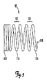
図3は、本発明の実施形態としての固定用螺旋体82を示している。螺旋体82は、近位端102、遠位端104及び近位端と遠位端との間に延びる螺旋本体110を有している。遠位端104のところには、螺旋先端部106が設けられている。螺旋体の構成材料としては、次のもの、即ち、ニチノール、NiTi合金、チタン、スプリングテンパー316SS、MP35N、白金又は白金合金、ポリウレタン、生体適合性ポリマー又は当該技術分野において知られている別の材料が挙げられるが、これらには限定されない。一実施形態では、螺旋体は、非導電性外側被膜を備えたワイヤコイルである。非導電性被膜は、ワイヤ螺旋体の100%を被覆し、厚さが約4マイクロインチ(0.106マイクロメートル)〜約5マイクロインチ(0.127マイクロメートル)の範囲にある。変形実施形態では、コイルそれ自体は、非導電性である。螺旋体82のターン(一回り)107は、螺旋本体110の特定長さにわたり一定ピッチ(周期数)を維持する。本発明では、ピッチは、約0.030インチ(0.762mm)から約0.050インチ(1.270mm)の範囲にある。加うるに、螺旋体82の近位端102は、螺旋本体110の特定長さよりも密に巻かれたピッチを有する最低で2つの完全ターンを有する。螺旋体82の密巻き近位端102から一定ピッチを持つ螺旋本体110まで滑らかな移行部が存在する。
FIG. 3 shows a fixing helix 82 as an embodiment of the present invention. The helix 82 has a
螺旋体82が第2の位置110にあるとき、螺旋体先端部106は、標的場所で心筋組織に係合することができる。本発明の実施形態によれば、螺旋体82は、図2A〜図2Dに示されているように、リード8の遠位部分60内に配置された遠位組立体71の作動により標的場所で心筋組織に回転可能に係合する。螺旋先端部106は、これが標的場所に固定されて安定するまで心筋組織内に回転する。
When the helix 82 is in the
図4に示された本発明の実施形態によれば、スタイレット114が、リード8に設けられたルーメン116内に挿入される。スタイレット114は、リード8の遠位端領域60に設けられた遠位組立体71を作動させるのに用いられる。スタイレット114は、遠位端部118を有し、このスタイレットをリード8の近位部分42のところで作動させる。本発明の一実施形態によれば、スタイレット114の遠位端部118は、遠位シャフト92に設けられたスロット120に回転可能に嵌合するようになっており、このスロットは、スタイレット114の遠位端部118を回転可能に受け入れるようになっている。スタイレット114が遠位シャフト92に設けられているスロット120に係合しているとき、スタイレット114を用いて遠位組立体71を回転させ、かくして固定用螺旋体82を回転させる。遠位シャフト92を遠位側の方向に押すと共に回すことにより、ピン94は、遠位シャフト75に設けられている溝96を通って移動し、螺旋体82を、電極80を含むリード本体40の遠位部分44に被さった状態の引っ込み位置108からリード本体40の遠位端46に対して遠位側に位置する伸長位置110へ伸長させる。螺旋体82を更に回転させると、この螺旋体は、標的場所で心筋組織に係合することができる。スタイレット114を逆方向に作動させると、螺旋体が心筋組織から外れると共に螺旋体が伸長位置110からその引っ込み位置108に引っ込む。次に、リード8を再位置決めするか回収するかのいずれかを行うことができる。
According to the embodiment of the present invention shown in FIG. 4, the
図5A〜図5Cに示されている変形実施形態では、リード8は、遠位組立体210、遠位シース215、電極先端部221を含む電極220及び固定用螺旋体225を備えた遠位部分200を有する。遠位部分200は、ばね227(図2Bに示されている)を更に有する。固定用螺旋体225は、遠位組立体210に結合しており、電極220を含む遠位シース215に被せて配置されている。この実施形態では、図5Bに示されているように、遠位組立体210は、遠位シャフト232、ロックピン234及び遠位シース215に設けられたスロット240を有する。ロックピン234は、スロット240に摺動可能に係合している。本発明の一実施形態では、スロット240は、J字形スロットである。本発明の変形実施形態では、スロット240は、ピン234に摺動可能に係合してこれをロックするための当該技術分野において知られている任意適当な形状のものであって良い。ロックピン234は、J字形スロット240内の近位位置246からJ字形スロット240の端部に位置する遠位位置248に摺動する。ばね227は、ピン234が近位位置246から遠位位置248に動いているとき、引っ張り力又は遠位側への力をピン234に及ぼす。加うるに、ばね234は、ピン234がJ字形スロット240の端部248内に保持されているときに遠位側への力をピン234に加えることによりJ字形スロット240の湾曲部分内でのピン234の固定を容易にする。ピン234がJ字形スロット240の端部248からいったん解除されると、ばねにより、ピン234は、スロット240内の遠位位置248から近位位置246に容易に引っ込むことができる。
In the alternative embodiment shown in FIGS. 5A-5C, the
図6は、図5A〜図5Cに示されているようなリードの遠位部分に係合するスタイレットの断面図である。本発明の一実施形態によれば、図6に示されているように、遠位シャフト232は、J字形スロット240内のロックピン234を操作するためのスタイレットの平坦な部分を回転可能に受け入れるよう寸法決めされたスロット235を有している。スタイレット250が、リード8に設けられたルーメン内に挿入されている。スタイレット250は、遠位組立体210の遠位シャフト232に設けられたスロット235に回転可能に係合するようになった遠位端部262を有している。医師は、スタイレット250を用いてロックピン234を押し、それによりロックピン234は、遠位シース215に設けられているJ字形スロット240内の近位位置246から遠位位置248に摺動する。このプロセスが起こると、固定用螺旋体225は、引っ込み位置から、リード本体40の遠位端46に対して遠位側に位置する伸長位置に伸長する。本発明の別の実施形態では、固定用螺旋体225は、引っ込み位置から、電極先端部221に対して遠位側に位置する伸長位置まで伸長する。次に、スタイレット250を用いて、ロックピン234をJ字形スロット240の湾曲部分内に位置決めすることにより固定用螺旋体225を定位置にロックし又は固定する。次に、当該技術分野において周知の技術を用いてリード本体40を第1の方向に回転させて、固定用螺旋体225を患者の心臓内の標的部位の心筋組織内に係合させて固定する。
FIG. 6 is a cross-sectional view of a stylet that engages a distal portion of a lead as shown in FIGS. 5A-5C. According to one embodiment of the present invention, as shown in FIG. 6, the distal shaft 232 can rotate the flat portion of the stylet for manipulating the
螺旋体を解放するためには操作順序を逆にする。リード本体40を逆の第2の方向に回転させて固定用螺旋体225を標的場所の心筋組織から離脱させる。次に、医師は、スタイレット250を前方に押してロックピン234をJ字形スロット240の湾曲部分から解放する。ロックピン234は、遠位位置248から摺動して近位位置246に戻るようになる。次に、リード8を標的場所に再位置決めすることができ又は除去することができる。
To release the spiral, reverse the order of operation. The lead body 40 is rotated in the opposite second direction to disengage the
図7A及び図7Bに示されている本発明の別の実施形態によれば、リード8の遠位部分300は、遠位シース310、遠位シース310内に配置された電極315及び固定用螺旋体320を含む遠位組立体306を有する。加うるに、電極315は、遠位シース310内に位置する駆動シャフト318に結合されている。駆動シャフト318は、シャフト318の外側部分322に設けられたねじ321を有し、遠位シース310の内側部分325に設けられたねじ324と螺合する。固定用螺旋体320は、リード本体40の遠位端326を越えて電極先端部328に対して遠位側の箇所まで伸長する。この実施形態では、固定用螺旋体320は、遠位シース310に対して静止している。固定用螺旋体320内の電極先端部328の遠位位置330は、固定用螺旋体320がリード8の挿入及び配備中、どの心筋組織にもひっかからないようにする。心腔内へのリード8の配備後、当該技術分野において周知の技術を用いてリード本体40を回転させて固定用螺旋体320を患者の心臓内の標的場所の心筋組織中に固定すると共に安定させる。次に、電極315を固定用螺旋体320内でリード8の遠位端46に対して遠位側に位置する遠位位置330から近位位置332に動かす。本発明の一実施形態によれば、遠位位置330では、電極先端部328は、心筋組織に近接した状態にある。本発明の別の実施形態では、電極先端部328は、標的場所で心筋組織に接触する。電極位置を必要に応じて選択したり調整したりすることができる。
According to another embodiment of the present invention shown in FIGS. 7A and 7B, the
本発明の一実施形態によれば、図7A及び図7Bに示されているように、リード8は、リード本体40の長さにわたって延びる内部コイル352を備えた末端駆動機構体350を有している。内部コイル352は、末端部354を有し、この末端部は、遠位シース310内に収納されている駆動シャフト318に設けられた凹部356に回転可能に係合するようになっている。リード本体40の近位端部に固定ツール358が設けられている。固定ツール358は、内部コイル352の近位端部360に回転可能に係合するようになっている。固定ツール358を用いると、内部コイル352を回転させて遠位
シース310内に収納されている駆動シャフト318に係合させてこれを回転させることにより末端駆動機構体350を作動させる。駆動シャフト318を第1の方向に回転させることにより、電極315は、遠位位置330から近位位置332に動く。本発明の一実施形態によれば、電極315が遠位位置330にあるとき、電極315は、標的場所で心筋組織に近接した状態にある。変形実施形態では、電極315は、標的場所で心筋組織に接触することができる。リード8を除去し又は再位置決めするためには、リード本体40を回転させて固定用螺旋体320を標的場所の心筋組織から離脱させる。次に、リード8を再位置決めするか除去するかのいずれかを行うことができる。
According to one embodiment of the present invention, the
上述の種々の実施形態に従って説明した固定用螺旋体を備えた遠位部分を有するリードを、当業者に知られている標準技術を用いて患者の心臓内に配備することができる。螺旋体は、挿入及び配備中、心臓組織にひっかからないよう設計されているので、案内カテーテル又は保護外側シースは不要である。これにより、リード及び固定用螺旋体の直径を定める際の融通性が得られる。例えば、リードの遠位部分の外面に被せて配置される大径固定用螺旋体を有する小径のリードを選択することができ、それにより標的場所でのリードの固定上の安定性が最適化される。 A lead having a distal portion with a fixation helix described in accordance with the various embodiments described above can be deployed in a patient's heart using standard techniques known to those skilled in the art. Since the helix is designed not to scratch the heart tissue during insertion and deployment, a guiding catheter or protective outer sheath is not required. Thereby, the flexibility at the time of determining the diameter of the lead and the fixing helix is obtained. For example, a small diameter lead can be selected that has a large diameter fixation helix placed over the outer surface of the distal portion of the lead, thereby optimizing the stability of the lead at the target location. .
本発明の種々の実施形態としての固定用螺旋体により、リードを患者の心臓内のその標的場所から再位置決めし又は除去することができる。臨床医がリードを再位置決めすることを望んだ場合、固定用螺旋体を伸長位置から引っ込み位置に引っ込めるのが良く、それによりリードを再位置決めすることができる。次に、固定用螺旋体を再び用いてリードを標的場所に固定するのが良い。変形例として、固定用螺旋体を引っ込め、リードを除去しても良い。本発明の別の実施形態によれば、固定用螺旋体は、使用中、リードの位置がずれ又は位置が変わるのを阻止するために実質的に標的場所に永続的に配備できる。 The fixation helix as various embodiments of the present invention allows the lead to be repositioned or removed from its target location in the patient's heart. If the clinician wishes to reposition the lead, the fixation helix can be retracted from the extended position to the retracted position, thereby repositioning the lead. Next, the lead may be secured to the target location using the securing spiral again. As a modified example, the lead may be removed by retracting the fixing spiral. According to another embodiment of the present invention, the fixation helix can be permanently deployed at the target location substantially in use to prevent the lead from shifting or changing position.
本発明の範囲から逸脱することなく、上述した例示の実施形態の種々の改造例及び追加例を想到することができる。例えば、上述の実施形態は、特定の特徴に係るが、本発明の範囲は、特徴の種々の組み合わせを備えた実施形態及び説明した特徴の全てを備えているわけではない実施形態をも含む。したがって、本発明の範囲は、特許請求の範囲に記載された本発明の範囲に属するかかる変更例、改造例及び変形例をこれらの全ての均等例と一緒に包含するものである。 Various modifications and additions of the above-described exemplary embodiments can be devised without departing from the scope of the present invention. For example, although the embodiments described above relate to particular features, the scope of the present invention includes embodiments with various combinations of features and embodiments that do not have all of the features described. Accordingly, the scope of the invention is intended to embrace all such equivalents, alterations, modifications and variations that fall within the scope of the invention as defined by the appended claims.
Claims (26)
患者の心臓に治療を施すようになったパルス発生器を有し、
リード本体、近位部分、及び遠位部分を備えた電気リードを有し、前記近位部分は、前記パルス発生器に作動的に結合され、前記遠位部分は、前記心臓の腔内に配置され、
前記電気リードの遠位端に設けられた少なくとも1つの電極を有し、
前記電極を含む前記電気リードの前記遠位部分に被せられた固定用螺旋体を有し、前記固定用螺旋体は、前記電気リードの前記遠位部分に被さった引っ込み位置から前記電気リードの前記遠位端に対して遠位側に配置された伸長位置まで延びるようになっている、心リズム管理システム。 A heart rhythm management system,
A pulse generator designed to treat the patient's heart,
An electrical lead having a lead body, a proximal portion, and a distal portion, wherein the proximal portion is operably coupled to the pulse generator and the distal portion is disposed within the heart cavity And
Having at least one electrode provided at a distal end of the electrical lead;
A locking helix overlying the distal portion of the electrical lead including the electrode, the locking helix from the retracted position over the distal portion of the electrical lead; A cardiac rhythm management system adapted to extend to an extended position disposed distal to the end.
患者の心臓に治療を施すようになったパルス発生器を有し、
近位部分及び遠位部分を備えた電気リードを有し、前記近位部分は、前記パルス発生器に作動的に結合され、前記遠位部分は、前記心臓の腔内に配置され、
近位端及び遠位端を備えた固定用螺旋体を有し、前記固定用螺旋体は、前記電気リードに結合され、
前記電気リードの遠位端に設けられた少なくとも1つの電極を有し、前記電極は、前記固定用螺旋体内に配置され、前記固定用螺旋体内に配置された遠位側位置から近位側位置に動くようになっている、心リズム管理システム。 A heart rhythm management system,
A pulse generator designed to treat the patient's heart,
An electrical lead having a proximal portion and a distal portion, the proximal portion operably coupled to the pulse generator, the distal portion disposed within the heart cavity;
A locking helix with a proximal end and a distal end, the locking helix coupled to the electrical lead;
Having at least one electrode disposed at a distal end of the electrical lead, the electrode being disposed within the fixation helix and from a distal position disposed within the fixation helix to a proximal position A heart rhythm management system that is designed to move quickly.
電気リード本体、近位部分、及び遠位部分と、
前記リード本体の遠位端に配置された少なくとも1つの電極と、
前記電極に被せられていて、前記リードの前記遠位端を前記心臓の腔内に固定する固定手段とを有する、リード。 A lead that can be placed at a location located within the heart cavity,
An electrical lead body, a proximal portion, and a distal portion;
At least one electrode disposed at a distal end of the lead body;
A lead overlying the electrode and securing the distal end of the lead within the heart cavity.
患者の心臓に治療を施すようになったパルス発生器を有し、
リード本体、近位部分、及び遠位部分を備えた電気リードを有し、前記近位部分は、前記パルス発生器に作動的に結合され、前記遠位部分は、前記心臓の腔内に配置され、
前記電気リードの遠位端に設けられた少なくとも1つの電極を有し、
前記電極を含む前記電気リードの前記遠位部分に被せられた固定用螺旋体を有し、前記固定用螺旋体は、患者の血管系中への前記電気リードの挿入中、組織にひっかからないよう形作られている、心リズム管理システム。 A heart rhythm management system,
A pulse generator designed to treat the patient's heart,
An electrical lead having a lead body, a proximal portion, and a distal portion, wherein the proximal portion is operably coupled to the pulse generator and the distal portion is disposed within the heart cavity And
Having at least one electrode provided at a distal end of the electrical lead;
A fixation helix overlying the distal portion of the electrical lead including the electrode, the fixation helix being shaped so as not to catch tissue during insertion of the electrical lead into a patient's vasculature. A heart rhythm management system.
Applications Claiming Priority (2)
| Application Number | Priority Date | Filing Date | Title |
|---|---|---|---|
| US11/557,815 US7657326B2 (en) | 2006-11-08 | 2006-11-08 | Cardiac lead with a retractable helix |
| PCT/US2007/077528 WO2008057651A1 (en) | 2006-11-08 | 2007-09-04 | Cardiac lead with a retractable helix |
Publications (2)
| Publication Number | Publication Date |
|---|---|
| JP2010508904A true JP2010508904A (en) | 2010-03-25 |
| JP2010508904A5 JP2010508904A5 (en) | 2010-10-21 |
Family
ID=38923135
Family Applications (1)
| Application Number | Title | Priority Date | Filing Date |
|---|---|---|---|
| JP2009535373A Pending JP2010508904A (en) | 2006-11-08 | 2007-09-04 | Cardiac lead with retractable helix |
Country Status (4)
| Country | Link |
|---|---|
| US (1) | US7657326B2 (en) |
| EP (1) | EP2079509A1 (en) |
| JP (1) | JP2010508904A (en) |
| WO (1) | WO2008057651A1 (en) |
Families Citing this family (33)
| Publication number | Priority date | Publication date | Assignee | Title |
|---|---|---|---|---|
| JP4224608B2 (en) * | 2002-11-19 | 2009-02-18 | 学校法人日本大学 | Infusion therapy equipment |
| US7785366B2 (en) | 2005-10-26 | 2010-08-31 | Maurer Christopher W | Mitral spacer |
| US8852270B2 (en) | 2007-11-15 | 2014-10-07 | Cardiosolutions, Inc. | Implant delivery system and method |
| US8778017B2 (en) | 2005-10-26 | 2014-07-15 | Cardiosolutions, Inc. | Safety for mitral valve implant |
| US8092525B2 (en) | 2005-10-26 | 2012-01-10 | Cardiosolutions, Inc. | Heart valve implant |
| US9259317B2 (en) | 2008-06-13 | 2016-02-16 | Cardiosolutions, Inc. | System and method for implanting a heart implant |
| US8216302B2 (en) | 2005-10-26 | 2012-07-10 | Cardiosolutions, Inc. | Implant delivery and deployment system and method |
| US8449606B2 (en) | 2005-10-26 | 2013-05-28 | Cardiosolutions, Inc. | Balloon mitral spacer |
| US20080319520A1 (en) * | 2005-11-30 | 2008-12-25 | Rolf Hill | Endocardial Lead |
| US8480730B2 (en) * | 2007-05-14 | 2013-07-09 | Cardiosolutions, Inc. | Solid construct mitral spacer |
| US8597347B2 (en) | 2007-11-15 | 2013-12-03 | Cardiosolutions, Inc. | Heart regurgitation method and apparatus |
| US8112160B2 (en) * | 2007-12-14 | 2012-02-07 | Cardiac Pacemakers, Inc. | Fixation helix and multipolar medical electrode |
| EP2265323B1 (en) * | 2008-03-17 | 2016-09-07 | Surgivision, Inc. | Low profile medical devices with internal drive shafts that cooperate with releasably engageable drive tools |
| US8591460B2 (en) | 2008-06-13 | 2013-11-26 | Cardiosolutions, Inc. | Steerable catheter and dilator and system and method for implanting a heart implant |
| WO2010114429A1 (en) | 2009-03-31 | 2010-10-07 | St. Jude Medical Ab | A medical implantable lead and a method for manufacturing of such a lead |
| US8634933B2 (en) | 2010-05-17 | 2014-01-21 | Cardiac Pacemakers, Inc. | Active fixation leads and method of assembly |
| EP2654889B1 (en) * | 2010-12-20 | 2017-03-01 | Pacesetter, Inc. | Leadless pacemaker with radial fixation mechanism |
| US8755909B2 (en) * | 2012-06-01 | 2014-06-17 | Medtronic, Inc. | Active fixation medical electrical lead |
| US9694172B2 (en) | 2013-03-12 | 2017-07-04 | Cardiac Pacemakers, Inc. | Implantable medical devices with separate fixation mechanism |
| US9232998B2 (en) | 2013-03-15 | 2016-01-12 | Cardiosolutions Inc. | Trans-apical implant systems, implants and methods |
| US9289297B2 (en) | 2013-03-15 | 2016-03-22 | Cardiosolutions, Inc. | Mitral valve spacer and system and method for implanting the same |
| JP6731339B2 (en) | 2013-06-14 | 2020-07-29 | カーディオソリューションズ インコーポレイテッドCardiosolutions, Inc. | Mitral valve spacer and implantation system and method thereof |
| US10315028B2 (en) * | 2014-04-23 | 2019-06-11 | Medtronic, Inc. | Active fixation medical electrical lead |
| EP2959936B1 (en) * | 2014-06-25 | 2021-03-31 | Sorin CRM SAS | Implantable capsule with attachment by screwing, in particular an autonomous cardiac stimulation capsule |
| FR3022790A1 (en) * | 2014-06-25 | 2016-01-01 | Sorin Crm Sas | IMPLANTABLE FASTENING CAPSULE, IN PARTICULAR AN AUTONOMOUS CARDIAC STIMULATION CAPSULE |
| WO2018140797A1 (en) | 2017-01-26 | 2018-08-02 | Cardiac Pacemakers, Inc. | Leadless implantable device with detachable fixation |
| NL2019577B1 (en) | 2017-09-19 | 2019-03-28 | Cardiac Pacemakers Inc | Stimulation/sensing electrode fixation device and electrical lead |
| EP3706861B1 (en) | 2017-11-06 | 2021-10-20 | Pacesetter, Inc. | Biostimulator having fixation element |
| CN112020374B (en) | 2018-04-23 | 2024-05-07 | 心脏起搏器股份公司 | Multipolar Leads for His Bundle Pacing |
| US11577086B2 (en) | 2018-08-20 | 2023-02-14 | Pacesetter, Inc. | Fixation mechanisms for a leadless cardiac biostimulator |
| US11517747B2 (en) | 2018-10-16 | 2022-12-06 | Cardiac Pacemakers, Inc. | His lead with extensible electrode and repositioning features |
| USD894396S1 (en) | 2019-03-08 | 2020-08-25 | Pacesetter, Inc. | Leadless biostimulator attachment feature |
| US11541243B2 (en) | 2019-03-15 | 2023-01-03 | Pacesetter, Inc. | Biostimulator having coaxial fixation elements |
Citations (5)
| Publication number | Priority date | Publication date | Assignee | Title |
|---|---|---|---|---|
| FR2724566A1 (en) * | 1994-09-16 | 1996-03-22 | Dev Sed Soc Et | Motorised cardiac probe with electrode and retractable helix |
| US5575814A (en) * | 1995-01-27 | 1996-11-19 | Medtronic, Inc. | Active fixation medical electrical lead having mapping capability |
| US6269272B1 (en) * | 1999-08-03 | 2001-07-31 | Intermedics, Inc. | Cardiac pacemaker lead with dual pitch fixation apparatus |
| JP2001511405A (en) * | 1997-07-30 | 2001-08-14 | インターメディクス インコーポレーテッド | Small diameter endocardial lead with external guide tube |
| US20050165452A1 (en) * | 2004-01-28 | 2005-07-28 | Medtronic, Inc. | Antithrombogenic medical device |
Family Cites Families (23)
| Publication number | Priority date | Publication date | Assignee | Title |
|---|---|---|---|---|
| DE2732547A1 (en) * | 1977-07-19 | 1979-02-01 | Bisping Hans Juergen | IMPLANTABLE ELECTRODE |
| US4282885A (en) * | 1978-08-21 | 1981-08-11 | Bisping Hans Juergen | Electrode for implantation in the heart |
| DE3708133A1 (en) | 1987-03-13 | 1988-09-22 | Bisping Hans Juergen | IMPLANTABLE ELECTRODE PROBE WITH EXTENDABLE SCREW ELECTRODE |
| US5003992A (en) | 1989-08-23 | 1991-04-02 | Holleman Timothy W | Atraumatic screw-in lead |
| US5076285A (en) * | 1990-03-30 | 1991-12-31 | Medtronic, Inc. | Screw-in lead |
| US5129404A (en) | 1990-12-21 | 1992-07-14 | Intermedics, Inc. | Implantable endocardial lead with retractable fixation apparatus |
| US5259395A (en) * | 1992-01-15 | 1993-11-09 | Siemens Pacesetter, Inc. | Pacemaker lead with extendable retractable lockable fixing helix |
| US5447533A (en) | 1992-09-03 | 1995-09-05 | Pacesetter, Inc. | Implantable stimulation lead having an advanceable therapeutic drug delivery system |
| US6086582A (en) * | 1997-03-13 | 2000-07-11 | Altman; Peter A. | Cardiac drug delivery system |
| US6212434B1 (en) | 1998-07-22 | 2001-04-03 | Cardiac Pacemakers, Inc. | Single pass lead system |
| US6152954A (en) | 1998-07-22 | 2000-11-28 | Cardiac Pacemakers, Inc. | Single pass lead having retractable, actively attached electrode for pacing and sensing |
| US5964795A (en) * | 1998-03-13 | 1999-10-12 | Medtronic, Inc. | Medical electrical lead |
| US6296630B1 (en) * | 1998-04-08 | 2001-10-02 | Biocardia, Inc. | Device and method to slow or stop the heart temporarily |
| US6256541B1 (en) * | 1998-04-17 | 2001-07-03 | Cardiac Pacemakers, Inc. | Endocardial lead having defibrillation and sensing electrodes with septal anchoring |
| US6463334B1 (en) | 1998-11-02 | 2002-10-08 | Cardiac Pacemakers, Inc. | Extendable and retractable lead |
| US6687550B1 (en) | 2001-06-01 | 2004-02-03 | Pacesetter, Inc. | Active fixation electrode lead having an electrical coupling mechanism |
| US6819959B1 (en) | 2001-11-21 | 2004-11-16 | Pacesetter, Inc. | Extendable/retractable screw-in tip design with an improved thread/screw mechanism |
| US7107105B2 (en) | 2002-09-24 | 2006-09-12 | Medtronic, Inc. | Deployable medical lead fixation system and method |
| US7149587B2 (en) | 2002-09-26 | 2006-12-12 | Pacesetter, Inc. | Cardiovascular anchoring device and method of deploying same |
| US7103418B2 (en) | 2002-10-02 | 2006-09-05 | Medtronic, Inc. | Active fluid delivery catheter |
| US7158838B2 (en) | 2003-01-31 | 2007-01-02 | Medtronic, Inc. | Arrangement for implanting a miniaturized cardiac lead having a fixation helix |
| US20050070984A1 (en) | 2003-09-29 | 2005-03-31 | Sundberg Gregory L. | Extendable and retractable lead with an active fixation assembly |
| US7657325B2 (en) | 2005-12-30 | 2010-02-02 | Medtronic, Inc. | Implantable medical lead including a helical fixation member |
-
2006
- 2006-11-08 US US11/557,815 patent/US7657326B2/en not_active Expired - Fee Related
-
2007
- 2007-09-04 WO PCT/US2007/077528 patent/WO2008057651A1/en not_active Ceased
- 2007-09-04 EP EP07841821A patent/EP2079509A1/en not_active Withdrawn
- 2007-09-04 JP JP2009535373A patent/JP2010508904A/en active Pending
Patent Citations (5)
| Publication number | Priority date | Publication date | Assignee | Title |
|---|---|---|---|---|
| FR2724566A1 (en) * | 1994-09-16 | 1996-03-22 | Dev Sed Soc Et | Motorised cardiac probe with electrode and retractable helix |
| US5575814A (en) * | 1995-01-27 | 1996-11-19 | Medtronic, Inc. | Active fixation medical electrical lead having mapping capability |
| JP2001511405A (en) * | 1997-07-30 | 2001-08-14 | インターメディクス インコーポレーテッド | Small diameter endocardial lead with external guide tube |
| US6269272B1 (en) * | 1999-08-03 | 2001-07-31 | Intermedics, Inc. | Cardiac pacemaker lead with dual pitch fixation apparatus |
| US20050165452A1 (en) * | 2004-01-28 | 2005-07-28 | Medtronic, Inc. | Antithrombogenic medical device |
Also Published As
| Publication number | Publication date |
|---|---|
| US7657326B2 (en) | 2010-02-02 |
| EP2079509A1 (en) | 2009-07-22 |
| US20080109042A1 (en) | 2008-05-08 |
| WO2008057651A1 (en) | 2008-05-15 |
Similar Documents
| Publication | Publication Date | Title |
|---|---|---|
| JP2010508904A (en) | Cardiac lead with retractable helix | |
| US20230023767A1 (en) | Tube-cut helical fixation anchor for electrotherapy device | |
| US4858623A (en) | Active fixation mechanism for lead assembly of an implantable cardiac stimulator | |
| US6055457A (en) | Single pass A-V lead with active fixation device | |
| EP2051771B1 (en) | Medical electrical lead with deployable fixation features | |
| US6129750A (en) | Fixation mechanism for a coronary venous pacing lead | |
| US6505082B1 (en) | Single pass lead system | |
| CN108472485B (en) | Compact Implantable Medical Devices and Delivery Devices | |
| JP2520373B2 (en) | Subcutaneous implantable lead system | |
| EP3134167B1 (en) | Active fixation medical electrical lead | |
| US8942829B2 (en) | Trans-septal lead anchoring | |
| US8219213B2 (en) | Active fixation cardiac vein medical lead | |
| JP5327875B2 (en) | Expandable member for intravenous lead fixation | |
| US8532792B2 (en) | Helix retraction assist mechanism | |
| US20100305672A1 (en) | Tip assembly for medical electrical lead | |
| US8126571B2 (en) | Expandable assembly for cardiac lead fixation | |
| US9849280B2 (en) | Coronary venous pacing lead and anchoring screw system | |
| EP1461116B1 (en) | Snap-spin lead assembly and method therefor | |
| CA2313174A1 (en) | Lead system | |
| JP2013541391A (en) | Active fixed implantable lead with rotation stop mechanism |
Legal Events
| Date | Code | Title | Description |
|---|---|---|---|
| A521 | Request for written amendment filed |
Free format text: JAPANESE INTERMEDIATE CODE: A523 Effective date: 20100902 |
|
| A621 | Written request for application examination |
Free format text: JAPANESE INTERMEDIATE CODE: A621 Effective date: 20100902 |
|
| A131 | Notification of reasons for refusal |
Free format text: JAPANESE INTERMEDIATE CODE: A131 Effective date: 20120611 |
|
| A02 | Decision of refusal |
Free format text: JAPANESE INTERMEDIATE CODE: A02 Effective date: 20121112 |