JP2010506669A - Optical surgical device and method of use thereof - Google Patents
Optical surgical device and method of use thereof Download PDFInfo
- Publication number
- JP2010506669A JP2010506669A JP2009533403A JP2009533403A JP2010506669A JP 2010506669 A JP2010506669 A JP 2010506669A JP 2009533403 A JP2009533403 A JP 2009533403A JP 2009533403 A JP2009533403 A JP 2009533403A JP 2010506669 A JP2010506669 A JP 2010506669A
- Authority
- JP
- Japan
- Prior art keywords
- shaft
- camera
- optical device
- camera assembly
- lumen
- Prior art date
- Legal status (The legal status is an assumption and is not a legal conclusion. Google has not performed a legal analysis and makes no representation as to the accuracy of the status listed.)
- Withdrawn
Links
- 230000003287 optical effect Effects 0.000 title claims abstract description 218
- 238000000034 method Methods 0.000 title claims description 40
- 210000003679 cervix uteri Anatomy 0.000 claims description 11
- 238000012545 processing Methods 0.000 claims description 9
- 239000013307 optical fiber Substances 0.000 claims description 8
- 210000001215 vagina Anatomy 0.000 claims description 8
- 238000004891 communication Methods 0.000 claims description 7
- 230000004044 response Effects 0.000 claims description 6
- 210000003905 vulva Anatomy 0.000 claims description 5
- 238000003860 storage Methods 0.000 claims description 4
- 238000013519 translation Methods 0.000 claims description 4
- 230000002792 vascular Effects 0.000 claims description 4
- 230000000712 assembly Effects 0.000 claims description 3
- 238000000429 assembly Methods 0.000 claims description 3
- 230000008859 change Effects 0.000 claims description 3
- 238000011179 visual inspection Methods 0.000 claims description 2
- 239000012530 fluid Substances 0.000 description 99
- 230000006870 function Effects 0.000 description 51
- 230000033001 locomotion Effects 0.000 description 26
- 238000003780 insertion Methods 0.000 description 19
- 230000037431 insertion Effects 0.000 description 19
- 230000007246 mechanism Effects 0.000 description 16
- FAPWRFPIFSIZLT-UHFFFAOYSA-M Sodium chloride Chemical compound [Na+].[Cl-] FAPWRFPIFSIZLT-UHFFFAOYSA-M 0.000 description 15
- 239000011780 sodium chloride Substances 0.000 description 14
- 230000008878 coupling Effects 0.000 description 13
- 238000010168 coupling process Methods 0.000 description 13
- 238000005859 coupling reaction Methods 0.000 description 13
- 210000004291 uterus Anatomy 0.000 description 13
- 238000004659 sterilization and disinfection Methods 0.000 description 12
- 230000013011 mating Effects 0.000 description 11
- 239000000463 material Substances 0.000 description 10
- 230000002787 reinforcement Effects 0.000 description 10
- 230000003014 reinforcing effect Effects 0.000 description 10
- 238000007789 sealing Methods 0.000 description 10
- 230000001681 protective effect Effects 0.000 description 9
- 230000000007 visual effect Effects 0.000 description 9
- CURLTUGMZLYLDI-UHFFFAOYSA-N Carbon dioxide Chemical compound O=C=O CURLTUGMZLYLDI-UHFFFAOYSA-N 0.000 description 8
- 238000001574 biopsy Methods 0.000 description 8
- 239000004020 conductor Substances 0.000 description 8
- QTBSBXVTEAMEQO-UHFFFAOYSA-N Acetic acid Chemical compound CC(O)=O QTBSBXVTEAMEQO-UHFFFAOYSA-N 0.000 description 7
- 239000003351 stiffener Substances 0.000 description 7
- 230000005856 abnormality Effects 0.000 description 6
- 238000002573 colposcopy Methods 0.000 description 6
- 239000000835 fiber Substances 0.000 description 6
- 230000008901 benefit Effects 0.000 description 5
- 238000004140 cleaning Methods 0.000 description 5
- 230000000295 complement effect Effects 0.000 description 5
- 238000005452 bending Methods 0.000 description 4
- 210000001124 body fluid Anatomy 0.000 description 4
- 239000001569 carbon dioxide Substances 0.000 description 4
- 229910002092 carbon dioxide Inorganic materials 0.000 description 4
- 238000010586 diagram Methods 0.000 description 4
- 230000005484 gravity Effects 0.000 description 4
- 230000000670 limiting effect Effects 0.000 description 4
- 238000011068 loading method Methods 0.000 description 4
- 230000036961 partial effect Effects 0.000 description 4
- 230000002159 abnormal effect Effects 0.000 description 3
- 230000000740 bleeding effect Effects 0.000 description 3
- 239000003086 colorant Substances 0.000 description 3
- 238000001125 extrusion Methods 0.000 description 3
- 238000005286 illumination Methods 0.000 description 3
- 238000003384 imaging method Methods 0.000 description 3
- 230000001965 increasing effect Effects 0.000 description 3
- 238000007689 inspection Methods 0.000 description 3
- 239000007788 liquid Substances 0.000 description 3
- 230000002093 peripheral effect Effects 0.000 description 3
- 239000004033 plastic Substances 0.000 description 3
- 229920003023 plastic Polymers 0.000 description 3
- 239000003566 sealing material Substances 0.000 description 3
- 238000001356 surgical procedure Methods 0.000 description 3
- 244000261422 Lysimachia clethroides Species 0.000 description 2
- 210000001217 buttock Anatomy 0.000 description 2
- 238000002405 diagnostic procedure Methods 0.000 description 2
- 230000010339 dilation Effects 0.000 description 2
- 230000009977 dual effect Effects 0.000 description 2
- 230000001976 improved effect Effects 0.000 description 2
- 238000001802 infusion Methods 0.000 description 2
- 229920000126 latex Polymers 0.000 description 2
- 239000004816 latex Substances 0.000 description 2
- 210000002414 leg Anatomy 0.000 description 2
- 201000010260 leiomyoma Diseases 0.000 description 2
- 230000003902 lesion Effects 0.000 description 2
- 239000012528 membrane Substances 0.000 description 2
- 239000002184 metal Substances 0.000 description 2
- 238000012986 modification Methods 0.000 description 2
- 230000004048 modification Effects 0.000 description 2
- 238000012800 visualization Methods 0.000 description 2
- ZCYVEMRRCGMTRW-UHFFFAOYSA-N 7553-56-2 Chemical compound [I] ZCYVEMRRCGMTRW-UHFFFAOYSA-N 0.000 description 1
- 229920002799 BoPET Polymers 0.000 description 1
- FBPFZTCFMRRESA-FSIIMWSLSA-N D-Glucitol Natural products OC[C@H](O)[C@H](O)[C@@H](O)[C@H](O)CO FBPFZTCFMRRESA-FSIIMWSLSA-N 0.000 description 1
- FBPFZTCFMRRESA-JGWLITMVSA-N D-glucitol Chemical compound OC[C@H](O)[C@@H](O)[C@H](O)[C@H](O)CO FBPFZTCFMRRESA-JGWLITMVSA-N 0.000 description 1
- 229920002307 Dextran Polymers 0.000 description 1
- 208000031886 HIV Infections Diseases 0.000 description 1
- 208000037357 HIV infectious disease Diseases 0.000 description 1
- 206010020751 Hypersensitivity Diseases 0.000 description 1
- 206010062016 Immunosuppression Diseases 0.000 description 1
- NNJVILVZKWQKPM-UHFFFAOYSA-N Lidocaine Chemical compound CCN(CC)CC(=O)NC1=C(C)C=CC=C1C NNJVILVZKWQKPM-UHFFFAOYSA-N 0.000 description 1
- 239000005041 Mylar™ Substances 0.000 description 1
- 206010036790 Productive cough Diseases 0.000 description 1
- 239000004775 Tyvek Substances 0.000 description 1
- 229920000690 Tyvek Polymers 0.000 description 1
- 206010046810 Uterine perforation Diseases 0.000 description 1
- 230000003213 activating effect Effects 0.000 description 1
- 239000000853 adhesive Substances 0.000 description 1
- 230000001070 adhesive effect Effects 0.000 description 1
- 230000007815 allergy Effects 0.000 description 1
- 230000003444 anaesthetic effect Effects 0.000 description 1
- 230000002238 attenuated effect Effects 0.000 description 1
- 230000004888 barrier function Effects 0.000 description 1
- 230000006399 behavior Effects 0.000 description 1
- 230000033228 biological regulation Effects 0.000 description 1
- 230000005540 biological transmission Effects 0.000 description 1
- 238000006243 chemical reaction Methods 0.000 description 1
- 230000006835 compression Effects 0.000 description 1
- 238000007906 compression Methods 0.000 description 1
- 239000000356 contaminant Substances 0.000 description 1
- 230000006378 damage Effects 0.000 description 1
- 238000013461 design Methods 0.000 description 1
- 230000000249 desinfective effect Effects 0.000 description 1
- RGLYKWWBQGJZGM-ISLYRVAYSA-N diethylstilbestrol Chemical compound C=1C=C(O)C=CC=1C(/CC)=C(\CC)C1=CC=C(O)C=C1 RGLYKWWBQGJZGM-ISLYRVAYSA-N 0.000 description 1
- 238000009826 distribution Methods 0.000 description 1
- 229940079593 drug Drugs 0.000 description 1
- 239000003814 drug Substances 0.000 description 1
- 239000013013 elastic material Substances 0.000 description 1
- 210000005002 female reproductive tract Anatomy 0.000 description 1
- 238000001914 filtration Methods 0.000 description 1
- 239000006260 foam Substances 0.000 description 1
- 239000011521 glass Substances 0.000 description 1
- 208000033519 human immunodeficiency virus infectious disease Diseases 0.000 description 1
- 230000001506 immunosuppresive effect Effects 0.000 description 1
- 230000001939 inductive effect Effects 0.000 description 1
- 238000009413 insulation Methods 0.000 description 1
- 229910052740 iodine Inorganic materials 0.000 description 1
- 239000011630 iodine Substances 0.000 description 1
- FZWBNHMXJMCXLU-BLAUPYHCSA-N isomaltotriose Chemical compound O[C@@H]1[C@@H](O)[C@H](O)[C@@H](CO)O[C@@H]1OC[C@@H]1[C@@H](O)[C@H](O)[C@@H](O)[C@@H](OC[C@@H](O)[C@@H](O)[C@H](O)[C@@H](O)C=O)O1 FZWBNHMXJMCXLU-BLAUPYHCSA-N 0.000 description 1
- 229960004194 lidocaine Drugs 0.000 description 1
- 239000003589 local anesthetic agent Substances 0.000 description 1
- 229960005015 local anesthetics Drugs 0.000 description 1
- 238000012423 maintenance Methods 0.000 description 1
- 230000014759 maintenance of location Effects 0.000 description 1
- 230000036244 malformation Effects 0.000 description 1
- 230000003821 menstrual periods Effects 0.000 description 1
- 229910044991 metal oxide Inorganic materials 0.000 description 1
- 150000004706 metal oxides Chemical class 0.000 description 1
- 210000000056 organ Anatomy 0.000 description 1
- 210000003101 oviduct Anatomy 0.000 description 1
- 230000001575 pathological effect Effects 0.000 description 1
- 230000007170 pathology Effects 0.000 description 1
- 230000004962 physiological condition Effects 0.000 description 1
- 229920001296 polysiloxane Polymers 0.000 description 1
- 238000002360 preparation method Methods 0.000 description 1
- 238000003825 pressing Methods 0.000 description 1
- 238000002203 pretreatment Methods 0.000 description 1
- 230000008569 process Effects 0.000 description 1
- 239000011253 protective coating Substances 0.000 description 1
- 230000009467 reduction Effects 0.000 description 1
- 230000002829 reductive effect Effects 0.000 description 1
- 210000004994 reproductive system Anatomy 0.000 description 1
- 210000005000 reproductive tract Anatomy 0.000 description 1
- 230000000717 retained effect Effects 0.000 description 1
- 239000004065 semiconductor Substances 0.000 description 1
- 238000000926 separation method Methods 0.000 description 1
- 229920002379 silicone rubber Polymers 0.000 description 1
- 239000004945 silicone rubber Substances 0.000 description 1
- 230000000391 smoking effect Effects 0.000 description 1
- 239000000600 sorbitol Substances 0.000 description 1
- 210000003802 sputum Anatomy 0.000 description 1
- 208000024794 sputum Diseases 0.000 description 1
- 229910001220 stainless steel Inorganic materials 0.000 description 1
- 239000010935 stainless steel Substances 0.000 description 1
- 230000001954 sterilising effect Effects 0.000 description 1
- 238000006467 substitution reaction Methods 0.000 description 1
- 238000011477 surgical intervention Methods 0.000 description 1
- 208000011580 syndromic disease Diseases 0.000 description 1
- 238000012549 training Methods 0.000 description 1
- 230000001960 triggered effect Effects 0.000 description 1
- 210000005166 vasculature Anatomy 0.000 description 1
- 125000000391 vinyl group Chemical group [H]C([*])=C([H])[H] 0.000 description 1
- 229920002554 vinyl polymer Polymers 0.000 description 1
- 230000037303 wrinkles Effects 0.000 description 1
Images


Classifications
-
- A—HUMAN NECESSITIES
- A61—MEDICAL OR VETERINARY SCIENCE; HYGIENE
- A61B—DIAGNOSIS; SURGERY; IDENTIFICATION
- A61B1/00—Instruments for performing medical examinations of the interior of cavities or tubes of the body by visual or photographical inspection, e.g. endoscopes; Illuminating arrangements therefor
- A61B1/303—Instruments for performing medical examinations of the interior of cavities or tubes of the body by visual or photographical inspection, e.g. endoscopes; Illuminating arrangements therefor for the vagina, i.e. vaginoscopes
-
- A—HUMAN NECESSITIES
- A61—MEDICAL OR VETERINARY SCIENCE; HYGIENE
- A61B—DIAGNOSIS; SURGERY; IDENTIFICATION
- A61B1/00—Instruments for performing medical examinations of the interior of cavities or tubes of the body by visual or photographical inspection, e.g. endoscopes; Illuminating arrangements therefor
- A61B1/00064—Constructional details of the endoscope body
- A61B1/00103—Constructional details of the endoscope body designed for single use
-
- A—HUMAN NECESSITIES
- A61—MEDICAL OR VETERINARY SCIENCE; HYGIENE
- A61B—DIAGNOSIS; SURGERY; IDENTIFICATION
- A61B1/00—Instruments for performing medical examinations of the interior of cavities or tubes of the body by visual or photographical inspection, e.g. endoscopes; Illuminating arrangements therefor
- A61B1/00064—Constructional details of the endoscope body
- A61B1/00105—Constructional details of the endoscope body characterised by modular construction
-
- A—HUMAN NECESSITIES
- A61—MEDICAL OR VETERINARY SCIENCE; HYGIENE
- A61B—DIAGNOSIS; SURGERY; IDENTIFICATION
- A61B1/00—Instruments for performing medical examinations of the interior of cavities or tubes of the body by visual or photographical inspection, e.g. endoscopes; Illuminating arrangements therefor
- A61B1/00112—Connection or coupling means
- A61B1/00121—Connectors, fasteners and adapters, e.g. on the endoscope handle
- A61B1/00124—Connectors, fasteners and adapters, e.g. on the endoscope handle electrical, e.g. electrical plug-and-socket connection
-
- A—HUMAN NECESSITIES
- A61—MEDICAL OR VETERINARY SCIENCE; HYGIENE
- A61B—DIAGNOSIS; SURGERY; IDENTIFICATION
- A61B1/00—Instruments for performing medical examinations of the interior of cavities or tubes of the body by visual or photographical inspection, e.g. endoscopes; Illuminating arrangements therefor
- A61B1/012—Instruments for performing medical examinations of the interior of cavities or tubes of the body by visual or photographical inspection, e.g. endoscopes; Illuminating arrangements therefor characterised by internal passages or accessories therefor
- A61B1/015—Control of fluid supply or evacuation
-
- A—HUMAN NECESSITIES
- A61—MEDICAL OR VETERINARY SCIENCE; HYGIENE
- A61B—DIAGNOSIS; SURGERY; IDENTIFICATION
- A61B1/00—Instruments for performing medical examinations of the interior of cavities or tubes of the body by visual or photographical inspection, e.g. endoscopes; Illuminating arrangements therefor
- A61B1/012—Instruments for performing medical examinations of the interior of cavities or tubes of the body by visual or photographical inspection, e.g. endoscopes; Illuminating arrangements therefor characterised by internal passages or accessories therefor
- A61B1/018—Instruments for performing medical examinations of the interior of cavities or tubes of the body by visual or photographical inspection, e.g. endoscopes; Illuminating arrangements therefor characterised by internal passages or accessories therefor for receiving instruments
-
- A—HUMAN NECESSITIES
- A61—MEDICAL OR VETERINARY SCIENCE; HYGIENE
- A61B—DIAGNOSIS; SURGERY; IDENTIFICATION
- A61B1/00—Instruments for performing medical examinations of the interior of cavities or tubes of the body by visual or photographical inspection, e.g. endoscopes; Illuminating arrangements therefor
- A61B1/04—Instruments for performing medical examinations of the interior of cavities or tubes of the body by visual or photographical inspection, e.g. endoscopes; Illuminating arrangements therefor combined with photographic or television appliances
- A61B1/05—Instruments for performing medical examinations of the interior of cavities or tubes of the body by visual or photographical inspection, e.g. endoscopes; Illuminating arrangements therefor combined with photographic or television appliances characterised by the image sensor, e.g. camera, being in the distal end portion
-
- A—HUMAN NECESSITIES
- A61—MEDICAL OR VETERINARY SCIENCE; HYGIENE
- A61B—DIAGNOSIS; SURGERY; IDENTIFICATION
- A61B1/00—Instruments for performing medical examinations of the interior of cavities or tubes of the body by visual or photographical inspection, e.g. endoscopes; Illuminating arrangements therefor
- A61B1/06—Instruments for performing medical examinations of the interior of cavities or tubes of the body by visual or photographical inspection, e.g. endoscopes; Illuminating arrangements therefor with illuminating arrangements
- A61B1/0661—Endoscope light sources
- A61B1/0676—Endoscope light sources at distal tip of an endoscope
-
- A—HUMAN NECESSITIES
- A61—MEDICAL OR VETERINARY SCIENCE; HYGIENE
- A61B—DIAGNOSIS; SURGERY; IDENTIFICATION
- A61B1/00—Instruments for performing medical examinations of the interior of cavities or tubes of the body by visual or photographical inspection, e.g. endoscopes; Illuminating arrangements therefor
- A61B1/00002—Operational features of endoscopes
- A61B1/00043—Operational features of endoscopes provided with output arrangements
- A61B1/00045—Display arrangement
- A61B1/00052—Display arrangement positioned at proximal end of the endoscope body
Landscapes
- Health & Medical Sciences (AREA)
- Life Sciences & Earth Sciences (AREA)
- Surgery (AREA)
- Biomedical Technology (AREA)
- Medical Informatics (AREA)
- Optics & Photonics (AREA)
- Pathology (AREA)
- Radiology & Medical Imaging (AREA)
- Biophysics (AREA)
- Engineering & Computer Science (AREA)
- Physics & Mathematics (AREA)
- Heart & Thoracic Surgery (AREA)
- Nuclear Medicine, Radiotherapy & Molecular Imaging (AREA)
- Molecular Biology (AREA)
- Animal Behavior & Ethology (AREA)
- General Health & Medical Sciences (AREA)
- Public Health (AREA)
- Veterinary Medicine (AREA)
- Gynecology & Obstetrics (AREA)
- Reproductive Health (AREA)
- Endoscopes (AREA)
- Surgical Instruments (AREA)
Abstract
光学デバイスは、シャフト、ハンドル、およびカメラアセンブリを含む。ハンドルは、第1端においてシャフトに連結され、カメラアセンブリは、第2端においてシャフトに連結される。カメラ回路およびソフトウェアがシャフトおよびハンドルの中に提供されてもよいため、一実施形態では、デバイスは、カメラ回路およびソフトウェアの再利用可能部分を伴って構築されてもよい。別の実施形態では、デバイスは、使用後に廃棄または消毒されてもよい、単一部品として提供されてもよい。The optical device includes a shaft, a handle, and a camera assembly. The handle is connected to the shaft at a first end and the camera assembly is connected to the shaft at a second end. In one embodiment, the device may be built with a reusable part of the camera circuit and software, since the camera circuit and software may be provided in the shaft and handle. In another embodiment, the device may be provided as a single piece that may be discarded or disinfected after use.
Description
(関連出願の引用)
本願は、米国仮特許出願第60/853,161号(2006年10月20日出願)、同第60/878,892号(2007年1月4日出願)、同第60/903,583号(2007年2月26日出願)、同第60/921,925号(2007年4月4日出願)、同第60/925,486号(2007年4月20日出願)および同第60/933,233号(2007年6月4日出願)に対する優先権を主張し、これらの仮特許出願の全ては、それら全体が本明細書において参照により援用される。
(Citation of related application)
No. 60 / 853,161 (filed on Oct. 20, 2006), No. 60 / 878,892 (filed Jan. 4, 2007), No. 60 / 903,583. (Filed Feb. 26, 2007), 60 / 921,925 (filed Apr. 4, 2007), 60 / 925,486 (filed Apr. 20, 2007) and 60/92. Claims priority to 933,233 (filed June 4, 2007), all of which are hereby incorporated by reference in their entirety.
(発明の分野)
本発明は、医療処置中に身体組織を撮像するための装置および方法に関する。より具体的には、本発明は、婦人科処置中に女性生殖管の内視鏡視認を提供する、装置および方法に関する。
(Field of Invention)
The present invention relates to an apparatus and method for imaging body tissue during a medical procedure. More specifically, the present invention relates to an apparatus and method that provides endoscopic viewing of the female genital tract during gynecological procedures.
(発明の背景)
多数の婦人科処置は、しばしば内視鏡または子宮鏡の使用により行われる、女性患者の生殖管の視診を必要とする。従来の内視鏡はしばしば、剛体から構築され、しばしば、これらの剛体は、流体導管を含む。
(Background of the Invention)
Many gynecological procedures require a visual examination of the female patient's genital tract, often performed using an endoscope or hysteroscope. Conventional endoscopes are often constructed from rigid bodies, which often include fluid conduits.
例えば、コルポスコピーは、外陰部、膣、および子宮頸部の照射された拡大図を検査するために、膣鏡と呼ばれる点灯双眼顕微鏡が利用される、診断法である。ほとんどの女性は、子宮頸部細胞診の異常を調査するか、または子宮内のジエチルスチルベストロール(DES)暴露、HIV感染、または免疫抑制を評価するために、膣鏡による検査を受ける。膣鏡によって提供される拡大図は、臨床医が正常に見える組織と異常に見える組織を視覚的に区別し、病理学検査のための指向性生検を採取することを可能にする。 For example, colposcopy is a diagnostic method in which a lit binocular microscope called a colposcope is used to examine irradiated enlarged views of the vulva, vagina, and cervix. Most women undergo colposcopy to investigate abnormalities in cervical cytology or to assess diethylstilbestrol (DES) exposure, HIV infection, or immunosuppression in the uterus. The magnified view provided by the colposcope allows the clinician to visually distinguish between tissue that appears normal and tissue that appears abnormal, and to take a directional biopsy for pathological examination.
コルポスコピーは、患者が脚をあぶみに入れ、臀部を検査台の下縁に近づけて横たわる、仰臥砕石位の患者に行われる。何らかの疑わしい病変について外陰部を検査した後、検鏡を膣に配置し、酢酸溶液(例えば、ルゴール液またはシラー液)を子宮頸部に塗布して可視化を向上し、色または患者の血管パターンの変化が異常を示すかどうかを臨床医が評価するのに役立つ。精密検査後、臨床医は、視覚的異常の程度が最も高い領域を判定し、長い生検器具を使用して、これらの領域から生検を取得する。 Colposcopy is performed on a patient in the supine crushing position, where the patient lies with his legs in the stirrup and the buttocks lie close to the lower edge of the examination table. After examining the vulva for any suspicious lesions, place a speculum in the vagina and apply an acetic acid solution (eg Lugol's solution or Schiller's solution) to the cervix to improve visualization and change color or vascular pattern of the patient Helps clinicians evaluate whether or not they exhibit abnormalities. After a close examination, the clinician determines the areas with the highest degree of visual abnormalities and uses a long biopsy instrument to obtain biopsies from these areas.
コルポスコピーは、専用器具である膣鏡、および特別に訓練された臨床医を必要とする、高価な処置である。コルポスコピーは、子宮頸部異常を診断するための好ましい処置と考えられる一方で、いくつかの欠点もある。膣鏡、およびそれを行うために必要とされる臨床訓練の費用が、用途を限定する。加えて、膣鏡は、専用の臨床設定のみで使用可能なかさばる器具であり、子宮の図を提供しない。膣鏡の性質により、生検を採取するために、および必要な時に、子宮頸管内掻爬術(ECC)のために、別個の器具を採用しなければならない。 Colposcopy is an expensive procedure that requires a specialized instrument, a colposcope, and a specially trained clinician. While colposcopy is considered the preferred procedure for diagnosing cervical abnormalities, it also has several drawbacks. The cost of the colposcope and the clinical training required to do it limits its use. In addition, the colposcope is a bulky instrument that can only be used in a dedicated clinical setting and does not provide a view of the uterus. Due to the nature of the colposcope, separate instruments must be employed for taking biopsies and for endocervical curettage (ECC) when necessary.
子宮腔は、臨床医が子宮内病理を診断することを可能にする診断法であり、かつ外科的介入(外科的子宮鏡検査)のための方法を提供してもよい、子宮鏡検査によって検査されてもよい。 The uterine cavity is a diagnostic method that allows a clinician to diagnose intrauterine pathology and may be provided by a method for surgical intervention (surgical hysteroscopy), examined by hysteroscopy May be.
子宮鏡検査は、子宮鏡と呼ばれる内視鏡デバイスにより行われる。一部の子宮鏡は、ハンドルに連結される硬いシャフト、光ファイバとビデオシステムと接続される、シャフトの先端における映像部材、および拡張剤を送達するためのチャネルを含む。子宮は潜在的な空洞であるため、最初に流体(生理食塩水、ソルビトール、またはデキストラン溶液)またはガス(CO2)のいずれかで拡張され、映像部材を運ぶ硬いシャフトが、頸管を通して子宮に導入される。 Hysteroscopy is performed with an endoscopic device called a hysteroscope. Some hysteroscopes include a rigid shaft coupled to a handle, an imaging member at the tip of the shaft connected to an optical fiber and video system, and a channel for delivering a dilator. Since the uterus is a potential cavity, a rigid shaft that is first expanded with either fluid (saline, sorbitol, or dextran solution) or gas (CO 2 ) and carrying the imaging member is introduced into the uterus through the cervix Is done.
種々の種類の子宮鏡が、種々の婦人科介入に使用されてもよい。子宮鏡は、典型的には、視認デバイスでしかないが、外科的子宮鏡は、特殊器具が子宮腔に進入して手術を行うことを可能にする、ワーキングチャネルを含み、切除用内視鏡は、粘膜下平滑筋腫を切除するための電気ループを含有する、子宮鏡の変化型である。 Different types of hysteroscopes may be used for different gynecological interventions. A hysteroscope is typically only a viewing device, but a surgical hysteroscope includes a working channel that allows special instruments to enter the uterine cavity to perform surgery, and a resectoscope Is a variant of a hysteroscope that contains an electrical loop for excision of submucosal leiomyoma.
子宮鏡検査は、ポリープ、平滑筋腫、アッシャーマン症候群、婦人科出血、および子宮奇形等の、種々の子宮の症状を治療するのに有用であると分かっているが、時折、硬いシャフトが子宮の壁を破り、出血および他の器官への損傷を引き起こすと、子宮穿孔が生じる。既知の子宮鏡の別の欠点は、患者の生殖系内で器具を操縦することを困難にする、シャフトの剛性による、限定された操縦性である。さらに別の欠点は、曲げ応力下で破損するガラスから作られ、結果として生じる休止時間および費用による子宮鏡の頻繁なメンテナンスを必要とする、光ファイバの使用に関する。加えて、既知の子宮鏡では、カメラ、生理食塩水チャネル、およびワーキングチャネルが全て、シャフトの遠位先端において遠位開口部を有し、先端の直径の増加を引き起こし、器具を患者にとってより侵襲性にする。チャネル直径の対応する減少は、器具の効率を減少させ、清掃および消毒することがより困難となる。 Hysteroscopy has proven useful in treating various uterine conditions, such as polyps, leiomyomas, Usherman syndrome, gynecological bleeding, and uterine malformations, but occasionally a hard shaft is Breaking the wall, causing bleeding and damage to other organs, results in uterine perforation. Another drawback of the known hysteroscope is the limited maneuverability due to the rigidity of the shaft, which makes it difficult to maneuver the instrument within the patient's reproductive system. Yet another drawback relates to the use of optical fibers that are made of glass that breaks under bending stress and that require frequent maintenance of the hysteroscope due to the resulting downtime and expense. In addition, in known hysteroscopes, the camera, saline channel, and working channel all have a distal opening at the distal tip of the shaft, causing an increase in tip diameter and making the instrument more invasive to the patient Make it sex. A corresponding reduction in channel diameter reduces the efficiency of the instrument and makes it more difficult to clean and disinfect.
従来の子宮鏡のこれらの欠点を改善するために、試行が行われてきた。例えば、Allred,IIIらに対する特許文献1は、その遠位端においてビデオ部材を含有する細長い可撓性挿入管、ならびに、外科用レーザファイバのためのチャネル、および連続して流れる生理食塩水溶液を放出する生理食塩水チャネルを有する、ビデオ子宮鏡を記載する。連接部分が、視認ヘッドを可撓性管状部材に接合する。 Attempts have been made to remedy these shortcomings of conventional hysteroscopes. For example, U.S. Patent No. 6,057,009 to Allred, III et al. Releases an elongated flexible insertion tube containing a video member at its distal end, as well as a channel for a surgical laser fiber, and a continuously flowing saline solution. A video hysteroscope having a saline channel is described. The articulating portion joins the viewing head to the flexible tubular member.
Newmanに対する特許文献2は、内視鏡を受容する鞘を開示する。そのデバイスにおいて、内視鏡は、鞘の管腔に摺動される、光ファイバの束を含む。鞘は、可撓性であり、付加的な流体導管を含む。鞘により処置が行われた後、内視鏡は鞘から取り外され、次いで、鞘は廃棄される。 U.S. Pat. No. 6,057,059 to Newman discloses a sheath that receives an endoscope. In that device, the endoscope includes a bundle of optical fibers that are slid into the lumen of the sheath. The sheath is flexible and includes additional fluid conduits. After treatment with the sheath, the endoscope is removed from the sheath and the sheath is then discarded.
Callisterらに対する特許文献3は、可撓性子宮鏡、および子宮鏡のシャフトの長さの周囲に配置される外鞘を有する、内視鏡アセンブリを開示する。膨張式バルーンが、身体管腔または空洞内でアセンブリを密封する。 U.S. Patent No. 6,057,046 to Callister et al. Discloses an endoscope assembly having a flexible hysteroscope and an outer sheath disposed around the length of the shaft of the hysteroscope. An inflatable balloon seals the assembly within the body lumen or cavity.
これらのデバイスの欠点は、それらの一部が使い捨て構成要素を含有するものの、子宮鏡および関連接眼レンズはなおも、清掃および消毒を必要とし、壊れやすい光ファイバを含有し、頸管を通って子宮の中へ移動する時に、器具を不快または苦痛にさえするサイズを伴う先端を有し、それに対応して、器具の管腔の直径を制限することである。別の欠点は、これらの器具の一部によって提供される光の色が、限定されたパレット範囲内であるという一方で、異なる種類の異常は、異なる色の組み合わせで、さらに良好に視認可能である。 The disadvantages of these devices are that some of them contain disposable components, but hysteroscopes and associated eyepieces still require cleaning and disinfection, contain fragile optical fibers, and pass through the cervix to the uterus. Having a tip with a size that makes the instrument uncomfortable or even painful when moving into it, and correspondingly limiting the diameter of the lumen of the instrument. Another drawback is that the light colors provided by some of these instruments are within a limited palette range, while different types of anomalies are better visible with different color combinations. is there.
したがって、種々の実施形態において、過去の光学デバイスの前述の欠点の一部または全てを改善する、身体組織を検査するための改良型装置または方法を提供することが望ましいであろう。 Accordingly, in various embodiments, it would be desirable to provide an improved apparatus or method for examining body tissue that ameliorates some or all of the aforementioned shortcomings of past optical devices.
本発明の一部の実施形態は、身体組織を点検するための光学デバイスを提供する。一部の実施形態では、装置および方法は、蛇行性の異常の検査を可能にし、穿孔の危険性を最小限にするよう、可撓性先端を利用してもよい。 Some embodiments of the present invention provide an optical device for examining body tissue. In some embodiments, the apparatus and method may utilize a flexible tip to allow for inspection of tortuous abnormalities and to minimize the risk of perforation.
一部の実施形態では、装置および方法は、光ファイバを必要としないことにより、デバイスの可撓性および多用途性を強化する。 In some embodiments, the apparatus and method enhances the flexibility and versatility of the device by not requiring optical fibers.
さらに他の実施形態では、装置および方法は、狭い器具先端内に複数のチャネルおよび光の色を提供する。 In yet other embodiments, the apparatus and method provide multiple channels and light colors within a narrow instrument tip.
一部の実施形態では、装置および方法は、消毒をほとんど必要としないか、または全く必要としない。例えば、装置は、無菌で提供されてもよく、かつ一度だけ使用されてもよい。 In some embodiments, the apparatus and method require little or no disinfection. For example, the device may be provided aseptically and used only once.
一部の実施形態は、子宮腔の詳細な検査を可能にする、産婦人科検査のための装置および方法を提供する。装置および方法は、任意の設定で、現場状況でさえも、実施可能であってもよい。 Some embodiments provide an apparatus and method for obstetrics and gynecology that allows for detailed examination of the uterine cavity. The apparatus and method may be feasible in any setting, even in a field situation.
一部の実施形態では、清掃および消毒を簡略化してもよい、使い捨て部分および再利用可能部分を含む、光学デバイスが提供される。 In some embodiments, an optical device is provided that includes disposable and reusable parts that may simplify cleaning and disinfection.
なおも他の実施形態では、所望の湾曲に成形されてもよいように、ユーザによって成形可能である、光学デバイスが提供される。 In still other embodiments, an optical device is provided that can be molded by a user so that it may be molded into a desired curvature.
本発明の一部の実施形態は、成形可能シャフトと、成形可能シャフトの第1端に連結される、またはその内側にある、着脱可能ハンドルまたはカートリッジ等の着脱可能部分と、シャフトの第2端に連結されるカメラと、を含む光学装置を提供する。 Some embodiments of the present invention include a moldable shaft, a removable portion such as a removable handle or cartridge coupled to or within the first end of the moldable shaft, and a second end of the shaft. And a camera coupled to the optical device.
一実施形態では、着脱可能部分は、カメラ回路および/または光源(例えば、高性能発光ダイオード(LED)等の高性能光源)を内蔵し、再利用されてもよい。着脱可能部分を含むことにより、使用後にシャフトが廃棄されることが可能となる一方で、着脱可能部分は、再利用されてもよい。筐体の構成は、たとえ必要であるとしても、容易な清掃および消毒を提供する。一部の実施形態では、光学デバイスは、デバイスを消毒する代わりに、使用後にデバイスの少なくとも一部を廃棄することを経済的にする、低価格の構成要素から作られる。 In one embodiment, the removable portion may incorporate and reuse a camera circuit and / or a light source (eg, a high performance light source such as a high performance light emitting diode (LED)). Including the removable part allows the shaft to be discarded after use, while the removable part may be reused. The housing configuration provides easy cleaning and disinfection, even if necessary. In some embodiments, the optical device is made from low cost components that make it economical to discard at least a portion of the device after use, instead of disinfecting the device.
カメラは、例えば、ヒンジおよび/または回転連結等によって、シャフトに対して移動するように構成されてもよい。相対運動は、ユーザが、所望に応じて、カメラを配向して、所望に応じて、特定の領域を撮像する、あるいは、撤去、またはシャフトに含まれるワーキングチャネルおよび/または1つ以上の流体導管へのアクセスを提供することを可能にする。一部の実施形態では、チャネルが流体導管と同時に機能することを可能にしてもよい、非円形断面を有する、ワーキングチャネが提供されてもよい。 The camera may be configured to move relative to the shaft, such as by a hinge and / or rotational connection. Relative motion allows the user to orient the camera, as desired, to image or remove a specific area, as desired, or to include a working channel and / or one or more fluid conduits included in the shaft. Allowing you to provide access to. In some embodiments, a working channel may be provided that has a non-circular cross-section that may allow the channel to function simultaneously with the fluid conduit.
一部の実施形態では、シャフト部分と、シャフト部分の近位端から延在し、出力コネクタを含有する空洞を画定する、ハンドル部分とを含む、筐体を含む、光学装置が提供される。カメラを含むカメラアセンブリが、シャフトの遠位端に連結される。空洞内で受容可能であり、出力コネクタと嵌合可能な入力コネクタと、画像処理エンジン(例えば、デジタル信号プロセッサ)と、記憶モジュールと、電源と、出力モジュールとを含む、着脱可能(例えば、再利用可能)カートリッジが提供される。出力モジュールは、無線出力モジュール、アナログ(例えば、NTSC/PAL)出力モジュール、および/またはUSB出力モジュールであってもよい。 In some embodiments, an optical device is provided that includes a housing that includes a shaft portion and a handle portion extending from a proximal end of the shaft portion and defining a cavity containing an output connector. A camera assembly including a camera is coupled to the distal end of the shaft. Removable (eg, reusable) including an input connector that is receivable within the cavity and matable with an output connector, an image processing engine (eg, a digital signal processor), a storage module, a power source, and an output module. Available) cartridges are provided. The output module may be a wireless output module, an analog (eg, NTSC / PAL) output module, and / or a USB output module.
代替として、または加えて、着脱可能カートリッジは、発光ダイオード(例えば、高性能LED)を含んでもよい。シャフトを少なくとも部分的に通って発光ダイオードから光を運ぶために、光学カップル(例えば、1つ以上の光ファイバおよび/またはファイバ間のカップル)が提供されてもよい。 Alternatively or additionally, the removable cartridge may include a light emitting diode (eg, a high performance LED). An optical couple (eg, one or more optical fibers and / or a couple between fibers) may be provided to carry light from the light emitting diodes at least partially through the shaft.
代替として、または加えて、着脱可能カートリッジは、画像処理エンジンと連通する加速度計を含んでもよい。例えば、カメラアセンブリの回転を感知する加速度計に応じて、加速度計は、画像処理エンジンにカメラからの画像を回転させるように構成されてもよい。 Alternatively or additionally, the removable cartridge may include an accelerometer in communication with the image processing engine. For example, in response to an accelerometer that senses rotation of the camera assembly, the accelerometer may be configured to cause the image processing engine to rotate the image from the camera.
一部の実施形態では、患者の膣管に光学装置のシャフトを挿入するステップを含む、産婦人科検査の方法が提供される。シャフトの遠位端に連結される、カメラを含む、カメラアセンブリが提供されてもよい。カメラアセンブリは、シャフトに対して半径方向に回転されて、ワーキングチャネルを露出してもよい。カメラから少なくとも1つの画像が表示されて、子宮頸部、膣、および外陰部のうちの1つ以上の組織および血管構造のうちの少なくとも1つの視覚検査を可能にしてもよい。一部の実施形態では、少なくとも1つの外科用器具が、ワーキングチャネルを通して膣管に挿入されてもよい。一部の実施形態では、カメラアセンブリの回転はまた、発光ダイオードから光を露出してもよい。例えば、回転に応じて、LEDがオンになってもよい。一部の実施形態では、表示する前に、少なくとも1つの画像が回転のために補正されてもよい。 In some embodiments, a method of gynecological examination is provided that includes inserting an optical device shaft into a patient's vaginal canal. A camera assembly may be provided that includes a camera coupled to the distal end of the shaft. The camera assembly may be rotated radially relative to the shaft to expose the working channel. At least one image may be displayed from the camera to allow visual inspection of one or more tissues of the cervix, vagina, and vulva and vasculature. In some embodiments, at least one surgical instrument may be inserted through the working channel and into the vaginal canal. In some embodiments, rotation of the camera assembly may also expose light from the light emitting diode. For example, the LED may be turned on according to the rotation. In some embodiments, at least one image may be corrected for rotation prior to display.
他の実施形態では、患者の膣管に光学装置のシャフトを挿入するステップと、光ファイバを使用せずに、シャフトの遠位端に連結されるカメラで少なくとも1つの画像を撮影するステップとを含む、産婦人科検査の方法が提供される。カメラは、カメラの視野を変更するように、回転せずに、シャフトに対して移動されてもよい。例えば、一部の実施形態では、回転させることなしに移動させるステップは、ヒンジの周囲でシャフトに対してカメラを移動させるステップを含んでもよく、ヒンジは、シャフトの軸に垂直である、軸を備える。他の実施形態では、回転させることなしに移動させるステップは、カメラとシャフトの遠位端との間の傾斜接合面に沿って外側へカメラを摺動させるステップを含んでもよい。さらに他の実施形態では、回転させることなしに移動させるステップは、カメラのアームを、シャフトに形成されるレールに連結するステップと、シャフトからカメラを外側へ移動させるように、レールによって画定される所定の経路を通してアームを摺動させるステップとを含んでもよい。 In another embodiment, inserting the optical device shaft into the patient's vaginal canal and taking at least one image with a camera coupled to the distal end of the shaft without the use of an optical fiber. Methods for gynecological examination, including, are provided. The camera may be moved relative to the shaft without rotating to change the field of view of the camera. For example, in some embodiments, moving without rotating may include moving the camera relative to the shaft about the hinge, the hinge being perpendicular to the axis of the shaft. Prepare. In other embodiments, the step of moving without rotation may include sliding the camera outward along an inclined interface between the camera and the distal end of the shaft. In still other embodiments, the step of moving without rotation is defined by the rail to couple the camera arm to a rail formed on the shaft and to move the camera outward from the shaft. Sliding the arm through a predetermined path.
一部の実施形態では、第1端と、第2端と、シャフトの少なくとも一部を通って第2端まで長手方向に延在する、ワーキングチャネルとを有する、シャフトを含む、光学装置が提供される。ハンドルがシャフトの第1端に連結される。カメラを備えるカメラアセンブリもまた、提供されてもよい。カメラと、シャフトの第2端とに連結される、可撓性の回路が提供されてもよい。カメラアセンブリと、シャフトの第2端とに連結される、制御部材が提供されてもよく、制御部材の回転は、カメラアセンブリがワーキングチャネルの開口部を遮断する第1の構成から、ワーキングチャネルが露出される第2の回転構成へと、シャフトに対してカメラアセンブリの回転を引き起こす。例えば、第1の構成で、カメラアセンブリは、シャフトと同心円状に整合してもよく、第2の構成で、カメラアセンブリは、シャフトから半径方向に離間してもよい。 In some embodiments, an optical device is provided that includes a shaft having a first end, a second end, and a working channel extending longitudinally through at least a portion of the shaft to the second end. Is done. A handle is coupled to the first end of the shaft. A camera assembly comprising a camera may also be provided. A flexible circuit connected to the camera and the second end of the shaft may be provided. A control member may be provided that is coupled to the camera assembly and to the second end of the shaft, the rotation of the control member from the first configuration in which the camera assembly blocks the opening of the working channel. To the exposed second rotational configuration, it causes rotation of the camera assembly relative to the shaft. For example, in the first configuration, the camera assembly may be concentrically aligned with the shaft, and in the second configuration, the camera assembly may be spaced radially from the shaft.
一部の実施形態では、制御部材は、シャフトの長手方向軸に平行である、長手方向軸を有するピンを含んでもよい。 In some embodiments, the control member may include a pin having a longitudinal axis that is parallel to the longitudinal axis of the shaft.
一部の実施形態では、制御部材は、少なくともシャフトの近位端まで延在してもよい。 In some embodiments, the control member may extend at least to the proximal end of the shaft.
代替として、または加えて、一部の実施形態では、シャフトは、制御部材に対して同心円状に位置付けられる、略三日月形状の管腔を含んでもよい。光学装置は、カメラアセンブリに連結される制御部材の回転に応答して、三日月形状の管腔を横断するように構成される、第2の部材をさらに含んでもよい。一部の実施形態では、可撓性の回路は、少なくとも部分的に三日月形状の管腔内に位置付けられてもよく、そのような可撓性の回路は、第2の部材の平行移動中に、第2の部材に略隣接したままである。 Alternatively, or in addition, in some embodiments, the shaft may include a generally crescent-shaped lumen positioned concentrically with respect to the control member. The optical device may further include a second member configured to traverse the crescent-shaped lumen in response to rotation of a control member coupled to the camera assembly. In some embodiments, the flexible circuit may be positioned at least partially within a crescent-shaped lumen, such flexible circuit during translation of the second member. , Remain substantially adjacent to the second member.
一部の実施形態では、カメラアセンブリは、近位円周段差を含んでもよい。シャフトはまた、シャフトの遠位端上に含まれる円周段差を含んでもよい。第1の構成では、カメラアセンブリの円周段差は、シャフトの円周段差と嵌合するように構成されてもよく、第2の構成では、カメラアセンブリの円周段差は、シャフトの外面と接触するように適合されてもよい。 In some embodiments, the camera assembly may include a proximal circumferential step. The shaft may also include a circumferential step included on the distal end of the shaft. In the first configuration, the circumferential step of the camera assembly may be configured to mate with the circumferential step of the shaft, and in the second configuration, the circumferential step of the camera assembly contacts the outer surface of the shaft. May be adapted to do so.
さらに他の実施形態では、第1端と第2端とを有する、シャフトと、シャフトの第1端に連結されるハンドルと、カメラを備えるカメラアセンブリと、カメラアセンブリの間、およびシャフトの第2端まで延在する、可撓性の回路とを含む、光学装置が提供されてもよい。シャフトおよびカメラアセンブリは、ヒンジ接合部によって連結されてもよく、可撓性の回路は、ヒンジ接合部を通って延在してもよい。 In yet another embodiment, a shaft having a first end and a second end, a handle coupled to the first end of the shaft, a camera assembly comprising a camera, between the camera assembly, and a second of the shaft. An optical device may be provided that includes a flexible circuit extending to the end. The shaft and camera assembly may be connected by a hinge joint and the flexible circuit may extend through the hinge joint.
例えば、一部の実施形態では、ヒンジ接合部は、円筒形ソケットから、摩擦力によって受容され、かつ摩擦力によって適切な位置に固定される、円筒形突起を含んでもよい。可撓性の回路を受容するための管腔は、円筒形突起を通って延在してもよい。一部の実施形態では、管腔は、円筒形突起上に先細の開口部を有してもよい。 For example, in some embodiments, the hinge joint may include a cylindrical protrusion that is received from a cylindrical socket by a frictional force and secured in place by a frictional force. A lumen for receiving the flexible circuit may extend through the cylindrical protrusion. In some embodiments, the lumen may have a tapered opening on the cylindrical projection.
他の実施形態では、光学装置は、ヒンジ接合部を通って横方向に延在する、ヒンジピンを含んでもよい。 In other embodiments, the optical device may include a hinge pin that extends laterally through the hinge joint.
前述の概要は、本明細書で開示される本発明を例示するのみである。本発明のさらなる特徴、その性質および種々の利点は、添付図面および次の好ましい実施形態の発明を実施するための形態より、明白となるであろう。
(発明の詳細な説明)
本発明は、身体組織を視認する医療処置中に使用するための、光学デバイスまたは内視鏡を対象にする。デバイスは、清掃および消毒が簡略化されてもよいように、所望に応じて、再利用または廃棄されてもよい、離脱可能部分から構築されてもよい。
(Detailed description of the invention)
The present invention is directed to an optical device or endoscope for use during a medical procedure for viewing body tissue. The device may be constructed from removable parts that may be reused or discarded as desired so that cleaning and disinfection may be simplified.
図1を参照して、光学デバイスの実施形態を記載する。光学デバイス10は概して、シャフト12、ハンドル14、およびカメラアセンブリ16を含む。シャフト12は、ハンドル14とカメラアセンブリ16との間に延在し、略可撓性であってもよい。シャフト12は、ユーザによって屈曲された後に、屈曲構成を保持するが、所望であれば、容易に再構成されてもよいように、構成されてもよい。そのような挙動は、本明細書では、「成形可能性」と呼ばれ、下記でさらに詳細に記載されるように、補強ワイヤまたはブレード等の補強部材をシャフトに埋め込むことによって、達成されてもよい。流体がシャフト12の流体導管を通って注入または吸引されてもよいように、流体コネクタ29もまた、提供されてもよい。加えて、シャフト12は、任意の所望の標的組織を検査するために必要とされる、任意の長さであってもよいことが十分理解されるであろう。例えば、婦人科検査に使用される実施形態では、シャフト12の長さは、概して、15〜20インチの範囲である。他の実施形態では、シャフト12は、剛性である。
With reference to FIG. 1, an embodiment of an optical device will be described. The
図1に示される実施形態では、異なる構成を有するシャフトが、単一ハンドルとともに使用されてもよいように、および/または使い捨てシャフトが再利用可能ハンドルとともに使用されてもよいように、シャフト12の第1端18は、ハンドル14の端に着脱可能に連結される。シャフト12は、流体導管および/またはワーキングチャネル(すなわち、別個の外科用デバイスがシャフト12を通って前進されることを可能にするチャネル)を伴う、または伴わない、複数の構成を提供するように構成されてもよい。また、シャフト12は、清掃および消毒を必要とするよりもむしろ、使用後に廃棄されるように、使い捨てであってもよい。
In the embodiment shown in FIG. 1, the
シャフト12は、例えば、ラテックスまたはシリコーンゴム等の、当該分野で公知の任意の材料から構築されてもよい。シャフト12の成形可能性は、1つ以上の屈曲可能ワイヤまたはブレード、あるいは、シャフト12に埋め込まれる、またはシャフト12に連結される雁首型器具によって提供されてもよい。
The
加えて、光学デバイスのシャフトは、任意の断面形状を有してもよい。例えば、シャフトは、所望に応じて、断面が円形または多角形であってもよい。スライダスイッチ、ダイヤル、またはノブ等の制御機器は、シャフト12に対してカメラアセンブリ16の運動を制御するように、シャフト12の第1端18において含まれてもよいことも、理解されたい。下記でさらに詳細に記載されるように、印には、シャフト12に対するカメラアセンブリ16の位置を示すように、制御機器が提供されてもよい。その上、制御機器は、シャフト12に対するカメラアセンブリ16の位置が一時的に係止されてもよいように、構成されてもよい。
In addition, the shaft of the optical device may have any cross-sectional shape. For example, the shaft may be circular or polygonal in cross section as desired. It should also be understood that a control device such as a slider switch, dial, or knob may be included at the first end 18 of the
ハンドル14は、概して、カメラアセンブリ16のための支持電子機器および制御機器を内蔵する。ハンドル14は、筐体22、入力コネクタ24、出力コネクタ26、および制御28を含む。本実施形態では、筐体22は、略円筒形であり、シャフト12と同軸である。ハンドルは、ユーザによるさらに快適な握りを提供する外形を含んでもよく、ハンドルは、任意の角度でシャフト12の第1端18から延在してもよいことを理解されたい。
The handle 14 generally contains support electronics and control equipment for the
入力コネクタ24は、シャフト12およびにカメラアセンブリ16に内蔵される電子機器と、筐体22の電子機器との間の電気的接続を提供するように構成される。出力コネクタ26は、モニタ、コンピュータ、および/または電源等の周辺支持構成要素の間の電気的インターフェースを提供するように構成される。
The
入力コネクタ24および出力コネクタ26は、所望の電気信号を通すために必要とされる数の導電体を提供する、当該分野で公知の任意の種類のコネクタであってもよい。例えば、コネクタは、ヘッドホンジャックまたは複数ピンコネクタであってもよい。あるいは、出力コネクタ26は、ハンドル14から外へ延在し、ピグテールの端においてコネクタを含む、ワイヤピグテールであってもよい。筐体22は、プラスチックまたは金属等の、任意の所望の材料から構築されてもよい。
制御機器28は、ユーザに、光学デバイス10の種々の属性を制御する能力を提供する。これらの属性は、カメラズーム、カメラ焦点、カメラ位置(例えば、シャフトに対するカメラの屈曲および/または回転を通した、光軸の配向性)、ならびに、色および/または輝度等の照明属性等を含んでもよい。色制御は、画像センサチップの電子調整によって、および/または光学技術によって、達成されてもよいことを理解されたい。制御機器28は、トグルスイッチ、摺動スイッチ、押しボタン、ダイヤル、およびノブ等の、任意の種類および数の制御デバイスを含んでもよい。制御機器28はまた、機械的結合等による、シャフト12の屈曲またはシャフト12に対するカメラアセンブリ16の運動の制御を提供してもよく、制御機器28は、所望に応じて、ハンドル14および/またはシャフト12上に含まれてもよい。
The
シャフト12の第2端20は、カメラアセンブリ16に連結される。カメラアセンブリ16は、カメラアセンブリ16およびシャフト12が組み合わされて単一の使い捨てユニットを形成するように、好ましくは、シャフト12の第2端20に連結される。カメラアセンブリ16は、画像撮影および照明能力を提供する。一実施形態では、カメラアセンブリは、70〜100度の視野を提供し、5mm〜50mmの間、好ましくは30mm〜50mmの間の集束範囲、および約0.77mmの焦点距離を有し、TV画質であり、29%未満のTVひずみを提供するように、構成される。任意の所望の特性を提供するカメラアセンブリを含んでもよいことを理解されたい。第2端20の直径は、好ましくは約4.5mmである。
The
図2を参照して、シャフト12を説明する。シャフト12は、ハンドル14とカメラアセンブリ16との間に延在する、細長い本体部材30を含む。本体部材30は、略管状であり、本体部材30の全長を通って長手方向に延在する管腔32を画定する。本体部材30はまた、本体部材30を通って長手方向に延在する複数の流体導管34も画定する。流体導管34は、カメラアセンブリ16に含まれる光学部品50の視界をクリアにするため、および/または婦人科検査中に子宮を拡張させて、検査中に子宮が虚脱するのを防ぐために使用されてもよい、流体を運ぶように構成される。例えば、流体導管は、生理食塩水、二酸化炭素(CO2)、または任意の他の流体の導入および/または吸引を提供してもよい。
The
流体は、重力、ポンプ、圧縮機、および/または加圧流体源によって流体導管の中へ送り込まれるか、またはそこから引き出されてもよく、例えば、満杯の生理食塩水バッグをつり上げ、重力を介して、および/またはポンプを用いて生理食塩水を子宮に挿入してもよい。ポンプが利用される場合、所望に応じて、光学デバイスまたはデバイス外部に組み込まれてもよい。流体導管34は、本体部材30内に位置し、かつ未使用時に流体導管34が半径方向内側に折り畳まれてもよいように構成されてもよいことを理解されたい。例えば、折り畳み型流体導管は、好ましくは弾性材料である、押出本体部材と同じ材料から構築されてもよい。流体導管34に隣接する壁厚さは、流体導管34が、加圧されると膨張し、圧力が除去されるか、または真空が引かれると折り畳むように、薄く維持されてもよい。
The fluid may be pumped into or withdrawn from the fluid conduit by gravity, a pump, a compressor, and / or a source of pressurized fluid, e.g., lifting a full saline bag, via gravity And / or saline may be inserted into the uterus using a pump. If a pump is utilized, it may be incorporated outside the optical device or device as desired. It should be understood that the
シャフト12の第2端20は、カメラアセンブリ16との接合面を提供する。第2端20は、カメラアセンブリ16に含まれる流体ポート40に連結される、流体ポート36と、カメラアセンブリ16の一部が本体部材30の管腔32に挿入されることを可能にする、管腔開口部38とを含む。
The
図2−6を参照すると、カメラアセンブリ16は、可撓性の回路44に電気的に連結されるカメラヘッド42と、ワイヤ46等の複数の導体とを含む。カメラヘッド42は、透明(すなわち、光学的に透明な)材料から構築されてもよい、遠位カメラ筐体アセンブリ48に少なくとも部分的に封入される。
Referring to FIGS. 2-6, the
カメラヘッド42は、光学部品50と光源52とを含む。光学部品50は、当該分野で公知の任意の適切な光学部品であってもよく、例えば、光学部品50は、電荷結合デバイス(CCD)または相補型金属酸化膜半導体(CMOS)型の画像センサであってもよい。同様に、光源52は、シャフト12または筐体48の直径を実質的に増加させない、任意の適切な光源であってもよい。例えば、光源52は、白色および/または色付き発光ダイオード(LED)であってもよい。一実施形態では、白色LEDは、光源52として組み込まれ、0−100ルクス以上の発光を有してもよい。
The
所望の画像を提供するようにホワイトバランスが調整されてもよいように、カメラ制御機器が提供されてもよい。例えば、婦人科検査中に撮影される画像の緑色の構成要素を強化することがしばしば好ましいことが分かっているため、緑色LEDまたは緑色の光構成要素を強化するように構成されたホワイトバランスモードのいずれかが採用されてもよい。ホワイトバランスモードは、ハンドル14に内蔵されるか、またはカメラアセンブリ16の一部として含まれてもよい、適切な回路およびソフトウェアによって提供されてもよい。加えて、ユーザが、所望に応じて、輝度を調整する、および/または画像の緑色を強く、または弱くしてもよいように、ダイヤル等の制御機器がハンドル14上に提供されてもよい。さらに、カメラアセンブリがシャフトの長手方向軸に略平行な軸に沿って回転する実施形態において画像を回転させる、制御機器および/またはソフトウェアが提供されてもよい。
A camera control device may be provided so that the white balance may be adjusted to provide a desired image. For example, it has been found that it is often desirable to enhance the green component of images taken during gynecological examinations, so a white balance mode configured to enhance the green LED or green light component Either may be adopted. The white balance mode may be provided by suitable circuitry and software that may be built into the handle 14 or included as part of the
図4を参照して、筐体48なしでカメラアセンブリ16の模範的実施形態を示す。示されるように、カメラヘッド42は、光学部品50を含み、複数の導体45によって可撓性の回路44に連結される。導体45は、ワイヤであってもよく、または、導体45は、可撓性リボンのワイヤまたは可撓性リボンを形成するプリント導体中のいずれかとして、可撓性の回路の一部として構成されてもよいことを理解されたい。可撓性の回路44は、所望であれば、回路構成要素56を搭載するための補強表面を提供する、可撓性のプリント回路基板等の、オプションの補強材54を含む。Mylar等の任意の既知の材料が使用されてもよい。補強材54は、第2端20付近のシャフト12の可撓性を妨げないように選択される。
With reference to FIG. 4, an exemplary embodiment of the
可撓性の回路44は、カメラアセンブリ16の任意の光学的機能を支持するように構成される回路を含んでもよい。例えば、一部の実施形態では、可撓性の回路は、概して、画像センサの必要電圧までのより高い電圧である、5Vから3.3V以上までの電圧調節を提供するように構成されてもよい。代替として、または加えて、可撓性の回路44は、デバイスの近位端からそこまで送達される電力供給の電気的ノイズをフィルタにかけてもよい。画像センサに近い電力供給ノイズをフィルタにかけると、撮影された画像のより低い画像ノイズをもたらし、それはより高品質の画像に変換する。代替として、または加えて、可撓性の回路44は、ワイヤを画像センサチップ自体に接続するように構成されてもよい。出力側では、それは、EMI(電磁妨害)を引き起こす高周波数が周波数源で弱められて、外部環境に漏出しないように、出力ビデオ信号をフィルタにかけてもよい。好ましくは、可撓性の回路44は、回路構成要素56が補強材54上で構造的に支持されるように、および可撓性の回路44がカメラヘッド42に構造的に連結されるように、可撓性で電気絶縁性の封止材料で封止される。封止材料は、所望の可撓性および絶縁品質を提供する、当該分野で公知の任意の封止材料であってもよい。
ワイヤ46は、可撓性の回路44に電気的に連結され、そこから延在する。可撓性の回路44の一部およびワイヤ46は、ハンドル14に向かってシャフト12の管腔32の中へ延在する。
本実施形態では、図5および6に示されるように、遠位カメラ筐体アセンブリ48は、2つの筐体部材48aおよび48bから構築され、カメラヘッド42およびカメラヘッド42に隣接する可撓性の回路44の一部を封入するか、または部分的に封入する。筐体部材48aおよび48bは、組み合わされて略円筒形の遠位筐体アセンブリ48を形成する、略半円筒部材である。各部材48aおよび48bは、空洞58およびチャネル60を含む。空洞58は、2つの部材48aおよび48bが組み合わせられると、空洞58が組み合わされてカメラヘッド42を内蔵するように構成され、チャネル60は、組み合わされて筐体を通る開口を形成し、それは、封止された可撓性の回路44が、筐体48から出たカメラヘッド42から、シャフト12の管腔32内へと延在することを可能にする。
In this embodiment, as shown in FIGS. 5 and 6, the distal
筐体部材48aおよび48bのそれぞれは、流体ポート40を含んでもよい。各流体ポート40は、流体導管34が筐体部材48aおよび48bの外側面流体入口/出口62へと延在されてもよいように、シャフト12に含まれる各流体導管34の端部分によって受容されるように構成される。フィルタまたは他のスクリーン部材が流体導管入口/出口において提供されて、導管が詰まるのを防いでもよいことを理解されたい。
Each of the
本実施形態では、筐体部材48bはまた、オプションの光学面64も含む。光学面64は、光学部品50および光源52の上方に延在するが、標的組織の画像および光源52によって提供される照明が光学面64を透過してもよいように、光学的に透明である。光学部品50または光源52のいずれかを横断して延在する筐体部材48a、48bの間に接合面がないように、光学面64は、含まれる時、好ましくは、筐体部材48aおよび48bの一方または他方の上の全体に提供されることを理解されたい。光学面64は、光学的に正確な画像を提供する任意の形状であってもよく、所望であれば、拡大を提供するように構築されてもよいことを理解されたい。例えば、光学面は、平面または曲面であってもよく、曲面である場合、それは球面または非球面であってもよい。しかしながら、光学面64を採用する必要がないように、カメラヘッド42は、完全または部分的に防水性であるように、構築されてもよいことを理解されたい。例えば、カメラヘッド42の前面は、防水性で露出されてもよく、筐体部材48aおよび48bは、組み合わされて略管状カメラ筐体48を形成してもよい。
In this embodiment, the
図7を参照して、本発明の光学デバイスのシャフトの別の実施形態を説明する。シャフト72は、カメラアセンブリ76とハンドル(図示せず)との間に延在するように構成される、細長い本体部材74を含む。上記のカメラアセンブリ16の構成要素と略同一である、カメラアセンブリ76の構成要素は、同一の参照番号で示され、さらに説明しないことを理解されたい。
With reference to FIG. 7, another embodiment of the shaft of the optical device of the present invention will be described.
前述の実施形態のように、本体部材74は、可撓性の回路44の一部、およびハンドルに向かってカメラアセンブリ76の可撓性の回路44から延在する複数のワイヤ46を受容するように構成される、管腔78を画定する。シャフト72はまた、シャフト72を通って略長手方向に延在し、カメラ筐体82の流体導管84の一部を形成するポート86に流体的に連結される、単一流体導管80も提供する。前述の実施形態と同様に、カメラ筐体82の流体導管84は、外側面入口/出口88において終結する。
As in the previous embodiment, the
図8を参照すると、別の実施形態では、シャフト92は、可撓性の回路44の一部、およびハンドル(図示せず)に向かってカメラアセンブリ96の可撓性の回路44から延在する複数のワイヤ46を受容するように構成される、管腔98を画定する、細長い本体部材94を含むが、本体部材94は、いずれの流体導管も提供しない。シャフト92は、成形可能性があるシャフト92を提供する、成形部材100を含む。成形部材100は、シャフト92内に埋め込まれるか、またはシャフト92の管腔に挿入される、屈曲可能または連接ワイヤであってもよい。成形部材100は、プラスチックまたは金属等の任意の屈曲可能材料から構築されてもよい。
Referring to FIG. 8, in another embodiment,
図9および10を参照すると、さらに別の実施形態では、シャフト102は、管腔108、および1対の流体導管114を画定する、細長い本体部材104から構築される。管腔108は、本体部材104を通って長手方向に延在し、可撓性の回路44の一部、およびハンドル(図示せず)に向かってカメラアセンブリ106の可撓性の回路44から延在する複数のワイヤ46を受容するように構成される。流体導管114もまた、本体部材104を通って長手方向に延在し、カメラ筐体112の流体ポート110に流体的に連結される。流体導管116は、ポート110と、光学面120に隣接するカメラアセンブリ106の先端118に配置される入口/出口117との間で、カメラ筐体112を通って延在する。入口/出口117は半円形として図示されているものの、入口/出口117は、任意の所望の形状で提供されてもよいことを理解されたい。
With reference to FIGS. 9 and 10, in yet another embodiment, the
図11および12を参照して、シャフト122を説明する。シャフト122は概して、本体部材124を通って長手方向に延在する管腔128および流体導管134を画定する、本体部材124を含む。管腔128は、可撓性の回路44の一部、およびハンドル(図示せず)に向かってカメラアセンブリ126の可撓性の回路44から延在する複数のワイヤ46を受容するように構成される。流体導管134は、カメラ筐体132のポート130に流体的に連結される。本実施形態では、一方の流体導管134は、外側面入口/出口136へと延在し、他方の流体導管134は、先端入口/外側138へと延在する。
The shaft 122 will be described with reference to FIGS. 11 and 12. The shaft 122 generally includes a
図13および14を参照して、シャフト142を説明する。シャフト142は、付加的なアクセス管腔150またはワーキングチャネルが提供されてもよいように、以前の実施形態よりも大きい直径を有する本体部材144を含む。以前の実施形態と同様に、本体部材144は、本体部材144を通って略長手方向に延在する管腔153および流体導管154を画定する。前述の実施形態と同様に、流体導管154は、ポート149と、カメラ筐体148の入口/出口151で終結する流体導管147とに流体的に連結される。
The
アクセス管腔150もまた、略長手方向に本体部材144を通って延在し、アクセス管腔152は、カメラ筐体148を通って延在し、本体部材144およびカメラアセンブリ146を通って単一の連続アクセス管腔が提供されるように、アクセス管腔150と整合する。アクセス管腔150および152は、ワーキングチャネルとして使用され、外科デバイスが管腔を通って標的場所へと前進されてもよいようにサイズ決定されてもよい。例えば、管腔150および152は、キュレット、鋏、細胞診ブラシ、または別の生検用具を受容するようにサイズ決定されてもよい。
Access lumen 150 also extends generally longitudinally through
デバイスがそれを通って前進されることを可能にしながら、流体密封を提供するように、アクセス管腔152の出口158に隣接して密封部材156が提供される。例えば、密封部材156は、外科用器具によって貫通されてもよいスリットを含む、膜であってもよい。さらなる例として、密封部材156は、開口を提供するように外科用器具によって屈曲されてもよい、重複する可撓性弁から構築されてもよい。なおもさらなる例として、密封部材156は、出口158を密封するように折り畳まれるが、外科デバイスの通過を可能にするように広げられてもよい、環状膜であってもよい。
A sealing
図15−17を参照して、光学デバイスのシャフトとハンドルとの間の着脱可能接合面の種々の実施形態を説明する。実施形態の全てにおいて、構成要素が分離されて、廃棄、清掃、および/または消毒されてもよいように、接合面は、ハンドルがシャフトから容易に取り外されてもよいように構成される。好ましくは、光学デバイスのシャフト部分は、使い捨てであり、消毒された状態で供給されるように構築され、ハンドル部分は、消毒が必要とされないように保護される。図15に示される実施形態では、シャフト162は、ハンドル164のネジ式内面165と嵌合するように構成される、ネジ式外面163を含む。カメラアセンブリ(図示せず)をハンドル164に内蔵される回路168に電気的に連結するように、コネクタ166が提供されてもよい。コネクタ166は、構成要素を電気的に連結するのに十分な数の導体を提供する、任意のコネクタであってもよい。例えば、コネクタ166は、2.5mmまたは3.5mmのヘッドホンジャック等の、ヘッドホン型コネクタであってもよい。
With reference to FIGS. 15-17, various embodiments of a removable interface between the shaft and handle of the optical device will be described. In all of the embodiments, the interface is configured such that the handle may be easily removed from the shaft so that the components may be separated and discarded, cleaned, and / or sterilized. Preferably, the shaft portion of the optical device is disposable and constructed to be supplied in a sterilized state, and the handle portion is protected so that sterilization is not required. In the embodiment shown in FIG. 15, the
図16に図示される、さらなる実施形態では、シャフト172は、ハンドル174のネジ式外面175と嵌合するように構成される、ネジ式内面173を含む。シャフト172およびハンドル174のネジ式表面を連結すると、カメラアセンブリの回路が、ハンドル174に内蔵される回路178に電気的に連結されるように、コネクタ176が係合されることを確実にする。そのような実施形態では、ハンドル174に隣接するシャフト172の部分は、ハンドル174の直径に概して一致する、直径を有する。結果として、使用中に、ハンドル174の一部が体液または組織と接触する可能性が低くなる。
In a further embodiment illustrated in FIG. 16,
図17に図示される、なおもさらなる実施形態では、スリーブ186が、シャフト182に回転可能に連結される。スリーブ186は、ハンドル184のネジ式外面185と嵌合するように構成される、ネジ式内面187を含む。そのような構成の利点は、連結中に、シャフト182およびハンドル184が互いに対して回転する必要がないことである。結果として、シャフト182に内蔵されるカメラアセンブリと、ハンドル184に内蔵される回路188およびソフトウェアとを電気的に連結するために、電気コネクタのさらなる選択が利用されてもよい。
In yet a further embodiment, illustrated in FIG. 17, a
図18を参照して、保護スリーブ191は、ハンドル194を包んで、体液または組織がハンドル194に接触するのを防いでもよい。保護スリーブ191は概して、シャフト192およびハンドル194が上記のように連結されてもよいように、少なくとも1つの開口部を含む、袋である。開口部を取り囲む保護スリーブ191の部分は、ハンドル194が完全に封入されるように、シャフト192およびハンドル194が連結されると、シャフト192とハンドル194との間で保持される。出力コネクタへのアクセスを提供するように、付加的な開口部が提供されてもよいことを理解されたい。体液の通過を防ぐ、保護スリーブ191を構築するために、ラテックスまたはビニル等の任意の材料が使用されてもよい。シャフトはまた、ハンドルを覆い、流体および/または組織への暴露からそれを保護する、一体型スリーブを含んでもよいことを理解されたい。例えば、スリーブ191は、シャフト192に永久的に取り付けられてもよく、ハンドル194が挿入されてもよいように、開口部を含んでもよい。
With reference to FIG. 18, a
構造的および電気的接続の任意の組み合わせが提供されてもよいことを理解されたい。例えば、シャフトとハンドルとの間のネジ式接続を含むよりもむしろ、「潜水艦ハッチ」またはバイオネット型接続が提供されてもよい。そのような接続は、より少ない相対的回転による接続を提供し、完全に係合されると、構成要素間の固定された相対配向を含む。また、シャフトとハンドルとの間の電気的接続は、シャフトとハンドルとの間の何らかの相対的回転に適応してもよいように、嵌合ピグテールによるものであってもよい。 It should be understood that any combination of structural and electrical connections may be provided. For example, rather than including a threaded connection between the shaft and the handle, a “submarine hatch” or bayonet type connection may be provided. Such a connection provides a connection with less relative rotation and includes a fixed relative orientation between the components when fully engaged. Also, the electrical connection between the shaft and the handle may be by a mating pigtail so that any relative rotation between the shaft and the handle may be accommodated.
さらなる例として、シャフトとハンドルとの間に、摩擦嵌合が提供されてもよい。例えば、シャフトは、ハンドルの係合部分の外径よりもわずかに大きい内径を有する、係合部分を含んでもよく、シャフトの係合部分は、ハンドルの係合部分の上方で摺動されてもよい。加えて、摩擦接合面を増加させる、および/または液体障壁を提供するように、Oリング等の密封部材が、シャフトおよびハンドルの係合部分の間に配置されもよい。 As a further example, a friction fit may be provided between the shaft and the handle. For example, the shaft may include an engagement portion having an inner diameter that is slightly larger than the outer diameter of the handle engagement portion, the shaft engagement portion being slid over the handle engagement portion. Good. In addition, a sealing member, such as an O-ring, may be disposed between the engagement portion of the shaft and handle to increase the friction interface and / or provide a liquid barrier.
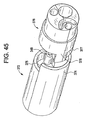
図19を参照して、光学デバイス200を説明する。光学デバイス200は、概して、可撓性シャフト202、ハンドル204、カメラアセンブリ206、およびオプションのアプリケータ部材208を含む。前述の実施形態と同様に、シャフト202は、ハンドル204とカメラアセンブリ206との間に延在し、略成形可能である。アプリケータ部材208は、シャフト202上のアプリケータ部材208の摺動移動を制限する、第1および第2の停止部210の間で、シャフト202に摺動可能に連結される。しかしながら、アプリケータ部材208は、含まれる場合、シャフト202に固定して連結されてもよく、または、アプリケータ部材は、摺動可能に連結されてもよく、停止部210は、省略されてもよいことを理解されたい。
The
アプリケータ部材208は、光学デバイス200で検査されている身体開口部を密封する、または塞ぐように、含まれてもよい。そのような密封は、例えば、子宮の検査中に、子宮が生理食塩水、CO2、または別の流体で拡張されてもよいように、所望されてもよい。アプリケータ部材208は、身体開口部を流体的に密閉するのに十分な、任意の柔軟な材料から構築されてもよい。例えば、アプリケータ部材208は、円錐または裁頭円錐形状を有し、かつ発泡体またはシリコーンから構築されてもよく、流体密封を向上するらせん溝212等の表面特徴を有するか、または平滑な外側面を有してもよい。
連結機能はまた、アプリケータ部材208がシャフト202に一時的に連結されてもよいように、シャフト202上に提供されてもよい。そのような一時的連結は、アプリケータ部材208が身体開口部に正確に配置されてもよいように、所望されてもよい。アプリケータ部材208が適切な位置へと回転されてもよいように、アプリケータ部材208がらせん溝を含む時に、該連結は特に有利であってもよい。
A coupling function may also be provided on the
さらなる実施形態では、外管がシャフト202の周囲に含まれてもよい。外管は、シャフト202に対して外管を摺動すると、シャフト202に沿って長手方向にアプリケータ208を移動させるように、アプリケータ208に連結されてもよい。好ましくは、外管は、シャフト202上で束ねられるか、またはシャフト202上でしわのない状態に伸展されてもよいように、構成される。例えば、外管は、圧搾可能部分を含んでもよい。圧搾可能部分は、外管がシャフト202に対して移動されてもよいように、圧縮された、部分的に圧縮された、または伸展された構成の自己係止である、蛇腹であってもよい。
In further embodiments, an outer tube may be included around the
さらに、アプリケータ208は、膨張式バルーンに置き換えられるか、またはそれに加えて使用されてもよいことを理解されたい。膨張式バルーンは、遠位端等において、シャフト202の外面に連結されてもよく、バルーンを膨張させて、開口部を密封する、または塞ぐ、あるいは空洞を拡張するために、生理食塩水またはCO2等の膨張流体が使用されてもよいように、膨張管腔がシャフトを通って提供されてもよい。
Further, it should be understood that the
上記のように、光学デバイスのための回路およびソフトウェアは、カメラアセンブリの一部として、および/またはハンドルに含まれてもよい。好ましくは、回路およびソフトウェアは、使い捨てシャフトとともに再利用されてもよいように、ハンドル内に提供されてもよい。回路は、ユーザに、カメラアセンブリを制御し、カメラアセンブリによって収集された画像データを操作する能力を提供する、埋め込みソフトウェアを好ましくは含む、制御器を含む。例えば、回路は、カメラヘッドの配向、焦点、および/またはズームの制御を提供してもよい。回路はまた、照明源によって提供される光の輝度および/または色の制御を提供してもよい。回路はまた、ユニバーサルシリアルバス(USB)構成要素を含んでもよいため、本発明の光学デバイスは、周辺デバイス、例えば、パーソナルコンピュータに容易に連結されてもよく、また、標準的な米国レコーディング会社(RCA)ケーブルまたは任意の他のケーブルを介した、全米テレビジョン放送方式標準化委員会(NTSC)モニタへの接続を含んでもよい。さらに、回路は、無線構成要素を含んで、光学デバイスと周辺デバイス(例えば、モニタおよび/または記録デバイス)との間の無線通信を提供してもよい。加えて、回路は、図1に示される出力コネクタが、モニタまたは他のビデオ画面に、または記録デバイスに直接接続されてもよいように、構成要素を含んでもよい。ハンドル内に提供される回路はまた、静止画像、ビデオ、および/または音声を記憶することが可能であってもよい。 As described above, circuitry and software for the optical device may be included as part of the camera assembly and / or in the handle. Preferably, circuitry and software may be provided in the handle so that it may be reused with a disposable shaft. The circuitry includes a controller, preferably including embedded software, that provides the user with the ability to control the camera assembly and manipulate the image data collected by the camera assembly. For example, the circuitry may provide control of camera head orientation, focus, and / or zoom. The circuit may also provide control of the brightness and / or color of the light provided by the illumination source. Since the circuit may also include a universal serial bus (USB) component, the optical device of the present invention may be easily coupled to a peripheral device, such as a personal computer, and a standard US recording company ( Connection to a National Television Broadcasting Standards Committee (NTSC) monitor may be included via an RCA) cable or any other cable. Further, the circuitry may include wireless components to provide wireless communication between the optical device and peripheral devices (eg, a monitor and / or recording device). In addition, the circuit may include components such that the output connector shown in FIG. 1 may be connected to a monitor or other video screen or directly to a recording device. The circuitry provided in the handle may also be capable of storing still images, video, and / or audio.
一実施形態では、小型ディスプレイ画面が、デバイスのハンドルに組み込まれる。別の実施形態では、ディスプレイがハンドルによって支持されるように、小型ディスプレイデバイスは、デバイスのハンドル上に提供されるコネクタに差し込まれる。 In one embodiment, a small display screen is incorporated into the handle of the device. In another embodiment, the small display device is plugged into a connector provided on the handle of the device so that the display is supported by the handle.
電力は、バッテリまたはハンドル回路に電気的に連結される外部電源によって、提供されてもよい。バッテリを利用する実施形態では、バッテリは、所望であれば、再充電可能であってもよく、回路は、ハンドル内にある間にバッテリが充電されてもよいように、提供されてもよい。例えば、回路に直接差し込む、電力アダプタが提供されてもよい。あるいは、誘導充電回路がハンドルに含まれてもよく、ハンドルをクレードルに挿入すると、バッテリを誘導的に充電するように、相補的クレードルが提供されてもよい。 The power may be provided by an external power source that is electrically coupled to a battery or handle circuit. In embodiments that utilize a battery, the battery may be rechargeable if desired, and circuitry may be provided so that the battery may be charged while in the handle. For example, a power adapter may be provided that plugs directly into the circuit. Alternatively, an inductive charging circuit may be included in the handle, and a complementary cradle may be provided to inductively charge the battery when the handle is inserted into the cradle.
光学デバイスが支持デバイスに一時的にクリップで留められてもよいように、クリップ部材もまた、光学デバイスのハンドル上に提供されてもよい。例えば、支持デバイスは、ユーザが保持する必要なく、光学デバイスが適切な位置で保持されてもよいように、患者に一時的に連結されてもよい(例えば、接着ストリップによって)。クリップ部材はまた、検鏡等の処置中に、光学デバイスを別の外科デバイスに連結することができるように、構成されてもよい。 A clip member may also be provided on the handle of the optical device so that the optical device may be temporarily clipped to the support device. For example, the support device may be temporarily coupled to the patient (eg, by an adhesive strip) so that the optical device may be held in place without the user having to hold it. The clip member may also be configured so that the optical device can be coupled to another surgical device during a procedure such as a speculum.
加えて、使用中に、シャフトの先端が、屈曲、指向、回転、および/または平行移動されてもよいように、機械的制御機器がハンドル上に提供されてもよい。例えば、カメラアセンブリに隣接するシャフトの端に、またはカメラアセンブリに直接結合される、スライドスイッチがハンドル上に含まれてもよい。結合は、スライドスイッチの操作により、シャフトが屈曲され、カメラアセンブリおよびカメラヘッドがシャフトに対して回転され、または、シャフトに対して屈折または屈曲すること等によって、カメラを移動させるように、構成されてもよい。カメラヘッドは、ゼロ角度位置から両方向性に0〜200度等、より大きい可動域にわたって回転またはヒンジ連結されてもよいことを理解されたい。好ましくは、制御機器は、カメラヘッドが+/−0〜30度の範囲にわたって回転されてもよいように、構成される。シャフトの長手方向軸に略平行な軸の周囲でシャフトに対して回転するヘッドを利用する、実施形態では、カメラヘッドは、下記でさらに詳細に記載されるように、0〜200度であるが、好ましくは160〜180度の間の範囲にわたって回転されてもよい。シャフトの成形可能性はまた、ユーザが、所望に応じて、カメラの配向を事前設定することも可能にすることを理解されたい。 In addition, a mechanical control device may be provided on the handle so that, in use, the tip of the shaft may be bent, oriented, rotated, and / or translated. For example, a slide switch may be included on the handle that is coupled to the end of the shaft adjacent to the camera assembly or directly to the camera assembly. The coupling is configured to move the camera by operating the slide switch, causing the shaft to bend, the camera assembly and camera head to rotate relative to the shaft, or to bend or bend relative to the shaft, etc. May be. It should be understood that the camera head may be rotated or hinged over a greater range of motion, such as 0-200 degrees in both directions from the zero angle position. Preferably, the control device is configured such that the camera head may be rotated over a range of +/− 0 to 30 degrees. In embodiments that utilize a head that rotates relative to the shaft about an axis that is substantially parallel to the longitudinal axis of the shaft, the camera head is between 0 and 200 degrees, as described in more detail below. , Preferably rotated over a range between 160 and 180 degrees. It should be understood that the moldability of the shaft also allows the user to preset the camera orientation as desired.
図20−24を参照して、シャフト222に垂直な軸に沿って、カメラアセンブリ226がシャフト222に対して回転されてもよいように、ヒンジ部材228によってシャフト222に連結されるカメラアセンブリ226を含む、光学デバイスの実施形態を説明する。前述の実施形態と同様に、シャフト222は、ハンドル(図示せず)とカメラアセンブリ226との間に延在する、本体部材223およびシャフト先端232を含む。細長い本体部材223は、略可撓性であり、好ましくは成形可能である。
20-24,
細長い本体部材223は、ハンドルに連結される第1の近位端と、オプションのシャフト先端232に連結される第2の遠位端230とを含む。細長い本体部材223は、図24に示されるように、複数の管腔を画定する。特に、細長い本体部材223は、流体導管234と、可撓性のプリント回路、例えば、可撓性の回路237およびワイヤを受容するための管腔236と、引張ワイヤ管腔238と、補強ワイヤ管腔240とを含む。細長い本体223は、好ましくは押出成形される。
The
流体導管234は、細長い本体部材223を通って長手方向に延在し、生理食塩水、CO2または任意の他の流体の標的部位への導入および/またはそこからの吸引を提供する。流体導管234は、細長い本体部材223の内部および細長い本体部材223の外壁を横断して延在する索条を形成する、第1の壁242によって画定される。
The
管腔236は、第1の壁242、第2の壁244、および細長い本体部材223の外壁によって画定される。第2の壁244は、第1の壁242に平行かつ離間され、また、細長い本体223の内部を横断して延在する索条を形成する。本実施形態の管腔236は、略長方形の断面形状を有する。管腔236のサイズおよび形状は、細長い本体部材223の全体的な断面積を低減しながら、可撓性のプリント回路237を受容するように選択される。
引張ワイヤ管腔238および補強ワイヤ管腔240は、第2の壁244と細長い本体部材223の外壁との間に形成される。特に、引張ワイヤ管腔238は、円筒形の管状部分247を含む、第2の壁244と細長い本体部材223の外壁との間に吊設された第3の壁246によって画定される。管状部分247は、細長い本体部材223を通って長手方向に延在する。引張ワイヤ管腔238は、図20−22に示されるように、ヒンジ部材228が作動されてもよいように(すなわち、カメラアセンブリ226がシャフト222に対して回転されてもよいように)、ハンドルとカメラアセンブリ226との間に延在する引張ワイヤ248を受容するように構成される。
補強ワイヤ管腔240は、引張ワイヤ管腔238に隣接する第3の壁246の両側に提供される。補強ワイヤ管腔240は、可撓性の細長い本体部材223の形状が操作されてもよいように、補強ワイヤを受容するために使用されてもよい。例えば、細長い本体部材223が補強ワイヤの形状をとるよう付勢されるように、屈曲構成を有する補強ワイヤが補強ワイヤ管腔240に挿入されてもよい。あるいは、その長さにわたって可変剛性を有する補強ワイヤが補強ワイヤ管腔240に挿入されて、細長い本体部材223に同じ可変剛性を付与してもよい。
Reinforcing
オプションのシャフト先端232は、シャフト222の遠位第2端230に連結される。シャフト先端232は、好ましくは、シャフト222に永久に連結される。シャフト先端232は、所望であれば、相互係止して円筒形のシャフト先端アセンブリ232を形成する、略半円筒形部材から組み立てられてもよいことを理解されたい。
シャフト先端232は、細長い本体223の管腔の一部または全体と連通する管腔を含む。例えば、シャフト先端232は、流体導管250、可撓性の回路237のための管腔252、および引張ワイヤ管腔254を画定するが、補強ワイヤ管腔240と連通する管腔を含まない。しかしながら、シャフト先端232は、所望であれば、補強ワイヤ管腔を含んでもよいことを理解されたい。
The
流体導管250は、シャフト先端232の一部を通って延在し、シャフト先端232の側壁を退出する。あるいは、流体導管250は、所望であれば、先端の遠位面に沿って退出するように、シャフト先端232を通って長手方向に延在してもよいことを理解されたい。
The
管腔252は、シャフト222の中心長手方向軸に概して沿って、シャフト先端232を通って長手方向に延在する。管腔252のサイズおよび形状は、可撓性のプリント回路237、および可撓性のプリント回路237とシャフト222の遠位端との間に延在するワイヤを受容するように選択される。
引張ワイヤ管腔254は、シャフト先端232を通って長手方向に延在し、引張ワイヤがシャフト222を通ってカメラアセンブリ226の中へ延在する経路を提供する。引張ワイヤ管腔254は、引張ワイヤ248が、シャフト222内で摺動可能であり、カメラアセンブリ226上に含まれる引張ワイヤ搭載機能258と整合するように、サイズ決定および配向される。本実施形態では、引張ワイヤ搭載機能258は、面取り表面260からカメラアセンブリ226の中へ延在する非貫通穴であり、引張ワイヤ248の遠位端は、非貫通穴の中で機械的に結合される。例えば、引張ワイヤ248の遠位先端は、穴の中で糊付けされてもよい。
The
複数の先端部材から組み立てられたシャフト先端を利用する実施形態では、管腔のうちのいずれも、先端部材の組み合わせによって画定されてもよい。例えば、先端部材のそれぞれは、管腔252の一部を画定する、略U字形または半円筒形チャネルを含む。先端部材がシャフト先端232に組み立てられると、チャネルが整合して管腔252を形成する。さらに、所望であれば、シャフト先端232は省略されてもよいことを理解されたい。例えば、細長い本体部材の遠位端は、収縮包装されるか、あるいは、別個のシャフト先端を採用せずに密封されてもよい。そのような実施形態では、細長い本体部材を通って延在する流体導管は、細長い本体部材の遠位端における、またはそれに隣接する退出口を含んでもよい。
In embodiments that utilize a shaft tip assembled from multiple tip members, any of the lumens may be defined by a combination of tip members. For example, each of the tip members includes a generally U-shaped or semi-cylindrical channel that defines a portion of
カメラアセンブリ226が、シャフト222に対して屈曲または回転されてもよいように、カメラアセンブリ226は、ヒンジ部材228を介してシャフト222に連結される。カメラアセンブリの構造は、上記のカメラアセンブリと実質的に同一である。しかしながら、カメラ筐体256は、カメラアセンブリ226とシャフト222との間の付加的な相対運動を提供するように改良されている。特に、カメラ筐体256の近位端(すなわち、シャフト222に最も近いカメラ筐体の端)は、カメラアセンブリ226とシャフト222との間で得られる相対運動が増加されるように、面取り表面260を含む。
The
ヒンジ部材228は、可撓性の回路237のヒンジ部分262から構築される。可撓性の回路237のヒンジ部分262は、シャフト222とカメラアセンブリ226との間を延在し、シャフト222とカメラアセンブリ226との間の相対運動を可能にする。1対の保護シート264は、ヒンジ部分262を挟入する。本実施形態では、保護シート264は、可撓性の回路237で挟まれるが、それらは直接互いに取り付けられない。
The
示されるように、保護シート264およびヒンジ部分262は、防水収縮包装に封入されてもよい。収縮包装266の端は、シャフト222およびカメラアセンブリ226の中へ延在し、その中で連結されて液体密封を提供する。収縮包装266とシャフト222およびカメラアセンブリ226のそれぞれとの間の液体密封は、可撓性の回路237が流体の進入から保護されることを確実にする。
As shown, the
引張ワイヤ248は、ヒンジ部材228の屈曲のユーザ制御を提供する。本実施形態では、ヒンジ部材228は、可撓性の回路237の形状により、単一軸に沿って屈曲するように偏向される。特に、可撓性の回路237のヒンジ部分262は、高さを超える幅を伴う、略長方形の断面を有する。結果として、ヒンジ部材228は、可撓性の回路237の幅寸法と平行な軸に沿って屈曲するように偏向される。ヒンジ部材228は、単一軸に沿って屈曲するように偏向されるため、単一引張ワイヤ248が採用されてもよい。引張ワイヤ248は、ユーザが引張ワイヤ248に張力を印加すると、カメラアセンブリ226の一側面をシャフト222に向かって引くことにより、ヒンジ部材228を屈曲させるように、構成される。
Pull
加えて、ヒンジ部材228は、可動域内の特定位置へ偏向するように構築されてもよい。例えば、ヒンジ部材228は、ヒンジ部材228に屈曲がなく、カメラアセンブリ226の光軸がシャフト222の長手方向軸と略整合する(本明細書では、「ゼロ角度位置」と呼ばれる)ように、偏向されてもよい。あるいは、ヒンジ部材228は、屈曲位置へ偏向されてもよい。引張ワイヤ248の張力は、カメラアセンブリが可動域内の任意の位置へ設定されるように、調整可能であってもよい。例えば、ヒンジ部材228の偏向は、ヒンジ部材228が第1の回転位置へ自然に屈曲されるように構成されてもよい。引張ワイヤ248の張力は、ヒンジ部材がゼロ角度位置に戻されるように、調整されるか、または初期設定されてもよい。次いで、ヒンジ部材228は、引張ワイヤへの張力をさらに増加させることによって、第2の回転位置へ屈曲されてもよい。結果として、ゼロ角度位置の両方の位置へ屈曲することが可能なカメラアセンブリ226を提供しながら、単一引張ワイヤ248を使用し、一定の張力に維持してもよい。
In addition, the
引張ワイヤ248はまた、張力および圧縮の両方がカメラアセンブリ226に伝達されるように半剛性となるように、構成されてもよい。そのような実施形態では、ヒンジ部材228は、ゼロ角度位置へ偏向されてもよく、次いで、引張ワイヤ248を押すと、カメラアセンブリ226を第1の回転位置に配置し、引張ワイヤ248を引くと、カメラアセンブリ226を第2の回転位置に配置し、第1および第2の回転位置は、回転の反対方向に対応する。
The
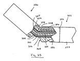
図25を参照すると、シャフト先端232は、面取り遠位表面268を含んでもよい。面取り遠位表面268は、シャフト222に対するカメラアセンブリ226のより大きい回転角を提供する。特に、シャフト222に対するカメラアセンブリ226のより大きい角度移動にわたって、カメラアセンブリ226とシャフト222との間の干渉が回避される。面取り表面260および268は、所望の任意の面取り角を有してもよいことを理解されたい。
With reference to FIG. 25, the
図26−29を参照して、シャフトとカメラアセンブリとの間のヒンジ部材の別の実施形態を含む、光学デバイスの別の実施形態の遠位端を説明する。特に、ヒンジ部材270は、カメラアセンブリが光学デバイスのシャフト274に対して選択的に回転されてもよいように、カメラアセンブリのカメラ筐体271をシャフト先端272に連結する。前述の実施形態と同様に、シャフト274は、ハンドル(図示せず)とカメラアセンブリのカメラ筐体271との間に延在する、細長い本体部材273およびシャフト先端272を含む。細長い本体部材273は、略可撓性であり、好ましくは成形可能である。
With reference to FIGS. 26-29, the distal end of another embodiment of an optical device will be described, including another embodiment of a hinge member between the shaft and the camera assembly. In particular, the
ヒンジ部材270は、シャフト先端272をカメラ筐体271と移動可能に連結し、カメラ筐体271の近位端から近位に延在する円筒形突起275、およびシャフト先端272の遠位端に含まれる円筒形ポケット276から概して形成される。本実施形態では、円筒形突起275およびポケット276は、それぞれがシャフト274の長手方向軸に垂直な長手方向軸を有するように配向される。結果として、円筒形突起275が円筒形ポケット276に受容されると、カメラ筐体271が同様にシャフト274の長手方向軸に垂直な軸に沿ってシャフト274に対して回転することを可能にする、移動可能な接合部を形成する。
A
前述の実施形態と同様に、カメラアセンブリがシャフト274および/またはハンドルに含まれる電子機器に電気的に連結されるように、ヒンジ部材270に広がる可撓性のプリント回路が提供されてもよい。シャフト先端272は、交差し、円筒形ポケット276内への開口部を含む、管腔277を含む。カメラ筐体271は、円筒形突起275を通って延在し、また円筒形ポケット276へと開いた管腔278を含む。管腔278の近位端は、ヒンジ部材270が作動されると、段階的屈曲が管腔277および278を通って延在する可撓性のプリント回路に付与されるように、先細開口部279を含む。
Similar to the previous embodiment, a flexible printed circuit extending to the
ヒンジ部材270は、引張ワイヤ管腔281を通ってカメラ筐体271の中へ延在する、引張ワイヤによって作動されてもよい。実施形態では、引張ワイヤは、シャフト274に対して選択的に前進および/または後退されてもよいように、管腔281の中で摺動可能に受容される。引張ワイヤの遠位端は、非貫通穴であってもよく、示されるように、非線形であってもよい、引張ワイヤ搭載機能282においてカメラ筐体271に連結される。引張ワイヤ管腔281の遠位端および引張ワイヤ搭載機能282の近位端は、ヒンジ部材270が作動されると、段階的屈曲が引張ワイヤに付与されるように、先細開口部を含んでもよい。
The
本実施形態では、ヒンジ部材270の回転軸は、垂直であり、シャフト先端272およびカメラ筐体271の長手方向軸から離間される。ヒンジ部材270の回転軸の場所は、任意の所望の位置に位置して、シャフト274を通って延在する1つ以上の流体導管および/または1つ以上のワーキングチャネル等のチャネルの所望の量の回転または隙間を提供する。
In the present embodiment, the rotation axis of the
加えて、本実施形態では、シャフト先端272およびカメラ筐体271は、それぞれ複数の相補的構成要素から構築される。シャフト先端272は、円筒形ポケット276に交差する嵌合接合面を有する構成要素を含む。その構成は、シャフト先端272が円筒形突起275上で組み立てられることを可能にすることによって、組み立てを単純化する。その上、多重部品構成はまた、シャフト先端272およびカメラ筐体271の両方が、可撓性のプリント回路上で組み立てられることも可能にする。カメラ筐体271およびシャフト先端272の構成要素はまた、整合タブ283および整合タブソケット284等の整合機能を含んで、組み立てをさらに単純化してもよい。
In addition, in this embodiment, the
円筒形突起275および円筒形ポケット276の場所は、逆転されてもよいことを理解されたい。例えば、円筒形突起275は、シャフト先端272から延在してもよく、円筒形ポケット276は、カメラ筐体271に含まれてもよい。
It should be understood that the location of the
シャフト先端272の遠位表面および/またはカメラ筐体271の近位表面はまた、面取りを含んでヒンジ部材270の得られる回転を増加させてもよい。特に、面取りは、カメラ筐体271が、ヒンジ部材270の回転移動の終了時にシャフト先端272に接触しないように、隙間を提供する。
The distal surface of
図30および31に示される、別の実施形態では、ヒンジ部材285は、円筒形突起286、円筒形ポケット287、およびヒンジ心棒288を含む。円筒形突起286は、円筒形ポケット287の中へ延在し、ヒンジ心棒288は、円筒形突起を通ってシャフト先端289の側壁の中へ横方向に延在することにより、円筒形突起286を円筒形ポケット287内に保持する。ヒンジ心棒288は、円筒形突起286が円筒形ポケット287内で回転することが可能となるように、円筒形突起286またはシャフト先端289の一方または他方に固定して連結されてもよい。あるいは、ヒンジ心棒288は、シャフト先端289および円筒形突起286の両方に対して自由に回転可能であってもよい。
In another embodiment, shown in FIGS. 30 and 31, the
円筒形突起286と円筒形ポケット287との間の回転接合面を横断して、円筒形突起286およびシャフト先端289を通って延在する、管腔290が含まれる。管腔290は、カメラ筐体291がシャフト先端289に対して回転されると、段階的屈曲が管腔290を通って延在する可撓性のプリント回路に付与されるように、先細部分を含んでもよい。
A lumen 290 is included that extends through the
本実施形態では、シャフト先端289に対するカメラ筐体291の回転軸は、シャフト先端289の中心長手方向軸に交差するように配置されるが、回転軸は、シャフト先端289の中心長手方向軸に対して任意の半径方向位置に位置してもよいことを理解されたい。加えて、円筒形ポケット287は、先細開口部が提供されて、カメラ筐体291とシャフト先端289との間の所望の量の相対的回転を可能にする。円筒形ポケット287の先細開口部は、円筒形突起が、円筒形突起286の円筒形表面から略接線方向に延在する、平行側壁を含むことを可能にする。ヒンジ部材285は、引張ワイヤ管腔292を通って延在し、カメラ筐体291に連結される、引張ワイヤ(図示せず)によって作動されるように構成される。
In this embodiment, the rotation axis of the
円筒形ヒンジ構成は、可撓性のプリント回路が、移動範囲の全体を通して、カメラ筐体およびシャフトシャフトの内側で保護されたままである、ヒンジ部材を提供する。加えて、該構成は、収縮包装等の保護シートまたは保護被覆を含む必要性をあらかじめ避ける。 The cylindrical hinge configuration provides a hinge member where the flexible printed circuit remains protected inside the camera housing and shaft shaft throughout the range of travel. In addition, the configuration avoids in advance the need to include a protective sheet or protective coating such as shrink wrap.
可撓性のプリント回路237は、好ましくは、その寸法がその長さにわたって変化するように構築される。例えば、図32Aに示されるように、可撓性のプリント回路237は、第2の部分299よりも小さい横寸法を有する、可撓性のプリント回路237の第1の部分298の端において、カメラヘッド297に連結される。ヒンジ部分262(例えば、図25)は、ヒンジ部分が第2の部分299よりも小さい横寸法を有するように、第1の部分298に含まれる。可撓性のプリント回路237の形状は、可撓性のプリント回路237上の電子回路に対する十分な空間を可能にしながら、薄いヒンジ部分262を提供する。
The flexible printed
図32Bおよび32Cは、本発明による、光学デバイス内に含むための可撓性のプリント回路293の別の実施形態の斜視図である。図32Bに示されるように、可撓性のプリント回路293は、より薄い可撓性部分293a、ならびに、折り畳み領域293eおよび293fによって分離される、より幅が広い可撓性の回路部分293b、293c、および293dを含む。可撓性の回路部分293b、293c、および293dのうちの1つ以上(例えば、293bおよび293c)は、回路構成要素293gを含んでもよいが、部分293b−dの他の1つ以上(例えば、293d)は、そうでなくてもよい。一部の実施形態では、可撓性の回路部分293b、293c、および293dのそれぞれは、同じ長さを有してもよい。一部の実施形態では、可撓性のプリント回路293は、光学デバイスのシャフト内に長手方向に挿入されてもよい。他の実施形態では、図32Cに示されるように、可撓性のプリント回路293は、デバイス(例えば、光学デバイス以外のデバイス)への挿入の前に、2つの折り畳み領域において180度に折り畳まれ、したがってその長さを低減してもよい。薄い可撓性部分293aは、可撓性のプリント回路293の長さをさらに低減するために、折り畳まれるか、あるいは束ねられてもよい。
32B and 32C are perspective views of another embodiment of a flexible printed
本発明の光学デバイスはまた、カメラアセンブリが光学デバイスの長手方向軸から半径方向外向きに移動されてもよいように、機械的制御機器を含んでもよい。そのような機能は、ワーキングチャネルへのアクセスを提供しながら、挿入中のデバイスの寸法を最小限化するために使用されてもよい。前述のように、光学デバイスを通って標的部位への経路を提供するようにワーキングチャネルが組み込まれてもよい。カメラアセンブリおよびワーキングチャネルの並列構成を利用する実施形態では、光学デバイスの全体的な外側寸法を増加させなければならない。しかしながら、デバイスは、代替として、挿入中のみにワーキングチャネルを遮断する、移動可能カメラアセンブリを含んでもよい。 The optical device of the present invention may also include mechanical control equipment such that the camera assembly may be moved radially outward from the longitudinal axis of the optical device. Such a feature may be used to minimize the size of the device during insertion while providing access to the working channel. As described above, a working channel may be incorporated to provide a path through the optical device to the target site. In embodiments that utilize a parallel configuration of the camera assembly and working channel, the overall outer dimensions of the optical device must be increased. However, the device may alternatively include a movable camera assembly that blocks the working channel only during insertion.
半径方向外向きに移動されてもよいカメラアセンブリを含む、光学デバイスの実施形態を、図33−42を参照して説明する。まず図33を参照すると、光学デバイス300は、概して、シャフト302、ハンドル(図示せず)、およびカメラアセンブリ306を含む。
An embodiment of an optical device that includes a camera assembly that may be moved radially outward will be described with reference to FIGS. 33-42. Referring first to FIG. 33, the
シャフト302は、ハンドルとカメラアセンブリ306との間に延在し、可撓性かつ成形可能である。前述の実施形態と同様に、シャフトは、細長い本体330および先端332を含み、シャフト302の第1端は、ハンドルの端に移動可能に連結される。シャフト302は、シャフト302およびカメラアセンブリ306の廃棄およびハンドルの再利用を可能にするように着脱可能である。
The
本実施形態では、カメラアセンブリ306は、シャフト302の長手方向軸と平行で離間した軸の周囲で、シャフト302に対して回転されてもよいように構成される。相対的回転は、光学デバイス300が、図33に示される第1の構成と、図34および35に示される、カメラアセンブリ306がシャフト302の長手方向軸から半径方向外向きに移動される第2の構成との間で、転換されることを可能にする。
In this embodiment, the
第1の構成では、光学デバイス300の遠位端の外部寸法は、体腔への挿入を単純化するように最小限化される。そのような構成では、カメラアセンブリ306の長手方向軸は、シャフト302の長手方向軸と略一致する。
In the first configuration, the external dimensions of the distal end of
第2の構成では、カメラアセンブリ306の長手方向軸がシャフト302の長手方向軸から相殺されるように、カメラアセンブリ306は、シャフト302に対して回転される。図35に示されるように、第2の構成へのカメラアセンブリ306の回転は、ワーキングチャネル310の遠位開口部308ならびに流体導管314の出口312に対する隙間を提供する。
In the second configuration, the
カメラアセンブリ306は、シャフト302および/またはハンドルに内蔵される処理回路に電気的に連結される、カメラヘッド316を含む。カメラヘッド316は、光学部品318および光源320を含み、カメラ筐体アセンブリ322によって封入される。
図35および36を参照すると、カメラ筐体アセンブリ322は、ともに連結されて、少なくとも部分的にカメラヘッド316を封入する、2つの筐体部材323および324を含む。本実施形態では、筐体部材323、324のそれぞれは、半円筒形である。筐体部材323、324は、組み合わされて、カメラヘッドを受容し、少なくとも部分的に封入するように構成される、空洞356を画定する。筐体部材323、324はまた、組み合わされて、可撓性の回路等の回路がカメラヘッドとシャフト302との間を通るようにチャネルを提供する、開口360も画定する。最終的に、筐体部材323、324は、組み合わされて、ヒンジピン開口358等のヒンジピン搭載機能を画定する。下記でさらに詳細に論じられるように、ヒンジピン開口358は、ヒンジピン348の遠位端を受容し、それに固定して連結される。ヒンジピン348は、シャフト302の少なくとも一部を通ってカメラ筐体アセンブリ322の中へ延在し、シャフト302に対するヒンジピン348の回転が、筐体アセンブリ322および封入されたカメラヘッドをシャフト302に対して回転させることにより、光学デバイスを第2の回転構成に配置するように、シャフト302内で回転可能である。
With reference to FIGS. 35 and 36, the
筐体部材324は、筐体部材324の近位端から延在する、オプションの位置付けおよび移動制限ピン326を含む。位置付けピン326は、位置付けピン326の最遠近位端上に配置されるヘッド328を含む、細長い部材である。ヘッド328は、拡大された外径を含む、位置付けピン326の一部である。ヘッド328は、シャフト先端アセンブリ332の一部に係合して、シャフト302の長手方向軸の方向でのシャフト302とカメラアセンブリ306との間の相対的平行移動を防ぐ一方で、カメラアセンブリ306が所定の回転移動にわたってシャフト302に対して回転することを可能にする。
The
位置決めピン326およびヘッド328は、図35および37−40に示されるシャフト先端アセンブリ332の機能に係合する。シャフト先端アセンブリ332は、所望であれば、複数のシャフト先端部材から構築されてもよく、または、単体として成形されてもよい。先端アセンブリ332は、シャフト302の遠位端に固定して連結される。先端アセンブリ332は、少なくとも1つの流体導管350、ヒンジピン管腔354、ワーキングチャネル350(本明細書では「アクセスチャネル」とも呼ばれる)、および可撓性のプリント回路またはワイヤの一部を受容するように構成される管腔352を含み、その全ては、先端アセンブリ332の近位部分を通って延在し、アセンブリの座ぐり穴があいた遠位部分において終端する。本実施形態では、管腔のそれぞれは、先端アセンブリ332の近位部分のみを通って延在して示されるものの、先端アセンブリは、座ぐり穴があいた遠位部分を含む必要がなく、管腔は、先端アセンブリ332を完全に通って延在してもよいことを理解されたい。
Locating
隆起362は、先端アセンブリ332の座ぐり穴があいた遠位部分に含まれる。隆起362は、ヒンジピン管腔354と略同心円状の外面364を画定する。組み立てられた光学デバイスでは、筐体部材324に含まれる位置付けピン326の外面は、カメラアセンブリ306とシャフト302との間の相対移動中に外面364に沿って摺動する。
The
隆起362は、先端アセンブリ332の遠位端から、管腔352の遠位端から離間される場所へと近位に延在する。加えて、管腔352は、略三日月形またはC字形であり、ヒンジピン管腔354と同心円状である、より小さい直径の弓形内面366と、より大きい直径の弓形内面368とを含む。ヒンジピン管腔354の長手方向軸と表面366との間の半径方向距離は、隆起が段部370を形成するように、ヒンジピン管腔354の長手方向軸と隆起362の外面364との間の半径方向距離よりも小さい。段部370は、ヘッド328と接合面を成して、シャフト302の長手方向軸の方向での先端アセンブリ332とカメラアセンブリ306との間の相対的平行移動を制限する。
The
同時に、ヒンジピン管腔354の長手方向軸と表面366との間の半径方向距離は、可撓性のプリント回路が、管腔352から、隆起362を通り越えてカメラアセンブリ306の中へ容易に延在してもよいように、ヒンジピン管腔354の長手方向軸と外面364との間の半径方向距離よりも大きい。
At the same time, the radial distance between the longitudinal axis of the
シャフト302は、先端アセンブリ332の管腔と整合し、連通する管腔(例えば、管腔310および管腔312)を含む。シャフト302はまた、シャフト302を通って半径方向に延在する一部を含み、シャフト302の側面に開口部を含む、流体導管334等の付加的な管腔を含んでもよい。好ましくは、流体導管351は、注入ポートとして構成され、流体導管334は、生理食塩水等の流体が、注入ポートと排出ポートとの間でカメラアセンブリ306を越えて流れることを強いられるように、排出口として構成される。そのような構成は、生理食塩水または別の流体の使用を単純化してカメラアセンブリ306のレンズを残屑のない状態に保つために、使用されてもよい。加えて、排出に使用される流体導管はまた、光学デバイスが第1の構成である時に、光学デバイスが取り外される前に生理食塩水または残屑が排出されてもよいように、好ましくは、シャフト302の側面から退出する。
図41および42を参照して、カメラアセンブリ306とシャフト302との間の相対的回転を説明する。図41に示される第1の整合構成では、カメラアセンブリ306(透視で示される)は、シャフト302と同心円状に整合している。その構成では、位置付けピン326は、隆起362の外面364に沿って第1の位置に位置し、可撓性のプリント回路337は、位置付けピン326に隣接して配置される。
41 and 42, the relative rotation between
可撓性のプリント回路337は、先端アセンブリ332およびカメラアセンブリ306のそれぞれに密封されてもよく、密封場所間で延在する部分は、カメラアセンブリ306の自由な回転のための弛緩がないようにサイズ決定されてもよい。可撓性のプリント回路の弛緩部分は、光学デバイスが第1の挿入構成である時に、先端アセンブリ332の座ぐり穴があいた部分内に位置してもよい。可撓性のプリント回路は、所望であれば、収縮包装に内蔵されてもよいことを理解されたい。その上、所望の可撓性が提供されてもよいように、可撓性のプリント回路の緩い部分とともに、補強材が使用されてもよく、または使用されなくてもよい。
The flexible printed
図42に示される第2の回転構成では、カメラアセンブリ306は、ヒンジピン348の周囲でシャフト302に対して回転される。回転構成では、位置付けピン326は、隆起362の外面364に沿って第2の位置へカメラアセンブリ306とともに回転している。本実施形態では、可撓性のプリント回路337の一部もまた、回転中に位置付けピン326に略隣接したままとなるように、カメラアセンブリ306とともに回転する。本実施形態では、カメラアセンブリ306から伝達される画像は、ユーザによって視認される画像が所望に応じたままとなるように、操作されてもよい。例えば、画像は、カメラアセンブリ306の物理的回転に対抗するように回転されてもよい。
In the second rotational configuration shown in FIG. 42, the
ヒンジピン348は、カメラアセンブリ306に固定して連結され、ヒンジピン管腔354内で自由に回転することができる。一部の実施形態では、ヒンジピン348は、(例えば、ハンドル筐体を通って)シャフト302の近位端へと直接延在しなくてもよいが、むしろ、遠位先端324において、かつハンドル中の制御機器(例えば、ノブ)内の他方の端上に固着される、細いワイヤに通過してもよい。制御機器を回転させると、ワイヤを旋回させてもよく、それは順に、遠位先端324を旋回させてもよい。他の実施形態では、ヒンジピン348は、ユーザによってヒンジピン管腔354内で容易に回転されて、カメラアセンブリ306を回転してもよいように、(例えば、ハンドル筐体を通って)少なくともシャフト302の近位端へと延在してもよい。ダイヤル、ノブ、または他の制御部材は、ハンドル筐体に取り付けられるか、またはシャフト302の側壁を通って延在する、ヒンジピン348に連結されてもよいため、ヒンジピンは、シャフト302に対して容易に回転されてもよい。
The
図43−45を参照して、カメラ筐体アセンブリおよびシャフト先端アセンブリの実施形態とともに光学デバイス300を図示する。特に、カメラ筐体アセンブリ372は、その近位端において円周段差374を含む。シャフト先端アセンブリ376は、相補的円周段差378を含む。図43に示されるように、光学デバイス300が第1の構成である時、段差374および段差378は、光学デバイス300の外面が連続するように、相互係止する。しかしながら、光学デバイス300が第2の構成である時、すなわち、カメラアセンブリがシャフトの長手方向軸から半径方向外向きに移動されると、段差は、互いから離れて回転される。
43-45, the
相互係止段差374および378は、シャフトに対するカメラアセンブリの回転移動に対する制限停止部を提供するために使用されてもよい。特に、第1の構成の方向でのシャフトに対するカメラアセンブリの移動は、図43に示されるように、段差374の嵌合表面375と段差378の嵌合表面379との間の接触によって制限される。第2の構成の方向でのシャフトに対するカメラアセンブリの移動は、図45に示されるように、段差374の第2の嵌合表面377とシャフト先端アセンブリ376の外面との間の接触によって制限される。
Interlocking steps 374 and 378 may be used to provide a limited stop for rotational movement of the camera assembly relative to the shaft. In particular, the movement of the camera assembly relative to the shaft in the direction of the first configuration is limited by contact between the
相補的円周段差を含むことの利点は、可撓性のプリント回路に付加的な応力を印加せずに、シャフトに対するカメラアセンブリの移動が制御されてもよいことである。別の利点は、光学デバイス300の第1の構成における嵌合表面間の接触であり、嵌合表面とシャフトの外面との間の接触は、カメラアセンブリが移動の終了まで回転されると、ユーザに触覚フィードバックを提供する。
An advantage of including a complementary circumferential step is that the movement of the camera assembly relative to the shaft may be controlled without applying additional stress to the flexible printed circuit. Another advantage is the contact between the mating surfaces in the first configuration of the
光学デバイスのシャフトは、流体導管、ワーキングチャネル、補強材管腔、および回路またはワイヤを受容するように構成される管腔の任意の所望の組み合わせおよび配向を提供する、任意の所望の構成を有してもよい。シャフトの細長い本体の種々の模範的実施形態を図46−49に図示する。シャフトの全ては概して、先端アセンブリの管腔と連通し、かつ整合する管腔を含む。 The shaft of the optical device has any desired configuration that provides any desired combination and orientation of fluid conduits, working channels, stiffener lumens, and lumens configured to receive circuits or wires. May be. Various exemplary embodiments of the elongated body of the shaft are illustrated in FIGS. 46-49. All of the shafts generally include a lumen in communication with and in alignment with the lumen of the tip assembly.
図46に示されるように、シャフト302は、先端アセンブリ332の管腔と連通し、かつ整合する管腔を含む。上記のように、シャフト302は、ワーキングチャネル310、流体導管334および312、可撓性のプリント回路のための管腔352、およびヒンジピン管腔354を含む。
As shown in FIG. 46, the
シャフトは、種々の使用に対して構成される、付加的な管腔を含んでもよい。例えば、シャフトは、1つ以上の付加的な流体導管および/または補強材管腔等の付加的な管腔を含んでもよい。図47を参照すると、シャフト382は、ヒンジピン管腔383、流体導管384および385、ワーキングチャネル386、可撓性のプリント回路381のための管腔387、および補強材管腔388を含む。本実施形態では、流体導管384および385は、ワーキングチャネル386の反対側に隣接し、かつその上に配置される。加えて、補強材管腔388は、長方形であり、ワーキングチャネル386と管腔387との間に配置される。
The shaft may include additional lumens configured for various uses. For example, the shaft may include one or more additional fluid conduits and / or additional lumens, such as reinforcement lumens. Referring to FIG. 47, the
図48を参照すると、シャフト392は、ヒンジピン管腔393、流体導管394および395、ワーキングチャネル396、可撓性のプリント回路391のための管腔397、ならびに補強材管腔398および399を含む。流体導管394および395は、ワーキングチャネル396の反対側に隣接し、かつその上に配置され、補強材管腔398および399は、各流体導管394、395に隣接して配置される。
Referring to FIG. 48, shaft 392 includes hinge pin lumen 393,
別の実施形態であるシャフト402を図49に図示する。シャフト402は、ヒンジピン管腔403、流体導管404および405、ワーキングチャネル406、可撓性のプリント回路401に対する管腔407、ならびに補強材管腔408および409を含む。任意の数および種類の管腔が含まれてもよく、管腔は、任意の所望の形状であってもよいことを理解されたい。さらに、可撓性のプリント回路に対する管腔は、可撓性のプリント回路がカメラアセンブリ306とともにシャフトに対して回転する必要がないように構成されてもよいことを理解されたい。その代わり、カメラアセンブリ306がシャフトに対して回転することを可能にする、可撓性ヒンジ部分が可撓性のプリント回路上に含まれてもよい。さらに他の実施形態では、同時に流体導管(例えば、生理食塩水チャネル)として機能することが可能なワーキングチャネルを含む、シャフトが提供されてもよい。この二重機能を促進するために、シャフトには、非円形(例えば、正方形、長方形、または楕円形)断面が提供されてもよい。チャネルの少なくとも1つの角は、非円形に画定されてもよい。したがって、器具がワーキングチャネルに挿入されると、ワーキングチャネルの角はなおも閉塞されず、したがって、流体の同時の流れを可能にする。
Another
図50および51を参照して、移動可能カメラアセンブリを含む光学デバイスの別の実施形態を図示する。光学デバイス420は、シャフト422の遠位端に移動可能に連結される、カメラアセンブリ426を含む。
With reference to FIGS. 50 and 51, another embodiment of an optical device including a movable camera assembly is illustrated.
カメラアセンブリ426は、カメラアセンブリ426がシャフト422に対して遠位に前進されるにつれて、シャフト422の遠位端に沿って摺動するように構成される、斜面427を含む。カメラアセンブリ426は、カメラアセンブリ426から、光学デバイスのユーザによって制御されるシャフト422を通って延在する、押込/引張ワイヤ(図示せず)を使用して、前進されてもよい。カメラアセンブリ426が前進されるにつれて、シャフト422の長手方向軸から半径方向外向きにカメラアセンブリ426を押し進めるために、1つ以上のバネ部材(図示せず)を使用してもよい。逆に、カメラアセンブリ426が後退されるにつれて、斜面427とシャフト422の縁との間の接合面は、バネ部材の力に対して、シャフト422の長手方向軸に向かって半径方向内向きにカメラアセンブリ426を移動させる。カメラアセンブリ配向が一定のままであるため、カメラアセンブリは、伝達された画像の操作を必要とせずに、使用のあらゆる段階を通して使用されてもよい。
バネ部材は、任意の種類のバネ、例えば、コイルバネまたは板バネであってもよい。一実施形態では、バネ部材は、伸展されるとフープを形成し、圧縮されると平坦となる1対の板バネである。そのような実施形態では、バネ部材は、バネ部材がワーキングチャネル425を妨げないように、フープが光学デバイス420を通って延在するワーキングチャネル425の直径よりも大きくなるように、選択される。
The spring member may be any type of spring, for example, a coil spring or a leaf spring. In one embodiment, the spring members are a pair of leaf springs that form a hoop when extended and become flat when compressed. In such embodiments, the spring member is selected such that the hoop is larger than the diameter of the working
図52および53を参照して、光学デバイス430を説明する。前述の実施形態と同様に、光学デバイス430は、シャフト431の遠位端に移動可能に搭載される、カメラアセンブリ432を含む。本実施形態では、カメラアセンブリ432は、シャフト431の長手方向軸に垂直な軸に沿って、カメラアセンブリ432がシャフト431に対して回転されるように、シャフト431とヒンジ連結される。結果として、光学デバイス430の挿入中に、カメラアセンブリ432の光軸は、前進の方向に対して角を成す。カメラアセンブリ432は、押込/引張ワイヤまたはケーブル、または任意の他の制御機構を使用して回転されてもよい。
With reference to FIGS. 52 and 53, the
移動可能カメラアセンブリを有する光学デバイスのさらなる代替的実施形態を図54および55に図示する。光学デバイス435は、カメラアセンブリ439がシャフト436に対して遠位に前進されるにつれて、シャフト436の長手方向軸から半径方向内向きに平行移動するように、シャフト436に移動可能に連結されるカメラアセンブリ439を含む。カメラアセンブリ439の運動は、シャフト436の内側または外側に埋め込まれてもよい、1つ以上のレール437によって制限される。カメラアセンブリ439は、レール437によって画定される所定の経路に沿ってアームが移動するように、レール437に係合する少なくとも1つのアーム438を含む。シャフト436に対してカメラアセンブリ439を移動させるために、押込/引張ワイヤまたはケーブル、または任意の他の制御機構が利用されてもよい。
A further alternative embodiment of an optical device having a movable camera assembly is illustrated in FIGS. The
移動可能カメラアセンブリを有する光学デバイスのなおもさらなる代替的実施形態を図56および57に図示する。光学デバイス440は、シャフト部材441と、シャフト部材441を摺動可能に受容する管腔を画定する細長いチューブ443とを含む。
A still further alternative embodiment of an optical device having a movable camera assembly is illustrated in FIGS. The
シャフト部材441は、シャフト部材441の遠位端から近位に延在する、少なくとも1つの長手方向スリットを含む。長手方向スリット444により、シャフト部材441の遠位部分は、チューブ443の遠位端外へ前進させられると、半径方向外向きに広がるように構成される、弁445に分割される。
The shaft member 441 includes at least one longitudinal slit that extends proximally from the distal end of the shaft member 441. The
本実施形態では、少なくとも1つのカメラアセンブリ446は、光学デバイス440に含まれ、弁445が閉鎖位置にある時に、カメラアセンブリ446がシャフト部材441内で部分的に隠されるように、弁445の内面に連結される。任意の数の長手方向スリット444およびカメラアセンブリ446が提供されてもよいことを理解されたい。例えば、別の実施形態では、1対の長手方向スリット444が提供されることにより、4つの弁445を画定し、カメラアセンブリ446が各弁上に提供される。そのような実施形態では、カメラアセンブリ446は、弁445が閉鎖構成である時に、カメラアセンブリ446が互いに対して長手方向に略整合するように、弁445上に配置されてもよい。一実施形態では、第1の弁445に配置される第1のカメラアセンブリ446は、最遠位に位置し、第2の弁445上に配置される第2のカメラアセンブリ446は、第1のカメラアセンブリの近位に位置する。第3の弁445上に位置する第3のカメラアセンブリ446は、第2のカメラアセンブリの最近位に位置し、最終的に、第4の弁445に位置する第4のカメラアセンブリ446は、第3のカメラアセンブリの最近位に位置する。
In this embodiment, at least one
図58および59を参照して、移動可能カメラアセンブリを有する光学デバイスの別の実施形態を説明する。本実施形態では、回転チューブ451は、カメラ筐体452とシャフト先端453との間の回転接合面を提供する。ヒンジピン454または制御ワイヤは、光学デバイス450のハンドル端から回転チューブ451を通って延在し、シャフト先端453に対するカメラ筐体452の回転の制御を提供する。
58 and 59, another embodiment of an optical device having a movable camera assembly will be described. In the present embodiment, the
カメラ筐体452は、前述の実施形態と同様の構造を有する。特に、カメラ筐体452は、カメラアセンブリ(図示せず)を少なくとも部分的に封入するようにサイズ決定される略管状部材であり、導電体等の回路がシャフト先端453からカメラ筐体452を通ってカメラアセンブリへと通ることを可能にする、近位開口456を含む。
The
シャフト先端453は、シャフトの遠位端に固定して連結され、単体部品として構築されるか、または複数の構成要素から組み立てられてもよい。本実施形態では、シャフト先端453は、少なくともワーキングチャネル457、可撓性のプリント回路またはワイヤの一部を受容するように構成される管腔458、およびヒンジピン管腔459を含み、その全ては、シャフト先端453の近位部分を通って延在し、先端453の座ぐり穴があいた遠位部分において終端する。シャフト先端453はまた、座ぐり穴があいた遠位部分に隆起455も含む。
回転チューブ451は、チューブ451の遠位端においてカメラ筐体452に固定して連結される、細長いチューブである。チューブ451の近位部分は、隆起455およびフランジ460によって画定される開口を通って延在し、それは、回転チューブ451の近位端上に含まれ、隆起455の近位縁と接合面を成す。フランジ460と隆起455との間の接合面は、シャフト先端453に対して長手方向に固定された位置にカメラ筐体452を保持する一方で、カメラ筐体452がチューブ451によって画定される軸の周囲でシャフト先端453に対して回転することを可能にする。
The
シャフト先端453に対する回転チューブ451のサイズおよび位置は、チューブ451の中心管腔が管腔458およびヒンジピン管腔45と連通するように選択される。結果として、管腔458から外へ遠位に延在する回路、および管腔459から外へ遠位に延在するヒンジピン454の一部は、チューブ451の中心を通って送られる。ヒンジピン454の遠位端は、カメラ筐体452に固定して連結され、シャフトおよびシャフト先端453に対するカメラ筐体452の位置が容易に操作されてもよいように、シャフトおよびシャフト先端453内で回転可能である。
The size and position of the
上記のように、相互係止円周段差は、カメラ筐体452およびシャフト先端453上に含まれてもよい。相互係止段差は、シャフト先端453に対するカメラ筐体452の回転移動が、所望であれば、容易に制限されてもよいように、回転制御停止部を提供する。
As described above, the interlocking circumferential step may be included on the
光学デバイスは、シャフトとカメラアセンブリとの間のヒンジ接合部および半径方向に移動可能なカメラアセンブリを組み合わせて利用してもよいことを理解されたい。例えば、回転ヒンジピンはまた、ヒンジ接合部のための押込/引張ワイヤとして使用されてもよい。あるいは、回転ヒンジピンおよび押込/引張ワイヤの両方が組み込まれてもよい。図60および61を参照して、ヒンジ接合部および回転接合部の両方を含む光学デバイスの実施形態を説明する。まず図60を参照すると、光学デバイス480は、回転する、または移動可能な接合部484の遠位に位置する、ヒンジ接合部482を含む。示されるように、ヒンジ接合部482は、図26−29に示されるものと同様のヒンジ部材483から構築される。特定のヒンジ部材483は、円筒形ソケット487に受容されるカメラ筐体486から延在する、円筒形突起485を含む。しかしながら、本実施形態では、円筒形ソケット487は、シャフト先端よりもむしろ、中間結合部488に含まれる。
It should be understood that the optical device may utilize a combination of a hinged joint between the shaft and the camera assembly and a radially movable camera assembly. For example, a rotating hinge pin may also be used as a push / pull wire for the hinge joint. Alternatively, both rotating hinge pins and push / pull wires may be incorporated. With reference to FIGS. 60 and 61, an embodiment of an optical device including both a hinge joint and a rotary joint will be described. Referring first to FIG. 60, the optical device 480 includes a hinge joint 482 that is located distal to the rotating or movable joint 484. As shown, the hinge joint 482 is constructed from a hinge member 483 similar to that shown in FIGS. 26-29. A particular hinge member 483 includes a
ヒンジ部材483は、引張ワイヤ491によって作動される。引張ワイヤ491は、シャフト481および中間結合部488に含まれる管腔を通して摺動可能に延在し、その遠位端においてカメラ筐体486に固定して連結される。前述の実施形態と同様に、引張ワイヤ491を押す、および/または引っ張ると、シャフト先端490の長手方向軸に略垂直な軸に沿ってシャフト481に対してカメラ筐体486が回転するように、ヒンジ部材483を屈曲させる。ヒンジ部材483は、円筒形突起が円筒形ソケットに挿入されて示されているものの、任意の種類のヒンジ部材が組み込まれてもよいことを理解されたい。
The hinge member 483 is actuated by a pull wire 491. The pull wire 491 extends slidably through the lumens included in the
移動可能接合部484は、シャフト先端490の長手方向軸に平行かつ離間された軸の周囲で、シャフト481に対してカメラ筐体486が回転されてもよいように、構成される。その相対運動は、カメラ筐体486および中間接合部488がシャフト先端490と同軸上に整合する第1の構成と、カメラ筐体486がシャフト先端490の長手方向軸から半径方向外向きに移動される第2の構成との間で、光学デバイス480が変換されることを可能にする。前述のもの等の、その運動を可能する任意の移動可能接合部が組み込まれてもよい。
The movable joint 484 is configured such that the
移動可能接合部484は、ヒンジピン491によって作動されてもよい。ヒンジピン491は、シャフト481の管腔を通って回転可能に延在し、その遠位端は、ヒンジピン491の回転が伝達され、シャフト481に対する中間結合部488およびカメラ筐体486の回転を引き起こすように、中間結合部488に固定して連結される。
The movable joint 484 may be actuated by a hinge pin 491. The hinge pin 491 extends rotatably through the lumen of the
図61を参照すると、光学デバイス494は、移動可能接合部497の近位に配置される、ヒンジ接合部496を含む。ヒンジ接合部496および移動可能接合部497の構造は、光学デバイス480に関する上記のものと略同一であり、さらに説明しない。
With reference to FIG. 61, the
しかしながら、ヒンジ接合部496および移動可能接合部497の両方を制御するために単一制御ワイヤが使用されてもよいことを理解されたい。例えば、制御ワイヤは、シャフト495および中間結合部498を通って回転可能に延在され、カメラ筐体499に固定して連結されてもよい。結果として、単一制御ワイヤの回転は、中間結合部498に対してカメラ筐体499を移動させ、単一制御ワイヤを押す、および/または引くと、ヒンジ接合部496を屈曲させる。
However, it should be understood that a single control wire may be used to control both the hinge joint 496 and the movable joint 497. For example, the control wire may extend rotatably through the
前述のように、種々の実施形態は、外科デバイスが管腔を通って標的場所へと前進されてもいようにサイズ決定される、アクセスまたはワーキングチャネルを含む。光学デバイスのシャフトのサイズは、好ましくは、所望の管腔構成を可能にしながら、可能な限り小さくなるように選択されることを理解されたい。結果として、ワーキングチャネルは、概して非常に小さく、外科デバイスの挿入を容易にするようにチャネルの近位端を成形することが望ましい。 As described above, various embodiments include an access or working channel that is sized so that the surgical device can be advanced through the lumen to the target location. It should be understood that the size of the shaft of the optical device is preferably selected to be as small as possible while allowing the desired lumen configuration. As a result, the working channel is generally very small and it is desirable to shape the proximal end of the channel to facilitate insertion of the surgical device.
図62および63を参照して、ワーキングチャネルを含む光学デバイスの実施形態を説明する。図62に関して、光学デバイス500を説明する。一般に、光学デバイス500は、カメラアセンブリ502、ハンドル504、およびカメラアセンブリ502とハンドル504との間に延在するシャフト506を含む。光学デバイスは、ルアーフィッティング等の流体コネクタ508において近位端上で終端する、流体導管507を含む。光学デバイス500はまた、先細近位開口部512において終端する、ワーキングチャネル510も含む。先細近位開口部512は、ワーキングチャネル510に統合される、またはワーキングチャネル510の近位端に着脱可能に取り付けられる、漏斗状特徴によって提供されてもよいことを理解されたい。
62 and 63, an embodiment of an optical device that includes a working channel will be described. The
図63を参照して、別の実施形態である光学デバイス520を説明する。光学デバイス520は、概して、カメラアセンブリ522、ハンドル524、およびカメラアセンブリとハンドルとの間に延在するシャフト526を含む。この実施形態では、ハンドル524がシャフト526に対する角度で配向され、結果として、ワーキングチャネル528は、シャフト526の近位端部分を通って直線的に延在してもよい。ワーキングチャネル528は、シャフト526の近位端部分に成形される、先細近位開口部530を含む。
With reference to FIG. 63, the
光学デバイス520は、カメラアセンブリ522がシャフト526の長手方向軸から半径方向外向きに移動されてもよいように構成され、その運動を制御するように制御機能532がシャフト526の近位端部分上に提供される。
The
制御機能532は、シャフト526に対するカメラアセンブリ522の位置が操作されている間に動作される、ワーキングチャネル528の閉鎖を提供するように適合されてもよい。図64および65を参照して、閉鎖機構を含む制御機能540の実施形態を説明する。制御機能540は、ハンドル部分542および本体部分544を含む。ハンドル部分542は、ユーザが制御機能540を操作してもよいように、光学デバイスから延在する。例えば、ハンドル部分542は、ユーザが制御機能540を回すことを可能にする、ノブである。
The
本体部分544は、略円筒形であり、ハンドル部分542から延在し、以前の実施形態に記載のように移動可能または回転可能接合部を作動するために使用される、制御ワイヤ546に連結される。本実施形態では、制御ワイヤは、ハンドル部分542の回転に応じて、その長手方向軸の周囲で回転される。
The
開口548は、本体部分544を通って延在し、制御機能540が回転されて開口548をワーキングチャネル528と整合させてもよいように、配向される。図64に示されるように、制御機能540の第1の位置において、開口548は、ワーキングチャネル528と整合する。しかしながら、図65に示されるように、制御機能540が90度回転されると、本体部分544は、ワーキングチャネル528を遮断する。ワーキングチャネル528を通過する流体が、本体部分544とシャフト526との間の空間に進入するのを妨げられるように、Oリング、ブッシング、または他の密封等の1つ以上の密封部材549が提供されてもよい。本体部分544は、ワーキングチャネル528に略垂直に示されているものの、本体部分544は、所望であれば、本体部分544に対して任意の角度で配向されてもよいことを理解されたい。
ワーキングチャネル閉鎖機構を含む制御機能の別の実施形態を図66および67に図示する。制御機能550もまた、ハンドル部分552、本体部分554、および密封部材559を含み、制御ワイヤ556を回転させるように構成される。しかしながら、本実施形態では、閉鎖アーム557またはディスクが本体部分554から垂直に延在し、ワーキングチャネル528を選択的に遮断する。示されるように、閉鎖アーム557は、開口558を伴う部分を含むが、開口を提供するよりもむしろ、閉鎖アーム560の一区分が取り除かれてもよいため、回転アーム557がワーキングチャネル528から離れて回転される時に、ワーキングチャネルは開いていることを理解されたい。
Another embodiment of a control function including a working channel closure mechanism is illustrated in FIGS. The control function 550 also includes a
図68を参照して、ワーキングチャネル閉鎖機構を含む制御機能の別の実施形態を示す。制御機能560は、ハンドル部分561、本体部分562、密封部材563、および開口564を含む。制御機能560は、開口564がワーキングチャネル528と略整合するように、光学デバイスのシャフトに回転可能に連結される。
Referring to FIG. 68, another embodiment of a control function including a working channel closure mechanism is shown. The
本実施形態では、制御ワイヤ565が、歯車付きインターフェースを通して、制御機能560に連結される。特に、入力歯車566が、ハンドル部分561の反対側の制御機能560の端に固定して連結される。入力歯車566は、制御ワイヤ565の近位端に固定して連結される、出力歯車567と歯合する。制御機能560の回転は、歯車付きインターフェースによって、制御ワイヤ565の回転に変換される。各歯車のサイズおよび歯の数は、任意の所望の機械工率を提供するように選択される。例えば、一実施形態では、入力歯車566および出力歯車567は、制御機能560の90度の回転が、制御ワイヤ565を約180度回転させるように、選択される。
In this embodiment,
加えて、制御機能は、カメラアセンブリの位置および/または制御機能の開口の視覚指示を提供してもよい。例えば、シャフトに対するカメラアセンブリの回転の量を指示する印が、ハンドル部分の上に、または隣接して提供されてもよい。その上、本体部分は、ワーキングチャネルへのアクセスが遮断されると容易に見える、色付き部分を含んでもよい。例えば、制御機能の本体部分または閉鎖アームの一部または全体は、ワーキングチャネルへのアクセスが妨げられると、ユーザに色付き部分を見えるように、赤に着色されてもよい。上記の制御機能の全体がワーキングチャネル閉鎖機構と組み合わせられているものの、閉鎖機構は含まれる必要がないことを理解されたい。例えば、上記の閉鎖機構は、ワーキングチャネルを含まない光学デバイスの実施形態に採用されてもよい。 In addition, the control function may provide a visual indication of the position of the camera assembly and / or the opening of the control function. For example, indicia indicating the amount of rotation of the camera assembly relative to the shaft may be provided on or adjacent to the handle portion. In addition, the body portion may include a colored portion that is easily visible when access to the working channel is blocked. For example, the body portion of the control function or part or all of the closure arm may be colored red so that the user can see the colored portion when access to the working channel is prevented. It should be understood that although the entire control function described above is combined with a working channel closure mechanism, the closure mechanism need not be included. For example, the closure mechanism described above may be employed in embodiments of optical devices that do not include a working channel.
さらなる代替案として、スイッチが制御機能の所望の回転位置における連続性または不連続性を提供するように、スイッチが制御機能に組み込まれてもよい。スイッチは、視覚または可聴指示器に電気的に連結されてもよい。例えば、スイッチは、ワーキングチャネルを通したアクセスが可能にされる、または妨げられると点灯する、LEDに連結されてもよい。 As a further alternative, the switch may be incorporated into the control function such that the switch provides continuity or discontinuity in the desired rotational position of the control function. The switch may be electrically coupled to a visual or audible indicator. For example, the switch may be coupled to an LED that illuminates when access through the working channel is enabled or blocked.
なおもさらなる実施形態では、そのようなスイッチは、図69に概略的に図示されるように、光学デバイスの画像出力を回転させるために使用されてもよい。特に、スイッチ570は、導電性部分571および非導電性部分572を含む。スイッチ570は、選択的に、電源573をマイクロコントローラ574および画像プロセッサ575に電気的に連結する。マイクロコントローラは、スイッチ570を横断する連続性を検出し、画像プロセッサ575に命令を渡して、画像を所望の配向で表示するように構成される。特に、画像出力は、シャフトに対するカメラアセンブリの回転位置にかかわらず、一定の配向のままであることが望ましい。スイッチ570の連続性は、マイクロコントローラが画像プロセッサにコマンドを提供して一定の配向を維持することができるように、シャフトに対するカメラアセンブリの回転位置に対応する。
In a still further embodiment, such a switch may be used to rotate the image output of the optical device, as schematically illustrated in FIG. In particular,
本実施形態では、スイッチ570は、二元接続性を提供し、すなわち、それは、完全に連続であるか、または完全に不連続であるかのいずれかである。しかしながら、漸進的フィードバックを提供するものを含む、任意の種類のスイッチが利用されてもよいことを理解されたい。例えば、シャフトに対するカメラアセンブリの回転の増分に対応して、画像が徐々に回転されるように、制御機能は、隣接する抵抗器または電位差計に連結されてもよい。
In this embodiment,
図70に示されるように、外科デバイスホルダ580もまた、光学デバイスのシャフト526またはハンドル524の近位端部分に連結されてもよい。そのようなホルダは、ユーザが光学デバイスおよび外科デバイスの両方を同時に保持する必要がないように、提供されてもよい。ホルダ580は、成形可能本体部分581およびクリップ部分582を含む。本体部分581は、成形可能雁首形状または任意の他の成形可能な細長い構造であってもよい。クリップ部分582は、多種多様な外科デバイスを解放可能に保持するように構成される、汎用クリップであってもよく、または、外科デバイスに合わせて特異的に調節されてもよい。
As shown in FIG. 70, a
前述のように、光学デバイスのシャフトは、流体導管、ワーキングチャネル、補強チャネル等提供の所望に基づいて、多くの異なる構成を有してもよい。構成によっては、シャフトの主要本体から分離する管腔の部分を提供することが必要であってもよい。流体導管および/またはワーキングチャネルについて、図1、19、および62に示されるもの等の、シャフトの主要本体から分離した管腔の伸展を提供する、アダプタが使用されてもよい。しかしながら、管腔へのアクセスをなおも提供しながら別個のアダプタの必要性をあらかじめ避ける、シャフト構造を提供することが望ましくてもよい。 As mentioned above, the shaft of the optical device may have many different configurations, depending on the desire to provide fluid conduits, working channels, reinforcement channels, etc. Depending on the configuration, it may be necessary to provide a portion of the lumen that separates from the main body of the shaft. For fluid conduits and / or working channels, adapters may be used that provide lumen extension separate from the main body of the shaft, such as that shown in FIGS. However, it may be desirable to provide a shaft structure that avoids the need for a separate adapter while still providing access to the lumen.
図71を参照して、別個のアダプタの必要性をあらかじめ避ける構造を有する、シャフト590を説明する。シャフト590は、概して、多重管腔の細長い押出型材である。押出型材の有孔断裂線または薄型部分等の弱体線591が提供されるため、シャフト590の該部分は分離されてもよい。弱体線591は、管腔を含有するシャフト590各部分がシャフトの残りの部分から分離されてもよいように配向される。
Referring to FIG. 71, a
弱体線591は、シャフト590の全長、またはシャフト590の一部のみに延在してもよいことを理解されたい。全長に延在する弱体線を利用する実施形態では、所望の所定場所を越えたシャフト590の該部分の分離が妨げられるように、収縮包装592または任意の他の被覆あるいは停止等の断裂停止機能が含まれてもよい。
It should be understood that the
光学デバイスの主要本体から分離する管腔の部分を含む実施形態では、これらの別個の部分が主要本体の側面に一時的に連結されることを可能にする、主要本体上の機能を含むことが望ましくてもよい。図72を参照すると、光学デバイス600は、ハンドル604およびシャフト602を含む。シャフト602は、少なくとも1つの流体導管606を含み、その一部は、シャフト602の近位部分から離れて延在する。光学デバイス600が操作されると、流体導管606の近位部分を適切な位置で保持するように構成させる、保持部材608が提供される。保持部材608は、マジックテープ(登録商標)、クリップ、または流体導管606の外径よりも小さい幅を有する溝等の、流体導管606をハンドル604またはシャフト602の側壁に解放可能に連結することが可能な、任意の機能であってもよい。
In embodiments that include portions of the lumen that separate from the main body of the optical device, these separate portions may include features on the main body that allow it to be temporarily coupled to the sides of the main body. It may be desirable. Referring to FIG. 72, the
上記のように、使い捨て部分および再利用可能部分の両方を含む、光学デバイスを提供することがしばしば望ましい。ハンドル部分から着脱可能なシャフト部分を利用する種々の実施形態を以前に説明した。代替として、前述の実施形態のうちのいずれかに組み込まれてもよい、別の構成は、シャフト部分およびハンドル部分の両方を含む外側本体と、使用中にハンドル部分によって完全に封入される、着脱可能カートリッジとを含む。 As noted above, it is often desirable to provide an optical device that includes both a disposable part and a reusable part. Various embodiments have been described previously that utilize a shaft portion that is removable from the handle portion. Alternatively, another configuration that may be incorporated into any of the previous embodiments is an outer body that includes both a shaft portion and a handle portion, and a detachable that is fully enclosed by the handle portion during use. Possible cartridges.
図73および74を参照して、着脱可能カートリッジ構成を含む実施形態を説明する。光学デバイス620は、カメラアセンブリとハンドル部分628との間に延在するシャフト部分624を含む、外側本体622を含む。カメラアセンブリおよびシャフト部分624は、前述の実施形態のうちのいずれかとして構築される。ハンドル部分628はシャフト部分624と一体になっており、シャフト部分624から近位に延在する。着脱可能カートリッジ632を受容するようにサイズ決定される空洞630が、ハンドル部分628の中に提供される。
With reference to FIGS. 73 and 74, an embodiment including a removable cartridge configuration will be described. The
カートリッジ632が空洞630に挿入されるか、またはそこから取り外されてもよいように、ハンドル部分628が開放および閉鎖されることを可能にする、空洞アクセス部材634が提供される。本実施形態では、アクセス部材634は、ハンドル部分628の近位端上に配置されるヒンジ連結蓋である。ヒンジ連結蓋は、ハンドル部分628への枢動接続、およびラッチ機構を含む。アクセス部材634はまた、光学デバイス620の使用中にカートリッジ632が流体に暴露されないように閉鎖構成である時に、空洞630を流体密封するように構成される。可撓性ガスケット等の任意の密封機構が、流体密封を提供するようにアクセス部材634および/またはハンドル部分628に含まれてもよい。
A
カートリッジ632は、空洞630内に嵌るようにサイズ決定され、バッテリ、処理マイクロチップ、支持マイクロチップ、および少なくとも1つの電気コネクタを含む。概して、カートリッジ632は、入力コネクタ、カメラから情報を受信するためのセンサインターフェース636、画像処理エンジン638、記憶モジュール640、一時的記憶モジュール642、電力供給644、および少なくとも1つの出力モジュール646を含有する。一実施形態では、図74に示されるように、カートリッジ630は、センサインターフェース、デジタル信号プロセッサ、フラッシュメモリ、SDRAM、バッテリ、および無線モジュール、NTSC/PALモジュールおよび/またはUSBモジュール等の少なくとも1つの出力モジュールを内蔵する。再利用可能カートリッジに構成要素を含むことにより、高価な電子構成要素が再利用されることを可能にする一方で、体液および任意の他の汚染物質へのそれらの暴露を回避する。
The
一部の実施形態では、光学デバイスに含まれる送信機によって送信される(例えば、送信機646(図74)によって送信される)アナログビデオ信号(例えば、NTSC信号)を受信する、デバイス680が提供されてもよい。デバイス680は、USBポートを介して、例えば、コンピュータ(例えば、パーソナルコンピュータ)への出力のためにアナログ信号を変換する、無線受信機であってもよい。無線受信機680は、NTSC信号を復調し、NTSC信号をデジタル化し、デジタルデータをコンピュータによる受信に適したプロトコルに変換してもよい。変換は、コンピュータがUSBポートを介して受信される信号を処理する専用または追加ドライバを必要としなくてもよいように、行われてもよい。例えば、信号は、ビデオ伝達のための波分割多重送信(「WDM」)モデルに準拠してもよい。
In some embodiments, a
上記のように、光学デバイスは、概して、シャフトに対して移動可能であるカメラアセンブリを含む。説明した実施形態の一部では、カメラアセンブリは、シャフトに垂直な軸の周囲で、シャフトに対して回転される。他の説明した実施形態では、カメラアセンブリが半径方向外向きに移動されて、ワーキングチャネルまたは流体導管等のシャフトを通って延在する導管の遠位端を開放するように、カメラアセンブリは、シャフトの長手方向軸に平行な軸周囲で、シャフトに対して回転される。ユーザがシャフトに対してカメラアセンブリの位置を操作することを可能にする、制御機能が提供される。シャフトに対するカメラの位置が一定に保たれるように、制御機能の位置がシャフトに対して適切な位置で一時的に係止されることを可能にする、一時的係止機構が含まれてもよい。回転制御機能を利用する実施形態では、密封部材、歯止めアセンブリ、および/またはつまみネジ等の止めネジとの摩擦が、制御機能の回転を選択的に制限するように含まれてもよい。摺動制御機能を利用する実施形態では、その内側で制御機能662が摺動するように構成されるスロット660が、係止場所を提供するように成形されてもよい。例えば、図75に示されるように、制御機能662は、位置A、B、およびCの間で摺動されてもよく、そのそれぞれは、シャフトに対するカメラアセンブリの位置に対応する。
As described above, the optical device generally includes a camera assembly that is movable relative to the shaft. In some of the described embodiments, the camera assembly is rotated relative to the shaft about an axis perpendicular to the shaft. In other described embodiments, the camera assembly is mounted on the shaft so that the camera assembly is moved radially outward to open a distal end of a conduit that extends through a shaft, such as a working channel or fluid conduit. About the axis parallel to the longitudinal axis of the shaft. A control function is provided that allows the user to manipulate the position of the camera assembly relative to the shaft. Also included a temporary locking mechanism that allows the position of the control function to be temporarily locked at an appropriate position relative to the shaft so that the position of the camera relative to the shaft is kept constant. Good. In embodiments that utilize a rotation control function, friction with a sealing member, pawl assembly, and / or a set screw, such as a thumbscrew, may be included to selectively limit the rotation of the control function. In embodiments that utilize a sliding control feature, a
また、あるいは代替として、カメラアセンブリの位置が容易に決定されてもよいように、印が提供されてもよい。例えば、カメラの位置の可視指示が提供されるように、マーキングが制御機能の上に、またはそれに隣接して含まれてもよい。図76を参照すると、印670が、制御機能672に隣接して提供される。制御機能672は、スロット674内で摺動され、制御機能672に最も近い個々の印670は、カメラアセンブリの位置の視覚指示を提供する。
Alternatively or alternatively, indicia may be provided so that the position of the camera assembly may be easily determined. For example, a marking may be included on or adjacent to the control function so that a visual indication of the position of the camera is provided. Referring to FIG. 76,
図77Aは、本発明の一部の実施形態による、遠位に位置付けられたカメラに連結するためのシャフトの別の実施形態を示す。カメラ筐体701および近位先端702は、図34−36に示されるカメラ筐体および近位先端と同じ、または同様であってもよい。例えば、近位先端702を通って細長いシャフトの半剛性部分703の中へ延在する、位置決めピンが提供されてもよい。半剛性部分703は、例えば、プラスチック押出によって作られる、略管状部材であってもよい。一部の実施形態では、半剛性本体703は、長さ約8〜10mmであってもよく、細長いシャフトの剛性本体704と同じ直径(例えば、5.5mm)を有してもよい。一部の実施形態では、剛性本体704は、半剛性本体703から光学デバイスのハンドル部分まで延在してもよい。他の実施形態では、剛性本体704は、ハンドルまでの距離の一部のみに延在してもよく、1つ以上の近位半剛性部分に連結されてもよい。例えば、剛性本体704は、ステンレス鋼または他の剛性材料から作られてもよく、内部コネクタを使用して半剛性本体703に連結されてもよい。他の実施形態では、剛性本体704は、半剛性本体703と同じ材料から作られてもよいが、その中に配置される剛性補強体を含んでもよい。引張ワイヤ705および706は、例えば、半剛性本体703の遠位端において固着されてもよい。ワイヤ705および706の一方が引っ張られると(例えば、ワイヤ705)、カメラ筐体701および近位先端702は、図77Bに示されるように、そのワイヤの方向に偏向してもよい。剛性本体704に対する半剛性本体703の相対的位置は、引張ワイヤの作動時に、カメラおよび近位先端のより確実な偏向を提供してもよい。
FIG. 77A illustrates another embodiment of a shaft for coupling to a distally positioned camera, according to some embodiments of the present invention. The
図78は、例えば、図77Aおよび77Bの引張ワイヤ705および706に接続するための半円形の部710の実施形態を示す。一方のワイヤ705が、ノブ710を回すユーザによってある量に引っ張られ、ノブ710が、他方のワイヤ706を同じ量だけ押す/解放する。ノブ710は、光学デバイスのハンドルに取り付けられてもよく、U字形金具711およびバネ712への取り付けを通してバネで留められてもよい。ノブ710の旋回を可能にするために、ユーザは、ノブ710を押し込んで、歯713をハンドル筐体中の嵌合機能から係脱させることを必要とされてもよい。ノブ710が解放されると、歯713は、もう一度嵌合機能に係合してもよく、したがって、制御ワイヤの所望の偏向を適切な位置で係止する。
FIG. 78 illustrates an embodiment of a
一部の実施形態では、本発明による光学デバイスは、シャフト、カメラ筐体、および/または近位先端の回転によって、画像に付与される回転を補正するために、遠位に位置付けられたカメラから受信される画像を処理してもよい。図79は、本発明の一部の実施形態による、加速度計715、デジタル信号プロセッサ716、および画像センサ717を示す。加速度計715およびデジタル信号プロセッサ716は、ハンドル筐体内(例えば、光学センサ10(図1)の筐体22内)に含まれてもよいが、画像センサ717は、細長いシャフトの遠位端に含まれてもよい。シャフトの回転(例えば、40度時計回り)を感知する加速度計715に応じて、加速度計715は、(例えば、画像を半時計回りに40度回転させることによって)この回転のために画像センサから受信される原画像をデジタル信号プロセッサに補正させ、補正画像を出力させてもよい。したがって、光学センサからの画像がディスプレイデバイスに表示されると、画像は、常に右側を上にして現れてもよい。例えば、加速度計715は、重力の方向を決定および単離する、3軸加速度計であってもよい。いったん重力の方向が分かると、どちらの向きが「下」であるかが分かる。その情報は、加速度計715への画像センサの相対位置の予備知識と相まって、どちらの向きにセンサが配向されるかを指示し、したがって、画像は、適切に回転されて、デバイスの回転を補正することができる。
In some embodiments, an optical device according to the present invention is from a distally positioned camera to compensate for rotation imparted to the image by rotation of the shaft, camera housing, and / or proximal tip. The received image may be processed. FIG. 79 illustrates an
図80は、本発明の一部の実施形態による、デバイスの再利用可能部内に高性能発光ダイオード(「LED」)を含む、光学デバイスの簡略化した図である。示されるように、LED801は、筐体803から着脱可能であってもよい、再利用可能カートリッジ802(例えば、カートリッジ632(図73))内に含まれてもよい。一部の実施形態では、LED801は、インコヒーレントまたは単芯ファイバ804によって、シャフトの遠位端に光を伝達してもよい。ファイバ804は、シャフトまたはハンドル筐体803内に位置してもよい、円筒形嵌合805によってLED801に連結されてもよい。一部の実施形態では、ファイバ804は、シャフトを通ってカメラ筐体の遠位端まで延在してもよい。これは、しかしながら、シャフトの直径の増加を必要としてもよい。他の実施形態では、ファイバ804は、図80に示されるように、近位先端806の遠位面において終端してもよい。一部の実施形態では、LED801は、カメラ筐体807が近位先端806に対して軸方向に回転される時のみに、オンとなってもよい。そのような回転の感知およびLEDがオンになることは、同様にカートリッジ802内に含まれる、加速度計715(図79)によって誘起されてもよい。一部の実施形態では、カメラ筐体807は、追加光源(例えば、光源52(図3))を含んでもよい。
FIG. 80 is a simplified diagram of an optical device that includes a high performance light emitting diode (“LED”) in the reusable part of the device, according to some embodiments of the present invention. As shown, the
一部の実施形態では、光学デバイスには、市販の消毒デバイスとの連通のために、入力および適切な電子回路が提供されてもよい。消毒デバイスは、光学デバイスのハンドル筐体内に提供される入力ポートに差し込んでもよく、次いで、ワーキングチャネルに挿入されてもよい。例えば、光学デバイスおよび消毒デバイスは、同じキット(例えば、Tyvekバッグ)の中に提供されてもよい。一部の消毒デバイスは、両方の卵管に使用することができるため、ワーキングチャネル内に第2のデバイスを挿入する必要がない。一部の実施形態では、消毒デバイスは、可視化デバイスのシャフトおよび/またはハンドルに完全または部分的に組み込まれてもよい。そのような設計によれば、シャフトのワーキングチャネルを他の器具のために開けておくことができる。 In some embodiments, the optical device may be provided with inputs and appropriate electronic circuitry for communication with a commercially available disinfection device. The disinfection device may be plugged into an input port provided in the handle housing of the optical device and then inserted into the working channel. For example, the optical device and the disinfection device may be provided in the same kit (eg, Tyvek bag). Some disinfection devices can be used for both fallopian tubes, so there is no need to insert a second device in the working channel. In some embodiments, the disinfection device may be fully or partially integrated into the shaft and / or handle of the visualization device. Such a design allows the working channel of the shaft to remain open for other instruments.
上記のデバイスを使用する産婦人科検査のための方法を次に説明する。当業者であれば、本明細書で開示される方法は、適切な臨床設定ならびに患者および空洞の適切な準備の範囲内である、異なる体腔の検査に平等に該当することを理解するであろう。 A method for gynecological examination using the above device will now be described. One skilled in the art will appreciate that the methods disclosed herein apply equally to examination of different body cavities within the appropriate clinical settings and appropriate patient and cavity preparations. .
患者摂取中、臨床助手、典型的には看護師は、妊娠、経産回数、最終月経期、避妊の使用、以前の異常な子宮頸部細胞診の結果、アレルギー、重要な過去の病歴、薬剤、以前の子宮頸部処置、および喫煙歴を含む、患者および病歴の個人データを記録する。次いで、患者は、脚をあぶみに入れ、臀部を検査台の下縁に近づけて、仰臥砕石位で検査台に横たわるように要請される。 During patient intake, clinical assistants, typically nurses, are pregnant, number of babies, last menstrual period, use of contraception, previous abnormal cervical cytology results, allergies, important past medical history, drugs Record patient and medical history personal data, including previous cervical procedures, and smoking history. The patient is then requested to lie on the table in the supine crushed position with his legs placed in the stirrup and with his buttocks close to the lower edge of the table.
何らかの疑わしい病変について外陰部を検査した後、検鏡を膣に配置し、膣壁を広げて向上した視覚的アクセスを臨床医に提供する。次いで、酢酸溶液を子宮頸部に塗布し、色あるいは子宮頸部または膣管の血管パターンの変化が異常を示すかどうかを臨床医が評価するのに役立つ。異常の領域を強調するのに役立つように、ヨード溶液もまた、子宮頸部に塗布されてもよい。これらの予備処置は、当該分野で周知であり、簡潔にするために本明細書では詳述しない。 After examining the vulva for any suspicious lesions, a speculum is placed in the vagina to widen the vaginal wall and provide the clinician with improved visual access. An acetic acid solution is then applied to the cervix to help the clinician evaluate whether changes in color or cervical or vaginal vascular patterns are abnormal. An iodine solution may also be applied to the cervix to help highlight areas of abnormalities. These pretreatments are well known in the art and will not be described in detail here for the sake of brevity.
上記の光学デバイスは、検査方法の連続的ステップに利用される。光学デバイスのシャフトが拡張した膣管に挿入され、膣管および外側子宮頸部の検査が行われる。シャフトの薄い伸展した形状は、膣の後壁および円蓋、子宮頸部の前唇および後唇、および子宮口を含む、膣管および外側子宮頸部の全領域を臨床医が綿密に検査することを可能にする。視覚的明確性は、光学デバイスの遠位領域における光源によって提供され、より優れた明確性で、膣および子宮頸部組織ならびに血管パターンのある変化を強調する、所望の色調は、所望の色の組み合わせを達成するように異なる色の光源を変調することによって、調整されてもよい。着目領域の接写は、内蔵型ズームを作動させることによって提供することができ、得られる画像は、ビデオモニタ上またはPC上で、あるいは、現場状況にてラップトップ画面上で視認することができる。膣の拡張のため、検査臨床医は、典型的には、器具のカメラ先端を屈曲させる、またはシャフトに対して回転させる必要がないが、必要に応じて、器具のハンドルを移動させることによって、または所望の外形にシャフトを予備成形することによって、膣の外側領域を簡単に検査することができる。 The optical device described above is used in successive steps of the inspection method. The shaft of the optical device is inserted into the expanded vaginal canal and examination of the vaginal canal and the outer cervix is performed. The thin, extended shape of the shaft allows clinicians to closely examine the entire vaginal canal and outer cervix, including the posterior wall and dome of the vagina, the front and back lips of the cervix, and the uterine ostium Make it possible. Visual clarity is provided by a light source in the distal region of the optical device, and with better clarity, highlights certain changes in the vagina and cervical tissue and vascular patterns. It may be adjusted by modulating light sources of different colors to achieve a combination. Close-up of the area of interest can be provided by activating a built-in zoom, and the resulting image can be viewed on a video monitor or PC or on a laptop screen in the field. Because of the vaginal dilation, the examining clinician typically does not need to bend the camera tip of the instrument or rotate it relative to the shaft, but if necessary, by moving the instrument handle, Alternatively, the outer region of the vagina can be easily inspected by preforming the shaft to the desired profile.
したがって、検査のこの段階では、光学デバイスは、コルポスコピーに匹敵する出力を提供するが、より小さく、より機敏で、あまり高価ではない器具によるものである。本発明の装置はまた、光の色の調節、および膣鏡で可視化することが困難な領域の接写検査も可能にする。光学デバイスのシャフトは雁首形状の様式で屈曲可能であるため、臨床医は、シャフトに特定の形状を提供して、特定の着目領域をより綿密に、かつより容易に検査してもよい。本発明の光学デバイスはまた、携帯型であり、例えば、往診中の現場設定で、膣鏡がすぐに利用可能ではない遠隔地域で、または軍事環境で、接写検査を可能にする。生検サンプルは、必要な時に、別個の器具で、または光学デバイスのワーキングチャネルに挿入される器具で、取り除かれてもよい。 Thus, at this stage of the inspection, the optical device provides an output comparable to colposcopy, but with smaller, more agile and less expensive instruments. The device of the present invention also allows for the adjustment of light color and close-up examination of areas that are difficult to visualize with a colposcope. Because the shaft of the optical device is bendable in a gooseneck fashion, the clinician may provide a specific shape for the shaft to more closely and more easily examine a particular area of interest. The optical device of the present invention is also portable, allowing close-up examinations, for example, in a field setting during a home visit, in remote areas where a colposcope is not readily available, or in a military environment. The biopsy sample may be removed as needed with a separate instrument or with an instrument inserted into the working channel of the optical device.
子宮検査も必要とされる時には、光学デバイスのシャフトが頸管に挿入される。器具のヘッドの直径は、異なる実施形態によって様々であるが、典型的には、5mm未満であり、拡張デバイスまたは麻酔薬の使用なしで、器具を頸管への挿入に適切にする。患者の不快感を低減するため、または特定の解剖学的または生理学的状況が必要とする時に、リドカインまたは子宮頸部ブロック等の局所麻酔薬、および/または拡張デバイスが採用されてもよい。光学器具のシャフトの成形可能性は、押込可能性を保持するシャフト、つまり、頸管への挿入に対する抵抗を克服する十分な圧縮強度を保持しながら、所望の外径になるシャフトを提供する。 When a uterine examination is also required, the shaft of the optical device is inserted into the cervical canal. The diameter of the instrument head varies from different embodiments, but is typically less than 5 mm, making the instrument suitable for insertion into the cervical canal without the use of an expansion device or anesthetic. Local anesthetics such as lidocaine or cervical block and / or dilation devices may be employed to reduce patient discomfort or when specific anatomical or physiological conditions are required. The moldability of the optical instrument shaft provides a shaft that retains pushability, that is, a shaft that has the desired outer diameter while retaining sufficient compressive strength to overcome resistance to insertion into the cervical canal.
いったん光学デバイスが子宮領域に到達すると、子宮は、当該分野で公知の流体、例えば、生理食塩水、またはCO2を注入することによって、拡張される。流体の分配および除去のモードは、光学デバイスの異なる実施形態によって様々である。例えば、シャフト直径を最小限化するために、拡張流体は、カメラヘッドの下およびシャフト上で横方向に位置する、第1の開口部を通って注入されてもよく、図13に示されるように、同様にカメラヘッドの下に位置する、第2の開口部を通した吸引によって除去されてもよい。第1および第2の開口部のこの構成は、他のデバイスと比較してより小さいヘッド直径を提供し、開口部がカメラに隣接してデバイスの遠位先端に位置する。この構成はまた、流体の排出および除去により、器具先端におけるより少ない流体乱流も提供し、カメラヘッドに隣接する流体排出(また、存在する場合は流体除去)を有する器具よりも明確な視界を提供する。当業者であれば、図13の実施形態の代わりに、前述の実施形態のいずれかがこのステップで利用されてもよいことを理解するであろう。 Once the optical device reaches the uterus region, uterus, known fluid in the art, e.g., by injecting saline, or CO 2, it is extended. The mode of fluid distribution and removal varies with different embodiments of the optical device. For example, to minimize the shaft diameter, the expansion fluid may be injected through a first opening located laterally under the camera head and on the shaft, as shown in FIG. Alternatively, it may be removed by suction through the second opening, which is also located under the camera head. This configuration of the first and second openings provides a smaller head diameter compared to other devices, with the opening located at the distal tip of the device adjacent to the camera. This configuration also provides less fluid turbulence at the instrument tip due to fluid ejection and removal, providing a clearer view than instruments with fluid ejection (and fluid removal, if present) adjacent to the camera head. provide. One skilled in the art will appreciate that any of the previous embodiments may be utilized in this step instead of the embodiment of FIG.
ワーキングチャネルの遠位開口部が外部環境に暴露される実施形態では、拡張流体はまた、ワーキングチャネルの遠位開口部に配置される密封(例えば、上記の弁形状密封)によって、ワーキングチャネルに進入するのを妨げられてもよい。カメラヘッドの回転または変位時のみにワーキングチャネルの遠位開口部が外部環境と接触する実施形態では、器具のヘッドが回転または変位されるまでワーキングチャネルの遠位開口部が流体と接触しないため、拡張流体は、ワーキングチャネルに進入するのを妨げられる。 In embodiments in which the distal opening of the working channel is exposed to the external environment, the expansion fluid also enters the working channel by a seal (eg, the valve-shaped seal described above) disposed at the distal opening of the working channel. You may be prevented from doing. In embodiments where the working channel distal opening contacts the external environment only when the camera head is rotated or displaced, the working channel distal opening does not contact the fluid until the instrument head is rotated or displaced, Expansion fluid is prevented from entering the working channel.
カメラヘッドを適切に傾斜することによって、および着目領域にズームインすることによって、子宮の特定領域を可視化することができる。非限定的な例として図60の実施形態を使用して、円筒形突起485を回転させて回転角内の子宮の異なる領域を検査することによって、カメラ筐体486を角度回転させてもよい。カメラ筐体486および中間結合部488もまた、半径方向(つまり、横向き)に傾斜されて、光学デバイス481の長手方向軸に平行であるが一致しない長手方向軸を獲得してもよく、および/または、半径方向に回転されて、また、ヒンジ部材483の軸に沿って角度傾斜されてもよい。当業者であれば、各具体的実施形態の構造により、異なる実施形態が異なる回転移動を有することを理解するであろう。
By tilting the camera head appropriately and zooming in on the region of interest, a specific region of the uterus can be visualized. Using the embodiment of FIG. 60 as a non-limiting example, the
ワーキングチャネルが提供される場合、臨床医は、ワーキングチャネルに器具を挿入することによって、およびカメラヘッドによって提供される視覚誘導下で器具を動作させることによって、生検サンプルを抽出するか、あるいは他の診査または外科的処置を行ってもよい。再度、例示的で非限定的な例として使用される、図60の実施形態では、ワーキングチャネルは、シャフト先端490の遠位端へと延在する。いったん中間結合部488およびカメラ筐体486が横方向に移動されると、外科用器具は、ワーキングチャネルを退出して着目領域に到達してもよい。外科用器具の動作は、当該分野で公知の技術によって行われてもよく、簡潔にするためにここでは繰り返さない。
If a working channel is provided, the clinician may extract a biopsy sample by inserting the instrument into the working channel and operating the instrument under the visual guidance provided by the camera head, or otherwise An examination or surgical procedure may be performed. Again, in the embodiment of FIG. 60, used as an illustrative, non-limiting example, the working channel extends to the distal end of
ワーキングチャネルへの外科用器具の挿入は、図62の参照番号512および図63の参照番号530によって示されるもの等の、ワーキングチャネルに先細近位開口部を提供することによって、補助されてもよい。臨床医の判断で必要であれば、子宮頸管内掻爬術もまた、行われてもよい。生検サンプルを抽出するため、および外科的処置のため、ならびに関連出血制御およびフォローアップ処置のための方法は、当該分野で公知であり、簡潔にするためにここでは繰り返さない。
Insertion of surgical instruments into the working channel may be aided by providing a tapered proximal opening in the working channel, such as that indicated by reference numeral 512 in FIG. 62 and
本明細書で開示される装置の実施形態の異なる特徴を考慮して、当業者であれば、関連実施形態における光学デバイスの具体的な特徴により、本発明の光学装置の使用の方法の異なる実施形態もまた、可能であることを容易に理解するであろう。方法のそのような代替的実施形態は、全て本発明の範囲および精神内である。 In view of the different features of the apparatus embodiments disclosed herein, those skilled in the art will be able to implement different ways of using the optical device of the present invention, depending on the specific features of the optical device in the related embodiments. It will be readily appreciated that forms are also possible. All such alternative embodiments of the method are within the scope and spirit of the present invention.
したがって、体腔を検査するための装置および使用方法が提供されると考えられる。本明細書では特定の実施形態が詳細に開示されているものの、これは説明のために一例として行われているにすぎず、次のような添付の請求項の範囲に関して限定的となることを目的としない。特に、請求項によって定義される本発明の精神および範囲から逸脱することなく、種々の置換、変更、および修正を行ってもよいことが検討される。他の側面、利点、および修正は、次の請求項の範囲内であるとみなされる。提示される請求項は、本明細書で開示される本発明を代表する。他の未請求の発明もまた、検討される。出願人は、後の請求項において、そのような発明を追求する権利を留保する。 Accordingly, it is believed that an apparatus and method of use for inspecting a body cavity is provided. Although specific embodiments have been disclosed in detail herein, this is done by way of example only for purposes of illustration and is intended to be limiting with respect to the scope of the appended claims as follows. Not aimed. In particular, it is contemplated that various substitutions, changes and modifications may be made without departing from the spirit and scope of the invention as defined by the claims. Other aspects, advantages, and modifications are considered to be within the scope of the following claims. The claims presented are representative of the invention disclosed herein. Other unclaimed inventions are also contemplated. Applicant reserves the right to pursue such inventions in later claims.
Claims (25)
該シャフトの遠位端に連結されるカメラアセンブリであって、カメラを備える、カメラアセンブリと、
該空洞内で受容可能であり、かつ該出力コネクタと嵌合可能な入力コネクタと、画像処理エンジンと、記憶モジュールと、電源と、出力モジュールとを含む、着脱可能カートリッジと
を備える、光学装置。 A housing including a shaft portion and a handle portion extending from a proximal end of the shaft portion and defining a cavity containing an output connector;
A camera assembly coupled to a distal end of the shaft, the camera assembly comprising a camera;
An optical device comprising: an input connector receivable within the cavity and engageable with the output connector; a removable cartridge including an image processing engine, a storage module, a power supply, and an output module.
ワーキングチャネルを露出するように該シャフトに対して半径方向に該シャフトの遠位端に連結される、カメラアセンブリを回転させるステップであって、該カメラアセンブリは、カメラを備える、ことと、
子宮頸部、膣、および外陰部のうちの1つ以上の組織および血管構造のうちの少なくとも1つの視覚検査を可能にするように、該カメラから少なくとも1つの画像を表示することと
を含む、産婦人科検査の方法。 Inserting the shaft of the optical device into the patient's vaginal canal;
Rotating a camera assembly coupled to a distal end of the shaft in a radial direction relative to the shaft to expose a working channel, the camera assembly comprising a camera;
Displaying at least one image from the camera to allow visual inspection of at least one of one or more tissues and vascular structures of the cervix, vagina, and vulva. Method of obstetrics and gynecology examination.
光ファイバを使用せずに、該シャフトの遠位端に連結されるカメラで少なくとも1つの画像を撮影することと、
該カメラの視野を変更するように、回転させることなしに、該シャフトに対して該カメラを移動させることと
を含む、産婦人科検査の方法。 Inserting the shaft of the optical device into the patient's vaginal canal;
Taking at least one image with a camera coupled to the distal end of the shaft without using an optical fiber;
Moving the camera relative to the shaft without rotating so as to change the field of view of the camera.
該カメラのアームを、前記シャフトに形成されるレールに連結することと、
シャフトから該カメラを外側へ移動させるように、該レールによって画定される所定の経路を通して該アームを摺動させることと
を含む、請求項11に記載の方法。 Moving the camera without rotating it is
Connecting the camera arm to a rail formed on the shaft;
The method of claim 11, comprising sliding the arm through a predetermined path defined by the rail to move the camera out of the shaft.
該シャフトの該第1端に連結されるハンドルと、
カメラを備えるカメラアセンブリと、
該カメラと、該シャフトの該第2端とに連結される、可撓性の回路と、
該カメラアセンブリと、該シャフトの該第2端とに連結される、制御部材と
を備え、ピンの回転は、該カメラアセンブリが該ワーキングチャネルの開口部を遮断する第1の構成から、該ワーキングチャネルが露出される第2の回転構成へと、該シャフトに対する該カメラアセンブリの回転を引き起こす、光学装置。 A shaft having a first end, a second end, and a working channel extending longitudinally through at least a portion of the shaft to the second end;
A handle coupled to the first end of the shaft;
A camera assembly comprising a camera;
A flexible circuit coupled to the camera and the second end of the shaft;
A control member coupled to the camera assembly and the second end of the shaft, the rotation of the pin from the first configuration in which the camera assembly blocks the opening of the working channel; An optical device that causes rotation of the camera assembly relative to the shaft to a second rotational configuration in which a channel is exposed.
前記シャフトは、該シャフトの前記遠位端上に含まれる円周段差を備え、
前記第1の構成では、該カメラアセンブリの該円周段差は、該シャフトの該円周段差と嵌合するように構成され、前記第2の構成では、該カメラアセンブリの該円周段差は、該シャフトの外面と接触するように適合される、請求項15に記載の光学装置。 The camera assembly comprises a proximal circumferential step;
The shaft comprises a circumferential step included on the distal end of the shaft;
In the first configuration, the circumferential step of the camera assembly is configured to fit with the circumferential step of the shaft, and in the second configuration, the circumferential step of the camera assembly is The optical device of claim 15, wherein the optical device is adapted to contact an outer surface of the shaft.
該シャフトの該第1端に連結されるハンドルと、
カメラを備えるカメラアセンブリと、
該カメラアセンブリの間に、そして該シャフトの該第2端まで延在する、可撓性の回路と
を備え、該シャフトおよび該カメラアセンブリは、ヒンジ接合部によって連結され、該可撓性の回路は、該ヒンジ接合部を通って延在する、光学装置。 A shaft having a first end and a second end;
A handle coupled to the first end of the shaft;
A camera assembly comprising a camera;
A flexible circuit extending between the camera assemblies and to the second end of the shaft, the shaft and the camera assembly being connected by a hinge joint, the flexible circuit Extends through the hinge joint.
Applications Claiming Priority (7)
| Application Number | Priority Date | Filing Date | Title |
|---|---|---|---|
| US85316106P | 2006-10-20 | 2006-10-20 | |
| US87889207P | 2007-01-04 | 2007-01-04 | |
| US90358307P | 2007-02-26 | 2007-02-26 | |
| US92192507P | 2007-04-04 | 2007-04-04 | |
| US92548607P | 2007-04-20 | 2007-04-20 | |
| US93323307P | 2007-06-04 | 2007-06-04 | |
| PCT/US2007/022390 WO2008048688A2 (en) | 2006-10-20 | 2007-10-19 | Optical surgical device and methods of use |
Publications (1)
| Publication Number | Publication Date |
|---|---|
| JP2010506669A true JP2010506669A (en) | 2010-03-04 |
Family
ID=39111323
Family Applications (1)
| Application Number | Title | Priority Date | Filing Date |
|---|---|---|---|
| JP2009533403A Withdrawn JP2010506669A (en) | 2006-10-20 | 2007-10-19 | Optical surgical device and method of use thereof |
Country Status (4)
| Country | Link |
|---|---|
| US (1) | US20080108869A1 (en) |
| EP (1) | EP2086386A2 (en) |
| JP (1) | JP2010506669A (en) |
| WO (1) | WO2008048688A2 (en) |
Cited By (9)
| Publication number | Priority date | Publication date | Assignee | Title |
|---|---|---|---|---|
| JP2014521373A (en) * | 2011-05-03 | 2014-08-28 | エンドーシー コーポレイション | Methods and apparatus for hysteroscopy and endometrial biopsy |
| WO2017010424A1 (en) * | 2015-07-16 | 2017-01-19 | 木村 正 | Image display control device, display device and image display system |
| JP2017509440A (en) * | 2014-04-01 | 2017-04-06 | フェルティゴ メディカル リミテッド | Monitoring system for continuous detection of the uterus |
| JP2018526131A (en) * | 2015-09-03 | 2018-09-13 | リチャード ウルフ ゲーエムベーハーRichard Wolf GmbH | Shaft instrument and in particular medical endoscope shaft instrument |
| US10362926B2 (en) | 2012-06-25 | 2019-07-30 | Coopersurgical, Inc. | Low-cost instrument for endoscopically guided operative procedures |
| US10702305B2 (en) | 2016-03-23 | 2020-07-07 | Coopersurgical, Inc. | Operative cannulas and related methods |
| JP2022123424A (en) * | 2021-02-12 | 2022-08-24 | テルモ株式会社 | balloon catheter and catheter system |
| JP2023106022A (en) * | 2022-01-20 | 2023-08-01 | 日本ライフライン株式会社 | Endoscopic imaging device, endoscope |
| JP2023115333A (en) * | 2018-04-04 | 2023-08-18 | クーパーサージカル・インコーポレイテッド | Endoscopic device and related method |
Families Citing this family (143)
| Publication number | Priority date | Publication date | Assignee | Title |
|---|---|---|---|---|
| US20110275894A1 (en) * | 2004-02-10 | 2011-11-10 | Mackin Robert A | Catheter with camera and illuminator at distal end |
| US20090118580A1 (en) * | 2004-07-02 | 2009-05-07 | Wei-Zen Sun | Image-type intubation-aiding device |
| US20100030020A1 (en) * | 2006-10-20 | 2010-02-04 | Femsuite Llc | Optical surgical device and method of use |
| DE102007009292A1 (en) * | 2007-02-16 | 2008-08-21 | Karl Storz Gmbh & Co. Kg | Videoscope |
| DE102008018931A1 (en) | 2007-04-17 | 2008-11-13 | Gyrus ACMI, Inc., Southborough | Light source power based on a predetermined detected condition |
| DE102007026234A1 (en) * | 2007-05-31 | 2008-12-04 | Karl Storz Gmbh & Co. Kg | Videoscope |
| DE102007060263A1 (en) * | 2007-08-16 | 2009-02-26 | Steinbichler Optotechnik Gmbh | Scanner for scanning e.g. teeth, in mouth of patient, has image optics arranged at distance to each other, where distance of optics and directions of optical axes are selected such that optics and axes are oriented to common area of tooth |
| US20110022032A1 (en) * | 2007-10-05 | 2011-01-27 | Tyco Healthcare Group Lp | Battery ejection design for a surgical device |
| WO2009154779A1 (en) * | 2008-06-19 | 2009-12-23 | Femsuite Llc | Optical surgical device and methods of use |
| US20100022824A1 (en) | 2008-07-22 | 2010-01-28 | Cybulski James S | Tissue modification devices and methods of using the same |
| US20100121139A1 (en) | 2008-11-12 | 2010-05-13 | Ouyang Xiaolong | Minimally Invasive Imaging Systems |
| US9254123B2 (en) | 2009-04-29 | 2016-02-09 | Hansen Medical, Inc. | Flexible and steerable elongate instruments with shape control and support elements |
| US9101287B2 (en) * | 2011-03-07 | 2015-08-11 | Endochoice Innovation Center Ltd. | Multi camera endoscope assembly having multiple working channels |
| JP5767775B2 (en) | 2009-07-06 | 2015-08-19 | 富士フイルム株式会社 | Endoscope device |
| JP5401205B2 (en) * | 2009-08-10 | 2014-01-29 | 富士フイルム株式会社 | Endoscope device |
| US8512232B2 (en) | 2009-09-08 | 2013-08-20 | Gyrus Acmi, Inc. | Endoscopic illumination system, assembly and methods for staged illumination of different target areas |
| US9271640B2 (en) * | 2009-11-10 | 2016-03-01 | Illumigyn Ltd. | Optical speculum |
| US9877644B2 (en) | 2009-11-10 | 2018-01-30 | Illumigyn Ltd. | Optical speculum |
| JP5616462B2 (en) * | 2010-01-06 | 2014-10-29 | バイオレイズ,インク. | Finger switch on handpiece for operating portable medical device |
| KR20150042871A (en) * | 2010-09-08 | 2015-04-21 | 코비디엔 엘피 | Catheter with imaging assembly |
| AU2014200506B2 (en) * | 2010-09-08 | 2016-01-07 | Kpr U.S., Llc | Catheter with imaging assembly |
| US20120071752A1 (en) | 2010-09-17 | 2012-03-22 | Sewell Christopher M | User interface and method for operating a robotic medical system |
| EP2622594B1 (en) | 2010-10-01 | 2018-08-22 | Applied Medical Resources Corporation | Portable laparoscopic trainer |
| EP2632318B1 (en) * | 2010-10-25 | 2019-11-27 | Endosee Corporation | Apparatus for hysteroscopy and endometrial biopsy |
| US11889986B2 (en) | 2010-12-09 | 2024-02-06 | Endochoice, Inc. | Flexible electronic circuit board for a multi-camera endoscope |
| CN107361721B (en) * | 2010-12-09 | 2019-06-18 | 恩多巧爱思创新中心有限公司 | Flexible electronic circuit boards for multi-camera endoscopes |
| US9987090B2 (en) * | 2010-12-16 | 2018-06-05 | Boston Scientific Scimed, Inc. | Laser assembly having adjustable focusing lenses |
| JP5290475B2 (en) * | 2011-05-12 | 2013-09-18 | オリンパスメディカルシステムズ株式会社 | Endoscope system |
| EP2714173B1 (en) * | 2011-05-27 | 2020-05-27 | Conavi Medical Inc. | Medical probe with fluid rotary joint |
| US9138166B2 (en) | 2011-07-29 | 2015-09-22 | Hansen Medical, Inc. | Apparatus and methods for fiber integration and registration |
| JP5450527B2 (en) | 2011-08-10 | 2014-03-26 | 富士フイルム株式会社 | Endoscope device |
| US11291351B2 (en) * | 2011-08-19 | 2022-04-05 | Harold I. Daily | Hysteroscopes with curved tips |
| ES2640005T3 (en) | 2011-10-21 | 2017-10-31 | Applied Medical Resources Corporation | Simulated tissue structure for surgical training |
| DE102011089157A1 (en) * | 2011-12-20 | 2013-06-20 | Olympus Winter & Ibe Gmbh | Video endoscope with lateral viewing direction and method for mounting a video endoscope |
| KR101953187B1 (en) | 2011-12-20 | 2019-02-28 | 어플라이드 메디컬 리소시스 코포레이션 | Advanced surgical simulation |
| US10244927B2 (en) * | 2011-12-29 | 2019-04-02 | Cook Medical Technologies Llc | Space-optimized visualization catheter with camera train holder |
| US9668643B2 (en) | 2011-12-29 | 2017-06-06 | Cook Medical Technologies Llc | Space-optimized visualization catheter with oblong shape |
| EP2800996A4 (en) * | 2012-01-06 | 2015-08-19 | Blackberry Ltd | SYSTEM AND METHOD FOR PROVIDING THE ORIENTATION OF A CAMERA |
| EP2900118A4 (en) * | 2012-05-14 | 2016-04-20 | Endosee Corp | METHOD AND APPARATUS FOR HOSTEEROSCOPY AND HYSTEROSCOPY AND BIOPSY OF COMBINED ENDOMETRIES |
| US9468367B2 (en) * | 2012-05-14 | 2016-10-18 | Endosee Corporation | Method and apparatus for hysteroscopy and combined hysteroscopy and endometrial biopsy |
| KR20150037987A (en) | 2012-08-03 | 2015-04-08 | 어플라이드 메디컬 리소시스 코포레이션 | Simulated stapling and energy based ligation for surgical training |
| USD735343S1 (en) | 2012-09-07 | 2015-07-28 | Covidien Lp | Console |
| US9198835B2 (en) | 2012-09-07 | 2015-12-01 | Covidien Lp | Catheter with imaging assembly with placement aid and related methods therefor |
| US9517184B2 (en) | 2012-09-07 | 2016-12-13 | Covidien Lp | Feeding tube with insufflation device and related methods therefor |
| US10535281B2 (en) | 2012-09-26 | 2020-01-14 | Applied Medical Resources Corporation | Surgical training model for laparoscopic procedures |
| EP2901436B1 (en) | 2012-09-27 | 2019-02-27 | Applied Medical Resources Corporation | Surgical training model for laparoscopic procedures |
| US10679520B2 (en) | 2012-09-27 | 2020-06-09 | Applied Medical Resources Corporation | Surgical training model for laparoscopic procedures |
| AU2013323463B2 (en) | 2012-09-27 | 2017-08-31 | Applied Medical Resources Corporation | Surgical training model for laparoscopic procedures |
| WO2014052868A1 (en) | 2012-09-28 | 2014-04-03 | Applied Medical Resources Corporation | Surgical training model for laparoscopic procedures |
| EP3467805B1 (en) | 2012-09-28 | 2020-07-08 | Applied Medical Resources Corporation | Surgical training model for transluminal laparoscopic procedures |
| US20140142383A1 (en) * | 2012-11-22 | 2014-05-22 | Gyrus Acmi, Inc. (D.B.A. Olympus Surgical Technologies America) | Endoscope Camera Head Memory |
| KR102537277B1 (en) | 2013-03-01 | 2023-05-30 | 어플라이드 메디컬 리소시스 코포레이션 | Advanced surgical simulation constructions and methods |
| US10080576B2 (en) | 2013-03-08 | 2018-09-25 | Auris Health, Inc. | Method, apparatus, and a system for facilitating bending of an instrument in a surgical or medical robotic environment |
| US10149720B2 (en) | 2013-03-08 | 2018-12-11 | Auris Health, Inc. | Method, apparatus, and a system for facilitating bending of an instrument in a surgical or medical robotic environment |
| US20140275763A1 (en) * | 2013-03-15 | 2014-09-18 | Lucent Medical Systems, Inc. | Partially disposable endoscopic device |
| US10376672B2 (en) | 2013-03-15 | 2019-08-13 | Auris Health, Inc. | Catheter insertion system and method of fabrication |
| KR102195714B1 (en) * | 2013-05-02 | 2020-12-28 | 삼성전자주식회사 | Trocar for surgery and method for obtaining image using the same |
| AU2014265412B2 (en) | 2013-05-15 | 2018-07-19 | Applied Medical Resources Corporation | Hernia model |
| CA3159232C (en) | 2013-06-18 | 2024-04-23 | Applied Medical Resources Corporation | Gallbladder model |
| US10198966B2 (en) | 2013-07-24 | 2019-02-05 | Applied Medical Resources Corporation | Advanced first entry model for surgical simulation |
| KR102573569B1 (en) | 2013-07-24 | 2023-09-01 | 어플라이드 메디컬 리소시스 코포레이션 | First entry model |
| US9470806B2 (en) * | 2013-08-29 | 2016-10-18 | Pgs Geophysical As | Piezoelectric accelerometer |
| CN105939647B (en) | 2013-10-24 | 2020-01-21 | 奥瑞斯健康公司 | Robot-assisted endovascular surgery system and related methods |
| US20160287063A1 (en) * | 2013-11-22 | 2016-10-06 | Duke University | Colposcopes having light emitters and image capture devices and associated methods |
| WO2015095727A2 (en) | 2013-12-20 | 2015-06-25 | Barnet Corbin | Surgical system and related methods |
| US10342579B2 (en) * | 2014-01-13 | 2019-07-09 | Trice Medical, Inc. | Fully integrated, disposable tissue visualization device |
| US11547446B2 (en) * | 2014-01-13 | 2023-01-10 | Trice Medical, Inc. | Fully integrated, disposable tissue visualization device |
| US9370295B2 (en) * | 2014-01-13 | 2016-06-21 | Trice Medical, Inc. | Fully integrated, disposable tissue visualization device |
| EP3913602B1 (en) | 2014-03-26 | 2025-08-27 | Applied Medical Resources Corporation | Simulated dissectible tissue |
| US9744335B2 (en) | 2014-07-01 | 2017-08-29 | Auris Surgical Robotics, Inc. | Apparatuses and methods for monitoring tendons of steerable catheters |
| US10792464B2 (en) | 2014-07-01 | 2020-10-06 | Auris Health, Inc. | Tool and method for using surgical endoscope with spiral lumens |
| US20160270865A1 (en) * | 2014-07-01 | 2016-09-22 | Auris Surgical Robotics, Inc. | Reusable catheter with disposable balloon attachment and tapered tip |
| US9561083B2 (en) | 2014-07-01 | 2017-02-07 | Auris Surgical Robotics, Inc. | Articulating flexible endoscopic tool with roll capabilities |
| US11006819B2 (en) * | 2014-10-16 | 2021-05-18 | Karl Storz Endovision, Inc. | Focusable camera module for endoscopes |
| JP5879422B2 (en) * | 2014-11-10 | 2016-03-08 | 富士フイルム株式会社 | Endoscope device |
| KR102518089B1 (en) | 2014-11-13 | 2023-04-05 | 어플라이드 메디컬 리소시스 코포레이션 | Simulated tissue models and methods |
| US20160198938A1 (en) * | 2015-01-09 | 2016-07-14 | Elvire Lizaire | Video camera and speculum combination assembly |
| EP3259107B1 (en) | 2015-02-19 | 2019-04-10 | Applied Medical Resources Corporation | Simulated tissue structures and methods |
| US10278563B2 (en) | 2015-02-23 | 2019-05-07 | Uroviu Corp. | Handheld surgical endoscope with detachable cannula |
| US10292571B2 (en) * | 2015-02-23 | 2019-05-21 | Uroviu Corporation | Handheld surgical endoscope with wide field of view (FOV) and illumination brightness adjusted by area within the FOV |
| EP3340853A4 (en) | 2015-02-23 | 2019-06-12 | Xiaolong Ouyang | PORTABLE SURGICAL ENDOSCOPE |
| US10869592B2 (en) * | 2015-02-23 | 2020-12-22 | Uroviu Corp. | Handheld surgical endoscope |
| US11819636B2 (en) | 2015-03-30 | 2023-11-21 | Auris Health, Inc. | Endoscope pull wire electrical circuit |
| JP6930062B2 (en) | 2015-05-12 | 2021-09-01 | レビー、エイブラハム | Dynamic field endoscope |
| KR20180008417A (en) | 2015-05-14 | 2018-01-24 | 어플라이드 메디컬 리소시스 코포레이션 | Synthetic tissue structure for electrosurgical training and simulation |
| US12512017B2 (en) | 2015-05-27 | 2025-12-30 | Applied Medical Resources Corporation | Surgical training model for laparoscopic procedures |
| EP4057260A1 (en) | 2015-06-09 | 2022-09-14 | Applied Medical Resources Corporation | Hysterectomy model |
| KR20240128138A (en) | 2015-07-16 | 2024-08-23 | 어플라이드 메디컬 리소시스 코포레이션 | Simulated dissectable tissue |
| EP3326168B1 (en) | 2015-07-22 | 2021-07-21 | Applied Medical Resources Corporation | Appendectomy model |
| CN108024695B (en) | 2015-08-11 | 2021-05-04 | 特里斯医疗有限公司 | Fully integrated disposable tissue visualization device |
| JP6916781B2 (en) | 2015-10-02 | 2021-08-11 | アプライド メディカル リソーシーズ コーポレイション | Hysterectomy model |
| EP3378053B1 (en) | 2015-11-20 | 2023-08-16 | Applied Medical Resources Corporation | Simulated dissectible tissue |
| EP3399899B1 (en) * | 2016-01-05 | 2021-03-31 | Uroviu Corp. | Handheld endoscope |
| US10317926B2 (en) * | 2016-02-25 | 2019-06-11 | Motorola Solutions, Inc. | Method and apparatus for controlling an electronic device using a rotary control |
| WO2017173178A1 (en) * | 2016-03-30 | 2017-10-05 | Duke University | Colposcopes and mammoscopes having curved ends and flat ends, associated methods, and speculum-free imaging methods |
| AU2017291422B2 (en) | 2016-06-27 | 2023-04-06 | Applied Medical Resources Corporation | Simulated abdominal wall |
| US10463439B2 (en) | 2016-08-26 | 2019-11-05 | Auris Health, Inc. | Steerable catheter with shaft load distributions |
| US11259785B2 (en) | 2016-09-16 | 2022-03-01 | Lida Aghdam | Vagina probe with brush |
| US11096560B2 (en) | 2016-09-23 | 2021-08-24 | Meditrina, Inc. | Endoscope with multiple image sensors |
| US11684248B2 (en) | 2017-09-25 | 2023-06-27 | Micronvision Corp. | Endoscopy/stereo colposcopy medical instrument |
| US11832797B2 (en) | 2016-09-25 | 2023-12-05 | Micronvision Corp. | Endoscopic fluorescence imaging |
| PL235947B1 (en) * | 2016-11-01 | 2020-11-16 | Endoscope Spolka Z Ograniczona Odpowiedzialnoscia | Flexible endoscope |
| EP3544482A4 (en) * | 2016-11-28 | 2020-07-22 | Adaptivendo LLC | ENDOSCOPE WITH REMOVABLE DISPOSABLE |
| US20180160893A1 (en) * | 2016-12-12 | 2018-06-14 | Meditrina, Inc. | Endoscope and method of use |
| US20180192855A1 (en) * | 2017-01-12 | 2018-07-12 | Olympus Corporation | Insertion assist system and insertion instrument |
| EP3583589B1 (en) | 2017-02-14 | 2024-12-18 | Applied Medical Resources Corporation | Laparoscopic training system |
| US11109747B2 (en) * | 2017-02-15 | 2021-09-07 | Dynacolor, Inc. | Arthroscopic system with disposable arthroscope having image rotation function and method thereof |
| US20180228361A1 (en) * | 2017-02-15 | 2018-08-16 | Dynacolor, Inc. | Arthroscopic system with disposable arthroscope |
| US10847057B2 (en) | 2017-02-23 | 2020-11-24 | Applied Medical Resources Corporation | Synthetic tissue structures for electrosurgical training and simulation |
| KR102576296B1 (en) | 2017-05-17 | 2023-09-08 | 아우리스 헬스, 인코포레이티드 | Interchangeable working channels |
| US11980342B2 (en) | 2020-11-12 | 2024-05-14 | Micronvision Corp. | Minimally invasive endoscope |
| US11771304B1 (en) | 2020-11-12 | 2023-10-03 | Micronvision Corp. | Minimally invasive endoscope |
| US12268358B2 (en) | 2019-12-05 | 2025-04-08 | Uroviu Corp. | Portable endoscope with side-mountable disposable portion |
| CN111465341A (en) | 2017-10-04 | 2020-07-28 | 杜克大学 | Colposcopes, mammoscopes and inserters with curved tips and related methods |
| JP2019080623A (en) * | 2017-10-27 | 2019-05-30 | ソニー・オリンパスメディカルソリューションズ株式会社 | Endoscope apparatus |
| DE102017131171A1 (en) * | 2017-12-22 | 2019-06-27 | Olympus Winter & Ibe Gmbh | Videoscope |
| BR112020015757A2 (en) * | 2018-02-02 | 2020-12-08 | University Health Network | DEVICES, SYSTEMS, AND METHODS FOR VIEWING AND REMOVING TUMOR |
| CN110831480B (en) | 2018-03-28 | 2023-08-29 | 奥瑞斯健康公司 | Medical Devices with Variable Bending Stiffness Profiles |
| WO2019191705A1 (en) | 2018-03-29 | 2019-10-03 | Trice Medical, Inc. | Fully integrated endoscope with biopsy capabilities and methods of use |
| WO2019204116A1 (en) * | 2018-04-19 | 2019-10-24 | Terumo Cardiovascular Systems Corporation | Flexible camera system for minimally invasive surgery |
| CN108784641A (en) * | 2018-07-13 | 2018-11-13 | 江西赛新医疗科技有限公司 | A kind of New-type laryngoscope tube core |
| WO2020033318A1 (en) | 2018-08-07 | 2020-02-13 | Auris Health, Inc. | Combining strain-based shape sensing with catheter control |
| EP3829413B1 (en) * | 2018-08-27 | 2025-04-30 | Meditrina, Inc. | Endoscope |
| CN112804933B (en) | 2018-09-26 | 2024-10-18 | 奥瑞斯健康公司 | Joint motion medical device |
| WO2020076644A2 (en) | 2018-10-04 | 2020-04-16 | Duke University | Methods for automated detection of cervical pre-cancers with a low-cost, point-of-care, pocket colposcope |
| EP3870023A4 (en) | 2018-12-28 | 2022-07-27 | Auris Health, Inc. | Medical instrument with articulable segment |
| US11617627B2 (en) | 2019-03-29 | 2023-04-04 | Auris Health, Inc. | Systems and methods for optical strain sensing in medical instruments |
| CN110215180B (en) * | 2019-07-04 | 2024-06-07 | 上海安清医疗器械有限公司 | Rigid endoscope device |
| WO2021016626A1 (en) | 2019-07-25 | 2021-01-28 | Uroviu Corp. | Disposable endoscopy cannula with integrated grasper |
| CN114554930A (en) | 2019-08-15 | 2022-05-27 | 奥瑞斯健康公司 | Medical device with multiple curved segments |
| CN114302663A (en) * | 2019-08-22 | 2022-04-08 | 波士顿科学医学有限公司 | Disposable endoscope device |
| CN114554927A (en) * | 2019-10-07 | 2022-05-27 | 波士顿科学医学有限公司 | Endoscopic device with interchangeable shaft |
| CA3166097A1 (en) * | 2019-12-30 | 2021-07-08 | Boston Scientific Scimed, Inc. | Devices for locating a body lumen |
| US11950872B2 (en) | 2019-12-31 | 2024-04-09 | Auris Health, Inc. | Dynamic pulley system |
| US11547286B2 (en) * | 2020-01-22 | 2023-01-10 | Brio13Inv. LLC | Stylet assembly |
| US12396623B2 (en) * | 2020-03-05 | 2025-08-26 | Nsv, Inc. | Vision sensor apparatus for medical diagnostic applications |
| US12268368B2 (en) | 2020-04-30 | 2025-04-08 | Ambu A/S | Medical visualisation device |
| CN116407061A (en) * | 2021-12-31 | 2023-07-11 | 上海澳华内镜股份有限公司 | Endoscope tip head and endoscope |
| CN116407062A (en) * | 2021-12-31 | 2023-07-11 | 上海澳华内镜股份有限公司 | Transparent cap at head end of endoscope and endoscope |
| EP4282315A1 (en) * | 2022-05-24 | 2023-11-29 | Ambu A/S | Endoscope comprising a distal tip unit with a camera module |
| US20240382186A1 (en) * | 2023-05-19 | 2024-11-21 | Sentry Endoscopy Ltd. | Tongue base sampling instrument |
| US20240423460A1 (en) * | 2023-06-26 | 2024-12-26 | Boston Scientific Scimed, Inc. | Medical systems, devices, and related methods |
| WO2025222051A1 (en) * | 2024-04-17 | 2025-10-23 | Modular Surgical, Inc. | Laparoscopic camera assembly |
Family Cites Families (7)
| Publication number | Priority date | Publication date | Assignee | Title |
|---|---|---|---|---|
| US4836189A (en) * | 1988-07-27 | 1989-06-06 | Welch Allyn, Inc. | Video hysteroscope |
| WO1995005112A1 (en) * | 1993-08-18 | 1995-02-23 | Vista Medical Technologies | Optical surgical device |
| AU1517000A (en) * | 1998-10-26 | 2000-05-15 | Visionary Medical, Inc. | Portable data collection device |
| EP1252859A3 (en) * | 2001-04-27 | 2003-12-17 | Firma Ivoclar Vivadent AG | Dental camera with mouthpiece |
| US7134992B2 (en) * | 2004-01-09 | 2006-11-14 | Karl Storz Development Corp. | Gravity referenced endoscopic image orientation |
| EP1740133A2 (en) * | 2004-04-28 | 2007-01-10 | AMS Research Corporation | Endoscopic delivery of medical devices |
| JP2009501551A (en) * | 2005-04-01 | 2009-01-22 | ウェルチ アレン インコーポレーテッド | Colposcope instrument |
-
2007
- 2007-10-19 EP EP07867255A patent/EP2086386A2/en not_active Withdrawn
- 2007-10-19 US US11/975,409 patent/US20080108869A1/en not_active Abandoned
- 2007-10-19 WO PCT/US2007/022390 patent/WO2008048688A2/en not_active Ceased
- 2007-10-19 JP JP2009533403A patent/JP2010506669A/en not_active Withdrawn
Cited By (16)
| Publication number | Priority date | Publication date | Assignee | Title |
|---|---|---|---|---|
| JP2014521373A (en) * | 2011-05-03 | 2014-08-28 | エンドーシー コーポレイション | Methods and apparatus for hysteroscopy and endometrial biopsy |
| US10441134B2 (en) | 2011-05-03 | 2019-10-15 | Coopersurgical, Inc. | Method and apparatus for hysteroscopy and endometrial biopsy |
| US10362926B2 (en) | 2012-06-25 | 2019-07-30 | Coopersurgical, Inc. | Low-cost instrument for endoscopically guided operative procedures |
| US10856798B2 (en) | 2014-04-01 | 2020-12-08 | Fertigo Medical Ltd | Monitoring system for continuously sensing the uterus |
| JP2017509440A (en) * | 2014-04-01 | 2017-04-06 | フェルティゴ メディカル リミテッド | Monitoring system for continuous detection of the uterus |
| WO2017010424A1 (en) * | 2015-07-16 | 2017-01-19 | 木村 正 | Image display control device, display device and image display system |
| JPWO2017010424A1 (en) * | 2015-07-16 | 2018-05-24 | 木村 正 | Image display control device, display device, and image display system |
| JP2018526131A (en) * | 2015-09-03 | 2018-09-13 | リチャード ウルフ ゲーエムベーハーRichard Wolf GmbH | Shaft instrument and in particular medical endoscope shaft instrument |
| US11064867B2 (en) | 2015-09-03 | 2021-07-20 | Richard Wolf Gmbh | Shank instrument, in particular a medical-endoscopic shank instrument |
| US10702305B2 (en) | 2016-03-23 | 2020-07-07 | Coopersurgical, Inc. | Operative cannulas and related methods |
| JP2023115333A (en) * | 2018-04-04 | 2023-08-18 | クーパーサージカル・インコーポレイテッド | Endoscopic device and related method |
| JP7575531B2 (en) | 2018-04-04 | 2024-10-29 | クーパーサージカル・インコーポレイテッド | Endoscopic apparatus and related methods |
| JP2022123424A (en) * | 2021-02-12 | 2022-08-24 | テルモ株式会社 | balloon catheter and catheter system |
| JP7603471B2 (en) | 2021-02-12 | 2024-12-20 | テルモ株式会社 | Catheter System |
| JP2023106022A (en) * | 2022-01-20 | 2023-08-01 | 日本ライフライン株式会社 | Endoscopic imaging device, endoscope |
| JP7428734B2 (en) | 2022-01-20 | 2024-02-06 | 日本ライフライン株式会社 | Endoscopic imaging device, endoscope |
Also Published As
| Publication number | Publication date |
|---|---|
| EP2086386A2 (en) | 2009-08-12 |
| WO2008048688A3 (en) | 2008-08-21 |
| WO2008048688A2 (en) | 2008-04-24 |
| US20080108869A1 (en) | 2008-05-08 |
Similar Documents
| Publication | Publication Date | Title |
|---|---|---|
| JP2010506669A (en) | Optical surgical device and method of use thereof | |
| US9468367B2 (en) | Method and apparatus for hysteroscopy and combined hysteroscopy and endometrial biopsy | |
| US11622753B2 (en) | Fully integrated endoscope with biopsy capabilities and methods of use | |
| US10448811B2 (en) | Medical device introduction and imaging system, and associated method | |
| US10926059B2 (en) | Method of making a sealed lumen and associated computing module | |
| EP1029414B1 (en) | Video rectoscope | |
| EP2632318B1 (en) | Apparatus for hysteroscopy and endometrial biopsy | |
| US20200113429A1 (en) | Imaging sensor providing improved visualization for surgical scopes | |
| US20150150441A1 (en) | Method and Apparatuses for Hysteroscopy and Combined Hysteroscopy and Endometrial Biopsy | |
| US8460182B2 (en) | Method and apparatus for hysteroscopy and endometrial biopsy | |
| EP3551033A1 (en) | Endoscope and method of use | |
| WO2016079141A1 (en) | A device for use in hysteroscopy | |
| CN112656345B (en) | Portable endoscope with side-connected disposable components | |
| WO2017087579A1 (en) | Medical device introduction and imaging system, and associated method | |
| McCarthy | Instrumentation for endoscopy | |
| CN219331608U (en) | Digestive tract mirror | |
| EP4164469B1 (en) | Proctoscope | |
| US20240252031A1 (en) | Ergonomic ureteroscope having single-use and reusable portions | |
| CN111134599A (en) | Visual balloon dilatation catheter system under endoscope |
Legal Events
| Date | Code | Title | Description |
|---|---|---|---|
| A300 | Application deemed to be withdrawn because no request for examination was validly filed |
Free format text: JAPANESE INTERMEDIATE CODE: A300 Effective date: 20110104 |