JP2010506476A - Stereoscopic display system - Google Patents
Stereoscopic display system Download PDFInfo
- Publication number
- JP2010506476A JP2010506476A JP2009530921A JP2009530921A JP2010506476A JP 2010506476 A JP2010506476 A JP 2010506476A JP 2009530921 A JP2009530921 A JP 2009530921A JP 2009530921 A JP2009530921 A JP 2009530921A JP 2010506476 A JP2010506476 A JP 2010506476A
- Authority
- JP
- Japan
- Prior art keywords
- software
- display
- optimizing
- distance
- stereoscopic
- Prior art date
- Legal status (The legal status is an assumption and is not a legal conclusion. Google has not performed a legal analysis and makes no representation as to the accuracy of the status listed.)
- Granted
Links
Images


Classifications
-
- H—ELECTRICITY
- H04—ELECTRIC COMMUNICATION TECHNIQUE
- H04N—PICTORIAL COMMUNICATION, e.g. TELEVISION
- H04N13/00—Stereoscopic video systems; Multi-view video systems; Details thereof
- H04N13/10—Processing, recording or transmission of stereoscopic or multi-view image signals
- H04N13/106—Processing image signals
- H04N13/128—Adjusting depth or disparity
-
- H—ELECTRICITY
- H04—ELECTRIC COMMUNICATION TECHNIQUE
- H04N—PICTORIAL COMMUNICATION, e.g. TELEVISION
- H04N13/00—Stereoscopic video systems; Multi-view video systems; Details thereof
- H04N13/10—Processing, recording or transmission of stereoscopic or multi-view image signals
- H04N13/106—Processing image signals
- H04N13/122—Improving the 3D impression of stereoscopic images by modifying image signal contents, e.g. by filtering or adding monoscopic depth cues
-
- H—ELECTRICITY
- H04—ELECTRIC COMMUNICATION TECHNIQUE
- H04N—PICTORIAL COMMUNICATION, e.g. TELEVISION
- H04N13/00—Stereoscopic video systems; Multi-view video systems; Details thereof
- H04N13/10—Processing, recording or transmission of stereoscopic or multi-view image signals
- H04N13/106—Processing image signals
- H04N13/167—Synchronising or controlling image signals
-
- H—ELECTRICITY
- H04—ELECTRIC COMMUNICATION TECHNIQUE
- H04N—PICTORIAL COMMUNICATION, e.g. TELEVISION
- H04N13/00—Stereoscopic video systems; Multi-view video systems; Details thereof
- H04N13/10—Processing, recording or transmission of stereoscopic or multi-view image signals
- H04N13/189—Recording image signals; Reproducing recorded image signals
-
- H—ELECTRICITY
- H04—ELECTRIC COMMUNICATION TECHNIQUE
- H04N—PICTORIAL COMMUNICATION, e.g. TELEVISION
- H04N13/00—Stereoscopic video systems; Multi-view video systems; Details thereof
- H04N13/20—Image signal generators
- H04N13/296—Synchronisation thereof; Control thereof
-
- H—ELECTRICITY
- H04—ELECTRIC COMMUNICATION TECHNIQUE
- H04N—PICTORIAL COMMUNICATION, e.g. TELEVISION
- H04N13/00—Stereoscopic video systems; Multi-view video systems; Details thereof
- H04N13/30—Image reproducers
- H04N13/332—Displays for viewing with the aid of special glasses or head-mounted displays [HMD]
- H04N13/344—Displays for viewing with the aid of special glasses or head-mounted displays [HMD] with head-mounted left-right displays
-
- H—ELECTRICITY
- H04—ELECTRIC COMMUNICATION TECHNIQUE
- H04N—PICTORIAL COMMUNICATION, e.g. TELEVISION
- H04N13/00—Stereoscopic video systems; Multi-view video systems; Details thereof
- H04N13/30—Image reproducers
- H04N13/398—Synchronisation thereof; Control thereof
-
- G—PHYSICS
- G02—OPTICS
- G02B—OPTICAL ELEMENTS, SYSTEMS OR APPARATUS
- G02B27/00—Optical systems or apparatus not provided for by any of the groups G02B1/00 - G02B26/00, G02B30/00
- G02B27/01—Head-up displays
- G02B27/0101—Head-up displays characterised by optical features
- G02B2027/0132—Head-up displays characterised by optical features comprising binocular systems
- G02B2027/0134—Head-up displays characterised by optical features comprising binocular systems of stereoscopic type
-
- G—PHYSICS
- G02—OPTICS
- G02B—OPTICAL ELEMENTS, SYSTEMS OR APPARATUS
- G02B27/00—Optical systems or apparatus not provided for by any of the groups G02B1/00 - G02B26/00, G02B30/00
- G02B27/01—Head-up displays
- G02B27/0101—Head-up displays characterised by optical features
- G02B2027/014—Head-up displays characterised by optical features comprising information/image processing systems
-
- G—PHYSICS
- G02—OPTICS
- G02B—OPTICAL ELEMENTS, SYSTEMS OR APPARATUS
- G02B7/00—Mountings, adjusting means, or light-tight connections, for optical elements
- G02B7/02—Mountings, adjusting means, or light-tight connections, for optical elements for lenses
- G02B7/12—Adjusting pupillary distance of binocular pairs
-
- H—ELECTRICITY
- H04—ELECTRIC COMMUNICATION TECHNIQUE
- H04N—PICTORIAL COMMUNICATION, e.g. TELEVISION
- H04N2213/00—Details of stereoscopic systems
- H04N2213/002—Eyestrain reduction by processing stereoscopic signals or controlling stereoscopic devices
Landscapes
- Engineering & Computer Science (AREA)
- Multimedia (AREA)
- Signal Processing (AREA)
- Testing, Inspecting, Measuring Of Stereoscopic Televisions And Televisions (AREA)
- Lenses (AREA)
Abstract
本発明は双眼視装置、情報コンテンツ、及び表示ソースを備えた立体視表示システムに関する。この表示システムは、双眼視装置、情報コンテンツ、及び表示ソースを最適化する複数のソフトウェアを実行する電子コンポーネントを備えており、前記複数の最適化ソフトウェアが一緒になって、様々なパラメータを管理するループを形成する点を特徴とする。前記装置の着用者は従って、着用者の視覚生理機能に最もよく適合された状態で、双眼視装置を介して情報コンテンツを観賞できる。
【選択図】 図1The present invention relates to a stereoscopic display system including a binocular vision device, information content, and a display source. The display system includes an electronic component that executes binocular vision devices, information content, and a plurality of software that optimizes a display source, and the plurality of optimization software together manage various parameters. It is characterized by forming a loop. The wearer of the device can thus view the information content via the binocular vision device in a state that is best adapted to the wearer's visual physiology.
[Selection] Figure 1
Description
本発明は、三次元(3D)での立体視用表示システム(以下、「表示」を「表示」という)に関する。 The present invention relates to a three-dimensional (3D) stereoscopic display system (hereinafter, “display” is referred to as “display”).
本発明は典型的には、画像又はマルチメディアタイプの情報の3Dビューに適用されるが、これに限られない。 The present invention is typically applied to, but not limited to, 3D views of image or multimedia type information.
特許文献1は、情報を表示する双眼鏡装置を提案しており、この装置は、左側及び右側表示素子と、それぞれを対応する眼の前に配置するように設計されて支持する、鼻の上に置かれるべき支持体とを含み、前記左側及び右側表示素子は各々、ビーム発生システムにより入口面に向かって発せられた光線ビームを受け、ビームを伝播させ、出口面を通して対応する眼に向かって配達する光ガイドを備える。 Patent Document 1 proposes a binocular device for displaying information, which device is designed to support the left and right display elements and each placed in front of the corresponding eye, on the nose. Said left and right display elements each receive a beam of light emitted by the beam generation system towards the entrance surface, propagate the beam and deliver it to the corresponding eye through the exit surface. A light guide is provided.
双眼鏡表示装置はまた、瞳孔間の距離を調節するために、光ガイドを支持体に対して移動して光ガイド間の距離を調節することを可能にするしくみを備えている。 The binocular display device also includes a mechanism that allows the light guides to be moved relative to the support to adjust the distance between the light guides in order to adjust the distance between the pupils.
一変更形態では、双眼鏡表示装置は、左右画像の焦点を調節するために、左右画像の表示距離を互いに独立して変更することを可能にするサブシステムを備えている。 In one modification, the binocular display device includes a subsystem that allows the display distance of the left and right images to be changed independently of each other in order to adjust the focus of the left and right images.
双眼鏡表示装置は、単純な表示ソース及び制御インターフェイスと通信している。 The binocular display device is in communication with a simple display source and control interface.
例として、表示ソースは、テレビ、DVDプレーヤ、MPEG4プレーヤ、又は如何なる他の映像(video)・画像(image)ソースであってもよい。 By way of example, the display source may be a television, DVD player, MPEG4 player, or any other video / image source.
映像信号は、情報データソースによって生成され、制御インターフェイスに配達される。 The video signal is generated by the information data source and delivered to the control interface.
制御インターフェイスは、ユーザが画像のコントラスト又は輝度を調節するのを可能にする。 The control interface allows the user to adjust the contrast or brightness of the image.
それにも関わらず、このタイプの表示システムは、前記表示システムのユーザ個別に最適化されていないという欠点を示し、ユーザに目眩い及び吐き気といった被害を直ちにもたらす可能性がある。
このタイプのシステムは通常、このような被害を軽減する効果のあるしくみ付きで使われるが、その抑制が過度になり、システムの着用者(ユーザ)の観賞(viewing)上の快適性を損なう。
Nevertheless, this type of display system presents the drawback of not being optimized for each individual user of the display system, which can immediately cause damage to the user, such as dizziness and nausea.
This type of system is usually used with a mechanism that is effective in reducing such damage, but the suppression becomes excessive and the viewing comfort of the wearer (user) of the system is impaired.
従って、本発明の主題によって解決すべき技術的問題は、上記最新技術上の問題を回避することを可能にする、双眼視装置、情報コンテンツ、及び表示ソースを備えた立体視用表示システムを提案することであって、特に前記システムのユーザ、換言すれば、着用者の眼精疲労及び不快感を制限しながら、3D情報コンテンツの観賞を可能にする。 Therefore, the technical problem to be solved by the subject of the present invention is to propose a stereoscopic display system with binocular vision device, information content and display source, which makes it possible to avoid the above-mentioned state of the art problems. In particular, it enables viewing of 3D information content while limiting eye strain and discomfort of the user of the system, in other words, the wearer's eye strain.
本発明によると、与えられた前記技術的問題の解決法は、表示システムがさらに、双眼視装置、情報コンテンツ、及び表示ソースを最適化するソフトウェアを実行する電子コンポーネントを備えており、前記最適化ソフトウェアは一緒になって、以下のパラメータを管理するループを形成することにある。
a)双眼視装置及び情報コンテンツを最適化するソフトウェアへの入力パラメータを構成する、着用者の瞳孔間の距離、
b)情報コンテンツを最適化するソフトウェアへの入力パラメータである、双眼視装置を最適化するソフトウェアからの少なくとも1つの出力パラメータ、
c)表示ソースを最適化するソフトウェアへの入力パラメータである、情報コンテンツを最適化するソフトウェアからの出力パラメータ、
d)双眼視装置を最適化するソフトウェアへの入力パラメータである、表示ソースを最適化するソフトウェアからの出力パラメータ、
ここで複数の最適化ソフトウェアからの出力パラメータは、着用者の生理機能に最もよく適合する条件下で着用者が双眼視装置により情報コンテンツを観賞できるように、着用者の瞳孔間の距離に適合されている。
According to the invention, the solution to the given technical problem is that the display system further comprises an electronic component executing software for optimizing the binocular vision device, the information content and the display source, the optimization The software is together to form a loop that manages the following parameters:
a) the distance between the wearer's pupils, which constitutes the input parameters to the binocular vision device and software to optimize the information content;
b) at least one output parameter from the software for optimizing the binocular vision device, which is an input parameter to the software for optimizing the information content;
c) Output parameters from the software that optimizes the information content, which are input parameters to the software that optimizes the display source;
d) output parameters from the software that optimizes the display source, which are input parameters to the software that optimizes the binocular vision device;
Here, the output parameters from multiple optimization softwares are adapted to the distance between the wearer's pupils so that the wearer can view the information content with a binocular vision device under conditions that best fit the wearer's physiology Has been.
以下の説明では、「最適化ソフトウェア」という用語は、実行可能なタイプ(executable)、dll(dynamic_link_library)タイプ、又はドライバ(driver)タイプの1つ、又は複数のソフトウェアを示す。 In the following description, the term “optimized software” refers to one or more software of executable type, dll (dynamic_link_library) type, or driver type.
電子コンポーネントは、当業者によく知られており、例として、特定用途向け集積回路(ASIC)タイプ、又は電気的にプログラマブルな読取専用メモリ(EPROM)タイプであってもよい。 The electronic components are well known to those skilled in the art and may be, for example, an application specific integrated circuit (ASIC) type or an electrically programmable read only memory (EPROM) type.
「パラメータ管理ループ」という用語は、パラメータを転送、記憶、及び/又は処理(以下、「A、B、及びCの全部又は一部」をこのように「A、B、及び/又はC」と言う)するループを示している。 The term “parameter management loop” refers to the transfer, storage and / or processing of parameters (hereinafter “A, B, and C in whole or in part” thus referred to as “A, B, and / or C”. Shows the loop to say).
上に規定した発明は、システムを個人化(パーソナライズ)、従って特に個別のユーザに適合させる利点を示し、それによってあらゆる眼精疲労又は不快感を最小限に抑えること、あるいは、取り除くことさえが可能になる。 The invention as defined above shows the advantage of personalizing the system and thus specifically adapting it to individual users, thereby minimizing or even eliminating any eye strain or discomfort become.
従って、本発明のシステムは、眼精疲労又は不快感に対する軽減効果を示し、視覚人間工学(ergonomics)的に最適な立体視を提供し、それによってユーザは、ユーザ個別の視覚生理機能との不適合により誘発される疲労に苦しむことなく長期間にわたってシステムを使用することができる。 Accordingly, the system of the present invention exhibits a mitigating effect on eye strain or discomfort and provides optimal ergonomic stereopsis, thereby allowing the user to be incompatible with the user's individual visual physiology. The system can be used for a long time without suffering from the fatigue induced by.
本発明の特徴によると、着用者の視力矯正は、双眼視装置を最適化するためのソフトウェアへの追加の入力パラメータであり、前記ソフトウェアからの出力パラメータは前記視力矯正を実現できるように調整されている。
According to a feature of the invention, the wearer's vision correction is an additional input parameter to the software for optimizing the binocular vision device, and the output parameter from said software is adjusted to achieve said vision correction ing.
特定の有利な実施形態では、双眼視装置は絶対値で1.5°未満の水平視差(parallax)を示す。 In certain advantageous embodiments, the binocular vision device exhibits a horizontal parallax of less than 1.5 ° in absolute value.
変更形態では、水平視差は絶対値で1.2°未満であってもよい。 In a modified form, the horizontal parallax may be less than 1.2 ° in absolute value.
本発明の別の特徴によると、双眼視装置は20’未満の垂直視差を示す。 According to another feature of the invention, the binocular vision device exhibits a vertical parallax of less than 20 '.
一実施形態では、双眼視装置を最適化するためのソフトウェアからの出力パラメータは、画像表示距離である。 In one embodiment, the output parameter from the software for optimizing the binocular vision device is the image display distance.
双眼視装置を最適化するためのソフトウェアからの追加の出力パラメータは、スクリーン解像度であってもよい。 An additional output parameter from software for optimizing binocular vision devices may be screen resolution.
別の実施形態では、情報コンテンツの出力パラメータは以下の通りである。
・情報コンテンツタイプ
・画像歪覚(image disparity)のマップ
・画像の空間周波数コンテンツ
In another embodiment, the output parameters of the information content are as follows:
Information content type Image distortion map Image spatial frequency content
本発明の特定の実施形態では、情報コンテンツがバーチャルコンテンツタイプのものである場合、着用者の瞳孔間距離、及び/又は、画像表示距離、及び/又は、着用者の頭部の位置と方向は、表示ソースを最適化するためのソフトウェアへの入力パラメータであってもよい。 In certain embodiments of the invention, if the information content is of the virtual content type, the wearer's interpupillary distance and / or image display distance and / or the position and orientation of the wearer's head is It may be an input parameter to software for optimizing the display source.
本発明の別の特定の実施形態では、情報コンテンツが立体的に撮影、又は入手されたリアルコンテンツタイプのものである場合、2つのカメラ間の角度は情報コンテンツを最適化するためのソフトウェアからの追加の出力パラメータであってもよく、及び/又は画像表示距離は表示ソースを最適化するためのソフトウェアへの入力パラメータであってもよい。 In another specific embodiment of the present invention, if the information content is of a real content type that has been captured or obtained stereoscopically, the angle between the two cameras is determined from the software for optimizing the information content. There may be additional output parameters and / or the image display distance may be an input parameter to the software for optimizing the display source.
本発明の別の詳細では、情報コンテンツタイプが立体的ではないリアルコンテンツタイプのものである場合、着用者の瞳孔間距離及び/又は画像表示距離は、表示ソースを最適化するためのソフトウェアへの入力パラメータである。 In another detail of the invention, if the information content type is of a non-stereoscopic real content type, the wearer's interpupillary distance and / or image display distance is determined by the software for optimizing the display source. It is an input parameter.
好ましくは、表示ソースを最適化するためのソフトウェアは、前記ソフトウェアへの入力パラメータである画像歪覚マップ及び画像の空間周波数コンテンツを利用する空間周波数フィルタリングを含んでいる。 Preferably, the software for optimizing the display source includes spatial frequency filtering using an image distortion map and spatial frequency content of the image as input parameters to the software.
別の実施形態では、表示ソースを最適化するためのソフトウェアからの出力パラメータは、中間レンダリング平面の距離及びカメラ間距離である。 In another embodiment, the output parameters from the software for optimizing the display source are the intermediate rendering plane distance and the inter-camera distance.
スクリーン解像度が、双眼視装置を最適化するためのソフトウェアからの追加の出力パラメータである場合、スクリーンの解像度は表示ソースを最適化するためのソフトウェアの入力パラメータであり、表示解像度は表示ソースを最適化するためのソフトウェアからの追加の出力パラメータである。 If the screen resolution is an additional output parameter from the software to optimize the binocular vision device, the screen resolution is a software input parameter to optimize the display source, and the display resolution optimizes the display source Are additional output parameters from the software to enable.
表示システムの配置を容易にするために、表示ソースは双眼視装置を最適化するソフトウェア、情報コンテンツ、表示ソースを備えることができる。 In order to facilitate the arrangement of the display system, the display source can comprise software for optimizing the binocular vision device, information content, display source.
特定の実施例では、表示ソースは映像読取機能及び/又は表示機能を有する器具であり、前記器具はコンピュータ、ゲームコンソール、又は携帯型ビデオプレーヤから選択される。
In particular embodiments, the display source is a device having a video reading function and / or a display function, and the device is selected from a computer, a game console, or a portable video player.
上に規定した発明は、システムを個人化(パーソナライズ)、従って特に個別の各ユーザに適合させる利点を示し、それによってあらゆる眼精疲労又は不快感を最小限に抑えること、あるいは、取り除くことさえが可能になる。
従って、本発明のシステムは、眼精疲労又は不快感に対する軽減効果を示し、視覚人間工学(ergonomics)的に最適な立体視を提供し、それによってユーザは、ユーザ個別の視覚生理機能との不適合により誘発される疲労に苦しむことなく長期間にわたってシステムを使用することができる。
例えば本発明によると、着用者の視力矯正は、双眼視装置を最適化するためのソフトウェアへの追加の入力パラメータであり、前記ソフトウェアからの出力パラメータは前記視力矯正を実現できるように調整されている。
The invention as defined above presents the advantage of personalizing the system and thus specifically adapting it to each individual user, thereby minimizing or even eliminating any eye strain or discomfort. It becomes possible.
Thus, the system of the present invention exhibits a mitigating effect on eye strain or discomfort and provides optimal ergonomic stereopsis, thereby allowing the user to be incompatible with the user's individual visual physiology. The system can be used for a long time without suffering from the fatigue induced by.
For example, according to the present invention, the wearer's vision correction is an additional input parameter to the software for optimizing the binocular vision device, and the output parameter from the software is adjusted to achieve the vision correction Yes.
本発明の他の特徴及び利点は、上記注釈した図を参照しながらなされる、立体視システムの例の説明に鑑みて分かるであろう。ただし、これらの例は本発明のスコープを限定するものではない。 Other features and advantages of the present invention will be apparent in view of the description of an example of a stereoscopic system made with reference to the annotated figures above. However, these examples do not limit the scope of the present invention.
図1に示すように、本発明の表示システム1は、双眼視装置2、情報コンテンツ3、及び表示ソース4を備えている。
As shown in FIG. 1, the display system 1 of the present invention includes a
双眼視装置2は、2つの画像入力50a、50b、及び着用者の瞳孔間距離に合わせて調節するためのシステムを有する、立体視に特に適合したバーチャルリアリティゴーグルである。
The
着用者の瞳孔間距離に合わせて調節することは、手動で、又はモータドライブによって行なうことができる。単一の対称的な調節、又は各眼に対して2つの独立した調節を行うことができ、後者の場合、各調節はその後それぞれ瞳孔間距離の半分の距離に合わせて調節する。 Adjustment to the wearer's interpupillary distance can be done manually or by motor drive. A single symmetrical adjustment, or two independent adjustments for each eye, can be made, in which case each adjustment is then adjusted to a distance of half the interpupillary distance.
変更形態では、双眼視装置2は、左右画像の焦点を調節して、左右画像の表示距離を互いに独立して変更することを可能にするサブシステムを備えている。
In the modified form, the
その場合、画像焦点距離の調節は、手動で、又はモータドライブにより行なうことができる。単一の調節を対称的に行うことが可能であり、又は各画像表示距離に対して1つずつ2つの独立した調節を行うことが可能である。 In that case, the adjustment of the image focal length can be performed manually or by a motor drive. A single adjustment can be made symmetrically, or two independent adjustments can be made, one for each image display distance.
さらに、視力矯正レンズ51a、51bは、使用者が望む場合は、U字形レール52a、52b上に置くことができる。
Furthermore, the
情報コンテンツ3は、バーチャルであるコンテンツ、リアルであり立体的に撮影又は取得されたコンテンツ、もしくは、リアルであるが立体的ではないコンテンツ、の3つの態様で示すことができる。
The
バーチャルコンテンツは、モデリング及び3次元レンダリングエンジンに由来するものである。 Virtual content comes from modeling and 3D rendering engines.
バーチャルコンテンツは、モデル、シーン、又はバーチャル3D世界のようなものであって、オブジェクトのスケール、最小と最大表示距離、位置、角度、及びレンダリングのために画像を生成するカメラ(それ自体バーチャルである)間の距離、の扱いに関して完全な自由が享受できる。 Virtual content is like a model, a scene, or a virtual 3D world, which is an object's scale, minimum and maximum viewing distance, position, angle, and camera that generates images for rendering (virtual itself ) You can enjoy complete freedom in handling the distance between.
このタイプのコンテンツは、双眼視装置及び表示ソースに係るパラメータに関して最大可能範囲までコンテンツを最適化することが可能であるので、特に有利である。 This type of content is particularly advantageous because the content can be optimized to the maximum possible extent with respect to parameters for binocular vision devices and display sources.
立体的に撮影、又は取得されたリアルコンテンツは、リアルシーン、即ち立体視カメラを使用して撮影されたタイプのものである。 Real content photographed or acquired stereoscopically is of a real scene, that is, of a type photographed using a stereoscopic camera.
従って、2つのレンズを備えた2つのカメラが、画像を取得するのに必要であり、各カメラは個人の右眼と左眼での観察にそれぞれ対応している。 Therefore, two cameras with two lenses are necessary to acquire an image, and each camera corresponds to observation with an individual's right eye and left eye.
このタイプのコンテンツは、カメラ、レンズ、及びその視角の間の距離が制御されている場合に使用できる。 This type of content can be used when the distance between the camera, lens, and its viewing angle is controlled.
立体ではないリアルコンテンツは、3D効果を与えるためにエミュレーションが行なわれた2Dタイプのコンテンツである。その結果、リアル3Dコンテンツを得ることは本来的に難しい。 Real content that is not three-dimensional is 2D type content that has been emulated to give a 3D effect. As a result, it is inherently difficult to obtain real 3D content.
それにも関わらず、等価立体画像を得るために、左右の画像を2D画像から作り出すことを可能にする、いくつかのソフトウェアが利用可能である。 Nevertheless, some software is available that allows left and right images to be created from 2D images to obtain an equivalent stereoscopic image.
このようなソフトウェアは、要素の奥行き方向の相対位置を導出するのに画像指数を使用する。 Such software uses the image index to derive the relative position of the element in the depth direction.
このような指数の例としては、オブジェクト(対象物)のボリュームの関数としてそのオブジェクト上に生成された明暗、オブジェクト間の相対寸法、オブジェクトが他のオブジェクトに重畳する又は隠蔽される様子、表面のテクスチャ勾配、外部シーンの見え方の変化、奥行き、及び移動による視差(parallax)、がある。 Examples of such indices include the brightness produced on the object as a function of the volume of the object (object), the relative dimensions between the objects, how objects are superimposed or hidden on other objects, There are texture gradients, changes in the appearance of external scenes, depths, and parallax due to movement.
このソフトウェアは、立体視システムのパラメータを使用し、それによって再び算出された画像は立体3D観賞のための最適な状態に適合する。 This software uses the parameters of the stereoscopic system so that the recalculated image fits the optimal state for stereoscopic 3D viewing.
表示ソース4は、画像の読取及び/又は表示を行ない、さらに計算を行なうことが可能な機器である。
The
前記機器は、コンピュータであることが好ましいが、DVDリーダ、MPEG4プレーヤ、携帯型コンソール、又はリビングルーム(据置き型)コンソールであってもよい。 The device is preferably a computer, but may be a DVD reader, an MPEG4 player, a portable console, or a living room (stationary) console.
本発明による表示ソース4は、左右の画像を双眼視装置2に伝達することが可能なように、2つの個別の映像出力53a、53bを有する。
The
これらの2つの出力は、分離システムが双眼視装置2内で使用される場合に、物理的には単一のケーブルによって運ぶことができる。
These two outputs can be physically carried by a single cable when the separation system is used in the
図1に示すように、表示ソース4は、双眼視装置2及び情報コンテンツ3にデータ伝達ケーブルによって接続されている。
As shown in FIG. 1, the
2つの映像出力はまた、ワイファイ(WiFi、ワイ―ファイ・アライアンスの登録商標)、ブルートゥース−2(Bluetooth−2、ブルートゥース エスアイジー,インコーポレイテッドの登録商標)又は他のシステムを使用して無線で接続することができる。 The two video outputs are also wirelessly connected using WiFi (registered trademark of WiFi, Wi-Fi Alliance), Bluetooth-2 (registered trademark of Bluetooth-2, Bluetooth, Inc.) or other systems. be able to.
表示システム1は、双眼視装置2、情報コンテンツ3、及び表示ソース4を最適化するソフトウェアを含んでおり、ここで最適化は、個々の着用者に特有の瞳孔間距離に合わせて行なわれ、それによって、前記着用者が双眼視装置2を介して情報コンテンツ3を観賞する際の生理的疲労を最小限に抑える。
The display system 1 includes software for optimizing the
着用者は、着用者の瞳孔間距離11によって規定される。普通、着用者の瞳孔間距離11は非対称であり、本発明の表示システムが適切に最適化されることを保証するには、左右の半分の距離に細分する必要がある。
The wearer is defined by the wearer's
着用者の瞳孔間距離11の左右の半分の距離はそれぞれ、第1に左眼窩と着用者の鼻の上部の間の距離であり、第2に右眼窩と着用者の鼻の上部の間の距離であり、鼻の上部と左右の眼窩は共通軸上で位置合わせされている。
The distance between the left and right half of the wearer's
各個人に特有の瞳孔間距離11は、検眼医、又は眼鏡技師などの有資格者によって容易に測定される。
The
着用者の瞳孔間距離11は、着用者が単独一人で実行可能な手順によって双眼視装置2上で手動且つ直接調節でき、又は表示ソース4のインターフェイス領域にデータを入力することによって間接的に調節できる。いずれの場合も、その後、有資格者によって行なわれる測定に基づいて前記瞳孔間距離11を前記双眼視装置2に伝達することによって自動的に調節が行われる。
The
着用者に特有の別のパラメータは、着用者の視力矯正12である。
Another parameter specific to the wearer is the wearer's
例えば、着用者の視力矯正は、有資格者による処方箋に適合する補正レンズを追加することによって、双眼視装置2を介して直接達成することができる。
For example, the wearer's vision correction can be achieved directly via the
着用者に特有の、さらに別のパラメータは、所定の基準フレームにおける、着用者の頭部の位置と方向13である。
Yet another parameter specific to the wearer is the position and
このパラメータは、頭部の位置及び方向を追跡するシステムを使用する場合にリアルタイムで算出することができ、前記追跡システムとしては例えば、慣性的、光学的、又は磁気的システムがある。 This parameter can be calculated in real time when using a system that tracks the position and orientation of the head, such as an inertial, optical, or magnetic system.
このパラメータは、情報コンテンツがバーチャルコンテンツタイプ、特にビデオゲームである場合に好んで使用される。 This parameter is preferably used when the information content is a virtual content type, in particular a video game.
着用者に特有のパラメータ、特に瞳孔間距離11は、双眼視装置2、及び/又は情報コンテンツ3、及び/又は表示ソース4を最適化するソフトウェアに伝達される。
The parameters specific to the wearer, in particular the
これらのパラメータ管理ループを形成するために、当業者によく知られているあらゆるタイプの伝達手段を使用できる。 Any type of transmission means well known to those skilled in the art can be used to form these parameter management loops.
例えば、着用者の瞳孔間距離11が双眼視装置2上で直接調節される場合には、この目的で特に提供されるフラッシュタイプメモリ内に記憶される。このように記憶された瞳孔間距離11はその後、有線、又は無線タイプ接続によって表示ソース4に伝達される。
For example, if the wearer's
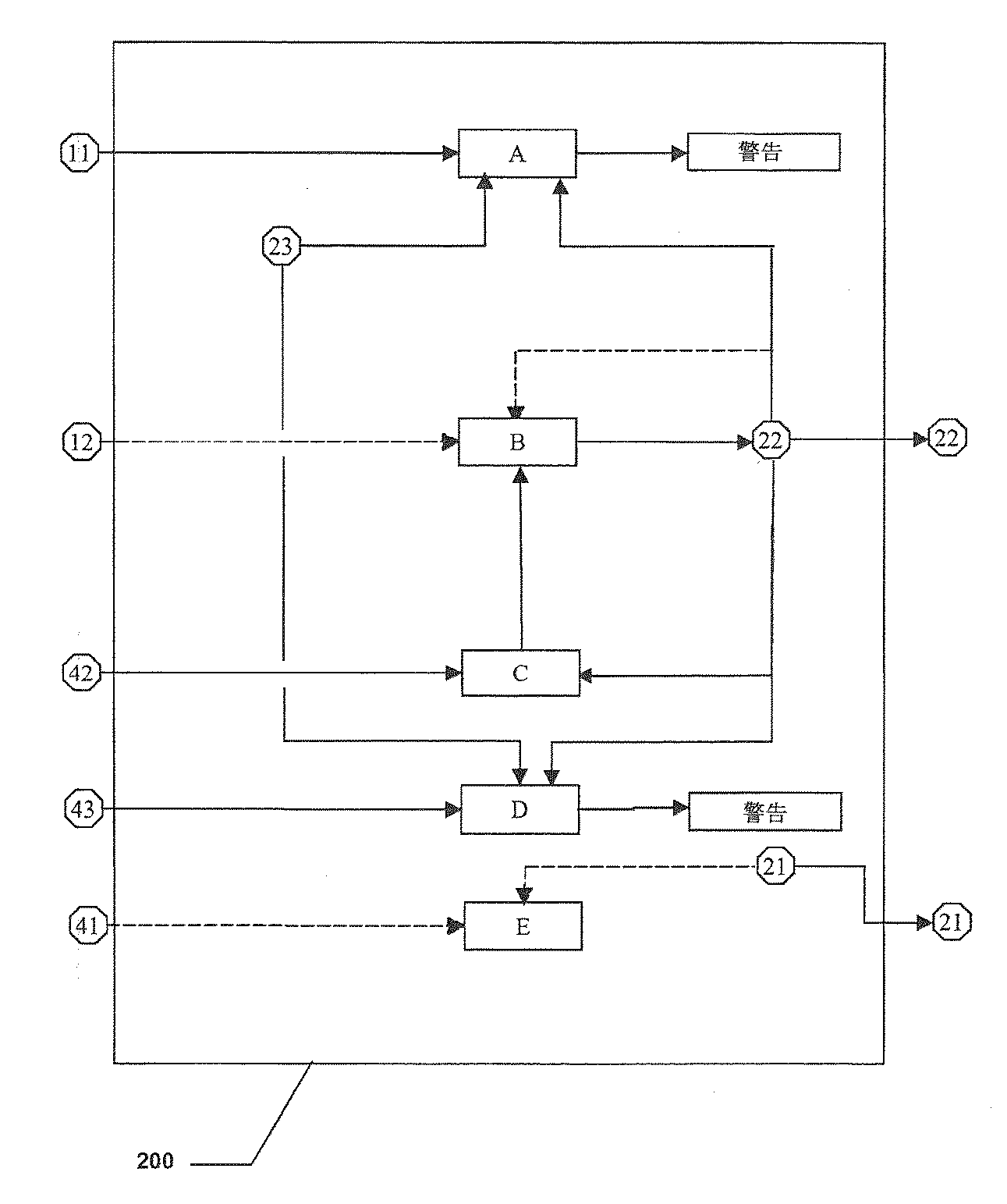
図2〜図4はそれぞれ、双眼視装置2を最適化するソフトウェア200のフローチャートの例、情報コンテンツ3を最適化するソフトウェア300のフローチャートの例、及び表示ソース4を最適化するソフトウェア400のフローチャートの例を示している。
2 to 4 respectively show an example of a flowchart of the
前記ソフトウェア200、300、及び400は一緒になって、本発明により立体視システム内で実行されるパラメータ管理ループを形成する。
The
これらは、着用者の右眼及び左眼によってそれぞれ見られる右画像及び左画像を作り出すように協働する。 These cooperate to produce a right image and a left image seen by the wearer's right eye and left eye, respectively.
図2〜図4の参照記号「A」〜「M」は、本発明による表示システムの1つ又は複数のパラメータのコンピュータ処理における1つ又は複数のステップを示している。
The reference symbols “A” to “M” in FIGS. 2 to 4 indicate one or more steps in the computer processing of one or more parameters of the display system according to the present invention.
図2において、双眼視装置2を最適化するソフトウェア200は、前記双眼視装置に特有のパラメータ、即ち、画像表示距離22及び双眼視装置2の瞳孔間距離23を扱い、前記双眼視装置2の垂直視差は20’未満である。
In FIG. 2,
画像表示距離22は、双眼視装置により焦点を絞った後に得られる画像の見かけの(apparent)距離に対応し、従って、視差に由来するものではない。
The
着用者の瞳孔間距離11は、双眼視装置2の瞳孔間距離23の手動又は自動調節によって、双眼視装置2内に組み込まれる。
The
特に、着用者の瞳孔間距離11を作り出す左右の半分の距離は、双眼視装置2の瞳孔間距離23の左右の半分の距離の手動又は自動調節によって双眼視装置2に組み込まれる。
In particular, the left and right half distances that create the wearer's
双眼視装置2を最適化するソフトウェア200はまた、着用者から来る、及び表示ソース4を最適化するソフトウェア400から来る様々な入力パラメータ、即ち着用者の瞳孔間距離11、中間レンダリング平面の距離42、及びカメラ間距離43、を処理するように働く。
The
双眼視装置2の着用者は、正視着用者、あるいは、補正眼鏡、コンタクトレンズ、及び前記双眼視装置2上に位置決めされた補正レンズのいずれか、を含むタイプの視力矯正を行なった屈折異常着用者であると考えられる。
The wearer of the
着用者の瞳孔間距離11及び双眼視装置の瞳孔間距離23、それに加えて画像の表示距離22は、図2のブロックAで処理されて、水平視差Ph1が絶対値で常に1.5°未満であることが保証される。
The wearer's
視差に関する追加の情報は、非特許文献1に与えられている。 Additional information on parallax is given in Non-Patent Document 1.
双眼視装置2の水平視差Ph1は、以下の式を使用して算出される。
式中、「IPDdevice23Left」は、双眼視装置の左半分の瞳孔間距離を示し、「IPDdevice23Right」は双眼視装置の右半分の瞳孔間距離を示し、「IPDwearer11Left」は着用者の左半分の瞳孔間距離を示し、「IPDwearer11Right」は着用者の右半分の瞳孔間距離を示し、「Image display distance 22」は画像表示距離22を示す。
In the formula, “IPDdevice23Left” indicates the interpupillary distance of the left half of the binocular vision device, “IPDdevice23Right” indicates the interpupillary distance of the right half of the binocular vision device, and “IPDwearer11Left” indicates the distance between the pupils of the left half of the wearer. “IPDwearer11Right” indicates the interpupillary distance of the wearer's right half, and “
最良の環境において、双眼視装置の瞳孔間距離23の調節が十分正確である場合、着用者が正視であるか、又は着用者が双眼視装置2だけでなく、1対の補正眼鏡、コンタクトレンズ、及び前記双眼視装置上に配置された1対の補正レンズのいずれかなどの補正システムを着用していると仮定すると、Ph1はほぼゼロに近い。
In the best environment, if the adjustment of the
水平視差Ph1が絶対値で1.5°より大きい場合、双眼視装置の瞳孔間距離23は、絶対値で1.5°未満であるPh1を得るように変更する必要がある。
When the horizontal parallax Ph1 is greater than 1.5 ° in absolute value, the
これは例えば、着用者の瞳孔間距離11に対する調節が双眼視装置2上で適切に設定されなかった場合に起こる可能性がある。
This may occur, for example, when adjustments to the wearer's
その場合、着用者には、眼精疲労及び不快感を抑制する最適立体視用の条件が満たされていない旨の警告が出される。 In that case, the wearer is warned that the conditions for optimal stereoscopic vision that suppresses eye strain and discomfort are not satisfied.
双眼視装置2が瞳孔間距離23の自動調節を行う場合、前記双眼視装置2内に記憶された瞳孔間距離23の値を着用者の瞳孔間距離11の値に等しくするように、その調節が開始される。
When the
これらの2つの値が等しい場合、双眼鏡装置は調節済みと考えられる。 If these two values are equal, the binocular device is considered adjusted.
さらに、特定のタイプの着用者では、水平視差Ph1を1.2°未満にすることが好ましい。 Further, for a specific type of wearer, it is preferable that the horizontal parallax Ph1 is less than 1.2 °.
このようにして変更された表示距離22は、図2のブロックBで処理され、ソフトウェア200によって様々なパラメータを最適化する際に考慮される。
The
表示ソースの中間レンダリング平面の距離42及び画像表示距離22が、図2のブロックCで処理される。
The intermediate
この処理の目的は、中間レンダリング平面の距離42と等しい表示距離22を得ることである。
The purpose of this process is to obtain a
表示距離22が中間レンダリング平面の距離42と異なる場合、その値は中間レンダリング平面の距離42の値に変えられる。
If the
場合によっては、図2に破線矢印で示すように、着用者の視力矯正12及び画像表示距離22を図2のブロックBで処理することができる。
In some cases, the wearer's
双眼視装置2の着用者の視力矯正12が誤っている場合、その視力矯正12は、画像の表示距離22に作用することによって間接的に修正することができる。
If the
従って、表示距離22が着用者の視力矯正12では見えない距離である場合、表示距離22は変更される。
Therefore, when the
このようにして変更された表示距離22は、図2のブロックBで処理され、様々なパラメータを最適化する際にソフトウェア200によって考慮される。
The
別の方法では、着用者が焦点の合った状態で観賞できるように、表示距離22を変えることなく補正レンズ51a、51bを使用することが可能である。
In another method, it is possible to use the
警告メッセージ、例えば音声メッセージにより、使用者に補正レンズ51a、51bを適切な位置に置くように想起させることができる。
A warning message, for example a voice message, can remind the user to place the
着用者の瞳孔間距離11は、双眼視装置2の瞳孔間距離23の手動、又は自動調節によって、双眼視装置2内に組み込まれる。
The
表示ソースのカメラ間距離43、双眼視装置の瞳孔間距離23、及び画像の表示距離22は、以下の式を用いて計算して水平視差Ph2の値をチェックするために、図2のブロックDで処理される。
式中、「IPDdevice23Left」は双眼視装置の左半分の瞳孔間距離を示し、「IPDdevice23Right」は双眼視装置の右半分の瞳孔間距離を示し、「Inter−camera distance 43Left」は表示ソースの左半分のカメラ間距離を示し、「Inter−camera distance 43Right」は表示ソースの右半分のカメラ間距離を示す。 In the formula, “IPDdevice23Left” indicates the interpupillary distance of the left half of the binocular vision device, “IPDdevice23Right” indicates the interpupillary distance of the right half of the binocular vision device, and “Inter-camera distance 43Left” indicates the left half of the display source. "Inter-camera distance 43Right" indicates the inter-camera distance of the right half of the display source.
水平視差Ph2が絶対値で1.5°より大きい場合、着用者は、眼精疲労及び不快感を抑制する最適立体視用の条件が満たされないという警告を受ける。 When the horizontal parallax Ph2 is larger than 1.5 ° in absolute value, the wearer receives a warning that the conditions for optimal stereoscopic vision that suppresses eye strain and discomfort are not satisfied.
さらに、左右スクリーン解像度21は、双眼視装置2に特有であり、パラメータ管理ループで考慮することができる追加のパラメータである。
Furthermore, the left and
表示ソースの表示解像度41及びスクリーン解像度21は、図2のブロックEで処理される。
表示解像度41がスクリーン解像度21より大きい場合、表示解像度41はスクリーン解像度21と同じ値を得るように小さくされる。
When the
表示解像度41がスクリーン解像度21より小さい場合、観賞システムは、画像を表示する前に内挿フィルタを用いて画像データを内挿し、それによって表示解像度41をスクリーン解像度21に揃える。
When the
従って、入力パラメータ11、12、41、42、及び43は、双眼視装置2の最適化ソフトウェア200によって処理されて、前記ソフトウェア200からの出力としてパラメータ21、22を得る。
Accordingly, the
管理ループは、前記出力パラメータ21及び/又は22を得て、情報コンテンツ3を最適化するソフトウェア300に運び、ここで前記ソフトウェア300用の入力パラメータを構成する。
The management loop obtains the
図3において、情報コンテンツ3を最適化するソフトウェア300は、前記情報コンテンツ3に特有のパラメータ、即ち、3種類のコンテンツタイプ31a〜31c、画像歪覚のマップ32、及び画像の空間周波数コンテンツ35を処理する。
ここで、3種類のコンテンツタイプとは、バーチャルコンテンツタイプ31aであるか、立体的に撮影又は取得されたリアルコンテンツタイプ32bであるか、あるいは、リアルであるが立体的ではないコンテンツタイプ31c、のいずれかである。
また、画像歪覚マップ32とは、画像間の歪覚の分布である。
In FIG. 3, the
Here, the three types of content are the
Further, the
情報コンテンツ3を最適化するソフトウェア300はまた、着用者、及び双眼視装置2を最適化するソフトウェア200から来る様々な入力パラメータ、即ち着用者の瞳孔間距離11及び画像表示距離22を処理できる。
The
情報コンテンツ3のコンテンツタイプが立体的に取得又は撮影されたリアルコンテンツタイプ31bである場合、前記コンテンツ3、着用者の瞳孔間距離11、及び画像表示距離22は、図3のブロックFで処理されて、以下の式を使用して、コンテンツタイプ31bの情報コンテンツ3に特有である「2つのカメラ間の角度33」を決定する。
When the content type of the
[数3]
「2つのカメラ間の角度33」= 「Angle 33Left」 + 「Angle 33Right」
ここで、
“
here,
式中、「IPDwearer 11Right」は着用者の右半分の瞳孔間距離を示し、「IPDwearer 11Left」は着用者の左半分の瞳孔間距離を示し、「Angle 33Left」は中間照準軸、即ち2つのカメラを結ぶ軸と垂直な軸に対する左半分の照準角を示し、「Angle 33Right」は中間照準軸、即ち2つのカメラを結ぶ軸と垂直な軸に対する左半分の照準角を示す。 Where “IPDwearer 11Right” indicates the interpupillary distance of the wearer's right half, “IPDwearer 11Left” indicates the interpupillary distance of the wearer's left half, and “Angle 33Left” is the intermediate aim axis, ie two cameras “Angle 33Right” indicates the aiming angle of the left half with respect to the intermediate aiming axis, that is, the axis perpendicular to the axis connecting the two cameras.
選択的には、図3に破線矢印で示すように、情報コンテンツが、立体的に取得又は撮影されたリアルタイプ(31b)か、非立体的リアルタイプ(31c)かに関わらず、リアルタイプである場合、前記コンテンツ及びスクリーン解像度21のが図3のブロックGで処理されて、スクリーン21の解像度と等しい、情報コンテンツタイプ31b又は31cに特有の画像解像度34が得られる。
Optionally, as indicated by the dashed arrows in FIG. 3, the information content is real type regardless of whether it is a real type (31b) acquired or photographed in three dimensions or a non-stereo real type (31c). In some cases, the content and
その結果、情報コンテンツ画像のサイズが最適化され、画像を立体視システムでより速く処理することができる。 As a result, the size of the information content image is optimized and the image can be processed more quickly by the stereoscopic system.
従って、入力パラメータ11、21、及び22は、情報コンテンツ3を最適化するソフトウェア300によって処理されて、前記ソフトウェアからの出力としてパラメータ32、33、35、及び、3種類のコンテンツタイプ31a、31b、又は31cのいずれかが得られる。
Accordingly, the
管理ループは、前記出力パラメータ31a、31b、31c、32、33、及び/又は35を得て、これらを前記ソフトウェア400への入力パラメータとして、表示ソース4を最適化するソフトウェア400に運ぶ。
The management loop obtains the
図4において、表示ソース4を最適化するソフトウェア400は、着用者1、双眼視装置2を最適化するソフトウェア200、及び情報コンテンツ3を最適化するソフトウェア300から来る様々な入力パラメータ、即ちバーチャルタイプ31a、立体的リアルタイプ31b、又は非立体的リアルタイプ31c、のいずれかである情報コンテンツタイプ、画像歪覚マップ32、及び画像の空間周波数コンテンツ35、及び情報コンテンツのタイプによっては、着用者の瞳孔間距離11、画像表示距離22、及び2つのカメラ間の角度33を処理する。
In FIG. 4, the
情報コンテンツがバーチャルタイプ31aのものである場合、前記バーチャルタイプ31aの情報コンテンツ及び画像表示距離22は図4のブロックIaで処理されて、表示ソース4に特有の、中間レンダリング平面の距離42aを得る。
If the information content is of the
従って、バーチャルタイプ31aのコンテンツによる画像を表示するのに使用されるバーチャルカメラのパラメータを設定するために、中間レンダリング平面の距離42aは表示距離22と等しい。
Therefore, the intermediate rendering plane distance 42a is equal to the
情報コンテンツが立体的に取得、又は撮影されたリアルコンテンツタイプ31bのものである場合、前記コンテンツタイプ31bの情報コンテンツ、2つのカメラ間の角度33、及び画像表示距離22は図4のブロックIJbで処理されて、中間レンダリング平面の距離42b及び表示ソース4に特有のカメラ間距離43bを得る。
When the information content is of the
従って、左右の画像を生成するためには、中間レンダリング平面の距離42bは表示距離22と等しい。
Therefore, in order to generate left and right images, the
2つのカメラ間の角度33により、以下の式を使用して、カメラ間距離43bを導出するのに中間レンダリング平面の距離42bを使用することが可能になる。
[数5]
「カメラ間距離43b」= tan(「2つのカメラ間の角度33」) * 「中間レンダリング平面の距離42b」
The
[Equation 5]
“
より詳細には、着用者の瞳孔間距離11が非対称である場合、2つのカメラ間の角度33は2つの半分の角度、「角度33Left」と「角度33Right」に分解され、一方が左側に、一方が右側にあり、カメラ間距離43bは2つのカメラ間距離に分解され、一方が左側に、一方が右側にある。
More specifically, if the wearer's
従って、カメラ間距離43bを得る式は以下の通りである。
[数6]
「カメラ間距離43b」= 「カメラ間距離43bLeft」 + 「カメラ間距離43bRight」
Therefore, the equation for obtaining the
[Equation 6]
“
ここで、
[数7]
「カメラ間距離43bLeft」= tan(「角度33Left」) * 「中間レンダリング平面の距離42b」
[数8]
「カメラ間距離43bRight」= tan(「角度33Right」) * 「中間レンダリング平面の距離42b」
here,
[Equation 7]
“
[Equation 8]
“Inter-camera distance 43bRight” = tan (“angle 33Right”) * “intermediate
従って、着用者の瞳孔間距離におけるあらゆる非対称性の関数として、中間レンダリング平面の距離42bとカメラ間距離43bの間の値をとるように重み付けられた、全体的比例定数に従う必要がある。
It is therefore necessary to follow an overall proportionality constant that is weighted to take a value between the intermediate
これは、パラメータ42b、43bを両方とも同時に、且つ系統的に調節することを暗示している。例として、この調節は、中間レンダリング平面42bの距離に対して2つのカメラそれぞれのレンズで行なわれる。
This implies that both
情報コンテンツが非立体的リアルタイプ31cのものである場合、前記コンテンツタイプ31cのコンテンツ及び画像表示距離22はIcで処理されて、前記コンテンツタイプ31cのコンテンツに特有の中間レンダリング平面の距離42cを得る。
If the information content is of the non-stereoscopic
従って、左右の画像を生成するために、中間レンダリング平面の距離42cは表示距離22と等しい。
Therefore, the
バーチャルタイプ31aのコンテンツは、着用者の瞳孔間距離11、及び中間レンダリング平面の距離42aと共に、Jaで処理されて、表示ソース4に特有のカメラ間距離43aを得る。
The content of the
従って、中間レンダリング平面の距離42aに従って、水平視差が絶対値で1.5°未満であるという条件を満たすために、表示ソースの左右のカメラ間距離43aは以下の許容範囲で着用者の瞳孔間距離11と等しい。
非立体的リアルタイプ31cのコンテンツは、着用者の瞳孔間距離11及び中間レンダリング平面42cの距離と共に、Jcで処理されて、前記コンテンツタイプ31cに特有の表示ソースのカメラ間距離43cを得る。
The content of the non-stereoscopic
従って、中間レンダリング平面の距離42cに従って、水平視差が絶対値で1.5°未満であるという条件を満たすために、表示ソースの左右のカメラ間距離43cは、以下の許容範囲で、着用者の瞳孔間距離11と等しい。
画像歪覚マップ32は、画像の空間周波数コンテンツ35のパラメータと共に、Kで処理されて、表示ソース4に特有のフィルタリングされた空間周波数コンテンツ44を得る。
The
フィルタリングアルゴリズムは、周波数コンテンツ35よりも眼を疲れさせない周波数コンテンツ44を得るために、空間周波数をフィルタリングするように働き、このタイプのフィルタリングは立体表示システムの複数の焦点面がないことによる影響を小さくするように働く。これにより、瞳孔近見衝突(accommodation−convergence conflicts)による疲労が小さくなる。
The filtering algorithm works to filter the spatial frequency in order to obtain
このタイプのアルゴリズムは、当業者によく知られており、眼精疲労を抑制するために、空間周波数と歪覚が両立しない点をマスキングするか、又は画像の融合を容易にするために空間周波数コンテンツの高周波部分をカットする。 This type of algorithm is well known to those skilled in the art and masks the point where spatial frequency and distortion are incompatible to suppress eye strain or spatial frequency to facilitate image fusion. Cut the high frequency part of the content.
周波数フィルタ方法の例は、非特許文献2に記載されている。
An example of the frequency filter method is described in
バーチャルタイプ31aのコンテンツは、中間レンダリング平面の距離42aと共に、Lで処理されて、表示ソース4に特有の表示距離45を得る。
The content of the
前記表示距離45は、最小表示距離と最大表示距離の間にある。
The
これらの最小、最大距離は、「パーヌム野」(Panum’s area)の表示条件に従う必要がある。 These minimum and maximum distances need to follow the display conditions of “Panum's area”.
非特許文献3に記載されている「パーヌム野」は、左右の画像を融合して視野の立体化を可能にする空間領域に対応する。
The “Pernum field” described in
図4のブロックLでの処理は、与えられた表示コンテンツに対してパーヌム野の条件に従って、上記ブロック処理Iaの処理によって得られた中間レンダリング平面の距離42aにある平面を中間平面として使用して、前記平面の前、後での表示緯度を決定する。 The process in the block L in FIG. 4 uses the plane at the distance 42a of the intermediate rendering plane obtained by the process of the block process Ia as the intermediate plane according to the condition of the pernum field for the given display content. The display latitude before and after the plane is determined.
従って、最小距離より小さい距離に対しては、装置はあらゆるバーチャルタイプ31aのコンテンツを表示せず、これは最大距離より大きい距離に対しても当てはまる。
Thus, for distances less than the minimum distance, the device does not display any
この処理はまた、バーチャルタイプ31aのコンテンツの表示スケールの変更の可能性を暗示し、それによって表示されるシーンは最小、最大表示距離に従う。これは、バーチャルタイプ31aのコンテンツの表示に使用されるバーチャルカメラのパラメータを設定する(その焦点距離を変更する)ことになる。
This process also implies the possibility of changing the display scale of the content of the
選択的には、図4に破線矢印で示すように、双眼視装置2に特有のスクリーン解像度21は、図4のブロックHで処理して、表示ソース4の表示解像度41がスクリーン解像度21と等しくなるように、双眼視装置に適合された表示ソースを得ることができる。
Optionally, as indicated by the dashed arrows in FIG. 4, the
さらに、情報コンテンツがバーチャルタイプ31aのコンテンツである場合、前記バーチャルタイプ31aのコンテンツ、着用者の頭部の位置と方向13を図4のブロックMで処理して、カメラ間の中間点の位置、及び2つのバーチャルカメラの照準軸の照準方向を得ることができる。
Further, when the information content is a
図4のブロックMでの処理はリアルタイムで動作し、着用者がバーチャルタイプ31aのコンテンツで規定された基準フレーム内を移動している間、カメラの位置とその中間照準角を、着用者の頭部の位置と方向13に関するデータに対応させる。
The processing in block M of FIG. 4 operates in real time, and while the wearer is moving within the reference frame defined by the content of the
従って、コンテンツタイプに係る入力パラメータ31a、31b、又は31c、並びに入力パラメータ11、13、21、22、32、33、及び35は、表示ソース4を最適化するソフトウェア400によって処理されて、前記ソフトウェア400からの出力としてパラメータ41、42、及び/又は43が得られる。
Accordingly, the
管理ループは、前記出力パラメータ41、42、及び/又は43をとり、前記ソフトウェア200用の入力パラメータとして双眼視装置2を最適化するソフトウェア200にこれらを運ぶ。
The management loop takes the
図5は、図2〜図4によって示されるような、本発明による複数の最適化ソフトウェアで作られた例示的なパラメータ管理ループを示している。 FIG. 5 illustrates an exemplary parameter management loop made with multiple optimization software according to the present invention, as illustrated by FIGS.
着用者に特有であり、パラメータ管理ループに必要な少なくとも1つのパラメータが、例えば、双眼視装置を最適化するソフトウェア200内に記憶され、入力パラメータとして、情報コンテンツタイプにもよるが、ソフトウェア300、及び/又はソフトウェア400に伝達される。
At least one parameter specific to the wearer and required for the parameter management loop is stored, for example, in the
ソフトウェア200からの出力パラメータは、入力パラメータとしてソフトウェア300に伝達され、ここで前記ソフトウェア300によって処理される。
Output parameters from the
ソフトウェア300からの出力パラメータは、入力パラメータとしてソフトウェア400に伝達され、前記ソフトウェア400によって処理される。
Output parameters from the
ソフトウェア400からの出力パラメータは、入力パラメータとしてソフトウェア200に伝達され、前記ソフトウェア200によって処理される。
Output parameters from the
別の変更形態では、着用者に特有でありパラメータ管理ループ内で必要な(1つ、又は複数の)パラメータは、例えば情報コンテンツを最適化するソフトウェア300内に記憶することができ、情報コンテンツタイプによっては選択的に、入力パラメータとしてソフトウェア200、及び/又はソフトウェア400に伝達できる。
In another variation, the parameter (s) specific to the wearer and required in the parameter management loop can be stored, for example, in the
又は実際、使用者に特有でありパラメータ管理ループが必要とする(1つ、又は複数の)パラメータは例えば、表示ソースを最適化するソフトウェア400内に記憶することができ、情報コンテンツタイプによっては選択的に、入力パラメータとしてソフトウェア200、及び/又はソフトウェア300に伝達できる。
Or, in fact, the parameter (s) that are specific to the user and required by the parameter management loop can be stored, for example, in
本発明は、上に記載した例示的な実施に限らず、より一般的には、本発明の明細書で与えられた一般的な指示に基づいて想定することができるあらゆる立体視システムに関連する。 The invention is not limited to the exemplary implementations described above, but more generally relates to any stereoscopic system that can be envisaged based on the general instructions given in the specification of the invention. .
特に、それぞれ双眼視装置2、情報コンテンツ3、及び表示ソース4を最適化する複数のソフトウェア200、300、及び400は、コンピュータタイプの表示ソース4内に一括して組み込むことができる。
In particular, a plurality of
1 表示システム
2 双眼視装置
3 (情報)コンテンツ
4 表示ソース
11 (着用者の)瞳孔間距離
12 視力矯正
13 頭部の位置と方向
21 スクリーン解像度
22 (画像)表示距離
23 (双眼視装置)の瞳孔間距離
31a バーチャルコンテンツタイプ、バーチャルタイプ
31b 立体的に撮影又は取得されたリアルコンテンツタイプ、立体的リアルタイプ
31c リアルであるが立体的ではないコンテンツタイプ、非立体的リアルタイプ
32 画像歪覚マップ
33 2つのカメラ間の角度
34 画像解像度
35 (画像の空間)周波数コンテンツ
41 (表示ソースの)表示解像度
42、42a、42b、42c 中間レンダリング平面の距離
43、43b カメラ間距離
44 (フィルタリングされた空間)周波数コンテンツ
45 表示距離
50a、50b 画像入力
51a、51b 視力矯正レンズ
52a、52b U字形レール
200 (双眼視装置を最適化する)ソフトウェア
300 (情報コンテンツを最適化する)ソフトウェア
400 (表示ソースを最適化する)ソフトウェア
DESCRIPTION OF SYMBOLS 1
Claims (23)
さらに、前記双眼視装置(2)、前記情報コンテンツ(3)、及び前記表示ソース(4)を最適化するソフトウェア(200、300、400)を実行する電子コンポーネントを備えており、
前記最適化ソフトウェアは一緒になって、
a)前記双眼視装置(2)及び前記情報コンテンツ(3)を最適化する前記ソフトウェア(200、300)への入力パラメータを構成する、着用者の瞳孔間の距離(11)、b)前記情報コンテンツ(3)を最適化する前記ソフトウェア(300)への入力パラメータである、前記双眼視装置(2)を最適化する前記ソフトウェア(200)からの少なくとも1つの出力パラメータ、c)前記表示ソース(4)を最適化する前記ソフトウェア(400)への入力パラメータである、前記情報コンテンツ(3)を最適化する前記ソフトウェア(300)からの出力パラメータ、及びd)前記双眼視装置(2)を最適化する前記ソフトウェア(200)への入力パラメータである、前記表示ソース(4)を最適化する前記ソフトウェア(400)からの出力パラメータ、
を管理するループを形成し、
複数の前記最適化ソフトウェア(200、300、400)からの前記出力パラメータは、前記着用者の生理機能に最もよく適合する条件下で前記双眼視装置(2)により、前記情報コンテンツ(3)を観賞できるように、前記着用者の瞳孔間の距離に適合されていることを特徴とする立体視用表示システム。 A stereoscopic display system comprising a binocular vision device (2), an information content (3), and a display source (4),
And an electronic component for executing software (200, 300, 400) for optimizing the binocular vision device (2), the information content (3), and the display source (4),
Together, the optimization software
a) Distance between wearer's pupils (11), b) said information comprising input parameters to said binocular vision device (2) and said software (200, 300) for optimizing said information content (3) At least one output parameter from the software (200) for optimizing the binocular vision device (2), which is an input parameter to the software (300) for optimizing the content (3), c) the display source ( 4) is an input parameter to the software (400) that optimizes, the output parameter from the software (300) that optimizes the information content (3), and d) the binocular vision device (2) is optimized The software (400) that optimizes the display source (4), which is an input parameter to the software (200) to be converted Output parameters from,
Form a loop to manage
The output parameters from a plurality of the optimization software (200, 300, 400) are used to convert the information content (3) by the binocular vision device (2) under conditions that best suit the wearer's physiology. A stereoscopic display system characterized in that it is adapted to the distance between the wearer's pupils so that it can be viewed.
The display source (4) is selected from a computer, a game console, or a portable video player, and is a device having both or one function of video reading and display. The display system for stereoscopic vision as described in any one of 21.
Applications Claiming Priority (3)
| Application Number | Priority Date | Filing Date | Title |
|---|---|---|---|
| FR0654111A FR2906899B1 (en) | 2006-10-05 | 2006-10-05 | DISPLAY DEVICE FOR STEREOSCOPIC VISUALIZATION. |
| FR0654111 | 2006-10-05 | ||
| PCT/FR2007/052077 WO2008040918A2 (en) | 2006-10-05 | 2007-10-04 | Display device for stereoscopic display |
Publications (2)
| Publication Number | Publication Date |
|---|---|
| JP2010506476A true JP2010506476A (en) | 2010-02-25 |
| JP5419011B2 JP5419011B2 (en) | 2014-02-19 |
Family
ID=37963814
Family Applications (1)
| Application Number | Title | Priority Date | Filing Date |
|---|---|---|---|
| JP2009530921A Active JP5419011B2 (en) | 2006-10-05 | 2007-10-04 | Stereoscopic display system |
Country Status (6)
| Country | Link |
|---|---|
| US (1) | US8896675B2 (en) |
| EP (1) | EP2070338B1 (en) |
| JP (1) | JP5419011B2 (en) |
| ES (1) | ES2395147T3 (en) |
| FR (1) | FR2906899B1 (en) |
| WO (1) | WO2008040918A2 (en) |
Cited By (2)
| Publication number | Priority date | Publication date | Assignee | Title |
|---|---|---|---|---|
| JP2016528761A (en) * | 2013-06-08 | 2016-09-15 | 株式会社ソニー・インタラクティブエンタテインメント | System and method for customizing the optical representation of a display provided by a head mounted display based on the user's optical prescription |
| JP2021532681A (en) * | 2018-07-30 | 2021-11-25 | アップル インコーポレイテッドApple Inc. | Electronic device system with auxiliary lens |
Families Citing this family (34)
| Publication number | Priority date | Publication date | Assignee | Title |
|---|---|---|---|---|
| DE102007033239A1 (en) * | 2007-07-13 | 2009-01-15 | Visumotion Gmbh | Method for processing a spatial image |
| US8786675B2 (en) * | 2008-01-23 | 2014-07-22 | Michael F. Deering | Systems using eye mounted displays |
| WO2009094587A1 (en) * | 2008-01-23 | 2009-07-30 | Deering Michael F | Eye mounted displays |
| US9812096B2 (en) | 2008-01-23 | 2017-11-07 | Spy Eye, Llc | Eye mounted displays and systems using eye mounted displays |
| US9325972B2 (en) * | 2008-09-29 | 2016-04-26 | Two Pic Mc Llc | Actor-mounted motion capture camera |
| US9106925B2 (en) * | 2010-01-11 | 2015-08-11 | Ubiquity Holdings, Inc. | WEAV video compression system |
| EP2627092B1 (en) * | 2010-10-08 | 2018-02-28 | LG Electronics Inc. | Three-dimensional glasses, three-dimensional image display apparatus, and method for driving the three-dimensional glasses and the three-dimensional image display apparatus |
| US20120098971A1 (en) * | 2010-10-22 | 2012-04-26 | Flir Systems, Inc. | Infrared binocular system with dual diopter adjustment |
| US8773515B2 (en) * | 2011-07-08 | 2014-07-08 | Seung-Min Park | Control method and apparatus for displaying moving pictures |
| US9414049B2 (en) * | 2011-09-19 | 2016-08-09 | Écrans Polaires Inc./Polar Screens Inc. | Method and display for showing a stereoscopic image |
| KR101926577B1 (en) * | 2012-02-23 | 2018-12-11 | 한국전자통신연구원 | Expanded 3D stereoscopic display system |
| JP5919899B2 (en) * | 2012-03-08 | 2016-05-18 | セイコーエプソン株式会社 | Virtual image display device and method for adjusting position of virtual image display device |
| EP2680593A1 (en) * | 2012-06-26 | 2014-01-01 | Thomson Licensing | Method of adapting 3D content to an observer wearing prescription glasses |
| EP2699006A1 (en) * | 2012-08-16 | 2014-02-19 | ESSILOR INTERNATIONAL (Compagnie Générale d'Optique) | Pictures positioning on display elements |
| FR3005194B1 (en) * | 2013-04-25 | 2016-09-23 | Essilor Int | METHOD FOR CUSTOMIZING AN IMAGE DISPLAY ELECTRONIC DEVICE |
| GB201310360D0 (en) * | 2013-06-11 | 2013-07-24 | Sony Comp Entertainment Europe | Head-Mountable apparatus and systems |
| US9993335B2 (en) | 2014-01-08 | 2018-06-12 | Spy Eye, Llc | Variable resolution eye mounted displays |
| JPWO2015107817A1 (en) * | 2014-01-20 | 2017-03-23 | ソニー株式会社 | Image display device, image display method, image output device, image output method, and image display system |
| CN103955060A (en) * | 2014-05-10 | 2014-07-30 | 莫永平 | Head-worn wireless video glasses |
| US10268041B2 (en) | 2014-05-24 | 2019-04-23 | Amalgamated Vision Llc | Wearable display for stereoscopic viewing |
| US9877016B2 (en) | 2015-05-27 | 2018-01-23 | Google Llc | Omnistereo capture and render of panoramic virtual reality content |
| EP3304195A1 (en) | 2015-05-27 | 2018-04-11 | Google LLC | Camera rig and stereoscopic image capture |
| US10038887B2 (en) | 2015-05-27 | 2018-07-31 | Google Llc | Capture and render of panoramic virtual reality content |
| CN105182535B (en) * | 2015-09-28 | 2018-04-20 | 大连楼兰科技股份有限公司 | How to Use Smart Glasses for Car Maintenance |
| CA3022880A1 (en) * | 2016-05-05 | 2017-11-09 | Robert D. Watson | Surgical stereoscopic visualization system with movable head mounted display |
| WO2017217115A1 (en) * | 2016-06-17 | 2017-12-21 | ソニー株式会社 | Image processing device, image processing method, program, and image processing system |
| US10812693B2 (en) | 2017-10-20 | 2020-10-20 | Lucasfilm Entertainment Company Ltd. | Systems and methods for motion capture |
| CN108761801B (en) * | 2018-08-17 | 2020-10-02 | 杨建明 | Simple and practical augmented reality glasses |
| US10823970B2 (en) | 2018-08-23 | 2020-11-03 | Apple Inc. | Head-mounted electronic display device with lens position sensing |
| CN209690628U (en) | 2018-08-23 | 2019-11-26 | 苹果公司 | System and headset equipment |
| CN113376833B (en) * | 2020-02-25 | 2025-01-14 | 东莞双营光电科技有限公司 | Image adjustment system and method corresponding to pupil distance of micro head mounted display |
| WO2021237065A1 (en) | 2020-05-21 | 2021-11-25 | Looking Glass Factory, Inc. | System and method for holographic image display |
| US11415935B2 (en) | 2020-06-23 | 2022-08-16 | Looking Glass Factory, Inc. | System and method for holographic communication |
| WO2022119940A1 (en) | 2020-12-01 | 2022-06-09 | Looking Glass Factory, Inc. | System and method for processing three dimensional images |
Citations (8)
| Publication number | Priority date | Publication date | Assignee | Title |
|---|---|---|---|---|
| JPH0795621A (en) * | 1993-09-21 | 1995-04-07 | Canon Inc | Image recording / reproducing device |
| JPH08194187A (en) * | 1995-01-18 | 1996-07-30 | Seiko Epson Corp | Head-mounted display device |
| JPH10164448A (en) * | 1996-12-02 | 1998-06-19 | Sanyo Electric Co Ltd | Method and device for reproducing image for television broadcasting system |
| JP2000115650A (en) * | 1998-10-09 | 2000-04-21 | Matsushita Electric Ind Co Ltd | Software update method for digital television receiver using recorded data |
| JP2002095018A (en) * | 2000-09-12 | 2002-03-29 | Canon Inc | Image display control device, image display system, and image data display method |
| JP2005073049A (en) * | 2003-08-26 | 2005-03-17 | Sharp Corp | 3D image reproduction apparatus and 3D image reproduction method |
| JP2006108868A (en) * | 2004-10-01 | 2006-04-20 | Canon Inc | Image display device and image display system |
| JP2006135884A (en) * | 2004-11-09 | 2006-05-25 | Konica Minolta Photo Imaging Inc | Video display device |
Family Cites Families (78)
| Publication number | Priority date | Publication date | Assignee | Title |
|---|---|---|---|---|
| US2715852A (en) * | 1950-07-12 | 1955-08-23 | American Optical Corp | Eye testing instruments |
| US4757378A (en) * | 1986-09-30 | 1988-07-12 | The Boeing Company | Monocular scene generator for biocular wide field of view display system |
| GB8715184D0 (en) * | 1987-06-29 | 1987-10-21 | Gec Avionics | Stereoscopic presentation of data |
| JP3129719B2 (en) * | 1989-04-21 | 2001-01-31 | 株式会社パルカ | Video display device |
| JP2985231B2 (en) * | 1990-05-17 | 1999-11-29 | ソニー株式会社 | Video display device |
| US5880773A (en) * | 1991-12-27 | 1999-03-09 | Sony Corporation | Head mounted display configured to a user's physical features |
| US5467104A (en) * | 1992-10-22 | 1995-11-14 | Board Of Regents Of The University Of Washington | Virtual retinal display |
| JP3309443B2 (en) * | 1992-10-28 | 2002-07-29 | ソニー株式会社 | Glasses-type viewer |
| US5539422A (en) * | 1993-04-12 | 1996-07-23 | Virtual Vision, Inc. | Head mounted display system |
| US5388990A (en) * | 1993-04-23 | 1995-02-14 | The United States Of America As Represented By The Administrator Of The National Aeronautics And Space Administration | Virtual reality flight control display with six-degree-of-freedom controller and spherical orientation overlay |
| JPH06331928A (en) * | 1993-05-24 | 1994-12-02 | Sony Corp | Eyeglass type display device |
| DE69417824D1 (en) * | 1993-08-26 | 1999-05-20 | Matsushita Electric Industrial Co Ltd | Stereoscopic scanner |
| US5543816A (en) * | 1993-10-07 | 1996-08-06 | Virtual Vision | Head mounted display system with aspheric optics |
| EP0724758A4 (en) * | 1993-10-07 | 1998-03-04 | Virtual Vision Inc | Binocular head mounted display system |
| US7310072B2 (en) * | 1993-10-22 | 2007-12-18 | Kopin Corporation | Portable communication display device |
| FR2715479B1 (en) * | 1994-01-25 | 1996-03-15 | Sextant Avionique | Control device for adjusting the position and orientation of a helmet relative to the head of a helmet wearer. |
| JPH0829725A (en) * | 1994-05-10 | 1996-02-02 | Canon Inc | Compound-eye image display device |
| WO1996000406A1 (en) * | 1994-06-23 | 1996-01-04 | Seiko Epson Corporation | Head-mounted display device |
| JP3433558B2 (en) * | 1995-02-28 | 2003-08-04 | ソニー株式会社 | Display device |
| US5583795A (en) * | 1995-03-17 | 1996-12-10 | The United States Of America As Represented By The Secretary Of The Army | Apparatus for measuring eye gaze and fixation duration, and method therefor |
| US5767820A (en) * | 1995-05-09 | 1998-06-16 | Virtual Research Systems | Head-mounted visual display apparatus |
| DE69706611T2 (en) * | 1996-06-27 | 2002-07-04 | Kabushiki Kaisha Toshiba, Kawasaki | Stereoscopic display system and method |
| JP3771973B2 (en) * | 1996-09-26 | 2006-05-10 | オリンパス株式会社 | 3D image display device |
| JP3787939B2 (en) * | 1997-02-27 | 2006-06-21 | コニカミノルタホールディングス株式会社 | 3D image display device |
| JP3801790B2 (en) * | 1998-09-28 | 2006-07-26 | Necディスプレイソリューションズ株式会社 | Image display device |
| US7346174B1 (en) * | 1998-10-05 | 2008-03-18 | Clive Smith | Medical device with communication, measurement and data functions |
| US6310982B1 (en) * | 1998-11-12 | 2001-10-30 | Oec Medical Systems, Inc. | Method and apparatus for reducing motion artifacts and noise in video image processing |
| US6480174B1 (en) * | 1999-10-09 | 2002-11-12 | Optimize Incorporated | Eyeglass-mount display having personalized fit module |
| US20020034004A1 (en) * | 2000-07-14 | 2002-03-21 | Stereovision Imaging, Inc. | Optically multiplexed hand-held digital binocular system |
| US20020057228A1 (en) * | 2000-11-14 | 2002-05-16 | Sina Fateh | Wearable display having ergonomically positioned microdisplay |
| JP4598966B2 (en) * | 2001-02-06 | 2010-12-15 | オリンパス株式会社 | Head-mounted video / audio playback system |
| KR100406945B1 (en) * | 2001-02-19 | 2003-11-28 | 삼성전자주식회사 | Wearable display apparatus |
| KR20020088226A (en) * | 2001-05-18 | 2002-11-27 | 삼성전자 주식회사 | Head mount display |
| US6963454B1 (en) * | 2002-03-01 | 2005-11-08 | Research Foundation Of The University Of Central Florida | Head-mounted display by integration of phase-conjugate material |
| JP2003018619A (en) * | 2001-07-03 | 2003-01-17 | Olympus Optical Co Ltd | Three-dimensional image evaluation apparatus and display using the same |
| WO2003034705A2 (en) * | 2001-10-19 | 2003-04-24 | University Of North Carolina At Chapel Hill | Methods and systems for dynamic virtual convergence and head mountable display |
| US7229174B2 (en) * | 2002-03-28 | 2007-06-12 | Nokia Corporation | Method to detect misalignment and distortion in near-eye displays |
| US7103212B2 (en) * | 2002-11-22 | 2006-09-05 | Strider Labs, Inc. | Acquisition of three-dimensional images by an active stereo technique using locally unique patterns |
| JP2004186863A (en) * | 2002-12-02 | 2004-07-02 | Amita Technology Kk | Stereophoscopic vision display unit and stereophoscopic vision signal processing circuit |
| US6879443B2 (en) | 2003-04-25 | 2005-04-12 | The Microoptical Corporation | Binocular viewing system |
| JP4364002B2 (en) * | 2004-02-06 | 2009-11-11 | オリンパス株式会社 | Head-mounted camera and photographing method using head-mounted camera |
| US7660472B2 (en) * | 2004-02-10 | 2010-02-09 | Headplay (Barbados) Inc. | System and method for managing stereoscopic viewing |
| JP3790764B2 (en) * | 2004-04-02 | 2006-06-28 | 一成 江良 | Projection display device and projection display system |
| WO2006058188A2 (en) * | 2004-11-24 | 2006-06-01 | Kopin Corporation | Binocular display system with two alignment fixtures |
| US20100232016A1 (en) * | 2005-09-28 | 2010-09-16 | Mirage Innovations Ltd. | Stereoscopic Binocular System, Device and Method |
| FR2891922B1 (en) * | 2005-10-06 | 2007-12-07 | Essilor Int | BINOCULAR INFORMATION DISPLAY DEVICE |
| WO2007070721A2 (en) * | 2005-12-15 | 2007-06-21 | Michael Mehrle | Stereoscopic imaging apparatus incorporating a parallax barrier |
| US7515344B2 (en) * | 2006-01-04 | 2009-04-07 | Vuzlx Corporation | Binocular display with improved contrast uniformity |
| US8668334B2 (en) * | 2006-02-27 | 2014-03-11 | Vital Art And Science Incorporated | Vision measurement and training system and method of operation thereof |
| JP4693900B2 (en) * | 2006-04-07 | 2011-06-01 | シャープ株式会社 | Image processing device |
| FR2900475B1 (en) * | 2006-04-26 | 2008-10-31 | Essilor Int | DISPLAY COMPRISING A PAIR OF BINOCULAR GLASSES AND WITH A DEVICE FOR ADJUSTING THE IMAGE |
| TWI308845B (en) * | 2006-06-07 | 2009-04-11 | Himax Display Inc | Head-mounted display and image adjusting method for the same |
| US8040600B2 (en) * | 2006-06-15 | 2011-10-18 | Kopin Corporation | Binocular display having an adjustment system |
| US7511684B2 (en) * | 2006-07-31 | 2009-03-31 | Motorola, Inc. | Image alignment method for binocular eyewear displays |
| US20100060723A1 (en) * | 2006-11-08 | 2010-03-11 | Nec Corporation | Display system |
| US9300949B2 (en) * | 2007-01-29 | 2016-03-29 | David J. Ahearn | Multi-view system |
| WO2009041055A1 (en) * | 2007-09-26 | 2009-04-02 | Panasonic Corporation | Beam scan type display device, its display method, program, and integrated circuit |
| US20090109513A1 (en) * | 2007-10-31 | 2009-04-30 | Motorola, Inc. | Head mounted display having electrowetting optical reflecting surface |
| US8269692B2 (en) * | 2007-11-20 | 2012-09-18 | Panasonic Corporation | Image display apparatus, display method thereof, program, integrated circuit, goggle-type head-mounted display, vehicle, binoculars, and desktop display |
| JP5347717B2 (en) * | 2008-08-06 | 2013-11-20 | ソニー株式会社 | Image processing apparatus, image processing method, and program |
| JP2010045584A (en) * | 2008-08-12 | 2010-02-25 | Sony Corp | Solid image correcting apparatus, solid image correcting method, solid image display, solid image reproducing apparatus, solid image presenting system, program, and recording medium |
| US20100110368A1 (en) * | 2008-11-02 | 2010-05-06 | David Chaum | System and apparatus for eyeglass appliance platform |
| US8259159B2 (en) * | 2009-01-12 | 2012-09-04 | Hu Chao | Integrative spectacle-shaped stereoscopic video multimedia device |
| US8320623B2 (en) * | 2009-06-17 | 2012-11-27 | Lc Technologies, Inc. | Systems and methods for 3-D target location |
| US8964013B2 (en) * | 2009-12-31 | 2015-02-24 | Broadcom Corporation | Display with elastic light manipulator |
| GB2478156A (en) * | 2010-02-26 | 2011-08-31 | Sony Corp | Method and apparatus for generating a disparity map for stereoscopic images |
| US20120249797A1 (en) * | 2010-02-28 | 2012-10-04 | Osterhout Group, Inc. | Head-worn adaptive display |
| US8467133B2 (en) * | 2010-02-28 | 2013-06-18 | Osterhout Group, Inc. | See-through display with an optical assembly including a wedge-shaped illumination system |
| US20120212499A1 (en) * | 2010-02-28 | 2012-08-23 | Osterhout Group, Inc. | System and method for display content control during glasses movement |
| JP5494153B2 (en) * | 2010-04-08 | 2014-05-14 | ソニー株式会社 | Image display method for head mounted display |
| US8564647B2 (en) * | 2010-04-21 | 2013-10-22 | Canon Kabushiki Kaisha | Color management of autostereoscopic 3D displays |
| DE102010024666A1 (en) * | 2010-06-18 | 2011-12-22 | Hella Kgaa Hueck & Co. | Method for optical self-diagnosis of a camera system and apparatus for carrying out such a method |
| JP5673032B2 (en) * | 2010-11-29 | 2015-02-18 | ソニー株式会社 | Image processing apparatus, display apparatus, image processing method, and program |
| US20120133747A1 (en) * | 2010-11-29 | 2012-05-31 | Sony Corporation | Image processing apparatus, display apparatus, image processing method and image processing program |
| US9690099B2 (en) * | 2010-12-17 | 2017-06-27 | Microsoft Technology Licensing, Llc | Optimized focal area for augmented reality displays |
| US9600923B2 (en) * | 2011-05-26 | 2017-03-21 | Thomson Licensing | Scale-independent maps |
| KR101926577B1 (en) * | 2012-02-23 | 2018-12-11 | 한국전자통신연구원 | Expanded 3D stereoscopic display system |
| US9031356B2 (en) * | 2012-03-20 | 2015-05-12 | Dolby Laboratories Licensing Corporation | Applying perceptually correct 3D film noise |
-
2006
- 2006-10-05 FR FR0654111A patent/FR2906899B1/en not_active Expired - Fee Related
-
2007
- 2007-04-10 US US12/311,435 patent/US8896675B2/en active Active
- 2007-10-04 EP EP07858508A patent/EP2070338B1/en active Active
- 2007-10-04 ES ES07858508T patent/ES2395147T3/en active Active
- 2007-10-04 WO PCT/FR2007/052077 patent/WO2008040918A2/en not_active Ceased
- 2007-10-04 JP JP2009530921A patent/JP5419011B2/en active Active
Patent Citations (8)
| Publication number | Priority date | Publication date | Assignee | Title |
|---|---|---|---|---|
| JPH0795621A (en) * | 1993-09-21 | 1995-04-07 | Canon Inc | Image recording / reproducing device |
| JPH08194187A (en) * | 1995-01-18 | 1996-07-30 | Seiko Epson Corp | Head-mounted display device |
| JPH10164448A (en) * | 1996-12-02 | 1998-06-19 | Sanyo Electric Co Ltd | Method and device for reproducing image for television broadcasting system |
| JP2000115650A (en) * | 1998-10-09 | 2000-04-21 | Matsushita Electric Ind Co Ltd | Software update method for digital television receiver using recorded data |
| JP2002095018A (en) * | 2000-09-12 | 2002-03-29 | Canon Inc | Image display control device, image display system, and image data display method |
| JP2005073049A (en) * | 2003-08-26 | 2005-03-17 | Sharp Corp | 3D image reproduction apparatus and 3D image reproduction method |
| JP2006108868A (en) * | 2004-10-01 | 2006-04-20 | Canon Inc | Image display device and image display system |
| JP2006135884A (en) * | 2004-11-09 | 2006-05-25 | Konica Minolta Photo Imaging Inc | Video display device |
Cited By (4)
| Publication number | Priority date | Publication date | Assignee | Title |
|---|---|---|---|---|
| JP2016528761A (en) * | 2013-06-08 | 2016-09-15 | 株式会社ソニー・インタラクティブエンタテインメント | System and method for customizing the optical representation of a display provided by a head mounted display based on the user's optical prescription |
| JP2021532681A (en) * | 2018-07-30 | 2021-11-25 | アップル インコーポレイテッドApple Inc. | Electronic device system with auxiliary lens |
| JP2023081882A (en) * | 2018-07-30 | 2023-06-13 | アップル インコーポレイテッド | Electronic device system with auxiliary lens |
| JP7494336B2 (en) | 2018-07-30 | 2024-06-03 | アップル インコーポレイテッド | Electronic device system with auxiliary lens |
Also Published As
| Publication number | Publication date |
|---|---|
| FR2906899B1 (en) | 2009-01-16 |
| FR2906899A1 (en) | 2008-04-11 |
| US20110102558A1 (en) | 2011-05-05 |
| WO2008040918A2 (en) | 2008-04-10 |
| JP5419011B2 (en) | 2014-02-19 |
| ES2395147T3 (en) | 2013-02-08 |
| WO2008040918A3 (en) | 2008-05-29 |
| US8896675B2 (en) | 2014-11-25 |
| EP2070338B1 (en) | 2012-09-12 |
| EP2070338A2 (en) | 2009-06-17 |
Similar Documents
| Publication | Publication Date | Title |
|---|---|---|
| JP5419011B2 (en) | Stereoscopic display system | |
| JP7335285B2 (en) | Single Depth Tracking Accommodation-Binocular Diversion Solution | |
| US9629539B2 (en) | Eyeglasses-wearing simulation method, program, device, eyeglass lens-ordering system and eyeglass lens manufacturing method | |
| JP6972105B2 (en) | Fixed Distance Virtual Reality Systems and Augmented Reality Systems and Methods | |
| CN104704818B (en) | Image display device and image display method | |
| JP3802630B2 (en) | Stereoscopic image generating apparatus and stereoscopic image generating method | |
| JP6276691B2 (en) | Simulation device, simulation system, simulation method, and simulation program | |
| CN103380625A (en) | Head-mounted display and its position deviation adjustment method | |
| WO2010084716A1 (en) | Image processing device, program, image processing method, recording method, and recording medium | |
| JP2002223458A (en) | 3D image creation device | |
| JPWO2020008804A1 (en) | 3D glasses, how to design spectacle lenses used for them, and how to observe 3D images | |
| CN108710206A (en) | A kind of method and apparatus of anti-dazzle and visual fatigue applied to VR displays | |
| KR20120099976A (en) | Apparatus and method for monitoring visual fatigue of 3-dimension image and apparatus and method for reducing visual fatigue | |
| JP4270347B2 (en) | Distance calculator | |
| JP2006208407A (en) | Stereoscopic microscope system | |
| CN120686470A (en) | Image adjustment method based on XR glasses, XR glasses, electronic device and medium | |
| CN109298793B (en) | Method and device for adjusting screen position | |
| Brooker et al. | Operator performance evaluation of controlled depth of field in a stereographically displayed virtual environment | |
| EP4440410A1 (en) | Methods for controlling performance of extended reality display systems | |
| TWI612335B (en) | Head-mounted display device and binocular vision image calibrating method of the same | |
| US20250208433A1 (en) | Optical device | |
| KR101173640B1 (en) | 3D Head Mounted Disply Apparatus | |
| JP2015056796A (en) | Stereoscopic image processing apparatus, imaging apparatus, stereoscopic image processing method and stereoscopic image processing program | |
| JP2015529029A (en) | Method and apparatus for adapting 3D content to an observer wearing prescription glasses | |
| KR102358240B1 (en) | Single depth tracked accommodation-vergence solutions |
Legal Events
| Date | Code | Title | Description |
|---|---|---|---|
| A621 | Written request for application examination |
Free format text: JAPANESE INTERMEDIATE CODE: A621 Effective date: 20100804 |
|
| A977 | Report on retrieval |
Free format text: JAPANESE INTERMEDIATE CODE: A971007 Effective date: 20120601 |
|
| A131 | Notification of reasons for refusal |
Free format text: JAPANESE INTERMEDIATE CODE: A131 Effective date: 20120619 |
|
| A521 | Request for written amendment filed |
Free format text: JAPANESE INTERMEDIATE CODE: A523 Effective date: 20120918 |
|
| A131 | Notification of reasons for refusal |
Free format text: JAPANESE INTERMEDIATE CODE: A131 Effective date: 20130319 |
|
| A521 | Request for written amendment filed |
Free format text: JAPANESE INTERMEDIATE CODE: A523 Effective date: 20130619 |
|
| TRDD | Decision of grant or rejection written | ||
| A01 | Written decision to grant a patent or to grant a registration (utility model) |
Free format text: JAPANESE INTERMEDIATE CODE: A01 Effective date: 20131022 |
|
| A61 | First payment of annual fees (during grant procedure) |
Free format text: JAPANESE INTERMEDIATE CODE: A61 Effective date: 20131111 |
|
| R150 | Certificate of patent or registration of utility model |
Ref document number: 5419011 Country of ref document: JP Free format text: JAPANESE INTERMEDIATE CODE: R150 |
|
| R250 | Receipt of annual fees |
Free format text: JAPANESE INTERMEDIATE CODE: R250 |
|
| R250 | Receipt of annual fees |
Free format text: JAPANESE INTERMEDIATE CODE: R250 |
|
| S111 | Request for change of ownership or part of ownership |
Free format text: JAPANESE INTERMEDIATE CODE: R313113 |
|
| R350 | Written notification of registration of transfer |
Free format text: JAPANESE INTERMEDIATE CODE: R350 |
|
| R250 | Receipt of annual fees |
Free format text: JAPANESE INTERMEDIATE CODE: R250 |
|
| R250 | Receipt of annual fees |
Free format text: JAPANESE INTERMEDIATE CODE: R250 |
|
| R250 | Receipt of annual fees |
Free format text: JAPANESE INTERMEDIATE CODE: R250 |
|
| R250 | Receipt of annual fees |
Free format text: JAPANESE INTERMEDIATE CODE: R250 |
|
| R250 | Receipt of annual fees |
Free format text: JAPANESE INTERMEDIATE CODE: R250 |
|
| R250 | Receipt of annual fees |
Free format text: JAPANESE INTERMEDIATE CODE: R250 |
|
| R250 | Receipt of annual fees |
Free format text: JAPANESE INTERMEDIATE CODE: R250 |
|
| R250 | Receipt of annual fees |
Free format text: JAPANESE INTERMEDIATE CODE: R250 |