JP2010258194A - Method for manufacturing photoelectric conversion device - Google Patents
Method for manufacturing photoelectric conversion device Download PDFInfo
- Publication number
- JP2010258194A JP2010258194A JP2009106066A JP2009106066A JP2010258194A JP 2010258194 A JP2010258194 A JP 2010258194A JP 2009106066 A JP2009106066 A JP 2009106066A JP 2009106066 A JP2009106066 A JP 2009106066A JP 2010258194 A JP2010258194 A JP 2010258194A
- Authority
- JP
- Japan
- Prior art keywords
- photoelectric conversion
- fine particles
- conversion device
- manufacturing
- semiconductor
- Prior art date
- Legal status (The legal status is an assumption and is not a legal conclusion. Google has not performed a legal analysis and makes no representation as to the accuracy of the status listed.)
- Pending
Links
- 238000006243 chemical reaction Methods 0.000 title claims abstract description 87
- 238000004519 manufacturing process Methods 0.000 title claims abstract description 39
- 238000000034 method Methods 0.000 title claims description 20
- 239000010419 fine particle Substances 0.000 claims abstract description 87
- 238000001035 drying Methods 0.000 claims abstract description 14
- 238000010438 heat treatment Methods 0.000 claims abstract description 9
- 239000004065 semiconductor Substances 0.000 claims description 99
- 239000007788 liquid Substances 0.000 claims description 42
- 239000011248 coating agent Substances 0.000 claims description 27
- 238000000576 coating method Methods 0.000 claims description 27
- 239000000463 material Substances 0.000 claims description 26
- 239000003960 organic solvent Substances 0.000 claims description 20
- 239000002904 solvent Substances 0.000 claims description 11
- -1 silane compound Chemical class 0.000 claims description 9
- 238000002156 mixing Methods 0.000 claims description 8
- 230000001678 irradiating effect Effects 0.000 claims description 6
- 150000002894 organic compounds Chemical class 0.000 claims description 6
- 238000009835 boiling Methods 0.000 claims description 5
- 230000008569 process Effects 0.000 claims description 3
- 229910000077 silane Inorganic materials 0.000 claims description 2
- 229910021417 amorphous silicon Inorganic materials 0.000 abstract description 61
- 239000010409 thin film Substances 0.000 abstract description 29
- YXFVVABEGXRONW-UHFFFAOYSA-N Toluene Chemical compound CC1=CC=CC=C1 YXFVVABEGXRONW-UHFFFAOYSA-N 0.000 abstract description 24
- 239000000243 solution Substances 0.000 abstract description 22
- NNBZCPXTIHJBJL-UHFFFAOYSA-N decalin Chemical compound C1CCCC2CCCCC21 NNBZCPXTIHJBJL-UHFFFAOYSA-N 0.000 abstract description 14
- 229920000548 poly(silane) polymer Polymers 0.000 abstract description 13
- 239000011259 mixed solution Substances 0.000 abstract description 10
- 239000010408 film Substances 0.000 description 38
- 239000002096 quantum dot Substances 0.000 description 37
- 239000000758 substrate Substances 0.000 description 13
- 230000000694 effects Effects 0.000 description 11
- 150000003377 silicon compounds Chemical class 0.000 description 11
- 150000001875 compounds Chemical class 0.000 description 10
- 125000003003 spiro group Chemical group 0.000 description 8
- 238000009434 installation Methods 0.000 description 7
- CVLHDNLPWKYNNR-UHFFFAOYSA-N pentasilolane Chemical compound [SiH2]1[SiH2][SiH2][SiH2][SiH2]1 CVLHDNLPWKYNNR-UHFFFAOYSA-N 0.000 description 7
- 229910052710 silicon Inorganic materials 0.000 description 7
- XUIMIQQOPSSXEZ-UHFFFAOYSA-N Silicon Chemical compound [Si] XUIMIQQOPSSXEZ-UHFFFAOYSA-N 0.000 description 6
- 238000000059 patterning Methods 0.000 description 6
- 239000010703 silicon Substances 0.000 description 6
- 238000005229 chemical vapour deposition Methods 0.000 description 5
- 239000002245 particle Substances 0.000 description 5
- 230000007704 transition Effects 0.000 description 5
- XTHFKEDIFFGKHM-UHFFFAOYSA-N Dimethoxyethane Chemical compound COCCOC XTHFKEDIFFGKHM-UHFFFAOYSA-N 0.000 description 4
- 239000000969 carrier Substances 0.000 description 4
- 238000010586 diagram Methods 0.000 description 4
- 238000010304 firing Methods 0.000 description 4
- 125000005843 halogen group Chemical group 0.000 description 4
- 125000004435 hydrogen atom Chemical group [H]* 0.000 description 4
- WEVYAHXRMPXWCK-UHFFFAOYSA-N Acetonitrile Chemical compound CC#N WEVYAHXRMPXWCK-UHFFFAOYSA-N 0.000 description 3
- UHOVQNZJYSORNB-UHFFFAOYSA-N Benzene Chemical compound C1=CC=CC=C1 UHOVQNZJYSORNB-UHFFFAOYSA-N 0.000 description 3
- 239000004215 Carbon black (E152) Substances 0.000 description 3
- ZMXDDKWLCZADIW-UHFFFAOYSA-N N,N-Dimethylformamide Chemical compound CN(C)C=O ZMXDDKWLCZADIW-UHFFFAOYSA-N 0.000 description 3
- IMNFDUFMRHMDMM-UHFFFAOYSA-N N-Heptane Chemical compound CCCCCCC IMNFDUFMRHMDMM-UHFFFAOYSA-N 0.000 description 3
- 125000004429 atom Chemical group 0.000 description 3
- 230000015572 biosynthetic process Effects 0.000 description 3
- LUXIMSHPDKSEDK-UHFFFAOYSA-N bis(disilanyl)silane Chemical compound [SiH3][SiH2][SiH2][SiH2][SiH3] LUXIMSHPDKSEDK-UHFFFAOYSA-N 0.000 description 3
- 229930195733 hydrocarbon Natural products 0.000 description 3
- 150000002430 hydrocarbons Chemical class 0.000 description 3
- 238000010030 laminating Methods 0.000 description 3
- 238000010329 laser etching Methods 0.000 description 3
- 238000000206 photolithography Methods 0.000 description 3
- 230000005476 size effect Effects 0.000 description 3
- 238000004528 spin coating Methods 0.000 description 3
- XOLBLPGZBRYERU-UHFFFAOYSA-N tin dioxide Chemical compound O=[Sn]=O XOLBLPGZBRYERU-UHFFFAOYSA-N 0.000 description 3
- 229910001887 tin oxide Inorganic materials 0.000 description 3
- RYHBNJHYFVUHQT-UHFFFAOYSA-N 1,4-Dioxane Chemical compound C1COCCO1 RYHBNJHYFVUHQT-UHFFFAOYSA-N 0.000 description 2
- YBYIRNPNPLQARY-UHFFFAOYSA-N 1H-indene Chemical compound C1=CC=C2CC=CC2=C1 YBYIRNPNPLQARY-UHFFFAOYSA-N 0.000 description 2
- YEJRWHAVMIAJKC-UHFFFAOYSA-N 4-Butyrolactone Chemical compound O=C1CCCO1 YEJRWHAVMIAJKC-UHFFFAOYSA-N 0.000 description 2
- HEDRZPFGACZZDS-UHFFFAOYSA-N Chloroform Chemical compound ClC(Cl)Cl HEDRZPFGACZZDS-UHFFFAOYSA-N 0.000 description 2
- IAZDPXIOMUYVGZ-UHFFFAOYSA-N Dimethylsulphoxide Chemical compound CS(C)=O IAZDPXIOMUYVGZ-UHFFFAOYSA-N 0.000 description 2
- SECXISVLQFMRJM-UHFFFAOYSA-N N-Methylpyrrolidone Chemical compound CN1CCCC1=O SECXISVLQFMRJM-UHFFFAOYSA-N 0.000 description 2
- OFBQJSOFQDEBGM-UHFFFAOYSA-N Pentane Chemical compound CCCCC OFBQJSOFQDEBGM-UHFFFAOYSA-N 0.000 description 2
- OAICVXFJPJFONN-UHFFFAOYSA-N Phosphorus Chemical compound [P] OAICVXFJPJFONN-UHFFFAOYSA-N 0.000 description 2
- BLRPTPMANUNPDV-UHFFFAOYSA-N Silane Chemical class [SiH4] BLRPTPMANUNPDV-UHFFFAOYSA-N 0.000 description 2
- VYPSYNLAJGMNEJ-UHFFFAOYSA-N Silicium dioxide Chemical compound O=[Si]=O VYPSYNLAJGMNEJ-UHFFFAOYSA-N 0.000 description 2
- WYURNTSHIVDZCO-UHFFFAOYSA-N Tetrahydrofuran Chemical compound C1CCOC1 WYURNTSHIVDZCO-UHFFFAOYSA-N 0.000 description 2
- 239000013078 crystal Substances 0.000 description 2
- 125000004122 cyclic group Chemical group 0.000 description 2
- DIOQZVSQGTUSAI-UHFFFAOYSA-N decane Chemical compound CCCCCCCCCC DIOQZVSQGTUSAI-UHFFFAOYSA-N 0.000 description 2
- SBZXBUIDTXKZTM-UHFFFAOYSA-N diglyme Chemical compound COCCOCCOC SBZXBUIDTXKZTM-UHFFFAOYSA-N 0.000 description 2
- SQNZJJAZBFDUTD-UHFFFAOYSA-N durene Chemical compound CC1=CC(C)=C(C)C=C1C SQNZJJAZBFDUTD-UHFFFAOYSA-N 0.000 description 2
- 238000005530 etching Methods 0.000 description 2
- 239000004210 ether based solvent Substances 0.000 description 2
- 229910052732 germanium Inorganic materials 0.000 description 2
- 239000011521 glass Substances 0.000 description 2
- QOGHHHRYUUFDHI-UHFFFAOYSA-N heptasilepane Chemical compound [SiH2]1[SiH2][SiH2][SiH2][SiH2][SiH2][SiH2]1 QOGHHHRYUUFDHI-UHFFFAOYSA-N 0.000 description 2
- 239000011344 liquid material Substances 0.000 description 2
- 229910052751 metal Inorganic materials 0.000 description 2
- 239000002184 metal Substances 0.000 description 2
- VLKZOEOYAKHREP-UHFFFAOYSA-N n-Hexane Chemical compound CCCCCC VLKZOEOYAKHREP-UHFFFAOYSA-N 0.000 description 2
- TVMXDCGIABBOFY-UHFFFAOYSA-N octane Chemical compound CCCCCCCC TVMXDCGIABBOFY-UHFFFAOYSA-N 0.000 description 2
- 230000003287 optical effect Effects 0.000 description 2
- 229910052698 phosphorus Inorganic materials 0.000 description 2
- 239000011574 phosphorus Substances 0.000 description 2
- 229920000642 polymer Polymers 0.000 description 2
- 238000010248 power generation Methods 0.000 description 2
- 239000011347 resin Substances 0.000 description 2
- 229920005989 resin Polymers 0.000 description 2
- 150000004756 silanes Chemical class 0.000 description 2
- 238000001228 spectrum Methods 0.000 description 2
- PRAKJMSDJKAYCZ-UHFFFAOYSA-N squalane Chemical compound CC(C)CCCC(C)CCCC(C)CCCCC(C)CCCC(C)CCCC(C)C PRAKJMSDJKAYCZ-UHFFFAOYSA-N 0.000 description 2
- OBSZRRSYVTXPNB-UHFFFAOYSA-N tetraphosphorus Chemical compound P12P3P1P32 OBSZRRSYVTXPNB-UHFFFAOYSA-N 0.000 description 2
- PLUQSKKKNPNZCQ-UHFFFAOYSA-N tetrasiletane Chemical compound [SiH2]1[SiH2][SiH2][SiH2]1 PLUQSKKKNPNZCQ-UHFFFAOYSA-N 0.000 description 2
- VEDJZFSRVVQBIL-UHFFFAOYSA-N trisilane Chemical compound [SiH3][SiH2][SiH3] VEDJZFSRVVQBIL-UHFFFAOYSA-N 0.000 description 2
- SZMYSIGYADXAEQ-UHFFFAOYSA-N trisilirane Chemical compound [SiH2]1[SiH2][SiH2]1 SZMYSIGYADXAEQ-UHFFFAOYSA-N 0.000 description 2
- 229910052727 yttrium Inorganic materials 0.000 description 2
- YPCPIZLINSUBKP-UHFFFAOYSA-N 1,1,2,2,3,3,4,4,5,5,6,6-dodecachlorohexasilinane Chemical compound Cl[Si]1(Cl)[Si](Cl)(Cl)[Si](Cl)(Cl)[Si](Cl)(Cl)[Si](Cl)(Cl)[Si]1(Cl)Cl YPCPIZLINSUBKP-UHFFFAOYSA-N 0.000 description 1
- XPTHBLAYDSVQRZ-UHFFFAOYSA-N 1,1,2,2,3,3,4,4,5,5-decabromopentasilolane Chemical compound Br[Si]1(Br)[Si](Br)(Br)[Si](Br)(Br)[Si](Br)(Br)[Si]1(Br)Br XPTHBLAYDSVQRZ-UHFFFAOYSA-N 0.000 description 1
- MXGAXRZKRJCVRU-UHFFFAOYSA-N 1,1,2,2,3,3,4,4,5,5-decachloropentasilolane Chemical compound Cl[Si]1(Cl)[Si](Cl)(Cl)[Si](Cl)(Cl)[Si](Cl)(Cl)[Si]1(Cl)Cl MXGAXRZKRJCVRU-UHFFFAOYSA-N 0.000 description 1
- FANQAOCXYODNGL-UHFFFAOYSA-N 1,1,2,2,3,3,4,4-octachlorotetrasiletane Chemical compound Cl[Si]1(Cl)[Si](Cl)(Cl)[Si](Cl)(Cl)[Si]1(Cl)Cl FANQAOCXYODNGL-UHFFFAOYSA-N 0.000 description 1
- SXEGOBDHGDKMAL-UHFFFAOYSA-N 1,1,2,2,3,3-hexabromotrisilirane Chemical compound Br[Si]1(Br)[Si](Br)(Br)[Si]1(Br)Br SXEGOBDHGDKMAL-UHFFFAOYSA-N 0.000 description 1
- FFZUGYIELDJGTD-UHFFFAOYSA-N 1,1,2,2,3,3-hexachlorotrisilirane Chemical compound Cl[Si]1(Cl)[Si](Cl)(Cl)[Si]1(Cl)Cl FFZUGYIELDJGTD-UHFFFAOYSA-N 0.000 description 1
- RWBBUETUFTUKMC-UHFFFAOYSA-N 1,2,3,4,5,6,7-heptabromoheptasilepane Chemical compound Br[SiH]1[SiH]([SiH]([SiH]([SiH]([SiH]([SiH]1Br)Br)Br)Br)Br)Br RWBBUETUFTUKMC-UHFFFAOYSA-N 0.000 description 1
- YXZZCQHHPPOHAV-UHFFFAOYSA-N 1,2,3,4,5,6,7-heptachloroheptasilepane Chemical compound Cl[SiH]1[SiH]([SiH]([SiH]([SiH]([SiH]([SiH]1Cl)Cl)Cl)Cl)Cl)Cl YXZZCQHHPPOHAV-UHFFFAOYSA-N 0.000 description 1
- VIYYIJOLMSENHW-UHFFFAOYSA-N 1,2,3,4,5,6-hexabromohexasilinane Chemical compound Br[SiH]1[SiH]([SiH]([SiH]([SiH]([SiH]1Br)Br)Br)Br)Br VIYYIJOLMSENHW-UHFFFAOYSA-N 0.000 description 1
- ZUJOACIBNBMMDN-UHFFFAOYSA-N 1,2,3,4,5,6-hexachlorohexasilinane Chemical compound Cl[SiH]1[SiH]([SiH]([SiH]([SiH]([SiH]1Cl)Cl)Cl)Cl)Cl ZUJOACIBNBMMDN-UHFFFAOYSA-N 0.000 description 1
- DBUGCCCAVUJXBT-UHFFFAOYSA-N 1,2,3,4,5-pentabromopentasilolane Chemical compound Br[SiH]1[SiH]([SiH]([SiH]([SiH]1Br)Br)Br)Br DBUGCCCAVUJXBT-UHFFFAOYSA-N 0.000 description 1
- BHRLHBTVUMRDDQ-UHFFFAOYSA-N 1,2,3,4-tetrachlorotetrasiletane Chemical compound Cl[SiH]1[SiH]([SiH]([SiH]1Cl)Cl)Cl BHRLHBTVUMRDDQ-UHFFFAOYSA-N 0.000 description 1
- ZHLYMVXUIMCGHU-UHFFFAOYSA-N 1,2,3-tribromotrisilirane Chemical compound Br[SiH]1[SiH]([SiH]1Br)Br ZHLYMVXUIMCGHU-UHFFFAOYSA-N 0.000 description 1
- VEDKMHNMJGNMBI-UHFFFAOYSA-N 1,2,3-trichlorotrisilirane Chemical compound Cl[SiH]1[SiH]([SiH]1Cl)Cl VEDKMHNMJGNMBI-UHFFFAOYSA-N 0.000 description 1
- LZDKZFUFMNSQCJ-UHFFFAOYSA-N 1,2-diethoxyethane Chemical compound CCOCCOCC LZDKZFUFMNSQCJ-UHFFFAOYSA-N 0.000 description 1
- RRQYJINTUHWNHW-UHFFFAOYSA-N 1-ethoxy-2-(2-ethoxyethoxy)ethane Chemical compound CCOCCOCCOCC RRQYJINTUHWNHW-UHFFFAOYSA-N 0.000 description 1
- CNJRPYFBORAQAU-UHFFFAOYSA-N 1-ethoxy-2-(2-methoxyethoxy)ethane Chemical compound CCOCCOCCOC CNJRPYFBORAQAU-UHFFFAOYSA-N 0.000 description 1
- CAQYAZNFWDDMIT-UHFFFAOYSA-N 1-ethoxy-2-methoxyethane Chemical compound CCOCCOC CAQYAZNFWDDMIT-UHFFFAOYSA-N 0.000 description 1
- RALHIDHAFYQNMW-UHFFFAOYSA-N Br[SiH]1[SiH2][SiH2][SiH2][SiH2][SiH2][SiH2]1 Chemical compound Br[SiH]1[SiH2][SiH2][SiH2][SiH2][SiH2][SiH2]1 RALHIDHAFYQNMW-UHFFFAOYSA-N 0.000 description 1
- 229910004613 CdTe Inorganic materials 0.000 description 1
- XDTMQSROBMDMFD-UHFFFAOYSA-N Cyclohexane Chemical compound C1CCCCC1 XDTMQSROBMDMFD-UHFFFAOYSA-N 0.000 description 1
- 229910002601 GaN Inorganic materials 0.000 description 1
- 229910001218 Gallium arsenide Inorganic materials 0.000 description 1
- UFHFLCQGNIYNRP-UHFFFAOYSA-N Hydrogen Chemical compound [H][H] UFHFLCQGNIYNRP-UHFFFAOYSA-N 0.000 description 1
- 229910000673 Indium arsenide Inorganic materials 0.000 description 1
- CTQNGGLPUBDAKN-UHFFFAOYSA-N O-Xylene Chemical compound CC1=CC=CC=C1C CTQNGGLPUBDAKN-UHFFFAOYSA-N 0.000 description 1
- 239000006087 Silane Coupling Agent Substances 0.000 description 1
- 229910006404 SnO 2 Inorganic materials 0.000 description 1
- CDBYLPFSWZWCQE-UHFFFAOYSA-L Sodium Carbonate Chemical compound [Na+].[Na+].[O-]C([O-])=O CDBYLPFSWZWCQE-UHFFFAOYSA-L 0.000 description 1
- DHXVGJBLRPWPCS-UHFFFAOYSA-N Tetrahydropyran Chemical compound C1CCOCC1 DHXVGJBLRPWPCS-UHFFFAOYSA-N 0.000 description 1
- XLOMVQKBTHCTTD-UHFFFAOYSA-N Zinc monoxide Chemical compound [Zn]=O XLOMVQKBTHCTTD-UHFFFAOYSA-N 0.000 description 1
- GADSHBHCKVKXLO-UHFFFAOYSA-N bis(disilanylsilyl)silane Chemical compound [SiH3][SiH2][SiH2][SiH2][SiH2][SiH2][SiH3] GADSHBHCKVKXLO-UHFFFAOYSA-N 0.000 description 1
- 150000001639 boron compounds Chemical class 0.000 description 1
- 229910052980 cadmium sulfide Inorganic materials 0.000 description 1
- UHYPYGJEEGLRJD-UHFFFAOYSA-N cadmium(2+);selenium(2-) Chemical compound [Se-2].[Cd+2] UHYPYGJEEGLRJD-UHFFFAOYSA-N 0.000 description 1
- 238000003763 carbonization Methods 0.000 description 1
- 230000001413 cellular effect Effects 0.000 description 1
- 239000000919 ceramic Substances 0.000 description 1
- GSWWGUQRWFAIIX-UHFFFAOYSA-N chloropentasilolane Chemical compound Cl[SiH]1[SiH2][SiH2][SiH2][SiH2]1 GSWWGUQRWFAIIX-UHFFFAOYSA-N 0.000 description 1
- 239000011258 core-shell material Substances 0.000 description 1
- 238000002425 crystallisation Methods 0.000 description 1
- 230000008025 crystallization Effects 0.000 description 1
- WJTCGQSWYFHTAC-UHFFFAOYSA-N cyclooctane Chemical compound C1CCCCCCC1 WJTCGQSWYFHTAC-UHFFFAOYSA-N 0.000 description 1
- 239000004914 cyclooctane Substances 0.000 description 1
- 230000007423 decrease Effects 0.000 description 1
- 238000000151 deposition Methods 0.000 description 1
- 229940019778 diethylene glycol diethyl ether Drugs 0.000 description 1
- POLCUAVZOMRGSN-UHFFFAOYSA-N dipropyl ether Chemical compound CCCOCCC POLCUAVZOMRGSN-UHFFFAOYSA-N 0.000 description 1
- LICVGLCXGGVLPA-UHFFFAOYSA-N disilanyl(disilanylsilyl)silane Chemical compound [SiH3][SiH2][SiH2][SiH2][SiH2][SiH3] LICVGLCXGGVLPA-UHFFFAOYSA-N 0.000 description 1
- 239000006185 dispersion Substances 0.000 description 1
- AIGRXSNSLVJMEA-FQEVSTJZSA-N ethoxy-(4-nitrophenoxy)-phenyl-sulfanylidene-$l^{5}-phosphane Chemical compound O([P@@](=S)(OCC)C=1C=CC=CC=1)C1=CC=C([N+]([O-])=O)C=C1 AIGRXSNSLVJMEA-FQEVSTJZSA-N 0.000 description 1
- 230000005284 excitation Effects 0.000 description 1
- GNPVGFCGXDBREM-UHFFFAOYSA-N germanium atom Chemical compound [Ge] GNPVGFCGXDBREM-UHFFFAOYSA-N 0.000 description 1
- 229910021480 group 4 element Inorganic materials 0.000 description 1
- GCOJIFYUTTYXOF-UHFFFAOYSA-N hexasilinane Chemical compound [SiH2]1[SiH2][SiH2][SiH2][SiH2][SiH2]1 GCOJIFYUTTYXOF-UHFFFAOYSA-N 0.000 description 1
- IWHIVSRLMIHPMP-UHFFFAOYSA-N hexasilinanylsilane Chemical compound [SiH3][SiH]1[SiH2][SiH2][SiH2][SiH2][SiH2]1 IWHIVSRLMIHPMP-UHFFFAOYSA-N 0.000 description 1
- 229910052739 hydrogen Inorganic materials 0.000 description 1
- 239000001257 hydrogen Substances 0.000 description 1
- 229910052738 indium Inorganic materials 0.000 description 1
- RPQDHPTXJYYUPQ-UHFFFAOYSA-N indium arsenide Chemical compound [In]#[As] RPQDHPTXJYYUPQ-UHFFFAOYSA-N 0.000 description 1
- APFVFJFRJDLVQX-UHFFFAOYSA-N indium atom Chemical compound [In] APFVFJFRJDLVQX-UHFFFAOYSA-N 0.000 description 1
- AMGQUBHHOARCQH-UHFFFAOYSA-N indium;oxotin Chemical compound [In].[Sn]=O AMGQUBHHOARCQH-UHFFFAOYSA-N 0.000 description 1
- 230000003993 interaction Effects 0.000 description 1
- 229910044991 metal oxide Inorganic materials 0.000 description 1
- 150000004706 metal oxides Chemical class 0.000 description 1
- 230000004048 modification Effects 0.000 description 1
- 238000012986 modification Methods 0.000 description 1
- JXTPJDDICSTXJX-UHFFFAOYSA-N n-Triacontane Natural products CCCCCCCCCCCCCCCCCCCCCCCCCCCCCC JXTPJDDICSTXJX-UHFFFAOYSA-N 0.000 description 1
- 239000002105 nanoparticle Substances 0.000 description 1
- NQBRDZOHGALQCB-UHFFFAOYSA-N oxoindium Chemical compound [O].[In] NQBRDZOHGALQCB-UHFFFAOYSA-N 0.000 description 1
- DOBUHXUCKMAKSP-UHFFFAOYSA-N pentasilolanylsilane Chemical compound [SiH3][SiH]1[SiH2][SiH2][SiH2][SiH2]1 DOBUHXUCKMAKSP-UHFFFAOYSA-N 0.000 description 1
- 239000002798 polar solvent Substances 0.000 description 1
- 229920000515 polycarbonate Polymers 0.000 description 1
- 239000004417 polycarbonate Substances 0.000 description 1
- 229920000139 polyethylene terephthalate Polymers 0.000 description 1
- 239000005020 polyethylene terephthalate Substances 0.000 description 1
- 238000006116 polymerization reaction Methods 0.000 description 1
- RUOJZAUFBMNUDX-UHFFFAOYSA-N propylene carbonate Chemical compound CC1COC(=O)O1 RUOJZAUFBMNUDX-UHFFFAOYSA-N 0.000 description 1
- 230000006798 recombination Effects 0.000 description 1
- 238000005215 recombination Methods 0.000 description 1
- 230000009467 reduction Effects 0.000 description 1
- 238000004544 sputter deposition Methods 0.000 description 1
- 229940032094 squalane Drugs 0.000 description 1
- YLQBMQCUIZJEEH-UHFFFAOYSA-N tetrahydrofuran Natural products C=1C=COC=1 YLQBMQCUIZJEEH-UHFFFAOYSA-N 0.000 description 1
- CXWXQJXEFPUFDZ-UHFFFAOYSA-N tetralin Chemical compound C1=CC=C2CCCCC2=C1 CXWXQJXEFPUFDZ-UHFFFAOYSA-N 0.000 description 1
- 238000002834 transmittance Methods 0.000 description 1
- 235000012431 wafers Nutrition 0.000 description 1
- 210000000707 wrist Anatomy 0.000 description 1
- 239000008096 xylene Substances 0.000 description 1
Images


Classifications
-
- Y—GENERAL TAGGING OF NEW TECHNOLOGICAL DEVELOPMENTS; GENERAL TAGGING OF CROSS-SECTIONAL TECHNOLOGIES SPANNING OVER SEVERAL SECTIONS OF THE IPC; TECHNICAL SUBJECTS COVERED BY FORMER USPC CROSS-REFERENCE ART COLLECTIONS [XRACs] AND DIGESTS
- Y02—TECHNOLOGIES OR APPLICATIONS FOR MITIGATION OR ADAPTATION AGAINST CLIMATE CHANGE
- Y02E—REDUCTION OF GREENHOUSE GAS [GHG] EMISSIONS, RELATED TO ENERGY GENERATION, TRANSMISSION OR DISTRIBUTION
- Y02E10/00—Energy generation through renewable energy sources
- Y02E10/50—Photovoltaic [PV] energy
Landscapes
- Photovoltaic Devices (AREA)
Abstract
Description
本発明は、光電変換装置の製造方法に関するものである。 The present invention relates to a method for manufacturing a photoelectric conversion device.
近年、再生可能エネルギーの1つとして太陽電池(光電変換装置)に注目が集まっている。太陽電池としては、例えばシリコン系太陽電池が良く知られている。しかし、シリコン系太陽電池では、シリコンのバンドギャップから計算される理論的な限界光電変換効率が29%と言われている。このため、シリコン系太陽電池を使って小型のモバイル機器を動作させることは、設置面積が十分取れないことから困難であった。一方、理論的には60%の光電変換効率が得られる太陽電池として、量子ドットを用いた太陽電池が注目されている(非特許文献1)。 In recent years, attention has been focused on solar cells (photoelectric conversion devices) as one of renewable energy. As a solar cell, for example, a silicon-based solar cell is well known. However, the silicon-based solar cell is said to have a theoretical limit photoelectric conversion efficiency of 29% calculated from the silicon band gap. For this reason, it is difficult to operate a small mobile device using a silicon-based solar cell because the installation area is not sufficient. On the other hand, a solar cell using quantum dots has attracted attention as a solar cell that theoretically obtains a photoelectric conversion efficiency of 60% (Non-Patent Document 1).
しかし、従来の量子ドットを用いた太陽電池は、使用できる材料が限られている上、デバイスの構造上、電気エネルギーの取出しが困難なものもある。このため、超高効率な太陽電池の事例は報告されていなかった。 However, conventional solar cells using quantum dots have limited materials that can be used, and some of the devices have a structure that makes it difficult to extract electrical energy. For this reason, the example of the super highly efficient solar cell was not reported.
また、太陽電池の製造には、基板に使う高品質なシリコンウエハー、CVD(Chemical vapor deposition)装置やパターニングのためのフォトリソグラフィー、レーザーエッチング装置、結晶化に必要な高温(700〜1000℃)の加熱装置などが必要となるため、製品を低価格で供給することが難しかった。太陽電池を次世代エネルギーの供給源とするためには、安価にエネルギーを提供できるようにすることが必要である。パネル自体の価格の低減には限界があることを考慮すると、太陽電池の効率を高くすることが必要である。 In the production of solar cells, high-quality silicon wafers used for substrates, CVD (Chemical Vapor Deposition) equipment, photolithography for patterning, laser etching equipment, and high temperatures (700-1000 ° C) required for crystallization. Since a heating device is required, it was difficult to supply the product at a low price. In order to use solar cells as a source of next-generation energy, it is necessary to be able to provide energy at low cost. Considering that there is a limit to reducing the price of the panel itself, it is necessary to increase the efficiency of the solar cell.
そこで、本発明に係る態様の目的の1つは、光電変換効率が高い光電変換装置を、低い製造コストで製造することができる、光電変換装置の製造方法を提供することである。 Then, one of the objectives of the aspect which concerns on this invention is to provide the manufacturing method of a photoelectric conversion apparatus which can manufacture a photoelectric conversion apparatus with high photoelectric conversion efficiency at low manufacturing cost.
本発明に係る光電変換装置の製造方法は、光電変換層を有する光電変換装置の製造方法であって、光電変換層の形成工程が、液体半導体材料及び第1の半導体結晶性微粒子を含む、第1の塗布液を作成する第1工程と、第1の塗布液を塗布する第2工程と、第1の塗布液を乾燥させ、第1の乾燥膜を形成する第3工程と、第1の乾燥膜に熱処理を施す第4工程と、を含む。 A method for manufacturing a photoelectric conversion device according to the present invention is a method for manufacturing a photoelectric conversion device having a photoelectric conversion layer, wherein the step of forming a photoelectric conversion layer includes a liquid semiconductor material and first semiconductor crystalline fine particles. A first step of creating a first coating solution, a second step of coating a first coating solution, a third step of drying the first coating solution to form a first dry film, and a first step And a fourth step of performing a heat treatment on the dry film.
上記の構成によれば、第3工程における乾燥の過程で、第1の塗布液が第1の半導体結晶性微粒子を含む層と含まない層に分離されるので、第4工程で熱処理を行うことにより、第1の半導体結晶性微粒子を含まない半導体膜と、第1の半導体結晶性微粒子を分散状態で含有する半導体膜の2層を形成することができる。このように、第1の塗布液の塗布、乾燥及び熱処理のみで2層を形成することができるので、製造にかかる時間とコストを低減することができる。また、CVD装置やパターニングのためのフォトリソグラフィー、レーザーエッチング装置等を必要とせず、半導体膜中に半導体結晶性微粒子を分散させるための高温装置も使用しないため、低エネルギーで膜を形成できる。また、液体材料の塗布によって膜を形成するため、エッチングでパターニングする場合のように材料の無駄な廃棄が生じない。さらに、半導体結晶性微粒子を含有する半導体膜が含まれることから、光電変換効率が高い光電変換装置が得られる。 According to the above configuration, the first coating liquid is separated into the layer containing the first semiconductor crystalline fine particles and the layer not containing the first semiconductor crystalline fine particles in the drying process in the third step, so that heat treatment is performed in the fourth step. Thus, two layers of a semiconductor film that does not contain the first semiconductor crystalline fine particles and a semiconductor film that contains the first semiconductor crystalline fine particles in a dispersed state can be formed. Thus, since two layers can be formed only by application of the first coating liquid, drying and heat treatment, the time and cost for manufacturing can be reduced. Further, a CVD apparatus, photolithography for patterning, a laser etching apparatus, and the like are not required, and a high-temperature apparatus for dispersing semiconductor crystalline fine particles in the semiconductor film is not used, so that the film can be formed with low energy. Further, since the film is formed by applying the liquid material, the material is not wasted as in the case of patterning by etching. Furthermore, since a semiconductor film containing semiconductor crystalline fine particles is included, a photoelectric conversion device with high photoelectric conversion efficiency can be obtained.
また、第2工程、第3工程及び第4工程を複数回行うことが望ましい。
これにより、第1の半導体結晶性微粒子を含まない半導体膜と、第1の半導体結晶性微粒子を分散状態で含有する半導体膜を交互に複数層積層させることができるので、より光電変換効率が高い光電変換装置が得られる。
Further, it is desirable to perform the second step, the third step, and the fourth step a plurality of times.
As a result, a plurality of semiconductor films that do not contain the first semiconductor crystalline fine particles and a semiconductor film that contains the first semiconductor crystalline fine particles in a dispersed state can be alternately stacked, resulting in higher photoelectric conversion efficiency. A photoelectric conversion device is obtained.
また、第1の塗布液は、更に、第1の有機溶媒を含むことが望ましい。
これにより、第1の半導体結晶性微粒子をあらかじめ第1の有機溶媒に分散させておくことができる。
Moreover, it is desirable that the first coating liquid further contains a first organic solvent.
Thereby, the first semiconductor crystalline fine particles can be dispersed in advance in the first organic solvent.
また、第1の半導体結晶性微粒子は、有機化合物で被覆されていることが望ましい。
これにより、第1の半導体結晶性微粒子を第1の塗布液に均等に分散させることができる。
The first semiconductor crystalline fine particles are preferably coated with an organic compound.
Thereby, the first semiconductor crystalline fine particles can be evenly dispersed in the first coating liquid.
また、第1工程が、液体半導体材料と、第1の半導体結晶性微粒子及び第1の有機溶媒を含む液体と、を混合させることで行われるようにしてもよい。
これにより、2つの液体の混合比を調節することで、形成される2層の膜の厚さの比を制御することができる。
Further, the first step may be performed by mixing the liquid semiconductor material and the liquid containing the first semiconductor crystalline fine particles and the first organic solvent.
Thereby, the ratio of the thickness of the two-layer film to be formed can be controlled by adjusting the mixing ratio of the two liquids.
また、液体半導体材料に含まれる溶媒と、第1の有機溶媒の沸点が異なることが望ましい。
これにより、乾燥の過程で第1の半導体結晶性微粒子を含む層と含まない層が分離し、第1の半導体結晶性微粒子を含まない半導体膜と、第1の半導体結晶性微粒子を分散状態で含有する半導体膜の2層が確実に形成される。
Moreover, it is desirable that the solvent contained in the liquid semiconductor material and the boiling point of the first organic solvent are different.
As a result, the layer containing the first semiconductor crystalline fine particles and the layer not containing the first semiconductor crystalline fine particles are separated in the course of drying, and the semiconductor film not containing the first semiconductor crystalline fine particles and the first semiconductor crystalline fine particles are dispersed. Two layers of the contained semiconductor film are reliably formed.
さらに、液体半導体材料及び第2の半導体結晶性微粒子を含む、第2の塗布液を作成する第5工程と、第2の塗布液を塗布する第6工程と、第2の塗布液を乾燥させ、第2の乾燥膜を形成する第7工程と、第2の乾燥膜に熱処理を施す第8工程と、を含み、第2工程、第3工程及び第4工程を行った後、第6工程、第7工程及び第8工程を行うこと、が望ましい。
これにより、第7工程における乾燥の過程で、第2の塗布液が第2の半導体結晶性微粒子を含む層と含まない層に分離されるので、第8工程で熱処理を行うことにより、第2の半導体結晶性微粒子を含まない半導体膜と、第2の半導体結晶性微粒子を分散状態で含有する半導体膜の2層を形成することができる。このように、第1の半導体結晶性微粒子とは異なる第2の半導体結晶性微粒子を分散させた半導体膜をさらに形成することができるので、異なる波長の光の光電変換が可能な層が積層され、各種波長の光を効率良く光電変換することが可能となる。このように、広範囲の波長の光の光電変換が可能となることで、発電効率が向上する。
Further, a fifth step of creating a second coating solution containing the liquid semiconductor material and the second semiconductor crystalline fine particles, a sixth step of coating the second coating solution, and drying the second coating solution. , A seventh step of forming a second dry film, and an eighth step of heat-treating the second dry film, and after performing the second step, the third step, and the fourth step, the sixth step It is desirable to perform the seventh step and the eighth step.
Thereby, in the process of drying in the seventh step, the second coating liquid is separated into a layer containing the second semiconductor crystalline fine particles and a layer not containing the second semiconductor crystalline fine particles. Two layers of a semiconductor film containing no semiconductor crystalline fine particles and a semiconductor film containing the second semiconductor crystalline fine particles in a dispersed state can be formed. Thus, a semiconductor film in which second semiconductor crystalline fine particles different from the first semiconductor crystalline fine particles are dispersed can be further formed, so that layers capable of photoelectric conversion of light having different wavelengths are stacked. It becomes possible to efficiently photoelectrically convert light of various wavelengths. In this way, photoelectric conversion of light having a wide range of wavelengths is possible, so that power generation efficiency is improved.
また、第2工程、第3工程及び第4工程を行った後に、第6工程、第7工程及び第8工程を行うこと、を複数回行うことが望ましい。
これにより、半導体結晶性微粒子を含まない半導体膜と第1の半導体結晶性微粒子を分散状態で含有する半導体膜のみでなく、第2の半導体結晶性微粒子を分散状態で含有する半導体膜も複数層積層させることができるので、より光電変換効率が高い光電変換装置が得られる。
In addition, it is desirable to perform the sixth step, the seventh step, and the eighth step a plurality of times after performing the second step, the third step, and the fourth step.
Thereby, not only the semiconductor film containing no semiconductor crystalline fine particles and the semiconductor film containing the first semiconductor crystalline fine particles in a dispersed state but also a plurality of semiconductor films containing the second semiconductor crystalline fine particles in a dispersed state Since they can be stacked, a photoelectric conversion device with higher photoelectric conversion efficiency can be obtained.
また、第2の塗布液は、更に、第2の有機溶媒を含むことが望ましい。
これにより、第2の半導体結晶性微粒子をあらかじめ第2の有機溶媒に分散させておくことができる。
Further, it is desirable that the second coating liquid further contains a second organic solvent.
Thereby, the second semiconductor crystalline fine particles can be dispersed in advance in the second organic solvent.
また、第2の半導体結晶性微粒子は、有機化合物で被覆されていることが望ましい。
これにより、第2の半導体結晶性微粒子を第2の塗布液に均等に分散させることができる。
The second semiconductor crystalline fine particles are desirably coated with an organic compound.
Thereby, the second semiconductor crystalline fine particles can be evenly dispersed in the second coating liquid.
また、第5工程が、液体半導体材料と、第2の半導体結晶性微粒子及び第2の有機溶媒を含む液体と、を混合させることで行われるようにしてもよい。
これにより、2つの液体の混合比を調節することで、形成される2層の膜の厚さの比を制御することができる。
Further, the fifth step may be performed by mixing the liquid semiconductor material and the liquid containing the second semiconductor crystalline fine particles and the second organic solvent.
Thereby, the ratio of the thickness of the two-layer film to be formed can be controlled by adjusting the mixing ratio of the two liquids.
また、液体半導体材料に含まれる溶媒と、前記第2の有機溶媒の沸点が異なることが望ましい。
これにより、乾燥の過程で第2の半導体結晶性微粒子を含む層と含まない層が分離し、第2の半導体結晶性微粒子を含まない半導体膜と、第2の半導体結晶性微粒子を分散状態で含有する半導体膜の2層が確実に形成される。
Moreover, it is desirable that the solvent contained in the liquid semiconductor material and the boiling point of the second organic solvent are different.
Thereby, the layer containing the second semiconductor crystalline fine particles and the layer not containing the second semiconductor crystalline fine particles are separated in the drying process, and the semiconductor film not containing the second semiconductor crystalline fine particles and the second semiconductor crystalline fine particles are dispersed. Two layers of the contained semiconductor film are reliably formed.
また、液体半導体材料は、シラン化合物に紫外線を照射して得られる液体を含むものとすることができる。
これにより、焼成によりアモルファスシリコン膜を得ることができる。
The liquid semiconductor material may include a liquid obtained by irradiating the silane compound with ultraviolet rays.
Thereby, an amorphous silicon film can be obtained by baking.
本発明に係る電子機器の製造方法は、上記光電変換装置の製造方法を有する。
これにより、電子機器の特性を向上させることができる。また、かかる電子機器の製造コストを低減することができる。電子機器は、例えば、携帯電話、ノートパソコン、電子ペーパー、腕時計などである。
The manufacturing method of the electronic device which concerns on this invention has the manufacturing method of the said photoelectric conversion apparatus.
Thereby, the characteristic of an electronic device can be improved. Moreover, the manufacturing cost of such an electronic device can be reduced. Examples of the electronic device include a mobile phone, a notebook computer, electronic paper, and a wristwatch.
以下、本発明の実施の形態について図面を参照して説明する。
(量子ドット型の光電変換装置の基本的構造)
まず、量子ドット型の光電変換装置の基本的構造について説明する。図1および図2は、量子ドット(半導体結晶性微粒子)型の光電変換装置の構成を示す断面図である。
Hereinafter, embodiments of the present invention will be described with reference to the drawings.
(Basic structure of quantum dot photoelectric conversion device)
First, a basic structure of a quantum dot photoelectric conversion device will be described. 1 and 2 are cross-sectional views showing the configuration of a quantum dot (semiconductor crystalline fine particle) type photoelectric conversion device.
図1に示す光電変換装置は、いわゆるpin構造の装置であり、p層、i層およびn層が順次積層された構成を有する。具体的には、図示するように、基板1上に、透明電極3、p型のアモルファスシリコン層5、i型のアモルファスシリコン層7、n型のアモルファスシリコン層9および上部電極11が順次積層されている。i型のアモルファスシリコン層7中には、シリコンよりなる量子ドット(半導体結晶性微粒子)dが分散状態で含有されている。なお、ここでは、p型のアモルファスシリコン層5、i型のアモルファスシリコン層7、およびn型のアモルファスシリコン層9を合わせて光電変換層という。
The photoelectric conversion device illustrated in FIG. 1 is a device having a so-called pin structure, and has a configuration in which a p layer, an i layer, and an n layer are sequentially stacked. Specifically, as shown in the figure, a
ここで、「量子ドット(半導体結晶性微粒子)」とは、半導体(化合物半導体を含む)で作られた微小な粒子を意味し、数百から数百万個の原子が集まったものである。特に、本明細書においては、粒径が1nm以上20nm以下のものを「量子ドット」と言い、また、結晶としては、単結晶の他、多結晶状態のものも含むものとする。 Here, the “quantum dot (semiconductor crystalline fine particle)” means a minute particle made of a semiconductor (including a compound semiconductor), and is a collection of hundreds to millions of atoms. In particular, in this specification, a particle having a particle size of 1 nm or more and 20 nm or less is referred to as a “quantum dot”, and the crystal includes a single crystal and a polycrystalline state.
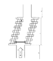
図2に示す光電変換装置においては、i型のアモルファスシリコン層7が、複数の薄膜(7A、7B)よりなり、量子ドットdを含有するi型のアモルファスシリコン薄膜(半導体結晶性微粒子を分散状態で含有する半導体膜)7Aと量子ドットdを含有しないi型のアモルファスシリコン薄膜(半導体膜)7Bが繰り返し積層されている。
In the photoelectric conversion device shown in FIG. 2, the i-type
このように、上記量子ドット型の光電変換装置においては、i型のアモルファスシリコン層7中に量子ドットdを含有させているため、光電変換効率の向上を図ることができる。光電変換効率の向上が図られる理由については、(1)量子サイズ効果、(2)複数エキシトン生成効果および(3)ミニバンド形成効果に起因するものと考えられる。以下、これらについて詳細に説明する。図3は、バルクの場合の複数エキシトン生成効果を説明するためのエネルギーバンド図であり、図4は、量子ドットの場合の複数エキシトン生成効果を説明するためのエネルギーバンド図である。図5は、超格子構造を模式的に示した断面斜視図であり、図6及び図7は、ミニバンドが形成された場合のエネルギーバンド図であり、図8は、ミニバンドが形成されない場合のエネルギーバンド図である。なお、バンド図において黒丸は電子(e)を白丸はホール(h)を示すものとする。
Thus, in the quantum dot photoelectric conversion device, since the quantum dots d are contained in the i-type
(1)量子サイズ効果
光電変換においては、光のエネルギーを吸収した電子(キャリア)が、バンドギャップEgを越えて価電子帯と伝導帯の間を遷移し、電気エネルギー(電力)として取り出される。一般的に、半導体ナノ粒子では粒径が小さくなると、バンドギャップが大きくなることが知られている。これを量子サイズ効果と呼び、これにより、例えば、太陽光スペクトルにおいてエネルギーの大きな紫外光領域、可視光領域や赤外光領域などの特定の波長(例えば、400nm〜800nm)にあわせてバンドギャップを調整することができる。その結果、光を効率良く電気エネルギーに変換することができる。また、バンドギャップの異なる光電変換部を積層することにより、可視光領域や赤外光領域などに限らず太陽光スペクトルの各種波長の光を効率良く電気エネルギーに変換することができる。
(1) Quantum Size Effect In photoelectric conversion, electrons (carriers) that have absorbed light energy transition between the valence band and the conduction band across the band gap Eg, and are extracted as electrical energy (electric power). In general, it is known that in semiconductor nanoparticles, the band gap increases as the particle size decreases. This is called a quantum size effect, and for example, the band gap is adjusted to a specific wavelength (for example, 400 nm to 800 nm) such as an ultraviolet light region, a visible light region, or an infrared light region having a large energy in the sunlight spectrum. Can be adjusted. As a result, light can be efficiently converted into electrical energy. In addition, by stacking photoelectric conversion units having different band gaps, it is possible to efficiently convert light of various wavelengths in the solar spectrum into electric energy, not limited to the visible light region and the infrared light region.
(2)複数エキシトン生成効果(MEG:Multiple Exciton Generation)
図3に示すように、バルクの半導体においては、キャリア(電子)は、光エネルギー(E=hν=hc/λ、h:プランク定数、ν:振動数、c:光の速さ、λ:波長)を受け、価電子帯に遷移し、電気エネルギーとして取り出される。ここで、バンドギャップEgより光エネルギーhνが大きい場合(hν>Eg)、キャリアは価電子帯の上部まで遷移するものの、Egを超えた余分なエネルギーは速やかに格子系に熱として移動して、より安定的な価電子帯の下部まで移動する。つまり、Egを超えたエネルギーは熱として失われる。したがって、1つの光子によって1つのキャリアしか生成できない。なお、励起された電子に対しホールは残存するため、これらの対をエキシトン(exciton、励起子)という。
(2) Multiple Exciton Generation (MEG)
As shown in FIG. 3, in a bulk semiconductor, carriers (electrons) are light energy (E = hν = hc / λ, h: Planck's constant, ν: frequency, c: speed of light, λ: wavelength. ), Transitions to the valence band and is extracted as electrical energy. Here, when the light energy hν is larger than the band gap Eg (hν> Eg), the carrier transitions to the upper part of the valence band, but excess energy exceeding the Eg is quickly transferred to the lattice system as heat, Move to the bottom of the more stable valence band. That is, energy exceeding Eg is lost as heat. Therefore, only one carrier can be generated by one photon. Since holes remain for the excited electrons, these pairs are called excitons.
これに対し、図4に示すように、量子ドットdを用いた場合、量子ドットdのバンドギャップEgとその周囲を取り囲む層(コア-シェル構造の量子ドットdの場合、シェルsが対応する)のバンドギャップEgsとの差(Egs>Eg)により量子井戸が形成される。この量子井戸により電子の移動方向が三次元的に制限される。また、この量子井戸中に形成される電子軌道は連続的ではない。そのため、バンドギャップEgより光エネルギーhνが大きい場合(hν>Eg)に、上位の軌道まで励起された電子が、バンドギャップの上端まで落ちる際に、格子系にエネルギーを熱として与えて緩和する過程が非常に遅くなる。その結果、同じ量子井戸中の別の電子との相互作用が相対的に強くなり、バンドギャップの上端まで落ちる際に別の電子にエネルギーを与える確率が強くなる。この時、当該光エネルギーhνがバンドギャップの2倍より大きい場合(hν>2Eg)には、更なる電子がバンドギャップを超えてエキシトンを生成することができるようになる。よって、1つの光子から複数のキャリア(例えば、電子)を生成することができる。したがって、これらを電流として取り出すことにより光電変換効率を向上させることができる。 On the other hand, as shown in FIG. 4, when the quantum dot d is used, the band gap Eg of the quantum dot d and the surrounding layer (in the case of the quantum dot d having a core-shell structure, the shell s corresponds). The quantum well is formed by the difference (Egs> Eg) from the band gap Egs. This quantum well restricts the direction of electron movement three-dimensionally. Also, the electron orbit formed in this quantum well is not continuous. Therefore, when the light energy hν is larger than the band gap Eg (hν> Eg), when the electrons excited up to the upper orbit fall to the upper end of the band gap, energy is given to the lattice system as heat to relax. Is very slow. As a result, the interaction with another electron in the same quantum well becomes relatively strong, and the probability of giving energy to another electron when falling to the upper end of the band gap becomes strong. At this time, when the light energy hν is larger than twice the band gap (hν> 2Eg), further electrons can generate excitons beyond the band gap. Therefore, a plurality of carriers (for example, electrons) can be generated from one photon. Therefore, photoelectric conversion efficiency can be improved by taking out these as currents.
(3)ミニバンド形成効果
例えば、図5に示すように、量子ドットdを薄膜を介して3次元的に規則正しく配置させる(3次元的な周期性を持たせる)ことにより、量子ドット(量子井戸)間で相互作用が生じ、ミニバンドが形成される。即ち、図6に示すように、トンネル効果により量子井戸間にミニバンドが生じ、励起されたキャリアを、ミニバンドを通じて高速に外部に取り出すことができる。よって、キャリアの再結合による損失を低減でき、光電変換効率を向上させることができる。また、図7に示すように、前述の複数エキシトン生成効果により生じた遷移電子や、ミニバンド間における遷移電子などもミニバンドを介して効率良く取り出すことができる。なお、図7に示すように、電子のみならず、下側の量子井戸中に残存するホールも取り出すことができる。このように、量子ドットに3次元的な周期性を持たせた構造を超格子(SL:supper lattice)又は多重量子井戸(MQW:Multi-Quantum Well)構造という。
(3) Miniband formation effect For example, as shown in FIG. 5, quantum dots (quantum wells) can be formed by regularly arranging quantum dots d through a thin film (having a three-dimensional periodicity). ) To form a miniband. That is, as shown in FIG. 6, a miniband is generated between the quantum wells by the tunnel effect, and excited carriers can be taken out to the outside through the miniband at high speed. Therefore, loss due to carrier recombination can be reduced and photoelectric conversion efficiency can be improved. Further, as shown in FIG. 7, transition electrons generated by the above-described multiple exciton generation effect, transition electrons between minibands, and the like can be efficiently extracted via the minibands. As shown in FIG. 7, not only electrons but also holes remaining in the lower quantum well can be taken out. A structure in which quantum dots are given a three-dimensional periodicity in this way is called a superlattice (SL) or multi-quantum well (MQW) structure.
これに対し、量子ドットdを3次元的にランダムに分散させた場合(例えば、図1参照)は、図8に示すように、量子井戸間のトンネル効果が起こりにくい箇所が存在する。この場合、量子井戸間にミニバンドは形成されない。但し、この場合も、図に示すように、励起された電子は、熱励起などにより量子井戸を超え、量子井戸の外へ抜けることができる。よって、超格子でない場合であっても、確率は低くなるものの量子井戸の外に電子を取り出すことができる。また、図6に示すように、量子ドットdが縦横および上下に規則正しく並んだ構造は理想的ではあるが、量子ドットdをこのように配列させることは容易ではない。よって、図2では、各膜(7A)においては、平面的にランダムに量子ドットdを配列させ、量子ドットdを含まない膜(7B)と交互に配置させることにより、配列の周期性を持たせている。かかる構成によっても、ミニバンドの形成率を向上させ、光電変換効率を向上させることができる。また、図2においては、膜7A中において、量子ドットdを1原子ずつ配列させているが、当該膜中の原子配列において、上下方向に原子が2個又は3個程度配列していてもよい。要は、薄膜(7A、7B)を交互に積層させることにより、配列の周期性を持たせることが重要である。
On the other hand, when the quantum dots d are randomly dispersed three-dimensionally (see, for example, FIG. 1), there are places where the tunnel effect between the quantum wells hardly occurs as shown in FIG. In this case, no miniband is formed between the quantum wells. However, in this case as well, as shown in the figure, the excited electrons can pass through the quantum well by thermal excitation or the like and escape out of the quantum well. Therefore, even if it is not a superlattice, although the probability is low, electrons can be taken out of the quantum well. Also, as shown in FIG. 6, a structure in which quantum dots d are regularly arranged vertically and horizontally and vertically is ideal, but it is not easy to arrange quantum dots d in this way. Therefore, in FIG. 2, in each film (7A), the quantum dots d are arranged randomly in a plane and alternately arranged with the film (7B) not including the quantum dots d, thereby providing the periodicity of the arrangement. It is Such a configuration can also improve the formation rate of the miniband and improve the photoelectric conversion efficiency. In FIG. 2, the quantum dots d are arranged one atom at a time in the
以上(1)〜(3)を通じて詳細に説明したように、量子ドットdを含有させることで光電変換効率の向上を図ることができる。 As described in detail through (1) to (3) above, the photoelectric conversion efficiency can be improved by including the quantum dots d.
(実施の形態)
[装置構成]
本発明の実施の形態による量子ドット型の光電変換装置は、図2に示す光電変換装置と同様の構成を有している。上述したように、図2に示す光電変換装置においては、i型のアモルファスシリコン層7が、複数の薄膜(7A、7B)を有し、量子ドットdを含有するi型のアモルファスシリコン薄膜7Aと量子ドットdを含有しないi型のアモルファスシリコン薄膜7Bが繰り返し積層されている。量子ドットdを含有するi型のアモルファスシリコン薄膜7Aには、ゲルマニウム(Ge)よりなる量子ドットdが分散状態で含有されている。
(Embodiment)
[Device configuration]
The quantum dot photoelectric conversion device according to the embodiment of the present invention has the same configuration as the photoelectric conversion device shown in FIG. As described above, in the photoelectric conversion device shown in FIG. 2, the i-type
[製造方法]
次に、図9を用いて本実施形態による光電変換装置の製造方法について説明する。図9は、本実施の形態の光電変換装置の製造工程を模式的に示す断面図である。
[Production method]
Next, the manufacturing method of the photoelectric conversion device according to the present embodiment will be explained with reference to FIG. FIG. 9 is a cross-sectional view schematically showing the manufacturing process of the photoelectric conversion device of the present embodiment.
まず、図9(A)に示すように、基板1として例えば、石英ガラス基板を準備する。なお、基板1としては、光透過性の石英ガラス基板の他、ソーダガラス基板などの他のガラス基板、ポリカーボネート、ポリエチレンテレフタレートなどの樹脂を用いた樹脂基板やセラミックス基板などを用いてもよい。
First, as shown in FIG. 9A, for example, a quartz glass substrate is prepared as the
次に、図9(B)に示すように、基板1上に透明電極3を形成する。透明電極3は、例えば、フッ素を添加した酸化錫(FTO:F-doped Tin Oxide)膜をCVD法を用いて堆積させることにより形成する。また、この他、インジウムを添加した酸化錫(ITO:Indium Tin Oxide)、酸化インジウム(InO)、酸化錫(SnO2)、酸化亜鉛(ZnO)などの他の導電性の金属酸化物を用いてもよい。このような透明電極を用いることにより、基板1の裏面側(図中下側)からの光の透過性を向上させることができる。
Next, as illustrated in FIG. 9B, the
次に、図9(C)に示すように、透明電極3上に、p型のアモルファスシリコン層5を形成する。p型のアモルファスシリコン層5は、例えば、黄燐を混合したシクロペンタシラン(Si5H10)に紫外線を照射して得られるp型ドープ水素化ポリシランをトルエンに溶かした溶液を、スピンコート法で塗布した後、300℃で焼成することにより形成する。
Next, as shown in FIG. 9C, a p-type
次に、p型のアモルファスシリコン層5上にi型のアモルファスシリコン層7を形成する工程について説明する。
まず、シクロペンタシランに紫外線を照射して得えられる水素化ポリシランをデカヒドロナフタレンに溶かした溶液(液体半導体材料)と、表面をシランカップリング剤などの有機化合物で被覆した結晶性PbS微粒子(第1の半導体結晶性微粒子)をトルエン(第1の有機溶媒)に分散させた溶液を混合した混合溶液(第1の塗布液)を作成する。結晶性PbS微粒子の表面を有機化合物で被覆することにより、有機溶媒(トルエン)に均等に分散させることができる。
Next, a process for forming the i-type
First, a solution (liquid semiconductor material) in which hydrogenated polysilane obtained by irradiating cyclopentasilane with ultraviolet rays is dissolved in decahydronaphthalene, and crystalline PbS fine particles whose surface is coated with an organic compound such as a silane coupling agent ( A mixed solution (first coating solution) is prepared by mixing a solution in which first semiconductor crystalline fine particles) are dispersed in toluene (first organic solvent). By coating the surface of the crystalline PbS fine particles with an organic compound, it can be uniformly dispersed in an organic solvent (toluene).
液体半導体材料には、水素化ポリシラン:デカヒドロナフタレン=1:9の割合で含まれる。また、半導体結晶性微粒子を含む液体には、結晶性PbS微粒子:トルエン=1:9の割合で含まれる。両方の溶液を1:1の割合で混合した混合溶液を、p型のアモルファスシリコン層5上にスピンコート法を用いて塗布し、塗布した混合溶液を乾燥させた後、300℃で焼成(熱処理)し、アモルファス化する。乾燥の過程で、混合溶液が結晶性PbS微粒子を含む層と含まない層に分離される。続いて焼成を行うことにより、図9(D)に示すように、結晶性PbS微粒子を含有するi型のアモルファスシリコン薄膜7Aと結晶性PbS微粒子を含有しないi型のアモルファスシリコン薄膜7Bの2層が形成される。
The liquid semiconductor material contains hydrogenated polysilane: decahydronaphthalene = 1: 9. The liquid containing semiconductor crystalline fine particles is contained in a ratio of crystalline PbS fine particles: toluene = 1: 9. A mixed solution in which both solutions are mixed at a ratio of 1: 1 is applied onto the p-type
混合溶液の塗布、乾燥及び焼成をn回(nは2以上の整数)行うと、図9(E)に示すように、結晶性PbS微粒子を含有するi型のアモルファスシリコン薄膜7Aと結晶性PbS微粒子を含有しないi型のアモルファスシリコン薄膜7Bが交互にn層積層されたi型のアモルファスシリコン層7が得られる。図9(E)に示す例では、混合溶液の塗布、乾燥及び焼成を5回行った。なお、焼成の温度は300℃以上であれば良い。
When the mixed solution is applied, dried, and fired n times (n is an integer of 2 or more), as shown in FIG. 9E, the i-type amorphous silicon
なお、液体半導体材料の水素化ポリシランの濃度によって、形成される2層(アモルファスシリコン薄膜7A、7B)の合計の膜厚を調節することができる。水素化ポリシランの濃度は、有機溶媒に対して5%以上とすることが望ましい。
Note that the total thickness of the two layers (amorphous silicon
また、水素化ポリシラン溶液(液体半導体材料)と結晶性PbS微粒子の分散溶液の混合比によって、アモルファスシリコン薄膜7A、7Bの厚さの比が調節できる。原子数比で、水素化ポリシラン:結晶性PbS微粒子=X:Yとなるように両溶液を混合すると、結晶性PbS微粒子を含有するi型のアモルファスシリコン薄膜7Aの厚さ:結晶性PbS微粒子を含有しないi型のアモルファスシリコン薄膜7Bの厚さは、ほぼY:Xとなる。なお、X≧YかつYはXの10%以上とすることが望ましい。
The thickness ratio of the amorphous silicon
また、水素化ポリシランを溶かす有機溶媒と、半導体結晶性微粒子を分散させる有機溶媒は、沸点の差が20℃以上あることが望ましい。これにより、乾燥の過程で結晶性PbS微粒子を含む層と含まない層が分離し、焼成後、結晶性PbS微粒子を含有するi型のアモルファスシリコン薄膜7Aと結晶性PbS微粒子を含有しないi型のアモルファスシリコン薄膜7Bの2層が確実に形成される。
Further, it is desirable that the difference between the boiling points of the organic solvent for dissolving the hydrogenated polysilane and the organic solvent for dispersing the semiconductor crystalline fine particles is 20 ° C. or more. As a result, a layer containing crystalline PbS fine particles and a layer not containing crystalline PbS fine particles are separated during drying, and after firing, an i-type amorphous silicon
また、第1層から第n層まで全て同じ大きさの半導体結晶性微粒子を用いても良いが、層によって、大きさの異なる半導体結晶性微粒子(第2の半導体結晶性微粒子)を使用してもよい。この場合半導体結晶性微粒子の種類は同じでも良いし変えても良い。一般的に、半導体結晶性微粒子は粒径が小さくなると、バンドギャップが大きくなることが知られている。よって、様々な大きさの半導体結晶性微粒子を分散させた層を積層することにより、様々な波長の光の光電変換が可能な層が積層され、各種波長の光を効率良く電気エネルギーに変換することができるようになる。なお、バンドギャップがより小さい半導体結晶性微粒子を含む層を透明電極3側から順に積層させることが望ましい。
以上に説明した手順で、i型のアモルファスシリコン層7が形成される。
Further, semiconductor crystalline fine particles having the same size from the first layer to the n-th layer may be used, but semiconductor crystalline fine particles having different sizes (second semiconductor crystalline fine particles) are used depending on the layer. Also good. In this case, the type of semiconductor crystalline fine particles may be the same or different. In general, it is known that semiconductor crystalline fine particles have a large band gap when the particle size is small. Therefore, by laminating layers in which semiconductor crystalline fine particles of various sizes are dispersed, layers capable of photoelectric conversion of light of various wavelengths are laminated, and light of various wavelengths is efficiently converted into electrical energy. Will be able to. Note that it is desirable to sequentially stack layers including semiconductor crystalline fine particles having a smaller band gap from the
The i-type
次に、図9(F)に示すように、i型のアモルファスシリコン層7上にn型のアモルファスシリコン層9を形成する。n型のアモルファスシリコン層9は、例えば、ホウ素化合物であるデカボランを混合したシクロペンタシランに紫外線を照射して得られるn型ドープ水素化ポリシランをトルエンに溶かした溶液を、スピンコート法で塗布した後、300℃で焼成することにより形成する。
Next, as shown in FIG. 9F, an n-type
次に、図9(G)に示すように、n型のアモルファスシリコン層9上に、金属電極11としてAl膜を形成する。例えば、n型のアモルファスシリコン層9上に、Alをスパッタリング法により堆積し、必要に応じてパターニングすることにより金属電極11を形成する。以上の工程により、本実施の形態の光電変換装置が形成される。
Next, as shown in FIG. 9G, an Al film is formed as a
なお、本実施の形態においては、シクロペンタシランに紫外線を照射して得られる重合体(水素化ポリシラン)をデカヒドロナフタレンに溶かすことにより、液体半導体材料を得たが、シクロペンタシラン以外の、他のケイ素化合物の重合体を用いても良い。ケイ素化合物としては、SinXmで表されるケイ素化合物を用いることができる。m=2n+2である化合物の具体例としては、トリシラン、テトラシラン、ペンタシラン、ヘキサシラン、ヘプタシランなどの水素化シラン、またこれらの水素原子の一部またはすべてをハロゲン原子に置換したものが挙げられる。m=2nである具体例としては、シクロトリシラン、シクロテトラシラン、上述のシクロペンタシラン、シリルシクロペンタシラン、シクロヘキサシラン、シリルシクロヘキサシラン、シクロヘプタシラン、などの一個の環系を有する水素化ケイ素化合物およびこれらの水素原子の一部またはすべてをハロゲン原子に置換したヘキサクロルシクロトリシラン、トリクロルシクロトリシラン、オクタクロルシクロテトラシラン、テトラクロルシクロテトラシラン、デカクロルシクロペンタシラン、ペンタクロルシクロペンタシラン、ドデカクロルシクロヘキサシラン、ヘキサクロルシクロヘキサシラン、テトラデカクロルシクロヘプタシラン、ヘプタクロルシクロヘプタシラン、ヘキサブロモシクロトリシラン、トリブロモシクロトリシラン、ペンタブロモシクロトリシラン、テトラブロモシクロトリシラン、オクタブロモシクロテトラシラン、テトラブロモシクロテトラシラン、デカブロモシクロペンタシラン、ペンタブロモシクロペンタシラン、ドデカブロモシクロヘキサシラン、ヘキサブロモシクロヘキサシラン、テトラデカブロモシクロヘプタシラン、ヘプタブロモシクロヘプタシランなどのハロゲン化環状ケイ素化合物が挙げられる。m=2n−2である化合物の具体例としては、1、1'−ビスシクロブタシラン、1、1'−ビスシクロペンタシラン、1、1'−ビスシクロヘキサシラン、1、1'−ビスシクロヘプタシラン、1、1'−シクロブタシリルシクロペンタシラン、1、1'−シクロブタシリルシクロヘキサシラン、1、1'−シクロブタシリルシクロヘプタシラン、1、1'−シクロペンタシリルシクロヘキサシラン、1、1'−シクロペンタシリルシクロヘプタシラン、1、1'−シクロヘキサシリルシクロヘプタシラン、スピロ[2、2]ペンタシラン、スピロ[3、3]ヘプタタシラン、スピロ[4、4]ノナシラン、スピロ[4、5]デカシラン、スピロ[4、6]ウンデカシラン、スピロ[5、5]ウンデカシラン、スピロ[5、6]ドデカシラン、スピロ[6、6]トリデカシランなどの2個の環系を有する水素化ケイ素化合物およびこれらの水素原子の一部またはすべてをSiH3基やハロゲン原子に置換したケイ素化合物が挙げられる。また、m=nである化合物や、これらの水素原子の一部またはすべてを部分的にSiH3基やハロゲン原子に置換したケイ素化合物、また、一般式SiaXbYcで表わされるケイ素化合物を用いてもよい。これらの化合物は2種以上を混合して使用することができる。また、重合に際しては、上記紫外線の他、熱や他のエネルギー線を用いてもよい。 In the present embodiment, a liquid semiconductor material was obtained by dissolving a polymer (hydrogenated polysilane) obtained by irradiating cyclopentasilane with ultraviolet rays in decahydronaphthalene, but other than cyclopentasilane, Other silicon compound polymers may be used. As the silicon compound, a silicon compound represented by Si n X m can be used. Specific examples of the compound in which m = 2n + 2 include hydrogenated silanes such as trisilane, tetrasilane, pentasilane, hexasilane, and heptasilane, and those obtained by substituting some or all of these hydrogen atoms with halogen atoms. Specific examples of m = 2n include one ring system such as cyclotrisilane, cyclotetrasilane, the above-mentioned cyclopentasilane, silylcyclopentasilane, cyclohexasilane, silylcyclohexasilane, and cycloheptasilane. Silicon hydride compounds and hexachlorocyclotrisilane, trichlorocyclotrisilane, octachlorocyclotetrasilane, tetrachlorocyclotetrasilane, decachlorocyclopentasilane, pentane in which some or all of these hydrogen atoms are substituted with halogen atoms Chlorocyclopentasilane, dodecachlorocyclohexasilane, hexachlorocyclohexasilane, tetradecachlorocycloheptasilane, heptachlorocycloheptasilane, hexabromocyclotrisilane, tribromocyclotrisilane, Interbromocyclotrisilane, tetrabromocyclotrisilane, octabromocyclotetrasilane, tetrabromocyclotetrasilane, decabromocyclopentasilane, pentabromocyclopentasilane, dodecabromocyclohexasilane, hexabromocyclohexasilane, tetradeca Examples thereof include halogenated cyclic silicon compounds such as bromocycloheptasilane and heptabromocycloheptasilane. Specific examples of the compound in which m = 2n-2 include 1,1′-biscyclobutasilane, 1,1′-biscyclopentasilane, 1,1′-biscyclohexasilane, 1,1′-bis. Cycloheptasilane, 1,1′-cyclobutasilylcyclopentasilane, 1,1′-cyclobutasilylcyclohexasilane, 1,1′-cyclobutasilylcycloheptasilane, 1,1′-cyclopentasilylcyclohexasilane Lan, 1,1′-cyclopentasilylcycloheptasilane, 1,1′-cyclohexasilylcycloheptasilane, spiro [2,2] pentasilane, spiro [3,3] heptatasilane, spiro [4,4] nonasilane, Spiro [4,5] decasilane, spiro [4,6] undecasilane, spiro [5,5] undecasilane, spiro [5,6] dodecasilane, spiro [6 6] Silicon hydride compounds having two ring systems such as tridecasilane, and silicon compounds in which some or all of these hydrogen atoms are substituted with SiH 3 groups or halogen atoms. Further, compounds in which m = n, silicon compounds in which some or all of these hydrogen atoms are partially substituted with SiH 3 groups or halogen atoms, and silicon compounds represented by the general formula Si a X b Y c May be used. These compounds can be used in combination of two or more. In the polymerization, in addition to the ultraviolet rays, heat or other energy rays may be used.
また、水素化ポリシランを溶かす溶媒としては、デカヒドロナフタレン以外にも、ケイ素化合物を溶解するものであれば特に限定されない。具体例として、n−ヘキサン、n−ヘプタン、n−オクタン、n−デカン、ジシクロペンタン、シクロヘキサン、シクロオクタン、ベンゼン、トルエン、キシレン、デュレン、インデン、テトラヒドロナフタレン、デカヒドロナフタレン、スクワランなどの炭化水素系溶媒の他、ジプロピルエーテル、エチレングリコールジメチルエーテル、エチレングリコールジエチルエーテル、エチレングリコールメチルエチルエーテル、ジエチレングリコールジメチルエーテル、ジエチレングリコールジエチルエーテル、ジエチレングリコールメチルエチルエーテル、テトラヒドロフラン、テトラヒドロピラン、1,2−ジメトキシエタン、ビス(2−メトキシエチル)エーテル、p−ジオキサンなどのエーテル系溶媒、さらにプロピレンカーボネート、γ−ブチロラクトン、N−メチル−2−ピロリドン、ジメチルホルムアミド、アセトニトリル、ジメチルスルホキシド、クロロホルムなどの極性溶媒が挙げられる。また、SinXmで表される化合物で、m=2n+2(mは3以上の整数)のものが挙げられる。具体例はトリシラン、テトラシラン、ペンタシランなどである。また、SinXmで表され、m=2n(mは3以上の整数)の環状シラン化合物が挙げられる。具体例としては、シクロトリシラン、シクロテトラシラン、シクロペンタシランなど液体の低級シラン化合物を挙げることができる。これらのうち、ケイ素化合物及び変性ケイ素化合物の溶解性と、溶液の安定性の点で、炭化水素系溶媒、エーテル系溶媒が好ましく、さらに好ましい溶媒としては炭化水素系溶媒を挙げることができる。これらの溶媒は、単独でも、或いは2種以上を混合しても使用できる。特に炭化水素系溶媒は、ケイ素化合物の溶解性が高く、熱処理時のケイ素化合物の残留を抑制する効果がある。 In addition to decahydronaphthalene, the solvent for dissolving hydrogenated polysilane is not particularly limited as long as it dissolves a silicon compound. Specific examples include carbonization of n-hexane, n-heptane, n-octane, n-decane, dicyclopentane, cyclohexane, cyclooctane, benzene, toluene, xylene, durene, indene, tetrahydronaphthalene, decahydronaphthalene, squalane and the like. In addition to hydrogen solvents, dipropyl ether, ethylene glycol dimethyl ether, ethylene glycol diethyl ether, ethylene glycol methyl ethyl ether, diethylene glycol dimethyl ether, diethylene glycol diethyl ether, diethylene glycol methyl ethyl ether, tetrahydrofuran, tetrahydropyran, 1,2-dimethoxyethane, bis Ether solvents such as (2-methoxyethyl) ether and p-dioxane, and further propylene carbonate γ- butyrolactone, N- methyl-2-pyrrolidone, dimethylformamide, acetonitrile, dimethylsulfoxide, polar solvents such as chloroform. Moreover, it is a compound represented by Si n X m , and m = 2n + 2 (m is an integer of 3 or more). Specific examples are trisilane, tetrasilane, pentasilane and the like. Further, a cyclic silane compound represented by Si n X m and m = 2n (m is an integer of 3 or more) can be used. Specific examples include liquid lower silane compounds such as cyclotrisilane, cyclotetrasilane, and cyclopentasilane. Of these, hydrocarbon solvents and ether solvents are preferred in view of the solubility of the silicon compound and the modified silicon compound and the stability of the solution, and more preferred solvents include hydrocarbon solvents. These solvents can be used alone or in admixture of two or more. In particular, a hydrocarbon solvent has a high solubility of a silicon compound, and has an effect of suppressing residual silicon compound during heat treatment.
また、半導体結晶性微粒子としては、結晶性PbS微粒子の他、例えば、CdSe、CdTe、CdS、InAs、GaAs、GaN、InAsP、GaInP、GaNAs、Ge、Siなどを用いることができる。これらの材料は単独でも、或いは2種類以上を混合しても使用できる。 In addition to the crystalline PbS fine particles, for example, CdSe, CdTe, CdS, InAs, GaAs, GaN, InAsP, GaInP, GANAS, Ge, Si and the like can be used as the semiconductor crystalline fine particles. These materials can be used alone or in combination of two or more.
また、n型のアモルファスシリコン層9を形成するのに用いるn型のドープ材料は、本実施の形態ではデカボランを使用したが、その他に、ジボラン、ペンタボラン、ヘキサボランなどの水素化ホウ素化合物や3族元素を含む化合物を使うことができる。
Further, in this embodiment, decaborane is used as the n-type dope material used to form the n-type
また、p型のアモルファスシリコン層5を形成するのに用いるp型のドープ材料は、本実施の形態では黄燐を使用したが、その他、リンの同素体やリンを含む化合物、4族元素を含む化合物を使うことができる。
The p-type doped material used to form the p-type
なお、i型のアモルファスシリコン層7の膜厚は、100nm〜700nmであることが望ましい。これにより、光が光電変換層を通過してしまったり、光電変換層全体に入射しなかったりすることを防止できる。
The film thickness of the i-type
以上のように、本実施の形態によれば、i型のアモルファスシリコン層7を形成する際、水素化ポリシランをデカヒドロナフタレンに溶かした溶液(液体半導体材料)と、結晶性PbS微粒子(第1の半導体結晶性微粒子)をトルエン(第1の有機溶媒)に分散させた溶液の混合溶液(第1の塗布液)を、p型のアモルファスシリコン層5上に塗布して乾燥させた後、焼成することにより、結晶性PbS微粒子を含有するi型のアモルファスシリコン薄膜7Aと結晶性PbS微粒子を含有しないi型のアモルファスシリコン薄膜7Bの2層を形成した。
As described above, according to the present embodiment, when the i-type
これにより、混合溶液の1度の塗布、乾燥及び焼成で、結晶性PbS微粒子を含有するi型のアモルファスシリコン薄膜7Aと結晶性PbS微粒子を含有しないi型のアモルファスシリコン薄膜7Bの2層を形成できるので、製造にかかる時間とコストを低減することができる。また、CVD装置やパターニングのためのフォトリソグラフィー、レーザーエッチング装置等を必要とせず、アモルファスシリコン膜中に結晶性PbS微粒子を分散させるための高温装置も使用しないため、低エネルギーで膜を形成できる。また、液体材料の塗布によって膜を形成するため、エッチングでパターニングする場合のように材料の無駄な廃棄が生じない。さらに、結晶性PbS微粒子を含有するアモルファスシリコン膜が含まれることから、光電変換効率が高い光電変換装置が得られる。
As a result, two layers of an i-type amorphous silicon
また、混合溶液の塗布、乾燥及び焼成をn回(nは2以上の整数)行うことにより、結晶性PbS微粒子を含有するi型のアモルファスシリコン薄膜7Aと結晶性PbS微粒子を含有しないi型のアモルファスシリコン薄膜7Bが交互にn層積層されたi型のアモルファスシリコン層7が得られ、より光電変換効率が高い光電変換装置が高い製造効率で得られる。
Further, by applying the mixed solution, drying and firing n times (n is an integer of 2 or more), the i-type amorphous silicon
また、様々な大きさの半導体結晶性微粒子を分散させたアモルファスシリコン膜を積層することにより、様々な波長の光の光電変換が可能な層が積層され、各種波長の光を効率良く電気エネルギーに変換することができるようになる。 In addition, by laminating amorphous silicon films in which semiconductor crystalline fine particles of various sizes are dispersed, layers capable of photoelectric conversion of light of various wavelengths are laminated, and light of various wavelengths is efficiently converted into electrical energy. Can be converted.
<電子機器>
上記の光電変換装置は、各種電子機器に組み込むことができる。適用できる電子機器に制限はないがその一例について説明する。
<Electronic equipment>
The photoelectric conversion device can be incorporated into various electronic devices. There is no limitation on applicable electronic devices, but an example thereof will be described.
図10は、本発明の光電変換装置を適用した電卓を示す平面図、図11は、本発明の光電変換装置を適用した携帯電話機(PHSも含む)を示す斜視図である。 FIG. 10 is a plan view showing a calculator to which the photoelectric conversion device of the present invention is applied, and FIG. 11 is a perspective view showing a mobile phone (including PHS) to which the photoelectric conversion device of the present invention is applied.
図10に示す電卓100は、本体部101と、本体部101の上面(前面)に設けられた表示部102、複数の操作ボタン103および光電変換素子設置部104とを備えている。
A
図10に示す構成では、光電変換素子設置部104には、光電変換素子1が5つ直列に接続されて配置されている。この光電変換素子1として上記光電変換装置を組み込むことができる。
In the configuration shown in FIG. 10, five
図11に示す携帯電話機200は、本体部201と、本体部201の前面に設けられた表示部202、複数の操作ボタン203、受話口204、送話口205および光電変換素子設置部206とを備えている。
A
図11に示す構成では、光電変換素子設置部206が、表示部202の周囲を囲むようにして設けられ、光電変換素子1が複数、直列に接続されて配置されている。この光電変換素子1として上記光電変換装置を組み込むことができる。
In the configuration illustrated in FIG. 11, the photoelectric conversion
なお、本発明の電子機器としては、図10に示す電卓、図11に示す携帯電話機の他、例えば、光センサー、光スイッチ、電子手帳、電子辞書、腕時計、クロック等に適用することもできる。 Note that the electronic device of the present invention can be applied to, for example, an optical sensor, an optical switch, an electronic notebook, an electronic dictionary, a wristwatch, a clock, and the like in addition to the calculator shown in FIG. 10 and the mobile phone shown in FIG.
図12は、電子機器の一例である腕時計を示す斜視図である。この腕時計1100は、表示部1101を備え、例えば、この表示部1101の外周に、上記光電変換装置を組み込むことができる。
FIG. 12 is a perspective view illustrating a wrist watch that is an example of an electronic apparatus. The
また、上記光電変換装置は、低コスト化、量産化に適し、家庭用又は業務用の太陽光発電システムに用いても好適である。 The photoelectric conversion device is suitable for cost reduction and mass production, and is also suitable for use in a solar power generation system for home use or business use.
なお、上記実施の形態を通じて説明された実施例や応用例は、用途に応じて適宜に組み合わせて、又は変更若しくは改良を加えて用いることができ、本発明は上述した実施の形態の記載に限定されるものではない。 It should be noted that the examples and application examples described through the above embodiment can be used in appropriate combination according to the application, or can be used with modifications or improvements, and the present invention is limited to the description of the above embodiment. Is not to be done.
1 基板、3 透明電極、5 p型のアモルファスシリコン層、7 i型のアモルファスシリコン層、9 n型のアモルファスシリコン層、11 上部電極、7A 量子ドットdを含有するi型のアモルファスシリコン薄膜、7B 量子ドットdを含有しないi型のアモルファスシリコン薄膜、100 電卓、101 本体部、102 表示部、103 操作ボタン、104 光電変換素子設置部、200 携帯電話機、201 本体部、202 表示部、203 操作ボタン、204 受話口、205 送話口、206 光電変換素子設置部、1100 腕時計、1101 表示部、d 量子ドット 1 substrate, 3 transparent electrode, 5 p-type amorphous silicon layer, 7 i-type amorphous silicon layer, 9 n-type amorphous silicon layer, 11 upper electrode, 7A i-type amorphous silicon thin film containing quantum dots d, 7B I-type amorphous silicon thin film not containing quantum dots d, 100 calculator, 101 main body, 102 display, 103 operation buttons, 104 photoelectric conversion element installation, 200 mobile phone, 201 main body, 202 display, 203 operation buttons , 204 Earpiece, 205 Mouthpiece, 206 Photoelectric conversion element installation unit, 1100 wristwatch, 1101 display unit, d quantum dot
Claims (14)
前記光電変換層の形成工程が、
液体半導体材料及び第1の半導体結晶性微粒子を含む、第1の塗布液を作成する第1工程と、
前記第1の塗布液を塗布する第2工程と、
前記第1の塗布液を乾燥させ、第1の乾燥膜を形成する第3工程と、
前記第1の乾燥膜に熱処理を施す第4工程と、
を含む光電変換装置の製造方法。 A method for producing a photoelectric conversion device having a photoelectric conversion layer,
The step of forming the photoelectric conversion layer comprises:
A first step of creating a first coating liquid comprising a liquid semiconductor material and first semiconductor crystalline fine particles;
A second step of applying the first coating liquid;
A third step of drying the first coating solution to form a first dry film;
A fourth step of applying a heat treatment to the first dry film;
The manufacturing method of the photoelectric conversion apparatus containing this.
を特徴とする請求項1から請求項3のいずれか一項に記載の光電変換装置の製造方法。 The first semiconductor crystalline fine particles are coated with an organic compound;
The manufacturing method of the photoelectric conversion apparatus as described in any one of Claims 1-3 characterized by these.
前記第2の塗布液を塗布する第6工程と、
前記第2の塗布液を乾燥させ、第2の乾燥膜を形成する第7工程と、
前記第2の乾燥膜に熱処理を施す第8工程と、
を含み、
前記第2工程、前記第3工程及び前記第4工程を行った後、前記第6工程、前記第7工程及び前記第8工程を行うこと、を特徴とする請求項1から請求項6のいずれか一項に記載の光電変換装置の製造方法。 A fifth step of creating a second coating liquid containing the liquid semiconductor material and the second semiconductor crystalline fine particles;
A sixth step of applying the second coating solution;
A seventh step of drying the second coating solution to form a second dry film;
An eighth step of applying a heat treatment to the second dry film;
Including
7. The method according to claim 1, wherein the sixth step, the seventh step, and the eighth step are performed after performing the second step, the third step, and the fourth step. A method for producing the photoelectric conversion device according to claim 1.
Priority Applications (1)
| Application Number | Priority Date | Filing Date | Title |
|---|---|---|---|
| JP2009106066A JP2010258194A (en) | 2009-04-24 | 2009-04-24 | Method for manufacturing photoelectric conversion device |
Applications Claiming Priority (1)
| Application Number | Priority Date | Filing Date | Title |
|---|---|---|---|
| JP2009106066A JP2010258194A (en) | 2009-04-24 | 2009-04-24 | Method for manufacturing photoelectric conversion device |
Publications (1)
| Publication Number | Publication Date |
|---|---|
| JP2010258194A true JP2010258194A (en) | 2010-11-11 |
Family
ID=43318769
Family Applications (1)
| Application Number | Title | Priority Date | Filing Date |
|---|---|---|---|
| JP2009106066A Pending JP2010258194A (en) | 2009-04-24 | 2009-04-24 | Method for manufacturing photoelectric conversion device |
Country Status (1)
| Country | Link |
|---|---|
| JP (1) | JP2010258194A (en) |
Cited By (5)
| Publication number | Priority date | Publication date | Assignee | Title |
|---|---|---|---|---|
| WO2012114624A1 (en) * | 2011-02-21 | 2012-08-30 | パナソニック株式会社 | Quantum dot semiconductor film and method of forming the same |
| JP2012235071A (en) * | 2011-05-09 | 2012-11-29 | Sharp Corp | Solar cell |
| JP2013021203A (en) * | 2011-07-13 | 2013-01-31 | Tohoku Univ | Solar cell and method for manufacturing solar cell |
| JP2013122955A (en) * | 2011-12-09 | 2013-06-20 | Sharp Corp | Compound semiconductor layer, manufacturing method of the same, compound thin film solar cell and manufacturing method of the same |
| WO2019058448A1 (en) | 2017-09-20 | 2019-03-28 | 花王株式会社 | Light absorption layer, method of manufacturing same, dispersion liquid, photoelectric conversion element, and intermediate band-type solar cell |
-
2009
- 2009-04-24 JP JP2009106066A patent/JP2010258194A/en active Pending
Cited By (5)
| Publication number | Priority date | Publication date | Assignee | Title |
|---|---|---|---|---|
| WO2012114624A1 (en) * | 2011-02-21 | 2012-08-30 | パナソニック株式会社 | Quantum dot semiconductor film and method of forming the same |
| JP2012235071A (en) * | 2011-05-09 | 2012-11-29 | Sharp Corp | Solar cell |
| JP2013021203A (en) * | 2011-07-13 | 2013-01-31 | Tohoku Univ | Solar cell and method for manufacturing solar cell |
| JP2013122955A (en) * | 2011-12-09 | 2013-06-20 | Sharp Corp | Compound semiconductor layer, manufacturing method of the same, compound thin film solar cell and manufacturing method of the same |
| WO2019058448A1 (en) | 2017-09-20 | 2019-03-28 | 花王株式会社 | Light absorption layer, method of manufacturing same, dispersion liquid, photoelectric conversion element, and intermediate band-type solar cell |
Similar Documents
| Publication | Publication Date | Title |
|---|---|---|
| JP5423952B2 (en) | Photoelectric conversion device and electronic device | |
| Li et al. | High performance photodetector based on 2D CH3NH3PbI3 perovskite nanosheets | |
| Dutta et al. | High efficiency hybrid solar cells using nanocrystalline Si quantum dots and Si nanowires | |
| Chatterjee et al. | p–i–n Heterojunctions with BiFeO3 Perovskite Nanoparticles and p-and n-Type Oxides: Photovoltaic Properties | |
| Saadi et al. | Recent developments and applications of nanocomposites in solar cells: a review | |
| Di Carlo et al. | Two-dimensional materials in perovskite solar cells | |
| US20090071539A1 (en) | Solar cell manufactured using amorphous and nanocrystalline silicon composite thin film, and process for manufacturing the same | |
| JP2010067801A (en) | Photoelectric conversion device, electronic apparatus, method for manufacturing photoelectric conversion device, and method for manufacturing electronic apparatus | |
| JP2010067802A (en) | Photoelectric conversion device, electronic apparatus, method for manufacturing photoelectric conversion device, and method for manufacturing electronic apparatus | |
| US20110203650A1 (en) | Optical converter device and electronic equipment including the optical converter device | |
| Zhou et al. | Emerging frontiers of 2D transition metal dichalcogenides in photovoltaics solar cell | |
| CN103000742A (en) | Solar battery with band gap gradual changing silicon quantum dot multilayer film and production method thereof | |
| JP2010067803A (en) | Photoelectric conversion device, electronic apparatus, method for manufacturing photoelectric conversion device, and method for manufacturing electronic apparatus | |
| JP2010118491A (en) | Photoelectric conversion device, and electronic apparatus | |
| JP2010258194A (en) | Method for manufacturing photoelectric conversion device | |
| Mehrabian et al. | Solid-state ZnS quantum dot-sensitized solar cell fabricated by the Dip-SILAR technique | |
| Chen et al. | Three-dimensional radial junction solar cell based on ordered silicon nanowires | |
| JP2010129579A (en) | Method of manufacturing photoelectric conversion device, and method of manufacturing electronic instrument | |
| Khan et al. | Efficiency of thin film photovoltaic paint: A brief review | |
| Mali et al. | Stability of unstable perovskites: recent strategies for making stable perovskite solar cells | |
| JP5880629B2 (en) | Photoelectric conversion device, electronic device, method for manufacturing photoelectric conversion device, and method for manufacturing electronic device | |
| JP2010206061A (en) | Method of manufacturing photoelectric converter and method of manufacturing electronic equipment | |
| JP2011187646A (en) | Optical converter and electronic apparatus including the same | |
| JP2010103335A (en) | Method for manufacturing photoelectric conversion device, method for manufacturing electronic apparatus, photoelectric conversion device and electronic apparatus | |
| Beepat et al. | Perovskite materials for photovoltaics: a review |