JP2010245265A - Thermoelectric module - Google Patents
Thermoelectric module Download PDFInfo
- Publication number
- JP2010245265A JP2010245265A JP2009092064A JP2009092064A JP2010245265A JP 2010245265 A JP2010245265 A JP 2010245265A JP 2009092064 A JP2009092064 A JP 2009092064A JP 2009092064 A JP2009092064 A JP 2009092064A JP 2010245265 A JP2010245265 A JP 2010245265A
- Authority
- JP
- Japan
- Prior art keywords
- substrate
- thermoelectric
- electrode
- heat exchanger
- temperature side
- Prior art date
- Legal status (The legal status is an assumption and is not a legal conclusion. Google has not performed a legal analysis and makes no representation as to the accuracy of the status listed.)
- Pending
Links
Images


Landscapes
- Cooling Or The Like Of Semiconductors Or Solid State Devices (AREA)
Abstract
Description
本発明は、自動車の排気ガスから得られる排熱を利用した熱電発電装置に係り、特に、熱電発電装置を構成する熱電モジュールの電極構造に関する。 The present invention relates to a thermoelectric power generation apparatus using exhaust heat obtained from automobile exhaust gas, and more particularly to an electrode structure of a thermoelectric module constituting the thermoelectric power generation apparatus.
従来、n型半導体とp型半導体を用い、電極板を介して直列に接合した熱電素子が知られている。この熱電素子は、熱源と冷却手段のそれぞれに接触して、熱電素子に生じた温度差によって起電力が生じるゼーベック効果を利用したものであり、この熱電素子を応用して内燃機関の排気ガスの熱エネルギーを電気エネルギーとして回収する熱電発電装置が開示されている(例えば、特許文献1〜3参照)。 Conventionally, a thermoelectric element using an n-type semiconductor and a p-type semiconductor and joined in series via an electrode plate is known. This thermoelectric element utilizes the Seebeck effect in which an electromotive force is generated due to a temperature difference generated in the thermoelectric element in contact with each of the heat source and the cooling means. The thermoelectric element is applied to the exhaust gas of the internal combustion engine. A thermoelectric generator that recovers thermal energy as electrical energy has been disclosed (see, for example, Patent Documents 1 to 3).
このような熱電発電装置では、高温の自動車排気ガスが流通する排気管を熱源(高温側熱交換器)として熱電素子の高温側端面を接触させるとともに、内燃機関の冷却水を循環させる冷却水配管を冷却手段(低温側熱交換器)として熱電素子の低温側端面を接触させることによって温度差を生じさせ、発電を行っている。 In such a thermoelectric generator, an exhaust pipe through which high-temperature automobile exhaust gas flows is used as a heat source (high-temperature side heat exchanger) to contact the high-temperature side end surface of the thermoelectric element and to circulate the cooling water of the internal combustion engine As a cooling means (low temperature side heat exchanger), a temperature difference is produced by bringing the low temperature side end face of the thermoelectric element into contact with each other to generate power.
特許文献1〜3に開示されているように、熱電素子はn型半導体とp型半導体では発生する起電力の向きが逆であるため、これらを交互に直列に接合することで複数の熱電素子からなる熱電素子モジュールとし、複数の熱電素子に発生する起電力を合成して取り出すことができる。 As disclosed in Patent Documents 1 to 3, since the direction of the electromotive force generated in the n-type semiconductor and the p-type semiconductor is opposite in the thermoelectric element, a plurality of thermoelectric elements can be obtained by alternately joining them in series. Thus, the electromotive force generated in a plurality of thermoelectric elements can be synthesized and taken out.
このような従来の熱電モジュールは、セラミック基板によって熱電モジュールの上下を挟み、さらにその上下から高温側・低温側熱交換器で挟んで加熱・冷却し、温度差をつけているので、基板の熱膨張差によりひずみが発生し、素子、または基板の耐久性に課題があった。また、大型のモジュールは、ひずみ量がより大きくなるため、素子や基板に実現可能な強度を持たせたとしても、小型のものしか成立しない。さらに、熱電モジュールを用いて電力を発生させるためには、熱電モジュールに熱を効率的に熱を与えるための熱交換器が必要となるが、フィン等の熱交換器構成部品を直接基板につけることが困難なため、別体の熱交換器を用意し、熱交換器をモジュールに押し当てる必要がある。別体構造は、熱交換器の熱が熱電モジュールに効率的に伝わらない等、多くの問題が存在し、熱電モジュールの性能を十分に生かしきれない。 In such a conventional thermoelectric module, the upper and lower sides of the thermoelectric module are sandwiched between ceramic substrates, and further heated and cooled by sandwiching them between the upper and lower sides with a high-temperature side / low-temperature side heat exchanger. Distortion occurred due to the difference in expansion, and there was a problem with the durability of the element or the substrate. In addition, since a large module has a larger strain amount, only a small module can be formed even if the element or the substrate has a realizable strength. Furthermore, in order to generate electric power using a thermoelectric module, a heat exchanger for efficiently applying heat to the thermoelectric module is required, but heat exchanger components such as fins are directly attached to the substrate. Therefore, it is necessary to prepare a separate heat exchanger and press the heat exchanger against the module. The separate structure has many problems such as the heat of the heat exchanger not being efficiently transferred to the thermoelectric module, and the performance of the thermoelectric module cannot be fully utilized.
従来の熱電発電装置においては、装置の耐久性や、発電効率の向上等を目指して、その構造については種々の検討がなされている。その例として、例えば、複数の熱電素子を接合する接続電極が、熱電素子側から順に金属板−絶縁層−金属箔の3層構造からなるものや、金属層−絶縁層−金属層の3層構造からなるもの等が開示されている(例えば、特許文献4参照)。これらの3層は、接着剤やロウ付けにより接合されている。 In a conventional thermoelectric power generation device, various studies have been made on its structure with the aim of improving the durability of the device and the power generation efficiency. For example, the connection electrode for joining a plurality of thermoelectric elements has a three-layer structure of metal plate-insulating layer-metal foil in order from the thermoelectric element side, or three layers of metal layer-insulating layer-metal layer. What consists of structure etc. is disclosed (for example, refer patent document 4). These three layers are joined by an adhesive or brazing.
しかしながら、上記接続電極において一方の面に金属板、他方の面に金属箔を接着剤で接着した構造を有する場合は、耐熱性、接着強度が十分でないという問題がある。また、これをロウ材で接合した場合は、絶縁層の両面での部材の線膨張応力が異なるため、各部材が冷めたときに、金属板側が凹、金属箔側が凸という具合に反り返ってしまう。さらに、絶縁層の両面にメタライズのような金属層を形成した場合には、金属層と基板とをロウ付けにて接合した後に、絶縁層が反ってしまう。また、熱電発電装置の稼動時/非稼動時の繰り返し応力により、反りが繰り返し発生して、耐久性が低下するという課題がある。 However, when the connection electrode has a structure in which a metal plate is bonded to one surface and a metal foil is bonded to the other surface with an adhesive, there is a problem that heat resistance and adhesive strength are not sufficient. In addition, when this is joined with a brazing material, the linear expansion stress of the members on both sides of the insulating layer is different, so when each member is cooled, the metal plate side is concave and the metal foil side is convex. . Furthermore, when metal layers such as metallization are formed on both surfaces of the insulating layer, the insulating layer warps after the metal layer and the substrate are joined by brazing. Further, there is a problem that warpage is repeatedly generated due to repetitive stress during operation / non-operation of the thermoelectric generator and durability is lowered.
このような絶縁層を有する接続電極の反りを抑制することを目指した熱電発電装置の例としては、排気管の上下面に複数の熱電素子からなる熱電モジュールを配置し、さらに冷却水を循環させる冷却ジャケットによって上下から挟み込むようにして保持し、ナットの締め付けにより上下の冷却ジャケットで熱電素子4を挟み込むようにして固定するものが開示されている(例えば、特許文献5参照)。このように物理的に締め付けることによって、絶縁層を有する接続電極の反りによる変形を抑制している。 As an example of a thermoelectric power generation device aiming at suppressing warpage of the connection electrode having such an insulating layer, a thermoelectric module composed of a plurality of thermoelectric elements is arranged on the upper and lower surfaces of the exhaust pipe, and cooling water is circulated. A device is disclosed that is held by being sandwiched from above and below by a cooling jacket, and is fixed by sandwiching a thermoelectric element 4 between the upper and lower cooling jackets by tightening a nut (see, for example, Patent Document 5). By physically tightening in this way, deformation due to warping of the connection electrode having the insulating layer is suppressed.
しかしながら、ナットによって固定をすると、以下の二つの理由により、熱源からの熱が伝わりづらいため、発電効率が向上しない。第一に、熱電素子とそれに接している部材が一体に形成されていないため、熱交換器から熱電素子への熱伝導がスムーズに行なわれない。第二に、ナットによって固定されている周辺部とその他の部分では狭持力が異なる。そのため、ナット周縁部の熱電素子を破損しない程度の力で固定をすると、ナットから離れている部分は狭持力が十分に得られない。また、その他の問題点として、熱電素子を介さずにナット等の狭持する部材を介して高温側から低温側に熱伝導を起こし、発電効率が低下してしまう。 However, if the nut is fixed, the heat generation efficiency is not improved because the heat from the heat source is difficult to be transmitted for the following two reasons. First, since the thermoelectric element and the member in contact with the thermoelectric element are not integrally formed, heat conduction from the heat exchanger to the thermoelectric element is not smoothly performed. Second, the clamping force is different between the peripheral portion fixed by the nut and other portions. Therefore, if the thermoelectric element at the periphery of the nut is fixed with a force that does not damage the portion, the portion that is away from the nut cannot obtain a sufficient holding force. In addition, as another problem, heat conduction occurs from the high temperature side to the low temperature side through a sandwiching member such as a nut without using a thermoelectric element, and power generation efficiency decreases.
本発明は、上記の問題点に鑑みてなされたものであり、絶縁層を有する熱電素子の接続電極の反りによる変形を抑制し、加熱・冷却による繰り返し応力に対する耐久性および熱効率が向上した熱電モジュールを提供することを目的としている。 The present invention has been made in view of the above problems, and is a thermoelectric module that suppresses deformation due to warping of a connection electrode of a thermoelectric element having an insulating layer, and has improved durability and thermal efficiency against repeated stress due to heating and cooling. The purpose is to provide.
本発明の熱電モジュールは、高温側熱交換器と、低温側熱交換器と、高温側熱交換器と低温側熱交換器とに挟まれて温度差により発電を行う複数の熱電素子とからなる熱電素子モジュールであって、熱電素子は、ロウ材を介して積層電極と接合され、積層電極は、ロウ材を介して基板と接合され、基板は、熱交換器と一体化または接続され、積層電極は、熱電素子側から基板側に向かって順に、導電性の素子接合電極と、絶縁部材と、導電性の基板接合部材とがロウ材を介して接合されてなり、素子接合電極と基板接合部材の線膨張差による絶縁部材への曲げ応力が等しいことを特徴としている。 The thermoelectric module of the present invention is composed of a high temperature side heat exchanger, a low temperature side heat exchanger, and a plurality of thermoelectric elements that generate power by temperature difference between the high temperature side heat exchanger and the low temperature side heat exchanger. A thermoelectric element module, wherein the thermoelectric element is bonded to the laminated electrode via the brazing material, the laminated electrode is bonded to the substrate via the brazing material, and the substrate is integrated or connected to the heat exchanger and laminated. The electrode is formed by joining, in order from the thermoelectric element side to the substrate side, a conductive element bonding electrode, an insulating member, and a conductive substrate bonding member via a brazing material. The bending stress to the insulating member due to the difference in linear expansion of the member is equal.
本発明においては、基板には、積層電極との接合領域以外の箇所にビードが形成されていることを好ましい態様としており、さらに、複数のビードを取り囲むように、これらビードより相対的に深いビードが形成されていることを好ましい態様としている。 In the present invention, the substrate is preferably formed with a bead in a portion other than the bonding region with the laminated electrode, and further, a bead deeper than these beads so as to surround the plurality of beads. Is formed as a preferred embodiment.
本発明においては、積層電極における絶縁部材は、複数に分割されて空隙を有していることを好ましい態様としている。 In this invention, it is set as the preferable aspect that the insulating member in a laminated electrode is divided | segmented into plurality and has a space | gap.
本発明によれば、絶縁部材の両面にそれぞれ配置される素子接合電極と基板接合部材の膨張による絶縁部材への曲げ応力が両面で均衡する。このため、絶縁部材の反りが抑制される。これにより、熱電モジュールの使用時においては、特に絶縁部材および周辺の接合部分での繰り返し応力に対する耐久性が向上する。製造時においては、絶縁部材のそりが抑制され、基板との接合がより確実になされる。 According to the present invention, the bending stress to the insulating member due to the expansion of the element bonding electrode and the substrate bonding member respectively disposed on both surfaces of the insulating member is balanced on both surfaces. For this reason, the curvature of an insulating member is suppressed. As a result, when the thermoelectric module is used, durability against repetitive stresses, particularly at the insulating member and the surrounding joints, is improved. At the time of manufacturing, warping of the insulating member is suppressed, and the bonding with the substrate is more reliably performed.
また、基板において積層電極との接合領域を取り囲むビードが形成されている態様では、基板の温度が高まった際に基板に膨張が発生するが、その寸法変化をビードの溝の部分で吸収させることができる。熱源、冷却源または(熱源、冷却源との)熱交換器と、基板との接合部分において、溝の部分は、基板と隙間が形成されるため熱伝導がなされづらく、一方、溝のない部分は熱伝導がなされやすい。これにより、基板と基板接合部材間の接合部分の耐久性を向上させることができる。さらに、発電特性の低減を抑制することができる。 Moreover, in the aspect in which the bead surrounding the bonding region with the laminated electrode is formed on the substrate, the substrate expands when the temperature of the substrate increases, but the dimensional change is absorbed by the groove portion of the bead. Can do. At the joint between the heat source, cooling source or heat exchanger (with heat source, cooling source) and the substrate, the groove portion is difficult to conduct heat because a gap is formed between the substrate and the portion without the groove. Is easy to conduct heat. Thereby, durability of the junction part between a board | substrate and a board | substrate joining member can be improved. Furthermore, reduction in power generation characteristics can be suppressed.
さらに、上記ビードが複数配列されて、それらを取り囲む相対的に深いビードが形成されている態様においても、基板に発生した膨張による寸法変化を吸収させることができるが、ビードがより深いため、より大きな寸法変化にも対応することができる。 Furthermore, even in an aspect in which a plurality of beads are arranged and relatively deep beads surrounding them are formed, dimensional changes due to expansion generated in the substrate can be absorbed, but since the beads are deeper, It can cope with large dimensional changes.
さらにまた、積層電極における絶縁部材が複数に分割されて空隙を有している態様では、ロウ付けがなされた後、素子接合電極、絶縁部材および基板接合部材が冷めて収縮する際に、分割された絶縁部材間の空隙が、電極、基板接合部材の収縮分を吸収することにより、絶縁部材、絶縁部材の接合部への曲げ応力、圧縮応力を緩和する。これにより、絶縁部材と接合部分の耐久性を向上させることができる。 Furthermore, in the aspect in which the insulating member in the laminated electrode is divided into a plurality and has a gap, after the brazing, the element bonding electrode, the insulating member, and the substrate bonding member are divided when cooled and contracted. The gap between the insulating members absorbs the contraction of the electrode and the substrate bonding member, thereby relaxing the bending stress and the compressive stress on the bonding portion of the insulating member and the insulating member. Thereby, durability of an insulating member and a junction part can be improved.
以下、図面を参照しながら、本発明の最良の実施形態について詳細に説明する。
図1は、本発明の熱電モジュールを搭載した熱電発電装置の一例を示す図である。すなわち、熱電発電装置Gにおいて、熱電モジュールがケーシング10に封入された状態の外観(部分透視図)を示す。また、図2は、図1における熱電モジュール近傍の断面図を示す。図1に示すように、熱電発電装置Gには、排気管11および冷却水配管20が貫通しており、排気ガスおよび内燃機関から循環する冷却水がそれぞれ矢印の方向に供給され、後述のようにケーシング10内で熱交換が行われる。符号31は、熱電発電装置によって得られる電力を外部に取り出す電極である。なお、熱電素子の動作条件としては、車両走行時の排ガス温度が200〜900℃の範囲であることが好ましい。
Hereinafter, the best embodiment of the present invention will be described in detail with reference to the drawings.
FIG. 1 is a diagram showing an example of a thermoelectric power generation device equipped with the thermoelectric module of the present invention. That is, in the thermoelectric generator G, an external appearance (partial perspective view) in a state where the thermoelectric module is enclosed in the
排気管11は、ケーシング10内部で偏平状に形成されており、偏平状部分において高温側熱交換器22が配設されている。図1および2に示すように、高温側熱交換器22内にはスリット状の仕切りである波状のフィンが形成されており、高温の排気ガスが流通する際に、排気ガスが持つ熱エネルギーがフィンを経由して熱電素子30に伝達される。
The
高温側熱交換器22の上面と下面には、複数の熱電素子30が電極(積層電極32)を介して接合されている。図中では省略されているが、熱電素子30は、n型半導体とp型半導体とからなり、それぞれ起電力が発生する方向が逆であるため、n型とp型が交互に直列に接続されており、これにより個々の熱電素子30に発生する起電力を合成して、電極31から取り出すことができる。
A plurality of
熱電素子30の、高温側熱交換器22と反対側端面には、内燃機関から循環する冷却水を流通させる冷却水配管20が電極板を介して配置されている。冷却水配管20も排気管11と同様に、ケーシング10内部で偏平状に形成されており、偏平状部分において低温側熱交換器21が配設されている。低温側熱交換器21内にも波状のフィンが形成されており、低温の冷却水が流通する際に、接合されている熱電素子30から熱エネルギーが伝達される。以上の構成からなる熱電素子ユニットは、その全体がケーシング10によって密封されて固定されている。
A cooling
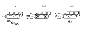
図2および図5(a)に示すように、熱電素子30を互いに接合している積層電極32は、素子接合電極32a、絶縁部材32b、導電性の基板接合部材32cの3層がロウ材によりロウ付けされて接合された構造を有する。また、基板接合部材32cは、低温側熱交換器21(または高温側熱交換器22)が接続された基板40(または基板41)に対してロウ付けされている。なお、符号33は、複数の熱電モジュールを接続して集電するブリッジ電極である。
As shown in FIG. 2 and FIG. 5A, the
本発明では、熱電モジュールの積層電極32に絶縁部材32bを採用して絶縁構造を持たせることで、熱電モジュールの基板40(41)を金属のような弾性基板とすることができ、熱電モジュールの加熱・冷却に伴う上下基板間に発生する熱膨張差に伴う応力を軽減することが可能となる。
In the present invention, the insulating
基板を金属に置換することで、容易に接合が可能となり、フィン等の熱交換を促進するためのコンポーネントを直接基板に接合でき、熱交換器と熱電モジュールを一体化することで、熱を効率的に活用でき、熱電ユニットとしての性能向上が図れると共に従来のボルト締結の挟み込みユニットに比べ、構造を簡略化できる。 By substituting the board with metal, it is possible to join easily, components for promoting heat exchange such as fins can be directly joined to the board, and heat exchanger and thermoelectric module are integrated to efficiently heat It is possible to improve the performance as a thermoelectric unit, and the structure can be simplified as compared with a conventional clamping unit with bolt fastening.
また、本発明では、積層電極32は、セラミック等の絶縁部材32bを、導電性材料(32a、c)で挟み込んで接合することを特徴とし、熱電モジュールの稼動時に加熱が行われると、図5(b)の矢印でその大きさを模式的に示すように、積層電極の3層それぞれに熱膨張が発生する。ここで、本願発明では、素子接合電極32aと基板接合部材32cの線膨張率が等しいため、素子接合電極32aと絶縁部材32b間、および、絶縁部材32bと基板接合部材32c間にそれぞれ曲げ応力が発生しても、これらが等しいために相殺して、絶縁部材32bに反りが発生するのを抑制することができる。これにより、耐熱性、耐久性を高めることができる。また、絶縁部材32bの反りが抑制されることにより、絶縁部材32bの板厚を薄く成立させることが可能となり、これにより熱効率をより向上させることができる。
Further, in the present invention, the
以上のような特徴を有する本発明の熱電モジュールにおいては、温度変化の大きい使われ方においても、破損することのない、かつ高温まで使用できる絶縁機能つき電極が成立する。絶縁機能を電極に付与することで、モジュール基板をより弾性の高い素材に置換でき、モジュールの耐久強度が向上し、より大型化が可能になる。 In the thermoelectric module of the present invention having the above-described features, an electrode with an insulating function that does not break and can be used up to a high temperature is established even when the temperature change is large. By providing an insulating function to the electrodes, the module substrate can be replaced with a material having higher elasticity, the durability of the module is improved, and the size can be increased.
図3は、図2における熱電素子30、低温側基板40、高温側基板41、低温側熱交換器21を分解した斜視図である(高温側熱交換器22は図示略)。また、図4は、(a)は低温側基板40、(b)は高温側基板41のみを示した平面図である。なお、図3においては、積層電極32は簡略化して厚さを省略して示しており、図4においては熱電素子30が配置される位置を破線で示している。図2〜4に示すように、基板40(41)には、熱電素子30(および積層電極32)の接合領域を取り囲むように、溝状のビード43が形成されている。このビード43は、図2に示すように積層電極32が接合されていない領域に形成されているので、両面が固定されておらずフリーな状態にある。そのため、加熱・冷却に伴って伸縮することができ、加熱・冷却に伴う上下基板間に発生する熱膨張差に伴う応力をより軽減することが可能となる。
3 is an exploded perspective view of the
また、図3および4に示すように、基板40(41)には複数のビード43を取り囲むようにさらに深い溝からなるビード42が形成されている。このビード42はビード43よりも変形吸収能が高いため、さらに温度差が大きい加熱・冷却に伴う上下基板間に発生する熱膨張差に伴う応力を、軽減することが可能となる。
As shown in FIGS. 3 and 4, the substrate 40 (41) has a
図5(c)は、本発明の積層電極32の変更例を示しており、絶縁部材32bが2つに分割されて、空隙32dを有している。この態様によれば、ロウ付けがなされた後、素子接合電極32a、絶縁部材32bおよび基板接合部材32cが冷めて収縮する際に、分割された絶縁部材32b間の空隙が、素子接合電極32a、基板接合部材の収縮分を吸収することにより、絶縁部材32b、絶縁部材32bの接合部への曲げ応力、圧縮応力をより一層低減化する。また、分割数は図示した2分割に限定されず、任意の数や向きに分割することができる。
FIG. 5C shows a modified example of the
本発明の熱電モジュールの形成には、接着剤による接着やロウ付け等公知の接合方法を採用することができるが、金属部材の接合過程を含むため、ロウ付けを採用することが好ましい。具体的には、まず素子接合電極32a、絶縁部材32bおよび基板接合部材32cを積層して積層電極32を形成し、次に熱交換器21(22)が一体成型あるいは接合された基板40(41)に対して、積層電極32の基板接合部材側32cを接合し、最後に、積層電極32の素子接合電極側32aを熱電素子30に対して接合することが好ましいが、この順番に限定されない。
For the formation of the thermoelectric module of the present invention, a known joining method such as bonding with an adhesive or brazing can be employed, but brazing is preferably employed because it includes a joining process of metal members. Specifically, first, the
なお、積層電極32を基板40(41)にロウ付けする場合は、基板と積層電極の間に応力が発生するが、基板と積層電極の接合部分は同じ金属同士であり、互いに弾性体であるので、自身で応力を緩和することが可能である。金属箔のような薄い板では、この限りではないが、本願発明で採用しているように0.5mm程度の板であれば、発生する応力は十分に許容できる範囲に収まる。
In addition, when brazing the
本発明では、素子接合電極32aおよび基板接合部材32cによる絶縁部材32bに対する曲げ応力を相殺することを特徴としているが、そのような物性となるようにこれらの部材を選択するには、具体的には、以下の数式を満たすように選択すれば、電極、基板接合部材による絶縁部材に対する曲げ応力が確実に均衡する。
The present invention is characterized in that the bending stress applied to the insulating
L(α1−α2)(TH−TC)E1t1b≒L(α3−α2)(TH−TC)E3t3b
すなわち、両辺を整理して、
(α1−α2)E1t1≒(α3−α2)E3t3
L (α 1 -α 2) ( T H -T C) E 1 t 1 b ≒ L (α 3 -α 2) (T H -T C) E 3 t 3 b
That is, arrange both sides,
(Α 1 −α 2 ) E 1 t 1 ≈ (α 3 −α 2 ) E 3 t 3
但し、各変数は下記の通りである。
E1:素子接合電極のヤング率、E2:絶縁部材のヤング率、E3:基板接合部材のヤング率、α1:素子接合電極の線膨張率、α2:絶縁部材の線膨張率、α3:基板接合部材の線膨張率、t1:素子接合電極の板厚、t3:基板接合部材の板厚、TH:使用温度上限、TC:使用温度下限、L:部材長さ、b:部材幅。
However, each variable is as follows.
E 1 : Young's modulus of the element bonding electrode, E 2 : Young's modulus of the insulating member, E 3 : Young's modulus of the substrate bonding member, α 1 : Linear expansion coefficient of the element bonding electrode, α 2 : Linear expansion coefficient of the insulating member, alpha 3: coefficient of linear expansion of the substrate joining member, t 1: thickness of the element bonding electrodes, t 3: thickness of the substrate bonding member, T H: operating temperature limit, T C: service temperature limit, L: member length , B: member width.
本発明においては、熱源、冷却源または(熱源、冷却源との)熱交換器21(22)は別体の基板40(41)と接合していても、基板と一体に形成されていてもよいが、一体に形成されているとなおよい。基板と、熱源、冷却源または(熱源、冷却源との)熱交換器との接合面による、熱伝達ロスを抑制する。その結果、熱電モジュールとしての発電効率が向上するからである。 In the present invention, the heat source, the cooling source, or the heat exchanger 21 (22) (with the heat source and the cooling source) may be joined to the separate substrate 40 (41) or may be formed integrally with the substrate. Although it is good, it is still better if it is formed integrally. The heat transfer loss due to the joint surface between the substrate and the heat source, the cooling source, or the heat exchanger (with the heat source and the cooling source) is suppressed. As a result, the power generation efficiency as the thermoelectric module is improved.
ロウ材の融点は熱源の温度よりも高い温度であると使用時に接合部分の劣化がなく、好ましい。そのようなロウ材の具体例としては、素子接合電極32a〜熱電素子30間および基板接合部材32c〜基板40(41)間は銀ロウ(BAG−8、融点780℃)が、絶縁部材32b〜素子接合電極32aまたは基板接合部材32c間は銀系チタン入り活性金属ロウ材(CUSIL−ABA、融点780℃)が好ましく使用される。
The melting point of the brazing material is preferably higher than the temperature of the heat source, since there is no deterioration of the joint portion during use. Specific examples of such a brazing material include silver brazing (BAG-8, melting point 780 ° C.) between the
素子接合電極32aについては、熱電素子30と接合される部分に凹部または位置合わせ用のラインを設けても良い。このようにすることで熱電素子30と素子接合電極32aとを接合する際に位置ずれが防止されて、寸法精度を高める事ができる。
About the
基板40(41)は熱源から熱伝導すると膨張し、熱源の運転が停止すると収縮する。ビード42に対応する部分に、複数の積層電極32をつなぐブリッジ電極33を設けることが好ましく、ブリッジ電極33としては、クランク状または蛇腹状とすることで、特に膨張・収縮の大きい部分での電極の破損を防止する。
The substrate 40 (41) expands when conducting heat from the heat source and contracts when the operation of the heat source stops. It is preferable to provide a
本発明の基板40(41)としては耐腐食性、耐熱性、コストの観点から選択され、具体的には鉄、SUS、インコネル、銅等を使用することができ、特に上記観点からSUSおよびインコネルが好ましい。 The substrate 40 (41) of the present invention is selected from the viewpoints of corrosion resistance, heat resistance, and cost. Specifically, iron, SUS, inconel, copper, or the like can be used. In particular, from the above viewpoint, SUS and inconel. Is preferred.
絶縁部材32bとしては十分な絶縁性を有し、熱抵抗が少ないものが選択され、アルミナは安価であるため、また、窒化アルミは熱抵抗が低いため、好ましい。
As the insulating
素子接合電極32aおよび基板接合部材32cとしては電気抵抗および熱抵抗が少ないものが選択され、具体的には銅、アルミ、鉄等を使用することができ、特に銅が好ましい。
As the
また、熱電素子としてはビスマステルル、ハーフホイスラー、ホイスラー、フィルドスクッテルダイトクラスレート等、公知の材料を使用することができる。 As the thermoelectric element, known materials such as bismuth tellurium, half-Heusler, Heusler, filled skutterudite clathrate can be used.
本発明においては、排気ガスと冷却水の流れ方向は特に限定されず、高温側および低温側熱交換器内においてそれぞれが対向する流れあるいは同一方向の流れでもよく、また、直交方向に交わっても良い。すなわち、波状のフィンの形成方向は限定されない。これらの流れ方向は、効果上、大きな差異はないことが分かっている。 In the present invention, the flow directions of the exhaust gas and the cooling water are not particularly limited, and may be flows in the high-temperature side and the low-temperature side heat exchanger that face each other or flow in the same direction, or may intersect in an orthogonal direction. good. That is, the formation direction of the wavy fin is not limited. It has been found that these flow directions are not significantly different in effect.
ケーシング10から外部に取り出す必要のある電極31および冷却水配管20の配置は限定されないが、例えば図1において対向する側面(排気管路11の向こう側)に配置されているもう一つの冷却水配管20を同一側面に変更し、これらが同一側面に並設されていると、組み付け性が容易となり、好ましい。
The arrangement of the
本発明においては、ケーシング10内部に断熱材を充填することが好ましい。断熱材を使用することによって、ケーシング外への放熱をさらに抑制することができ、排気管路内の高温の排気ガスの熱を効率良く熱電素子へ伝導でき、より発電効率を向上させることができる。
In the present invention, the
断熱材は例えば、グラスウール、アルミナ/シリカ系ウール及びペレット・チップ・粉末があげられる。 また断熱材を利用せずとも、ケーシング10内部を真空にすることによって、ケーシング10内部の断熱性を向上させることができる。ケーシング10内部を真空にするためには、例えばケーシング10にワンウェイバルブ(図示せず)を設置し、ケーシング10内部の空気を吸い出すことによって、実施することもできる。
Examples of the heat insulating material include glass wool, alumina / silica wool, and pellets, chips and powder. Moreover, even if it does not utilize a heat insulating material, the heat insulation of the inside of the
本発明においては、排気管路11を複数並列に設け、それぞれに熱電モジュールを装着することもできる。その場合は、複数の排気管路11を高温側熱交換器としてそれぞれに熱電素子を設けるが、熱電素子上に設ける低温側熱交換器は、単一の冷却水配管が複数の熱電素子ユニット間を巡るような態様とすることが好ましい。このような態様であれば、熱電発電装置を複数設けるにも関わらず、構造を簡素化することができるとともに、冷却水の一方向流の単純な流れによって、冷却水配管を複数分岐させて設けた場合と比較して、流動抵抗が増大することを抑制することができる。
In the present invention, a plurality of
積層電極(絶縁部材)および基板の変形を抑制することによって、熱電発電装置の耐久性を向上させ、長寿命化を達成することができる。また、熱電発電装置の発電効率を向上させることができる。 By suppressing the deformation of the laminated electrode (insulating member) and the substrate, it is possible to improve the durability of the thermoelectric generator and achieve a long life. Moreover, the power generation efficiency of the thermoelectric power generator can be improved.
G…熱電発電装置、10…ケーシング、11…排気管路、20…冷却水配管、21…低温側熱交換器、22…高温側熱交換器、30…熱電素子、31…電極、32…積層電極、32a…素子接合電極、32b…絶縁部材、32c…基板接合部材、32d…空隙、33…ブリッジ電極、40…低温側基板、41…高温側基板、42…ビード(大)、43…ビード(小)。
G ... thermoelectric generator, 10 ... casing, 11 ... exhaust pipe, 20 ... cooling water piping, 21 ... low temperature side heat exchanger, 22 ... high temperature side heat exchanger, 30 ... thermoelectric element, 31 ... electrode, 32 ... lamination Electrode, 32a ... element bonding electrode, 32b ... insulating member, 32c ... substrate bonding member, 32d ... gap, 33 ... bridge electrode, 40 ... low temperature side substrate, 41 ... high temperature side substrate, 42 ... bead (large), 43 ... bead (small).
Claims (4)
低温側熱交換器と、
前記高温側熱交換器と前記低温側熱交換器とに挟まれて温度差により発電を行う複数の熱電素子とからなる熱電素子モジュールであって、
前記熱電素子は、ロウ材を介して積層電極と接合され、
前記積層電極は、ロウ材を介して基板と接合され、
前記基板は、前記熱交換器と一体化または接続され、
前記積層電極は、熱電素子側から基板側に向かって順に、導電性の素子接合電極と、絶縁部材と、導電性の基板接合部材とがロウ材を介して接合されてなり、
前記素子接合電極と前記基板接合部材の線膨張差による前記絶縁部材への曲げ応力が等しいことを特徴とする熱電素子モジュール。 A high temperature side heat exchanger;
A low temperature side heat exchanger,
A thermoelectric module comprising a plurality of thermoelectric elements that generate electricity by temperature difference between the high temperature side heat exchanger and the low temperature side heat exchanger,
The thermoelectric element is bonded to the laminated electrode via a brazing material,
The laminated electrode is bonded to the substrate via a brazing material,
The substrate is integrated or connected to the heat exchanger;
The laminated electrode is formed by joining a conductive element bonding electrode, an insulating member, and a conductive substrate bonding member through a brazing material in order from the thermoelectric element side to the substrate side.
The thermoelectric element module, wherein bending stress to the insulating member due to a difference in linear expansion between the element bonding electrode and the substrate bonding member is equal.
The thermoelectric element module according to claim 1, wherein the insulating member in the laminated electrode is divided into a plurality of gaps.
Priority Applications (1)
| Application Number | Priority Date | Filing Date | Title |
|---|---|---|---|
| JP2009092064A JP2010245265A (en) | 2009-04-06 | 2009-04-06 | Thermoelectric module |
Applications Claiming Priority (1)
| Application Number | Priority Date | Filing Date | Title |
|---|---|---|---|
| JP2009092064A JP2010245265A (en) | 2009-04-06 | 2009-04-06 | Thermoelectric module |
Publications (1)
| Publication Number | Publication Date |
|---|---|
| JP2010245265A true JP2010245265A (en) | 2010-10-28 |
Family
ID=43097965
Family Applications (1)
| Application Number | Title | Priority Date | Filing Date |
|---|---|---|---|
| JP2009092064A Pending JP2010245265A (en) | 2009-04-06 | 2009-04-06 | Thermoelectric module |
Country Status (1)
| Country | Link |
|---|---|
| JP (1) | JP2010245265A (en) |
Cited By (12)
| Publication number | Priority date | Publication date | Assignee | Title |
|---|---|---|---|---|
| US8661801B2 (en) | 2011-12-15 | 2014-03-04 | Hyundai Motor Company | Thermoelectric generator of vehicle |
| JP2014086649A (en) * | 2012-10-26 | 2014-05-12 | Hitachi Chemical Co Ltd | Thermoelectric conversion module |
| US9145812B2 (en) | 2011-12-12 | 2015-09-29 | Hyundai Motor Company | Thermoelectric generator of vehicle |
| US9145811B2 (en) | 2011-12-15 | 2015-09-29 | Hyundai Motor Company | Thermoelectric generator of vehicle |
| WO2016013366A1 (en) * | 2014-07-25 | 2016-01-28 | 日立化成株式会社 | Thermoelectric conversion module and method for making same |
| JP2017130596A (en) * | 2016-01-22 | 2017-07-27 | 日立化成株式会社 | Thermoelectric conversion module and manufacturing method thereof |
| KR20180134070A (en) * | 2017-06-08 | 2018-12-18 | 엘지이노텍 주식회사 | Heat conversion device |
| KR20190038101A (en) * | 2017-09-29 | 2019-04-08 | 엘지이노텍 주식회사 | Heat conversion device |
| CN109713116A (en) * | 2017-10-26 | 2019-05-03 | 现代自动车株式会社 | Thermoelectric element unit and its manufacturing method and electrothermal module including it |
| JP2020057633A (en) * | 2018-09-28 | 2020-04-09 | 日立金属株式会社 | Thermoelectric conversion module |
| US11205746B2 (en) | 2017-06-08 | 2021-12-21 | Lg Innotek Co., Ltd. | Heat conversion apparatus |
| KR20250069021A (en) * | 2023-11-10 | 2025-05-19 | 주식회사 리빙케어 | Thermal Power Generation System Using Simulated Waste Heat |
-
2009
- 2009-04-06 JP JP2009092064A patent/JP2010245265A/en active Pending
Cited By (20)
| Publication number | Priority date | Publication date | Assignee | Title |
|---|---|---|---|---|
| US9145812B2 (en) | 2011-12-12 | 2015-09-29 | Hyundai Motor Company | Thermoelectric generator of vehicle |
| US8661801B2 (en) | 2011-12-15 | 2014-03-04 | Hyundai Motor Company | Thermoelectric generator of vehicle |
| US9145811B2 (en) | 2011-12-15 | 2015-09-29 | Hyundai Motor Company | Thermoelectric generator of vehicle |
| JP2014086649A (en) * | 2012-10-26 | 2014-05-12 | Hitachi Chemical Co Ltd | Thermoelectric conversion module |
| WO2016013366A1 (en) * | 2014-07-25 | 2016-01-28 | 日立化成株式会社 | Thermoelectric conversion module and method for making same |
| JP2017130596A (en) * | 2016-01-22 | 2017-07-27 | 日立化成株式会社 | Thermoelectric conversion module and manufacturing method thereof |
| KR102332126B1 (en) * | 2017-06-08 | 2021-11-29 | 엘지이노텍 주식회사 | Heat conversion device |
| US11205746B2 (en) | 2017-06-08 | 2021-12-21 | Lg Innotek Co., Ltd. | Heat conversion apparatus |
| US11903312B2 (en) | 2017-06-08 | 2024-02-13 | Lg Innotek Co., Ltd. | Heat conversion apparatus |
| KR102434261B1 (en) * | 2017-06-08 | 2022-08-19 | 엘지이노텍 주식회사 | Heat conversion device |
| KR20180134070A (en) * | 2017-06-08 | 2018-12-18 | 엘지이노텍 주식회사 | Heat conversion device |
| KR20210145703A (en) * | 2017-06-08 | 2021-12-02 | 엘지이노텍 주식회사 | Heat conversion device |
| KR102334189B1 (en) | 2017-09-29 | 2021-12-02 | 엘지이노텍 주식회사 | Heat conversion device |
| KR20190038101A (en) * | 2017-09-29 | 2019-04-08 | 엘지이노텍 주식회사 | Heat conversion device |
| CN109713116B (en) * | 2017-10-26 | 2023-08-08 | 现代自动车株式会社 | Thermoelectric element unit, method of manufacturing the same, and thermoelectric module including the same |
| CN109713116A (en) * | 2017-10-26 | 2019-05-03 | 现代自动车株式会社 | Thermoelectric element unit and its manufacturing method and electrothermal module including it |
| JP2020057633A (en) * | 2018-09-28 | 2020-04-09 | 日立金属株式会社 | Thermoelectric conversion module |
| JP7215049B2 (en) | 2018-09-28 | 2023-01-31 | 日立金属株式会社 | Thermoelectric conversion module |
| KR20250069021A (en) * | 2023-11-10 | 2025-05-19 | 주식회사 리빙케어 | Thermal Power Generation System Using Simulated Waste Heat |
| KR102905232B1 (en) * | 2023-11-10 | 2025-12-31 | 주식회사 리빙케어 | Thermal Power Generation System Using Simulated Waste Heat |
Similar Documents
| Publication | Publication Date | Title |
|---|---|---|
| JP2010245265A (en) | Thermoelectric module | |
| JP6081583B2 (en) | Thermoelectric module, heat exchanger, exhaust system and internal combustion engine | |
| JP5785763B2 (en) | Heat transfer apparatus and manufacturing method | |
| JP5065077B2 (en) | Thermoelectric generator | |
| JP5443947B2 (en) | Thermoelectric generator | |
| CN102369611A (en) | Thermoelectric generator unit | |
| JP5249662B2 (en) | Thermoelectric conversion module and manufacturing method thereof | |
| US20130327369A1 (en) | Thermoelectric system with mechanically compliant element | |
| JP2011165976A (en) | Thermoelectric converter and thermoelectric conversion method | |
| KR20200125672A (en) | Thermoelectric module for power generation and its manufacturing method | |
| JP2007221895A (en) | Thermoelectric generator | |
| JP7588507B2 (en) | Thermoelectric power generation device | |
| JP5954103B2 (en) | Thermoelectric generator | |
| JP4481606B2 (en) | Thermoelectric converter | |
| JP4622577B2 (en) | Cascade module for thermoelectric conversion | |
| JPH08335722A (en) | Thermoelectric conversion module | |
| JP2010106755A (en) | Thermoelectric power generation device for automobile | |
| JP4082090B2 (en) | Waste heat power generator | |
| JP2012119450A (en) | Thermoelectric conversion module | |
| JP2008066459A (en) | Thermoelectric element module and thermoelectric conversion device using the same | |
| US11316091B2 (en) | Thermoelectric module, frame for the same, and vehicle including the thermoelectric module | |
| JP2008072775A (en) | Waste heat energy recovery device | |
| US20090301538A1 (en) | Thermoelectric module | |
| JP6428749B2 (en) | Thermoelectric generator | |
| JP2011082272A (en) | Thermoelectric cooling device |