JP2010218651A - Magnetic recording and reproducing device and magnetic tape cartridge - Google Patents
Magnetic recording and reproducing device and magnetic tape cartridge Download PDFInfo
- Publication number
- JP2010218651A JP2010218651A JP2009066488A JP2009066488A JP2010218651A JP 2010218651 A JP2010218651 A JP 2010218651A JP 2009066488 A JP2009066488 A JP 2009066488A JP 2009066488 A JP2009066488 A JP 2009066488A JP 2010218651 A JP2010218651 A JP 2010218651A
- Authority
- JP
- Japan
- Prior art keywords
- magnetic tape
- magnetic
- region
- tape cartridge
- recording
- Prior art date
- Legal status (The legal status is an assumption and is not a legal conclusion. Google has not performed a legal analysis and makes no representation as to the accuracy of the status listed.)
- Withdrawn
Links
Images


Landscapes
- Magnetic Record Carriers (AREA)
Abstract
【課題】本発明は、低湿度がもたらすエラーレートの悪化が抑制された磁気記録再生装置を提供する。
【解決手段】筐体110と、磁気テープカートリッジを収納しうる磁気テープカートリッジ収容部90と、磁気テープを移送させうる移送機構と、磁気テープ50への情報の記録および再生を行いうる磁気ヘッド30と、所定量の水分を含んだ熱可塑性吸水性樹脂を含む、1つ以上の調湿部材40とを含み、筐体内において、磁気テープカートリッジ収容部、移送機構、および磁気ヘッドが配置された領域Aと、残余の領域Bとが、隔離部材により隔たれており、調湿部材は、領域A内に配置され、熱可塑性吸水性樹脂は、その限界吸水量が10g/g以上であり、熱可塑性吸水性樹脂の総乾燥重量が、領域A内の空間100cm3あたり1.0g〜10.0gである、磁気記録再生装置。
【選択図】図1The present invention provides a magnetic recording / reproducing apparatus in which deterioration of an error rate caused by low humidity is suppressed.
A housing 110, a magnetic tape cartridge accommodating portion 90 capable of accommodating a magnetic tape cartridge, a transport mechanism capable of transporting the magnetic tape, and a magnetic head 30 capable of recording and reproducing information on the magnetic tape 50. And one or more humidity control members 40 including a thermoplastic water-absorbing resin containing a predetermined amount of moisture, and a region in which the magnetic tape cartridge housing portion, the transfer mechanism, and the magnetic head are arranged in the housing A and the remaining region B are separated by a separating member, the humidity control member is disposed in the region A, and the thermoplastic water absorbent resin has a limit water absorption of 10 g / g or more, and is thermoplastic. A magnetic recording / reproducing apparatus in which the total dry weight of the water-absorbent resin is 1.0 g to 10.0 g per 100 cm 3 of space in the region A.
[Selection] Figure 1
Description
本発明は、磁気記録再生装置、および磁気テープカートリッジに関する。 The present invention relates to a magnetic recording / reproducing apparatus and a magnetic tape cartridge.
コンピューターに搭載されたハードディスクに記録されているデータをバックアップするものとして、磁気テープが多く用いられている。データバックアップ用の磁気テープの分野では、ハードディスクの大容量化に伴い、1巻あたり数百GB〜数TBの記憶容量を有する磁気テープが商品化されている。今後、さらなるハードディスクの大容量化に対応するため、データバックアップ用の磁気テープの高容量化は不可欠である。 Magnetic tape is often used to back up data recorded on hard disks installed in computers. In the field of magnetic tapes for data backup, magnetic tapes having a storage capacity of several hundred GB to several TB per volume are commercialized as the capacity of hard disks increases. In the future, it will be indispensable to increase the capacity of magnetic tape for data backup in order to cope with further increase in capacity of hard disks.
この高容量化を達成するためには、磁気テープの線記録密度を上げることが必須であり、そのために、磁気テープの磁性層表面は極めて平滑に仕上げられている。よって、磁性層の磁気ヘッドに対する研磨能(クリーニング性能)は低下する傾向にある。 In order to achieve this high capacity, it is essential to increase the linear recording density of the magnetic tape. For this reason, the surface of the magnetic layer of the magnetic tape is extremely smooth. Therefore, the polishing ability (cleaning performance) of the magnetic layer with respect to the magnetic head tends to decrease.
このような磁気テープに対して情報の記録および再生を可能とする磁気記録再生装置では、短波長の微小な磁束を検出するために、MRヘッドが用いられている。高密度記録された磁気テープでは、磁束が微小で短波長である。そのため、再生時に磁気ヘッドの表面に僅かな汚れが付着すること等が原因で、磁気ヘッドの表面と磁気テープの磁性層表面との間に僅かなスペーシングが発生すると、スペーシング損失による書き込み損じと、バイアス磁界の変化により再生出力が低下し、再生エラーが生じてエラーレートが増大するなどの問題が発生する。このような現象は、特に低湿環境下で顕著に発生し、大きな問題となっている。 In a magnetic recording / reproducing apparatus capable of recording and reproducing information on such a magnetic tape, an MR head is used to detect a minute magnetic flux having a short wavelength. A magnetic tape recorded with high density has a small magnetic flux and a short wavelength. For this reason, if slight spacing occurs between the surface of the magnetic head and the magnetic layer of the magnetic tape due to slight contamination on the surface of the magnetic head during reproduction, etc., write loss due to spacing loss will occur. As a result, the reproduction output decreases due to the change of the bias magnetic field, causing a problem such as a reproduction error and an increase in the error rate. Such a phenomenon occurs remarkably in a low-humidity environment and is a serious problem.
このような背景下、珪藻土等の調湿材料を含んだ調湿部材を含む磁気テープカートリッジが提案されている(特許文献1参照)。 Under such a background, a magnetic tape cartridge including a humidity control member including a humidity control material such as diatomaceous earth has been proposed (see Patent Document 1).
しかし、上記特許文献1に開示されている技術は、磁気テープカートリッジ内を所定の湿度範囲内に調整可能とするものであるため、磁気テープカートリッジ内での磁気テープの品質保持や幅方向の寸法の保持には寄与するものの、上記磁気ヘッドの表面に付着する僅かな汚れ等が引き起こす、エラーレートの増大の問題の解決には、十分に寄与しない。 However, since the technique disclosed in Patent Document 1 makes it possible to adjust the inside of the magnetic tape cartridge within a predetermined humidity range, it is possible to maintain the quality of the magnetic tape in the magnetic tape cartridge and to measure the width in the width direction. However, it does not sufficiently contribute to solving the problem of an increase in error rate caused by slight dirt adhering to the surface of the magnetic head.
本発明は、低湿度がもたらすエラーレートの増大が抑制された磁気記録再生装置を提供する。 The present invention provides a magnetic recording / reproducing apparatus in which an increase in error rate caused by low humidity is suppressed.
本発明の磁気記録再生装置は、
磁気テープカートリッジの磁気テープに情報を記録および再生可能とする磁気記録再生装置であって、
筐体と、
前記磁気テープカートリッジを収納しうる磁気テープカートリッジ収容部と、
前記磁気テープを移送させうる移送機構と、
前記磁気テープへの情報の記録および再生を行いうる磁気ヘッドと、
所定量の水分を含んだ熱可塑性吸水性樹脂を含む、1つ以上の調湿部材とを含み、
前記筐体内において、前記磁気テープカートリッジ収容部、前記移送機構、および前記磁気ヘッドが配置された領域Aと、残余の領域Bとが、隔離部材により隔たれており、
前記調湿部材は、前記領域A内に配置され、前記熱可塑性吸水性樹脂は、その限界吸水量が10g/g以上であり、前記熱可塑性吸水性樹脂の総乾燥重量が、前記領域A内の空間100cm3あたり1.0g〜10.0gであることを特徴とする。
The magnetic recording / reproducing apparatus of the present invention
A magnetic recording / reproducing apparatus capable of recording and reproducing information on a magnetic tape of a magnetic tape cartridge,
A housing,
A magnetic tape cartridge housing portion capable of housing the magnetic tape cartridge;
A transfer mechanism capable of transferring the magnetic tape;
A magnetic head capable of recording and reproducing information on the magnetic tape;
Including one or more humidity control members including a thermoplastic water absorbent resin containing a predetermined amount of moisture,
In the housing, the region A where the magnetic tape cartridge housing portion, the transfer mechanism, and the magnetic head are disposed, and the remaining region B are separated by a separating member,
The humidity control member is disposed in the region A, the thermoplastic water absorbent resin has a limit water absorption of 10 g / g or more, and the total dry weight of the thermoplastic water absorbent resin is in the region A. It is characterized by being 1.0 g to 10.0 g per 100 cm 3 of the space.
本発明の磁気記録再生装置は、
本発明の磁気記録再生装置により情報が記録および再生される磁気テープを含む磁気テープカートリッジであって、
ケースと、
前記ケース内に配置された磁気テープと、
前記磁気テープが巻回されたハブ部を含むリールと、
所定量の水分を含んだ熱可塑性吸水性樹脂を含む1つ以上の調湿部材と、を含むことを特徴とする。
The magnetic recording / reproducing apparatus of the present invention
A magnetic tape cartridge including a magnetic tape on which information is recorded and reproduced by the magnetic recording / reproducing apparatus of the present invention,
Case and
A magnetic tape disposed in the case;
A reel including a hub portion around which the magnetic tape is wound;
One or more humidity control members containing a thermoplastic water-absorbing resin containing a predetermined amount of moisture.
本発明によれば、低湿度がもたらすエラーレートの増大が抑制された磁気記録再生装置、および、この磁気記録再生装置を用いて好適に情報が記録および再生される磁気テープカートリッジを提供できる。 According to the present invention, it is possible to provide a magnetic recording / reproducing apparatus in which an increase in error rate caused by low humidity is suppressed, and a magnetic tape cartridge on which information is suitably recorded and reproduced using this magnetic recording / reproducing apparatus.
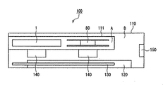
図1は、本発明の磁気記録再生装置の一例の内部構成を示す平面概略図であり、図2は、図1に示した磁気記録再生装置のI-I'断面概略図である。図3は、本発明の磁気記録再生装置の他の一例を説明する部分概略図である。尚、図の理解の容易化のために、図2において、図1中の、磁気ヘッド20、アクチュエータ30、調湿部材40、磁気テープ50、テープガイド60は省略している。
FIG. 1 is a schematic plan view showing the internal configuration of an example of the magnetic recording / reproducing apparatus of the present invention. FIG. 2 is a schematic cross-sectional view taken along the line II ′ of the magnetic recording / reproducing apparatus shown in FIG. FIG. 3 is a partial schematic diagram illustrating another example of the magnetic recording / reproducing apparatus of the present invention. In FIG. 2, the
本実施の形態の磁気記録再生装置100は、磁気ヘッド20と、アクチュエータ30と、テープガイド60と、巻き取りリール80と、磁気テープカートリッジを収納可能とするカートリッジ収納部90と、調湿部材40と、回路基板130と、駆動部140と、ファン150と、電源部120と、これらを収容する筐体110とを含む。筐体110は、取り出し口110a(図1および図2参照)を開閉可能に覆う開閉扉(図示せず。)を有している。
The magnetic recording / reproducing
磁気ヘッド20は、磁気テープ50に各種情報を書き込み、および、磁気テープ50に記録された各種情報を読み出すことができる。磁気ヘッド20は、例えば、磁気抵抗効果素子(MR素子)を用いたMRヘッドで構成される。
The
アクチュエータ30は、磁気テープ50に各種情報を記録する際、または磁気テープ50に記録された各種情報を読み出す際に、磁気ヘッド20を磁気テープ5の幅方向に移動させるように機能する。
The
テープガイド60は、磁気テープ50が磁気記録再生装置100内の所定の位置を走行可能なように、磁気テープ5を案内するものである。テープガイド6は、例えば、略円筒形状のローラを備えている。また、テープガイド60は、磁気ヘッド20の入側及び出側にそれぞれ配され、磁気ヘッド20に対する磁気テープ5の相対位置を規制している。
The tape guide 60 guides the magnetic tape 5 so that the
巻き取りリール80は、磁気テープカートリッジから引き出された磁気テープ50が巻き回されるリールである。巻き取りリール80は、別途設けられたモータ等の駆動部140により回転駆動される。
The take-
上記テープガイド60および巻き取りリール80等からなる磁気テープ50を移送させる構成は、本発明における移送機構の一例である。本実施の形態の磁気記録再生装置100は、LTO(Linear Tape-Open)規格に準拠した磁気テープ50への情報の記録および再生が行えるものである。磁気記録再生装置100で磁気テープ50へ情報を書き込む際は、磁気テープ50をその始端から終端まで走行させながらデータトラックに沿って磁気ヘッド20により情報を書き込む。次に、磁気ヘッド20を磁気テープ50の幅方向に所定量移動させ、磁気テープ50をその終端から始端まで走行させながら別のデータトラックに沿って情報を書き込む。上記動作を繰り返して、磁気テープ50の長手方向に平行な複数のデータトラックに沿って情報を書き込む。
The configuration for transferring the
筐体110内の領域Aには、テープガイド60と巻き取りリール80とを含む移送機構、磁気テープカートリッジ収容部90、磁気ヘッド20、アクチュエータ30が配置されている。一方、残余の領域B内には、ファン150、電源部120、駆動部140、回路基板130が配置されている。そして、領域Aと領域Bは、隔離部材111により隔たれている。すなわち、磁気記録再生装置の稼動中に筐体110内の磁気テープ50が存在し得る領域(領域A)と、磁気記録再生装置の稼動中に発熱する構成部品(電源部120、駆動部140、回路基板130等)と、当該発熱により加熱された空気を筐体外に排出して領域B内の温度を制御可能とするファン150とを含む領域(領域B)とが、隔離部材111により隔たれている。ここで、「隔たれている」とは、領域Aと領域Bとの気体の積極的な流通が阻害されている状態を意味する。
In a region A in the
したがって、ファン150により引き起こされる気体の流れや、加熱された空気の拡散等が原因で、領域A内において温度変化および湿度変化が生じることを抑制可能とし、かつ、領域Aの湿度を効率的に所望の範囲内(20〜60%RH)の値にできる限りにおいて、領域Aと領域Bとの間の気体の流通が隔離部材111により完全に妨げられる必要はない。よって、隔離部材111の形状等についても特に制限はなく、例えば、板状、磁気テープカートリッジ1を出し入れ可能とする開口部を有するボックス状等であってもよい。
Therefore, it is possible to suppress the occurrence of temperature change and humidity change in the region A due to the gas flow caused by the
しかし、隔離部材111の形状は、可能なかぎり、領域Aが、領域A外(例えば、領域Bおよび磁気記録再生装置外)の温度および湿度の影響を受けることを抑制可能な形状であると好ましい。具体的には、隔離部材111は、領域A内の気体と領域A外の気体の行き来を許す開口として磁気記録再生装置を機能させる上で必要な開口のみを有したボックス状のものであると好ましい。上記開口としては、例えば、ドライブ信号等の信号の伝達用配線等を領域Aおよび領域Bにまたがって配置させるために要する開口(図示せず)、駆動部140と磁気テープカートリッジ内に配置されたリール7(図6参照)および巻き取りリール80との係合のために要する開口(図示せず)、および磁気テープカートリッジを出し入れ可能とする開口等が挙げられる。
However, it is preferable that the shape of the
上記領域Aは、その湿度をより効率的に所望の範囲(20〜60%RH)の値に均一化でき、かつ、吸収性樹脂の使用量を低減できるという理由から、可能なかぎり小さいと好ましい。 The area A is preferably as small as possible because the humidity can be more efficiently uniformized to a desired range (20 to 60% RH) and the amount of absorbent resin used can be reduced. .
尚、領域Aの湿度が20%RHよりも低いと、エラーレートの増大に伴う記録容量の低下の程度が大きくなる。一方、領域Aの湿度が60%RHよりも高いと、磁気ヘッドのテープ摺動面の摩擦係数が高くなることで、磁気テープの摺動スピードを一定に保つことが困難になる。よって、磁気ヘッドは、磁気テープから正常に情報を読み出すことができず、エラーレートが増大する。 Note that when the humidity in the area A is lower than 20% RH, the degree of decrease in the recording capacity accompanying the increase in the error rate increases. On the other hand, when the humidity in the region A is higher than 60% RH, the friction coefficient of the tape sliding surface of the magnetic head becomes high, and it becomes difficult to keep the sliding speed of the magnetic tape constant. Therefore, the magnetic head cannot normally read information from the magnetic tape, and the error rate increases.
隔離部材111の材料については、領域Aと領域Bとの気体の積極的な流通を阻害可能とするものであれば特に制限はなく、例えば、筐体110と同じ材料であってもよい。
The material of the
調湿部材40は、例えば、所定量の水分を含んだ熱可塑性吸水性樹脂を含む。
The
所定量の水分を含んだ熱可塑性吸水性樹脂は、雰囲気の湿度が、第1の湿度以上になるとその雰囲気の水分を吸収し(「吸湿」とも言う。)、雰囲気の湿度が第1の湿度よりも低い第2の湿度以下になると、水分を雰囲気に放出する(「放湿」とも言う。)性質を有している。そのため、湿度変化に伴い、当該熱可塑性吸水性樹脂により吸湿、放湿が繰り返され、領域A内の湿度は所定範囲(20〜60%RH)内に保持される。よって、磁気ヘッド20の周囲の湿度についても上記所定範囲内に保持されることとなる。これにより、磁気ヘッド20の周囲の湿度が低くなり過ぎることが抑制され、その結果、磁気テープ50による磁気ヘッド20の研磨が良好に行われ、磁気ヘッド20の汚れに起因して生じるエラーレートの悪化が抑制される。また湿度が高くなりすぎることによる摩擦係数の上昇が抑制される。
The thermoplastic water-absorbing resin containing a predetermined amount of moisture absorbs moisture in the atmosphere when the humidity in the atmosphere becomes equal to or higher than the first humidity (also referred to as “moisture absorption”), and the humidity in the atmosphere is the first humidity. When the humidity is lower than the lower second humidity, water is released into the atmosphere (also referred to as “moisture release”). Therefore, with the change in humidity, moisture absorption and moisture release are repeated by the thermoplastic water absorbent resin, and the humidity in the region A is maintained within a predetermined range (20 to 60% RH). Therefore, the humidity around the
磁気記録再生装置が稼動している時の、領域A内の温度は、通常、10℃〜60℃であり、好ましくは、20℃〜50℃である。この温度範囲における、磁気ヘッド20の周囲の湿度は、磁気テープ50による磁気ヘッド20の良好な研磨およびエラーレートの悪化の抑制等を考慮すると、20〜60%RHであることが好ましいが、同様の理由により30〜55%RHであると好ましい。したがって、所定量の水分を含んだ熱可塑性吸水性樹脂による吸湿が起こる第1の湿度は、例えば55%RHより高く、かつ60%RH以下の湿度であると好ましく、当該熱可塑性吸水性樹脂による放湿が起こる第2の湿度は30%RHよりも低くかつ20%RH以上の湿度であるとより好ましい。
The temperature in the region A when the magnetic recording / reproducing apparatus is operating is usually 10 ° C. to 60 ° C., and preferably 20 ° C. to 50 ° C. The humidity around the
なお、磁気記録再生装置の稼動中、領域A内では、巻き取りリール80が回転し、磁気テープ50が走行しているので、巻き取りリール80および磁気テープ50の周囲の気体は、比較的速く流動している。よって、例えば、図1に示されるように、1つ以上の調湿部材40を、領域A内の磁気ヘッド20に比較的近い位置に配置しても、領域A内の磁気ヘッド20から比較的離れた箇所の湿度も、磁気ヘッド20の周囲の湿度に徐々に等しくなり、領域A内の湿度は、ほぼ均一になる。
During operation of the magnetic recording / reproducing apparatus, the take-
したがって、調湿部材40の配置位置は、領域A内であれば特に制限はない。調湿部材40は、例えば、磁気ヘッド20の近くに固定されていてもよいが、領域A内の磁気ヘッド20から離れた場所に配置されてもよい。具体的には、図3に示されるように、調湿部材40は、例えば、アクチュエータ30の底面上および/又は上面上に固定されてもよい。または、図4Aおよび図4Bに示されるように、調湿部材400は、移送機構を構成する巻き取りリール80に固定されていてもよい。また、調湿部材は、固定対象に対して着脱可能であってもよい。
Therefore, the arrangement position of the
巻き取りリール80は、磁気テープが巻かれうる軸部50aと、相互に離間して軸部50aの両端部に固定された、1対の円盤状のフランジ50b,50cとを有するが、調湿部材40は、各フランジ50b,50cの相互に対向する面51b,51c、またはその反対面52b,52cに各々固定されていてもよい。
熱可塑性吸水性樹脂としては、特に制限はなく、従来公知の熱可塑性吸水性樹脂が用いられる。熱可塑性吸水性樹脂としては、例えば、ポリアルキレンオキシドとポリオールとを、イソシアネート化合物と反応させることにより得られるポリアルキレンオキシド変性物が挙げられる。
The take-
There is no restriction | limiting in particular as a thermoplastic water absorbing resin, A conventionally well-known thermoplastic water absorbing resin is used. Examples of the thermoplastic water-absorbing resin include a modified polyalkylene oxide obtained by reacting a polyalkylene oxide and a polyol with an isocyanate compound.
前記ポリアルキレンオキシドとしては、数平均分子量5000〜30000のポリエチレンオキシド、ポリプロピレンオキシド、エチレンオキシド/プロピレンオキシド共重合体、ポリブチレンオキシドおよびこれらの混合物等を挙げることができる。これらの中でも、得られるポリアルキレンオキシド変性物が親水性に優れる観点から、数平均分子量5000〜30000のポリエチレンオキシドおよびエチレンオキシド/プロピレンオキシド共重合体が好適に用いられる。数平均分子量が5000未満の場合、得られるポリアルキレンオキシド変性物の溶融粘度が高くなり、成型の際に成型温度を高温にする必要があり、そのためポリアルキレンオキシド変性物の分解や、得られる成型体が着色するため好ましくない。数平均分子量が30000を超える場合、得られるポリアルキレンオキシド変性物の溶融粘度が低くなり、成型の際にポリアルキレンオキシド変性物がはみ出易いため好ましくない。 Examples of the polyalkylene oxide include polyethylene oxide having a number average molecular weight of 5000 to 30000, polypropylene oxide, ethylene oxide / propylene oxide copolymer, polybutylene oxide, and mixtures thereof. Among these, polyethylene oxide and ethylene oxide / propylene oxide copolymers having a number average molecular weight of 5000 to 30000 are preferably used from the viewpoint that the resulting polyalkylene oxide modified product is excellent in hydrophilicity. When the number average molecular weight is less than 5,000, the resulting polyalkylene oxide-modified product has a high melt viscosity, and it is necessary to increase the molding temperature during molding. Therefore, the polyalkylene oxide-modified product is decomposed and the resulting molding is obtained. This is not preferable because the body is colored. When the number average molecular weight exceeds 30,000, the resulting polyalkylene oxide-modified product has a low melt viscosity, and the polyalkylene oxide-modified product tends to protrude during molding.
前記ポリオールとしては、同一分子内に水酸基(−OH)を2個有する有機化合物、例えば、エチレングリコール、プロピレングリコール、1,3−ブタンジオール、1,4−ブタンジオール、1,5−ペンタンジオール、ヘキシレングリコール、オクチレングリコール、グリセリルモノアセテート、グリセリルモノブチレート、1,6−ヘキサンジオールおよび1,9−ノナンジオール等を挙げることができる。これらの中でも、ポリアルキレンオキシドとの相溶性、反応性の観点から1,4−ブタンジオールが好適に用いられる。 Examples of the polyol include organic compounds having two hydroxyl groups (—OH) in the same molecule, such as ethylene glycol, propylene glycol, 1,3-butanediol, 1,4-butanediol, 1,5-pentanediol, Examples include hexylene glycol, octylene glycol, glyceryl monoacetate, glyceryl monobutyrate, 1,6-hexanediol, and 1,9-nonanediol. Among these, 1,4-butanediol is preferably used from the viewpoint of compatibility with polyalkylene oxide and reactivity.
前記ポリオールの混合量は、前記ポリアルキレンオキシド1モルに対して、0.5〜6倍モル、好ましくは1〜5倍モルであることが望ましい。ポリオールの混合量が0.5倍モル未満の場合、得られるポリアルキレンオキシド変性物の溶融粘度が低くなり、成型の際にポリアルキレンオキシド変性物がはみ出し易いため好ましくない。また、得られるポリアルキレンオキシド変性物の吸水能は高いもののゲル強度が低いため、吸液時の成型体の表面がヌルヌルしたりするため好ましくない。ポリオールの混合量が6倍モルを超える場合、得られるポリアルキレンオキシド変性物の溶融粘度が高くなり、成型の際に成型温度を高温にする必要があり、そのためポリアルキレンオキシド変性物の分解や、得られる成型体が着色するため好ましくない。また、得られるポリアルキレンオキシド変性物の吸水能が低くゲル強度が高いため、吸水時の成型体からゲルが脱離しやすくなるため好ましくない。なお、ポリアルキレンオキシドのモル数は、その重量を数平均分子量で除することにより求めることができる。 The mixing amount of the polyol is 0.5 to 6 times mol, preferably 1 to 5 times mol for 1 mol of the polyalkylene oxide. When the mixing amount of the polyol is less than 0.5 times mol, the melt viscosity of the resulting polyalkylene oxide-modified product becomes low, and the polyalkylene oxide-modified product tends to protrude during molding, which is not preferable. Moreover, although the water absorption ability of the obtained polyalkylene oxide modified product is high, since the gel strength is low, the surface of the molded body at the time of liquid absorption is not preferable. When the mixing amount of the polyol exceeds 6 times mol, the melt viscosity of the resulting polyalkylene oxide modified product becomes high, and it is necessary to raise the molding temperature during molding, so the polyalkylene oxide modified product is decomposed, Since the obtained molding is colored, it is not preferable. Moreover, since the water absorption ability of the polyalkylene oxide modified product obtained is low and the gel strength is high, it is not preferable because the gel is easily detached from the molded product at the time of water absorption. The number of moles of polyalkylene oxide can be determined by dividing the weight by the number average molecular weight.
前記イソシアネート化合物としては、同一分子内にイソシアネート基(−NCO)を2個以上有する有機化合物、例えば、ジシクロヘキシルメタン−4,4’−ジイソシアネ−ト(HMDI)、キシリレンジイソシアネート(XDI)、4,4’−ジフェニルメタンジイソシアネート(MDI)、1,6−ヘキサメチレンジイソシアネート(HDI)、1,6−ジメチルベンゾール−2,4−ジイソシアネートおよび2,4−トリレンジイソシアネート(TDI)等を挙げることができる。これらの中でも、耐候性に優れる観点からジシクロヘキシルメタン−4,4’−ジイソシアネ−トまたは1,6−ヘキサメチレンジイソシアネートが好適に用いられる。 Examples of the isocyanate compound include organic compounds having two or more isocyanate groups (—NCO) in the same molecule, such as dicyclohexylmethane-4,4′-diisocyanate (HMDI), xylylene diisocyanate (XDI), 4, Examples include 4′-diphenylmethane diisocyanate (MDI), 1,6-hexamethylene diisocyanate (HDI), 1,6-dimethylbenzole-2,4-diisocyanate, and 2,4-tolylene diisocyanate (TDI). Among these, dicyclohexylmethane-4,4'-diisocyanate or 1,6-hexamethylene diisocyanate is preferably used from the viewpoint of excellent weather resistance.
前記イソシアネート化合物の使用量は、前記ポリアルキレンオキシドとポリオールの合計モル数に対して、0.8〜1.2倍モル、好ましくは0.9〜1.1倍モルであることが好ましい。イソシアネート化合物の使用量が0.8倍モル未満の場合、得られるポリアルキレンオキシド変性物の溶融粘度が低くなり、成型の際にポリアルキレンオキシド変性物がはみ出易いため好ましくない。また、得られるポリアルキレンオキシド変性物の吸水能は高いもののゲル強度が低いため、吸水時の成型体ト表面がヌルヌルするため好ましくない。また、イソシアネート化合物の使用量が1.2倍モルを超える場合、得られるポリアルキレンオキシド変性物の溶融粘度が高くなり、成型の際に成型温度を高温にする必要があり、そのためポリアルキレンオキシド変性物の分解や、得られる成型体が着色するため好ましくない。また、得られるポリアルキレンオキシド変性物の吸水能が低くゲル強度が高いため、吸液時の成型体からゲルが脱離しやすくなるため好ましくない。 The amount of the isocyanate compound used is preferably 0.8 to 1.2 times mol, and preferably 0.9 to 1.1 times mol, based on the total number of moles of the polyalkylene oxide and polyol. When the amount of the isocyanate compound used is less than 0.8 times mol, the melt viscosity of the resulting polyalkylene oxide-modified product becomes low, and the polyalkylene oxide-modified product tends to protrude during molding, which is not preferable. Moreover, although the water absorption ability of the obtained polyalkylene oxide modified product is high, since the gel strength is low, the molded product surface at the time of water absorption is not preferable. Further, when the amount of the isocyanate compound used exceeds 1.2 moles, the melt viscosity of the resulting polyalkylene oxide-modified product becomes high, and it is necessary to increase the molding temperature during molding. This is not preferable because the product is decomposed and the resulting molded product is colored. Moreover, since the water-absorbing ability of the polyalkylene oxide-modified product obtained is low and the gel strength is high, it is not preferable because the gel is likely to be detached from the molded article during liquid absorption.
前記ポリアルキレンオキシドとポリオールとの混合物をイソシアネート化合物と反応させる方法としては、適当な溶媒、例えば、トルエン、キシレン、ジメチルホルムアミド等を用いた溶液状で反応させることも可能であるが、分散状で反応させる方法や、粉末状または固体状で両者を均一に混合した後、所定の温度に加熱して反応させることもできる。工業的実施の見地からは、各原料を溶融状態で連続的に供給し多軸押出機中で混合、反応させる方法が好ましい。上記反応の温度は、通常70〜210℃であることが望ましい。なお、この反応系にトリエチルアミン、トリエタノールアミン、ジブチルスズジアセテート、ジブチルスズジラウレート、スタナスオクトエート、トリエチレンジアミン等を少量添加することにより、反応を促進させることもできる。 As a method of reacting the mixture of the polyalkylene oxide and the polyol with the isocyanate compound, it is possible to react in a solution using an appropriate solvent such as toluene, xylene, dimethylformamide, etc. It can also be made to react, and after mixing both uniformly by powder form or solid form, it can also be made to react by heating to predetermined temperature. From the viewpoint of industrial implementation, a method in which each raw material is continuously supplied in a molten state and mixed and reacted in a multi-screw extruder is preferable. The temperature of the above reaction is usually desirably 70 to 210 ° C. The reaction can be accelerated by adding a small amount of triethylamine, triethanolamine, dibutyltin diacetate, dibutyltin dilaurate, stannous octoate, triethylenediamine, or the like to the reaction system.
前記製造方法により得られるポリアルキレンオキシド変性物は、通常、ペレット、シート、フィルム等の形態で得られる。得られるポリアルキレンオキシド変性物はこれらペレット、シート、フィルム等の形態のまま使用することもできるが、粉砕機等により粉砕して用いても良い。 The polyalkylene oxide-modified product obtained by the production method is usually obtained in the form of pellets, sheets, films and the like. The resulting polyalkylene oxide-modified product can be used in the form of pellets, sheets, films, etc., but may be used after being pulverized by a pulverizer or the like.
また、ポリアルキレンオキシド変性物の限界吸水量は、10〜100g/gが好ましく、20〜50g/gであるとより好ましい。ポリアルキレンオキシド変性物の限界吸水量が1g/g未満の場合、吸水量が少ないため、調湿性能が十分でないため好ましくない。また、ポリアルキレンオキシド変性物の限界吸水量が100g/gを超えるものは、製造が困難である。ここで、本発明における限界吸水量とは、以下の方法で測定、算出した値をいう。まず、イオン交換水100mlに、ポリアルキレンオキシド変性物1gを添加し、24時間穏やかに撹拌して十分膨潤させる。次に、重量(Wa)gを測定した目開き75μmのJIS標準金属ふるいで膨潤ゲルをろ過する。膨潤ゲルを含んだ金属ふるいを、適度に傾けた状態で30分間放置し、余剰の水分を除く。膨潤ゲルを含んだ金属ふるいの重量(Wb)gを測定し、以下の式から限界吸水量を算出する。
限界吸水量(g/g)=[Wb−Wa](g)/乾燥状態のポリアルキレンオキシド変性物の重量(g)
ここで「乾燥状態」とは、吸水させていない状態の熱可塑性吸水性樹脂について、70℃で6時間減圧(圧力1Pa以下)乾燥させた直後の状態をいう。
Moreover, 10-100 g / g is preferable and, as for the limit water absorption of a polyalkylene oxide modified material, it is more preferable in it being 20-50 g / g. When the limit water absorption amount of the polyalkylene oxide modified product is less than 1 g / g, the water absorption amount is small and the humidity control performance is not sufficient, which is not preferable. In addition, it is difficult to produce a polyalkylene oxide-modified product having a limit water absorption exceeding 100 g / g. Here, the limit water absorption in the present invention refers to a value measured and calculated by the following method. First, 1 g of polyalkylene oxide-modified product is added to 100 ml of ion-exchanged water, and the mixture is gently swirled for 24 hours to be sufficiently swollen. Next, the swollen gel is filtered through a JIS standard metal sieve having a mesh size of 75 μm and measuring the weight (Wa) g. The metal sieve containing the swollen gel is allowed to stand for 30 minutes in a moderately tilted state to remove excess water. The weight (Wb) g of the metal sieve containing the swollen gel is measured, and the limit water absorption is calculated from the following equation.
Limit water absorption (g / g) = [Wb−Wa] (g) / weight of polyalkylene oxide modified product in dry state (g)
Here, the “dried state” refers to a state immediately after drying a thermoplastic water-absorbing resin in a state of not absorbing water at 70 ° C. for 6 hours under reduced pressure (pressure 1 Pa or less).
乾燥状態にある熱可塑性吸水性樹脂は、所定量の水分を含有させた場合に、高い放湿性能が得られ、かつ、取り扱い性も良好であるという理由から、その吸湿性、すなわち、30℃、80%RHの環境下に24hr放置したときの吸水量が、熱可塑性吸水性樹脂1g(乾燥重量)当り0.2g〜5gであると好ましく、0.5〜2gであるとより好ましい。
ここで、乾燥重量とは、積極的に吸水させていない状態の熱可塑性吸水性樹脂の、70℃で6時間減圧(圧力1Pa以下)乾燥させた直後の重量のことである。
The thermoplastic water-absorbent resin in a dry state has a high moisture-releasing performance when it contains a predetermined amount of water, and has good hygroscopicity, ie, 30 ° C. The water absorption when left for 24 hours in an environment of 80% RH is preferably 0.2 to 5 g, more preferably 0.5 to 2 g, per 1 g (dry weight) of the thermoplastic water-absorbing resin.
Here, the dry weight is a weight immediately after drying a reduced pressure (pressure 1 Pa or less) at 70 ° C. for 6 hours in a thermoplastic water-absorbing resin that is not actively absorbing water.
また、上記のようにして、30℃、80%RHの環境下に24hr放置して吸湿(吸水)させた熱可塑性吸水性樹脂を、20℃、10%RHの環境下に24hr放置したときの放湿率は、45〜100%であると好ましい。この場合、低湿環境下でも、領域A内の調湿が良好に行えるので好ましい。
ここで、放湿率とは、下式で定義される値である。
放湿率(%)=(a−b)/(a−c)×100
a:30℃、80%RHの環境下に24hr放置したときの熱可塑性吸水性樹脂の重量
b:20℃、10%RHの環境下に24hr放置したときの熱可塑性吸水性樹脂の重量)
c:熱可塑性吸水性樹脂の乾燥重量
In addition, when the thermoplastic water-absorbing resin that has been subjected to moisture absorption (water absorption) by being allowed to stand for 24 hours in an environment of 30 ° C. and 80% RH as described above is left for 24 hours in an environment of 20 ° C. and 10% RH. The moisture release rate is preferably 45 to 100%. This is preferable because humidity adjustment in the region A can be satisfactorily performed even in a low humidity environment.
Here, the moisture release rate is a value defined by the following equation.
Moisture release rate (%) = (ab) / (ac) × 100
a: Weight of the thermoplastic water absorbent resin when left in an environment of 30 ° C. and 80% RH for 24 hours b: Weight of the thermoplastic water absorbent resin when left in an environment of 20 ° C. and 10% RH for 24 hours)
c: Dry weight of thermoplastic water-absorbing resin
熱可塑性吸水性樹脂に水分を含有させる方法としては、熱可塑性吸水性樹脂を高湿度の環境下に所定時間放置する方法が好ましい。例えば、20〜60℃、70〜90%RHの環境下に、熱可塑性吸水性樹脂を6〜72hr保存すると好ましい。熱可塑性吸水性樹脂の種類によって若干異なるが、この方法により、熱可塑性吸水性樹脂1g(乾燥重量)当たり0.2〜5g程度の水分を含有させることができる。この場合、高い放湿性能を有し、取り扱い性も良好な、所定量の水分を含んだ熱可塑性吸水性樹脂を得ることができる。 As a method of adding moisture to the thermoplastic water absorbent resin, a method of leaving the thermoplastic water absorbent resin in a high humidity environment for a predetermined time is preferable. For example, it is preferable to store the thermoplastic water-absorbing resin for 6 to 72 hours in an environment of 20 to 60 ° C. and 70 to 90% RH. Although slightly different depending on the type of the thermoplastic water-absorbing resin, this method can contain about 0.2 to 5 g of water per 1 g (dry weight) of the thermoplastic water-absorbing resin. In this case, it is possible to obtain a thermoplastic water-absorbent resin containing a predetermined amount of water that has high moisture release performance and good handleability.
限界吸水量、吸湿性、放湿率が上記範囲の熱可塑性吸水性樹脂の使用量(総乾燥重量)は、領域A内の調湿が良好に行われ、かつ、熱可塑性吸水性樹脂の過剰供給によるコストおよび占有空間の増大を抑制する観点から、領域A100cm3当たり1.0g〜10.0gであると好ましく、2.0g〜10.0gであるとより好ましい。なお、図1に示されるように、領域A内に2つ以上の調湿部材40が配置される場合は、各調湿部材40に含まれる熱可塑性吸水性樹脂の乾燥重量の総和(総乾燥重量)が、領域A100cm3当たり1.0g〜10.0gであると好ましく、2.0g〜10.0gであるとより好ましい。なお、領域A内の各部品により占有されていない部分に存在する空気の量は、通常、0.8×10³〜3×103cm3である。
Use amount (total dry weight) of the thermoplastic water-absorbing resin having the above limit water absorption, hygroscopicity and moisture-releasing rate is such that the humidity in the region A is well controlled and the thermoplastic water-absorbing resin is excessive. From the viewpoint of suppressing the cost due to the supply and the increase in occupied space, it is preferably 1.0 g to 10.0 g, more preferably 2.0 g to 10.0 g per 100 cm 3 of region A. As shown in FIG. 1, when two or more
また、本発明の磁気記録再生装置の一例により情報が記録再生される磁気テープを含む磁気テープカートリッジ内にも、上記調湿部材が配置されていると好ましい。以下に図5〜図7を用いて本発明の磁気テープカートリッジの一例を説明する。 Further, it is preferable that the humidity control member is also disposed in a magnetic tape cartridge including a magnetic tape on which information is recorded and reproduced by an example of the magnetic recording / reproducing apparatus of the present invention. An example of the magnetic tape cartridge of the present invention will be described below with reference to FIGS.
図5は、本実施形態のカートリッジの一例の斜視図であり、図6は図5に示したカートリッジのII−II'断面図である。図7は、図5の第1容器の内部の状態を示した平面図である。 FIG. 5 is a perspective view of an example of the cartridge of the present embodiment, and FIG. 6 is a cross-sectional view taken along the line II-II ′ of the cartridge shown in FIG. FIG. 7 is a plan view showing an internal state of the first container of FIG.
尚、図5および図6では、説明の都合上、第1容器2aが第2容器2bの下に配置されているが、通常の使用では、第1容器2aが第2容器2bよりも上となるように使用される。
In FIGS. 5 and 6, the
図5および図6に示す本実施形態のカートリッジ1は、ケース2と、ケース2内に収納された磁気テープ6とを備えている。ケース2は、第1容器2aと第2容器2bとが、内部空間を形成するように互いに合わされ、ビス等により締結されて形成されている。磁気テープ6は、ケース2内に回動可能に収容されたリール7に巻き付けられており、リール7から繰り出して、ケース2の開口(図示せず)からケース2外へ引き出すことが可能である。磁気テープ6の繰り出し端には、金属製の先導体(図示せず)が固定されており、テープカートリッジを磁気記録再生装置のドライブに装填すると、先導体は、ドライブの連結具によって捕捉される。
The cartridge 1 of this embodiment shown in FIGS. 5 and 6 includes a case 2 and a
ケース2内において、リール7は、軸27を介して作用する圧縮コイルバネ28等のバネ状弾性体により、図6において上方に押圧付勢されている。これにより、不使用時にリール7が遊転することが防止されている。尚、第1容器2aの底部のほぼ中央には、その外径が圧縮コイルバネ28の内径よりも小さいガイド突起19が設けられている。このガイド突起19が圧縮コイルバネ28の内腔内に挿入されることにより、圧縮コイルバネ28の位置ずれが抑制されている。
In the case 2, the reel 7 is pressed and biased upward in FIG. 6 by a spring-like elastic body such as a
リール7は、磁気テープ6が巻かれたハブ部7aと、ハブ部7aに一体成形された円盤状の第1フランジ7bと、ハブ部7aに溶着固定された第2フランジ7cとを有する。ハブ部7aは空洞を有した略有底円筒形状をしている。ハブ部7aの底部の外表面には、磁気記録再生装置のドライブの駆動部140(図2参照)を構成する駆動軸のギア歯と係合可能な係合ギア歯7dが形成されている。ハブ部7aの底部の外表面は、第2容器2bの底部の開口部からケース2外に露出されており、この開口部からケース2内に挿入されるドライブの駆動軸のギア歯に、係合ギア歯7dが係合された状態で、リール7は回転する。リール7が回転すると、テープ6がリール7に巻き取られ、またはリール7から繰り出される。
The reel 7 has a
図6に示されるように、本実施形態の磁気テープカートリッジ1は、ケース2内に配置された調湿部材40を備えているので、例えば、磁気テープカートリッジ1の長期保管中には、保管環境の湿度変化に伴い、調湿部材40により吸湿、放湿が繰り返され、ケース2内の湿度は所定範囲(20〜60%RH)内に保持される。このため、本実施形態の磁気テープカートリッジ1は、ケース2内の湿度変化に伴う磁気テープ6の劣化、例えば、幅方向の寸法変化が抑制されており、信頼性が高い。磁気テープの幅方向の寸法変化が少なくなると、トラックズレによるエラーレートの増大を防ぐことができる。また、磁気テープカートリッジ内の磁気テープが、湿度20〜60%RHの雰囲気下で保管されるので、当該磁気テープと本発明の磁気記録再生装置を構成する磁気ヘッド20(図1および図2参照)との接触により、磁気ヘッド20に付着した汚れの除去が良好に行われ、磁気ヘッド2の汚れに起因して生じるエラーレートの悪化がより効果的に抑制されることが期待できる。なお、磁気テープカートリッジ内の磁気テープが保管される雰囲気の温度は通常、20℃〜30℃である。
As shown in FIG. 6, the magnetic tape cartridge 1 of the present embodiment includes the
磁気テープカートリッジ1における熱可塑性吸水性樹脂の使用量(乾燥重量)は、熱可塑性吸水性樹脂の種類、磁気テープカートリッジ1の使用環境、ケースの構造、およびケース2内の空間部分の容積等によって異なるが、ケース2内の調湿が良好に行われ、かつ、熱可塑性吸水性樹脂の過剰供給によるコストおよび占有空間の増大を抑制する観点から、ケース内の空間100cm3あたり1.0g〜10.0gであると好ましく、2.0g〜10.0gであるとより好ましい。なお、ケース2内の各部品により占有されていない部分の総容積、すなわち、ケース2内の空気の量は、通常、20〜100cm3である。 The amount (dry weight) of the thermoplastic water-absorbing resin used in the magnetic tape cartridge 1 depends on the type of the thermoplastic water-absorbing resin, the usage environment of the magnetic tape cartridge 1, the structure of the case, the volume of the space in the case 2, and the like. Although it is different, 1.0 g to 10 g per 100 cm 3 of the space in the case from the viewpoint that the humidity in the case 2 is satisfactorily controlled and the increase in cost and occupied space due to excessive supply of the thermoplastic water absorbent resin is suppressed 0.0g is preferable, and 2.0g to 10.0g is more preferable. In addition, the total volume of the part which is not occupied by each component in the case 2, that is, the amount of air in the case 2 is usually 20 to 100 cm 3 .
調湿部材40の形態については、磁気記録再生装置の筐体内に配置される調湿部材と同様であってもよい。図6に示されるように、調湿部材40は、例えば、リールのハブ部7aの内面に貼り付けられることにより上記ハブ部7aの空洞内に配置されてもよいし、図7に示されるように、ケースの内面(例えば、ケース内部を平面視した場合のケースの隅等)に貼り付け等により固定されてもよい。
The form of the
以下、実施例により本発明をさらに具体的に説明するが、本発明は、これらの実施例に限定されるものではない。 EXAMPLES Hereinafter, the present invention will be described more specifically with reference to examples, but the present invention is not limited to these examples.
(実施例1)
厚さ6μmのポリエステルフイルムの一方の主面上に、まず、カーボンブラックと針状酸化鉄粉末と結合剤樹脂とを含む非磁性塗料、磁性粉末(平均粒子径60nm、保持力Hc=149.6kA/m(1880Oe))とアルミナ粉末(平均粒子径0.2μm)と結合剤樹脂とを含む磁性塗料をこの順に塗布し、乾燥処理及びカレンダ処理を行って、厚さ1.4μmの非磁性層と厚さ0.15μmの磁性層を形成した。
Example 1
On one main surface of a polyester film having a thickness of 6 μm, first, a non-magnetic paint containing carbon black, acicular iron oxide powder and a binder resin, magnetic powder (average particle size 60 nm, holding force Hc = 149.6 kA). / M (1880 Oe)), an alumina powder (average particle size 0.2 μm) and a binder resin are applied in this order, followed by drying and calendering, and a non-magnetic layer having a thickness of 1.4 μm A magnetic layer having a thickness of 0.15 μm was formed.
次に、ポリエステルフイルムの他方の主面に、カーボンブラックと粒状酸化鉄粉末と結合剤樹脂とを含むカーボン塗料を塗布し、乾燥処理及びカレンダ処理を行って、厚さ0.6μmのバックコート層を形成した(ジャンボロール)。その後、ジャンボロールを1/2インチ幅に裁断してパンケーキを形成し、磁性層にサーボライターを用いてサーボ信号を記録して、LTOカートリッジ用の磁気テープを作製した。この磁気テープをLTOカートリッジ用のケース内に組み込み、評価用磁気テープカートリッジとした。 Next, a carbon paint containing carbon black, granular iron oxide powder, and binder resin is applied to the other main surface of the polyester film, dried and calendered, and a 0.6 μm thick back coat layer is then applied. Formed (jumbo roll). Thereafter, jumbo rolls were cut into ½ inch widths to form pancakes, and servo signals were recorded on the magnetic layer using a servo writer to produce magnetic tapes for LTO cartridges. This magnetic tape was assembled in a case for an LTO cartridge to obtain a magnetic tape cartridge for evaluation.
LTOドライブ(日本ヒューレットパッカード社製Ultrium960ドライブ)の領域A(領域A内の空間の容積(空気の容積):約1700cm3)の内壁面(図1参照)に、調湿部材40を取り付け、領域A内に配置されたアクチュエータの側面(図1参照)に2個の調湿部材40を取り付け、本発明の磁気記録再生装置を作製した。各調湿部材40は、熱可塑性吸水性樹脂を板状に成形したものを用いた。
The
調湿部材は、乾燥状態の熱可塑性吸水性樹脂を、30℃、80%RHの環境下に24時間放置して、熱可塑性吸水性樹脂10g(乾燥重量)当たりに約7.5g(熱可塑性吸水性樹脂1g(乾燥重量)当たりに約0.75g)の水分を吸水させることにより得た。上記熱可塑性吸水性樹脂(乾燥状態)には、ノニオン型ポリアルキレンオキシド系吸水性樹脂(アクアコークTW、住友精化(株)製、限界吸水量30〜40g/g(カタログ値))を、70℃で6hr減圧(1Pa以下)乾燥して得たものを用いた。調湿部材40に含まれる熱可塑性吸水性樹脂の総乾燥重量は80gである。なお、吸水後の熱可塑性吸水性樹脂を20℃、10%RHの環境下に放置して熱可塑性吸水性樹脂の放湿率を評価したところ、90%であった。
For the humidity control member, the dried thermoplastic water-absorbing resin is allowed to stand in an environment of 30 ° C. and 80% RH for 24 hours, and about 7.5 g (thermoplastic) per 10 g (dry weight) of the thermoplastic water-absorbing resin. It was obtained by absorbing about 0.75 g of water per 1 g (dry weight) of the water absorbent resin. For the thermoplastic water-absorbing resin (dry state), nonionic polyalkylene oxide water-absorbing resin (Aqua Coke TW, manufactured by Sumitomo Seika Co., Ltd., limit water absorption 30-40 g / g (catalog value)), What was obtained by drying at 70 ° C. for 6 hr under reduced pressure (1 Pa or less) was used. The total dry weight of the thermoplastic water-absorbing resin contained in the
(実施例2〜5)
表1に示したように、磁気記録再生装置内に設置する熱可塑性吸水性樹脂の重量(乾燥重量)を変えたこと以外は、実施例1と同様にして磁気記録再生装置を作成した。
(Examples 2 to 5)
As shown in Table 1, a magnetic recording / reproducing apparatus was produced in the same manner as in Example 1 except that the weight (dry weight) of the thermoplastic water-absorbing resin installed in the magnetic recording / reproducing apparatus was changed.
(比較例1〜2)
表1に示したように、磁気記録再生装置内に設置する熱可塑性吸水性樹脂の重量(乾燥重量)を変えたこと以外は、実施例1と同様にして磁気記録再生装置を作成した。
(Comparative Examples 1-2)
As shown in Table 1, a magnetic recording / reproducing apparatus was produced in the same manner as in Example 1 except that the weight (dry weight) of the thermoplastic water-absorbing resin installed in the magnetic recording / reproducing apparatus was changed.
(比較例3)
熱可塑性吸水性樹脂に代えて、市販のシリカゲル(豊田化工(株)社製、Bタイプ品)10gを用いた以外は、実施例1と同様にして磁気記録再生装置を作製した。
(Comparative Example 3)
A magnetic recording / reproducing apparatus was manufactured in the same manner as in Example 1 except that 10 g of commercially available silica gel (B type product, manufactured by Toyoda Chemical Co., Ltd.) was used instead of the thermoplastic water-absorbing resin.
(比較例3)
熱可塑性吸水性樹脂に代えて、市販のシリカゲル(豊田化工(株)社製、Bタイプ品)を、70℃で6hr減圧乾燥して得たもの10g(乾燥重量)を用いたこと以外は、実施例1と同様にして磁気記録再生装置を作製した。なお、当該シリカゲルが収納された不織布袋についても、LTOドライブに取り付ける前に、30℃、80%RHの環境下に1日放置して、シリカゲル10g当たりに約7.2gの水分を吸水させた。
(Comparative Example 3)
Instead of using the thermoplastic water-absorbent resin, 10 g (dry weight) of a commercially available silica gel (B type product, manufactured by Toyoda Chemical Co., Ltd.) was dried at 70 ° C. for 6 hours under reduced pressure. A magnetic recording / reproducing apparatus was produced in the same manner as in Example 1. In addition, the non-woven bag containing the silica gel was also allowed to stand in an environment of 30 ° C. and 80% RH for one day before being attached to the LTO drive to absorb about 7.2 g of water per 10 g of silica gel. .
<耐久走行試験および耐久性の評価>
実施例1〜5および比較例1〜3の磁気記録再生装置内に、各々、上記評価用磁気テープカートリッジを装填して、相対湿度10%RH、温度45℃の室内環境下で、磁気テープの全長を繰り返し往復走行させることにより、評価用磁気テープの耐久走行試験を行った。磁気テープにおけるデータ記録可能領域の全てにデータを書き込み、その後、磁気テープに書き込んだデータを読み出すことを1サイクルとして、100サイクルの走行を行った。サイクル毎に、エラーレートの増大に伴う記録容量の低下の推移を求めた。使用できる領域の容量(記録容量)の低下量により磁気テープの耐久性を評価した。その評価結果を表1に示した。表1において、記録容量の低下量が0の場合を「○」、記録容量の低下量が10%未満の場合を「△」、記録容量の低下量が10%以上の場合を「×」とした。
<Durability test and durability evaluation>
In the magnetic recording / reproducing apparatuses of Examples 1 to 5 and Comparative Examples 1 to 3, the magnetic tape cartridges for evaluation were loaded, respectively. The endurance running test of the magnetic tape for evaluation was conducted by reciprocating the entire length. The data was written in all the data recordable areas on the magnetic tape, and then the data written on the magnetic tape was read as one cycle, and 100 cycles were performed. For each cycle, the transition of the decrease in recording capacity with the increase in error rate was obtained. The durability of the magnetic tape was evaluated by the amount of decrease in the usable area capacity (recording capacity). The evaluation results are shown in Table 1. In Table 1, “◯” indicates that the amount of decrease in recording capacity is 0, “Δ” indicates that the amount of decrease in recording capacity is less than 10%, and “×” indicates that the amount of decrease in recording capacity is 10% or more. did.
なお、各サイクルの初めに、磁気ヘッドの周囲に取り付けた温湿度センサー(ティアンドデイ(株)製、TR−7Uシリーズ)により磁気ヘッド20の周囲の湿度を測定した。湿度センサーのプローブ170の先端と磁気ヘッドとの距離Lは2cmとした。また、耐久走行試験中の磁気記録再生装置内の領域Aの温度は48〜50℃であった。
At the beginning of each cycle, the humidity around the
表1に示されるように、吸収性樹脂を含む調湿部材を有することにより、領域A内の湿度が20〜60%RHに保たれた実施例1〜5の磁気記録再生装置では、磁気ヘッドの周囲の湿度が20%RHよりも低い比較例1〜3の磁気記録再生装置よりも、エラーレートの増大が抑制されていることが確認できた。なお、熱可塑性吸水性樹脂に代えてシリカゲルを用いた比較例6の磁気記録再生装置では、吸水量については、実施例3のそれと同等であるものの、放湿速度が早いため、早い段階で放湿し切って調湿部材による湿度保持効果がなくなっている。そのため、エラーレートが増加し、容量が著しく低下しているものと考えられる。 As shown in Table 1, in the magnetic recording / reproducing apparatuses of Examples 1 to 5 in which the humidity in the region A is maintained at 20 to 60% RH by including the humidity control member including the absorbent resin, the magnetic head It was confirmed that the increase in the error rate was suppressed as compared with the magnetic recording / reproducing apparatuses of Comparative Examples 1 to 3 in which the humidity around was lower than 20% RH. Incidentally, in the magnetic recording / reproducing apparatus of Comparative Example 6 using silica gel instead of the thermoplastic water-absorbing resin, although the water absorption amount is the same as that of Example 3, the moisture release rate is fast, so that it is released at an early stage. The humidity control effect by the humidity control member is lost. For this reason, it is considered that the error rate is increased and the capacity is remarkably reduced.
(実施例6)
評価用磁気テープカートリッジ(ケース内の空間の容積(空気の容積):約33cm3)の内側に調湿部材(ただし、熱可塑性吸水性樹脂は乾燥状態にある。)を取り付け、本発明の磁気テープカートリッジを作製した。調湿部材を構成する熱可塑性吸水性樹脂には、ノニオン型ポリアルキレンオキシド系吸水性樹脂(アクアコークTW、住友精化(株)製、限界吸水量30〜40g/g(カタログ値))を、板状に成形したものを、70℃で6hr減圧(圧力1Pa以下)乾燥して得たものを用いた。調湿部材に含まれる熱可塑性吸水性樹脂の総乾燥重量は3.3g(乾燥重量)である。
(Example 6)
A humidity control member (however, the thermoplastic water-absorbing resin is in a dry state) is attached to the inside of the magnetic tape cartridge for evaluation (the volume of the space in the case (volume of air): about 33 cm 3 ). A tape cartridge was prepared. The thermoplastic water-absorbing resin constituting the humidity control member is a nonionic polyalkylene oxide water-absorbing resin (Aqua Coke TW, manufactured by Sumitomo Seika Co., Ltd., limited water absorption 30-40 g / g (catalog value)). What was obtained by drying the product formed into a plate shape at 70 ° C. for 6 hr under reduced pressure (pressure 1 Pa or less) was used. The total dry weight of the thermoplastic water-absorbing resin contained in the humidity control member is 3.3 g (dry weight).
(実施例7〜10)
表2に示したように、評価用磁気テープカートリッジ内部に設置する熱可塑性吸水性樹脂の重量(乾燥重量)を変えたこと以外は、実施例6と同様にして評価用磁気テープカートリッジを作製した。
(Examples 7 to 10)
As shown in Table 2, an evaluation magnetic tape cartridge was produced in the same manner as in Example 6 except that the weight (dry weight) of the thermoplastic water-absorbing resin installed inside the evaluation magnetic tape cartridge was changed. .
(比較例4〜5)
表2に示したように、評価用磁気テープカートリッジ内部に設置する熱可塑性吸水性樹脂の重量(乾燥重量)を変えたこと以外は、実施例6と同様にして評価用磁気テープカートリッジを作製した。
(Comparative Examples 4-5)
As shown in Table 2, an evaluation magnetic tape cartridge was produced in the same manner as in Example 6 except that the weight (dry weight) of the thermoplastic water-absorbing resin installed inside the evaluation magnetic tape cartridge was changed. .
(比較例6)
熱可塑性吸水性樹脂に代えて、市販のシリカゲル(豊田化工(株)社製、Bタイプ品)を、70℃で6hr減圧(圧力1Pa以下)乾燥して得たもの0.2g(乾燥重量)用いたこと以外は、実施例6と同様にして評価用磁気テープカートリッジを作製した。
(Comparative Example 6)
0.2 g (dry weight) obtained by drying commercially available silica gel (B type product, manufactured by Toyoda Chemical Co., Ltd.) at 70 ° C. for 6 hr under reduced pressure (pressure 1 Pa or less) instead of thermoplastic water absorbent resin A magnetic tape cartridge for evaluation was produced in the same manner as in Example 6 except that it was used.
<環境サイクル試験>
実施例6〜10および比較例4〜6の磁気テープカートリッジを、各々30℃、80%RHの環境(A環境)のチャンバー内に24時間放置し(1サイクル目前半)、次いで、20℃、10%RHの環境(B環境)のチャンバー内に24時間放置し(1サイクル目後半)、これを繰り返し行った。カートリッジ内部に設置した湿度センサーにより、各環境放置後に、評価用磁気テープカートリッジ内部の湿度を測定し、表2に示した。図7に示すように、温湿度センサー(ティアンドデイ(株)製TR−7Uシリーズ)のプローブの先端は、カートリッジのテープ引き出し口近傍の空間に設置した。プローブの先端の位置は図7において、×印で示している。
<Environmental cycle test>
The magnetic tape cartridges of Examples 6 to 10 and Comparative Examples 4 to 6 were each left in a chamber of 30 ° C. and 80% RH environment (A environment) for 24 hours (the first half of the first cycle), and then 20 ° C. The sample was left in a chamber of 10% RH environment (B environment) for 24 hours (second half of the first cycle), and this was repeated. The humidity inside the magnetic tape cartridge for evaluation was measured after being left in each environment with a humidity sensor installed inside the cartridge, and the results are shown in Table 2. As shown in FIG. 7, the tip of the probe of the temperature and humidity sensor (TR-7U series manufactured by T & D Co., Ltd.) was installed in the space near the tape outlet of the cartridge. The position of the tip of the probe is indicated by a cross in FIG.
尚、環境サイクル試験用の実施例6〜10および比較例4〜6の磁気テープカートリッジは、各々2巻づつ用意し、うち1巻については、1サイクル目前半のA環境放置後に熱可塑性吸水性樹脂の重量を測定し、吸水量を求めた。残りの1巻について、5サイクル目後半のB環境放置後に熱可塑性吸水性樹脂の重量を測定し、吸水量を求めた。 In addition, the magnetic tape cartridges of Examples 6 to 10 and Comparative Examples 4 to 6 for environmental cycle test were prepared in two each, and one of the tapes was thermoplastic water absorbent after being left in the A environment in the first half of the first cycle. The weight of the resin was measured to determine the water absorption. For the remaining one volume, the weight of the thermoplastic water-absorbing resin was measured after leaving the B environment in the latter half of the fifth cycle, and the amount of water absorption was determined.
表2に示されるように、実施例6〜10の評価用磁気テープカートリッジでは、そのケース内の湿度が20〜60%RHに保持されているので、本発明の磁気記録再生装置を用いた磁気テープへの情報の記録および再生において、エラーレートのさらなる低下が期待できる。シリカゲルを用いた比較例6の磁気テープカートリッジでは、吸湿・放湿速度が、熱可塑性吸水性樹脂を用いた実施例8の磁気テープカートリッジに比較して速く、早い段階で放湿し切って湿度保持効果がなくなっている。そのため、比較例6の磁気テープカートリッジ内の湿度は外部環境のそれに近い値となっている。
As shown in Table 2, in the magnetic tape cartridges for evaluation of Examples 6 to 10, the humidity in the case is kept at 20 to 60% RH, so that the magnetic recording / reproducing apparatus of the present invention is used. Further reduction in error rate can be expected in recording and reproducing information on the tape. In the magnetic tape cartridge of Comparative Example 6 using silica gel, the moisture absorption / moisture release rate is faster than that of the magnetic tape cartridge of Example 8 using the thermoplastic water-absorbent resin, and the moisture is completely exhausted at an early stage. The holding effect is gone. Therefore, the humidity in the magnetic tape cartridge of Comparative Example 6 is a value close to that of the external environment.

本発明は、磁気ヘッドの周囲の湿度を所定範囲内に保持可能であるので、特に、高密度記録が行われる磁気記録再生装置の分野において有用である。
Since the humidity around the magnetic head can be maintained within a predetermined range, the present invention is particularly useful in the field of a magnetic recording / reproducing apparatus in which high-density recording is performed.
100 磁気記録再生装置
110 筐体
111 隔離部材
90 カートリッジ収納部
80 巻き取りリール
60 テープガイド
50 磁気テープ
40 調湿部材
30 アクチュエータ
20 磁気ヘッド
1 磁気テープカートリッジ
2 ケース
6 磁気テープ
7 リール
7a ハブ部
7b 第1フランジ
7c 第2フランジ
A 領域A
B 領域B
DESCRIPTION OF
B area B
Claims (3)
筐体と、
前記磁気テープカートリッジを収納しうる磁気テープカートリッジ収容部と、
前記磁気テープを移送させうる移送機構と、
前記磁気テープへの情報の記録および再生を行いうる磁気ヘッドと、
所定量の水分を含んだ熱可塑性吸水性樹脂を含む、1つ以上の調湿部材とを含み、
前記筐体内において、前記磁気テープカートリッジ収容部、前記移送機構、および前記磁気ヘッドが配置された領域Aと、残余の領域Bとが、隔離部材により隔たれており、
前記調湿部材は、前記領域A内に配置され、前記熱可塑性吸水性樹脂は、その限界吸水量が10g/g以上であり、前記熱可塑性吸水性樹脂の総乾燥重量が、前記領域A内の空間100cm3あたり1.0g〜10.0gであることを特徴とする磁気記録再生装置。 A magnetic recording / reproducing apparatus capable of recording and reproducing information on a magnetic tape of a magnetic tape cartridge,
A housing,
A magnetic tape cartridge housing portion capable of housing the magnetic tape cartridge;
A transfer mechanism capable of transferring the magnetic tape;
A magnetic head capable of recording and reproducing information on the magnetic tape;
Including one or more humidity control members including a thermoplastic water absorbent resin containing a predetermined amount of moisture,
In the housing, the region A where the magnetic tape cartridge housing portion, the transfer mechanism, and the magnetic head are disposed, and the remaining region B are separated by a separating member,
The humidity control member is disposed in the region A, the thermoplastic water absorbent resin has a limit water absorption of 10 g / g or more, and the total dry weight of the thermoplastic water absorbent resin is in the region A. A magnetic recording / reproducing apparatus having a capacity of 1.0 g to 10.0 g per 100 cm 3 space.
ケースと、
前記ケース内に配置された前記磁気テープと、
前記磁気テープが巻回されたハブ部を含むリールと、
所定量の水分を含んだ熱可塑性吸水性樹脂を含む1つ以上の調湿部材と、を含むことを特徴とする磁気テープカートリッジ。 A magnetic tape cartridge including a magnetic tape on which information can be recorded and reproduced by the magnetic recording / reproducing apparatus according to claim 1,
Case and
The magnetic tape disposed in the case;
A reel including a hub portion around which the magnetic tape is wound;
One or more humidity control members containing a thermoplastic water-absorbing resin containing a predetermined amount of moisture, and a magnetic tape cartridge.
Priority Applications (1)
| Application Number | Priority Date | Filing Date | Title |
|---|---|---|---|
| JP2009066488A JP2010218651A (en) | 2009-03-18 | 2009-03-18 | Magnetic recording and reproducing device and magnetic tape cartridge |
Applications Claiming Priority (1)
| Application Number | Priority Date | Filing Date | Title |
|---|---|---|---|
| JP2009066488A JP2010218651A (en) | 2009-03-18 | 2009-03-18 | Magnetic recording and reproducing device and magnetic tape cartridge |
Publications (1)
| Publication Number | Publication Date |
|---|---|
| JP2010218651A true JP2010218651A (en) | 2010-09-30 |
Family
ID=42977301
Family Applications (1)
| Application Number | Title | Priority Date | Filing Date |
|---|---|---|---|
| JP2009066488A Withdrawn JP2010218651A (en) | 2009-03-18 | 2009-03-18 | Magnetic recording and reproducing device and magnetic tape cartridge |
Country Status (1)
| Country | Link |
|---|---|
| JP (1) | JP2010218651A (en) |
Cited By (14)
| Publication number | Priority date | Publication date | Assignee | Title |
|---|---|---|---|---|
| JP2022021229A (en) * | 2020-07-21 | 2022-02-02 | 富士フイルム株式会社 | Magnetic tape cartridge and magnetic tape device |
| JP2022021230A (en) * | 2020-07-21 | 2022-02-02 | 富士フイルム株式会社 | Magnetic tape cartridge and magnetic tape device |
| US12300276B2 (en) | 2021-07-26 | 2025-05-13 | Fujifilm Corporation | Magnetic tape having characterized magnetic layer, magnetic tape cartridge, and magnetic tape apparatus |
| US12300287B2 (en) | 2021-07-26 | 2025-05-13 | Fujifilm Corporation | Magnetic tape having characterized magnetic layer, magnetic tape cartridge, and magnetic tape apparatus |
| US12300288B2 (en) | 2021-09-29 | 2025-05-13 | Fujifilm Corporation | Magnetic tape having characterized magnetic layer surface, magnetic tape cartridge, and magnetic tape device |
| US12300286B2 (en) | 2021-09-29 | 2025-05-13 | Fujifilm Corporation | Magnetic tape having characterized magnetic layer surface, magnetic tape cartridge, and magnetic tape device |
| US12308059B2 (en) | 2021-09-29 | 2025-05-20 | Fujifilm Corporation | Magnetic tape having characterized magnetic layer surface, magnetic tape cartridge, and magnetic tape device |
| US12308060B2 (en) | 2021-09-29 | 2025-05-20 | Fujifilm Corporation | Magnetic tape having characterized magnetic layer surface, magnetic tape cartridge, and magnetic tape device |
| US12308054B2 (en) | 2021-09-29 | 2025-05-20 | Fujifilm Corporation | Magnetic tape having characterized magnetic layer surface, magnetic tape cartridge, and magnetic tape device |
| US12308058B2 (en) | 2021-09-29 | 2025-05-20 | Fujifilm Corporation | Magnetic tape having characterized magnetic layer surface, magnetic tape cartridge, and magnetic tape device |
| US12308057B2 (en) | 2021-09-29 | 2025-05-20 | Fujifilm Corporation | Magnetic tape having characterized magnetic layer surface, magnetic tape cartridge, and magnetic tape device |
| US12322425B2 (en) | 2021-09-29 | 2025-06-03 | Fujifilm Corporation | Magnetic tape having characterized magnetic layer, magnetic tape cartridge, and magnetic tape device |
| US12334125B2 (en) | 2021-12-02 | 2025-06-17 | Fujifilm Corporation | Magnetic tape having characterized magnetic layer, magnetic tape cartridge, and magnetic tape device |
| US12380924B2 (en) | 2022-09-15 | 2025-08-05 | Fujifilm Corporation | Magnetic tape with characterized AlFeSil abrasion value, magnetic tape cartridge, and magnetic tape apparatus |
-
2009
- 2009-03-18 JP JP2009066488A patent/JP2010218651A/en not_active Withdrawn
Cited By (18)
| Publication number | Priority date | Publication date | Assignee | Title |
|---|---|---|---|---|
| JP2022021229A (en) * | 2020-07-21 | 2022-02-02 | 富士フイルム株式会社 | Magnetic tape cartridge and magnetic tape device |
| JP2022021230A (en) * | 2020-07-21 | 2022-02-02 | 富士フイルム株式会社 | Magnetic tape cartridge and magnetic tape device |
| US11631429B2 (en) * | 2020-07-21 | 2023-04-18 | Fujifilm Corporation | Magnetic tape cartridge and magnetic tape apparatus |
| US11631428B2 (en) * | 2020-07-21 | 2023-04-18 | Fujifilm Corporation | Magnetic tape cartridge and magnetic tape apparatus |
| JP7394718B2 (en) | 2020-07-21 | 2023-12-08 | 富士フイルム株式会社 | Magnetic tape cartridges and magnetic tape devices |
| JP7394719B2 (en) | 2020-07-21 | 2023-12-08 | 富士フイルム株式会社 | Magnetic tape cartridges and magnetic tape devices |
| US12300276B2 (en) | 2021-07-26 | 2025-05-13 | Fujifilm Corporation | Magnetic tape having characterized magnetic layer, magnetic tape cartridge, and magnetic tape apparatus |
| US12300287B2 (en) | 2021-07-26 | 2025-05-13 | Fujifilm Corporation | Magnetic tape having characterized magnetic layer, magnetic tape cartridge, and magnetic tape apparatus |
| US12300288B2 (en) | 2021-09-29 | 2025-05-13 | Fujifilm Corporation | Magnetic tape having characterized magnetic layer surface, magnetic tape cartridge, and magnetic tape device |
| US12300286B2 (en) | 2021-09-29 | 2025-05-13 | Fujifilm Corporation | Magnetic tape having characterized magnetic layer surface, magnetic tape cartridge, and magnetic tape device |
| US12308059B2 (en) | 2021-09-29 | 2025-05-20 | Fujifilm Corporation | Magnetic tape having characterized magnetic layer surface, magnetic tape cartridge, and magnetic tape device |
| US12308060B2 (en) | 2021-09-29 | 2025-05-20 | Fujifilm Corporation | Magnetic tape having characterized magnetic layer surface, magnetic tape cartridge, and magnetic tape device |
| US12308054B2 (en) | 2021-09-29 | 2025-05-20 | Fujifilm Corporation | Magnetic tape having characterized magnetic layer surface, magnetic tape cartridge, and magnetic tape device |
| US12308058B2 (en) | 2021-09-29 | 2025-05-20 | Fujifilm Corporation | Magnetic tape having characterized magnetic layer surface, magnetic tape cartridge, and magnetic tape device |
| US12308057B2 (en) | 2021-09-29 | 2025-05-20 | Fujifilm Corporation | Magnetic tape having characterized magnetic layer surface, magnetic tape cartridge, and magnetic tape device |
| US12322425B2 (en) | 2021-09-29 | 2025-06-03 | Fujifilm Corporation | Magnetic tape having characterized magnetic layer, magnetic tape cartridge, and magnetic tape device |
| US12334125B2 (en) | 2021-12-02 | 2025-06-17 | Fujifilm Corporation | Magnetic tape having characterized magnetic layer, magnetic tape cartridge, and magnetic tape device |
| US12380924B2 (en) | 2022-09-15 | 2025-08-05 | Fujifilm Corporation | Magnetic tape with characterized AlFeSil abrasion value, magnetic tape cartridge, and magnetic tape apparatus |
Similar Documents
| Publication | Publication Date | Title |
|---|---|---|
| JP2010218651A (en) | Magnetic recording and reproducing device and magnetic tape cartridge | |
| US7092199B2 (en) | Magnetic tape and magnetic tape cartridge | |
| US20050153170A1 (en) | Magnetic tape and magnetic tape cartridge | |
| US7869154B2 (en) | Magnetic tape driving apparatus | |
| EP1643490B1 (en) | Cleaning tape for magneto-resistive head | |
| JP2021125273A (en) | Magnetic tape, magnetic tape cartridge and magnetic tape device | |
| US7212372B2 (en) | Magnetic tape and magnetic tape cartridge | |
| JP2021125274A (en) | Magnetic tape, magnetic tape cartridge and magnetic tape device | |
| JP2021125272A (en) | Magnetic tape, magnetic tape cartridge and magnetic tape device | |
| JP2005276387A (en) | Leader tape and magnetic tape cartridge using the same | |
| EP1583097A2 (en) | Leader tape and magnetic tape cartridge | |
| US7384700B2 (en) | Leader tape and magnetic tape cartridge using the same | |
| US6630256B2 (en) | Magnetic recording medium comprising a non-magnetic layer having inorganic particles of specific size and distribution | |
| US7433154B2 (en) | Cleaning tape for cleaning a magnetic head | |
| US20050173577A1 (en) | Tape drive system | |
| JP5467729B2 (en) | Magnetic tape unit | |
| JP7788843B2 (en) | magnetic tape device | |
| EP1580751A2 (en) | Leader tape and magnetic tape cartridge using the same | |
| JP2003132526A (en) | Magnetic tape and magnetic tape cartridge | |
| US7534508B2 (en) | Leader tape, magnetic tape cartridge, and magnetic recording and reproduction method | |
| JP4190450B2 (en) | Leader tape and magnetic tape cartridge | |
| JP2009223964A (en) | Magnetic tape drive | |
| JP2006004531A (en) | Trailer tape for single reel, and magnetic tape cartridge provided therewith | |
| JP4195885B2 (en) | Leader tape and magnetic tape cartridge using the same | |
| JPH0766525B2 (en) | Magnetic recording medium |
Legal Events
| Date | Code | Title | Description |
|---|---|---|---|
| RD07 | Notification of extinguishment of power of attorney |
Free format text: JAPANESE INTERMEDIATE CODE: A7427 Effective date: 20110930 |
|
| A300 | Withdrawal of application because of no request for examination |
Free format text: JAPANESE INTERMEDIATE CODE: A300 Effective date: 20120605 |