JP2010157124A - Data storage device, method for controlling the same, program and recording medium - Google Patents
Data storage device, method for controlling the same, program and recording medium Download PDFInfo
- Publication number
- JP2010157124A JP2010157124A JP2008335391A JP2008335391A JP2010157124A JP 2010157124 A JP2010157124 A JP 2010157124A JP 2008335391 A JP2008335391 A JP 2008335391A JP 2008335391 A JP2008335391 A JP 2008335391A JP 2010157124 A JP2010157124 A JP 2010157124A
- Authority
- JP
- Japan
- Prior art keywords
- data
- data storage
- storage device
- network
- information
- Prior art date
- Legal status (The legal status is an assumption and is not a legal conclusion. Google has not performed a legal analysis and makes no representation as to the accuracy of the status listed.)
- Pending
Links
Images


Classifications
-
- G—PHYSICS
- G06—COMPUTING; CALCULATING OR COUNTING
- G06F—ELECTRIC DIGITAL DATA PROCESSING
- G06F1/00—Details not covered by groups G06F3/00 - G06F13/00 and G06F21/00
- G06F1/26—Power supply means, e.g. regulation thereof
- G06F1/32—Means for saving power
- G06F1/3203—Power management, i.e. event-based initiation of a power-saving mode
- G06F1/3234—Power saving characterised by the action undertaken
- G06F1/325—Power saving in peripheral device
- G06F1/3268—Power saving in hard disk drive
-
- G—PHYSICS
- G06—COMPUTING; CALCULATING OR COUNTING
- G06F—ELECTRIC DIGITAL DATA PROCESSING
- G06F1/00—Details not covered by groups G06F3/00 - G06F13/00 and G06F21/00
- G06F1/26—Power supply means, e.g. regulation thereof
- G06F1/32—Means for saving power
- G06F1/3203—Power management, i.e. event-based initiation of a power-saving mode
- G06F1/3206—Monitoring of events, devices or parameters that trigger a change in power modality
- G06F1/3215—Monitoring of peripheral devices
- G06F1/3221—Monitoring of peripheral devices of disk drive devices
-
- H—ELECTRICITY
- H04—ELECTRIC COMMUNICATION TECHNIQUE
- H04N—PICTORIAL COMMUNICATION, e.g. TELEVISION
- H04N1/00—Scanning, transmission or reproduction of documents or the like, e.g. facsimile transmission; Details thereof
- H04N1/00885—Power supply means, e.g. arrangements for the control of power supply to the apparatus or components thereof
- H04N1/00888—Control thereof
- H04N1/00891—Switching on or off, e.g. for saving power when not in use
-
- H—ELECTRICITY
- H04—ELECTRIC COMMUNICATION TECHNIQUE
- H04N—PICTORIAL COMMUNICATION, e.g. TELEVISION
- H04N1/00—Scanning, transmission or reproduction of documents or the like, e.g. facsimile transmission; Details thereof
- H04N1/00885—Power supply means, e.g. arrangements for the control of power supply to the apparatus or components thereof
- H04N1/00888—Control thereof
- H04N1/00896—Control thereof using a low-power mode, e.g. standby
-
- Y—GENERAL TAGGING OF NEW TECHNOLOGICAL DEVELOPMENTS; GENERAL TAGGING OF CROSS-SECTIONAL TECHNOLOGIES SPANNING OVER SEVERAL SECTIONS OF THE IPC; TECHNICAL SUBJECTS COVERED BY FORMER USPC CROSS-REFERENCE ART COLLECTIONS [XRACs] AND DIGESTS
- Y02—TECHNOLOGIES OR APPLICATIONS FOR MITIGATION OR ADAPTATION AGAINST CLIMATE CHANGE
- Y02D—CLIMATE CHANGE MITIGATION TECHNOLOGIES IN INFORMATION AND COMMUNICATION TECHNOLOGIES [ICT], I.E. INFORMATION AND COMMUNICATION TECHNOLOGIES AIMING AT THE REDUCTION OF THEIR OWN ENERGY USE
- Y02D10/00—Energy efficient computing, e.g. low power processors, power management or thermal management
Landscapes
- Engineering & Computer Science (AREA)
- Theoretical Computer Science (AREA)
- Multimedia (AREA)
- Signal Processing (AREA)
- Physics & Mathematics (AREA)
- General Engineering & Computer Science (AREA)
- General Physics & Mathematics (AREA)
- Power Sources (AREA)
- Facsimiles In General (AREA)
- Information Retrieval, Db Structures And Fs Structures Therefor (AREA)
- Control Or Security For Electrophotography (AREA)
Abstract
Description
本発明は、データ格納装置に関し、より詳細にはネットワークを介して接続された各データ格納装置内に格納されているデータを相互に参照できるデータ格納装置のスリープ制御に関する。 The present invention relates to a data storage device, and more particularly to sleep control of a data storage device that can mutually reference data stored in each data storage device connected via a network.
近年、デジタル複合機には、ハードディスク等の記憶装置が搭載され、処理する画像データの一時的なストレージボックスとして使用されている。なお、そのストレージボックスの一部の記憶領域は、ユーザに開放され、データを保管しておくことができる。 2. Description of the Related Art In recent years, storage devices such as hard disks are mounted on digital multifunction peripherals and are used as temporary storage boxes for image data to be processed. A part of the storage area of the storage box is open to the user and can store data.
特に、デジタル複合機内のそれぞれの記憶装置に格納されている電子データをネットワークで接続されている他の装置からもアクセスして閲覧、出力などができるファイル共有機能がある。 In particular, there is a file sharing function that allows electronic data stored in each storage device in the digital multi-function peripheral to be accessed and browsed and output from other devices connected via a network.
ただし、このファイル共有機能を使用する場合に、各装置はお互いに内部情報をアクセスできる状態を保つ必要がある。つまり、上記従来の技術では、各装置を独自にスリープ状態に入らないモードで動作させる必要がある。即ち、常に各装置を起動させたままの状態にしておく必要がある。 However, when using this file sharing function, it is necessary for each device to maintain a state in which internal information can be accessed. That is, in the above-described conventional technique, each device needs to be operated in a mode that does not enter the sleep state independently. That is, it is necessary to always keep each device activated.
しかしながら、常にネットワークに接続されているストレージボックス対応の全装置を起動させたままの状態にしておくと、電力が不必要に浪費されてしまう結果となってしまう。 However, if all the storage box compatible devices connected to the network are kept activated, power is unnecessarily wasted.
特許文献1には、ネットワーク上に接続された複数プリンタの省電力環境を最適化する方法として、スリープレベル情報(使用頻度・時刻相関情報)から省電力モード(スリープ状態)に移行したり、省電力モードから自動起動させるシステムが提案されている。
しかし、上記特許文献1の方法では、記憶領域を供出したデジタル複合機のうち、1台でも電源が落ちる等の状態になると、当該ファイルへのアクセス要求に応答できなくなり、ファイル共有機能が成立しなくなる。
However, in the method of
これを解決するため、次のような方法が考えられる。例えば、個々の装置がスリープ状態に移行する際、自装置内のファイルの一部情報(例えばファイル名)のみを他の装置に送信してからスリープ状態に移行し、当該ファイルへのアクセス要求があった際には、預けられた装置が代理で応答する方法が考えられる。 In order to solve this, the following method can be considered. For example, when an individual device shifts to a sleep state, only partial information (for example, a file name) of a file in the own device is transmitted to another device, and then shifts to a sleep state, and an access request to the file is made. When there is a case, a method in which the deposited device responds on behalf is conceivable.
ただし、この方法の場合、ファイル共有機能を使用しているデジタル複合機が次々にスリープ状態に移行していって最後の1台が残った際、その装置はスリープ状態に移行できない状況となってしまう。このような状況において、最後に残った装置の待機電力が大きい場合には、システムとして無駄な電力を消費してしまう。 However, in the case of this method, when the digital multi-function peripheral using the file sharing function shifts to the sleep state one after another and the last one remains, the device cannot enter the sleep state. End up. In such a situation, when the standby power of the last remaining device is large, useless power is consumed as a system.
このように、ネットワークを介して接続された各データ格納装置間でデータを相互に参照できるファイル共有機能を有するデータ格納装置を含むシステムにおいて、ファイル共有機能を維持しつつ電力の浪費を抑えることが困難であるといった課題があった。 In this way, in a system including a data storage device having a file sharing function that allows data to be mutually referred between data storage devices connected via a network, it is possible to reduce waste of power while maintaining the file sharing function. There was a problem that it was difficult.
本発明は、上記の問題点を解決するためになされたものである。本発明の目的は、ネットワークを介して接続された各データ格納装置間でデータを相互に参照できるファイル共有機能を有するデータ格納装置を含むシステムにおいて、ファイル共有機能を維持しつつ電力の浪費を抑える仕組を提供することである。 The present invention has been made to solve the above problems. An object of the present invention is to suppress waste of power while maintaining a file sharing function in a system including a data sharing apparatus having a file sharing function that allows data to be mutually referred between data storage apparatuses connected via a network. It is to provide a mechanism.
本発明は、ネットワークに接続可能なデータ格納装置であって、データを格納する格納手段と、前記ネットワークに接続される外部装置による前記格納手段に格納されるデータへのアクセス要求を受け付ける受付手段と、前記受付手段が前記アクセス要求を受け付けた場合に、前記アクセス要求に対応するデータを前記外部装置へ送信する送信手段と、省電力状態に移行する際、前記格納手段に格納されるデータの特定情報を、前記ネットワーク上に存在する起動状態の他のデータ格納装置に送信して省電力状態に移行するように制御する制御手段と、前記ネットワーク上に存在する他のデータ格納装置の待機電力の大きさを示す待機電力情報を記憶する記憶手段とを有し、前記制御手段は、前記ネットワーク上に起動状態の他のデータ格納装置が存在しない場合、前記記憶手段に記憶される待機電力情報を参照して、自装置よりも待機電力の低い前記他のデータ格納装置を起動させ、該起動させた他のデータ格納装置に、前記特定情報を送信することを特徴とする。 The present invention is a data storage device connectable to a network, a storage unit for storing data, and a reception unit for receiving an access request to the data stored in the storage unit by an external device connected to the network , When the accepting means accepts the access request, a transmitting means for transmitting data corresponding to the access request to the external device, and identification of data stored in the storing means when shifting to a power saving state Control means for transmitting information to another data storage device in the activated state existing on the network and controlling to shift to a power saving state; and standby power of other data storage devices existing on the network Storage means for storing standby power information indicating the magnitude, and the control means stores other data of the activated state on the network If the device does not exist, referring to the standby power information stored in the storage means, start the other data storage device having a standby power lower than the own device, to the other data storage device that has been started, The specific information is transmitted.
本発明によれば、ネットワークを介して接続された各データ格納装置間でデータを相互に参照できるファイル共有機能を有するデータ格納装置を含むシステムにおいて、ファイル共有機能を維持しつつ電力の浪費を抑えることができる。 Advantageous Effects of Invention According to the present invention, in a system including a data storage device having a file sharing function capable of referencing data between data storage devices connected via a network, it is possible to suppress waste of power while maintaining the file sharing function. be able to.
以下、本発明を実施するための最良の形態について図面を用いて説明する。 The best mode for carrying out the present invention will be described below with reference to the drawings.
〔第1実施形態〕
図1は、本発明の第1実施形態を示すデータ格納装置を適用可能なデジタル複合機を含むシステムの構成の一例を示すシステム構成図である。
[First Embodiment]
FIG. 1 is a system configuration diagram showing an example of a system configuration including a digital multi-function peripheral to which the data storage device according to the first embodiment of the present invention can be applied.
図1において、101、102、103、104は、データ格納装置としてのデジタル複合機であり、それぞれ、LAN等のネットワーク100に接続可能であり、該ネットワーク100を介してファイルを共有するファイル共有機能を有する。また、105は、ネットワーク100に接続されているPCサーバである。これらデジタル複合機101〜104及びPCサーバ105は、ネットワーク100を介して各々接続されている。
In FIG. 1,
なお、ネットワークに接続される装置の台数は、特に図1の構成に限定されるものではない。また、ネットワークに接続される装置の種類もファイル共有機能を有するデジタル複合機やPCサーバに限定されるものではない。なお、ファイル共有機能とは、ネットワークに接続される外部装置から、自装置に格納されるデータへのアクセス要求を受け付け、該アクセス要求を受け付けた場合に、該アクセス要求に対応するデータを前記外部装置へ送信する機能である。 The number of devices connected to the network is not particularly limited to the configuration shown in FIG. Also, the type of device connected to the network is not limited to a digital multi-function peripheral or a PC server having a file sharing function. The file sharing function refers to an access request to data stored in its own device from an external device connected to the network, and when the access request is received, the data corresponding to the access request is transferred to the external device. This is a function to transmit to the device.
図2は、図1に示したデジタル複合機101〜104の概略内部構成を示すブロック図である。 FIG. 2 is a block diagram showing a schematic internal configuration of the digital multifunction peripherals 101 to 104 shown in FIG.
図2に示すように、デジタル複合機101〜104は、制御部1404、スキャナ部1401、プリンタ部1402、デバイスインタフェース1403、ネットワークインタフェース1407、操作パネル1408、及び、データ格納部1405を有している。
As illustrated in FIG. 2, the digital multifunction peripherals 101 to 104 include a
なお、制御部1404は、CPU,ROM,RAM等を有し、CPUがROMに格納されたプログラム読み出して実行することにより、デジタル複合機全体を制御するものである。なお、RAMは、CPUの作業領域として使用される。また、ROMには、上記CPUが実行するプログラムの他に、自装置の待機電力の大きさを示す情報を含む各種データが格納されている。
The
デバイスインタフェース1403は、その他デバイスへのインタフェースである。ネットワークインタフェース1407は、他装置とネットワーク100を介して情報を送受信するためのものである。操作パネル1408は、デジタル複合機の設定や操作を行うためのものである。
The
データ格納部1405は、データ格納部1405の一部を外部機器と共有して使用できる共有ファイル格納部1406を有する。なお、制御部1404は、この共有ファイル格納部1406に格納される画像データ等のデータファイルを、ネットワーク100を介して他の装置からアクセス可能に制御する。即ち、制御部1404は、ネットワーク100に接続される他の装置から、自装置の共有ファイル格納部1406に格納されるデータへのアクセス要求を受け付け、該アクセス要求を受け付けた場合に、該アクセス要求に対応するデータを前記他の装置へ送信するように制御する。この制御により、デジタル複合機101〜104はファイル共有機能を実現している。
The
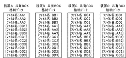
図3は、図2に示した共有ファイル格納部1406に格納されているデータファイルの一例を名とネットワークパス情報の一覧で示したものである。
FIG. 3 shows an example of a data file stored in the shared
本実施形態において、共有ファイル格納部1406に格納されているデータファイルは、ファイル名(file name)とデータファイルが格納されているネットワーク上のパス情報(network pass)等を付帯情報として有する。本実施形態の共有ファイル格納部1406は、図3に示すように、ファイル名とパス情報等を用いて、共有ファイル格納部1406に格納されているデータファイルを管理する。また、制御部1404は、上記ファイル名とパス情報等(後述するファイル情報)を外部装置又は操作パネル1408に表示させて、共有ファイル格納部1406に格納されているデータファイルへのアクセスを受け付ける。
In the present embodiment, the data file stored in the shared
図3において、201は装置A(101)に格納されているデータファイルをファイルの例を名とパス情報の一覧で示したものである。即ち、装置A(101)の共有ファイル格納部1406には、ファイル名「AA1」,「AA2」,「AA3」のデータファイルが格納されている。
In FIG. 3, reference numeral 201 denotes an example of a data file stored in the apparatus A (101) in a list of name and path information. That is, data files with file names “AA1”, “AA2”, and “AA3” are stored in the shared
また、202、203、204はそれぞれ、装置B(102)、装置C(103)、装置D(104)に格納されているデータファイルの例を名とパス情報の一覧で示したものである。即ち、装置B(102)の共有ファイル格納部1406には、ファイル名「BB1」,「BB2」,「BB3」のファイルが格納されている。また、装置C(103)の共有ファイル格納部1406には、ファイル名「CC1」,「CC2」,「CC3」のファイルが格納されている。また、装置D(104)の共有ファイル格納部1406には、ファイル名「DD1」,「DD2」,「DD3」のファイルが格納されている。
Reference numerals 202, 203, and 204 respectively show examples of data files stored in the device B (102), the device C (103), and the device D (104) in a list of names and path information. That is, files with the file names “BB1”, “BB2”, and “BB3” are stored in the shared
なお、データファイルのデータ管理形式に関しては、特にこの形式に限定されるものではない。パス情報に関しても、例えばIPアドレス等、データファイルが格納されている装置の場所が特定できるものであれば、その他の何らかの情報でもよい。 The data file data management format is not particularly limited to this format. Regarding the path information, any other information may be used as long as the location of the device in which the data file is stored can be specified, such as an IP address.
図4は、各デジタル複合機の共有ファイル格納部1406に格納されている共有ファイル(データファイル)の状態を示す概念図である。
FIG. 4 is a conceptual diagram showing a state of a shared file (data file) stored in the shared
なお、図4(a)は、各デジタル複合機が起動している状態の各装置内に格納されている共有ファイルの状態を概念的に示すものである。 FIG. 4A conceptually shows the state of the shared file stored in each apparatus in a state where each digital multifunction peripheral is activated.
また、図4(b)は、図4(a)の状態から装置A(101)がスリープ状態に移行する際のデータ授受を説明するものである。 FIG. 4B illustrates data exchange when the device A (101) shifts from the state of FIG. 4A to the sleep state.
本実施形態では、装置A(101)がスリープ状態に移行する際に、装置A(101)は、装置B(102)に対して、ファイルの実体ではなくファイル名及びネットワーク上のパス情報等のファイルを特定できる特定情報を送信する。なお、上記特定情報を、以下、「一部情報」又は「ファイル情報」という。上記送信処理により、装置A(101)がスリープ状態になっても、装置B(102)が代理で、装置A(101)に格納されているファイルのファイル情報を表示可能となる。さらに、このファイル情報に基づいて、装置B(102)は代理で、装置A(101)に格納されているファイルへのアクセスを受け付け可能となる。なお、ファイル情報としては、ファイルが作成された日時の情報、ファイル作成者の情報、ファイルサイズ、ページ数、サムネイル画像等のその他の情報を含んでいてもよい。 In the present embodiment, when the device A (101) shifts to the sleep state, the device A (101) sends the device B (102) the file name, the path information on the network, etc. Send specific information that can identify the file. The specific information is hereinafter referred to as “partial information” or “file information”. By the above transmission processing, even when the device A (101) goes into the sleep state, the device B (102) can act as a proxy and display the file information of the file stored in the device A (101). Furthermore, on the basis of this file information, the device B (102) can accept access to the file stored in the device A (101) as a proxy. Note that the file information may include other information such as information on the date and time when the file was created, file creator information, file size, number of pages, thumbnail images, and the like.
また、図4(c)は、さらに装置C(103)、装置D(104)もスリープ状態に移行して、装置B(102)だけが、その他の装置の代理で全ファイルのファイル情報を表示可能な状況を示している。なお、この場合も、装置B(102)は、装置C(103)、装置D(104)から送信されたファイル情報に基づいて、代理で、装置A(101)、装置C(103)、装置D(104)に格納されているファイルへのアクセスの受け付け可能である。 Further, in FIG. 4C, the devices C (103) and D (104) also shift to the sleep state, and only the device B (102) displays the file information of all files on behalf of the other devices. Indicates a possible situation. In this case as well, the device B (102) acts as a proxy for the device A (101), the device C (103), and the device based on the file information transmitted from the devices C (103) and D (104). Access to the file stored in D (104) can be accepted.
以下、図5を参照して、本発明のデジタル複合機がスリープ状態に入る際の処理について説明する。 Hereinafter, with reference to FIG. 5, a process when the digital multi-function peripheral according to the present invention enters the sleep state will be described.
図5は、本実施形態のデジタル複合機がスリープ状態に入る際の処理を示すフローチャートである。なお、このフローチャートの処理は、制御部1404のCPUが制御部1404のROMに格納されるプログラムを読み出して実行することにより実現されるものである。
FIG. 5 is a flowchart showing processing when the digital multi-function peripheral of this embodiment enters the sleep state. Note that the processing of this flowchart is realized by the CPU of the
まず、制御部1404のCPUは、スリープ条件を満たしたか監視し、スリープ条件を満たしたと判断した場合に、本フローチャートの処理を開始する(S401)。
First, the CPU of the
まず、ステップS402において、制御部1404のCPUは、同一ネットワーク内に接続されている他の装置が立ち上がっている(起動状態(Standby中))かどうかを判断する。そして、上記ステップS402において、他の装置が立ち上がっていると判断した場合(Yesの場合)、制御部1404のCPUは、ステップS403に処理を進める。
First, in step S402, the CPU of the
ステップS403では、制御部1404のCPUは、立ち上がっている装置が複数台あるかどうかを判断する。そして、上記ステップS403において、立ち上がっている装置が複数台あると判断した場合(Yesの場合)、制御部1404のCPUは、ステップS405に処理を進める。
In step S403, the CPU of the
ステップS405では、制御部1404のCPUは、データ格納部1405に格納されている電力管理テーブル(図6)を参照して、立ち上がっている(Standby中の)装置の中でもっとも待機電力レベルの低い装置を選択する。そして、ステップS407へ処理を進める。
In step S405, the CPU of the
一方、上記ステップS403において、立ち上がっている装置が1台しかないと判断した場合(Noの場合)、制御部1404のCPUは、その装置を選択して、ステップS407へ処理を進める。
On the other hand, when it is determined in step S403 that there is only one device standing up (in the case of No), the CPU of the
また、上記ステップS402において、他の装置が立ち上がっていない、つまりファイル共有機能を有する装置が同一ネットワークグループ上に自装置1台しかない場合(Noの場合)、制御部1404のCPUは、ステップS404に処理を進める。
In step S402, if no other device is started up, that is, if there is only one device having the file sharing function in the same network group (in the case of No), the CPU of the
ステップS404では、制御部1404のCPUは、データ格納部1405に格納されている電力管理テーブル(図6)を参照して、ステップS406に処理を進める。
In step S404, the CPU of the
ステップS406では、制御部1404のCPUは、電力管理テーブル(図6)に基づいて、スリープ中の機器の中で待機電力レベルが自装置より低い装置が存在するかどうかを判断する。そして、上記ステップS406において、スリープ中の機器の中で待機電力レベルが自装置より低い装置が存在すると判断した場合(Yesの場合)、制御部1404のCPUは、その装置を選択して、ステップS407に処理を進める。
In step S406, the CPU of the
ステップS407では、制御部1404のCPUは、選択された装置に対して自装置に格納されている情報を送信する。なお、S406で、スリープ中の機器の中で待機電力レベルが自装置より低い装置が複数存在する場合、予め決められた決定順に応じて、上記待機電力レベルが自装置より低い装置の中から、どの装置を起動させるかを決定するものとする。例えば、使用頻度の多い順、共有ファイル格納部1406の空き容量が多い順等の優先順位に基づいて決定する。また、S405で、立ち上がっている装置の中でもっとも待機電力レベルの低い装置が複数存在する場合も、予め決められた決定順に応じて、どの装置を起動させるかを決定するものとする。
In step S407, the CPU of the
次に、ステップS408において、制御部1404のCPUは、スリープ状態に移行して、本フローチャートの処理を終了させる(S409)。
Next, in step S408, the CPU of the
一方、上記ステップS406にて、スリープ中の機器の中で待機電力レベルが自装置より低い装置が存在しないと判断した場合(Noの場合)、制御部1404のCPUは、スリープ状態に移行することなく、本フローチャートの処理を終了させる(S409)。
On the other hand, if it is determined in step S406 that there is no device whose standby power level is lower than the own device among the sleeping devices (in the case of No), the CPU of the
本実施形態においては、上記ステップS405において、電力管理テーブル内の待機電力レベルの小さいものから優先でファイル情報を送信する装置を決定しているが、ファイル情報送信先の決定方法は、これに限定されるものではない。例えば、アクセス頻度の大小、共有ファイル格納部1406の空き容量の大きい順など、予め設定されて電力管理テーブルで管理されているその他基準に基づいて、データ情報を送信する装置を決定する構成であってもよい。
In the present embodiment, in step S405 described above, a device that transmits file information is determined with priority from the lowest standby power level in the power management table, but the method for determining the file information transmission destination is limited to this. Is not to be done. For example, the configuration is such that a device that transmits data information is determined based on other criteria that are set in advance and managed in the power management table, such as the order of access frequency and the order in which the free capacity of the shared
図6は、データ格納部1405に記憶される電力管理テーブルの一例を示す図である。
FIG. 6 is a diagram illustrating an example of a power management table stored in the
図6に示すように、電力管理テーブルは、装置A〜Dそれぞれの待機電力ランク、共有ファイル格納部1406の空き容量、ステータス情報、及び、図示しない他の情報を含んでいる。
As shown in FIG. 6, the power management table includes the standby power rank of each of the devices A to D, the free capacity of the shared
なお、待機電力ランクは、装置の待機電力について、ある一定の範囲を持たせて1,2,3のランク付けをしたものである。本実施形態においては、待機電力ランクは、1<2<3のように待機電力値の大きさが定義されている。 The standby power rank is a ranking of 1, 2, and 3 with a certain range for the standby power of the apparatus. In the present embodiment, the standby power rank is defined such that the standby power value is 1 <2 <3.
また、ステータス情報は、装置がスタンバイ状態にあるかスリープ状態にあるかを示すものである。さらに、共有BOXの空き容量は、共有ファイル格納部1406(以下、「共有BOXフォルダ」という)の空き容量を示すものである。 The status information indicates whether the apparatus is in a standby state or a sleep state. Furthermore, the free capacity of the shared BOX indicates the free capacity of the shared file storage unit 1406 (hereinafter referred to as “shared BOX folder”).
以下、図7を用いて図6に示した電力管理テーブルの生成方法を説明する。 Hereinafter, a method for generating the power management table shown in FIG. 6 will be described with reference to FIG.
図7は、本実施形態における電力管理テーブル生成方法の一例を示すフローチャートである。なお、このフローチャートの処理は、制御部1404のCPUが制御部1404のROMに格納されるプログラムを読み出して実行することにより実現されるものである。
FIG. 7 is a flowchart illustrating an example of a power management table generation method according to the present embodiment. Note that the processing of this flowchart is realized by the CPU of the
なお、ネットワークに接続されているファイル共有機能を有する各装置は、データ格納部1405内に電力管理テーブルを有しており、初めてネットワークに接続する場合には、図8のように予め自装置の管理テーブルのみを有する。
Each device connected to the network and having a file sharing function has a power management table in the
図8は、デジタル複合機が初めてネットワークに接続する際にデータ格納部1405に記憶される電力管理テーブルの一例を示す図である。
FIG. 8 is a diagram illustrating an example of a power management table stored in the
以下、図7の各ステップについて説明する。 Hereinafter, each step of FIG. 7 will be described.
デジタル複合機が起動され、制御部1404のCPUが、ネットワークに接続されたことを検知すると、本フローチャートの処理を開始する(S501)。
When the digital multifunction peripheral is activated and the CPU of the
まず、ステップS1502において、制御部1404のCPUは、ネットワークに接続されている他装置を検出し、該検出結果に基づいて、ステップS1503において、ネットワークに他装置が接続されているか否かを判断する。
First, in step S1502, the CPU of the
そして、上記ステップS1503において、ネットワークに他装置が接続されていないと判断した場合(Noの場合)、制御部1404のCPUは、そのまま本フローチャートの処理を終了させる(S1510)。
When it is determined in step S1503 that no other device is connected to the network (in the case of No), the CPU of the
一方、上記ステップS1503において、ネットワークに他装置が接続されていると判断した場合(Yesの場合)、制御部1404のCPUは、ステップS1504に処理を進める。
On the other hand, if it is determined in step S1503 that another device is connected to the network (Yes), the CPU of the
ステップS1504では、制御部1404のCPUは、ネットワークに接続されている全ての他装置の情報が既に電力管理テーブルに格納されているか否かを判断する。そして、上記ステップS1504において、ネットワークされている他装置のうち未だ情報が電力管理テーブルに格納されていないものがあると判断した場合(Noの場合)、制御部1404のCPUは、ステップS1505に処理を進める。
In step S1504, the CPU of the
ステップS1505では、制御部1404のCPUは、未だ電力管理テーブルに情報が格納されていないいずれかの他装置(以下、該当装置)と通信して、該当装置からその装置の情報を受信して電力管理テーブルに追加する。そして、ステップS1504に処理を戻し、上記ステップS1504,S1505の処理を、ネットワークに接続されている全ての他装置の情報が電力管理テーブルに格納されるまで繰り返す。
In step S <b> 1505, the CPU of the
そして、上記ステップS1504において、ネットワークされている全ての他装置の情報が既に電力管理テーブルに格納されていると判断した場合(Yesの場合)、制御部1404のCPUは、ステップS1506に処理を進める。
If it is determined in step S1504 that information on all other devices networked is already stored in the power management table (Yes), the CPU of the
ステップS1506では、制御部1404のCPUは、電力管理テーブルに登録されているいずれかの他装置(以下、該当装置)と通信して(要求して)、該当装置から送信されるその装置の情報(待機電力情報を含む)を受信する。そして、制御部1404のCPUは、前記受信した該当装置の待機電力情報と、電力管理テーブルに登録されている該当装置の待機電力情報とを比較し、ステップS1507に処理を進める。
In step S1506, the CPU of the
ステップS1507では、制御部1404のCPUは、上記ステップS1506の比較結果に基づいて、受信した該当装置の待機電力情報と電力管理テーブルに登録されている該当装置の待機電力情報とが異なるか否かを判断する。
In step S1507, the CPU of the
上記ステップS1507において、前記受信した待機電力情報と電力管理テーブルに登録されている待機電力情報とが異なると判断した場合(Yesの場合)、制御部1404のCPUは、装置構成が変更されたと判断し、ステップS1508に処理を進める。
If it is determined in step S1507 that the received standby power information is different from the standby power information registered in the power management table (Yes), the CPU of the
ステップS1508では、制御部1404のCPUは、前記受信した該当装置の情報に応じて電力管理テーブルを更新し、ステップS1509に処理を進める。
In step S1508, the CPU of the
一方、上記ステップS1507において、前記受信した待機電力情報と電力管理テーブルに登録されている待機電力情報とが等しいと判断した場合(Noの場合)、制御部1404のCPUは、そのままステップS1509に処理を進める。
On the other hand, when it is determined in step S1507 that the received standby power information is equal to the standby power information registered in the power management table (in the case of No), the CPU of the
ステップS1509では、制御部1404のCPUは、上記S1506〜S1508の処理を、ネットワークに接続されている全ての他装置について終了したか判断する。そして、上記ステップS1509において、まだ終了していないと判断した場合(Noの場合)、制御部1404のCPUは、ステップS1506に処理を戻す。
In step S1509, the CPU of the
一方、上記ステップS1509において、上記S1506〜S1508の処理を、ネットワークに接続されている全ての他装置について終了したと判断した場合(Yesの場合)、制御部1404のCPUは、本フローチャートの処理を終了させる(S1510)。なお、電力管理テーブル情報の取得方法は、図7に示した方法に限定されるものではない。例えば、他装置から他装置が保持する電力管理テーブルをそのまま受け取るように構成してもよい。
On the other hand, if it is determined in step S1509 that the processing in steps S1506 to S1508 has been completed for all other devices connected to the network (in the case of Yes), the CPU of the
また、本フローチャートを終了する前に、制御部1404のCPUは、自装置の待機電力情報を起動状態の全ての装置に送信するようにしてもよい。
Further, before ending this flowchart, the CPU of the
以下、図9を参照して、スタンバイ中の装置がスリープ状態に移行する装置からファイル情報を受け取る際の処理及びその後の処理について説明する。 Hereinafter, with reference to FIG. 9, a process when the standby apparatus receives file information from the apparatus that shifts to the sleep state and the subsequent process will be described.
図9は、スタンバイ中の装置がスリープ状態に移行する装置からファイル情報を受け取る際の処理を示すフローチャートを示す。特に、図9(a)は、スタンバイ中の装置がスリープ状態に移行する装置からファイル情報を受け取る際の処理を示す。また、図9(b)は、装置内に格納中のファイル情報に外部装置からアクセスされた際の処理について示す。 FIG. 9 is a flowchart showing processing when the standby apparatus receives file information from the apparatus that shifts to the sleep state. In particular, FIG. 9A shows processing when a standby apparatus receives file information from an apparatus that shifts to a sleep state. FIG. 9B shows processing when file information stored in the apparatus is accessed from an external apparatus.
制御部1404のCPUは、ネットワークを介して他装置から自装置へファイル情報が送信されてきたこと(例えば、図5のS407の送信)を検知すると、図9(a)の処理を開始する(S601)。
When the CPU of the
まず、ステップS602において、制御部1404のCPUは、他装置(即ち、スリープ状態に移行する装置)から送信されたファイル情報(例えば、図5のS407で送信されたファイル情報)を受信処理する。
First, in step S602, the CPU of the
次に、ステップS603において、制御部1404のCPUは、上記ステップS602で受信したファイル情報を共有BOXフォルダに格納し、図9(a)の処理を終了させる(S604)。このファイル情報に基づいて、制御部1404のCPUは、上記他装置がスリープ状態に入っていても、代理で、他装置に格納されているファイルのファイル情報を表示可能となる。さらに、このファイル情報に基づいて、制御部1404のCPUは、代理で、他装置に格納されているファイルへのアクセスを受け付け可能となる。
Next, in step S603, the CPU of the
また、制御部1404のCPUは、装置の起動後、図9(b)の処理を開始する(S605)。
Further, the CPU of the
まず、ステップS606において、制御部1404のCPUは、自装置内の共有BOXフォルダに格納されているファイル情報に外部装置からアクセスされたと判断した場合(Yesの場合)、ステップS607に処理を進める。なお、上述したように、制御部1404は、自装置に格納されているデータファイルのファイル情報と、他装置から受信したファイル情報(自装置には実体がないファイル情報)を外部装置等に表示させて、データファイルへのアクセスを受け付けている。そのため、上記アクセスされたファイル情報は、自装置に実体のあるデータファイルのファイル情報のみならず、他装置に実体のあるデータファイルのファイル情報である可能性がある。
First, in step S606, when the CPU of the
次に、ステップS607では、制御部1404のCPUは、ステップS605でアクセス検知されたファイル情報の実体が他装置にある(即ち、図9(a)で受信・格納し、他装置の代理でアクセスを受け付けているもの)かどうか判断する。
Next, in step S607, the CPU of the
そして、上記ステップS607において、アクセス検知されたファイル情報の実体が他装置にあると判断した場合(Yesの場合)、ステップS608に処理を進める。 If it is determined in step S607 that the actual file information whose access has been detected exists in another device (Yes), the process proceeds to step S608.
ステップS608では、制御部1404のCPUは、ファイルの実体が存在する装置をスリープ(Sleep)状態から起動させてよいかどうかをアクセスされた外部装置(アクセス元)に通知する(問い合わせる)。
In step S608, the CPU of the
次に、ステップS609において、制御部1404のCPUは、前記アクセスされた外部装置からの回答(応答)を待機し、前記アクセスされた外部装置からOKの応答(スリープから起動させてよい旨の応答)があったかどうか判断する。
Next, in step S609, the CPU of the
そして、上記ステップS609において、前記アクセスされた外部装置からOKの回答(スリープから起動させてよい旨の応答)がなかった判断した場合(Noの場合)、制御部1404のCPUは、そのまま図9(b)の処理を終了させる(S613)。即ち、前記アクセスされた外部装置からNGの回答(スリープから起動させない旨の応答)があった場合や、予め決められた時間内に前記アクセスされた外部装置から回答(応答)がなかった場合、処理を終了させる。
If it is determined in step S609 that the accessed external device has not received an OK response (response indicating that the device can be activated from sleep) (in the case of No), the CPU of the
一方、上記ステップS609において、前記アクセスされた外部装置からOKの回答(スリープから起動させてよい旨の応答)があったと判断した場合(Yesの場合)、制御部1404のCPUは、ステップS610に処理を進める。
On the other hand, if it is determined in step S609 that the accessed external device has received an OK response (response indicating that it can be activated from sleep) (in the case of Yes), the CPU of the
ステップS610では、制御部1404のCPUは、前記アクセスされたファイルの実体を保管している装置(上記他装置)に対してWake Upコマンドを送信する(他装置起動処理)。なお、このWake Upコマンドを受信したデジタル複合機は、スリープ状態からスタンバイ状態(起動状態)に復帰することとなる。
In step S610, the CPU of the
次に、ステップS611において、制御部1404のCPUは、前記アクセスされたファイルの実体を保管している装置がスタンバイ(Standby)状態になるまで待機する。そして、その装置がスタンバイ(Standby)状態になったら、制御部1404のCPUは、その装置に対して、外部装置からその装置が保管しているファイルにアクセスされた旨を通知する(そのファイルのファイル情報も通知)。そして、図9(b)の処理を終了させる(S613)。
Next, in step S611, the CPU of the
なお、本フローチャートでは、外部装置からのアクセスがあった場合を例にして説明したが、自装置の操作パネル1408から直接、所望のファイルにアクセスがあった場合にも同様の処理を行うものとする。
In this flowchart, the case where there is an access from an external device has been described as an example. However, the same processing is performed when a desired file is accessed directly from the
図10は、共有BOX内のデータファイルの格納状況を示す操作パネル1408の表示画面の一例を示す図である。
FIG. 10 is a view showing an example of a display screen of the
本実施形態では、装置B(102)の中にあるファイルを表示しており、装置A(101)、装置C(103)が双方とも装置B(102)に対してファイル情報を送信してスリープ状態に入っていることを示している。 In the present embodiment, a file in the device B (102) is displayed, and both the device A (101) and the device C (103) transmit file information to the device B (102) to sleep. Indicates that it is in a state.
なお、図10中、「AA1」,「AA2」は、装置A(101)に実体が保管されているデータファイルを示す。「BB1」は、自装置(即ち装置B(102))に実体が保管されているデータファイルを示す。また、「CC1」は、装置C(103)に実体が保管されているデータファイルを示す。 In FIG. 10, “AA1” and “AA2” indicate data files whose entities are stored in the device A (101). “BB1” indicates a data file in which the entity is stored in its own device (ie, device B (102)). “CC1” indicates a data file whose entity is stored in the device C (103).
なお、ユーザは、この図10の表示画面から、データファイルへのアクセス操作が可能である。 The user can access the data file from the display screen of FIG.
図11は、図10の表示画面でファイルの中からスリープ状態にある装置A内に格納されているファイル名「AA2」というファイルを選択した際の動作を示す図である。 FIG. 11 is a diagram showing an operation when the file named “AA2” stored in the device A in the sleep state is selected from the files on the display screen of FIG.
この場合に、装置B(102)の制御部1404のCPUは、ファイル「AA2」を操作するためには、スリープ中の装置Aを起動させる必要があるため、起動させてもよいかどうか選択させる画面801(問い合せ画面)を表示させている。この表示は、装置B(102)の制御部1404のCPUが、図9(b)のS608の通知を受け取ったことに応じて行うものとする。
In this case, since the CPU of the
なお、画面801において、「はい」ボタン802が指示された場合、装置B(102)の制御部1404のCPUは、図9(b)のS608の通知の送信元に、OKの回答(スリープから起動させてよい旨の回答)を通知する。そして、図12の画面を操作パネル1408に表示する。
When the “Yes”
一方、「いいえ」ボタン803が指示された場合、装置B(102)の制御部1404のCPUは、図16(b)のS608の通知の送信元に、NGの回答(スリープから起動させない旨の回答)を通知する。
On the other hand, when the “No”
図12は、図11の画面801で「はい」ボタン802が押下されて装置Aをスリープから起動させた場合の操作パネルの画面を示す図である。この場合に、装置A,装置Bとも同等の画面を表示するものとする。
FIG. 12 is a diagram showing a screen of the operation panel when the “Yes”
以上示したように、本実施形態によれば、ファイル共有機能を実現しつつ、個々のデジタル複合機が自由にスリープに移行できる仕組みを設けることにより、消費電力の削減が見込める。さらに、最後に残った装置がスリープ状態に移行する際には、自装置よりも待機電力の低い装置に代理させることで、さらに良好な省電力状態を保つことが可能となる。 As described above, according to the present embodiment, it is possible to reduce power consumption by providing a mechanism that allows each digital multi-function peripheral to freely shift to sleep while realizing a file sharing function. Furthermore, when the last remaining device shifts to the sleep state, it is possible to maintain a better power saving state by using a device having lower standby power than the own device as a proxy.
〔第2実施形態〕
上記第1実施形態では、操作パネル1408上に図10〜図12に示す表示されることを想定して説明した。しかし、その他、パーソナルコンピュータ(PC)などからリモート操作できる構成で、リモートUI上にドライバで表示させるような方法も考えられる。以下、この構成を第2実施形態として説明する。
[Second Embodiment]
The first embodiment has been described on the assumption that the screen shown in FIGS. 10 to 12 is displayed on the
図13は、本発明の第2実施形態を示すデータ格納装置を適用可能なデジタル複合機を含むシステムの構成の一例を示すシステム構成図であり、図1と同一のものには同一の符号を付してある。 FIG. 13 is a system configuration diagram showing an example of a system configuration including a digital multi-function peripheral to which the data storage device according to the second embodiment of the present invention can be applied. The same components as those in FIG. It is attached.
図13において、1801はパーソナルコンピュータ(PC)である。本実施形態では、ユーザAがPC1801からファイル共有機能を操作することも可能である。
In FIG. 13,
図14は、図13に示したPC1801からファイル共有機能で共有BOXフォルダを開いた際の操作画面1900の一例を示す図である。
FIG. 14 is a diagram showing an example of an
PC1801からファイル共有機能を用いて共有BOXフォルダを開くと、まず、図14に示す画面1900が表示される。ユーザは、この画面1900から、1901に示すように、問い合わせをする装置を選択することができる。
When a shared BOX folder is opened from the
本実施形態では、Standby状態の装置にのみ問合せ可能とし、ユーザAはStandby中の「装置B」若しくは、「装置C」を選択可能である。図14に示した例では、1901に示すように、「装置B」が問合せをする装置に選択されている。この状態で、詳細情報ボタン1902が指示されると、図15に示す画面2000が表示される。
In this embodiment, it is possible to make an inquiry only to a device in the standby state, and the user A can select “device B” or “device C” in standby. In the example illustrated in FIG. 14, as illustrated in 1901, “device B” is selected as a device to make an inquiry. In this state, when a
図15は、装置Bを選択した際にPC1801上に表示される選択画面2000の一例を示す図である。
FIG. 15 is a diagram illustrating an example of a
図15に示すように、選択画面2000では、装置B内に格納されているファイル情報が操作可能に表示される。なお、装置B内に格納されているスリープ中の他装置のファイル情報も操作可能となる。
As shown in FIG. 15, on the
以上説明したように、本実施形態によれば、PC1801からもファイル共有機能を用いて共有BOXフォルダに格納されたファイル情報を閲覧できるので、不用意にデジタル複合機のスリープ状態が解除されることもなく、省電力状態を保つことが可能となる。例えば、ユーザがファイル共有機能を使用するため、他に起動中のデジタル複合機があるにもかかわらず、自分の席の近くにあるスリープ中のデジタル複合機を起動させて、電力を浪費させてしまうといった事態の発生を抑えることができる。
As described above, according to the present embodiment, since the file information stored in the shared BOX folder can be browsed from the
〔第3実施形態〕
上記第1実施形態では、各デジタル複合機はスリープ状態に入る前に自装置の共有BOXフォルダ内のファイル情報を他の装置に送信する構成について説明した。しかし、各デジタル複合機をネットワークに接続させて起動させた時に相互間で共有BOXフォルダ内のファイル情報の送受信を行うように構成してもよい。以下、この構成を第3実施形態として説明する。
[Third Embodiment]
In the first embodiment, the configuration has been described in which each digital multifunction peripheral transmits the file information in the shared BOX folder of its own device to another device before entering the sleep state. However, the file information in the shared BOX folder may be transmitted / received between the digital multifunction peripherals when connected to the network and activated. Hereinafter, this configuration will be described as a third embodiment.
図16は、本発明の第3実施形態を示す各デジタル複合機のそれぞれが共有BOXフォルダ内に格納している格納データの概念図である。 FIG. 16 is a conceptual diagram of stored data stored in a shared BOX folder by each digital multi-function peripheral according to the third embodiment of the present invention.
本実施形態においては、各デジタル複合機をネットワークに接続させて起動させた時に相互間で共有BOXフォルダ内のファイル情報の送受信を行う。 In this embodiment, when each digital multi-function peripheral is connected to a network and activated, file information in the shared BOX folder is transmitted and received between them.
ここで、ファイル情報(特定情報)とは、ファイルの実体ではなく、ファイル名やファイル実体の格納先が特定できるネットワークパス情報などの付加情報を含み、その他、サムネイル画像など比較的容量の小さいファイルの情報の一部を含んでいてもよい。 Here, the file information (specific information) is not a file entity but includes additional information such as network path information that can specify the file name and the storage location of the file entity, and other files with a relatively small capacity such as thumbnail images. A part of the information may be included.
図17は、図16の状態から相互装置間で共有BOXフォルダ内のファイル情報の送受信を行った結果、各々の装置が各装置の共有BOXフォルダ内に他装置のファイル情報を格納している状態を示す図である。 FIG. 17 shows a state in which each device stores file information of another device in the shared BOX folder of each device as a result of transmission / reception of file information in the shared BOX folder between the devices from the state of FIG. FIG.
図18は、図17の状態から装置A、装置C、装置Dがスリープに入ったために装置Bだけがその他の装置の代理で全ファイル情報を格納している状態を示す図である。 FIG. 18 is a diagram illustrating a state in which only the device B stores all file information on behalf of other devices because the devices A, C, and D have entered the sleep state from the state of FIG.
なお、装置A,C,Dがスリープ状態に移行する際には、それぞれに格納されていた他装置のファイル情報を消去するものとする。 When the devices A, C, and D shift to the sleep state, the file information of the other devices stored in each device is deleted.
以下、図19,図20を参照して、本発明の第3実施形態を示すデジタル複合機の処理を説明する。 Hereinafter, with reference to FIGS. 19 and 20, the processing of the digital multi-function peripheral according to the third embodiment of the present invention will be described.
図19は、本実施形態のデジタル複合機が起動時にネットワーク接続されている他装置に対してファイル情報を送信する処理の一例を示すフローチャートである。なお、このフローチャートの処理は、制御部1404のCPUが制御部1404のROMに格納されるプログラムを読み出して実行することにより実現されるものである。
FIG. 19 is a flowchart illustrating an example of processing for transmitting file information to another apparatus connected to the network when the digital multi-function peripheral according to the present embodiment is activated. Note that the processing of this flowchart is realized by the CPU of the
デジタル複合機が起動され、制御部1404のCPUが、ネットワークに接続されたことを検知すると、本フローチャートの処理を開始する(S1201)。
When the digital multifunction peripheral is activated and the CPU of the
まず、ステップS1202において、制御部1404のCPUは、ネットワークに接続されているファイル共有機能を持つ他の装置が起動している状態にあるかどうかを確認する。そして、上記ステップS1202において、他の装置が起動している状態にないと判断した場合(Noの場合)、制御部1404のCPUは、そのまま本フローチャートの処理を終了させる(S1206)。
First, in step S1202, the CPU of the
一方、上記ステップS1202において、他の装置が起動している状態にあると判断した場合(Yesの場合)、制御部1404のCPUは、ステップS1203に処理を進める。
On the other hand, if it is determined in step S1202 that the other device is in the activated state (in the case of Yes), the CPU of the
ステップS1203では、制御部1404のCPUは、起動している全てのファイル共有機能を持つ他の装置から電力レベル情報を取得して待機電力管理テーブルを生成する。
In step S1203, the CPU of the
次に、ステップS1204において、制御部1404のCPUは、起動している他装置に対して自装置の共有BOXフォルダに格納されているファイル情報を送信する(起動時送信処理)。
Next, in step S1204, the CPU of the
続いて、ステップS1205において、制御部1404のCPUは、起動している他の装置と通信して(要求して)、他の装置から送信されるファイル情報を受信する(起動時受信処理)。そして、本フローチャートの処理を終了させる(S1206)。
Subsequently, in step S1205, the CPU of the
なお、上記ステップS1204とステップS1205の順序はどちらが先でも構わない。また、送受信される前記ファイル情報とは、共有BOXフォルダに入っているファイルのファイル名を含む一部の情報とネットワークのパス情報若しくはIPアドレスなど格納場所を特定可能な情報を付加情報として含んでいるものとする。 Note that the order of step S1204 and step S1205 may be either. The file information to be transmitted / received includes, as additional information, information that can specify a storage location such as part of information including the file name of a file in the shared BOX folder and network path information or IP address. It shall be.
以下、図20を参照して、本実施形態のデジタル複合機がスリープ状態に入る際の処理について説明する。 Hereinafter, with reference to FIG. 20, a process when the digital multi-function peripheral according to the present embodiment enters the sleep state will be described.
図20は、本実施形態のデジタル複合機がスリープ状態に入る際の処理を示すフローチャートである。なお、このフローチャートの処理は、制御部1404のCPUが制御部1404のROMに格納されるプログラムを読み出して実行することにより実現されるものである。
FIG. 20 is a flowchart illustrating processing when the digital multi-function peripheral according to the present embodiment enters the sleep state. Note that the processing of this flowchart is realized by the CPU of the
まず、制御部1404のCPUは、スリープ条件を満たしたか監視し、スリープ条件を満たしたと判断した場合に、本フローチャートの処理を開始する(S1301)。
First, the CPU of the
まず、ステップS1302において、制御部1404のCPUは、同一ネットワーク内に接続されている他の装置が立ち上がっている(起動状態(Standby中))かどうかを判断する。そして、上記ステップS1302において、他の装置が立ち上がっていると判断した場合(Yesの場合)、制御部1404のCPUは、ステップS1303に処理を進める。
First, in step S1302, the CPU of the
ステップS1303では、制御部1404のCPUは、立ち上がっている装置が複数台あるかどうかを判断する。そして、上記ステップS1303において、立ち上がっている装置が複数台あると判断した場合(Yesの場合)、制御部1404のCPUは、ステップS1305に処理を進める。
In step S1303, the CPU of the
ステップS1305では、制御部1404のCPUは、データ格納部1405に格納されている電力管理テーブル(図6)を参照して、立ち上がっている(Standby中の)装置の中でもっとも待機電力レベルの低い装置を選択する。そして、ステップS1307へ処理を進める。
In step S1305, the CPU of the
一方、上記ステップS1303において、立ち上がっている装置が1台しかないと判断した場合(Noの場合)、制御部1404のCPUは、その装置を選択し、ステップS1307へ処理を進める。
On the other hand, if it is determined in step S1303 that there is only one device standing up (in the case of No), the CPU of the
また、上記ステップS1302において、他の装置が立ち上がっていない、つまりファイル共有機能を有する装置が同一ネットワークグループ上に自装置1台しかない場合(Noの場合)、制御部1404のCPUは、ステップS1304に処理を進める。
In step S1302, if no other device is started up, that is, if there is only one device having the file sharing function in the same network group (in the case of No), the CPU of the
ステップS1304では、制御部1404のCPUは、データ格納部1405に格納されている電力管理テーブル(図6)を参照して、ステップS1306に処理を進める。
In step S1304, the CPU of the
ステップS1306では、制御部1404のCPUは、電力管理テーブル(図6)に基づいて、スリープ中の機器の中で待機電力レベルが自装置より低い装置が存在するかどうかを判断する。そして、上記ステップS1306において、スリープ中の機器の中で待機電力レベルが低い装置が存在すると判断した場合(Yesの場合)、制御部1404のCPUは、その装置を選択して、ステップS1307に処理を進める。
In step S1306, the CPU of the
ステップS1307では、制御部1404のCPUは、選択された装置に対して自装置に格納されている情報を送信する。なお、S1306で、スリープ中の機器の中で待機電力レベルが自装置より低い装置が複数存在する場合、予め決められた決定順に応じて、上記待機電力レベルが自装置より低い装置の中から、どの装置を起動させるかを決定するものとする。例えば、使用頻度の多い順、共有ファイル格納部1406の空き容量が多い順等の優先順位に基づいて決定する。また、S1305で、立ち上がっている装置の中でもっとも待機電力レベルの低い装置が複数存在する場合も、予め決められた決定順に応じて、どの装置を起動させるかを決定するものとする。
In step S1307, the CPU of the
また、上記ステップS1307で送信する、自装置に格納されている情報とは、自装置内にデータファイルの実体が格納されているファイル情報のみを示している。即ち、他装置にデータファイルの実体が格納されているファイル情報(他装置から収集したファイル情報)は含まないものとする。 Further, the information stored in the own device transmitted in step S1307 indicates only file information in which the substance of the data file is stored in the own device. That is, it is assumed that file information (file information collected from another device) in which the substance of the data file is stored in the other device is not included.
次に、ステップS1308において、制御部1404のCPUは、前記他装置から収集したファイル情報を削除し、ステップS1309に処理を進める。
Next, in step S1308, the CPU of the
ステップS1309では、制御部1404のCPUは、スリープ状態に移行して、本フローチャートの処理を終了させる(S1310)。
In step S1309, the CPU of the
一方、上記ステップS1306にて、スリープ中の機器の中で待機電力レベルが自装置より低い装置が存在しないと判断した場合(Noの場合)、制御部1404のCPUは、スリープ状態に移行することなく、本フローチャートの処理を終了させる(S1310)。
On the other hand, if it is determined in step S1306 that there is no device whose standby power level is lower than the own device among the devices in the sleep state (in the case of No), the CPU of the
本実施形態においては、上記ステップS1305において、電力管理テーブル内の待機電力レベルの小さいものから優先でファイル情報を送信する装置を決定しているが、ファイル情報送信先の決定方法は、これに限定されるものではない。例えば、アクセス頻度の大小、共有BOXフォルダ空き容量の大きい順など、予め設定されて電力管理テーブルで管理されているその他基準に基づいて、データ情報を送信する装置を決定する構成であってもよい。 In the present embodiment, in step S1305, the device that transmits file information is determined with priority from the one with the lowest standby power level in the power management table. However, the method for determining the file information transmission destination is limited to this. Is not to be done. For example, a configuration may be adopted in which a device that transmits data information is determined based on other criteria that are set in advance and managed in the power management table, such as the order of access frequency and the order of the free space in the shared BOX folder. .
また、上記ステップS1305では、立ち上がっている(Standby中の)全ての装置をファイル情報を送信する装置として選択するようにしてもよい。 In step S1305, all the devices that are standing up (in standby) may be selected as devices that transmit file information.
以上説明したように、本実施形態によれば、ファイル共有機能を実現しつつ、個々のデジタル複合機が自由にスリープ状態に入れる仕組みを設けることで、消費電力の削減が見込める。さらに、最後に残った装置がスリープ状態に移行する際には、自装置よりも待機電力の低い装置に代理させることで、さらに良好な省電力状態を保つことが可能となる。 As described above, according to the present embodiment, it is possible to reduce power consumption by providing a mechanism in which each digital multi-function peripheral can freely enter a sleep state while realizing a file sharing function. Furthermore, when the last remaining device shifts to the sleep state, it is possible to maintain a better power saving state by using a device having lower standby power than the own device as a proxy.
なお、図6に示した電力管理テーブルをPCサーバ105に記憶させて、PCサーバ105にて各装置の待機電力レベルを管理するように構成してもよい。この場合、各デジタル複合機は、PCサーバ105から電力管理テーブルを取得して、該取得した電力管理テーブルに基づいて、各装置の待機電力レベルを判断するものとする。また、各デジタル複合機は、装置の構成が変更された際や起動時等に、自装置の待機電力レベルをPCサーバ105に通知するようにしてもよい。
The power management table shown in FIG. 6 may be stored in the
また、PCサーバ105が、各デジタル複合機の状態を統括管理するようにしてもよい。例えば、各デジタル複合機は、スリープ状態に入る前に、PCサーバ105にスリープ状態に移行してよいか問合せる。PCサーバ105は、PCサーバ105が保持する電力管理テーブルに基づいて、問合せのあった装置よりも待機電力の低い装置が存在し、且つ、起動状態の場合には、問合せのあった装置のスリープ状態への移行を許可する。また、PCサーバ105は、問合せのあった装置よりも待機電力の低い装置が存在し、且つ、スリープ状態の場合には、問合せのあった装置のスリープ状態への移行を許可するとともに、最も待機電力の低い装置をスリープ状態から起動させる。
Further, the
なお、スリープ状態への移行を許可されたデジタル複合機は、自装置の共有BOXフォルダ内のファイル情報を、PCサーバ105に送信してスリープ状態へ移行する。そして、ファイル情報を受信したPCサーバ105は、該受信したファイル情報を、上記スリープ移行した装置より待機電力の低い装置に送信するものとする。
In addition, the digital multi-function peripheral permitted to shift to the sleep state transmits the file information in the shared BOX folder of the own device to the
なお、上述した各種データの構成及びその内容はこれに限定されるものではなく、用途や目的に応じて、様々な構成や内容で構成されることは言うまでもない。以上、一実施形態について示したが、本発明は、例えば、システム、装置、方法、プログラム若しくは記憶媒体等としての実施態様をとることが可能である。具体的には、複数の機器から構成されるシステムに適用しても良いし、また、一つの機器からなる装置に適用しても良い。 It should be noted that the configuration and contents of the various data described above are not limited to this, and it goes without saying that the various data and configurations are configured according to the application and purpose. Although one embodiment has been described above, the present invention can take an embodiment as a system, apparatus, method, program, storage medium, or the like. Specifically, the present invention may be applied to a system composed of a plurality of devices, or may be applied to an apparatus composed of a single device.
以上示したように、ネットワークに接続されている共有ファイルシステムを構築する個々の装置がスリープ状態に移行する際には他の装置に自装置内に格納するデータファイルの特定情報(ファイル名等の一部情報)を通知して移行する。なお、最後に残った装置がスリープ状態に移行する際には、より待機電力の少ない他の装置をスリープ状態から復帰させて、自装置内に格納するデータファイルの特定情報を通知して、スリープ状態に移行するように構成する。 As described above, when individual devices constructing the shared file system connected to the network shift to the sleep state, the specific information (such as the file name) of the data file stored in the own device in the other device (Some information) When the last remaining device transitions to the sleep state, the other device with less standby power is returned from the sleep state to notify the specific information of the data file stored in the own device, and Configure to transition to the state.
このように、ファイル共有機能を有効に利用しつつ、不必要な装置は省電力状態に移行することを許可し、最後に残った装置が省電力状態に移行する際は、より待機電力の低い装置に代理させて、システム全体として良好な省電力状態を保つことが可能となる。 Thus, while effectively using the file sharing function, unnecessary devices are allowed to shift to the power saving state, and when the last remaining device shifts to the power saving state, the standby power is lower. It is possible to maintain a good power saving state as a whole system by letting the device substitute.
したがって、ネットワークを介して接続された各データ格納装置間でデータを相互に参照できるファイル共有機能を有するデータ格納装置を含むシステムにおいて、ファイル共有機能を維持しつつ電力の浪費を抑えた最適な省電力システムを構築できる。 Therefore, in a system including a data storage device having a file sharing function that allows data to be mutually referred between each data storage device connected via a network, an optimum saving in which waste of power is suppressed while maintaining the file sharing function. An electric power system can be constructed.
以下、図21に示すメモリマップを参照して、デジタル複合機101〜104を本発明に係るデータ処理装置として機能させるためのプログラムを記録したコンピュータ読み取り可能な記録媒体(記録媒体)のメモリマップの構成について説明する。 Hereinafter, referring to the memory map shown in FIG. 21, a memory map of a computer-readable recording medium (recording medium) recording a program for causing the digital multifunction peripherals 101 to 104 to function as the data processing apparatus according to the present invention will be described. The configuration will be described.
図21は、デジタル複合機101〜104を本発明に係るデータ処理装置として機能させるためのプログラムを記録したコンピュータ読み取り可能な記録媒体(記録媒体)のメモリマップを説明する図である。 FIG. 21 is a diagram for explaining a memory map of a computer-readable recording medium (recording medium) on which a program for causing the digital multifunction peripherals 101 to 104 to function as a data processing apparatus according to the present invention is recorded.
なお、特に図示しないが、記憶媒体に記憶されるプログラム群を管理する情報、例えばバージョン情報,作成者等も記憶され、かつ、プログラム読み出し側のOS等に依存する情報、例えばプログラムを識別表示するアイコン等も記憶される場合もある。 Although not particularly illustrated, information for managing a program group stored in the storage medium, for example, version information, creator, etc. is also stored, and information depending on the OS on the program reading side, for example, a program is identified and displayed. Icons may also be stored.
さらに、各種プログラムに従属するデータも上記ディレクトリに管理されている。また、各種プログラムをコンピュータにインストールするためのプログラムや、インストールするプログラムが圧縮されている場合に、解凍するプログラム等も記憶される場合もある。 Further, data depending on various programs is also managed in the directory. In addition, a program for installing various programs in the computer, and a program for decompressing when the program to be installed is compressed may be stored.
本実施形態における図5,図7,図9,図19,図20に示す機能が外部からインストールされるプログラムによって、ホストコンピュータにより遂行されていてもよい。そして、その場合、CD−ROMやフラッシュメモリやFD等の記憶媒体により、あるいはネットワークを介して外部の記憶媒体から、プログラムを含む情報群を出力装置に供給される場合でも本発明は適用されるものである。 The functions shown in FIGS. 5, 7, 9, 19, and 20 in this embodiment may be performed by a host computer by a program installed from the outside. In this case, the present invention is applied even when an information group including a program is supplied to the output device from a storage medium such as a CD-ROM, a flash memory, or an FD, or from an external storage medium via a network. Is.
以上のように、前述した実施形態の機能を実現するソフトウェアのプログラムコードを記録した記憶媒体を、システムあるいは装置に供給する。そして、そのシステムあるいは装置のコンピュータ(又はCPUやMPU)が記憶媒体に格納されたプログラムコードを読出し実行することによっても、本発明の目的が達成されることは言うまでもない。 As described above, a storage medium storing software program codes for realizing the functions of the above-described embodiments is supplied to a system or apparatus. It goes without saying that the object of the present invention can also be achieved by the computer (or CPU or MPU) of the system or apparatus reading and executing the program code stored in the storage medium.
この場合、記憶媒体から読み出されたプログラムコード自体が本発明の新規な機能を実現することになり、そのプログラムコードを記憶した記憶媒体は本発明を構成することになる。 In this case, the program code itself read from the storage medium realizes the novel function of the present invention, and the storage medium storing the program code constitutes the present invention.
したがって、プログラムの機能を有していれば、オブジェクトコード、インタプリタにより実行されるプログラム、OSに供給するスクリプトデータ等、プログラムの形態を問わない。 Therefore, as long as it has the function of a program, the form of the program is not limited, such as an object code, a program executed by an interpreter, and script data supplied to the OS.
プログラムを供給するための記憶媒体としては、例えばフレキシブルディスク、ハードディスク、光ディスク、光磁気ディスク、MO、CD−ROM、CD−R、CD−RW、磁気テープ、不揮発性のメモリカード、ROM、DVDなどを用いることができる。 As a storage medium for supplying the program, for example, a flexible disk, hard disk, optical disk, magneto-optical disk, MO, CD-ROM, CD-R, CD-RW, magnetic tape, nonvolatile memory card, ROM, DVD, etc. Can be used.
この場合、記憶媒体から読出されたプログラムコード自体が前述した実施形態の機能を実現することになり、そのプログラムコードを記憶した記憶媒体は本発明を構成することになる。 In this case, the program code itself read from the storage medium realizes the functions of the above-described embodiments, and the storage medium storing the program code constitutes the present invention.
その他、プログラムの供給方法としては、クライアントコンピュータのブラウザを用いてインターネットのホームページに接続し、該ホームページから本発明のプログラムそのものをハードディスク等の記憶媒体にダウンロードすることによっても供給できる。また、該ホームページから圧縮され自動インストール機能を含むファイルをハードディスク等の記憶媒体にダウンロードすることによっても供給できる。また、本発明のプログラムを構成するプログラムコードを複数のファイルに分割し、それぞれのファイルを異なるホームページからダウンロードすることによっても実現可能である。つまり、本発明の機能処理をコンピュータで実現するためのプログラムファイルを複数のユーザに対してダウンロードさせるWWWサーバやFTPサーバ等も本発明の請求項に含まれるものである。 As another program supply method, the program can be supplied by connecting to a home page on the Internet using a browser of a client computer and downloading the program of the present invention from the home page to a storage medium such as a hard disk. It can also be supplied by downloading a file compressed from the home page and including an automatic installation function to a storage medium such as a hard disk. It can also be realized by dividing the program code constituting the program of the present invention into a plurality of files and downloading each file from a different homepage. That is, a WWW server, an FTP server, and the like that allow a plurality of users to download a program file for realizing the functional processing of the present invention on a computer are also included in the claims of the present invention.
また、本発明のプログラムを暗号化してCD−ROM等の記憶媒体に格納してユーザに配布する。さらに、所定の条件をクリアしたユーザに対し、インターネットを介してホームページから暗号化を解く鍵情報をダウンロードさせる。さらに、その鍵情報を使用することにより暗号化されたプログラムを実行してコンピュータにインストールさせて実現することも可能である。 Further, the program of the present invention is encrypted, stored in a storage medium such as a CD-ROM, and distributed to users. Further, the user who has cleared the predetermined condition is allowed to download key information for decryption from the homepage via the Internet. Furthermore, it is also possible to execute the encrypted program by using the key information and install the program on a computer.
また、コンピュータが読み出したプログラムコードを実行することにより、前述した実施形態の機能が実現されるだけでなく、以下のような構成も含まれることは言うまでもない。例えば、そのプログラムコードの指示に基づき、コンピュータ上で稼働しているOS(オペレーティングシステム)等が実際の処理の一部又は全部を行い、その処理によって前述した実施形態の機能が実現される場合も含まれることは言うまでもない。 Further, by executing the program code read by the computer, not only the functions of the above-described embodiments are realized, but it is needless to say that the following configurations are included. For example, an OS (operating system) running on a computer performs part or all of actual processing based on an instruction of the program code, and the functions of the above-described embodiments may be realized by the processing. Needless to say, it is included.
さらに、記憶媒体から読み出されたプログラムコードを、コンピュータに挿入された機能拡張ボードやコンピュータに接続された機能拡張ユニットに備わるメモリに書き込む。そして、該メモリに書き込まれたプログラムコードの指示に基づき、その機能拡張ボードや機能拡張ユニットに備わるCPU等が実際の処理の一部又は全部を行い、その処理によって前述した実施形態の機能が実現される場合も含まれることは言うまでもない。 Further, the program code read from the storage medium is written in a memory provided in a function expansion board inserted into the computer or a function expansion unit connected to the computer. Then, based on the instruction of the program code written in the memory, the CPU or the like provided in the function expansion board or function expansion unit performs part or all of the actual processing, and the functions of the above-described embodiments are realized by the processing. Needless to say, it is also included.
また、本発明は、複数の機器から構成されるシステムに適用しても、1つの機器からなる装置に適用してもよい。また、本発明は、システムあるいは装置にプログラムを供給することによって達成される場合にも適応できることは言うまでもない。この場合、本発明を達成するためのソフトウェアによって表されるプログラムを格納した記憶媒体を該システムあるいは装置に読み出すことによって、そのシステムあるいは装置が、本発明の効果を享受することが可能となる。 Further, the present invention may be applied to a system composed of a plurality of devices or an apparatus composed of a single device. Needless to say, the present invention can be applied to a case where the present invention is achieved by supplying a program to a system or apparatus. In this case, by reading a storage medium storing a program represented by software for achieving the present invention into the system or apparatus, the system or apparatus can enjoy the effects of the present invention.
本発明は上記実施形態に限定されるものではなく、本発明の趣旨に基づき種々の変形(各実施形態の有機的な組合せを含む)が可能であり、それらを本発明の範囲から除外するものではない。 The present invention is not limited to the above embodiment, and various modifications (including organic combinations of the embodiments) are possible based on the spirit of the present invention, and these are excluded from the scope of the present invention. is not.
本発明の様々な例と実施形態を示して説明したが、当業者であれば、本発明の趣旨と範囲は、本明細書内の特定の説明に限定されるのではない。 Although various examples and embodiments of the present invention have been shown and described, those skilled in the art will not limit the spirit and scope of the present invention to the specific description in the present specification.
なお、上述した各実施形態及びその変形例を組み合わせた構成も全て本発明に含まれるものである。 In addition, all the structures which combined each embodiment mentioned above and its modification are also included in this invention.
100 LAN
101 デジタル複合機(装置A)
102 デジタル複合機(装置B)
103 デジタル複合機(装置C)
104 デジタル複合機(装置D)
1404 制御部
1405 データ格納部
1406 共有ファイル格納部
1407 ネットワークインタフェース
1408 操作パネル
100 LAN
101 Digital multifunction peripheral (Device A)
102 Digital MFP (Device B)
103 Digital Multifunction Machine (Device C)
104 Digital MFP (Device D)
1404
Claims (20)
データを格納する格納手段と、
前記ネットワークに接続される外部装置による前記格納手段に格納されるデータへのアクセス要求を受け付ける受付手段と、
前記受付手段が前記アクセス要求を受け付けた場合に、前記アクセス要求に対応するデータを前記外部装置へ送信する送信手段と、
省電力状態に移行する際、前記格納手段に格納されるデータの特定情報を、前記ネットワーク上に存在する起動状態の他のデータ格納装置に送信して省電力状態に移行するように制御する制御手段と、
前記ネットワーク上に存在する他のデータ格納装置の待機電力の大きさを示す待機電力情報を記憶する記憶手段とを有し、
前記制御手段は、前記ネットワーク上に起動状態の他のデータ格納装置が存在しない場合、前記記憶手段に記憶される待機電力情報を参照して、自装置よりも待機電力の低い前記他のデータ格納装置を起動させ、該起動させた他のデータ格納装置に、前記特定情報を送信することを特徴とするデータ格納装置。 A data storage device connectable to a network,
Storage means for storing data;
Receiving means for receiving an access request to data stored in the storage means by an external device connected to the network;
A transmission means for transmitting data corresponding to the access request to the external device when the accepting means accepts the access request;
Control for controlling to shift to the power saving state by transmitting the specific information of the data stored in the storage means to another data storage device in the activated state existing on the network when shifting to the power saving state Means,
Storage means for storing standby power information indicating the magnitude of standby power of other data storage devices existing on the network;
The control means refers to the standby power information stored in the storage means when there is no other data storage device in the activated state on the network, and stores the other data having lower standby power than the own device. A data storage device, wherein the device is activated and the specific information is transmitted to the activated other data storage device.
前記受付手段は、前記格納手段に格納された前記特定情報に基づいて前記特定情報の実体を示すデータへのアクセスを受け付けることを特徴とする請求項1乃至6のいずれか1項に記載のデータ格納装置。 Receiving means for receiving the specific information transmitted from the other data storage device and storing it in the storage means;
The data according to any one of claims 1 to 6, wherein the accepting means accepts access to data indicating an entity of the specific information based on the specific information stored in the storage means. Enclosure.
前記格納手段に格納された前記特定情報の実体を示すデータへのアクセスを受け付けた場合、該特定情報の実体を示すデータを格納する他のデータ処理装置を起動させるか否かを前記アクセス元に問い合わせる問合手段と、
前記問合手段による問い合わせの結果が、前記他のデータ処理装置を起動させる旨の応答であった場合、前記他のデータ処理装置を起動させる他装置起動手段と、
を有することを特徴とする請求項7に記載のデータ格納装置。 The accepting means is
When the access to the data indicating the entity of the specific information stored in the storage unit is accepted, the access source determines whether to activate another data processing apparatus that stores the data indicating the entity of the specific information. Inquiry means to inquire;
If the result of the inquiry by the inquiry means is a response to start the other data processing device, other device starting means for starting the other data processing device;
The data storage device according to claim 7, further comprising:
自装置が起動した際に、前記ネットワーク上の他のデータ格納装置から該装置に格納されるデータの特定情報を受信して前記格納手段に格納する起動時受信手段と、
を有することを特徴とする請求項1乃至8のいずれか1項に記載のデータ格納装置。 When the own device is activated, transmission start time transmission means for transmitting data specific information stored in the storage means to another data storage device on the network;
A startup receiving means for receiving specific information of data stored in the data storage device from another data storage device on the network and storing it in the storage means when the device is started;
The data storage device according to claim 1, comprising:
制御手段が、省電力状態に移行する際、前記格納手段に格納されるデータの特定情報を、前記ネットワーク上に存在する起動状態の他のデータ格納装置に送信して省電力状態に移行するように制御する制御ステップを有し、
前記制御ステップは、前記ネットワーク上に起動状態の他のデータ格納装置が存在しない場合、記憶手段に記憶される前記ネットワーク上に存在する他のデータ格納装置の待機電力の大きさを示す待機電力情報を参照して、自装置よりも待機電力の低い前記他のデータ格納装置を起動させ、該起動させた他のデータ格納装置に、前記特定情報を送信することを特徴とするデータ格納装置の制御方法。 A storage unit that is connectable to a network and stores data; a reception unit that receives an access request to data stored in the storage unit by an external device connected to the network; and the reception unit receives the access request A data storage device control method comprising: a transmission unit configured to transmit data corresponding to the access request to the external device when received;
When the control means shifts to the power saving state, the data specifying information stored in the storage means is transmitted to another data storage device in the activated state existing on the network so as to shift to the power saving state. Control step to control,
In the control step, when there is no other data storage device in the activated state on the network, standby power information indicating the amount of standby power of the other data storage device existing on the network stored in the storage unit The other data storage device whose standby power is lower than that of its own device is activated, and the specific information is transmitted to the activated other data storage device. Method.
前記受付手段が、前記格納手段に格納された前記特定情報に基づいて前記特定情報の実体を示すデータへのアクセスを受け付ける受付ステップと、
を有することを特徴とする請求項10乃至15のいずれか1項に記載のデータ格納装置の制御方法。 A receiving step for receiving the specific information transmitted from the other data storage device and storing the specific information in the storage unit;
An accepting step in which the accepting means accepts access to data indicating an entity of the specific information based on the specific information stored in the storage means;
16. The method for controlling a data storage device according to claim 10, further comprising:
前記格納手段に格納された前記特定情報の実体を示すデータへのアクセスを受け付けた場合、該特定情報の実体を示すデータを格納する他のデータ処理装置を起動させるか否かを前記アクセス元に問い合わせる問合ステップと、
前記問合ステップによる問い合わせの結果が、前記他のデータ処理装置を起動させる旨の応答であった場合、前記他のデータ処理装置を起動させる他装置起動ステップと、
を有することを特徴とする請求項16に記載のデータ格納装置の制御方法。 The reception step includes
When the access to the data indicating the entity of the specific information stored in the storage unit is accepted, the access source determines whether to activate another data processing apparatus that stores the data indicating the entity of the specific information. Inquiry steps to inquire;
If the result of the inquiry by the inquiry step is a response to start the other data processing device, another device starting step for starting the other data processing device;
The data storage device control method according to claim 16, further comprising:
起動時受信手段が、自装置が起動した際に、前記ネットワーク上の他のデータ格納装置から該装置に格納されるデータの特定情報を受信して前記格納手段に格納する起動時受信ステップと、
を有することを特徴とする請求項10乃至17のいずれか1項に記載のデータ格納装置の制御方法。 A startup transmission step of transmitting, when the own device starts up, specific information of data stored in the storage unit to another data storage device on the network;
A startup reception step of receiving specific information of data stored in the device from another data storage device on the network and storing it in the storage unit when the startup device is started;
18. The method of controlling a data storage device according to claim 10, further comprising:
Priority Applications (3)
| Application Number | Priority Date | Filing Date | Title |
|---|---|---|---|
| JP2008335391A JP2010157124A (en) | 2008-12-27 | 2008-12-27 | Data storage device, method for controlling the same, program and recording medium |
| CN2009102524250A CN101771795B (en) | 2008-12-27 | 2009-12-04 | Data storage device and method for controlling the same |
| US12/643,483 US20100169678A1 (en) | 2008-12-27 | 2009-12-21 | Data storage device, method for controlling the same, and recording medium |
Applications Claiming Priority (1)
| Application Number | Priority Date | Filing Date | Title |
|---|---|---|---|
| JP2008335391A JP2010157124A (en) | 2008-12-27 | 2008-12-27 | Data storage device, method for controlling the same, program and recording medium |
Publications (2)
| Publication Number | Publication Date |
|---|---|
| JP2010157124A true JP2010157124A (en) | 2010-07-15 |
| JP2010157124A5 JP2010157124A5 (en) | 2012-02-16 |
Family
ID=42286363
Family Applications (1)
| Application Number | Title | Priority Date | Filing Date |
|---|---|---|---|
| JP2008335391A Pending JP2010157124A (en) | 2008-12-27 | 2008-12-27 | Data storage device, method for controlling the same, program and recording medium |
Country Status (3)
| Country | Link |
|---|---|
| US (1) | US20100169678A1 (en) |
| JP (1) | JP2010157124A (en) |
| CN (1) | CN101771795B (en) |
Cited By (4)
| Publication number | Priority date | Publication date | Assignee | Title |
|---|---|---|---|---|
| JP2012124674A (en) * | 2010-12-07 | 2012-06-28 | Ricoh Co Ltd | Image formation device, image formation system, and document list information providing method |
| JP2012165093A (en) * | 2011-02-04 | 2012-08-30 | Murata Mach Ltd | Communication device, digital multifunction machine and program |
| JP2016212511A (en) * | 2015-04-30 | 2016-12-15 | 富士通株式会社 | Storage control device, storage control method, and program |
| JP2018039272A (en) * | 2017-12-01 | 2018-03-15 | キヤノンマーケティングジャパン株式会社 | Print data output controller, control method thereof, program, print system and its printing method |
Families Citing this family (13)
| Publication number | Priority date | Publication date | Assignee | Title |
|---|---|---|---|---|
| US8225323B2 (en) | 2007-06-25 | 2012-07-17 | Alaxala Networks Corporation | Control device and control method for reduced power consumption in network device |
| US8068433B2 (en) * | 2007-11-26 | 2011-11-29 | Microsoft Corporation | Low power operation of networked devices |
| US8074014B2 (en) * | 2008-03-31 | 2011-12-06 | Microsoft Corporation | Storage systems using write off-loading |
| JP5446439B2 (en) * | 2008-07-24 | 2014-03-19 | 富士通株式会社 | COMMUNICATION CONTROL DEVICE, DATA MAINTENANCE SYSTEM, COMMUNICATION CONTROL METHOD, AND PROGRAM |
| US8510577B2 (en) * | 2008-07-28 | 2013-08-13 | Microsoft Corporation | Reducing power consumption by offloading applications |
| US8370672B2 (en) * | 2010-02-26 | 2013-02-05 | Microsoft Corporation | Reducing power consumption of distributed storage systems |
| JP5636843B2 (en) * | 2010-09-24 | 2014-12-10 | コニカミノルタ株式会社 | Management system |
| US8656454B2 (en) | 2010-12-01 | 2014-02-18 | Microsoft Corporation | Data store including a file location attribute |
| JP5462208B2 (en) * | 2011-03-09 | 2014-04-02 | 株式会社Nttドコモ | Network equipment |
| US9384199B2 (en) | 2011-03-31 | 2016-07-05 | Microsoft Technology Licensing, Llc | Distributed file system |
| JP2014170515A (en) * | 2013-02-08 | 2014-09-18 | Ricoh Co Ltd | Device, information storage program, and information storage method |
| US9781681B2 (en) | 2015-08-26 | 2017-10-03 | Hand Held Products, Inc. | Fleet power management through information storage sharing |
| JP6766629B2 (en) * | 2016-12-19 | 2020-10-14 | コニカミノルタ株式会社 | Information processing equipment, data sharing methods and data sharing programs |
Citations (1)
| Publication number | Priority date | Publication date | Assignee | Title |
|---|---|---|---|---|
| JP2007310791A (en) * | 2006-05-22 | 2007-11-29 | Hitachi Ltd | Power consumption reduction method for computing system and its program |
Family Cites Families (5)
| Publication number | Priority date | Publication date | Assignee | Title |
|---|---|---|---|---|
| JP3700687B2 (en) * | 2002-07-08 | 2005-09-28 | カシオ計算機株式会社 | Camera device and subject photographing method |
| CN100484147C (en) * | 2004-04-30 | 2009-04-29 | 华为技术有限公司 | Method for determining number of receiving users in multimedia broadcast/multicast service |
| US8068433B2 (en) * | 2007-11-26 | 2011-11-29 | Microsoft Corporation | Low power operation of networked devices |
| CN101282526A (en) * | 2007-12-20 | 2008-10-08 | 袁玉芳 | Handset standby current, standby time as well as test equipment for charging flow |
| US8510577B2 (en) * | 2008-07-28 | 2013-08-13 | Microsoft Corporation | Reducing power consumption by offloading applications |
-
2008
- 2008-12-27 JP JP2008335391A patent/JP2010157124A/en active Pending
-
2009
- 2009-12-04 CN CN2009102524250A patent/CN101771795B/en active Active
- 2009-12-21 US US12/643,483 patent/US20100169678A1/en not_active Abandoned
Patent Citations (1)
| Publication number | Priority date | Publication date | Assignee | Title |
|---|---|---|---|---|
| JP2007310791A (en) * | 2006-05-22 | 2007-11-29 | Hitachi Ltd | Power consumption reduction method for computing system and its program |
Cited By (4)
| Publication number | Priority date | Publication date | Assignee | Title |
|---|---|---|---|---|
| JP2012124674A (en) * | 2010-12-07 | 2012-06-28 | Ricoh Co Ltd | Image formation device, image formation system, and document list information providing method |
| JP2012165093A (en) * | 2011-02-04 | 2012-08-30 | Murata Mach Ltd | Communication device, digital multifunction machine and program |
| JP2016212511A (en) * | 2015-04-30 | 2016-12-15 | 富士通株式会社 | Storage control device, storage control method, and program |
| JP2018039272A (en) * | 2017-12-01 | 2018-03-15 | キヤノンマーケティングジャパン株式会社 | Print data output controller, control method thereof, program, print system and its printing method |
Also Published As
| Publication number | Publication date |
|---|---|
| CN101771795B (en) | 2012-12-12 |
| US20100169678A1 (en) | 2010-07-01 |
| CN101771795A (en) | 2010-07-07 |
Similar Documents
| Publication | Publication Date | Title |
|---|---|---|
| JP2010157124A (en) | Data storage device, method for controlling the same, program and recording medium | |
| US8464082B2 (en) | Management apparatus, management method, program and storage medium | |
| JP4958671B2 (en) | License management apparatus, license management method, and computer program | |
| US8520237B2 (en) | Image forming apparatus with print server function, print server activating method in a network, and computer program product | |
| JP4827537B2 (en) | Image processing apparatus and method for starting image processing apparatus | |
| JP5822442B2 (en) | Information processing apparatus, control method, and program | |
| JP2011081741A (en) | Information processing apparatus, printing system, printing method, and program | |
| US20070032888A1 (en) | Control apparatus, communication device, and communication method | |
| JP2010176424A (en) | System, apparatus and program for forming image | |
| JP2010146207A (en) | Method for assigning service and information processing apparatus for implementing the same | |
| JP4921151B2 (en) | Data processing apparatus, printing apparatus, printing processing method, storage medium, program | |
| JP2010061562A (en) | Apparatus operation history recording system | |
| JP2007279792A (en) | Storage medium and program | |
| US8495191B2 (en) | Management apparatus and management method | |
| JP4953889B2 (en) | Image forming apparatus, image forming apparatus control method, and program | |
| JP2009266088A (en) | Information processing apparatus, information processing method, program and recording medium | |
| JP2010066797A (en) | Image processing apparatus, and application start managing method | |
| JP2012124674A (en) | Image formation device, image formation system, and document list information providing method | |
| JP5975730B2 (en) | Management system, management system control method, management device, and program | |
| JP2004171517A (en) | Data processor | |
| JP2011054045A (en) | Information processor, workflow system, workflow control method, workflow control program, and recording medium with program recorded thereon | |
| JP5725303B2 (en) | Image forming apparatus | |
| JP5166955B2 (en) | Information processing apparatus, information processing method, and information processing program | |
| JP2007228346A (en) | Image forming apparatus, address book managing method, and program | |
| JP5954536B2 (en) | Image forming apparatus and image forming system |
Legal Events
| Date | Code | Title | Description |
|---|---|---|---|
| A521 | Written amendment |
Free format text: JAPANESE INTERMEDIATE CODE: A523 Effective date: 20111221 |
|
| A621 | Written request for application examination |
Free format text: JAPANESE INTERMEDIATE CODE: A621 Effective date: 20111221 |
|
| A977 | Report on retrieval |
Free format text: JAPANESE INTERMEDIATE CODE: A971007 Effective date: 20120919 |
|
| A131 | Notification of reasons for refusal |
Free format text: JAPANESE INTERMEDIATE CODE: A131 Effective date: 20121002 |
|
| A02 | Decision of refusal |
Free format text: JAPANESE INTERMEDIATE CODE: A02 Effective date: 20130312 |