JP2010155681A - Sheet ejecting device and image forming device - Google Patents
Sheet ejecting device and image forming device Download PDFInfo
- Publication number
- JP2010155681A JP2010155681A JP2008334037A JP2008334037A JP2010155681A JP 2010155681 A JP2010155681 A JP 2010155681A JP 2008334037 A JP2008334037 A JP 2008334037A JP 2008334037 A JP2008334037 A JP 2008334037A JP 2010155681 A JP2010155681 A JP 2010155681A
- Authority
- JP
- Japan
- Prior art keywords
- sheet
- pressing member
- detection
- unit
- detection lever
- Prior art date
- Legal status (The legal status is an assumption and is not a legal conclusion. Google has not performed a legal analysis and makes no representation as to the accuracy of the status listed.)
- Pending
Links
Images


Landscapes
- Feeding Of Articles By Means Other Than Belts Or Rollers (AREA)
- Pile Receivers (AREA)
Abstract
Description
本発明は、シート排出装置及び画像形成装置に関し、特にシート積載部に積載されたシートを上方から押さえる押さえ部の構成に関する。 The present invention relates to a sheet discharging apparatus and an image forming apparatus, and more particularly, to a configuration of a pressing unit that presses sheets stacked on a sheet stacking unit from above.
従来、プリンタ、ファクシミリ、複写機、マルチファンクションプリンタ等の画像形成装置では、画像が形成されたシートをシート排出手段により排出してシート排出手段の下方に設けられたシート積載部に積載するシート排出装置を備えている。 Conventionally, in an image forming apparatus such as a printer, a facsimile machine, a copying machine, a multifunction printer, etc., a sheet discharging unit discharges a sheet on which an image is formed by a sheet discharging unit and stacks the sheet on a sheet stacking unit provided below the sheet discharging unit. Equipment.
このような画像形成装置において、シートに画像を形成する場合は、感光ドラムにトナー画像を形成した後、トナー画像をシート上に転写し、この後、トナー画像をシート上に定着させるようにしている。そして、このようにトナー画像をシート上に定着させた後、シートを、シート排出装置に設けられた排出ローラ対によってシート排出口からシート積載部である積載トレイに排出するようにしている。なお、この積載トレイは、排出されたシートの自重による整列性能を確保するためシート排出方向下流側に向かうにつれ上方に傾斜している。 In such an image forming apparatus, when an image is formed on a sheet, a toner image is formed on a photosensitive drum, the toner image is transferred onto the sheet, and then the toner image is fixed on the sheet. Yes. After fixing the toner image on the sheet in this way, the sheet is discharged from the sheet discharge port to a stacking tray as a sheet stacking unit by a pair of discharge rollers provided in the sheet discharge apparatus. The stacking tray is inclined upward as it goes downstream in the sheet discharging direction in order to ensure alignment performance due to the weight of the discharged sheets.
また、従来の画像形成装置においては、積載トレイ上に積載されたシートの量を検出するため、例えば積載されたシートのシート排出方向と直交する幅方向中央部に当接しながらシートの量に応じて移動する積載量検知部材を設けたものがある。そして、この積載量検知部材の移動量により、シートの積載量が所定量に達したと検知すると、プリントを中止することにより積載トレイ上のシートが積載トレイから落下したり、ジャムが発生したりすることを防止している。 Further, in the conventional image forming apparatus, in order to detect the amount of sheets stacked on the stacking tray, for example, according to the amount of sheets while contacting the central portion in the width direction orthogonal to the sheet discharging direction of the stacked sheets. In some cases, a loading amount detection member that moves is provided. Then, if it is detected that the stacking amount of the sheet has reached a predetermined amount by the movement amount of the stacking amount detection member, the sheet on the stacking tray falls from the stacking tray or a jam occurs by stopping printing. To prevent it.
ここで、シート積載量を検出する際、例えばシートの幅方向の両端部が上方にカールしている場合には、積載量検知部材によりシート積載量を正確に検出することができない。このため、従来は積載量検知部材の幅方向の長さを長くすることによって重量を増大させ、シートのカールを押さえるようにしている。 Here, when the sheet stacking amount is detected, for example, when both end portions in the width direction of the sheet are curled upward, the stacking amount detection member cannot accurately detect the sheet stacking amount. For this reason, conventionally, by increasing the length in the width direction of the stacking amount detection member, the weight is increased and the curling of the sheet is suppressed.
しかし、排出されるシートが、このように幅方向の長さを長くした積載量検知部材に当接する場合、特にコシの弱いシート、あるいは幅方向端部がカールしているシートが積載量検知部材に当接する場合、シートの角折れが発生する場合がある。 However, when the discharged sheet comes into contact with the stacking amount detection member whose width in the width direction is increased in this way, a sheet with particularly weak stiffness or a sheet with a curled end in the width direction is a stacking amount detection member. When it comes into contact with the sheet, the sheet may be bent.
このため、従来のシート排出装置においては、シートの幅方向の中央を押さえる中央シート押さえ部材と、中央シート押さえ部材の幅方向の両側でシートの側端部を押さえる側端部シート押さえ部材を分割して設けるようにしたものがある(特許文献1参照)。そして、中央シート押さえ部材にシートが当接した際、中央シート押さえ部材と一体的に側端部シート押さえ部材を回動させることにより、シートの角折れの発生を防ぐようにしている。 For this reason, in the conventional sheet discharging apparatus, the central sheet pressing member that presses the center in the width direction of the sheet and the side end sheet pressing member that presses the side edge of the sheet on both sides in the width direction of the central sheet pressing member are divided. (See Patent Document 1). When the sheet comes into contact with the central sheet pressing member, the side edge sheet pressing member is rotated integrally with the central sheet pressing member, thereby preventing the sheet from being bent.
しかし、このような従来のシート排出装置及びこれを備えた画像形成装置において、中央のシート押さえ部材が、両端の側端部シート押さえ部材よりも排出方向上流側に位置しているため、排出途中のシート先端は、まずシート押さえ部材の中央部に接触する。この際、シートには中央のシート押さえ部材により、下方向への力が働くようになるため、シートが薄紙などのコシの弱いシートの場合、シートが進むにつれて垂れ下がっていってしまう。 However, in such a conventional sheet discharging apparatus and an image forming apparatus equipped with the same, the central sheet pressing member is positioned upstream of the side end sheet pressing members at both ends in the discharging direction. The leading edge of the sheet first contacts the center of the sheet pressing member. At this time, a downward force is applied to the sheet by the central sheet pressing member, so that if the sheet is a weak sheet such as thin paper, the sheet hangs down as the sheet advances.
この場合、積載トレイの積載可能量が少ない場合には問題はないが、積載可能量を増やすために積載トレイの傾斜を大きくすると、垂れ下がったシートが積載トレイ上で丸まってしまうためシートの積載性が低下する。また、シートの丸まりが発生しない場合でも、既に排出されたシートに対して、シート先端が大きな角度で当接するため、既に積載トレイ上に排出されているシートの積載状態を乱し、この結果、シートの積載性が低下する。 In this case, there is no problem if the stackable capacity of the stacking tray is small. However, if the inclination of the stacking tray is increased in order to increase the stackable capacity, the hanging sheet will be rounded on the stacking tray. Decreases. Further, even when the sheet is not rounded, the leading edge of the sheet comes into contact with the already discharged sheet at a large angle, so that the stacking state of the sheet that has already been discharged on the stacking tray is disturbed. Sheet stackability is reduced.
そこで、本発明は、このような現状に鑑みてなされたものであり、シートの種類にかかわらずシートを、積載性を低下させることなく排出することのできるシート排出装置及び画像形成装置を提供することを目的とするものである。 Therefore, the present invention has been made in view of such a current situation, and provides a sheet discharge apparatus and an image forming apparatus that can discharge sheets without deteriorating stackability regardless of the type of sheets. It is for the purpose.
本発明は、シートをシート積載部に排出するシート排出手段と、前記シート積載部に排出されるシートを上方から押さえる押さえ部と、を備えたシート排出装置において、前記押さえ部は、前記シート排出手段により排出されるシートの排出方向と直交する幅方向の中央部を押さえる上下方向に回動自在な中央押さえ部材と、前記中央押さえ部材の両側で排出されるシートと当接する上下方向に回動自在な側端部押さえ部材と、を備え、シートを排出する際、排出されるシートの両端部を前記側端部押さえ部材によって前記中央押さえ部材よりも排出方向上流側で押さえることを特徴とするものである。 The present invention provides a sheet discharge apparatus comprising: a sheet discharge unit that discharges a sheet to the sheet stacking unit; and a pressing unit that presses the sheet discharged to the sheet stacking unit from above. A central pressing member that can rotate in the vertical direction that holds the central portion in the width direction orthogonal to the discharging direction of the sheet discharged by the means, and a vertical rotation that contacts the sheets discharged on both sides of the central pressing member And a free side end pressing member, and when discharging the sheet, both ends of the discharged sheet are pressed by the side end pressing member on the upstream side in the discharging direction from the central pressing member. Is.
本発明によれば、排出時、シートを両端部の方が低くなるように湾曲させ、かつ側端部押さえ部材が上方回動した際には、中央押さえ部材を上方回動させることにより、シートの種類にかかわらずシートを、積載性を低下させることなく排出することができる。 According to the present invention, at the time of discharging, the sheet is curved so that both ends are lower, and when the side end pressing member is rotated upward, the central pressing member is rotated upward, thereby Regardless of the type, the sheet can be discharged without deteriorating the stackability.
以下、本発明を実施するための最良の形態について図面を用いて詳細に説明する。 The best mode for carrying out the present invention will be described below in detail with reference to the drawings.
図1は、本発明の第1実施形態に係るシート排出装置を備えた画像形成装置の一例である電子写真方式のカラープリンタの構成を示す図である。1はカラープリンタ、1Aはカラープリンタ本体(以下、プリンタ本体という)、1Bはシートに画像を形成する画像形成部、1Cはシート搬送装置、1Dはシート排出装置、31は定着ユニットである。
FIG. 1 is a diagram illustrating a configuration of an electrophotographic color printer which is an example of an image forming apparatus including a sheet discharging apparatus according to the first embodiment of the present invention.
画像形成部1Bは、スキャナーユニット4と、イエロー(Y)、マゼンタ(M)、シアン(C)及びブラック(Bk)の4色のトナー画像を形成する4個のプロセスカートリッジ2(2Y,2M,2C,2Bk)を備えている。また、画像形成部1Bは、プロセスカートリッジ2の上方に配された中間転写ユニット9を備えている。
The image forming unit 1B includes the scanner unit 4 and four process cartridges 2 (2Y, 2M, and 4) that form toner images of four colors of yellow (Y), magenta (M), cyan (C), and black (Bk). 2C, 2Bk). The image forming unit 1B includes an intermediate transfer unit 9 disposed above the
ここで、各プロセスカートリッジ2は、トナー像を形成する像担持体である感光体ドラム3(3Y,3M,3C,3Bk)を備えている。なお、各感光体ドラム3は、その両端部を支持部材によって回転自在に支持されており、一方の端部に不図示の駆動モータからの駆動力が伝達されることにより、時計周りに回転駆動される。
Each
中間転写ユニット9は、駆動ローラ6、テンションローラ7a及び従動ローラ7bに巻き掛けられた中間転写ベルト5を備えている。また、中間転写ユニット9は、中間転写ベルト5の内側に設けられ、感光体ドラム3に対向した位置で中間転写ベルト5に当接する1次転写ローラ8を備えている。
The intermediate transfer unit 9 includes an
ここで、中間転写ベルト5は、フィルム状部材で構成されると共に各感光体ドラム3に接するように配置され、不図示の駆動部により駆動される駆動ローラ6により矢印方向(反時計回り)に回転するようになっている。そして、この中間転写ベルト5に1次転写ローラ8によって正極性の転写バイアスを印加することにより、感光体ドラム上の負極性を持つ各色トナー像が順次中間転写ベルト5に多重転写される。これにより、中間転写ベルト上にはフルカラー画像が形成される。
Here, the
なお、中間転写ユニット9の駆動ローラ6と対向する位置には、中間転写ベルト上に形成されたフルカラー画像をシートSに転写する2次転写部を構成する2次転写ローラ30が設けられている。そして、シート搬送装置1Cは、この2次転写部にシートを搬送するものである。
A
また、この2次転写ローラ30の上部に定着ユニット31が配置され、この定着ユニット31の上部には排出ローラ対32及び両面反転部40が配置されている。そして、この両面反転部40は、正逆転可能なシート反転搬送ローラである反転ローラ対41と、切替部材42を備えている。なお、後述するように、両面反転部40により反転されたシートは再度、シート搬送装置1Cにより2次転写部に搬送されるようになっている。
A
なお、図1において、R1は画像形成部1Bにより片面(第1面)に画像が形成されたシートの裏面(第2面)に画像を形成するため、シートの表裏を反転させて再び画像形成部1Bへ導くためのシート搬送路としての再搬送路である。そして、この再搬送路R1にはシート搬送装置1Cを構成する再給紙ローラ対43が設けられている。
In FIG. 1, R1 forms an image on the back side (second side) of the sheet on which the image is formed on one side (first side) by the image forming unit 1B. It is a re-conveyance path as a sheet conveyance path for guiding to the section 1B. The re-conveying path R1 is provided with a
次に、このように構成されたフルカラーレーザービームプリンタ1の画像形成動作について説明する。
Next, an image forming operation of the full color
画像形成動作が開始されると、まず不図示のパソコン等からの画像情報に基づきスキャナーユニット4は不図示のレーザ光を照射し、表面が所定の極性・電位に一様に帯電されている感光体ドラム3の表面を順次露光して感光体ドラム上に静電潜像を形成する。この後、この静電潜像をトナーにより現像し、可視化する。
When the image forming operation is started, the scanner unit 4 first irradiates a laser beam (not shown) based on image information from a personal computer (not shown), and the surface is uniformly charged with a predetermined polarity and potential. The surface of the
例えば、まず感光体ドラム3Yに、スキャナーユニット4からイエロー成分色の画像信号によるレーザ光を照射し、感光体ドラム3Y上にイエローの静電潜像を形成する。そして、このイエローの静電潜像を、現像器からのイエロートナーにより現像し、イエロートナー像として可視化する。
For example, first, the
次に、このトナー像が感光体ドラム3Yの回転に伴って感光体ドラム3Yと中間転写ベルト5とが当接する1次転写部に到来すると、1次転写ローラ8に印加した1次転写バイアスにより、感光体ドラム上のイエロートナー像が中間転写ベルト5に転写される。
Next, when the toner image arrives at the primary transfer portion where the
次に、中間転写ベルト5のイエロートナー像を担持した部位が移動すると、このときまでに上記と同様な方法で感光体ドラム3M上に形成されたマゼンタトナー像がイエロートナー像上から中間転写ベルト5に転写される。同様に、中間転写ベルト5が移動するにつれて、それぞれ1次転写部においてシアントナー像、ブラックトナー像が、イエロートナー像、マゼンタトナー像上に重ね合わせて転写される。これにより、中間転写ベルト上にフルカラートナー画像が形成される。
Next, when the portion of the
また、このトナー画像形成動作に並行して給紙カセット10に収容されたシートSがピックアップローラ11により送り出される。そして、シートSは、この後、ピックアップローラ11と分離ローラ12により構成される分離部により1枚ずつに分離されて搬送ローラ対13、中間搬送ローラ対14を経てレジストローラ対15まで搬送される。
In parallel with the toner image forming operation, the sheet S stored in the
なお、このときレジストローラ対15は停止しており、このように停止した状態のレジストローラ対15のニップ部にシートを当接させ、シートにループを形成することにより、シートSの斜行を補正することができる。
At this time, the
次に、このようにシートSの斜行を補正した後、レジストローラ対15が、2次転写部で中間転写ベルト上のフルカラートナー像とシートSの位置を合わせるようなタイミングで駆動される。これにより、シートSは2次転写部まで搬送され、2次転写部にて、2次転写ローラ30に印加した2次転写バイアスにより、フルカラートナー像がシートS上に一括して転写される。
Next, after correcting the skew of the sheet S in this way, the
次に、このようにフルカラートナー像が転写されたシートSは、定着ユニット31に搬送され、この定着ユニット31において熱及び圧力を受けて各色のトナーが溶融混色し、シートSにフルカラーの画像として定着される。この後、このように画像が定着されたシートSは、定着ユニット31の下流に設けられた排出ローラ対32によって積載トレイ33に排出される。
Next, the sheet S on which the full-color toner image has been transferred in this manner is conveyed to the fixing
一方、シートの両面に画像を形成する場合には、まず両面反転部40の切替部材42を不図示のソレノイド等の駆動機構により時計方向に回動させ、シート搬送経路を排紙ローラ対側から両面反転部側へ変更させる。これにより、片面に画像が形成されたシートSは反転ローラ対41へと導かれ、反転ローラ対41により積載トレイ33の方向に一定量搬送される。
On the other hand, when images are formed on both sides of a sheet, first, the switching
次に、このようにシートSを一定量搬送した後、反転ローラ対41を逆転させることにより、シートSは再搬送路R1に進入し、やがて再給紙ローラ対43により、ピックアップローラ11からのシート搬送路R2との合流点に達する。この後、シートSは、中間搬送ローラ対14、レジストローラ対15を経て、2次転写ローラ30へ搬送され、この2次転写部としての2次転写ローラ30において裏面に画像が転写される。
Next, after the sheet S is conveyed by a certain amount in this way, the reversing roller pair 41 is rotated in the reverse direction, whereby the sheet S enters the reconveying path R1. It reaches the merging point with the sheet conveyance path R2. Thereafter, the sheet S is conveyed to the
なお、このときまでに切替部材42は、図1に示すシート搬送経路を排出ローラ対32側へ切り替える位置に切り替わっている。これにより、定着ユニット31で裏面に画像が定着されたシートSは、排出ローラ対32を経て積載トレイ33へ積載される。
By this time, the switching
ところで、図2はシート排出装置1Dの斜視図である。なお、図2に示すように、シート積載部としての積載トレイ33はシート排出方向下流側が高くなるように傾いている。これにより、積載トレイ33に画像形成後のシートSがシート排出手段である排出ローラ対32によって排出されると、排出されたシートSは積載トレイ33上を自重で滑走し、後端壁34に突き当てられた状態で積載される。
FIG. 2 is a perspective view of the
ところで、積載トレイ33への排出口近傍には積載トレイ33に積載されたシートの積載量を検出するための第1検出レバー51、第2検出レバー52及び第3検出レバー53が回動自在に設けられている。
Incidentally, a
ここで、第1検出レバー51は、排出ローラ対32によって排出されるシートのシート排出方向と直交する幅方向の中央部に当接する3つの当接部分51a〜51cと、幅方向に延びた本体部51eとを有している。なお、この第1検出レバー51は、3つの当接部分51a〜51cにより、積載トレイ33に排出されたシートの幅方向の中央部を押さえる中央押さえ部材を構成するものであり、本実施の形態において、中央の当接部分51bがシート幅の中央に位置している。
Here, the
また、第2検出レバー52はシートの幅方向の一側端部と第1検出レバー51の当接部分51a〜51cの排出方向上流側で当接する当接部分52aと、第1検出レバー51の本体部51eの下方に延びた本体部52bとを有している。第3検出レバー53はシートの幅方向の他側端部と第1検出レバー51の当接部分51a〜51cの排出方向上流側で当接する当接部分53aと、第1検出レバー51の本体部51eの下方に延びた本体部53bとを有している。
The
なお、この第2及び第3検出レバー52,53は、排出ローラ対32により排出されるシートの幅方向の両側端部と当接して上方に回動する側端部押さえ部材を構成するものである。そして、この第1検出レバー51と、第2及び第3検出レバー52,53とにより、シートの積載量を検出すると共に、積載トレイ33に積載されたシートを押さえる押さえ部50を構成している。
The second and third detection levers 52 and 53 constitute side end pressing members that abut on both side ends in the width direction of the sheet discharged by the
この第2検出レバー52の当接部分52a及び第3検出レバー53の当接部分53aは、第1検出レバー51の当接部分51a〜51cよりも下方に位置すると共に、第1検出レバー51の当接部分51a〜51cよりも排出方向上流側に位置している。また、第2及び第3検出レバー52,53の本体部52b,53bは、第1検出レバー51の本体部52bの下方にて重なることなく配置されている。
The
そして、このように第1〜第3検出レバー51〜53の本体部51e,52b,53bを構成することにより、後述するように第2及び第3検出レバー52,53の上方回動に連動して第1検出レバー51を上方回動させる連動部が構成される。
By configuring the
また、第1〜第3検出レバー51〜53は、同一(共通)の回動中心である回動中心軸55に対し、全ての第1〜第3検出レバー51〜53の各当接部分先端が、排出されるシートの上面に当接するように回動可能に取り付けられている。なお、このように第1〜第3検出レバー51〜53を同一の回動中心軸55に上下方向に回動自在に取り付けることにより、設計がシンプルとなると共に、装置の小型化が可能となる。
Further, the first to third detection levers 51 to 53 have tips of respective contact portions of all of the first to third detection levers 51 to 53 with respect to the
そして、このように構成することにより、排出ローラ対32からシートが排出されてくると、まず第2及び第3検出レバー52,53の当接部分52a,53aにシート先端が当接する。ここで、シートが当接すると、第2及び第3検出レバー52,53が、シートに押圧されて上方回動する。これに伴い、第2及び第3検出レバー52,53の本体部52b,53bによって第2及び第3検出レバー52,53の上方に配置されている第1検出レバー51の本体部51eが押圧されることにより、第1検出レバー51が上方回動する。
With this configuration, when the sheet is discharged from the
なお、第1検出レバー51の一端部には被検出部51dが設けられており、このように第1検出レバー51が上方回動すると、被検出部51dが光透過型のセンサ54を遮光する。これにより、積載量検出部材としての第1検出レバー51が検出され、この第1検出レバー検出信号は、不図示の制御部に入力される。そして、制御部は、この第1検出レバー検出信号、すなわち第1検出レバー51の回動位置に基づきシートの積載量、本実施の形態においては、シートの満載を検知して画像形成動作を中止すると共にシートの排出を停止する。
A detected
次にシート排出装置がシートを積載する時の、第1〜第3検出レバー51〜53の動作について図3を用いて説明する。なお、図3はフルカラーレーザービームプリンタ1が通紙可能な最大幅であるA4横サイズのシートSを通紙したときの断面図である。
Next, the operation of the first to third detection levers 51 to 53 when the sheet discharge device stacks sheets will be described with reference to FIG. FIG. 3 is a cross-sectional view of the full-color
画像形成装置からシートSが矢印方向Aに排出されてくると、図3の(a)に示すように、第1検出レバー51の当接部分51a〜51cよりも下方向へ位置している第2及び第3検出レバー52,53の当接部分52a,53aにシート先端が当接する。これにより、第2及び第3検出レバー52,53が矢印B方向に回動し、これに伴い第2及び第3検出レバー52,53が第1検出レバー51を押圧し、第1検出レバー51も矢印C方向に回動し、図3の(b)に示す状態になる。
When the sheet S is discharged from the image forming apparatus in the arrow direction A, as shown in FIG. 3A, the first position is located below the contact portions 51 a to 51 c of the
ここで、このように第2及び第3検出レバー52,53の当接部分52a,53aに当接した際、シートSの幅方向端部は、第2及び第3検出レバー52,53により押し下げられる。このため、シートSは、第1検出レバー51に達する前に図4に示すように中央部よりも幅方向端部が下がった湾曲状態に変形しながら排出される。
Here, when the second and third detection levers 52 and 53 are in contact with the
そして、このようにシートSが幅方向で湾曲することで、シートSの搬送方向のコシが強くなるため、この後、シートSが第1検出レバー51に当接した際、シートSが薄紙の場合でも、シート先端が垂れ下がり、丸まることなく積載トレイ33に積載される。なお、この後、シートSは排出ローラ対32によって積載トレイ33に排出され、これに伴い第1〜第3検出レバー51〜53は、自重、あるいは不図示のバネ等の復帰手段により元の位置に戻る。
Since the sheet S is curved in the width direction in this manner, the stiffness in the conveyance direction of the sheet S becomes strong. After that, when the sheet S comes into contact with the
次に、図3の(c)に示すように、順次排出されたシートSが積載トレイ33に満載されると、シート排出後に第1検出レバー51の被検出部51dがセンサ54を遮るようになり、積載トレイ33が満載になったことを検出する。
Next, as shown in FIG. 3C, when the sequentially discharged sheets S are fully loaded on the stacking
なお、使用環境等によっては、排出方向上流側端部である後端部が上方に大きくカールした状態でシートが排出されて来る場合がある。しかし、この場合は、図3の(d)に示すように、第2検出レバー52及び第3検出レバー53の少なくとも一方が、カールしたシートSの後端部により押圧されて上方回動する。
Depending on the use environment and the like, the sheet may be discharged in a state where the rear end, which is the upstream end in the discharge direction, is largely curled upward. However, in this case, as shown in FIG. 3D, at least one of the
そして、この第2検出レバー52及び第3検出レバー53の少なくとも一方の上方回動により第1検出レバー51が上方回動することにより、積載トレイ33が満載になったことを検知することができる。このように、本実施の形態においては、第1〜第3検出レバー51〜53の全てが、満載を検知するための部材として機能している。
Then, when the
なお、図5は、幅の狭い小サイズ、例えばA5サイズのシートSを縦向きに通紙したときの状態を示す断面図である。ここで、幅が狭い場合、シートSが第2検出レバー52と第3検出レバー53に当接することは無い。しかし、幅の狭いシートSは、同じ坪量(厚さ)の幅の広いシートに比べてコシを強く、比較的丸まりにくいことから、きれいに積載トレイ33に積載される。
FIG. 5 is a cross-sectional view showing a state when a small sheet having a small width, for example, an A5 size sheet S is passed vertically. Here, when the width is narrow, the sheet S does not contact the
このように、本実施の形態によれば、シート排出時、シートを幅方向の中央部よりも両端部の方が低くなるように湾曲させることにより、シートのコシを強くすることができる。また、第2及び第3検出レバー52,53がシートと当接して上方回動した際には、第1検出レバー51を上方回動させることができるので、シートの種類にかかわらずシートを、積載性を低下させることなく排出することができる。つまり、シート排出時、シートを湾曲させ、かつ第2及び第3検出レバー52,53が上方回動した際には、第1検出レバー51を上方回動させることにより、シートの種類によるシートの積載性の低下を防ぐことができる。
Thus, according to the present embodiment, when a sheet is discharged, the sheet can be strengthened by bending the sheet so that both end portions are lower than the center portion in the width direction. In addition, when the second and third detection levers 52 and 53 are in contact with the sheet and rotated upward, the
次に、本発明の第2の実施の形態について説明する。 Next, a second embodiment of the present invention will be described.
図6は、本実施の形態に係るシート排出装置の構成を示す図である。なお、図6において、既述した図2と同一符号は、同一または相当部分を示している。 FIG. 6 is a diagram illustrating a configuration of the sheet discharging apparatus according to the present embodiment. In FIG. 6, the same reference numerals as those in FIG. 2 described above indicate the same or corresponding parts.
図6において、62は第2検出レバー、63は第3検出レバーであり、本実施の形態において、これら第2及び第3検出レバー62,63は、回動中心軸55に沿ってそれぞれ矢印D、E方向、すなわち幅方向にスライド可能(移動可能)になっている。これにより、ユーザーは使用するシートSのサイズに応じて、不図示のラベルを目安に第2及び第3検出レバー62,63をシートSの両側端部に臨む位置に移動させることができる。
In FIG. 6, 62 is a second detection lever, and 63 is a third detection lever. In the present embodiment, these second and third detection levers 62 and 63 are each indicated by an arrow D along the
例えば、画像形成装置が使用するシートSがA4横サイズのシートSの場合は、第2及び第3検出レバー62,63をスライドさせ、図6の(a)に示す位置にスライド移動させる。また、幅の狭いA5サイズのシートSを使用する場合は、第2及び第3検出レバー62,63を図6の(b)に示す位置にスライド移動させる。 For example, when the sheet S used by the image forming apparatus is an A4 landscape sheet S, the second and third detection levers 62 and 63 are slid and moved to the position shown in FIG. When using a narrow A5 size sheet S, the second and third detection levers 62 and 63 are slid to the positions shown in FIG.
そして、このように構成することによっても、使用されるシートSのサイズに関わらず、シートSを湾曲させることができる。これにより、シートSのサイズに関わらず、シートSの搬送方向のコシを強くすることができ、より安定したシート排出装置を得ることができる。 And also by comprising in this way, the sheet | seat S can be curved irrespective of the size of the sheet | seat S used. Thereby, the stiffness in the conveying direction of the sheet S can be increased regardless of the size of the sheet S, and a more stable sheet discharging apparatus can be obtained.
なお、本実施の形態では、手動で第2及び第3検出レバー62,63を移動するように構成したが、第2及び第3検出レバー62,63を、モータを利用して移動させるようにしても良い。この場合は、例えばシートSのサイズを不図示のサイズ検知手段により検知し、その検知結果に応じてモータを駆動して第2及び第3検出レバー62,63を移動させるようにする。 In the present embodiment, the second and third detection levers 62 and 63 are manually moved. However, the second and third detection levers 62 and 63 are moved using a motor. May be. In this case, for example, the size of the sheet S is detected by a size detection unit (not shown), and the motor is driven according to the detection result to move the second and third detection levers 62 and 63.
次に、本発明の第3の実施の形態について説明する。 Next, a third embodiment of the present invention will be described.
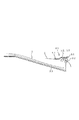
図7は、本実施の形態にかかるシート排出装置の構成を示す図である。なお、図7において、既述した図2と同一符号は、同一または相当部分を示している。 FIG. 7 is a diagram illustrating a configuration of the sheet discharge device according to the present embodiment. In FIG. 7, the same reference numerals as those in FIG. 2 described above indicate the same or corresponding parts.
図7において、64はシート幅方向中央部に配置されている第1検出レバーであり、この第1検出レバー64には、検出手段としての被検出部64dが備えられている。また、65、66はシート幅方向の通紙可能な最大幅の位置にされている第2及び第3検出レバーである。
In FIG. 7,
67は第1検出レバー64と第2検出レバー65の間に配置されている第4検出レバー、68は第1検出レバー64と第3検出レバー66の間に配置されている第5検出レバーである。このように、本実施の形態では、シートSを検出するためのシート検出部材が複数設けられている。つまり、本実施の形態では、中央押さえ部材としても作用する第1検出レバー64の幅方向両側に、側端部押さえ部材としても作用する第2〜第5検出レバー65〜68を2つ(複数)設けている。
67 is a fourth detection lever arranged between the
ここで、図8に示すように第4検出レバー67及び第5検出レバー68がシートSに当接する部分は第1検出レバー64がシートに当接する部分よりも下方向へ突出している。また、第2検出レバー65及び第3検出レバー66がシートSに当接する部分は、第4検出レバー67及び第5検出レバー68がシートに当接する部分よりも下方向へ突出している。つまり、本実施の形態においては、中央から端に向かうに連れて検出レバーが下方向へ突出している。
Here, as shown in FIG. 8, the portion where the
また、第4及び第5検出レバー67,68は第1検出レバー64よりも排出方向上流側に位置し、第2及び第3検出レバー65,66は第4及び第5検出レバー67,68よりも排出方向上流側に位置している。
The fourth and fifth detection levers 67 and 68 are located upstream of the
なお、本実施の形態において、第2及び第3検出レバー65,66は、例えばA4横サイズのシートSの両側端部に臨む位置に設けられ、第4及び第5検出レバー67,68はA5縦サイズのシートSの両側端部に臨む位置に設けられている。 In the present embodiment, the second and third detection levers 65 and 66 are provided, for example, at positions facing both side edges of the A4 landscape sheet S, and the fourth and fifth detection levers 67 and 68 are A5. It is provided at a position facing both end portions of the vertical sheet S.
これにより、例えばA4横サイズのシートSを通紙したとき、排出されるシートにより、第2及び第3検出レバー65,66が押圧されて上方回動する。そして、このように第2及び第3検出レバー65,66が上方回動すると、第2及び第3検出レバー65,66により押圧されて第4及び第5検出レバー67、68が上方回動する。さらに、このように第4及び第5検出レバー67,68が上方回動する回動すると、第4及び第5検出レバー67,68により押圧されて第1検出レバー64が押し上げられて上方回動する。
Thus, for example, when the A4 landscape sheet S is passed, the second and third detection levers 65 and 66 are pressed and rotated upward by the discharged sheet. When the second and third detection levers 65 and 66 are rotated upward in this manner, the fourth and fifth detection levers 67 and 68 are rotated upward by being pressed by the second and third detection levers 65 and 66. . Further, when the fourth and fifth detection levers 67 and 68 are pivoted upward in this manner, the
なお、このように第2及び第3検出レバー65,66、第4及び第5検出レバー67,68を上方回動させながらシートが排出される際、シートSの幅方向端部は、第2〜第5検出レバー65〜68により押し下げられる。これにより、シートSは幅方向において中央部よりも端部が下がって湾曲状態に変形しながら排出される。 Note that when the sheet is discharged while the second and third detection levers 65 and 66 and the fourth and fifth detection levers 67 and 68 are rotated upward in this way, the end in the width direction of the sheet S is the second end. Are pushed down by fifth detection levers 65-68. As a result, the sheet S is discharged while being deformed into a curved state with its end portion lower than the central portion in the width direction.
また、A5縦サイズのシートSを通紙したとき、シートSの先端は最初に第4及び第5検出レバー67,68に接触する。これにより、シートSの幅方向端部は、第4第5検出レバー67,68に押し下げられ、シートSは中央部よりも端部が下がって湾曲状態に変形しながら排出される。 When the A5 vertical size sheet S is passed, the leading edge of the sheet S first comes into contact with the fourth and fifth detection levers 67 and 68. As a result, the end portion in the width direction of the sheet S is pushed down by the fourth and fifth detection levers 67 and 68, and the sheet S is discharged while being deformed into a curved state with the end portion lower than the center portion.
このように、本実施の形態においては、既述した第1の実施の形態で説明したような湾曲を、使用されるシートSのサイズに関わらずシートSに与えることができる。これにより、シートSのサイズに関わらず、シートSの搬送方向のコシを強くすることができ、より安定したシート排出装置を得ることができる。 Thus, in the present embodiment, the curvature as described in the first embodiment can be given to the sheet S regardless of the size of the used sheet S. Thereby, the stiffness in the conveying direction of the sheet S can be increased regardless of the size of the sheet S, and a more stable sheet discharging apparatus can be obtained.
1 カラープリンタ
1B 画像形成部
1D シート排出装置
32 排出ローラ対
33 積載トレイ
50 押さえ部
51 第1検出レバー
51d 被検出部
52 第2検出レバー
53 第3検出レバー
54 光透過型センサ
55 回動中心軸
62 第2検出レバー
63 第3検出レバー
64 第1検出レバー
64d 被検出部
65 第2検出レバー
66 第3検出レバー
67 第4検出レバー
68 第5検出レバー
S シート
DESCRIPTION OF
Claims (8)
前記押さえ部は、
前記シート排出手段により排出されるシートの排出方向と直交する幅方向の中央部を押さえる上下方向に回動自在な中央押さえ部材と、
前記中央押さえ部材の両側で排出されるシートと当接する上下方向に回動自在な側端部押さえ部材と、を備え、
シートを排出する際、排出されるシートの両端部を前記側端部押さえ部材によって前記中央押さえ部材よりも排出方向上流側で押さえることを特徴とするシート排出装置。 In a sheet discharging apparatus comprising: a sheet discharging unit that discharges a sheet to a sheet stacking unit; and a pressing unit that presses the sheet discharged to the sheet stacking unit from above.
The pressing portion is
A central pressing member that is rotatable in the vertical direction and presses the central portion in the width direction orthogonal to the discharging direction of the sheet discharged by the sheet discharging means;
A side end pressing member that is rotatable in the up-down direction contacting the sheet discharged on both sides of the central pressing member,
When discharging a sheet, the sheet discharging apparatus is characterized in that both end portions of the discharged sheet are pressed by the side end pressing member on the upstream side in the discharging direction from the central pressing member.
Priority Applications (1)
| Application Number | Priority Date | Filing Date | Title |
|---|---|---|---|
| JP2008334037A JP2010155681A (en) | 2008-12-26 | 2008-12-26 | Sheet ejecting device and image forming device |
Applications Claiming Priority (1)
| Application Number | Priority Date | Filing Date | Title |
|---|---|---|---|
| JP2008334037A JP2010155681A (en) | 2008-12-26 | 2008-12-26 | Sheet ejecting device and image forming device |
Publications (1)
| Publication Number | Publication Date |
|---|---|
| JP2010155681A true JP2010155681A (en) | 2010-07-15 |
Family
ID=42573906
Family Applications (1)
| Application Number | Title | Priority Date | Filing Date |
|---|---|---|---|
| JP2008334037A Pending JP2010155681A (en) | 2008-12-26 | 2008-12-26 | Sheet ejecting device and image forming device |
Country Status (1)
| Country | Link |
|---|---|
| JP (1) | JP2010155681A (en) |
Cited By (3)
| Publication number | Priority date | Publication date | Assignee | Title |
|---|---|---|---|---|
| US20190071271A1 (en) * | 2017-09-07 | 2019-03-07 | Canon Kabushiki Kaisha | Sheet conveyance apparatus and image forming apparatus |
| US11124378B2 (en) | 2019-07-03 | 2021-09-21 | Canon Kabushiki Kaisha | Sheet discharging apparatus and image forming apparatus |
| US11649129B2 (en) * | 2018-06-27 | 2023-05-16 | Canon Kabushiki Kaisha | Sheet discharge apparatus and image forming apparatus |
-
2008
- 2008-12-26 JP JP2008334037A patent/JP2010155681A/en active Pending
Cited By (4)
| Publication number | Priority date | Publication date | Assignee | Title |
|---|---|---|---|---|
| US20190071271A1 (en) * | 2017-09-07 | 2019-03-07 | Canon Kabushiki Kaisha | Sheet conveyance apparatus and image forming apparatus |
| US10543999B2 (en) * | 2017-09-07 | 2020-01-28 | Canon Kabushiki Kaisha | Sheet conveyance apparatus and image forming apparatus |
| US11649129B2 (en) * | 2018-06-27 | 2023-05-16 | Canon Kabushiki Kaisha | Sheet discharge apparatus and image forming apparatus |
| US11124378B2 (en) | 2019-07-03 | 2021-09-21 | Canon Kabushiki Kaisha | Sheet discharging apparatus and image forming apparatus |
Similar Documents
| Publication | Publication Date | Title |
|---|---|---|
| JP5195121B2 (en) | Recording medium conveying apparatus and image forming apparatus | |
| EP2246281B1 (en) | Sheet conveying apparatus and image forming apparatus | |
| US9229411B2 (en) | Sheet curl correction apparatus and image forming apparatus | |
| US9873576B2 (en) | Sheet feeding apparatus and image forming apparatus | |
| US20090243205A1 (en) | Sheet conveying apparatus and image forming apparatus | |
| US10214373B2 (en) | Sheet feeding device and image forming apparatus | |
| US20170291782A1 (en) | Sheet conveying apparatus and image forming apparatus | |
| US11713204B2 (en) | Sheet conveying apparatus, image reading apparatus, and image forming apparatus | |
| US9533849B2 (en) | Sheet conveyance apparatus and image forming apparatus | |
| JP2009075478A (en) | Image forming apparatus | |
| JP2020075820A (en) | Sheet feeder | |
| US11124378B2 (en) | Sheet discharging apparatus and image forming apparatus | |
| JP2010155681A (en) | Sheet ejecting device and image forming device | |
| JP6929132B2 (en) | Sheet transfer device and image forming device | |
| JP6566795B2 (en) | Sheet feeding apparatus and image forming apparatus | |
| JP7487365B2 (en) | SHEET FEEDING DEVICE, IMAGE READING DEVICE, AND IMAGE FORMING APPARATUS | |
| JP7549796B2 (en) | Feeding device and image forming system | |
| US20240034586A1 (en) | Sheet conveyance apparatus and image forming apparatus | |
| JP7155817B2 (en) | CONVEYING DEVICE, IMAGE FORMING APPARATUS, AND IMAGE FORMING SYSTEM | |
| JP2018111594A (en) | Sheet alignment device, sheet processing device, and image formation device | |
| JP6750874B2 (en) | Sheet feeding apparatus and image forming apparatus | |
| JP6299688B2 (en) | Sheet post-processing apparatus and image forming system including the same | |
| JP2016132546A (en) | Sheet feeding device and image formation apparatus | |
| JP2015212717A (en) | Image forming apparatus | |
| US20170090389A1 (en) | Image forming apparatus |