JP2010134973A - Optical recording medium - Google Patents
Optical recording medium Download PDFInfo
- Publication number
- JP2010134973A JP2010134973A JP2008307233A JP2008307233A JP2010134973A JP 2010134973 A JP2010134973 A JP 2010134973A JP 2008307233 A JP2008307233 A JP 2008307233A JP 2008307233 A JP2008307233 A JP 2008307233A JP 2010134973 A JP2010134973 A JP 2010134973A
- Authority
- JP
- Japan
- Prior art keywords
- recording
- film
- standard
- recording medium
- optical
- Prior art date
- Legal status (The legal status is an assumption and is not a legal conclusion. Google has not performed a legal analysis and makes no representation as to the accuracy of the status listed.)
- Pending
Links
- 230000003287 optical effect Effects 0.000 title claims abstract description 46
- 229910010272 inorganic material Inorganic materials 0.000 claims abstract description 13
- 239000011147 inorganic material Substances 0.000 claims abstract description 13
- 239000012782 phase change material Substances 0.000 claims abstract description 5
- 239000011368 organic material Substances 0.000 claims abstract description 4
- 239000000758 substrate Substances 0.000 claims description 22
- 229910045601 alloy Inorganic materials 0.000 claims description 6
- 239000000956 alloy Substances 0.000 claims description 6
- 238000002844 melting Methods 0.000 claims description 5
- 230000008018 melting Effects 0.000 claims description 5
- 229910052751 metal Inorganic materials 0.000 claims description 5
- 239000002184 metal Substances 0.000 claims description 5
- 150000004767 nitrides Chemical class 0.000 claims description 4
- 239000012860 organic pigment Substances 0.000 abstract 1
- 239000010408 film Substances 0.000 description 84
- 239000000975 dye Substances 0.000 description 27
- 239000000463 material Substances 0.000 description 27
- 238000000034 method Methods 0.000 description 12
- 230000001681 protective effect Effects 0.000 description 9
- 229920005989 resin Polymers 0.000 description 8
- 239000011347 resin Substances 0.000 description 8
- 230000000052 comparative effect Effects 0.000 description 6
- 229910004298 SiO 2 Inorganic materials 0.000 description 5
- 238000005259 measurement Methods 0.000 description 5
- 239000004417 polycarbonate Substances 0.000 description 5
- 229920000515 polycarbonate Polymers 0.000 description 5
- 238000004528 spin coating Methods 0.000 description 5
- 238000002310 reflectometry Methods 0.000 description 4
- 238000004544 sputter deposition Methods 0.000 description 4
- CSUFEOXMCRPQBB-UHFFFAOYSA-N 1,1,2,2-tetrafluoropropan-1-ol Chemical compound CC(F)(F)C(O)(F)F CSUFEOXMCRPQBB-UHFFFAOYSA-N 0.000 description 3
- 229910000763 AgInSbTe Inorganic materials 0.000 description 3
- ANRHNWWPFJCPAZ-UHFFFAOYSA-M thionine Chemical compound [Cl-].C1=CC(N)=CC2=[S+]C3=CC(N)=CC=C3N=C21 ANRHNWWPFJCPAZ-UHFFFAOYSA-M 0.000 description 3
- SVONRAPFKPVNKG-UHFFFAOYSA-N 2-ethoxyethyl acetate Chemical compound CCOCCOC(C)=O SVONRAPFKPVNKG-UHFFFAOYSA-N 0.000 description 2
- 239000004793 Polystyrene Substances 0.000 description 2
- 239000000853 adhesive Substances 0.000 description 2
- 230000001070 adhesive effect Effects 0.000 description 2
- 239000000987 azo dye Substances 0.000 description 2
- 229910052797 bismuth Inorganic materials 0.000 description 2
- 238000006243 chemical reaction Methods 0.000 description 2
- 238000005516 engineering process Methods 0.000 description 2
- 229910052738 indium Inorganic materials 0.000 description 2
- 238000001755 magnetron sputter deposition Methods 0.000 description 2
- 238000004519 manufacturing process Methods 0.000 description 2
- 239000001007 phthalocyanine dye Substances 0.000 description 2
- 229920005668 polycarbonate resin Polymers 0.000 description 2
- 239000004431 polycarbonate resin Substances 0.000 description 2
- 229920002223 polystyrene Polymers 0.000 description 2
- 239000002904 solvent Substances 0.000 description 2
- 238000003860 storage Methods 0.000 description 2
- 229910052718 tin Inorganic materials 0.000 description 2
- 238000002834 transmittance Methods 0.000 description 2
- 229910018072 Al 2 O 3 Inorganic materials 0.000 description 1
- 229910000618 GeSbTe Inorganic materials 0.000 description 1
- 229910004541 SiN Inorganic materials 0.000 description 1
- VYPSYNLAJGMNEJ-UHFFFAOYSA-N Silicium dioxide Chemical compound O=[Si]=O VYPSYNLAJGMNEJ-UHFFFAOYSA-N 0.000 description 1
- CDBYLPFSWZWCQE-UHFFFAOYSA-L Sodium Carbonate Chemical compound [Na+].[Na+].[O-]C([O-])=O CDBYLPFSWZWCQE-UHFFFAOYSA-L 0.000 description 1
- NIXOWILDQLNWCW-UHFFFAOYSA-N acrylic acid group Chemical group C(C=C)(=O)O NIXOWILDQLNWCW-UHFFFAOYSA-N 0.000 description 1
- 125000002723 alicyclic group Chemical group 0.000 description 1
- 229910052782 aluminium Inorganic materials 0.000 description 1
- 239000005354 aluminosilicate glass Substances 0.000 description 1
- 239000005388 borosilicate glass Substances 0.000 description 1
- 239000000919 ceramic Substances 0.000 description 1
- 239000011248 coating agent Substances 0.000 description 1
- 238000000576 coating method Methods 0.000 description 1
- 229910052802 copper Inorganic materials 0.000 description 1
- 239000013078 crystal Substances 0.000 description 1
- 238000001723 curing Methods 0.000 description 1
- 238000000151 deposition Methods 0.000 description 1
- 230000008021 deposition Effects 0.000 description 1
- 230000006866 deterioration Effects 0.000 description 1
- 238000010586 diagram Methods 0.000 description 1
- 238000010894 electron beam technology Methods 0.000 description 1
- 230000007613 environmental effect Effects 0.000 description 1
- 229910052733 gallium Inorganic materials 0.000 description 1
- 229910052732 germanium Inorganic materials 0.000 description 1
- 229910052737 gold Inorganic materials 0.000 description 1
- 238000010438 heat treatment Methods 0.000 description 1
- 238000007733 ion plating Methods 0.000 description 1
- 238000010030 laminating Methods 0.000 description 1
- 229910052745 lead Inorganic materials 0.000 description 1
- 150000002739 metals Chemical class 0.000 description 1
- 238000002156 mixing Methods 0.000 description 1
- 239000000203 mixture Substances 0.000 description 1
- 238000012986 modification Methods 0.000 description 1
- 230000004048 modification Effects 0.000 description 1
- 238000012544 monitoring process Methods 0.000 description 1
- 238000000465 moulding Methods 0.000 description 1
- 229910052759 nickel Inorganic materials 0.000 description 1
- 239000003208 petroleum Substances 0.000 description 1
- 238000000016 photochemical curing Methods 0.000 description 1
- 229920003229 poly(methyl methacrylate) Polymers 0.000 description 1
- 239000004926 polymethyl methacrylate Substances 0.000 description 1
- 229920000306 polymethylpentene Polymers 0.000 description 1
- 239000011116 polymethylpentene Substances 0.000 description 1
- 229920000098 polyolefin Polymers 0.000 description 1
- 229920005672 polyolefin resin Polymers 0.000 description 1
- 239000004800 polyvinyl chloride Substances 0.000 description 1
- 229920000915 polyvinyl chloride Polymers 0.000 description 1
- 230000005855 radiation Effects 0.000 description 1
- 238000005546 reactive sputtering Methods 0.000 description 1
- 229910052710 silicon Inorganic materials 0.000 description 1
- 229910052709 silver Inorganic materials 0.000 description 1
- 239000005361 soda-lime glass Substances 0.000 description 1
- 229920005992 thermoplastic resin Polymers 0.000 description 1
- 239000010409 thin film Substances 0.000 description 1
- 239000012780 transparent material Substances 0.000 description 1
- 238000001771 vacuum deposition Methods 0.000 description 1
- 229910052725 zinc Inorganic materials 0.000 description 1
Images

Landscapes
- Thermal Transfer Or Thermal Recording In General (AREA)
- Optical Record Carriers And Manufacture Thereof (AREA)
Abstract
Description
本発明は、レーザ光の照射によって情報の記録、消去、再生を行う光記録媒体に関するものである。特に本発明は、記録膜に有機色素膜を用いた追記型の光記録媒体に関する。 The present invention relates to an optical recording medium that records, erases, and reproduces information by irradiation with a laser beam. In particular, the present invention relates to a write-once type optical recording medium using an organic dye film as a recording film.
現在、CD(コンパクトディスク)、DVD(デジタルヴァーサタイルディスク)に代表される光記録媒体は記憶容量、ランダムアクセス性、可搬性、価格等の理由から広く普及している。また、青色レーザを用いたBD(ブルーレイディスク)も普及し始めている。光記録媒体には再生専用型、書き換え可能型、1回だけ記録が可能な追記型がある。その中でも追記型はCD−R、DVD−R等と呼ばれ、その価格の安さから普及が拡大している。 At present, optical recording media represented by CD (compact disc) and DVD (digital versatile disc) are widely used for reasons such as storage capacity, random accessibility, portability, and price. Also, BD (Blu-ray Disc) using a blue laser has begun to spread. Optical recording media include a read-only type, a rewritable type, and a write-once type that can be recorded only once. Among them, the write-once type is called CD-R, DVD-R, etc., and its spread is expanding due to its low price.
一般に追記型のCD、DVDの記録膜にはレーザ光を吸収して物理的変化や化学反応をおこす有機色素記録膜が用いられる。一方、青色レーザを用いて記録するBDにおいては高速記録の容易さから無機記録膜を用いる追記型ディスクが先行して開発されている。しかしながら、CD、DVDからの技術の流用、コストメリット等を考慮して有機色素記録膜を用いた追記型BDの検討も行われている。有機色素記録膜を用いた追記型BDについて、例えば特開2003−59108号公報(特許文献1)に記載のものがある。 Generally, an organic dye recording film that absorbs a laser beam and causes a physical change or chemical reaction is used for a recording film of a write-once CD or DVD. On the other hand, write-once discs using an inorganic recording film have been developed in advance for BD recording using a blue laser because of the ease of high-speed recording. However, the write-once BD using an organic dye recording film has been studied in consideration of the diversion of technology from CD and DVD, cost merit, and the like. For example, JP-A-2003-59108 (Patent Document 1) discloses a write-once BD using an organic dye recording film.
有機色素記録膜を用いた追記型BDは、一般に、溝が形成された基板上に反射膜、記録膜、カバー層の順に形成され、カバー層側から記録再生用のレーザを入射する構成となる。また、レーザ入射面から遠い側の溝部に記録マークを形成し、記録マークの反射率が未記録部の反射率より高くなるような構成とすると、望ましい記録再生特性が得られる。このような記録方式は一般にLTH(Low to High)記録と呼ばれている。このような追記型BDについては例えば特開2007−26541号公報(特許文献2)に記載のものがある。
前述したようにCD、DVDからの技術の流用、コストメリット等の面で有利なため、有機色素記録膜を用いた追記型BDの検討が行われている。しかし、有機色素記録膜を用いた追記型BDは、高速記録をした時に、良好な記録再生特性を得ることが難しいという問題点がある。 As described above, since it is advantageous in terms of diverting technology from CD and DVD and cost merit, write-once BD using an organic dye recording film has been studied. However, the write-once BD using an organic dye recording film has a problem that it is difficult to obtain good recording / reproducing characteristics when high-speed recording is performed.
本発明はこのような問題点に鑑みなされたものであり、青色レーザで有機色素記録膜に記録する際に、良好な記録再生特性を得られる光記録媒体を提供することを目的とする。 The present invention has been made in view of such problems, and an object of the present invention is to provide an optical recording medium capable of obtaining good recording / reproducing characteristics when recording on an organic dye recording film with a blue laser.
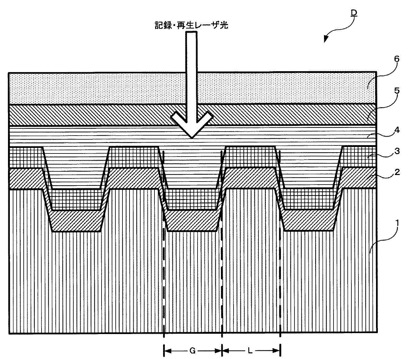
本発明は上述した従来技術の問題点を解決するため、グルーブを有する基板(1)と、基板(1)のグルーブが形成された面上に形成され、入射する記録光を反射する反射膜(2)と、反射膜(2)上に、記録光により光学特性が変化する無機材料を用いて形成された下地膜(3)と、下地膜(3)上に、光によって情報が記録される有機材料を用いて形成された記録膜(4)とを備えることを特徴とする光記録媒体(D)を提供する。 In order to solve the above-mentioned problems of the prior art, the present invention provides a substrate (1) having a groove and a reflective film (1) formed on the surface of the substrate (1) on which the groove is formed and reflecting incident recording light ( 2), a base film (3) formed using an inorganic material whose optical characteristics are changed by recording light on the reflective film (2), and information is recorded on the base film (3) by light. There is provided an optical recording medium (D) comprising a recording film (4) formed using an organic material.
本発明の光記録媒体によれば、青色レーザで有機色素記録膜に記録する際に、良好な記録再生特性を得ることができる。 According to the optical recording medium of the present invention, good recording / reproducing characteristics can be obtained when recording on an organic dye recording film with a blue laser.
以下、本発明の光記録媒体について、添付図面を参照して説明する。図1は本発明の光記録媒体の構成の一実施形態を示す図である。 The optical recording medium of the present invention will be described below with reference to the accompanying drawings. FIG. 1 is a diagram showing an embodiment of the configuration of an optical recording medium of the present invention.
<光記録媒体の構成>
図1を用いて本実施形態における光記録媒体について説明する。光記録媒体Dは、溝を有する基板1上に反射膜2、下地膜3、有機色素記録膜4、透明保護膜5、カバー層6を順次積層した構成となっている。
<Configuration of optical recording medium>
The optical recording medium in this embodiment will be described with reference to FIG. The optical recording medium D has a configuration in which a reflective film 2, a base film 3, an organic dye recording film 4, a transparent protective film 5, and a cover layer 6 are sequentially laminated on a substrate 1 having a groove.
基板1の材料として例えば、ポリカーボネート、ポリメチルメタクリレート、ポリスチレン、ポリカーボネート・ポリスチレン共重合体、ポリビニルクロライド、脂環式ポリオレフィン、ポリメチルペンテンなどの各種熱可塑性樹脂、各種放射線硬化樹脂、紫外線硬化樹脂、可視光硬化樹脂が挙げられる。また、基板材料1の材料として、例えばソーダライムガラス、ソーダアルミノ珪酸ガラス、ホウ珪酸ガラス、石英ガラスなどのセラミックも挙げられる。特に、光学的複屈折、吸湿性の小ささ、成型の容易さ等の理由からポリカーボネート樹脂が好ましい。 Examples of the material of the substrate 1 include polycarbonate, polymethyl methacrylate, polystyrene, polycarbonate / polystyrene copolymer, polyvinyl chloride, alicyclic polyolefin, polymethylpentene, and other various thermoplastic resins, various radiation curable resins, ultraviolet curable resins, visible A photocuring resin is mentioned. Examples of the material of the substrate material 1 include ceramics such as soda lime glass, soda aluminosilicate glass, borosilicate glass, and quartz glass. In particular, polycarbonate resin is preferred for reasons such as optical birefringence, low hygroscopicity, and ease of molding.
基板1の厚みは0.5mm以上1.5mm以下が好ましく、特に0.9mm以上1.3mm以下であることが好ましい。基板1にはグルーブとランドが形成されており、設けられたグルーブの深さは20nm以上100nm以下が好ましく、特に、30nm以上60nm以下であることが好ましい。また、グルーブ幅Gとランド幅Lの比は、50:50から60:40の範囲であることが好ましい。ここで、グルーブは、基板1において、レーザ光の入射方向に対して凹部とする。 The thickness of the substrate 1 is preferably 0.5 mm or more and 1.5 mm or less, and particularly preferably 0.9 mm or more and 1.3 mm or less. Grooves and lands are formed on the substrate 1, and the depth of the provided grooves is preferably 20 nm or more and 100 nm or less, and particularly preferably 30 nm or more and 60 nm or less. The ratio of the groove width G to the land width L is preferably in the range of 50:50 to 60:40. Here, the groove is a recess in the substrate 1 with respect to the incident direction of the laser beam.
反射膜2は、光記録媒体Dに記録をする際に使用する波長405nmのレーザにおいて80%以上の反射率を得られる材料であることが好ましく、90%以上の反射率を得られる材料であれば更に好ましい。そのような理由から、反射膜2の材料として例えば、Ag、Au、及びこれらの金属に1種または複数の元素を添加した合金が挙げられる。中でも環境特性、コストを考慮して、AgにPb、Cu、Ni、Zn、Al、Ga、In、Si、Ge、Sn、Biから選ばれる1種または複数の元素を添加した合金が好ましい。
反射膜2は光記録媒体Dの光学特性と熱特性の制御をする役割がある。反射膜2の膜厚は採用した材料ごとに反射率と記録特性双方が適切な状態となるように設定する必要がある。例えばAgNiCu合金を用いた場合、反射膜2の膜厚は30nm以上100nm以下が好ましい。
The reflective film 2 is preferably a material capable of obtaining a reflectivity of 80% or more in a laser having a wavelength of 405 nm used for recording on the optical recording medium D, and may be a material capable of obtaining a reflectivity of 90% or more. More preferred. For such reasons, examples of the material of the reflective film 2 include Ag, Au, and alloys obtained by adding one or more elements to these metals. Among these, in consideration of environmental characteristics and cost, an alloy in which one or more elements selected from Pb, Cu, Ni, Zn, Al, Ga, In, Si, Ge, Sn, and Bi are added to Ag is preferable.
The reflective film 2 has a role of controlling optical characteristics and thermal characteristics of the optical recording medium D. The film thickness of the reflective film 2 needs to be set so that both reflectivity and recording characteristics are appropriate for each material employed. For example, when an AgNiCu alloy is used, the thickness of the reflective film 2 is preferably 30 nm or more and 100 nm or less.
下地膜3の材料として例えば、BD規格を満足する仕様のレーザを用い、BD規格内の記録パワーでレーザ光を照射した時に、反射率等の光学特性が変化する無機材料であるGeSbTe、AgInSbTe、CuAlTeSbなどの公知の相変化材料を用いることができる。また、高温高湿条件、光照射等の厳しい保存条件においても記録再生特性を維持するために、下地膜3の材料として、上記の材料にTi、In等を添加した材料を用いても良い。
また、下地膜3の材料にはBi、Sn、Te等の融点が600℃以下の金属の酸化物や窒化物、及び、融点が600℃以下の金属を含む合金の酸化物や窒化物を用いても良い。これらの材料も、BD規格を満足する仕様のレーザを用い、BD規格内の記録パワーでレーザ光を照射した時に、光学特性が変化する無機材料である。このような材料として、例えば、GeBiN、BiFeO、Te−O−Pdなどが挙げられる。
For example, GeSbTe, AgInSbTe, which are inorganic materials whose optical characteristics such as reflectance change when a laser beam having a specification satisfying the BD standard is used and the laser beam is irradiated with a recording power within the BD standard, are used as the material of the base film 3. A known phase change material such as CuAlTeSb can be used. Further, in order to maintain the recording / reproducing characteristics even under severe storage conditions such as high temperature and high humidity and light irradiation, a material obtained by adding Ti, In or the like to the above material may be used as the material of the base film 3.
Further, as the material of the base film 3, an oxide or nitride of a metal having a melting point of 600 ° C. or less, such as Bi, Sn, or Te, and an oxide or nitride of an alloy containing a metal having a melting point of 600 ° C. or less are used. May be. These materials are also inorganic materials whose optical characteristics change when a laser having a specification satisfying the BD standard is used and laser light is irradiated with a recording power within the BD standard. Examples of such a material include GeBiN, BiFeO, Te—O—Pd, and the like.
有機色素記録膜4の材料は、記録再生に使用するレーザ光の波長に感光性がある必要がある。さらに、有機色素記録膜4の材料はレーザ光の照射により物理的変化あるいは化学反応することにより屈折率が変化する必要がある。そのような理由から、有機色素記録膜4の材料として例えば、シアニン色素、オキソノール色素、アゾ色素、フタロシアニン色素が挙げられる。これらの有機材料を例えばセロソルブアセテート、テトラフルオロプロパノール等の溶剤と混合した溶液を用い、スピンコート法などにより有機色素記録膜4を形成する。有機色素記録膜4の膜厚は15nm以上25nm以下が好ましい。 The material of the organic dye recording film 4 needs to be sensitive to the wavelength of the laser beam used for recording and reproduction. Further, the refractive index of the material of the organic dye recording film 4 needs to be changed by a physical change or a chemical reaction caused by laser light irradiation. For these reasons, examples of the material for the organic dye recording film 4 include cyanine dyes, oxonol dyes, azo dyes, and phthalocyanine dyes. The organic dye recording film 4 is formed by spin coating or the like using a solution obtained by mixing these organic materials with a solvent such as cellosolve acetate or tetrafluoropropanol. The film thickness of the organic dye recording film 4 is preferably 15 nm or more and 25 nm or less.
透明保護膜5の材料は使用するレーザの波長における透過率が80%以上ある材料が好ましく、透過率が90%以上あれば更に好ましい。透明保護膜5の材料として例えばZnS−SiO2、SiO2、Al2O3、SiNなどの無機系の透明材料が挙げられる。他にも透明保護膜5の材料として例えばポリオレフィン系樹脂、石油樹脂などの透明樹脂が挙げられる。 The material of the transparent protective film 5 is preferably a material having a transmittance of 80% or more at the wavelength of the laser to be used, and more preferably a transmittance of 90% or more. Examples of the material of the transparent protective film 5 include inorganic transparent materials such as ZnS—SiO 2 , SiO 2 , Al 2 O 3 , and SiN. Other examples of the material for the transparent protective film 5 include transparent resins such as polyolefin resins and petroleum resins.
カバー層6の材料としては接着剤が塗布されたポリカーボネートのシートや紫外線硬化樹脂などが挙げられる。 Examples of the material of the cover layer 6 include a polycarbonate sheet coated with an adhesive and an ultraviolet curable resin.
<光記録媒体の製造方法>
次に、本実施形態の光記録媒体Dの製造方法について述べる。
反射膜2、下地膜3、透明保護膜5を基板1上に積層する方法としては、公知の真空中での薄膜形成法が挙げられる。例えば、真空蒸着法(抵抗加熱型や電子ビーム型)、イオンプレーティング法、スパッタリング法(直流や交流スパッタリング、反応性スパッタリング)であり、特に、組成、膜厚のコントロールが容易であることから、スパッタリング法が好ましい。
<Method for producing optical recording medium>
Next, a method for manufacturing the optical recording medium D of this embodiment will be described.
As a method of laminating the reflective film 2, the base film 3, and the transparent protective film 5 on the substrate 1, a known thin film forming method in a vacuum can be cited. For example, vacuum deposition method (resistance heating type or electron beam type), ion plating method, sputtering method (direct current or alternating current sputtering, reactive sputtering), especially because the composition and film thickness can be easily controlled, A sputtering method is preferred.
また、真空漕内で複数の基板1を同時に成膜するバッチ法や、基板1を1枚ずつ処理する枚葉式成膜装置を使用しても良い。形成する反射膜2、下地膜3、透明保護膜5の膜厚の制御は、スパッタ電源の投入パワーと時間を制御したり、水晶振動型膜厚計で堆積状態をモニタリングしたりすることで容易に行える。 Alternatively, a batch method in which a plurality of substrates 1 are simultaneously formed in a vacuum chamber, or a single-wafer type film forming apparatus that processes the substrates 1 one by one may be used. Control of the film thickness of the reflection film 2, the base film 3, and the transparent protective film 5 to be formed is easy by controlling the input power and time of the sputtering power source, or monitoring the deposition state with a crystal vibration type film thickness meter. It can be done.
また、反射膜2、下地膜3、透明保護膜5の形成は、基板1を固定したまま、或いは移動、回転した状態のどちらでも良い。膜厚の面内の均一性に優れることから、基板1を自転させることが好ましく、さらに公転を組み合わせることがより好ましい。必要に応じて基板1の冷却を行うと、基板1の反り量を減少させることができる。
有機色素記録膜4は、例えば、シアニン色素、オキソノール色素、アゾ色素、フタロシアニン色素等の材料を、セロソルブアセテート、テトラフルオロプロパノール等の溶剤と混合した溶液を用いて溶解し、スピンコート法などにより形成する。有機色素記録膜4の膜厚の制御は、スピンコート時のディスクの回転速度や回転時間、色素材料を溶解した溶液の塗布量などを制御することで容易に行える。
In addition, the reflective film 2, the base film 3, and the transparent protective film 5 may be formed while the substrate 1 is fixed, or may be moved or rotated. Since the in-plane uniformity of the film thickness is excellent, the substrate 1 is preferably rotated, and more preferably combined with revolution. When the substrate 1 is cooled as necessary, the amount of warpage of the substrate 1 can be reduced.
The organic dye recording film 4 is formed, for example, by dissolving a material such as cyanine dye, oxonol dye, azo dye, phthalocyanine dye with a solvent such as cellosolve acetate, tetrafluoropropanol, and the like by spin coating or the like. To do. The film thickness of the organic dye recording film 4 can be easily controlled by controlling the rotation speed and rotation time of the disk during spin coating, the coating amount of the solution in which the dye material is dissolved, and the like.
また、カバー層6は、例えば、ポリカーボネートのシートを接着する方法、紫外線硬化樹脂をスピンコート法により塗布し、その後、紫外線照射により硬化させる方法などで形成する。 The cover layer 6 is formed by, for example, a method of adhering a polycarbonate sheet, a method of applying an ultraviolet curable resin by a spin coating method, and then curing by ultraviolet irradiation, or the like.
次に本実施形態に係る光記録媒体Dの実施例1〜実施例4、及び、比較例1〜比較例2について順次説明する。以下の実施例及び比較例では、波長が405±5nmのレーザダイオード、NA=0.85の光学レンズを搭載したパルステック社製光ディスクドライブテスタ(ODU−1000)を用いて所定の情報を記録し、ジッタ及び変調度を評価した。記録はBD規格1倍速(線速度4.92m/s)とBD規格2倍速(線速度9.84m/s)で行った。また、BD規格1倍速での記録パワーは、BD規格により3mW〜6mWと定められている。BD規格2倍速での記録パワーは、BD規格により3mW〜7mWと定められている。それぞれのサンプルにおいて、BD規格内で最適な記録レーザパワーを導き、その記録レーザパワーで記録を行った。 Next, Examples 1 to 4 and Comparative Examples 1 to 2 of the optical recording medium D according to this embodiment will be sequentially described. In the following examples and comparative examples, predetermined information is recorded using an optical disc drive tester (ODU-1000) manufactured by Pulse Tech Co., Ltd. equipped with a laser diode having a wavelength of 405 ± 5 nm and an optical lens having NA = 0.85. Jitter and modulation degree were evaluated. Recording was performed at BD standard 1 × speed (linear velocity 4.92 m / s) and BD standard 2 × speed (linear velocity 9.84 m / s). Further, the recording power at the BD standard 1 × speed is defined as 3 mW to 6 mW by the BD standard. The recording power at the BD standard double speed is defined as 3 mW to 7 mW by the BD standard. In each sample, an optimum recording laser power was derived within the BD standard, and recording was performed with the recording laser power.
(実施例1)
光記録媒体Dは、直径120mmのポリカーボネート樹脂の基板1上に各膜を形成し、作製した。基板1にはトラックピッチが0.32μmでグルーブ、ランドが交互に形成されている。グルーブの深さは37nmであり、グルーブ幅Gとランド幅Lの比は、およそ50:50である。
Example 1
The optical recording medium D was produced by forming each film on a polycarbonate resin substrate 1 having a diameter of 120 mm. Grooves and lands are alternately formed on the substrate 1 with a track pitch of 0.32 μm. The depth of the groove is 37 nm, and the ratio of the groove width G to the land width L is approximately 50:50.
まず、直流マグネトロンスパッタ法により、基板1の溝を有する面に、反射膜2をAgNiCu合金で膜厚40nm、下地膜3をAgInSbTeで膜厚3nmとして順次積層した。AgInSbTeは相変化材料である。
続いて、スピンコート法により、シアニン色素をテトラフルオロプロパノールに0.5wt%の濃度で溶解した溶液を用いて、膜厚18nmの有機色素記録膜4を形成した。
続いて、直流マグネトロンスパッタ法により、透明保護膜5をZnS−SiO2で膜厚20nmとして形成した。その後、アクリル系の紫外線硬化樹脂を接着剤として用いて、ポリカーボネートからなる厚さ0.1mmのシートをカバー層6として、透明保護膜5の上に貼り付けて光記録媒体Dを作製した。
First, the direct current magnetron sputtering method was used to sequentially laminate the reflective film 2 with an AgNiCu alloy with a film thickness of 40 nm and the base film 3 with AgInSbTe with a film thickness of 3 nm on the surface having the groove. AgInSbTe is a phase change material.
Subsequently, an organic dye recording film 4 having a film thickness of 18 nm was formed by a spin coating method using a solution in which a cyanine dye was dissolved in tetrafluoropropanol at a concentration of 0.5 wt%.
Subsequently, the transparent protective film 5 was formed to a thickness of 20 nm with ZnS—SiO 2 by direct current magnetron sputtering. Thereafter, an optical recording medium D was prepared by attaching a 0.1 mm-thick polycarbonate sheet as a cover layer 6 on the transparent protective film 5 using an acrylic ultraviolet curable resin as an adhesive.
こうして製造した光記録媒体Dを用い、有機色素記録膜4の、基盤1のグルーブ上に形成された部分に記録した。この部分は、図1の記録・再生レーザ光の入射方向から見て凹状になっている部分である。
BD規格1倍速(線速度4.92m/s)の条件で所定の情報を記録し、ジッタ値、変調度を測定したところ、ジッタ値6.41%、変調度38.7%であった。表1にこの結果を示す。さらに、BD規格2倍速(線速度9.84m/s)の条件で所定の情報を記録し、ジッタ値、変調度を測定したところ、表1に示すとおり、ジッタ値7.72%、変調度42.1%であった。本実施形態ではBD規格1倍速記録でのジッタが7%以下かつBD規格2倍速記録でのジッタが8%以下の場合、良好な記録特性が得られたとする。この条件を満たした場合は、表中に「OK」を、満たさない場合は「NG」を記す。従って、本実施例の光記録媒体Dは、BD規格1倍速の記録だけでなく、BD規格2倍速の高速記録でも良好な特性が得られた。
Using the optical recording medium D thus manufactured, recording was performed on a portion of the organic dye recording film 4 formed on the groove of the substrate 1. This portion is a concave portion when viewed from the incident direction of the recording / reproducing laser beam in FIG.
When predetermined information was recorded under the condition of BD standard 1 × speed (linear velocity 4.92 m / s) and the jitter value and modulation factor were measured, the jitter value was 6.41% and the modulation factor was 38.7%. Table 1 shows the results. Furthermore, when predetermined information was recorded under the condition of BD standard double speed (linear velocity 9.84 m / s) and the jitter value and the modulation degree were measured, as shown in Table 1, the jitter value was 7.72%, the modulation degree. It was 42.1%. In the present embodiment, it is assumed that good recording characteristics are obtained when the jitter in the BD standard 1x recording is 7% or less and the jitter in the BD standard 2x recording is 8% or less. When this condition is satisfied, “OK” is described in the table, and when the condition is not satisfied, “NG” is described. Therefore, the optical recording medium D of this example has good characteristics not only for BD standard 1 × speed recording but also for BD standard 2 × high speed recording.
(実施例2)
下地膜3の膜厚の材料をGeBiNとした他は、実施例1と同様の光記録媒体Dを作製した。GeBiNは相変化材料ではないがレーザ光の照射によって光学的特性が変化する無機材料である。また、下地膜3の膜厚についても実施例1と同様に3nmとした。
実施例1と同様の記録及び測定をしたところ、表1に示すとおり、BD規格1倍速の記録でジッタ値6.41%、変調度38.3%であり、BD規格2倍速の記録でジッタ値7.86%、変調度42.2%であった。従って、いずれの規格速度で記録した場合もジッタの条件を満足した。
(Example 2)
An optical recording medium D was produced in the same manner as in Example 1 except that the material of the base film 3 was GeBiN. GeBiN is not a phase change material, but is an inorganic material whose optical properties change upon irradiation with laser light. Further, the film thickness of the base film 3 was also set to 3 nm as in Example 1.
When recording and measurement were performed in the same manner as in Example 1, as shown in Table 1, the jitter value was 6.41% and the modulation factor was 38.3% in the BD standard 1x recording, and the jitter in the BD standard 2x recording. The value was 7.86% and the modulation degree was 42.2%. Therefore, the jitter condition was satisfied when recording was performed at any standard speed.
(実施例3)
下地膜3の膜厚を2nmとした他は、実施例1と同様の光記録媒体Dを作製した。実施例1と同様の記録及び測定をしたところ、表1に示すとおり、BD規格1倍速の記録でジッタ値6.38%、変調度38.0%であり、BD規格2倍速の記録でジッタ値7.98%、変調度41.1%であった。従って、いずれの規格速度で記録した場合もジッタの条件を満足した。
(Example 3)
An optical recording medium D similar to that of Example 1 was manufactured except that the thickness of the base film 3 was set to 2 nm. When recording and measurement were performed in the same manner as in Example 1, as shown in Table 1, the jitter value was 6.38% and the modulation factor was 38.0% in BD standard 1x recording, and jitter was recorded in BD standard 2x recording. The value was 7.98% and the modulation degree was 41.1%. Therefore, the jitter condition was satisfied when recording was performed at any standard speed.
(実施例4)
下地膜3の膜厚を5nmとした他は、実施例1と同様の光記録媒体Dを作製した。実施例1と同様の記録及び測定をしたところ、表1に示すとおり、BD規格1倍速の記録でジッタ値6.55%、変調度41.1%であり、BD規格2倍速の記録でジッタ値7.80%、変調度42.0%であった。従って、いずれの規格速度で記録した場合もジッタの条件を満足した。
Example 4
An optical recording medium D similar to that of Example 1 was manufactured except that the thickness of the base film 3 was changed to 5 nm. When recording and measurement were performed in the same manner as in Example 1, as shown in Table 1, the jitter value was 6.55% and the modulation factor was 41.1% in the BD standard 1x recording, and the jitter in the BD standard 2x recording. The value was 7.80% and the modulation degree was 42.0%. Therefore, the jitter condition was satisfied when recording was performed at any standard speed.
(比較例1)
下地膜3を設けない以外は、実施例1と同様の光記録媒体Dを作製した。実施例1と同様の記録及び測定をしたところ、表1に示すとおり、BD規格1倍速の記録でジッタ値6.35%、変調度38.5%であり、BD規格2倍速の記録でジッタ値8.53%、変調度40.6%であった。BD規格1倍速の記録では7%以下のジッタが得られたものの、BD規格2倍速ではジッタが著しく悪化した。
(Comparative Example 1)
An optical recording medium D similar to that of Example 1 was prepared except that the base film 3 was not provided. When recording and measurement were performed in the same manner as in Example 1, as shown in Table 1, the jitter value was 6.35% and the modulation factor was 38.5% in BD standard 1x recording, and jitter was recorded in BD standard 2x recording. The value was 8.53% and the degree of modulation was 40.6%. Although a jitter of 7% or less was obtained in the BD standard 1 × speed recording, the jitter was remarkably deteriorated in the BD standard 2 × speed.
(比較例2)
下地膜3の材料をZnS−SiO2とした他は、実施例1と同様の光記録媒体Dを作製した。ZnS−SiO2は、レーザ光の照射によっても光学特性が変化しない無機材料である。実施例1と同様の記録及び測定をしたところ、表1に示すとおり、BD規格1倍速の記録でジッタ値7.35%、変調度32.9%であり、BD規格2倍速の記録でジッタ値8.78%、変調度36.1%であった。BD規格1倍速及びBD規格2倍速のジッタが著しく悪化した。
(Comparative Example 2)
An optical recording medium D was produced in the same manner as in Example 1 except that the material of the base film 3 was changed to ZnS—SiO 2 . ZnS—SiO 2 is an inorganic material whose optical properties do not change even when irradiated with laser light. When recording and measurement were performed in the same manner as in Example 1, as shown in Table 1, the jitter value was 7.35% and the modulation factor was 32.9% in BD standard 1x recording, and jitter was recorded in BD standard 2x recording. The value was 8.78% and the modulation degree was 36.1%. Jitter of BD standard 1 × speed and BD standard 2 × speed was remarkably deteriorated.
下地膜2にレーザ光の照射により光学特性が変化する無機材料を用いた実施例1〜4は、BD規格1倍速記録でジッタ7%以下、BD規格2倍速記録でジッタ8%以下を満足し、高速記録でも良好な記録特性が得られた。一方で比較例1,2は、実施例に比べてジッタが悪化した。
このような結果から、比較例1,2のジッタが悪化した原因は、下地膜2を設けていなかったこと、または、下地膜2の材料が、BD規格を満足する仕様のレーザを用いて、BD規格内の記録パワーでレーザ光を照射しても光学特性が変化しない材料であったことが原因だとわかる。
Examples 1 to 4 using an inorganic material whose optical characteristics change when irradiated with laser light for the base film 2 satisfy a jitter of 7% or less for BD standard 1x recording and a jitter of 8% or less for BD standard 2x recording. Good recording characteristics were obtained even at high speed recording. On the other hand, the jitter in Comparative Examples 1 and 2 was worse than that in the Example.
From such a result, the cause of the deterioration of the jitters of Comparative Examples 1 and 2 was that the base film 2 was not provided, or the material of the base film 2 was a laser having a specification satisfying the BD standard. It can be understood that the reason is that the optical characteristics did not change even when the laser beam was irradiated with the recording power within the BD standard.
実施例1〜4のように、下地膜3にBD規格を満足する仕様のレーザを用い、BD規格内の記録パワーでレーザ光を照射した時に、光学特性が変化する無機材料を用いた場合は、記録後に下地膜3の反射率が向上することがジッタ良化の要因だと考えられる。また、このような無機材料は一般に融点が600℃以下と低いため、レーザ光の照射により柔軟になり、有機色素記録膜4の形状変化を起こしやすくしていることもジッタ良化の要因と考えられる。 When using an inorganic material whose optical characteristics change when a laser beam with a specification satisfying the BD standard is used for the base film 3 and laser light is irradiated with a recording power within the BD standard, as in Examples 1 to 4. It can be considered that the improvement in the reflectivity of the underlying film 3 after recording is a factor in improving the jitter. In addition, since such an inorganic material generally has a melting point as low as 600 ° C. or less, it is considered to be a factor in improving jitter that it becomes flexible by irradiation with laser light and easily changes in shape of the organic dye recording film 4. It is done.
本発明は以上説明した各実施形態に限定されることはなく、本発明の要旨を逸脱しない範囲において種々変更が可能である。 The present invention is not limited to the embodiments described above, and various modifications can be made without departing from the spirit of the present invention.
1 基板
2 反射膜
3 下地膜
4 有機色素記録膜
1 Substrate 2 Reflecting film 3 Base film 4 Organic dye recording film
Claims (3)
前記基板の前記グルーブが形成された面上に形成され、入射する記録光を反射する反射膜と、
前記反射膜上に、前記記録光により光学特性が変化する無機材料を用いて形成された下地膜と、
前記下地膜上に、前記記録光によって情報が記録される有機材料を用いて形成された記録膜と
を備えることを特徴とする光記録媒体。 A substrate having a groove;
A reflective film that is formed on a surface of the substrate on which the groove is formed and reflects incident recording light;
On the reflective film, a base film formed using an inorganic material whose optical characteristics are changed by the recording light; and
An optical recording medium comprising: a recording film formed using an organic material on which information is recorded by the recording light on the base film.
Priority Applications (1)
| Application Number | Priority Date | Filing Date | Title |
|---|---|---|---|
| JP2008307233A JP2010134973A (en) | 2008-12-02 | 2008-12-02 | Optical recording medium |
Applications Claiming Priority (1)
| Application Number | Priority Date | Filing Date | Title |
|---|---|---|---|
| JP2008307233A JP2010134973A (en) | 2008-12-02 | 2008-12-02 | Optical recording medium |
Publications (1)
| Publication Number | Publication Date |
|---|---|
| JP2010134973A true JP2010134973A (en) | 2010-06-17 |
Family
ID=42346124
Family Applications (1)
| Application Number | Title | Priority Date | Filing Date |
|---|---|---|---|
| JP2008307233A Pending JP2010134973A (en) | 2008-12-02 | 2008-12-02 | Optical recording medium |
Country Status (1)
| Country | Link |
|---|---|
| JP (1) | JP2010134973A (en) |
-
2008
- 2008-12-02 JP JP2008307233A patent/JP2010134973A/en active Pending
Similar Documents
| Publication | Publication Date | Title |
|---|---|---|
| JP5560261B2 (en) | Information recording medium | |
| US6469977B2 (en) | Optical information recording medium, method for producing the same, and method and apparatus for recording/reproducing information thereon | |
| JP5151418B2 (en) | Write-once optical recording medium and manufacturing method thereof | |
| JP2000322770A (en) | Optical information recording medium | |
| KR20040014917A (en) | Optical recording medium and method for optically recording data in the same | |
| WO2010073971A1 (en) | Dye for optical information recording medium and optical information recording medium | |
| JPH11250502A (en) | optical disk | |
| JP2003276342A (en) | Optical recording medium | |
| TWI427630B (en) | Optical information recording media with color and optical information recording media | |
| JPH10340489A (en) | Phase transition type optical disk and production of phase transition type optical disk | |
| JP5298623B2 (en) | Write-once optical recording medium | |
| US7875365B2 (en) | Recordable optical recording media | |
| JP2010134973A (en) | Optical recording medium | |
| KR20050059098A (en) | Rewritable optical data storage medium and use of such a medium | |
| US20080084812A1 (en) | Multilayer phase-change optical storage medium | |
| JP4322719B2 (en) | Optical information recording medium, method for producing the same, and sputtering target | |
| JP2002230839A (en) | Optical recording medium | |
| WO2010032348A1 (en) | Information recording medium and process for producing the same | |
| JP2005302264A (en) | Phase change optical information recording medium and two-layer phase change optical information recording medium | |
| KR20050026477A (en) | Multi-stack optical data storage medium and use of such medium | |
| JP4232159B2 (en) | Optical recording medium | |
| JP4093926B2 (en) | Optical recording medium | |
| KR20040108770A (en) | Multi-stack optical data storage medium and use of such medium | |
| US20060165946A1 (en) | Optical storage medium | |
| JP5205521B2 (en) | Dye for optical information recording medium and optical information recording medium using the same |