JP2010119794A - Structure of corner cabinet and method of assembling the same - Google Patents
Structure of corner cabinet and method of assembling the same Download PDFInfo
- Publication number
- JP2010119794A JP2010119794A JP2008298701A JP2008298701A JP2010119794A JP 2010119794 A JP2010119794 A JP 2010119794A JP 2008298701 A JP2008298701 A JP 2008298701A JP 2008298701 A JP2008298701 A JP 2008298701A JP 2010119794 A JP2010119794 A JP 2010119794A
- Authority
- JP
- Japan
- Prior art keywords
- storage box
- rectangular parallelepiped
- parallelepiped storage
- corner
- side plate
- Prior art date
- Legal status (The legal status is an assumption and is not a legal conclusion. Google has not performed a legal analysis and makes no representation as to the accuracy of the status listed.)
- Granted
Links
Images


Landscapes
- Cabinets, Racks, Or The Like Of Rigid Construction (AREA)
- Combinations Of Kitchen Furniture (AREA)
- Assembled Shelves (AREA)
Abstract
【課題】外観が平面視五角形以上の多角形状をしたものでありながら、部品数が少なく、組み立てが容易で且つ低コストで済むコーナーキャビネット及びその組み立て方法を提供する。
【解決手段】直方体収納ボックス5と側板7,8と天板9とを、組立可能な別部品にて構成する。一方の側板7の一側端部7aをコーナー部2の壁面3に直交接触させ、他側端部7bを連結具10を介して直方体収納ボックス5の前側端部5aに所定角度で連結する。他方の側板8をコーナー部2の壁面4に直交接触させ、他側端部8bを連結具11を介して直方体収納ボックス5の前側端部5bに所定角度で連結する。天板9の背部二辺9a,9bをコーナー部2の直交する壁面3,4に沿わせ、側部二辺9c,9dを左右の側板7,8の上部に沿わせ、前部斜辺9eを前面開口部6の上部に沿わせた状態で直方体収納ボックス5の上面5cに天板9が載置されるコーナーキャビネットの構造である。
【選択図】図1Provided are a corner cabinet and an assembling method thereof that can be easily assembled and reduced in cost while having a small number of parts while having a polygonal shape that is a pentagon or more in plan view.
A rectangular parallelepiped storage box 5, side plates 7 and 8, and a top plate 9 are constituted by separate parts that can be assembled. One side end portion 7a of one side plate 7 is brought into orthogonal contact with the wall surface 3 of the corner portion 2, and the other side end portion 7b is connected to the front side end portion 5a of the rectangular parallelepiped storage box 5 through the connector 10 at a predetermined angle. The other side plate 8 is brought into orthogonal contact with the wall surface 4 of the corner portion 2, and the other side end portion 8 b is connected to the front side end portion 5 b of the rectangular parallelepiped storage box 5 through the connector 11 at a predetermined angle. The two back sides 9a and 9b of the top plate 9 are along the orthogonal wall surfaces 3 and 4 of the corner portion 2, the side two sides 9c and 9d are along the top of the left and right side plates 7 and 8, and the front hypotenuse 9e is This is a corner cabinet structure in which the top plate 9 is placed on the upper surface 5c of the rectangular parallelepiped storage box 5 along the upper portion of the front opening 6.
[Selection] Figure 1
Description
本発明は、部屋のコーナー部に設置されてTV載置部として使用されるコーナーキャビネットの構造及びコーナーキャビネットの組み立て方法に関するものである。 The present invention relates to a structure of a corner cabinet that is installed in a corner portion of a room and used as a TV mounting portion, and a method for assembling the corner cabinet.
従来から、TVが載置されるTV台は、部屋のコーナー部の壁面にピッタリと合うように、平面視五角形の天板と、平面視五角形の底板と、コーナー部の直交する壁面に沿う2枚の背板と、壁面に対して平面視で45°で傾斜した前面開口部の左右両側に配置される左右の側板とが一体に構成されており、この五角形TV台の前面開口部を部屋の中央側から見て正面向きに配置することにより、TV画面の向きと五角形TV台の前面開口部とが平行に外観良く揃うようにしている(例えば、特許文献1〜3参照)。
2. Description of the Related Art Conventionally, a TV stand on which a TV is placed has a plan view pentagonal top plate, a plan view pentagonal bottom plate, and two orthogonal wall surfaces of the corner portion so as to fit the wall surface of the corner portion of the room. The back plate and the left and right side plates arranged on the left and right sides of the front opening inclined at 45 ° in plan view with respect to the wall surface are integrally formed. The front opening of the pentagonal TV stand is formed in the room. The TV screen is oriented in parallel with the front opening of the pentagonal TV stand in parallel with the front view as viewed from the center side (see, for example,
ところで、従来のような五角形TV台は、天板と底板と2枚の背板と2枚の側板とが一体構造となっているため、部品数が多く、コストが高くつき、組み立てが複雑になるという問題がある。
本発明は上記の従来の問題点に鑑みて発明したものであって、その課題とするところは、従来の五角形TV台と比較して、部品数が少なく、組み立てが容易で且つ低コストで済む五角形以上の多角形をしたコーナーキャビネット及びその組み立て方法を提供することにある。 The present invention has been invented in view of the above-mentioned conventional problems, and the problem is that the number of parts is small, assembly is easy, and the cost is low compared with the conventional pentagonal TV stand. It is an object of the present invention to provide a corner cabinet having a polygon of pentagon or more and an assembling method thereof.
前記の課題を解決するために、本発明は、部屋のコーナー部2に設置されるコーナーキャビネットの構造であって、コーナーキャビネット1は、前面開口部6が平面視でコーナー部2の直交する壁面3,4に対して所定角度θで傾斜して配置される平面視四角形の直方体収納ボックス5と、上記直方体収納ボックス5の前面開口部6を挟んでその左右両側に配置される側板7,8と、上記コーナー部2の直交する壁面3,4に沿う背部二辺9a,9bと上記左右の側板7,8に沿う側部二辺9c,9dと上記前面開口部6に沿う前部斜辺9eとを有する天板9とが、それぞれ、組立可能な別部品にて構成されている。上記一方の側板7はその幅方向Aの一側端部7aがコーナー部2の一方の壁面3に直交して接触させた状態で、幅方向Aの他側端部7bが第1の連結具10を介して該一方の壁面3と対向する直方体収納ボックス5の一方の前側端部5aに対して所定角度αで傾斜して連結されており、上記他方の側板8はその幅方向の一側端部8aがコーナー部2の他方の壁面4に直交して接触させた状態で、幅方向の他側端部8bが第2の連結具11を介して該他方の壁面4と対向する直方体収納ボックス5の他方の前側端部5bに対して所定角度で傾斜して連結されており、上記天板9の背部二辺9a,9bをコーナー部2の直交する壁面3,4に沿わせ、側部二辺9c,9dを左右の側板7,8の上部に沿わせ、前部斜辺9eを前面開口部6の上部に沿わせた状態で上記天板9が直方体収納ボックス5の上面5cに載置されてなることを特徴としている。
In order to solve the above problems, the present invention is a structure of a corner cabinet installed in a
このような構成とすることで、別部品からなる直方体収納ボックス5と左右の側板7,8と連結具10,11と天板9との組み合わせによって、少ない部品数でコーナーキャビネットを構成できる。
By adopting such a configuration, a corner cabinet can be configured with a small number of components by combining the rectangular
また、上記連結具10(11)は、側板7,8の内面に取り付けられる側板取付片14と、直方体収納ボックス5の前側端部に取り付けられるボックス取付片13とが平面視略V字形に形成され、上記側板取付片14は側板7(8)の内面に対して取り付け可能とされ、上記ボックス取付片13には直方体収納ボックス5の前側端部5aに設けられた棚板保持用の既成のダボ穴17と連通する貫通孔18が形成され、直方体収納ボックス5の内側から固定部材を該ダボ穴17を介して貫通孔18に締結可能とするのが好ましく、この場合、側板取付片14を側板7,8に対してネジ固定でき、一方、ボックス取付片13を直方体収納ボックス5の内側から固定部材を既成のダボ穴17を利用してボックス取付片13の貫通孔18にネジ固定できるので、直方体収納ボックス5の穴加工が不要となり、そのうえ側板7,8及び直方体収納ボックス5に対する連結具10(11)の固定作業を容易に行なえるようになる。
Further, in the connector 10 (11), the side
また、上記側板取付片14と直交する方向から見て側板取付片14の幅寸法Dを、ボックス取付片13の幅寸法Eよりも長く延ばし、その長く延ばした部分に取付孔16を形成するのが好ましく、この場合、連結具10(11)の側板取付片14とボックス取付片13とが平面視略V字形に形成されていても、側板取付片14の取付孔16から側板7(8)の内面に取り付ける際に、ボックス取付片13に邪魔されることなく、側板取付片14の取付作業を容易に行なえるようになる。
Further, the width dimension D of the side
また、上記側板取付片14の長さ寸法を上記ボックス取付片13の長さ寸法よりも長く延ばし、この長く延ばした部分に取付孔16を形成するのが好ましく、この場合、側板取付片14とボックス取付片13とが平面視略V字形に形成されていても、ボックス取付片13に邪魔されることなく、側板取付片14のネジ固定作業を容易に行なうことができる。
Further, it is preferable to extend the length dimension of the side
また本発明は、部屋のコーナー部2に設置されるコーナーキャビネットの組み立て方法であって、平面視四角形の直方体収納ボックス4と、上記直方体収納ボックス5の前面開口部6を挟んでその左右両側に配置される側板7,8と、第1及び第2の連結具10,11と、上記コーナー部2の直交する壁面3,4に沿う背部二辺9a,9bと上記左右の側板7,8に沿う側部二辺9c,9dと上記前面開口部6に沿う前部斜辺9eとを有する天板9とをそれぞれ準備し、一方の側板7の内面に第1の連結具10の片面を取り付け、他方の側板8の内面に第2の連結具11の片面を取り付けると共に、直方体収納ボックス5の内側から直方体収納ボックス5の一方の前側端部5aを第1の連結具10の他面に取り付け、直方体収納ボックス5の他方の前側端部5bを第2の連結具11の他面に取り付け、その後、上記天板9の背部二辺9a,9bをコーナー部2の直交する壁面3,4に沿わせ、側部二辺9c,9dを左右の側板7,8の上部に沿わせ、前部斜辺9eを前面開口部6の上部に沿わせるようにして上記天板9を直方体収納ボックス5の上面5cに載置することを特徴としている。
The present invention also relates to a method for assembling a corner cabinet installed in a
このような構成とすることで、連結具10,11を用いて直方体収納ボックス4と左右の側板7,8とを容易に組み立てることができると共に、天板9を直方体収納ボックス4の上部から左右の側板7,8の上部に跨るように載置するだけで、コーナーキャビネット1の組み立てを容易に行なうことができる。
With this configuration, the rectangular
本発明にあっては、直方体収納ボックスと左右の側板と連結具と天板とを組み合わせることにより、従来の五角形TV台と比較して、部品数が少なく、組み立てが容易で且つ低コストで済むコーナーキャビネットを提供できるものである。さらに、部屋の形状や置き物の配置等に合わせて直方体収納ボックスの前面開口部の向きを正面向きから右向き或いは左向きに変える際には、左右の側板と連結具を別仕様のものに取り替えるだけでよく、直方体収納ボックスはそのまま共通使用できるので、直方体収納ボックスの向きの変更に柔軟に且つ低コストで対応可能となる。 In the present invention, the combination of the rectangular parallelepiped storage box, the left and right side plates, the connection tool, and the top plate reduces the number of components, facilitates assembly, and reduces the cost compared to the conventional pentagonal TV stand. A corner cabinet can be provided. Furthermore, when changing the direction of the front opening of the rectangular parallelepiped storage box from the front to the right or left according to the shape of the room, the arrangement of the objects, etc., simply replace the left and right side plates and connectors with different specifications. Well, since the rectangular parallelepiped storage box can be commonly used as it is, it is possible to flexibly and cost-effectively change the orientation of the rectangular parallelepiped storage box.
以下、本発明を添付図面に示す実施形態に基いて説明する。 Hereinafter, the present invention will be described based on embodiments shown in the accompanying drawings.
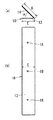
本実施形態のコーナーキャビネット1は、図1、図2に示すように、部屋のコーナー部2に設置される直方体収納ボックス5と、上記直方体収納ボックス5の前面開口部6を挟んでその左右両側に配置される側板7,8と、上記直方体収納ボックス5の上部から左右の側板7,8の上部に跨って覆う平面視五角形の天板9とで構成されていると共に、これら直方体収納ボックス5と左右の側板7,8と天板9は、それぞれ、分解・組立可能な別部品にて構成される。図1中の5cは直方体収納ボックス5の上面部、20はフラップダウン扉、21は配線パイプ、22は扉22aを備えるサイドボックスである。
As shown in FIGS. 1 and 2, the
上記TV40(図10、図11)を載置する天板9は、平面視略L字形に形成されており、直方体収納ボックス5の上部から左右の側板7,8の上部に跨って覆う五角形状部とサイドボックス22の上部を覆う四角形部9Aとが面一状に連続して一体形成されている。
The
図2において、天板9は、コーナー部2の直交する壁面3,4に沿う背部二辺9a,9bと、左右の側板7,8に沿う側部二辺9c,9dと、キャビネット本体5の前面開口部6に沿う前部斜辺9eとを有する平面視五角形に形成されている。なお、上記各辺9a,9b,9c,9d,9eを有するものであれば、例えば、五角形以上の多角形であってもよい。
In FIG. 2, the
本例では、天板9の背部二辺9a,9bが、図3に示すように、一対の棒状の受け金具12,12を介して、コーナー部2の壁面3、4に対してそれぞれ固定支持されており、これにより天板5の安定支持が図られている。なお天板9の中央側には、TV用配線キャップが装着される配線切欠孔41が設けられ、例えばプラズマTVや液晶TVの薄型TVが設置可能とされる。
In this example, the two
上記直方体収納ボックス5の前面開口部6は、図6に示すように、平面視でコーナー部2の壁面3,4に対して所定角度θ、例えば45°で傾斜した状態(部屋の中央側から見て正面向き)で配置されている。
As shown in FIG. 6, the front opening 6 of the rectangular
上記直方体収納ボックス5の左右に配置される側板7,8のうち、一方の側板7は、その幅方向Aの一側端部7aがコーナー部2の一方の壁面3に直交して接触した状態で、幅方向Aの他側端部7bが平面視略V字形の第1の連結具10を介して該一方の壁面3と対向する直方体収納ボックス5の一方の前側端部5aに対して所定角度αで傾斜して連結保持されている。
Of the
他方の側板8は、その幅方向Aの一側端部8aがコーナー部2の他方の壁面4に直交して接触した状態で、幅方向Aの他側端部8bが平面視略V字形の第2の連結具11を介して該他方の壁面4と対向する直方体収納ボックス5の他方の前側端部5bに対して所定角度βで傾斜して連結保持されている。
The
本例では、一方の壁面3に沿う一方の側板7が化粧パネルとして機能し、他方の壁面4に沿う他方の側板8が補強パネルとして機能する。
In this example, one
上記第1の連結具10は、図4に示すように、側板7の内面に取り付けられる側板取付片14と、直方体収納ボックス5の一方の前側端部5aに取り付けられるボックス取付片13とがα(略45°)のV字形角度をつけて平面視略V字形に形成されている。第2の連結具11は、図5に示すように、側板7の内面に取り付けられる側板取付片14と、直方体収納ボックス5の他方の前側端部5bに取り付けられるボックス取付片13とがβ(略45°)のV字形角度をつけて平面視略V字形に形成されている。
As shown in FIG. 4, the
上記各連結具10,11のそれぞれの側板取付片14は、側板取付片14と直交する方向から見て側板取付片14の幅寸法Dが、ボックス取付片13の幅寸法Eよりも長く延ばしてあり、その長く延ばした部分に取付孔となるネジ孔16が形成されているので、連結具10(11)の側板取付片14とボックス取付片13とが平面視略V字形に形成されていても、ネジを側板取付片14のネジ孔16から側板7(8)に締結する際に、ボックス取付片13に邪魔されることなく、側板取付片14のネジ固定作業を容易に行なえるようになっている。またネジ孔16から締結されるネジが側板7(8)の外面に突出しないようにすることによって、側板7(8)の外観が良好に保たれるようになっている。
Each of the side
一方、各連結具10(11)のそれぞれのボックス取付片13には、複数の貫通孔18が形成されていると共に、直方体収納ボックス5の前側端部5aには、棚板保持用のダボ(図示せず)が圧入可能な既成のダボ穴17が複数設けられており、直方体収納ボックス5の内側から固定部材であるタッピンネジ19をダボ穴17を通してボックス取付片13の貫通孔18に締結することによって、側板取付片14を直方体収納ボックス5の前側端部5aに引き寄せて固定できるようになっている。
On the other hand, a plurality of through
なお、上記図4、図5の例では、側板取付片14の幅寸法Dをボックス取付片13よりも長く延ばした例を示しているが、勿論これに限らず、例えば側板取付片14の長さ寸法(図4(b)、図5(b)の上下方向)をボックス取付片13の長さ寸法よりも長く延ばし、この長く延ばした部分にネジ孔16を形成してもよいものである。
4 and 5 show an example in which the width dimension D of the side
次に、部屋の形状や置き物の配置等に合わせて直方体収納ボックス5の前面開口部6を正面向きから右向き或いは左向きに変える際は、左右の側板7,8と連結具10,11を別仕様のものと交換すればよい。
Next, when changing the
つまり、図6に示すように、直方体収納ボックス5の前面開口部6がコーナー部2の一方の壁面4に対して所定角度θ(例えば45°)で傾斜した状態(部屋中央部から見て正面向き)に配置される場合は、V字形角度α,βが45°をした一対の連結具10,11と、幅寸法が等しい左右の側板7,8とを、組み合わせて用いる。また図7に示すように、直方体収納ボックス5の向きを例えば50°の左向きの傾斜角度(θ’)に変更する場合は、V字形角度α’,β’が50°と40°の2つの連結具10’,11’と、幅狭の側板7’と幅広の8’とを、組み合わせて用いる。また図8に示すように、直方体収納ボックス5の向きを例えば60°の右向きの傾斜角度(θ”)に変更する場合は、V字形角度α”,β”が60°と30°の2つの連結具10”,11”と、幅広の側板7”と幅狭の側板8”とを、組み合わせて用いる。つまり、直方体収納ボックス5の向きに応じて、V字形角度α,β(α’,β’:α”,β”)の合計角度が90°となる2つの連結具の組み合わせを選択し、さらに、幅寸法の異なる側板7,8の組み合わせを選択すればよい。勿論、直方体収納ボックス5の向きは上記45°、50°、60°に限らず、任意の角度に適宜設定変更可能である。
That is, as shown in FIG. 6, the
次に、本発明の平面視五角形のコーナーキャビネット1を組み立てるにあたっては、先ず、一方の側板7の内面に第1の連結具10の側板取付片14を取り付け、第1の連結具10のボックス取付片13を直方体収納ボックス5の一方の前側端部5aに取り付ける。さらに、他方の側板8の内面に第2の連結具11の側板取付片14を取り付け、第2の連結具11のボックス取付片13を直方体収納ボックス5の他方の前側端部5bに取り付ける。なお、一方の側板7と他方の側板8の取り付け手順はこれには限定されない。その後、天板9の背部二辺9a,9bをコーナー部2の直交する壁面3,4に沿わせ、側部二辺9c,9dを左右の側板7,8の上部に沿わせ、前部斜辺9eを前面開口部6の上部に沿わせるようにして、天板9を直方体収納ボックス5の上面5cに載置する。
Next, in assembling the
これにより、別部品からなる直方体収納ボックス5と左右の側板7,8と連結具10,11と天板9との組み合わせによって、少ない部品数で平面視五角形のコーナーキャビネット1を容易に組み立てることができる。
Thereby, the
また、上記天板9の背部二辺9a,9bをコーナー部2の壁面3,4にぴったりと合わせることができるので、見栄えがきわめて良好に保たれる利点もある。
In addition, since the back two
また本例では、平面視略V字形の連結具10,11を用いて側板7,8を直方体収納ボックス5に対して連結するにあたって、側板取付片14の幅寸法Dをボックス取付片13の幅寸法Eよりも長く延ばし、その長く延ばした部分にネジ孔16を形成してあるので、側板取付片14と直交する方向からネジを側板取付片14のネジ孔16から側板7(8)にネジ込む際に、ボックス取付片13に邪魔されることなく、側板取付片14の取付作業を容易に行なえるようになる。またこのときネジが側板7(8)を貫通しないようにすることで、側板7(8)の外観低下を防止できる。
Further, in this example, when the
また本例では、ボックス取付片13に、直方体収納ボックス5の前側端部5aに設けられた既成のダボ穴17と連通する貫通孔18を形成し、直方体収納ボックス5の内側からタッピンネジ19を該ダボ穴17を通して貫通孔18に締結できるので、既成のダボ穴17を利用してボックス取付片13の取付作業を楽に行なえると共に、直方体収納ボックス5への穴加工が不要となり、取付作業が一層はかどる利点もある。
Further, in this example, the
さらに本例では、直方体収納ボックス5の横方向に隣接してサイドボックス22を設置し、サイドボックス22の上部を覆う四角形天板部9A(図1、図2の斜線部分)を天板9に一体に形成している。これにより、例えば図11に示すように、四角形天板部9Aによってユニットボックス45上に立設される背の高い収納ラック46にTV40に近接することもなく、TV40の視野が広がり、TV40の首振り角度も広く確保できるようになる。なお図11の例では、四角形天板部9Aの上面には、TV40の妨げとならない程度の比較的細幅の小物ラックユニット30を設置しており、これにより四角形天板部9Aの上面部分がデットスペースになることがなく、有効利用が図られる。なお図10、図11中の45は中央側の収納ボックス、9Bはその収納ボックス45を覆う四角形天板部であって四角形天板部9Aと連続して一体に形成されており、天板9,9A,9B全体の外観が良く且つ製造コストを安価にできる利点もある。
Furthermore, in this example, the
前記実施形態ではキャビネット本体5の右側にサイドボックス22を配置した例を説明したが、左側に配置した構造でもよい。この場合において、図12(a)は右仕様の天板9,9A、図12(b)は左仕様の天板9,9Aの例を示している。
In the above-described embodiment, the example in which the
前記実施形態では第1及び第2の連結具10,11として平面視略V字形のものを例示したが、他例として、例えば連結具を断面三角形状の棒状体、或いは、断面三角形状のピース片を一定間隔で配置したものであってもよい。要するに、連結具における側板に取り付けられる側の面と直方体収納ボックスに取り付けられる側の面との角度が所定角度で傾斜したものであればよく、その形状は特に問わない。
In the above-described embodiment, the first and
1 コーナーキャビネット
2 コーナー部
3 一方の壁面
4 他方の壁面
5 直方体収納ボックス
5a 一方の前側端部
5b 他方の前側端部
6 前面開口部
7 一方の側板
7a 一側端部
7b 他側端部
8 他方の側板
8a 一側端部
8b 他側端部
9 天板
9a,9b 背部二辺
9c,9d 側部二辺
9e 前部斜辺
10 第1の連結具
11 第2の連結具
13 側板取付片
14 ボックス取付片
16 ネジ孔
17 ダボ穴
18 貫通孔
19 固定部材
A 幅方向
θ 直方体収納ボックスの傾斜角度
DESCRIPTION OF
Claims (5)
A method of assembling a corner cabinet installed in a corner of a room, comprising a rectangular parallelepiped storage box in plan view, side plates disposed on both right and left sides of the front opening of the rectangular parallelepiped storage box, And a second connector, and a top plate having two back sides along the orthogonal wall surface of the corner portion, two side portions along the left and right side plates, and a front oblique side along the front opening. One side of the first connector is attached to the inner surface of one side plate, one side of the second connector is attached to the inner surface of the other side plate, and one front end of the cuboid storage box from the inside of the cuboid storage box Is attached to the other surface of the first connector, the other front end of the rectangular parallelepiped storage box is attached to the other surface of the second connector, and then the two back sides of the top plate are attached to the orthogonal wall surface of the corner portion. Along A corner cabinet characterized in that the top plate is placed on the upper surface of the rectangular parallelepiped storage box so that the two sides are along the top of the left and right side plates and the front oblique side is along the top of the front opening. Assembly method.
Priority Applications (1)
| Application Number | Priority Date | Filing Date | Title |
|---|---|---|---|
| JP2008298701A JP5044533B2 (en) | 2008-11-21 | 2008-11-21 | Corner cabinet structure and assembly method thereof |
Applications Claiming Priority (1)
| Application Number | Priority Date | Filing Date | Title |
|---|---|---|---|
| JP2008298701A JP5044533B2 (en) | 2008-11-21 | 2008-11-21 | Corner cabinet structure and assembly method thereof |
Publications (2)
| Publication Number | Publication Date |
|---|---|
| JP2010119794A true JP2010119794A (en) | 2010-06-03 |
| JP5044533B2 JP5044533B2 (en) | 2012-10-10 |
Family
ID=42321653
Family Applications (1)
| Application Number | Title | Priority Date | Filing Date |
|---|---|---|---|
| JP2008298701A Expired - Fee Related JP5044533B2 (en) | 2008-11-21 | 2008-11-21 | Corner cabinet structure and assembly method thereof |
Country Status (1)
| Country | Link |
|---|---|
| JP (1) | JP5044533B2 (en) |
Cited By (1)
| Publication number | Priority date | Publication date | Assignee | Title |
|---|---|---|---|---|
| KR20220007380A (en) * | 2020-07-10 | 2022-01-18 | 주식회사 리노 | Shelf assembly for kitchen |
-
2008
- 2008-11-21 JP JP2008298701A patent/JP5044533B2/en not_active Expired - Fee Related
Cited By (2)
| Publication number | Priority date | Publication date | Assignee | Title |
|---|---|---|---|---|
| KR20220007380A (en) * | 2020-07-10 | 2022-01-18 | 주식회사 리노 | Shelf assembly for kitchen |
| KR102355986B1 (en) | 2020-07-10 | 2022-01-26 | 주식회사 리노 | Shelf assembly for kitchen |
Also Published As
| Publication number | Publication date |
|---|---|
| JP5044533B2 (en) | 2012-10-10 |
Similar Documents
| Publication | Publication Date | Title |
|---|---|---|
| JP2015026517A (en) | Nut press-fitting holding structure | |
| JP5044533B2 (en) | Corner cabinet structure and assembly method thereof | |
| JP2007310318A (en) | Thin display device | |
| US7918686B1 (en) | Server with improved connecting port | |
| JP2016205407A (en) | Joint unit and storage shelf | |
| JP4590478B2 (en) | Assembly shelf | |
| JP6558905B2 (en) | Bathroom counter | |
| JP5966753B2 (en) | Small portable devices | |
| US6729724B1 (en) | Spectacle lens holding structure | |
| JP2016206629A (en) | Display device | |
| JP5215824B2 (en) | Corner cabinet structure | |
| JP6262538B2 (en) | Building structure | |
| JP5106693B2 (en) | Television receiver and electronic device | |
| JP4945666B2 (en) | Television receiver | |
| JP5084030B2 (en) | Structure of the enclosure | |
| JP4278504B2 (en) | Connecting bracket | |
| JP2016213088A (en) | Substrate terminal | |
| JPH10137062A (en) | Cabinet rack | |
| JP4220915B2 (en) | System rack cabinet | |
| JP2018174658A (en) | Terminal board for video equipment | |
| US20130169123A1 (en) | Enclosure assembly | |
| JP2004165463A (en) | Frame joint structure | |
| JPH0438548Y2 (en) | ||
| JP2010147393A (en) | Mounting structure for flexible printed wiring board | |
| KR200417648Y1 (en) | Prefab Organizer |
Legal Events
| Date | Code | Title | Description |
|---|---|---|---|
| RD04 | Notification of resignation of power of attorney |
Free format text: JAPANESE INTERMEDIATE CODE: A7424 Effective date: 20100715 |
|
| A621 | Written request for application examination |
Free format text: JAPANESE INTERMEDIATE CODE: A621 Effective date: 20101217 |
|
| A711 | Notification of change in applicant |
Free format text: JAPANESE INTERMEDIATE CODE: A712 Effective date: 20120112 |
|
| TRDD | Decision of grant or rejection written | ||
| A01 | Written decision to grant a patent or to grant a registration (utility model) |
Free format text: JAPANESE INTERMEDIATE CODE: A01 Effective date: 20120619 |
|
| A01 | Written decision to grant a patent or to grant a registration (utility model) |
Free format text: JAPANESE INTERMEDIATE CODE: A01 |
|
| A61 | First payment of annual fees (during grant procedure) |
Free format text: JAPANESE INTERMEDIATE CODE: A61 Effective date: 20120713 |
|
| R150 | Certificate of patent or registration of utility model |
Ref document number: 5044533 Country of ref document: JP Free format text: JAPANESE INTERMEDIATE CODE: R150 Free format text: JAPANESE INTERMEDIATE CODE: R150 |
|
| FPAY | Renewal fee payment (event date is renewal date of database) |
Free format text: PAYMENT UNTIL: 20150720 Year of fee payment: 3 |
|
| LAPS | Cancellation because of no payment of annual fees |