JP2010101357A - Diaphragm valve device - Google Patents
Diaphragm valve device Download PDFInfo
- Publication number
- JP2010101357A JP2010101357A JP2008271453A JP2008271453A JP2010101357A JP 2010101357 A JP2010101357 A JP 2010101357A JP 2008271453 A JP2008271453 A JP 2008271453A JP 2008271453 A JP2008271453 A JP 2008271453A JP 2010101357 A JP2010101357 A JP 2010101357A
- Authority
- JP
- Japan
- Prior art keywords
- diaphragm
- main body
- valve device
- flange
- diaphragm valve
- Prior art date
- Legal status (The legal status is an assumption and is not a legal conclusion. Google has not performed a legal analysis and makes no representation as to the accuracy of the status listed.)
- Pending
Links
Images


Landscapes
- Valve Housings (AREA)
Abstract
【課題】ダイヤフラム弁装置における弁本体部を板厚に制約を受けることなく製作し、弁本体部すなわちダイヤフラム弁装置の軽量化、製造コストの低減化、研磨作業の軽減化による製造環境の改善。
【解決手段】ダイヤフラム3を弁本体部2へ膨出変位させ、弁本体部2内部を流動する流体の流通開口面積を制御するダイヤフラム弁装置1において、弁本体部2が、ダイヤフラム3が密着する着座部7,26,28を有する主体部8と、流入出の両フェルール9,10と、ダイヤフラム3を支持するフランジ11との四部品を具備し、かつ、これら四部品を金属の板材又はフープ材11,12から打ち抜き加工又はレーザ加工で得られたブランク14,23を形成し、該ブランクをプレス成型して得られた主体部8に両フェルール9,10およびフランジ11を溶接結合することにより弁本体部2を構成。
【選択図】図1
An object of the present invention is to manufacture a valve body portion in a diaphragm valve device without being restricted by the plate thickness, and to reduce the weight of the valve body portion, that is, the diaphragm valve device, reduce the manufacturing cost, and improve the manufacturing environment by reducing the polishing work.
In a diaphragm valve device (1) for controlling a flow opening area of a fluid flowing inside a valve body part (2) by bulging and displacing the diaphragm (3) to the valve body part (2), the valve body part (2) is in close contact with the diaphragm (3). It has four parts, a main part 8 having seating parts 7, 26, 28, both ferrules 9, 10 for inflow and outflow, and a flange 11 for supporting the diaphragm 3, and these four parts are made of metal plate or hoop. By forming blanks 14 and 23 obtained by punching or laser processing from the materials 11 and 12, and welding and joining the ferrules 9 and 10 and the flange 11 to the main body 8 obtained by press-molding the blanks. The valve body 2 is configured.
[Selection] Figure 1
Description
本発明は、医薬品、食品、酒類、化粧品、半導体等の製造設備の流体管路に配備されるダイヤフラム弁装置の改良に係り、殊に軽量化、製造環境の改善、製造コスト低減等を可能にしたダイヤフラム弁装置に関する。 The present invention relates to an improvement of a diaphragm valve device disposed in a fluid pipe of a manufacturing facility for pharmaceuticals, foods, alcoholic beverages, cosmetics, semiconductors, etc., and particularly enables weight reduction, improvement of manufacturing environment, reduction of manufacturing cost, etc. The present invention relates to a diaphragm valve device.
近年、例えばインターフェロンといった医薬品の製造設備に配備される配管には、弁装置としてバタフライ弁やボール弁ではなくダイヤフラム弁装置が多用される。これは、弁装置を洗浄する場合には、バタフライ弁やボール弁タイプでは、生産ラインを一時休止し、弁を分解して洗浄を行わなければならないのに対して、ダイヤフラム弁装置では分解しないで弁装置内を水蒸気や洗浄液を流すだけで簡易に洗浄が行え、生産ラインの停止を回避でき、生産メーカーの稼働効率を高められる利点があるからである。 In recent years, diaphragm valves, not butterfly valves and ball valves, are often used as piping for piping installed in pharmaceutical production facilities such as interferon. This means that when cleaning the valve device, the butterfly valve or ball valve type must suspend the production line and disassemble the valve to perform cleaning, whereas the diaphragm valve device does not disassemble it. This is because cleaning can be performed simply by flowing water vapor or cleaning liquid through the valve device, the stop of the production line can be avoided, and the operating efficiency of the manufacturer can be improved.
係るダイヤフラム弁装置としては除菌効果を有するステンレスを用いて製造される。この場合、ダイヤフラム弁装置の弁本体は、無垢のステンレスから切削、ボーリング等の多くの種類の機械加工を施して弁本体を削り出し、その後バフ研磨等の鏡面仕上げを行って所定の弁本体を製造していた。ところが、無垢のステンレスから弁本体を製造するには、複雑で熟練を要する機械加工や研磨工程を必要とするので、多くの作業工数を要し、加工コストが高くなる。また、弁本体の重量が相当に大きいため、作業者が製造過程で誤って落とした場合には、作業者に肉体的なダメージを与えかねない。 Such a diaphragm valve device is manufactured using stainless steel having a sterilizing effect. In this case, the valve body of the diaphragm valve device is machined from various types of machining, such as cutting and boring, from solid stainless steel, and then the mirror body finish such as buffing is applied to a predetermined valve body. It was manufactured. However, manufacturing a valve body from pure stainless steel requires complicated and skillful machining and polishing processes, which requires a large number of work steps and increases the processing cost. In addition, since the weight of the valve body is considerably large, if the operator accidentally drops it during the manufacturing process, the operator may be physically damaged.
そこで、軽量化を図る技術として特許文献1および特許文献2記載のものが知られている。これらはパイプ材をスタンプ部材とダイ部材との間にセットし、パイプ材の両端開口に押付部材を嵌入させた状態でスタンプ部材を上方へ進めてバルジ加工を行う。バルジ加工で得られた弁本体の環状カラー部と、パイプ材外周面とにフランジを溶接で結合することにより、弁構造体(弁本体部)を製造する技術である。
しかしながら、上記の特許文献1および特許文献2記載の弁構造体にあっては、プレス圧の制約からパイプ材の肉厚に制限があり、しかも、パイプ材しか用いて製作しなければならない制約を伴う。その結果、バルジ加工の要請からパイプ材の板厚が薄肉のものを採用せざるを得ず、その結果、強度が脆弱になる問題がある。また、環状カラー部は、パイプ表面からの立ち上がり寸法が極めて短いため、流体フランジに届き易くなり、フランジ周りへの流体成分の付着に起因する衛生上の問題を惹起する。また、フランジはカラー部の立ち上がり寸法が短いため、パイプ材の外周面に密接する。そのため、カラー部だけでなく、パイプ材外周面にもフランジを溶接で結合して固定しなければならないため、それだけ加工コストの上昇を招来する。
However, in the valve structure described in
本発明は、上記問題を解決するために工夫されたものであり、医薬品、食品、酒類、化粧品、半導体等のメーカーにおける製造設備の流体管路に配備されるダイヤフラム弁装置における弁本体部を板厚に制約を受けることなく製作できるので、弁本体部すなわちダイヤフラム弁装置の軽量化、製造コストの低減化を図れ、研磨作業の軽減化による製造環境の改善をも図ることができるダイヤフラム弁装置を提供するものである。 The present invention has been devised in order to solve the above-mentioned problem, and the valve body portion in the diaphragm valve device provided in the fluid conduit of the manufacturing equipment in manufacturers of pharmaceuticals, foods, alcoholic beverages, cosmetics, semiconductors, etc. A diaphragm valve device that can be manufactured without any restrictions on thickness, so that the valve body, that is, the diaphragm valve device can be reduced in weight and manufacturing cost can be reduced, and the manufacturing environment can be improved by reducing polishing work. It is to provide.
上記課題を解決するために、本発明においては次のような手段を講ずることとした。すなわち、請求項1の発明は、ダイヤフラムを弁本体部へ膨出変位させることにより、前記弁本体部内部を流動する流体の流通開口面積を制御するダイヤフラム弁装置において、前記弁本体部が、前記ダイヤフラムが密着する着座部を有する主体部と、該主体部の左右両側の同一線上に対向配置され、端部に継ぎ手部を設けた流入出の両管部材と、前記主体部の上方に設けられ前記ダイヤフラムを支持するフランジとの四部品を具備し、かつ、これら四部品を金属の板材又はフープ材から打ち抜き加工又はレーザ加工で得られたブランクを形成し、前記ブランクをプレス成型し、前記主体部に前記両管部材および前記フランジを溶接結合することにより前記弁本体部を構成したことを特徴とするダイヤフラム弁装置である。
In order to solve the above problems, the following measures are taken in the present invention. That is, the invention according to
請求項1の発明によれば、ダイヤフラム弁装置の弁本体部を構成する、主体部、一対の流入管部材と流出管部材、およびフランジの四部品を、金属の板材又はフープ材から打ち抜き加工又はレーザ加工によりブランクを形成した後、該ブランクをプレス成型する。プレス成型で得られた主体部に両管部材およびフランジを溶接結合することにより弁本体部を製作する。このため、従来のように無垢のステンレスから種々の機械加工により彫られて形成される弁本体部に比べて、四部品を溶接で結合するだけで弁本体部を形成できるので、弁本体部、すなわち、ダイヤフラム弁装置の大幅な軽量化、機械加工工数の大幅な低減による製作コストの低減を図れるようになる。また、金属の板材又はフープ材等、例えばステンレスの板材等を用いて製作するので、研磨工程を大幅に低減でき、その結果、マイクロポロシティの発生を抑制でき、表面に微細空孔の存しないダイヤフラム弁装置を得ることができる。さらに、特許文献1および特許文献2のバルジ加工で製作するものに比べて、強度の高い弁本体部を有するダイヤフラム弁装置を得ることができるようになる。
According to the first aspect of the present invention, the main part, the pair of inflow pipe members and the outflow pipe member, and the flange constituting the valve main body of the diaphragm valve device are punched from a metal plate or hoop material. After forming a blank by laser processing, the blank is press-molded. A valve body is manufactured by welding and joining both pipe members and a flange to the main body obtained by press molding. For this reason, compared to the valve body part that is carved by various machining processes from solid stainless steel as in the past, the valve body part can be formed by simply joining the four parts by welding, so the valve body part, That is, the manufacturing cost can be reduced by drastically reducing the diaphragm valve device and greatly reducing the number of machining steps. In addition, since it is manufactured using a metal plate or hoop material, such as a stainless steel plate, the polishing process can be greatly reduced. As a result, the generation of microporosity can be suppressed, and the diaphragm has no fine pores on the surface. A valve device can be obtained. Furthermore, it is possible to obtain a diaphragm valve device having a valve body portion having a higher strength than those manufactured by bulging in
また、請求項2の発明は、ダイヤフラムを弁本体部へ膨出変位させることにより、前記弁本体部内部を流動する流体の流通開口面積を制御するダイヤフラム弁装置において、前記弁本体部が、前記ダイヤフラムが密着する着座部を有する主体部と、該主体部の左右両側の同一線上に対向配置され、端部に継ぎ手部を設けた流入出の両管部材と、前記主体部の上方に設けられ前記ダイヤフラムを支持するフランジとの四部品を具備し、かつ、前記主体部を、金属の板材又はフープ材から打ち抜き加工又はレーザ加工で得られたブランクを絞り加工により、前記両管部材を金属の板材又はフープ材から打ち抜き加工又はレーザ加工で得られたブランクを押し出しによるコイニング成形により、および、前記フランジを金属の板材又はフープ材から打ち抜き加工又はレーザ加工によりそれぞれ形成し、さらに、前記主体部に前記両管部材および前記フランジを溶接結合することにより前記弁本体部を構成したことを特徴とするダイヤフラム弁装置である。 According to a second aspect of the present invention, there is provided a diaphragm valve device for controlling a flow opening area of a fluid flowing inside the valve main body by bulging and displacing the diaphragm into the valve main body. A main body portion having a seating portion to which the diaphragm is in close contact; both inflow and outflow pipe members disposed on the same line on both the left and right sides of the main body portion and provided with joint portions at the end portions; and provided above the main body portion. It has four parts with a flange supporting the diaphragm, and the main part is made of a metal plate material or a hoop material by blanking or blanking obtained by laser processing, and the both pipe members are made of metal. A blank obtained by punching or laser processing from a plate material or hoop material is subjected to coining molding by extrusion, and the flange is formed from a metal plate material or hoop material. Each formed by punching or laser processing Chi, furthermore, a diaphragm valve device being characterized in that constitutes the valve body portion by welding coupling the two pipe members and said flange to said main portion.
この請求項2の発明によれば、主体部を絞り加工により、流入管部材と流出管部材をコイニング成形により、およびフランジを打ち抜き加工又はレーザ加工によりそれぞれ製作した後に、主体部に両管部材およびフランジを溶接結合して合体することで弁本体部を構成している。このため、従来のように無垢のステンレスから種々の機械加工により弁本体部を製作した態様のものに比べて、四部品を溶接結合するだけで弁本体部を形成できるので、弁本体部の大幅な軽量化、機械加工工数および研磨作業の大幅な省力化等による製作コストの低減を図ることができるようになる。また、特許文献1および特許文献2のバルジ加工で製作するものに比べて、強度の高い弁本体部を有するダイヤフラム弁装置を得ることができるようになる。
According to the second aspect of the present invention, after the main portion is manufactured by drawing, the inflow pipe member and the outflow pipe member are manufactured by coining, and the flange is formed by punching or laser processing, the two main pipe members and The valve main body is configured by welding and combining the flanges. For this reason, the valve body can be formed by simply welding and joining the four parts, compared to the conventional case where the valve body is manufactured from solid stainless steel by various machining processes. The manufacturing cost can be reduced by reducing the weight, machining man-hours, and the significant labor saving of the polishing work. Further, it is possible to obtain a diaphragm valve device having a valve body portion having higher strength than those manufactured by bulge processing of
また、請求項3の発明は、請求項1または2記載のダイヤフラム弁装置に係り、前記両管部材の継ぎ手部を、フェルールとして形成したことを特徴とする。
この請求項3の発明によれば、ダイヤフラム弁装置をフェルール接続することで配管系に容易に取り付けることができるようになる。
The invention according to
According to the third aspect of the present invention, the diaphragm valve device can be easily attached to the piping system by ferrule connection.
また、請求項4の発明は、請求項3記載のダイヤフラム弁装置に係り、前記両フェルールは、前記絞り加工により形成された前記主体部の両側に穴を穿ち、該穴を玉抜き加工により前記主体部外方に出っ張らせて接続部を形成し、該接続部に前記各フェルールを溶接で結合したことを特徴とする。
The invention according to claim 4 relates to the diaphragm valve device according to
この請求項4の発明によれば、玉抜き加工により形成される接続部にフェルールを溶接結合することで、主体部とフェルールとが連通する。このため、従来のように主体部とフェルールとの流体流通路をドリル加工で穿って形成する熟練を要する作業手間を省略でき、大幅に製作能率を向上できるようになる。 According to the fourth aspect of the present invention, the main part and the ferrule communicate with each other by welding the ferrule to the connection part formed by the beading process. For this reason, it is possible to omit the labor-intensive work required to drill and form the fluid flow path between the main body and the ferrule as in the prior art, and the production efficiency can be greatly improved.
また、請求項5の発明は、請求項1〜4のいずれか一項に記載のダイヤフラム弁装置に係り、前記フランジは、前記玉抜き加工により前記接続部を形成するときに同時形成される立ち上がり部に、前記主体部に接触することなく浮き上がった状態で溶接結合されることを特徴とする。
The invention of claim 5 relates to the diaphragm valve device according to any one of
この請求項5の発明によれば、フランジを結合する立ち上がり部は主体部に接触することなく浮き上がった状態、換言すると、主体部から上方へ所定の長さ立ち上がった状態で形成される。このため、特許文献1および特許文献2のものに比べて、立ち上がり部を長く設定された主体部を形成できる。このため、フランジを立ち上がり部に取り付ける場合に、フランジを主体部の外周面に溶接結合することなく、立ち上がり部に溶接するだけで主体部に結合することができる。その結果、溶接工数の低減を図れ、プロセス流体や洗浄液等の流体がフランジ周りに届きにくくなり、流体が付着してフランジとダイヤフラムとが密着する隙間に固化して堆積するのを抑制できるようになる。
According to the fifth aspect of the present invention, the rising portion that joins the flange is formed in a state of being lifted without contacting the main body portion, in other words, in a state of rising from the main body portion by a predetermined length. For this reason, compared with the thing of
また、請求項6の発明は、請求項1〜5のいずれか一項に記載のダイヤフラム弁装置に係り、前記着座部は、前記流体の流動する方向にほぼ直交し、かつ、少なくとも前記ダイヤフラムの中心軸線方向に対向する前記主体部の最深部近傍を、前記両フェルールの内周面と略同じ面上で連続するように形成したことを特徴とする。 A sixth aspect of the present invention relates to the diaphragm valve device according to any one of the first to fifth aspects, wherein the seating portion is substantially orthogonal to a direction in which the fluid flows, and at least of the diaphragm. It is characterized in that the vicinity of the deepest part of the main part facing in the central axis direction is formed so as to be continuous on substantially the same surface as the inner peripheral surfaces of the ferrules.
この請求項6の発明によれば、着座部の最深部近傍を左右両フェルールの内周面と略同じ面上で連続させ、流量抵抗が小さくなるように形成している。このため、ダイヤフラム開弁時には、流体(プロセス流体、洗浄液等)を流入フェルールから流出フェルールへ滞留することなく円滑に流動させることができる。したがって、流体を主体部の流通横断面を上下に亘ってフルに流動させるのではなく、比較的下方部位を流動させる態様で用いられるダイヤフラム弁装置に好適となる。また、ダイヤフラム閉弁時でも流体が最深部に滞留して付着固化するのを抑制できるようになる。 According to the sixth aspect of the present invention, the vicinity of the deepest portion of the seating portion is continued on substantially the same surface as the inner peripheral surfaces of the left and right ferrules so as to reduce the flow resistance. For this reason, when the diaphragm is opened, fluid (process fluid, cleaning liquid, etc.) can be smoothly flowed without staying from the inflow ferrule to the outflow ferrule. Therefore, it is suitable for a diaphragm valve device that is used in such a manner that the fluid does not flow fully across the flow cross section of the main portion, but rather flows in a relatively lower portion. Further, even when the diaphragm is closed, it is possible to suppress the fluid from staying in the deepest portion and being attached and solidified.
また、請求項7の発明は、請求項1〜6のいずれか一項に記載のダイヤフラム弁装置に係り、前記着座部は、流体の流動方向に略直交する方向に、内方へ膨出する微少な隆起部を対向配置し、該一対の隆起部の間に前記ダイヤフラムが密着することを特徴とする。 A seventh aspect of the invention relates to the diaphragm valve device according to any one of the first to sixth aspects, wherein the seating portion bulges inward in a direction substantially perpendicular to the fluid flow direction. Minute ridges are arranged opposite to each other, and the diaphragm is in close contact between the pair of ridges.
この請求項7の発明によれば、一対の隆起部を形成したので、ダイヤフラムは位置ズレすることなくスムーズに着座して密着するので、ダイヤフラムの完全閉止を確実に行えるようになる。 According to the seventh aspect of the present invention, since the pair of raised portions are formed, the diaphragm can be seated and adhered smoothly without being displaced, so that the diaphragm can be surely completely closed.
また、請求項8の発明は、請求項1〜6記載のダイヤフラム弁装置に係り、前記着座部は、流体の流動方向に沿う縦断面形状が内方へ山形に、かつ、流体の流動方向に略直交する方向に突出させ、該山形の頂部に前記ダイヤフラムが密着することを特徴とする。
The invention according to
この請求項8の発明によれば、着座部を最深部から内方へ出っ張るように縦断面山形に形成したので、流体を主体部の流通横断面一杯に流動させる態様のダイヤフラム弁装置にも適用可能となる。このため、ダイヤフラム閉時には流体の流動をダイヤフラムと着座部とにより完全に堰き止めることができ、ダイヤフラム開時には着座部の高さ分だけ流体の流れを堰き止めることができる。 According to the eighth aspect of the present invention, the seating portion is formed in a mountain shape with a vertical cross section so as to protrude inward from the deepest portion, so that it can also be applied to a diaphragm valve device having a mode in which the fluid flows to the full flow cross section of the main portion. It becomes possible. For this reason, when the diaphragm is closed, the fluid flow can be completely blocked by the diaphragm and the seating portion, and when the diaphragm is opened, the fluid flow can be blocked by the height of the seating portion.
また、請求項9の発明は、請求項8記載のダイヤフラム弁装置に係り、前記着座部に対応する前記主体部の外側の凹部に、金属の板材又はフープ材から打ち抜き加工又はレーザ加工で形成したスペーサを溶接で結合したことを特徴とする。
The invention according to
請求項8の発明によれば、凹部にスペーサを設けることで、主体部を含めた弁本体部の曲げ剛性を高めることができるようになる。
According to the invention of
本発明によれば、医薬品、食品、酒類、化粧品、半導体等のメーカーにおける製造設備の流体管路に配備されるダイヤフラム弁装置にあって、ダイヤフラム弁装置の衛生確保、軽量化、製造コストの低減化、研磨仕上げの大幅削減化、製造過程における落下に起因する作業者に与えるダメージの未然回避等を図ったダイヤフラム弁装置を得ることができる。 According to the present invention, there is a diaphragm valve device installed in a fluid pipe of a manufacturing facility in a manufacturer of pharmaceuticals, foods, alcoholic beverages, cosmetics, semiconductors, etc., and the sanitary ensuring, weight reduction, and manufacturing cost reduction of the diaphragm valve device A diaphragm valve device can be obtained in which the reduction of the polishing, the sharp reduction of the polishing finish, the avoidance of damage caused to the worker due to the fall in the manufacturing process, and the like can be obtained.
以下、本発明を実施するための最良の形態を、図面に示す実施形態に基づいて詳述する。図1は実施形態に係るダイヤフラム弁装置1の組み立て分解を示す斜視図、図2は弁本体部2の組み立て分解を示す正面図、図3(a)は弁本体部2の平面図、同図(b)はその正面図、図4は図3(b)のA−A線における矢視断面図である。
Hereinafter, the best mode for carrying out the present invention will be described in detail based on the embodiments shown in the drawings. FIG. 1 is a perspective view showing assembly / disassembly of the
ダイヤフラム弁装置1の基本形態は図1に示すように、弁本体部2,ダイヤフラム3,アクチュエータ4を主要構成要素とし、これら三者2〜4をボルト5,ワッシャ6により一体に結合してダイヤフラム弁装置1が組み立てられる。本実施形態ではアクチュエータ4は手動タイプであるが、勿論自動タイプであってもよい。また、ダイヤフラム3は自体公知のもので、例えば、ゴムとテフロン(登録商標)部とを重ねてパッキン兼用のダイヤフラム膜が形成され、後述する弁本体部2の着座部に密着させてプロセス流体の流動を遮断する機能の他に、流体が外部へ漏洩しないように形成される。
As shown in FIG. 1, the basic form of the
上記の弁本体部2は図2のように、ダイヤフラム3が密着する着座部7を有する主体部8と、該主体部8の左右両側の同一線上に対向配置され、端部にフェルールを設けた管部材としての流入フェルール9および流出フェルール10と、主体部8の上方に設けられダイヤフラム3を載せて支持するフランジ11との四部品で構成される。これら四部品8〜11は、金属の板材又はフープ材から打ち抜き加工又はレーザ加工でブランクを形成し、該ブランクをプレス成型する。このプレス成型で得られた各部品を互いに溶接結合で合体して、図3に示す形態に組み立てられる。なお、本実施形態ではステンレスの板材を素材として用いる場合を例に挙げて説明する。
As shown in FIG. 2, the
以下、上記のフランジ11、主体部8、およびフェルール9、10の製作を、模式的に表した図5〜図7(a)に基づいて説明する。なお、上記の各部品は冷間加工により行われるものであるが、特に係る条件に限定されるものでないのは言うまでもない。
Hereinafter, the production of the
(フランジの加工)
フランジ11は図5(a)に示すように、ステンレスの板材12をプレス打ち抜き加工により製作される。これにより、ダイヤフラム3が主体部8へ膨出変位するのを許容する穴11a、ボルト5を挿入するボルト孔11bが形成され、ダイヤフラム3の載置が可能となる。
(Flange processing)
As shown in FIG. 5A, the
(主体部の加工)
次に、主体部8の加工を説明する。主体部8は図5(b)および図6に示されるように、ステンレス材の板材13から絞り成形が可能な形状に打ち抜き加工又はレーザ加工でブランク材14を加工する(ブランク工程)。得られたブランク材14はプレス機械にセットされ、絞り加工(プレス成型)が施される。絞り加工工程では、主体部8は、符号8a、8b、8cで示す過程を経て製作される。これは、ステンレス材は一度の加工では素材が破断してしまう、すなわち、ステンレス材は特に加工硬化が大きい素材であるため、素材に負荷を与えることなく加工する必要があるために数回に分けて加工を行う。これにより、所定深さ、内面形状を備えた主体部8を得ることができる。
(Machining of main part)
Next, processing of the
なお、本発明者は係る工程内における金型の形状を経験的に予測できる。すなわち、ダイヤフラム弁装置の用途に応じ、ステンレス材の板厚、深しぼりの度合い等に応じて経験的に金型形状を製作できる。こうして、係る知見に基づき、主体部8を数回に亘る絞り加工により、複雑な内部凹凸形状を有する主体部8でも製作が可能となる。
The inventor can empirically predict the shape of the mold in the process. That is, according to the use of the diaphragm valve device, the mold shape can be empirically manufactured according to the thickness of the stainless steel material, the degree of deepening, and the like. Thus, based on such knowledge, the
上記絞り加工により得られた主体部8の内面には、ダイヤフラム3が着座する着座部7が同時に成形される。この着座部7は図1,図3(b)に示すように、流体(プロセス流体)が流動する方向にほぼ直交し、かつ、少なくともダイヤフラム3の中心軸線方向に対向する主体部の最深部近傍を、両フェルール9,10の内周面と略同じ面上で連続するように形成される。換言すると、玉抜きによる穴18の内径をフェルール9の内径と略同一とすることにより、主体部の最深部近傍を、両フェルールの内周面と略同じ面上で連続するように形成される。これにより、着座部7近傍における流体の流動抵抗が小さく、残留することなく流入フェルール9から流出フェルール10へ流動できるようになっている。
A
また、着座部8には、流体の流動方向に略直交する方向に、内方へわずかに膨出する隆起部15、16が対向配置され、該一対の隆起部15,16の間の略平坦な水平面をなす着座部7の央部にダイヤフラム3が膨出して降りてきた場合に密着するようになっている。
Further, the
ところで、図6(a)に示すように、絞り加工で得られた主体部8には、金型で挟持されたフランジ部17が残存する。そこで、図6(b)の点線で示すようにトリミング工程において、このフランジ部17から余分な部分を切除して、フランジ11と接合可能な形状にトリミングする。
By the way, as shown in FIG. 6A, the
次に、図6(c)に示されるように、主体部8にフェルール9,10を接合させるための穴明けが行われ、穴18が形成される。その後、図6(d)のようにコマ金型20を用いて玉抜き加工(バーリング加工)が施される。すなわち、コマ金型20を内側から外側へ引き抜くことにより、穴18が外側へ押し広げられ、図6(e)のようにフェルール9,10を接合させるための接続部21が形成される。
Next, as shown in FIG. 6C, a hole for joining the
このとき、主体部8には首状に立ち上がる立ち上がり部22も形成される。この立ち上がり部22は主体部8の本体部から所定長さを存して上方に突出する状態に形成され、フランジ11の下面が主体部の本体部から浮き上がって接触しないようになっている。
At this time, the
そして、図6(f)のように、左右の接続部21に溶接代を残した余分な部分が切削されて接続部21が仕上げられる。こうして、最終組み立て直前の主体部8が形成されることとなる。
Then, as shown in FIG. 6 (f), the excess portions that leave the welding allowances in the left and
(フェルールの加工)
フェルール9,10の加工を説明する。図7(a)のようにフェルールの素材は、ステンレスの板材をプレスによる打ち抜き加工によりリング状のブランク23が形成される。次いで、プレス押し出しと、冷間鍛造であるコイニング成形とにより素材23を潰しながら加工していき、仕上げ切削工程を経て、所定の流通横断面を有する鍔部24、25を備えた管状のフェルール9,10が形成される。こうして、図2のような主体部8、フェルール9,10、フランジ11が部品として得ることができる。
(Ferrule processing)
The processing of the
(溶接工程)
部品である主体部8,フェルール9,10、およびフランジ11は、レーザ溶接またはTIG溶接により接合(結合)される。具体的には、図3(b)に示すように、主体部8の接続部21にフェルール9,10が突き合わされ、その全周が溶接される。なお、図3(b)では主体部8とフェルール9,10との結合部を線で誇張して表示したが、実際にはこの線は溶接により現れない。
(Welding process)
The
また、主体部8の立ち上がり部22にフランジ11の穴11a(図5(a)参照)が合わされ、穴11aの内周が立ち上がり部22に溶接される。これにより、図1、図3(a)、図4に示すように開口縁部8aを有する弁本体部2が形成され、これにダイヤフラム3、アクチュエータ4を組み付けることでダイヤフラム弁装置1を得ることができる。なお、図4における符号Sは弁本体部2の流体通路を示す。
Further, the
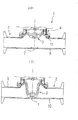
本実施形態におけるダイヤフラム弁装置1は上記のように構成されるので、図8(a)に示すように、アクチュエータ4によりダイヤフラム3が上方に収縮した状態にあるときは、流体は矢印の方向へ流動していく。図8(b)のようにダイヤフラム3が下方に膨出して着座部7密着した場合には、流体の流れは堰き止められる。
Since the
このように本実施形態によれば、主体部8を深絞り加工により形成するので、表面粗さが極めて細かく、鏡面仕上げに要する手間を大幅に省け、研磨時に生じる粉塵を最小限に抑えられる利点がある。また、弁本体部2はステンレスの板材からプレス打ち抜き加工等の打ち抜き加工やレーザ加工により形成するため、従来のように無垢のステンレス材を彫削して製作するものとは異なり、製作時間を大幅に短縮できるばかりか、軽量化を図れ、コスト安価なダイヤフラム弁装置を製作できる利点がある。また、立ち上がり部22へのフランジ11の溶接は必要最小限の溶接で済み、この点でも製作上有利となり、また、バルジ加工で製作する態様のものに比べて、立ち上がり部22を上方へ長く出っ張らせるので、流体が届きにくく、立ち上がり部22の存在によりフランジ11周りの剛性を高くできる利点等もある。
As described above, according to the present embodiment, the
また、上記実施形態によれば、主体部8をプレス成型により形成することで、主体部8とフランジ11とが溶接結合して形成されるフランジの内径、すなわちフェルール長手方向に直交する方向の内径にゆとりある寸法を有する弁本体部2が製作できる。そのため、主体部8両側には、内径の大小に制約を受けることなく、どのような内径のフェルール9,10も取り付けることができ、種々の内部流通抵抗を有するダイヤフラム弁装置を得ることができる。
Further, according to the above-described embodiment, by forming the
以上、本発明を実施形態により説明してきたが、具体的な構成は上記実施形態に限られるものでなく、本発明の要旨を逸脱しない範囲の設計変更等があっても本発明の範囲に含まれるものである。 As described above, the present invention has been described with reference to the embodiment. However, the specific configuration is not limited to the above embodiment, and design changes and the like without departing from the gist of the present invention are included in the scope of the present invention. It is what
例えば、上記実施形態では、素材をステンレスの板材を用いて説明したが、この代わりに、スーパーステンレス、ジュラルミン、チタン等やフープ材といった金属素材を用いることも可能である。 For example, in the above embodiment, the material has been described using a stainless steel plate, but instead, a metal material such as super stainless steel, duralumin, titanium, or a hoop material may be used.
また、上記弁本体部2では着座部7に一対の隆起部15,16を設け、その間を外方へわずかに膨出する曲面を有する断面形状としたが、図9に示すように内方へ凹む曲面を有する着座部26を有する変形例としてもよい。
Further, in the
また、フランジ11は板厚が薄かったが、図9のように肉厚のフランジ27を溶接することも可能である。
Further, although the
また、図10に示す変形例のように、着座部28を、流体の流動方向に沿う縦断面形状が内方へ山形に形成し、かつ、流体の流動方向に略直交する方向に突出させ、該山形の頂部29にダイヤフラム3が密着するように構成してもよい。係る変形例によれば、着座部28が最深部から内方へ出っ張るように縦断面山形に形成されるので、流体を主体部8の流通横断面一杯に流動させる態様のダイヤフラム弁装置にも適用できる。これによれば、ダイヤフラム開時でも流体の流れを着座部28で堰き止めることができる。
Further, as in the modification shown in FIG. 10, the
なお、この場合、着座部29に対応する主体部8の外側に形成される凹部30に、図7(b)に示すようにステンレス31から凹部30に見合う形状にプレス打ち抜き加工したスペーサ32を嵌め込んで溶接結合してもよい。これにより、着座部29周辺の剛性を高めることができる。
In this case, a
また、上記実施形態および変形例では、管部材における継ぎ手部としてはフェルール接合されるフェルールを有する場合について説明したが、この代わりにIDF規格のユニオンを設けた管部材、あるいはネジ締結による継ぎ手部等の態様であってもよい。 In the above-described embodiment and the modification, the case where the pipe member has a ferrule joined as a joint has been described. However, instead of this, a pipe member provided with an IDF standard union, a joint portion by screw fastening, or the like The aspect of this may be sufficient.
本発明は、医薬品、食品、酒類、化粧品、半導体等の製造設備の流体管路に配備されるダイヤフラム弁装置に適用できる。 The present invention can be applied to a diaphragm valve device provided in a fluid pipe of a manufacturing facility for pharmaceuticals, foods, alcoholic beverages, cosmetics, semiconductors and the like.
1 ダイヤフラム弁装置
2 弁本体部
3 ダイヤフラム
4 アクチュエータ
7 着座部
8 主体部
9,10 フェルール
11 フランジ
12、13 ステンレスの板材
14 ブランク
15,16 隆起部
18 穴
21 接続部
22 立ち上がり部
23 ブランク
32 スペーサ
26 着座部
27 フランジ
28 着座部
29 頂部
30 凹部
S 流体流路
DESCRIPTION OF
Claims (9)
Priority Applications (1)
| Application Number | Priority Date | Filing Date | Title |
|---|---|---|---|
| JP2008271453A JP2010101357A (en) | 2008-10-21 | 2008-10-21 | Diaphragm valve device |
Applications Claiming Priority (1)
| Application Number | Priority Date | Filing Date | Title |
|---|---|---|---|
| JP2008271453A JP2010101357A (en) | 2008-10-21 | 2008-10-21 | Diaphragm valve device |
Publications (1)
| Publication Number | Publication Date |
|---|---|
| JP2010101357A true JP2010101357A (en) | 2010-05-06 |
Family
ID=42292184
Family Applications (1)
| Application Number | Title | Priority Date | Filing Date |
|---|---|---|---|
| JP2008271453A Pending JP2010101357A (en) | 2008-10-21 | 2008-10-21 | Diaphragm valve device |
Country Status (1)
| Country | Link |
|---|---|
| JP (1) | JP2010101357A (en) |
Cited By (3)
| Publication number | Priority date | Publication date | Assignee | Title |
|---|---|---|---|---|
| KR20220050546A (en) * | 2020-10-16 | 2022-04-25 | (주) 케이투앤 | Diaphragm valve reduced the residual fluid |
| CN116201924A (en) * | 2021-11-30 | 2023-06-02 | 宁波英科特精工机械股份有限公司上海分公司 | Diaphragm valve body and manufacturing method thereof |
| CN117570230A (en) * | 2024-01-19 | 2024-02-20 | 四川中油乐仪能源装备制造股份有限公司 | Axial flow type check valve |
Citations (7)
| Publication number | Priority date | Publication date | Assignee | Title |
|---|---|---|---|---|
| JPH0113663Y2 (en) * | 1981-10-30 | 1989-04-21 | ||
| JPH07132328A (en) * | 1993-11-12 | 1995-05-23 | Shinko Electric Ind Co Ltd | Coining method for metal parts |
| JPH10501466A (en) * | 1995-02-08 | 1998-02-10 | ビルケルト ベルケ ゲーエムベーハー ウント ツエーオー. | Method of manufacturing valve housing |
| JP2004344968A (en) * | 2003-05-26 | 2004-12-09 | Sango Co Ltd | Method for manufacturing burring worked part |
| JP2005347098A (en) * | 2004-06-03 | 2005-12-15 | Matsushita Electric Ind Co Ltd | Battery and battery assembly sealing plate |
| JP2007107692A (en) * | 2005-10-17 | 2007-04-26 | Time Engineering Co Ltd | Solenoid valve |
| JP2008128375A (en) * | 2006-11-21 | 2008-06-05 | Nomura Micro Sci Co Ltd | Valve and joint |
-
2008
- 2008-10-21 JP JP2008271453A patent/JP2010101357A/en active Pending
Patent Citations (7)
| Publication number | Priority date | Publication date | Assignee | Title |
|---|---|---|---|---|
| JPH0113663Y2 (en) * | 1981-10-30 | 1989-04-21 | ||
| JPH07132328A (en) * | 1993-11-12 | 1995-05-23 | Shinko Electric Ind Co Ltd | Coining method for metal parts |
| JPH10501466A (en) * | 1995-02-08 | 1998-02-10 | ビルケルト ベルケ ゲーエムベーハー ウント ツエーオー. | Method of manufacturing valve housing |
| JP2004344968A (en) * | 2003-05-26 | 2004-12-09 | Sango Co Ltd | Method for manufacturing burring worked part |
| JP2005347098A (en) * | 2004-06-03 | 2005-12-15 | Matsushita Electric Ind Co Ltd | Battery and battery assembly sealing plate |
| JP2007107692A (en) * | 2005-10-17 | 2007-04-26 | Time Engineering Co Ltd | Solenoid valve |
| JP2008128375A (en) * | 2006-11-21 | 2008-06-05 | Nomura Micro Sci Co Ltd | Valve and joint |
Cited By (5)
| Publication number | Priority date | Publication date | Assignee | Title |
|---|---|---|---|---|
| KR20220050546A (en) * | 2020-10-16 | 2022-04-25 | (주) 케이투앤 | Diaphragm valve reduced the residual fluid |
| KR102495988B1 (en) * | 2020-10-16 | 2023-02-06 | (주) 케이투앤 | Diaphragm valve reduced the residual fluid |
| CN116201924A (en) * | 2021-11-30 | 2023-06-02 | 宁波英科特精工机械股份有限公司上海分公司 | Diaphragm valve body and manufacturing method thereof |
| CN117570230A (en) * | 2024-01-19 | 2024-02-20 | 四川中油乐仪能源装备制造股份有限公司 | Axial flow type check valve |
| CN117570230B (en) * | 2024-01-19 | 2024-03-19 | 四川中油乐仪能源装备制造股份有限公司 | Axial flow type check valve |
Similar Documents
| Publication | Publication Date | Title |
|---|---|---|
| US8464566B2 (en) | Method of manufacturing a valve housing | |
| JP2000161519A (en) | Manufacture of flange type ball valve seat | |
| JP2010101357A (en) | Diaphragm valve device | |
| JP5046085B2 (en) | Method for manufacturing joining rod and cylinder device | |
| US9920843B2 (en) | Spring gasket for a valve housing | |
| US10518817B2 (en) | Method for producing a joint connection between a joint housing and a connection component and suspension component and chassis produced according to the method | |
| EP3044488B1 (en) | Valve housing with a spindle guide and method for production thereof | |
| JP6308428B2 (en) | Manufacturing method of metal fittings for fluid piping and metal fittings for fluid piping | |
| JP4775017B2 (en) | Method for manufacturing cylindrical member with protrusion | |
| KR101476795B1 (en) | Method of manufacturing fitting for high pressure hose | |
| JP2019209363A (en) | Two component joining method and closed section structural member assembling method | |
| JP5291375B2 (en) | Manufacturing method for vehicle wheel | |
| JP4971953B2 (en) | Ball valve | |
| JP2012242080A (en) | Water heater or the like, and method of manufacturing water heater or the like | |
| JP4577770B2 (en) | Manufacturing method for eye joint fittings | |
| KR20180012066A (en) | Welding Nut and Method for Fabricating the Same | |
| KR100666199B1 (en) | Manufacturing method of disk for butterfly valve | |
| WO2020235666A1 (en) | Hydraulic adapter unit, hydraulic pipe member, and hydraulic pipe member production method | |
| CN220060600U (en) | All-welded valve control ultrasonic metering assembly | |
| CN113195951A (en) | Method for manufacturing a block forged swing check valve body with a fully encapsulated seat ring | |
| JP2010127441A (en) | Actuator of valve device | |
| JP5930712B2 (en) | Beverage container fitting | |
| US20130276905A1 (en) | Valve housing for a vacuum valve | |
| JP5324396B2 (en) | Manufacturing method of valve body of diaphragm valve | |
| JP2005054967A (en) | Piping joint structure and manufacturing method thereof |
Legal Events
| Date | Code | Title | Description |
|---|---|---|---|
| A621 | Written request for application examination |
Free format text: JAPANESE INTERMEDIATE CODE: A621 Effective date: 20111004 |
|
| A977 | Report on retrieval |
Free format text: JAPANESE INTERMEDIATE CODE: A971007 Effective date: 20120802 |
|
| A131 | Notification of reasons for refusal |
Effective date: 20120904 Free format text: JAPANESE INTERMEDIATE CODE: A131 |
|
| A521 | Written amendment |
Effective date: 20121029 Free format text: JAPANESE INTERMEDIATE CODE: A523 |
|
| A521 | Written amendment |
Effective date: 20121029 Free format text: JAPANESE INTERMEDIATE CODE: A523 |
|
| A131 | Notification of reasons for refusal |
Effective date: 20130326 Free format text: JAPANESE INTERMEDIATE CODE: A131 |
|
| A02 | Decision of refusal |
Free format text: JAPANESE INTERMEDIATE CODE: A02 Effective date: 20130827 |