JP2010078985A - Sequential stereoscopic display device - Google Patents
Sequential stereoscopic display device Download PDFInfo
- Publication number
- JP2010078985A JP2010078985A JP2008247945A JP2008247945A JP2010078985A JP 2010078985 A JP2010078985 A JP 2010078985A JP 2008247945 A JP2008247945 A JP 2008247945A JP 2008247945 A JP2008247945 A JP 2008247945A JP 2010078985 A JP2010078985 A JP 2010078985A
- Authority
- JP
- Japan
- Prior art keywords
- eye
- image
- video
- frame
- display device
- Prior art date
- Legal status (The legal status is an assumption and is not a legal conclusion. Google has not performed a legal analysis and makes no representation as to the accuracy of the status listed.)
- Pending
Links
Images


Landscapes
- Liquid Crystal (AREA)
- Control Of Indicators Other Than Cathode Ray Tubes (AREA)
- Controls And Circuits For Display Device (AREA)
- Testing, Inspecting, Measuring Of Stereoscopic Televisions And Televisions (AREA)
- Liquid Crystal Display Device Control (AREA)
Abstract
Description
本発明は、シーケンシャル型立体表示装置に関する。 The present invention relates to a sequential type stereoscopic display device.
従来、立体表示装置の一形態として、表示装置に右眼用映像と左眼用映像を、時間的に交互に表示するシーケンシャル型立体表示装置が実用化されている。
このシーケンシャル型立体表示装置は、図4に示すように、鑑賞者301が各眼用映像の切り替えに同期して動作するシャッタを組み込んだシャッタメガネ302を装着する。
Conventionally, as one form of a stereoscopic display device, a sequential stereoscopic display device that displays a right-eye image and a left-eye image alternately in time on a display device has been put into practical use.
As shown in FIG. 4, the sequential type stereoscopic display device is equipped with
このシャッタメガネ302は、右眼用映像の表示期間のみ右眼用のシャッタが透過状態となるよう制御され、その結果、右眼は、右眼用映像だけを見ることができる。同様に、シャッタメガネ302は、左眼用の映像のみを見ることができるように制御される。この結果、鑑賞者301は、左右の眼で異なる映像を見ることになり、両眼視差により立体感を得ることができる。
The
上述のシーケンシャル型立体表示装置300は、左右の眼がシャッタメガネ302により、交互に瞬間的に塞がれることによりチラツキが発生する。人間がチラツキを感じなくなるためには、左右眼への映像の振り分けの周波数(以下、サブフレーム周波数という。)が少なくとも140Hz以上でなければならない。
In the above-described sequential type
例えば、近年の立体映画館では、映画のフレーム周波数24Hzに対して、右眼用映像と左眼用映像を交互に各3回ずつ表示することにより、サブフレーム周波数が24Hz×2×3=144Hzとなり、その結果、ほとんどチラツキを感じない画質レベルを実現している。 For example, in a recent 3D movie theater, a right-eye video and a left-eye video are alternately displayed three times each for a movie frame frequency of 24 Hz, so that the subframe frequency is 24 Hz × 2 × 3 = 144 Hz. As a result, an image quality level that hardly feels flickering is realized.
しかし、従来、フラットパネルディスプレイを用いたシーケンシャル型立体表示装置においては、画面全体に交互に右眼用画像と左眼用画像を表示して、これを光学的手段で左右の各眼に振り分ける方式であった。 However, conventionally, in a sequential stereoscopic display device using a flat panel display, a right-eye image and a left-eye image are alternately displayed on the entire screen, and this is distributed to the left and right eyes by optical means. Met.
このため、左右眼への映像提示の周波数は、ディスプレイのフレーム周波数に制限されることになり、液晶ディスプレイでは液晶応答速度の限界から、PDP(プラズマディスプレイ)では駆動周波数の限界から、いずれも十分なサブフレーム周波数を達成できず、チラツキ感を解決することができなかった。 For this reason, the frequency of video presentation to the left and right eyes is limited by the frame frequency of the display, which is sufficient from both the liquid crystal display speed limit of the liquid crystal display and the driving frequency limit of the PDP (plasma display). A sub-frame frequency could not be achieved, and flickering could not be solved.
本発明は、上述の実情を考慮してなされたものであって、フラットパネルディスプレイにおいて、チラツキを感じない立体表示を実現できるシーケンシャル型立体表示装置を提供することを目的とする。 The present invention has been made in consideration of the above situation, and an object of the present invention is to provide a sequential type 3D display device capable of realizing 3D display without feeling flicker on a flat panel display.
上述の課題を解決するために、本発明のシーケンシャル型立体表示装置は、右眼用映像と左眼用映像を時間的に交互に提示するシーケンシャル型立体表示装置であって、前記右眼用映像と前記左眼用映像が、異なる部分領域に透過率の変化として同時に書き込まれ、フレーム周波数間維持する透過型表示パネルと、前記右眼用映像と前記左眼用映像が書き込まれた前記部分領域を、前記フレーム周波数間で該フレーム周波数と異なる周波数で時間的に交互に照明するバックライトと、を備えている。 In order to solve the above-described problem, a sequential stereoscopic display device according to the present invention is a sequential stereoscopic display device that alternately presents a right-eye image and a left-eye image temporally, and the right-eye image is displayed. And the left-eye video are simultaneously written in different partial areas as a change in transmittance and maintained between frame frequencies, and the partial area in which the right-eye video and the left-eye video are written And a backlight that alternately illuminates temporally at a frequency different from the frame frequency between the frame frequencies.
上記シーケンシャル型立体表示装置において、前記右眼用映像と前記左眼用映像を書き込む部分領域は、(1)それぞれ隣接するラインに交互に固定的に割り当てられるか、または、(2)それぞれ隣接するラインに交互に割り当てられ、前記フレーム毎に逆順に交互に割り当てられるようにした。 In the sequential stereoscopic display device, the partial areas in which the right-eye video and the left-eye video are written are (1) alternately fixedly assigned to adjacent lines, or (2) are adjacent to each other. Alternatingly assigned to lines, and alternately assigned in reverse order for each frame.
本発明によれば、フラットパネルディスプレイにおいて、映像を表示するフレーム周波数とは独立に、十分高いサブフレーム周波数に設定できるので、チラツキを感じない立体表示を実現できるシーケンシャル型立体表示装置を提供できる。 According to the present invention, in a flat panel display, a sufficiently high subframe frequency can be set independently of a frame frequency for displaying an image. Therefore, it is possible to provide a sequential type stereoscopic display device capable of realizing a stereoscopic display without feeling flicker.
以下、図面を参照して本発明に係る好適な実施形態について説明する。
<実施形態1>
図1は、本発明に係るシーケンシャル型立体表示装置の概略構成を示す図である。
図1において、シーケンシャル型立体表示装置100は、入力部110、制御部120、データ取得部130、再生部140、右眼用映像記憶部145a、左眼用映像記憶部145b、同期制御部150、表示駆動部160、バックライト駆動部170、シャッタメガネ駆動部180、表示部190からなっている。
Hereinafter, preferred embodiments of the present invention will be described with reference to the drawings.
<Embodiment 1>
FIG. 1 is a diagram showing a schematic configuration of a sequential type stereoscopic display device according to the present invention.
In FIG. 1, a sequential
入力部110は、鑑賞者が行ったリモコン等の操作を受け付けて、受け付けた結果を制御部120に送信する。
制御部120は、入力部110から送られた鑑賞者の操作に応じて、当該装置100全体の制御を行う。
データ取得部130は、制御部120および再生部140からの指示にしたがって、DVDディスクやコンピュータ等から立体映像データを読み出す。
The
The
The
再生部140は、データ取得部130から読み出されたフレーム毎の立体映像データを復号し、右眼用の映像データを右眼用映像記憶部145aに、左眼用の映像データを左眼用映像記憶部145bに、フレーム毎の同期信号を同期制御部150に出力する。
The
右眼用映像記憶部145aおよび左眼用映像記憶部145bは、それぞれ1フレームの右眼用および左眼用の表示用ビデオイメージを保持するイメージバッファメモリである。
表示部190は、画素毎に光の透過率を制御するライトバルブとしての表示パネル190aと、上部に配置された表示パネル190aを発光して照明するバックライト190bとからなっている。
The right-eye
The
表示駆動部160は、同期制御部150からのフレーム毎の同期信号を受け取ると、右眼用映像記憶部145aに記憶した上部のラインから順番に映像データを取り出して、表示パネル190aの上部から奇数番のラインに対応させて透過率の変化として書き込み、同様に、左眼用映像記憶部145bに記憶した上部のラインから順番に映像データを取り出して、表示パネル190aの上部から偶数番のラインに対応させて透過率の変化として書き込み、フレーム周波数間で維持する。このときのフレーム周波数は、テレビの場合約60Hzが使用される。
Upon receiving the frame-by-frame synchronization signal from the
尚、映像データの大きさは、入力信号のフォーマットに依存して決まるが、表示パネルへ右眼用および左眼用の映像データを映像記憶部から取り出すときには、表示位置に対応した位置の映像データを取り出すようにする。
例えば、映像データと表示装置の垂直方向の解像度が一致している場合には、右眼用映像記憶部145aに記憶した上部の奇数番のラインから順番に映像データを取り出して、表示パネル190aの上部から奇数番のラインに対応させて書き込み、同様に、左眼用映像記憶部145bに記憶した上部の偶数番のラインから順番に映像データを取り出して、表示パネル190aの上部から偶数番のラインに対応させて書き込む。
The size of the video data is determined depending on the format of the input signal, but when the right-eye and left-eye video data is taken out from the video storage unit to the display panel, the video data at the position corresponding to the display position is used. To take out.
For example, when the video data and the vertical resolution of the display device match, the video data is sequentially extracted from the upper odd-numbered lines stored in the right-eye
また、垂直方向の映像データの解像度が表示パネル190aの解像度の半分でも、あるいは、一致したものでもないときには、垂直方向の表示パネル190aの解像度と一致するように、映像データを補間処理して、左眼用映像記憶部145bおよび右眼用映像記憶部145bに書き込んでおくようにすればよい。
Further, when the resolution of the video data in the vertical direction is half or not equal to the resolution of the
バックライト駆動部170は、同期制御部150からのフレーム毎の同期信号を受け取ると、フレーム周波数間において、例えば、140Hz以上に設定した周波数で第一の領域と第二の領域の発光を切り替えて、表示パネル190aの対応した領域を照明する。
この第一の領域は、表示パネル190aの奇数ラインに対応したバックライト190bの領域であり、第二の領域は、表示パネル190aの偶数ラインに対応したバックライト190bの領域である。
When the
The first area is an area of the
さらに、バックライト駆動部170は、この切り替えに同期して、発光が第一の領域のときには右眼を示す信号を、また、発光が第二の領域のときには左眼を示す信号をシャッタメガネ駆動部180に送信する。
Further, in synchronization with this switching, the
尚、バックライトを実現する方法としては次の方法がある。
(1)液晶や有機ELを線状領域にスダレ状に形成し、1ラインおきにグループを形成して発光制御する。
(2)光源としては、蛍光管またはLEDの平面均一光源をまず構成し、この前面に線状領域の液晶シャッタを形成し、1ラインおきにグループを形成してシャッタ制御する。
There are the following methods for realizing the backlight.
(1) A liquid crystal or an organic EL is formed in a linear shape in a linear shape, and a group is formed every other line to control light emission.
(2) As a light source, a flat uniform light source of a fluorescent tube or LED is first configured, a liquid crystal shutter of a linear region is formed on the front surface, and a group is formed every other line to perform shutter control.
シャッタメガネ駆動部180は、バックライト駆動部170の発光の切り替えに同期して、バックライト駆動部170からの信号をシャッタメガネ200に対して送信する。
シャッタメガネ200は、シャッタメガネ駆動部180から受信した信号に同期して、該信号が右眼を示していれば、右眼のみに映像が到達するように、透過状態になるように制御し、同様に、該信号が左眼を示していれば、左眼のみに映像が到達するように、透過状態になるように制御する。
The shutter
The
例えば、シャッタメガネ駆動部180では赤外線LED(発光ダイオード)から右眼または左眼を示す信号を送信し、シャッタメガネ200では、付属した受光器で、この信号を受信し、同期して鑑賞者の左右眼用のシャッタメガネのシャッタを交互に開閉する。
For example, the shutter
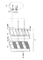
次に、図2を用いて、右眼用映像を鑑賞者に提示する状況を説明する。
この時、1フレーム毎の映像を表示する間、表示パネル190aの第一の領域(奇数ライン)には、右眼用の映像データが書き込まれ、第二の領域(偶数ライン)には左眼用の映像データが書き込まれている。また、バックライト190bの第一の領域(奇数ライン)と第二の領域(偶数ライン)とは、1フレームの映像を表示する間に、例えば140Hz以上の周波数で発光を繰り返す。
Next, a situation in which the right-eye video is presented to the viewer will be described with reference to FIG.
At this time, while displaying an image for each frame, video data for the right eye is written in the first area (odd line) of the
鑑賞者210は、シャッタメガネ200を装着しており、バックライト190bの発光を繰り返す周期に同期して、右眼用か、左眼用かに応じて対応した眼のみに映像が到達するように、シャッタメガネ200の開閉を制御する。
このように、表示パネル190aのフレーム周波数から独立に、バックライトの発光を切り替える周波数(140Hz以上に)を設定できるので、チラツキ感を減らすことができる。
The
Thus, since the frequency (to 140 Hz or higher) for switching the light emission of the backlight can be set independently of the frame frequency of the
以上のように実施形態1を構成することによって、バックライトの発光の切り替え周波数を表示パネルのフレーム周波数から独立に、十分に高い周波数に設定できるので、チラツキ感が減少する。 By configuring the first embodiment as described above, the switching frequency of the light emission of the backlight can be set to a sufficiently high frequency independently from the frame frequency of the display panel, thereby reducing flickering.
尚、上記の実施形態1では、右眼用の映像データを奇数番目のラインに、左眼用の映像データを偶数番目のラインに書き込むようにしたが、右眼用の映像データを偶数番目のラインに、左眼用の映像データを奇数番目のラインに書き込むようにしても構わない。 In the first embodiment, the right-eye video data is written in the odd-numbered lines and the left-eye video data is written in the even-numbered lines. However, the right-eye video data is written in the even-numbered lines. The left-eye video data may be written to the odd-numbered line in the line.
<実施形態2>
上記の実施形態1では、右眼用映像および左眼用映像を表示パネル190aの奇数ラインか偶数ラインのいずれかに固定的に書き込んでいた。
本実施形態2では、映像のフレーム毎に、書き込むラインを変化させる。
例えば、第一フレームでは、実施形態1と同様に、右眼用映像データを奇数ラインに、左眼用映像データを偶数ラインに書き込み、第二フレームでは、左眼用映像データを奇数ラインに、右眼用映像データを偶数ラインに書き込み、第三フレームでは、右眼用映像データを奇数ラインに、左眼用映像データを偶数ラインに書き込み、以下、同様に繰り返す。
尚、右眼用映像および左眼用映像の書き込むラインを上記とは逆にしてもよい。
<Embodiment 2>
In the first embodiment, the right-eye video and the left-eye video are fixedly written on either the odd line or the even line of the
In the second embodiment, the line to be written is changed for each video frame.
For example, in the first frame, as in the first embodiment, the right-eye video data is written to the odd lines, the left-eye video data is written to the even lines, and the left-eye video data is written to the odd lines in the second frame. The right-eye video data is written to the even lines, and in the third frame, the right-eye video data is written to the odd-numbered lines and the left-eye video data is written to the even-numbered lines.
Note that the lines for writing the right-eye video and the left-eye video may be reversed.
本実施形態2は、図1に示した実施形態1の構成と同様である。実施形態1と本実施形態2の違いは、表示駆動部160およびバックライト駆動部170の機能が相違するので、これを中心に説明する。
The second embodiment is the same as the configuration of the first embodiment shown in FIG. The difference between the first embodiment and the second embodiment will be described mainly because the functions of the
(1)映像の第一フレームについて(図3の(A)および(B)):
表示駆動部160は、同期制御部150からのフレーム毎の同期信号を受け取ると、右眼用映像記憶部145aに記憶した上部のラインから順番に映像データを取り出して、表示パネル190aの上部から奇数番のラインに対応させて透過率の変化として書き込み、同様に、左眼用映像記憶部145bに記憶した上部のラインから順番に映像データを取り出して、表示パネル190aの上部から偶数番のラインに対応させて透過率の変化として書き込み、フレーム周波数間で維持する。ここで、フレーム周波数は、60Hz(フレーム期間16.7msec)である。
(1) Regarding the first frame of the video ((A) and (B) in FIG. 3):
Upon receiving the frame-by-frame synchronization signal from the
バックライト駆動部170は、同期制御部150からのフレーム毎の同期信号を受け取ると、フレーム周波数間において、例えば、180Hz(サブフレーム期間5.6msec)に設定した周波数で第一の領域と第二の領域の発光を切り替えて、表示パネル190aの対応した領域を照明する。この場合、フレーム周波数間において、3回バックライトを交互に発光させる。
When the
さらに、バックライト駆動部170は、この切り替えに同期して、発光が第一の領域のときには右眼を示す信号を、また、発光が第二の領域のときには左眼を示す信号をシャッタメガネ駆動部180に送信する。
Further, in synchronization with this switching, the
シャッタメガネ駆動部180は、バックライト駆動部170の発光の切り替えに同期して、バックライト駆動部170からの信号をシャッタメガネ200に対して送信する。
シャッタメガネ200は、シャッタメガネ駆動部180から受信した信号に同期して、該信号が右眼を示していれば、右眼のみに映像が到達するように、透過状態になるように制御し、同様に、該信号が左眼を示していれば、左眼のみに映像が到達するように、透過状態になるように制御する。
The shutter
The
(2)映像の第二フレームについて(図3の(C)および(D)):
表示駆動部160は、同期制御部150からのフレーム毎の同期信号を受け取ると、左眼用映像記憶部145bに記憶した上部のラインから順番に映像データを取り出して、表示パネル190aの上部から奇数番のラインに対応させて透過率の変化として書き込み、同様に、右眼用映像記憶部145aに記憶した上部のラインから順番に映像データを取り出して、表示パネル190aの上部から偶数番のラインに対応させて透過率の変化として書き込み、フレーム周波数間で維持する。ここで、フレーム周波数は、60Hz(フレーム期間16.7msec)である。
(2) Regarding the second frame of the video ((C) and (D) of FIG. 3):
Upon receiving the frame-by-frame synchronization signal from the
バックライト駆動部170は、同期制御部150からのフレーム毎の同期信号を受け取ると、フレーム周波数間において、例えば、180Hz(サブフレーム期間5.6msec)に設定した周波数で第一の領域と第二の領域の発光を切り替えて、表示パネル190aの対応した領域を照明する。この場合、フレーム周波数間において、3回バックライトを交互に発光させる。
When the
さらに、バックライト駆動部170は、この切り替えに同期して、発光が第一の領域のときには左眼を示す信号を、また、発光が第二の領域のときには右眼を示す信号をシャッタメガネ駆動部180に送信する。
Further, in synchronization with this switching, the
シャッタメガネ駆動部180は、バックライト駆動部170の発光の切り替えに同期して、バックライト駆動部170からの信号をシャッタメガネ200に対して送信する。
シャッタメガネ200は、シャッタメガネ駆動部180から受信した信号に同期して、該信号が右眼を示していれば、右眼のみに映像が到達するように、透過状態になるように制御し、同様に、該信号が左眼を示していれば、左眼のみに映像が到達するように、透過状態になるように制御する。
The shutter
The
(3)映像の第三フレーム以降について:
映像の第三フレーム以降については、上記の(1)および(2)のフレームと同じように、第一の領域と第二の領域への右眼用映像データと左眼用映像データの書き込み順序を変更する。
(3) From the third frame onwards:
For the third and subsequent frames of the video, the order of writing the right-eye video data and the left-eye video data to the first region and the second region is the same as the frames (1) and (2) above. To change.
以下に、この実施形態2を適用した例について説明する。
最終的に表示したい映像の解像度が、例えば、HD(High Definition)で、水平方向1920画素、垂直方向1080画素の場合、実施形態1では、左右眼用の映像を表示するために、垂直方向に2160画素を持つ表示パネル(液晶パネル)を使用すればよい。
Below, the example which applied this Embodiment 2 is demonstrated.
For example, when the resolution of the video to be finally displayed is HD (High Definition), the horizontal direction is 1920 pixels, and the vertical direction is 1080 pixels, in the first embodiment, in order to display the left and right eye images, the vertical direction is displayed. A display panel (liquid crystal panel) having 2160 pixels may be used.
しかしながら、量産されているHD解像度の液晶パネルを用いて安価に実現したい場合もある。この場合、HD解像度の液晶パネルに、そのまま前述の実施形態1を適用すると、垂直方向の解像度が1080×0.5=540となってしまう。 However, there is a case where it is desired to realize it at low cost by using a mass-produced HD resolution liquid crystal panel. In this case, if the first embodiment is applied as it is to an HD resolution liquid crystal panel, the resolution in the vertical direction is 1080 × 0.5 = 540.
実施形態2は、このような用途に適用するために考案されたものである。
HD解像度に、実施形態2を適用した場合、左右眼の各映像単位でみると、インターレース表示をしていることに相当するため、インターレース表示の画質評価において、ケルファクター(0.7)として知られている通り、垂直方向の解像度は、実効的に1080×0.7=756となり、実施形態1に比べ、40%の改善効果がある。
The second embodiment has been devised to be applied to such applications.
When the second embodiment is applied to the HD resolution, it is known as Kel factor (0.7) in the image quality evaluation of the interlaced display because it corresponds to the interlaced display when viewed in the unit of each image of the left and right eyes. As shown, the vertical resolution is effectively 1080 × 0.7 = 756, which is an improvement effect of 40% compared to the first embodiment.
従って、画質を優先する場合は、垂直方向に、表示映像の2倍の解像度を持つ液晶パネルを用いた実施形態1を用い、コストを優先する場合には、表示映像と同じ解像度を持つ液晶パネルを用いた実施形態2を用いることができる。 Therefore, when priority is given to image quality, Embodiment 1 using a liquid crystal panel having a resolution twice that of a display image in the vertical direction is used, and when priority is given to cost, a liquid crystal panel having the same resolution as the display image Embodiment 2 using can be used.
以上のように実施形態2を構成することによって、右眼用映像と左眼用映像を時間的に交互に提示するシーケンシャル型立体表示装置において、右眼用映像が書き込まれた部分領域と左眼用映像が書き込まれた部分領域を交互に照明するバックライトのサブフレーム周波数を、当該表示装置のフレーム周波数に制限されることなく、十分高い周波数に設定できるので、チラツキのない立体表示を実現することができる。 By configuring the second embodiment as described above, in the sequential stereoscopic display device that alternately presents the right-eye video and the left-eye video in terms of time, the partial region and the left eye in which the right-eye video is written The sub-frame frequency of the backlight that alternately illuminates the partial areas in which the video is written can be set to a sufficiently high frequency without being limited to the frame frequency of the display device, thereby realizing a stereoscopic display without flickering. be able to.
尚、本発明は上述した実施形態に限定されず、本発明の要旨を逸脱しない範囲内で各種の変形、修正が可能であるのは勿論である。 Note that the present invention is not limited to the above-described embodiment, and various modifications and corrections can be made without departing from the scope of the present invention.
本発明は、フラットパネルディスプレイで、チラツキが感じられない高画質の立体表示装置を実現する技術を提供しているので、将来、普及拡大が期待されている立体TV放送、立体ゲーム、立体臨場感通信など、その場にいるような高い臨場感や、目の前に実物があるような高い実在感を実現するシステムに幅広く応用することができる。 Since the present invention provides a technology for realizing a high-quality 3D display device that does not feel flicker on a flat panel display, 3D TV broadcasts, 3D games, and 3D reality that are expected to expand in the future. It can be widely applied to a system that realizes a high sense of presence such as communication and a high sense of realism that is in front of the eyes.
100…シーケンシャル型立体表示装置、110…入力部、120…制御部、130…データ取得部、140…再生部、145a…右眼用映像記憶部、145b…左眼用映像記憶部、150…同期制御部、160…表示駆動部、170…バックライト駆動部、180…シャッタメガネ駆動部、190…表示部、190a…表示パネル、190b…バックライト、200…シャッタメガネ、210…鑑賞者、300…シーケンシャル型立体表示装置、301…鑑賞者、302…シャッタメガネ。
DESCRIPTION OF
Claims (3)
Priority Applications (1)
| Application Number | Priority Date | Filing Date | Title |
|---|---|---|---|
| JP2008247945A JP2010078985A (en) | 2008-09-26 | 2008-09-26 | Sequential stereoscopic display device |
Applications Claiming Priority (1)
| Application Number | Priority Date | Filing Date | Title |
|---|---|---|---|
| JP2008247945A JP2010078985A (en) | 2008-09-26 | 2008-09-26 | Sequential stereoscopic display device |
Publications (1)
| Publication Number | Publication Date |
|---|---|
| JP2010078985A true JP2010078985A (en) | 2010-04-08 |
Family
ID=42209499
Family Applications (1)
| Application Number | Title | Priority Date | Filing Date |
|---|---|---|---|
| JP2008247945A Pending JP2010078985A (en) | 2008-09-26 | 2008-09-26 | Sequential stereoscopic display device |
Country Status (1)
| Country | Link |
|---|---|
| JP (1) | JP2010078985A (en) |
Cited By (8)
| Publication number | Priority date | Publication date | Assignee | Title |
|---|---|---|---|---|
| JP2011257592A (en) * | 2010-06-09 | 2011-12-22 | Panasonic Corp | Image display device and image viewing system |
| JP2012029220A (en) * | 2010-07-27 | 2012-02-09 | Toshiba Corp | Stereoscopic video output device and backlight control method |
| CN102385165A (en) * | 2010-09-01 | 2012-03-21 | 夏普株式会社 | Three-dimensional image glasses and electronic equipment |
| JP2012093688A (en) * | 2010-10-28 | 2012-05-17 | Samsung Mobile Display Co Ltd | Organic electroluminescence display device and method of driving the same |
| CN102768823A (en) * | 2011-05-04 | 2012-11-07 | 上海中航光电子有限公司 | Backlight control method, device and 3D display system |
| JP5285160B2 (en) * | 2010-08-17 | 2013-09-11 | 株式会社有沢製作所 | Stereoscopic image display device |
| JP2014240860A (en) * | 2013-06-11 | 2014-12-25 | 日本放送協会 | Spatial light modulator |
| US9196220B2 (en) | 2012-06-22 | 2015-11-24 | Samsung Display Co., Ltd. | Three-dimensional image display apparatus and method of driving the same |
-
2008
- 2008-09-26 JP JP2008247945A patent/JP2010078985A/en active Pending
Cited By (12)
| Publication number | Priority date | Publication date | Assignee | Title |
|---|---|---|---|---|
| JP2011257592A (en) * | 2010-06-09 | 2011-12-22 | Panasonic Corp | Image display device and image viewing system |
| JP2012029220A (en) * | 2010-07-27 | 2012-02-09 | Toshiba Corp | Stereoscopic video output device and backlight control method |
| JP5285160B2 (en) * | 2010-08-17 | 2013-09-11 | 株式会社有沢製作所 | Stereoscopic image display device |
| CN102385165A (en) * | 2010-09-01 | 2012-03-21 | 夏普株式会社 | Three-dimensional image glasses and electronic equipment |
| US9118910B2 (en) | 2010-09-01 | 2015-08-25 | Sharp Kabushiki Kaisha | Three-dimensional image glasses and electronic equipment |
| JP2012093688A (en) * | 2010-10-28 | 2012-05-17 | Samsung Mobile Display Co Ltd | Organic electroluminescence display device and method of driving the same |
| CN102768823A (en) * | 2011-05-04 | 2012-11-07 | 上海中航光电子有限公司 | Backlight control method, device and 3D display system |
| US20130308068A1 (en) * | 2011-05-04 | 2013-11-21 | Shanghai Avic Optoelectronics Co., Ltd. | Backlight control method, apparatus and 3d display system |
| KR101479504B1 (en) * | 2011-05-04 | 2015-01-07 | 상하이 아비크 옵토일렉트로닉스 컴퍼니 리미티드 | Backlight control method and device, and 3d display system |
| US9529206B2 (en) | 2011-05-04 | 2016-12-27 | Shanghai Avic Optoelectronics Co., Ltd. | Backlight control method, apparatus and 3D display system |
| US9196220B2 (en) | 2012-06-22 | 2015-11-24 | Samsung Display Co., Ltd. | Three-dimensional image display apparatus and method of driving the same |
| JP2014240860A (en) * | 2013-06-11 | 2014-12-25 | 日本放送協会 | Spatial light modulator |
Similar Documents
| Publication | Publication Date | Title |
|---|---|---|
| CN101878654B (en) | 3d visualization | |
| KR101747298B1 (en) | Liquid crystal display device including edge-type backlight unit and method of controlling the liquid crystal display | |
| KR100728113B1 (en) | Stereoscopic Display and Driving Method | |
| JP5367063B2 (en) | 3D display device driving method and 3D display device | |
| JP5667212B2 (en) | 3D image display method, shutter glasses control method, and apparatus thereof | |
| KR101468248B1 (en) | Stereoscopic 3D liquid crystal display device using black data insertion | |
| KR101362771B1 (en) | Apparatus and method for displaying stereoscopic image | |
| US8665518B2 (en) | Stereo display system with scanning of light valves | |
| US9219909B2 (en) | Three dimensional image display device having 2D and 3D modes and driving method thereof | |
| JP2010078985A (en) | Sequential stereoscopic display device | |
| US20120147158A1 (en) | Video display apparatus which collaborates with three-dimensional glasses for presenting stereoscopic images and control method applied to the video display apparatus | |
| US20110279450A1 (en) | Three dimensional (3d) image display apparatus, and driving method thereof | |
| CN102098523B (en) | Display device and display packing | |
| US20120249525A1 (en) | Display system | |
| CN103152597B (en) | Stereoscopic image display device and method of driving the same | |
| TWI441151B (en) | 3-dimentional video processing device, 3-dimentional video displaying system, and control circuit capable of avoiding crosstalk | |
| CN103702105B (en) | OLED (Organic Light Emitting Diode) display, stereoscopic display system and display method of stereoscopic display system | |
| US20110216172A1 (en) | Cross talk reduction technique | |
| KR101992161B1 (en) | Stereoscopic image display and polarity control method thereof | |
| CN103051907B (en) | A kind of 3D shutter glasses, display unit, display packing and system | |
| US20140104329A1 (en) | Electronic apparatus, electronic apparatus control device, method of driving electronic apparatus, and method of driving electro-optic device | |
| KR101890929B1 (en) | Image data generating method and stereoscopic image display using the same | |
| KR101941956B1 (en) | Stereoscopic image display and control method thereof | |
| JP2012160935A (en) | Image display system and signal generation device | |
| WO2013053113A1 (en) | Stereoscopic display apparatus and display method thereof |