JP2009526257A - Optical image stabilizer using gimbal prism - Google Patents
Optical image stabilizer using gimbal prism Download PDFInfo
- Publication number
- JP2009526257A JP2009526257A JP2008553837A JP2008553837A JP2009526257A JP 2009526257 A JP2009526257 A JP 2009526257A JP 2008553837 A JP2008553837 A JP 2008553837A JP 2008553837 A JP2008553837 A JP 2008553837A JP 2009526257 A JP2009526257 A JP 2009526257A
- Authority
- JP
- Japan
- Prior art keywords
- prism
- image
- imaging system
- axis
- optical
- Prior art date
- Legal status (The legal status is an assumption and is not a legal conclusion. Google has not performed a legal analysis and makes no representation as to the accuracy of the status listed.)
- Pending
Links
- 230000003287 optical effect Effects 0.000 title claims abstract description 86
- 239000003381 stabilizer Substances 0.000 title claims abstract description 21
- 238000003384 imaging method Methods 0.000 claims abstract description 72
- 230000033001 locomotion Effects 0.000 claims abstract description 66
- 238000005452 bending Methods 0.000 claims abstract description 59
- 238000000034 method Methods 0.000 claims description 19
- 230000007246 mechanism Effects 0.000 claims description 13
- 238000001514 detection method Methods 0.000 claims description 4
- 230000006641 stabilisation Effects 0.000 description 8
- 238000011105 stabilization Methods 0.000 description 8
- 230000008602 contraction Effects 0.000 description 2
- 238000010586 diagram Methods 0.000 description 2
- 239000007788 liquid Substances 0.000 description 2
- 230000000087 stabilizing effect Effects 0.000 description 2
- 239000000725 suspension Substances 0.000 description 2
- 230000015556 catabolic process Effects 0.000 description 1
- 229920001940 conductive polymer Polymers 0.000 description 1
- 238000006731 degradation reaction Methods 0.000 description 1
- 230000006866 deterioration Effects 0.000 description 1
- 230000026058 directional locomotion Effects 0.000 description 1
- 238000012986 modification Methods 0.000 description 1
- 230000004048 modification Effects 0.000 description 1
Images


Classifications
-
- G—PHYSICS
- G02—OPTICS
- G02B—OPTICAL ELEMENTS, SYSTEMS OR APPARATUS
- G02B27/00—Optical systems or apparatus not provided for by any of the groups G02B1/00 - G02B26/00, G02B30/00
- G02B27/64—Imaging systems using optical elements for stabilisation of the lateral and angular position of the image
- G02B27/646—Imaging systems using optical elements for stabilisation of the lateral and angular position of the image compensating for small deviations, e.g. due to vibration or shake
-
- G—PHYSICS
- G03—PHOTOGRAPHY; CINEMATOGRAPHY; ANALOGOUS TECHNIQUES USING WAVES OTHER THAN OPTICAL WAVES; ELECTROGRAPHY; HOLOGRAPHY
- G03B—APPARATUS OR ARRANGEMENTS FOR TAKING PHOTOGRAPHS OR FOR PROJECTING OR VIEWING THEM; APPARATUS OR ARRANGEMENTS EMPLOYING ANALOGOUS TECHNIQUES USING WAVES OTHER THAN OPTICAL WAVES; ACCESSORIES THEREFOR
- G03B17/00—Details of cameras or camera bodies; Accessories therefor
- G03B17/02—Bodies
- G03B17/17—Bodies with reflectors arranged in beam forming the photographic image, e.g. for reducing dimensions of camera
-
- G—PHYSICS
- G03—PHOTOGRAPHY; CINEMATOGRAPHY; ANALOGOUS TECHNIQUES USING WAVES OTHER THAN OPTICAL WAVES; ELECTROGRAPHY; HOLOGRAPHY
- G03B—APPARATUS OR ARRANGEMENTS FOR TAKING PHOTOGRAPHS OR FOR PROJECTING OR VIEWING THEM; APPARATUS OR ARRANGEMENTS EMPLOYING ANALOGOUS TECHNIQUES USING WAVES OTHER THAN OPTICAL WAVES; ACCESSORIES THEREFOR
- G03B5/00—Adjustment of optical system relative to image or object surface other than for focusing
-
- H—ELECTRICITY
- H04—ELECTRIC COMMUNICATION TECHNIQUE
- H04N—PICTORIAL COMMUNICATION, e.g. TELEVISION
- H04N23/00—Cameras or camera modules comprising electronic image sensors; Control thereof
- H04N23/50—Constructional details
- H04N23/55—Optical parts specially adapted for electronic image sensors; Mounting thereof
-
- H—ELECTRICITY
- H04—ELECTRIC COMMUNICATION TECHNIQUE
- H04N—PICTORIAL COMMUNICATION, e.g. TELEVISION
- H04N23/00—Cameras or camera modules comprising electronic image sensors; Control thereof
- H04N23/60—Control of cameras or camera modules
- H04N23/68—Control of cameras or camera modules for stable pick-up of the scene, e.g. compensating for camera body vibrations
- H04N23/681—Motion detection
- H04N23/6812—Motion detection based on additional sensors, e.g. acceleration sensors
-
- H—ELECTRICITY
- H04—ELECTRIC COMMUNICATION TECHNIQUE
- H04N—PICTORIAL COMMUNICATION, e.g. TELEVISION
- H04N23/00—Cameras or camera modules comprising electronic image sensors; Control thereof
- H04N23/60—Control of cameras or camera modules
- H04N23/68—Control of cameras or camera modules for stable pick-up of the scene, e.g. compensating for camera body vibrations
- H04N23/682—Vibration or motion blur correction
- H04N23/685—Vibration or motion blur correction performed by mechanical compensation
- H04N23/687—Vibration or motion blur correction performed by mechanical compensation by shifting the lens or sensor position
-
- G—PHYSICS
- G03—PHOTOGRAPHY; CINEMATOGRAPHY; ANALOGOUS TECHNIQUES USING WAVES OTHER THAN OPTICAL WAVES; ELECTROGRAPHY; HOLOGRAPHY
- G03B—APPARATUS OR ARRANGEMENTS FOR TAKING PHOTOGRAPHS OR FOR PROJECTING OR VIEWING THEM; APPARATUS OR ARRANGEMENTS EMPLOYING ANALOGOUS TECHNIQUES USING WAVES OTHER THAN OPTICAL WAVES; ACCESSORIES THEREFOR
- G03B2205/00—Adjustment of optical system relative to image or object surface other than for focusing
- G03B2205/0007—Movement of one or more optical elements for control of motion blur
- G03B2205/0023—Movement of one or more optical elements for control of motion blur by tilting or inclining one or more optical elements with respect to the optical axis
-
- H—ELECTRICITY
- H04—ELECTRIC COMMUNICATION TECHNIQUE
- H04N—PICTORIAL COMMUNICATION, e.g. TELEVISION
- H04N1/00—Scanning, transmission or reproduction of documents or the like, e.g. facsimile transmission; Details thereof
- H04N1/00127—Connection or combination of a still picture apparatus with another apparatus, e.g. for storage, processing or transmission of still picture signals or of information associated with a still picture
- H04N1/00281—Connection or combination of a still picture apparatus with another apparatus, e.g. for storage, processing or transmission of still picture signals or of information associated with a still picture with a telecommunication apparatus, e.g. a switched network of teleprinters for the distribution of text-based information, a selective call terminal
- H04N1/00307—Connection or combination of a still picture apparatus with another apparatus, e.g. for storage, processing or transmission of still picture signals or of information associated with a still picture with a telecommunication apparatus, e.g. a switched network of teleprinters for the distribution of text-based information, a selective call terminal with a mobile telephone apparatus
Landscapes
- Engineering & Computer Science (AREA)
- Multimedia (AREA)
- Signal Processing (AREA)
- Physics & Mathematics (AREA)
- General Physics & Mathematics (AREA)
- Optics & Photonics (AREA)
- Studio Devices (AREA)
- Adjustment Of Camera Lenses (AREA)
- Mounting And Adjusting Of Optical Elements (AREA)
Abstract
光学像スタビライザは、カメラといった結像システムの無用な動きを補償するために使用される。そのカメラは、光軸を折り曲げる三角プリズムを用いて折り曲げられた光学系を有する。二つのアクチュエータが、カメラのヨー方向の移動及びピッチ方向の移動を補償するためにプリズムを二つの軸の周りで回転させるために使用される。そのプリズムを、ジンバルシステムまたはジンバルジョイントに取り付けることが可能であり、二つのアクチュエータはそのプリズムを回転させるためにジンバルシステムに作用可能に接続される。あるいは、折り曲げ光学系は、光軸を折り曲げるミラーを使用し、二つのモータがプリズムを回転させるために使用される。 Optical image stabilizers are used to compensate for unwanted movement of imaging systems such as cameras. The camera has an optical system bent using a triangular prism that bends the optical axis. Two actuators are used to rotate the prism about the two axes to compensate for camera yaw and pitch movement. The prism can be attached to a gimbal system or a gimbal joint, and the two actuators are operatively connected to the gimbal system to rotate the prism. Alternatively, the bending optical system uses a mirror that bends the optical axis, and two motors are used to rotate the prism.
Description
本発明は、一般に結像システムに関し、特に、結像システムにおいて使用される光学像スタビライザに関する。 The present invention relates generally to imaging systems, and more particularly to optical image stabilizers used in imaging systems.
像を安定させる問題は、写真の黎明期に遡り、この問題は、イメージセンサが満足のいく程度に良好な画像を形成するために十分な露光時間を必要とするという事実に関連している。露光時間中の如何なるカメラの動きも、イメージセンサに投影される像の移動を生じ、形成される画像の劣化をもたらす。その移動に関連する劣化を動きボケと呼ぶ。撮影の間、カメラを保持する手の一方または両方を用いて、満足のいく程度に長い露光時間中無用なカメラの動きを避けることはほとんど不可能に近い。小さな動きでさえも得られた像の品質を著しく劣化させ得る高いズーム比にカメラが設定されているとき、動きボケは特に容易に発生する。 The problem of image stabilization dates back to the dawn of photography and is related to the fact that the image sensor requires sufficient exposure time to produce a satisfactory image. Any camera movement during the exposure time will cause the image projected on the image sensor to move, resulting in degradation of the formed image. The deterioration related to the movement is called motion blur. During shooting, it is almost impossible to avoid unnecessary camera movement during a sufficiently long exposure time using one or both of the hands holding the camera. Motion blur occurs particularly easily when the camera is set to a high zoom ratio that can significantly degrade the quality of the resulting image even with small movements.
光学像を安定化することには、一般に、カメラの動きを補償する際にイメージセンサに投影された像を横にシフトさせることが含まれる。この像の移動は、以下に示す一般的に4種類の方法の何れか一つにより行うことができる。
・レンズシフト:この光学像安定化方法は、光学系の1個以上の光学素子を、光学系の光軸に対して略直交する方向へ移動させることを含む。
・イメージセンサシフト:この光学像安定化方法は、イメージセンサを光学系の光軸に対して略直交する方向へ移動させることを含む。
・液体プリズム:この方法は、屈折により光学系の光軸を変更するために、二つの平行平面間に密封された液体の層をくさび状に変化させることを含む。
・カメラモジュールティルト:この方法は、シーンとの関係で光軸をシフトするようモジュール全体を傾けている間、光学系の全ての構成部品を変化させずに維持する。
Stabilizing the optical image generally involves shifting the image projected on the image sensor laterally when compensating for camera motion. This image movement can be performed by any one of the following four methods in general.
Lens shift: This optical image stabilization method includes moving one or more optical elements of an optical system in a direction substantially orthogonal to the optical axis of the optical system.
Image sensor shift: This optical image stabilization method includes moving the image sensor in a direction substantially orthogonal to the optical axis of the optical system.
Liquid prism: This method involves changing the layer of liquid sealed between two parallel planes into a wedge shape in order to change the optical axis of the optical system by refraction.
Camera module tilt: This method keeps all components of the optical system unchanged while tilting the entire module to shift the optical axis relative to the scene.
上記の光学像安定化技術の何れにおいても、光軸の変更またはイメージセンサの移動を行うためにアクチュエータ機構が必要とされる。アクチュエータ機構は一般的に複雑であり、そのことは、それらが高価となり、大きなサイズとなることを意味する。 In any of the above-described optical image stabilization techniques, an actuator mechanism is required to change the optical axis or move the image sensor. Actuator mechanisms are generally complex, which means they are expensive and large in size.
したがって、小さなサイズとすることが可能でコスト効率のよい、光学像を安定させる方法及びシステムを提供することが望まれている。 Accordingly, it would be desirable to provide a method and system for stabilizing optical images that can be small in size and cost effective.
本発明は、カメラといった結像システムの無用な動きを補償するために光学像スタビライザを使用する。本発明によれば、カメラは、光軸を折り曲げる三角プリズムを用いて折り曲げられた光学系を有する。二つのアクチュエータが、カメラのヨー方向の移動及びピッチ方向の移動を補償するためにプリズムを二つの軸の周りで回転させるために使用される。そのプリズムを、ジンバルシステム(gimballed system)またはジンバルジョイント(gimballed joint)に取り付けることが可能であり、二つのアクチュエータはそのプリズムを回転させるためにジンバルシステムに作用可能に接続される。 The present invention uses an optical image stabilizer to compensate for unwanted movement of an imaging system such as a camera. According to the present invention, the camera has an optical system bent using a triangular prism that bends the optical axis. Two actuators are used to rotate the prism about the two axes to compensate for camera yaw and pitch movement. The prism can be attached to a gimballed system or a gimballed joint, and two actuators are operatively connected to the gimbal system to rotate the prism.
このように、本発明の第1の側面は結像システムである。その結像システムは、像面に配置された画像形成媒体と、その画像形成媒体に像を投影し、光軸を規定するレンズモジュールと、光軸を折り曲げるためにレンズモジュールとの関係で配置される光路折り曲げデバイスと、光路折り曲げデバイスと作用可能に接続され、結像システムの無用な動きに応じて画像形成媒体上の像をシフトするために光路折り曲げデバイスを移動させる移動機構とを有する。 Thus, the first aspect of the present invention is an imaging system. The imaging system is arranged in relation to an image forming medium arranged on an image plane, a lens module that projects an image on the image forming medium to define an optical axis, and a lens module to bend the optical axis. And an optical path folding device operatively connected to the optical path folding device and moving the optical path folding device to shift the image on the imaging medium in response to unwanted movement of the imaging system.
画像形成媒体は、結像システムの像面に実質的に配置されたイメージセンサを有する。光路折り曲げデバイスは、プリズムまたはミラーのような反射面とすることができる。光路折り曲げデバイスは、アクチュエータまたはモータにより、像面に略直交する第1の回転軸の周りを回転可能であり、かつ、光路折り曲げデバイスの反射面及び像面に略平行な第2の回転軸の周りを回転可能である。 The image forming medium has an image sensor disposed substantially in the image plane of the imaging system. The optical path bending device can be a reflective surface such as a prism or a mirror. The optical path bending device can be rotated around a first rotation axis that is substantially orthogonal to the image plane by an actuator or a motor, and a second rotation axis that is substantially parallel to the reflection surface and the image plane of the optical path bending device. Can rotate around.
本発明の第2の側面は、像面に配置されたイメージセンサと、そのイメージセンサに像を投影し、光軸を規定する少なくとも一つのレンズ素子と、光軸を折り曲げるためにレンズ素子との関係で配置される反射面とを有する結像システムにおいて使用される光学像スタビライザモジュールである。その光学像スタビライザモジュールは、反射面と作用可能に接続され、結像システムの無用な動きに応じてイメージセンサ上の像をシフトするために反射面を移動させる移動機構を有する。その移動機構は、駆動システムにより動作する二つのアクチュエータを有してもよい。また移動機構はその代わりに二つのモータを有してもよい。 According to a second aspect of the present invention, there is provided an image sensor disposed on an image plane, at least one lens element that projects an image on the image sensor and defines an optical axis, and a lens element for bending the optical axis. An optical image stabilizer module for use in an imaging system having reflective surfaces arranged in relation. The optical image stabilizer module is operably connected to the reflective surface and has a moving mechanism that moves the reflective surface to shift the image on the image sensor in response to unwanted movement of the imaging system. The moving mechanism may have two actuators operated by a drive system. The moving mechanism may have two motors instead.
光学像スタビライザは、結像システムの無用な動きに応じて移動デバイスを動作させる駆動システムと、プリズムの現在位置を検知する位置検知デバイスと、位置検知デバイス及び動き検知器に動作可能に接続され、移動デバイスが結像システムの無用な動きを補償するためにプリズムを動かせるように、プリズムの現在位置と結像システムの無用な動きに基づいてプリズムの移動量を決定するプロセッサモジュールとをさらに有してもよい。 The optical image stabilizer is operatively connected to a drive system that operates the moving device in response to unnecessary movement of the imaging system, a position detection device that detects the current position of the prism, and the position detection device and the motion detector. A processor module for determining the amount of movement of the prism based on the current position of the prism and the unwanted movement of the imaging system so that the moving device can move the prism to compensate for unwanted movement of the imaging system; May be.
本発明の第3の側面は、結像システムの無用な動きを補償するために結像システムに使用される像シフト方法である。結像システムは光軸を折り曲げるためにレンズ素子との関係で配置される反射面を有する。そしてその方法は、像面に対して略直交する第1の回転軸の周りで反射面を回転させるステップと、イメージセンサに投影された像をシフトするために、反射面及び像面に略平行な第2の回転軸の周りで反射面を回転させるステップとを含む。 A third aspect of the present invention is an image shifting method used in an imaging system to compensate for unwanted movement of the imaging system. The imaging system has a reflective surface arranged in relation to the lens element to fold the optical axis. The method rotates the reflecting surface around a first rotation axis that is substantially orthogonal to the image plane, and is substantially parallel to the reflecting surface and the image plane to shift the image projected on the image sensor. Rotating the reflecting surface about the second rotation axis.
本発明は、図1〜11とともに以下の説明を読むことにより明らかとなるであろう。 The present invention will become apparent upon reading the following description in conjunction with FIGS.
イメージセンサと、光軸に沿ってそのイメージセンサ上に像を投影するレンズとを有する結像システムにおいて、本発明は光軸を折り曲げる三角プリズムを使用する。折り曲げ光学系を備えた結像システムは、携帯電話のような薄い電子デバイスに実装するのに特に有用である。図1は、折り曲げ光学系を有するカメラ付き電話の概略図である。 In an imaging system having an image sensor and a lens that projects an image onto the image sensor along the optical axis, the present invention uses a triangular prism that bends the optical axis. Imaging systems with folding optics are particularly useful for mounting on thin electronic devices such as cell phones. FIG. 1 is a schematic view of a camera phone having a bending optical system.
図1に示すように、携帯電話1はカメラすなわち結像システム10を有し、ユーザがその結像システム10を用いて写真を撮ることを可能としている。図1及び図2に示すように、結像システム10の光軸(その光軸はZ軸に対して略平行となっている)は折り曲げられ、その折り曲げられた光軸がX軸に対して略平行となっている。図2に示すように、結像システム10は、像面に配置されたイメージセンサ50と、フロントレンズ若しくはウインドウ20と、三角プリズム30と、場合によっては複数となる他のレンズ素子40とを有する。ユーザが携帯電話1のようなカメラ付き電話を使用して写真を撮るとき、ユーザの手は無意識に震え、そのことが携帯電話を、ピッチ方向の動きでY軸の周りで回転させ、かつヨー方向の動きでZ軸の周りで回転させる。このような動きは、イメージセンサ50上で露光されている像に対して動きボケをもたらすことがある。
As shown in FIG. 1, the mobile phone 1 has a camera or
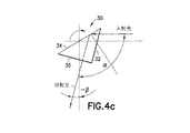
露光時間中のピッチ方向及びヨー方向の動きを補償するために、光学像スタビライザが使用される。本発明によれば、光学像スタビライザは、プリズムを二つの軸の周りで回転させる二つのアクチュエータを有する。図3に、プリズムの回転軸を示す。図3に示すように、プリズム30は、Z−X面に略平行な二つの三角面38、39と、X−Y面に略平行なベース面36と、Y−Z面に略平行な前面32と、ベース面36と45°の角をなす背面34とを有する。動きボケを減らすために、プリズムをZ軸及びY軸の周りで回転させることができる。
An optical image stabilizer is used to compensate for pitch and yaw motion during the exposure time. In accordance with the present invention, the optical image stabilizer has two actuators that rotate the prism about two axes. FIG. 3 shows the rotation axis of the prism. As shown in FIG. 3, the
公知のように、プリズムの前面32からX軸に平行な方向に沿って光がプリズムに入射したとき、その光線は背面34において全反射(TIR)によって反射される。図4aは、通常位置にあるプリズムを示す。光線は背面34に対して45°の角度で入射するため、イメージセンサの方へ、Z軸、すなわち結像システムの光軸方向にほぼ沿って反射される。図4bに示すように、プリズム30がY軸の周りを半時計回り方向に実質的に回転すると、反射された光線は正の角βで回転する。図4cに示すように、プリズム30がY軸の周りを時計回り方向に回転すると、反射された光線は実質的に負の角βで回転する。したがって、Y軸の周りでプリズムを傾転させることを、結像システムの無用なピッチ方向の動きを補償するために使用できる。
As is well known, when light enters the prism along the direction parallel to the X axis from the
電子駆動モジュールに動作可能に接続されたアクチュエータを用いて、このプリズムを傾転させることができる。電子駆動モジュールは動き検知デバイス(図10を参照)からの信号受信により、アクチュエータを動作させる。図5a〜図5cに、ピッチ方向の動きを補償する際、プリズムをY軸の周りで回転させるためにアクチュエータがどのように使用されるかの例を幾つか示す。図5aは、プリズム30をY軸の周りで回転させるために使用される屈曲アクチュエータ70を示す。図示のように、屈曲アクチュエータ70の一端72は結像システムに固定的に取り付けられ、屈曲アクチュエータ70の他端74はプリズム30に作用可能に接続される。動作の際、他端74の屈曲移動がプリズム30を傾転させる。図5bは、プリズム30をY軸の周りで回転させるために使用される屈曲アクチュエータ80を示す。図示のように、屈曲アクチュエータ80の両端82、84は結像システムに固定的に取り付けられ、屈曲アクチュエータ80の中央部86がプリズム30に対して作用可能に接続される。動作の際、中央部86の屈曲移動がプリズム30を傾転させる。なお、屈曲アクチュエータ80の中央部を固定的に取り付け、屈曲アクチュエータ80の一端または両端をプリズム30を傾転させるよう、プリズムに対して作用可能に接続することも可能であることに注意すべきである。
The prism can be tilted using an actuator operably connected to the electronic drive module. The electronic driving module operates the actuator by receiving a signal from the motion detection device (see FIG. 10). Figures 5a-5c show some examples of how the actuator is used to rotate the prism about the Y axis in compensating for pitch movement. FIG. 5a shows a bending
図5cは、プリズム30をY軸の周りで回転させるために使用される軸上アクチュエータ90を示す。図示のように、軸上アクチュエータ90の一端92は結像システムに固定的に取り付けられ、軸上アクチュエータ90の他端94はプリズム30に作用可能に接続される。動作の際、アクチュエータ90の収縮または膨張がプリズム30を傾転させる。
FIG. 5c shows an on-
図5dは、プリズム30をY軸の周りで回転させるために使用される、電磁ステッピングモータ、超音波ピエゾモータなどのような移動デバイス95を示す。
FIG. 5d shows a moving
ヨー方向の動き補償のために、プリズム30をZ軸の周りで回転させることも、アクチュエータにより行うことができる。図6aはプリズム30の平面図であり、プリズム30の様々な面に関係する回転軸を示す。図6b〜図6dに、ヨー方向の動きを補償する際、プリズムをZ軸の周りで回転させるためにアクチュエータがどのように使用されるかの例を幾つか示す。図6bは、プリズム30をZ軸の周りで回転させるために使用される屈曲アクチュエータ170を示す。図示のように、屈曲アクチュエータ170の一端172は結像システムに固定的に取り付けられ、屈曲アクチュエータ170の他端174はプリズム30に作用可能に接続される。動作の際、他端174の屈曲移動がプリズム30を回転させる。図6cは、プリズム30をZ軸の周りで回転させるために使用される屈曲アクチュエータ180を示す。図示のように、屈曲アクチュエータ180の両端182、184は結像システムに固定的に取り付けられ、屈曲アクチュエータ180の中央部186がプリズム30に対して作用可能に接続される。動作の際、中央部186の屈曲移動がプリズム30を回転させる。なお、屈曲アクチュエータ180の中央部を固定的に取り付け、屈曲アクチュエータ180の一端または両端をプリズム30を傾転させるよう、プリズムに対して作用可能に接続することも可能であることに注意すべきである。
The rotation of the
図6dは、プリズム30をZ軸の周りで回転させるために使用される軸上アクチュエータ190を示す。図示のように、軸上アクチュエータ190の一端192は結像システムに固定的に取り付けられ、軸上アクチュエータ190の他端194はプリズム30に作用可能に接続される。動作の際、アクチュエータ190の収縮または膨張がプリズム30を回転させる。
FIG. 6d shows an on-
図6eは、プリズム30をZ軸の周りで回転させるために使用される、電磁ステッピングモータ、超音波ピエゾモータなどのような移動デバイス195を示す。
FIG. 6e shows a moving
結像システムのプリズム30の回転及び傾転を、例えば、図7a〜図7cに示すようなジンバルシステムまたは図8〜図9bに示すようなジンバルジョイントの二つの屈曲アクチュエータを用いて行うことができる。
The rotation and tilting of the
図7a〜図7cは、結像システム10においてプリズムをY軸とZ軸の周りを回転させるために二つの屈曲アクチュエータがどのように使用されるかを示す。図7aは、本発明による、光学像安定化のためのジンバルプリズムシステム200を有する折り曲げ光学系の側面図である。プリズム30はジンバルシステム200内に隠れている。図7bは、ジンバルプリズムシステム200の詳細を示す図である。図7bに示すように、ジンバルプリズムシステム200は、Y軸回転用の第1の回転軸202及びZ軸回転用の第2の回転軸204において結像システムに取り付けられている。ジンバルプリズムシステム200は、プリズム(図示せず)をY軸の周りで傾転させる第1の屈曲アクチュエータ210と、プリズムをZ軸の周りで回転させる第2の屈曲アクチュエータ230とを有する。図示のように、ブラケット222は、屈曲アクチュエータ210の固定端212を取り付けるのに使用される。もう一つのブラケット224は、屈曲アクチュエータ210の他端214に対して作用可能に接続される。アクチュエータの一端214の屈曲移動によりプリズムをブラケット224を通じて回転軸202の周りで回転させるように、ブラケット224がプリズムシステム200にリンクされる。図7cに示すように、結像システム10のハウジングの一部は、屈曲アクチュエータ230の固定端232を固定的に取り付けるためのスロット252を有する。その屈曲アクチュエータの可動端234は、ブラケット244に対して作用可能に接続される。アクチュエータの一端234の屈曲移動によりプリズムを回転軸204の周りで回転させるように、ブラケット244がプリズムシステム200にリンクされる。
FIGS. 7a-7c illustrate how two bending actuators are used in the
図8は、ジンバルジョイント300の機構を示す。ジンバルジョイントは、カルダンサスペンション(cardanic suspension)としても知られている。図8に示すように、ジンバルジョイント300は、外側リングと、内側リングと、二つの交差した軸上のジョイントの二つのペアとを有する。プリズム30が内側リングに固定的に取り付けられると、ヨー方向とピッチ方向の様々な方向の補償のために、プリズムを移動させることができる。
FIG. 8 shows the mechanism of the
図9a及び図9bは、二つの軸の周りでジンバルジョイントを回転させる二つの屈曲アクチュエータを有するジンバルジョイントの例示的な実施態様を示す。図9a及び図9bに示すように、ジンバルジョイント300の外側リング360がZ軸の周りで回転可能なように、カルダンサスペンションは回転軸302でブラケット390に移動可能に取り付けられる。プリズム30を固定的に取り付けるために使用される内側リング350は、Y軸の周りで回転可能なように、回転軸304で外側リング360に移動可能に取り付けられる。第1の屈曲アクチュエータ310は固定端312と可動端314とを有する。固定端312は、ブラケット322により結像システム(図示せず)に固定的に取り付けられる。屈曲アクチュエータ310の可動端314はブラケット324に対して作用可能に接続される。そしてブラケット324は外側リング360にリンクされる。アクチュエータの一端314での屈曲移動それ自体が、ヨー方向の動き補償のために外側リング360を回転軸302の周りで回転させることができる。同様に、第2の屈曲アクチュエータ330は固定端332と可動端334とを有する。固定端332は、ブラケット342により結像システムに固定的に取り付けられる。屈曲アクチュエータ330の可動端334はブラケット344に対して作用可能に接続される。そしてブラケット344は内側リング350にリンクされる。アクチュエータの一端334での屈曲移動それ自体が、ピッチ方向の動き補償のために内側リング350を回転軸304の周りで回転させることができる。
Figures 9a and 9b show an exemplary embodiment of a gimbal joint having two bending actuators that rotate the gimbal joint about two axes. As shown in FIGS. 9a and 9b, the cardan suspension is movably attached to the
本発明によれば、屈曲アクチュエータを、モノモルフピエゾアクチュエータ、バイモルフピエゾアクチュエータ、多層ピエゾアクチュエータ、イオン導電性ポリマーアクチュエータ等とすることができることに留意されたい。さらに、アクチュエータが、アクチュエータを動作させるための駆動システムを必要とすることは公知である。図10は、代表的な駆動システムを示す図である。図示のように、アクチュエータは電子駆動モジュールに対して動作可能に接続される。その電子駆動モジュールは、アクチュエータがカメラの動きに応じて結像システムの構成部品を動かすように、カメラ動き検知器/信号プロセッサに接続される。駆動システムは本発明の一部をなすものではない。さらにまた、結像システムのレンズは、2個またはそれ以上のレンズ素子を有してもよく、アクチュエータを1個またはそれ以上のレンズ素子を動かすために使用してもよい。 It should be noted that, according to the present invention, the bending actuator can be a monomorph piezo actuator, a bimorph piezo actuator, a multilayer piezo actuator, an ion conductive polymer actuator, or the like. Furthermore, it is known that an actuator requires a drive system for operating the actuator. FIG. 10 is a diagram showing a typical drive system. As shown, the actuator is operably connected to the electronic drive module. The electronic drive module is connected to a camera motion detector / signal processor so that the actuator moves the components of the imaging system in response to camera motion. The drive system does not form part of the present invention. Furthermore, the lenses of the imaging system may have two or more lens elements, and an actuator may be used to move one or more lens elements.
さらに、プリズム30が像安定化の目的のために1または2軸に沿って回転するとき、他の構成部品も必要となる。例えば、結像システム用光学像スタビライザは、補償されるべき動きを判定する動き検知器、二つの回転軸に対するプリズムの現在位置を判定する少なくとも一つの位置検知器、プリズムの位置及びカメラの動きに基づいてカメラの動きを補償するために様々な方向の回転量を計算する信号プロセッサ、及び所望の量によりプリズムを回転させるよう、移動機構を動作させるために使用されるコントロールモジュールをも有する。図11に、そのような像スタビライザを示すブロック図を示す。動き検知器は、例えば、ジャイロスコープまたはアクセラレータを含んでもよい。
In addition, when
結像システムのレンズは、2個またはそれ以上のレンズ素子を有してもよく、アクチュエータを1個またはそれ以上のレンズ素子を動かすために使用してもよい。 The lens of the imaging system may have two or more lens elements, and an actuator may be used to move one or more lens elements.
光軸(または光路)を折り曲げるために使用されるプリズムは、図2〜4に示したようなプリズム30とは異なるものであってもよいことが当業者に理解されるであろう。例えば、プリズムの前面32(図3を参照)は、ベース面36に対して直交している必要はなく、背面34とベース面36とのなす角は、45°でなくてもよい。さらに、1以上の反射面を持つ様々な光学部品を、結像システムの光軸または光路を折り曲げる光折り曲げデバイスとして使用できる。また、図7〜図9bに示したジンバルプリズム及びジョイントは、単に説明を目的とするものである。二つのアクチュエータが、プリズムのような、光折り曲げデバイスを回転させるために使用される本発明を、様々なジンバル設計または構成を用いて達成することができる。
Those skilled in the art will appreciate that the prism used to fold the optical axis (or optical path) may be different from the
したがって、本発明を、その1以上の実施態様に関して説明してきたが、形式及びその詳細において、上記及び他の様々な変更、省略及び変形を、本発明の範囲から外れることなく行えることが当業者に理解されるであろう。 Thus, while the invention has been described with respect to one or more embodiments thereof, those skilled in the art can make various changes, omissions, and modifications in the form and details thereof without departing from the scope of the invention. Will be understood.
Claims (16)
像面に配置された画像形成媒体と、
前記画像形成媒体に像を投影し、光軸を規定するレンズモジュールと、
前記光軸を折り曲げるために前記レンズモジュールとの関係で配置される光路折り曲げデバイスと、
前記光路折り曲げデバイスと作用可能に接続され、前記結像システムの無用な動きに応じて前記画像形成媒体上の像をシフトするために前記光路折り曲げデバイスを移動させる移動機構と、
を有することを特徴とする結像システム。 An imaging system,
An image forming medium disposed on the image plane;
A lens module that projects an image on the image forming medium and defines an optical axis;
An optical path bending device arranged in relation to the lens module to fold the optical axis;
A moving mechanism operably connected to the optical path bending device and moving the optical path bending device to shift an image on the imaging medium in response to unnecessary movement of the imaging system;
An imaging system comprising:
前記反射面と作用可能に接続され、前記結像システムの無用な動きに応じて前記イメージセンサ上の像をシフトするために前記反射面を移動させる移動機構を有することを特徴とする光学像スタビライザモジュール。 An image sensor disposed on an image plane, at least one lens element that projects an image on the image sensor and defines an optical axis, and a reflective surface that is disposed in relation to the lens element to bend the optical axis An optical image stabilizer module for use in an imaging system comprising:
An optical image stabilizer comprising a moving mechanism that is operatively connected to the reflecting surface and moves the reflecting surface to shift an image on the image sensor in response to unnecessary movement of the imaging system. module.
前記プリズムに対して作用可能に接続され、前記プリズムを前記像面に略直交する第1の回転軸の周りで回転させる第1の移動デバイスと、
前記プリズムに対して作用可能に接続され、前記プリズムを前記像面及び前記プリズムの背面に略平行な第2の回転軸の周りで回転させる第2の移動デバイスと、
を有することを特徴とする請求項8に記載の光学像スタビライザモジュール。 The reflecting surface is a part of a prism, and the prism has a front surface, a base surface, and a back surface coupled to the front surface and the base surface, and the front surface is substantially orthogonal to the image surface. The base surface is substantially parallel to the image plane, and the back surface is used to bend the optical axis, and the moving mechanism comprises:
A first movement device operatively connected to the prism and rotating the prism about a first rotation axis substantially orthogonal to the image plane;
A second movement device operatively connected to the prism and rotating the prism about a second axis of rotation substantially parallel to the image plane and the back surface of the prism;
The optical image stabilizer module according to claim 8, comprising:
前記結像システムの無用な動きに基づいて前記第1及び第2のアクチュエータを動作させる駆動システムをさらに有することを特徴とする、請求項9に記載の光学像スタビライザモジュール。 The first moving device includes a first actuator, the second moving device includes a second actuator, and the optical image stabilizer module includes:
The optical image stabilizer module according to claim 9, further comprising a drive system that operates the first and second actuators based on unnecessary movement of the imaging system.
前記結像システムの無用な動きに基づいて前記各モータを動作させる駆動システムをさらに有することを特徴とする、請求項9に記載の光学像スタビライザモジュール。 The first moving device includes a motor, the second moving device includes a motor, and the optical image stabilizer module includes:
The optical image stabilizer module according to claim 9, further comprising a drive system that operates each of the motors based on useless movement of the imaging system.
前記プリズムの現在位置を検知する位置検知デバイスと、
前記位置検知デバイス及び動き検知器に動作可能に接続され、前記移動デバイスが前記結像システムの無用な動きを補償するために前記プリズムを動かせるように、前記プリズムの現在位置と前記結像システムの無用な動きに基づいて前記プリズムの移動量を決定するプロセッサモジュールと、
をさらに有することを特徴とする請求項8に記載の光学像スタビライザモジュール。 A drive system that operates the moving device in response to unwanted movement of the imaging system;
A position detection device for detecting the current position of the prism;
Operatively connected to the position sensing device and motion detector so that the moving device can move the prism to compensate for unwanted motion of the imaging system and the current position of the prism and the imaging system A processor module that determines the amount of movement of the prism based on unnecessary movement;
The optical image stabilizer module according to claim 8, further comprising:
前記結像システムは、前記結像システムの像面に配置されたイメージセンサと、
前記イメージセンサに像を投影し、光軸を規定する少なくとも一つのレンズ素子と、
前記光軸を折り曲げるために前記レンズ素子との関係で配置されるプリズムとを有し、該プリズムは前面と、ベース面と、該前面及びベース面と結合する背面とを有し、該前面は前記像面に対して略直交しており、該ベース面は前記像面に対して略平行であり、かつ該背面は反射により前記光軸を折り曲げるために使用され、前記方法は、
前記像面に対して略直交する第1の回転軸の周りで前記プリズムを回転させるステップと、
前記イメージセンサに投影された像をシフトするために、前記像面及び前記プリズムの背面に略平行な第2の回転軸の周りで前記プリズムを回転させるステップと、
を含むことを特徴とする像移動方法。 An image transfer method used in an imaging system to compensate for unwanted movement of the imaging system, comprising:
The imaging system includes an image sensor disposed on an image plane of the imaging system;
At least one lens element that projects an image on the image sensor and defines an optical axis;
A prism disposed in relation to the lens element to bend the optical axis, the prism having a front surface, a base surface, and a back surface coupled to the front surface and the base surface, The base plane is substantially parallel to the image plane, and the back side is used to fold the optical axis by reflection, the method comprising:
Rotating the prism around a first axis of rotation substantially orthogonal to the image plane;
Rotating the prism about a second axis of rotation substantially parallel to the image plane and the back of the prism to shift the image projected onto the image sensor;
An image moving method characterized by comprising:
第2の移動デバイスを前記プリズムに対して作用可能に接続するステップと、
前記第1の回転軸の周りで前記プリズムが回転するように前記第1の移動デバイスを動作させるステップと、
前記第2の回転軸の周りで前記プリズムが回転するように前記第2の移動デバイスを動作させ、該動作が前記結像システムの無用な動きに応じているステップと、
をさらに含むことを特徴とする請求項15に記載の像移動方法。 Operably connecting a first moving device to the prism;
Operably connecting a second moving device to the prism;
Operating the first moving device to rotate the prism about the first axis of rotation;
Operating the second moving device to rotate the prism about the second axis of rotation, the operation being in response to unwanted movement of the imaging system;
The image moving method according to claim 15, further comprising:
Applications Claiming Priority (1)
| Application Number | Priority Date | Filing Date | Title |
|---|---|---|---|
| PCT/IB2006/000219 WO2007091112A1 (en) | 2006-02-06 | 2006-02-06 | Optical image stabilizer using gimballed prism |
Publications (1)
| Publication Number | Publication Date |
|---|---|
| JP2009526257A true JP2009526257A (en) | 2009-07-16 |
Family
ID=38344891
Family Applications (1)
| Application Number | Title | Priority Date | Filing Date |
|---|---|---|---|
| JP2008553837A Pending JP2009526257A (en) | 2006-02-06 | 2006-02-06 | Optical image stabilizer using gimbal prism |
Country Status (5)
| Country | Link |
|---|---|
| US (1) | US20090122406A1 (en) |
| EP (1) | EP1984774A4 (en) |
| JP (1) | JP2009526257A (en) |
| CN (1) | CN101401023A (en) |
| WO (1) | WO2007091112A1 (en) |
Cited By (24)
| Publication number | Priority date | Publication date | Assignee | Title |
|---|---|---|---|---|
| KR20100089544A (en) * | 2009-02-04 | 2010-08-12 | 삼성전자주식회사 | Zoom lens system and photographic device capable of image stabilizing |
| KR20140014787A (en) * | 2012-07-26 | 2014-02-06 | 엘지이노텍 주식회사 | Camera module |
| JP2015011353A (en) * | 2013-07-01 | 2015-01-19 | 台湾東電化股▲ふん▼有限公司 | Optical anti-shake mechanism with switchable light path |
| JP2015092285A (en) * | 2015-02-03 | 2015-05-14 | 株式会社ファイブ・ディー | Vibration-proof device for folded zoom camera module |
| KR20170128612A (en) * | 2015-09-06 | 2017-11-22 | 코어포토닉스 리미티드 | Automatic focus and optical image stabilization by roll compensation of compact folding camera |
| KR20190092459A (en) * | 2016-12-28 | 2019-08-07 | 코어포토닉스 리미티드 | Folding camera structure with extended light-folding-element scanning range |
| WO2019156933A1 (en) * | 2018-02-07 | 2019-08-15 | Apple Inc. | Folded camera |
| CN110398872A (en) * | 2018-04-25 | 2019-11-01 | 华为技术有限公司 | A lens module and a camera |
| KR20190137036A (en) * | 2019-11-27 | 2019-12-10 | 엘지이노텍 주식회사 | Camera module |
| JP2020190651A (en) * | 2019-05-22 | 2020-11-26 | 新シコー科技株式会社 | Optical element drive device, camera device and electronic apparatus |
| JP2020190658A (en) * | 2019-05-22 | 2020-11-26 | 新シコー科技株式会社 | Optical element drive device, camera device, and electronic apparatus |
| JP2020190655A (en) * | 2019-05-22 | 2020-11-26 | 新シコー科技株式会社 | Optical element drive device, camera device, and electronic device |
| JP2020190650A (en) * | 2019-05-22 | 2020-11-26 | 新シコー科技株式会社 | Optical element drive device, camera device, and electronic device |
| CN112394471A (en) * | 2019-07-31 | 2021-02-23 | 新思考电机有限公司 | Optical element driving device, camera device, and electronic apparatus |
| US10969652B2 (en) | 2018-01-10 | 2021-04-06 | Apple Inc. | Camera with folded optics having moveable lens |
| JPWO2021106755A1 (en) * | 2019-11-27 | 2021-06-03 | ||
| WO2021158033A1 (en) * | 2020-02-06 | 2021-08-12 | 엘지이노텍 주식회사 | Prism actuator |
| US11092773B2 (en) | 2018-01-26 | 2021-08-17 | Apple Inc. | Folded camera with actuator for moving optics |
| KR20210115421A (en) * | 2020-03-13 | 2021-09-27 | 삼성전기주식회사 | Camera Module |
| WO2021235834A1 (en) * | 2020-05-19 | 2021-11-25 | 엘지이노텍 주식회사 | Camera actuator and camera device comprising same |
| US11314147B1 (en) | 2018-05-31 | 2022-04-26 | Apple Inc. | Folded camera with actuator for moving optics |
| JP2022531015A (en) * | 2019-05-05 | 2022-07-05 | 華為技術有限公司 | Compact camera modules, terminal devices, imaging methods, and imaging devices |
| JP7510794B2 (en) | 2020-06-22 | 2024-07-04 | ニデックインスツルメンツ株式会社 | Optical Unit |
| JP7616879B2 (en) | 2020-12-17 | 2025-01-17 | ニデックインスツルメンツ株式会社 | Optical unit with shake correction function |
Families Citing this family (86)
| Publication number | Priority date | Publication date | Assignee | Title |
|---|---|---|---|---|
| US8089694B2 (en) * | 2007-08-24 | 2012-01-03 | Sony Ericsson Mobile Communications Ab | Optical device stabilizer |
| KR101509256B1 (en) * | 2008-11-28 | 2015-04-16 | 삼성전자주식회사 | Optical image stabilizer for camera lens assembly |
| US20100226010A1 (en) * | 2009-03-04 | 2010-09-09 | Kai Cheong Kwan | Anti-Shaking Optical Element For Optical Imaging Systems |
| WO2010108319A1 (en) * | 2009-03-25 | 2010-09-30 | Hong Kong Applied Science & Technology Research Institute Co., Ltd | Optical imaging system with an anti-shaking optical element |
| TWM376769U (en) * | 2009-08-28 | 2010-03-21 | Altek Corp | Prism type lens structure |
| US8866919B2 (en) | 2009-11-06 | 2014-10-21 | Samsung Techwin Co., Ltd. | Shake correction module, camera module comprising the same, and method of manufacturing the camera module |
| CN102243349A (en) * | 2010-05-10 | 2011-11-16 | 鸿富锦精密工业(深圳)有限公司 | Refraction lens, lens module and imaging device with the lens module |
| US9172856B2 (en) | 2011-03-29 | 2015-10-27 | Microsoft Technology Licensing, Llc | Folded imaging path camera |
| US9538152B2 (en) | 2012-11-28 | 2017-01-03 | Corephotonics Ltd. | High resolution thin multi-aperture imaging systems |
| CN109194849B (en) | 2013-06-13 | 2021-01-15 | 核心光电有限公司 | Dual Aperture Zoom Digital Camera |
| EP4379443A3 (en) | 2013-07-04 | 2024-09-04 | Corephotonics Ltd. | Miniature telephoto lens assembly |
| US9571731B2 (en) | 2013-08-01 | 2017-02-14 | Corephotonics Ltd. | Thin multi-aperture imaging system with auto-focus and methods for using same |
| CN103676405A (en) * | 2013-12-02 | 2014-03-26 | 宇龙计算机通信科技(深圳)有限公司 | Optical imaging device, optical system and mobile terminal |
| US9338357B2 (en) * | 2014-01-30 | 2016-05-10 | Hoya Corporation | Imaging apparatus |
| FR3019316B1 (en) | 2014-03-28 | 2017-08-11 | Sagem Defense Securite | OPTRONIC VEHICLE SYSTEM WITH VARIABLE OPTIC FIELD |
| US9392188B2 (en) | 2014-08-10 | 2016-07-12 | Corephotonics Ltd. | Zoom dual-aperture camera with folded lens |
| CN112433331B (en) | 2015-01-03 | 2022-07-08 | 核心光电有限公司 | Miniature telephoto lens module and camera using the same |
| KR101914894B1 (en) | 2015-04-02 | 2018-11-02 | 코어포토닉스 리미티드 | Dual voice coil motor structure of dual optical module camera |
| CN112305833A (en) | 2015-04-16 | 2021-02-02 | 核心光电有限公司 | Autofocus and optical image stabilization in compact folding cameras |
| US9857584B2 (en) | 2015-04-17 | 2018-01-02 | Light Labs Inc. | Camera device methods, apparatus and components |
| KR102007379B1 (en) | 2015-05-28 | 2019-08-05 | 코어포토닉스 리미티드 | Bi-directional stiffness for optical image stabilization and auto-focus in a dual-aperture digital camera |
| WO2016207754A1 (en) * | 2015-06-24 | 2016-12-29 | Corephotonics Ltd. | Low profile tri-axis actuator for folded lens camera |
| KR102143309B1 (en) | 2015-08-13 | 2020-08-11 | 코어포토닉스 리미티드 | Dual aperture zoom camera with video support and switching/non-switching dynamic control |
| DE102015215837A1 (en) | 2015-08-19 | 2017-02-23 | Fraunhofer-Gesellschaft zur Förderung der angewandten Forschung e.V. | Multi-aperture imaging apparatus, method of making same and imaging system |
| DE102015215840B4 (en) | 2015-08-19 | 2017-03-23 | Fraunhofer-Gesellschaft zur Förderung der angewandten Forschung e.V. | A multi-aperture imaging apparatus, imaging system, and method of providing a multi-aperture imaging apparatus |
| DE102015215845B4 (en) | 2015-08-19 | 2017-06-22 | Fraunhofer-Gesellschaft zur Förderung der angewandten Forschung e.V. | Multi-aperture imaging device with channel-specific adjustability |
| DE102015215836B4 (en) * | 2015-08-19 | 2017-05-18 | Fraunhofer-Gesellschaft zur Förderung der angewandten Forschung e.V. | Multiaperture imaging device with a reflective facet beam deflection device |
| CN109946832B (en) | 2015-12-29 | 2021-01-19 | 核心光电有限公司 | Dual aperture zoom digital camera with automatically adjustable telephoto field of view |
| KR102063411B1 (en) | 2016-05-30 | 2020-01-07 | 코어포토닉스 리미티드 | Rotational ball-guided voice coil motor |
| EP4270978A3 (en) | 2016-06-19 | 2024-02-14 | Corephotonics Ltd. | Frame synchronization in a dual-aperture camera system |
| KR102226315B1 (en) | 2016-07-07 | 2021-03-12 | 코어포토닉스 리미티드 | Linear ball guided voice coil motor for folded optic |
| US10706518B2 (en) | 2016-07-07 | 2020-07-07 | Corephotonics Ltd. | Dual camera system with improved video smooth transition by image blending |
| US10516773B2 (en) * | 2016-10-13 | 2019-12-24 | Samsung Electro-Mechanics Co., Ltd. | Camera module and portable electronic device including the same |
| KR102365926B1 (en) | 2017-01-12 | 2022-02-23 | 코어포토닉스 리미티드 | Compact folded camera |
| US10678062B2 (en) | 2017-02-08 | 2020-06-09 | Samsung Electro-Mechanics Co., Ltd. | Reflecting module for optical image stabilization (OIS) and camera module including the same |
| KR102046472B1 (en) | 2017-02-15 | 2019-11-19 | 삼성전기주식회사 | Mirror Module for OIS and Camera module including the same |
| KR20220013000A (en) | 2017-02-23 | 2022-02-04 | 코어포토닉스 리미티드 | Folded camera lens designs |
| KR20250028499A (en) * | 2017-03-15 | 2025-02-28 | 코어포토닉스 리미티드 | Camera with panoramic scanning range |
| KR101892857B1 (en) * | 2017-06-12 | 2018-08-28 | 삼성전기주식회사 | Mirror Module for OIS and Camera module including the same |
| KR102473411B1 (en) * | 2017-07-03 | 2022-12-02 | 삼성전기주식회사 | Camera module |
| WO2019048904A1 (en) | 2017-09-06 | 2019-03-14 | Corephotonics Ltd. | Combined stereoscopic and phase detection depth mapping in a dual aperture camera |
| US10951834B2 (en) | 2017-10-03 | 2021-03-16 | Corephotonics Ltd. | Synthetically enlarged camera aperture |
| US11333955B2 (en) | 2017-11-23 | 2022-05-17 | Corephotonics Ltd. | Compact folded camera structure |
| CN110352371B (en) | 2018-02-05 | 2022-05-13 | 核心光电有限公司 | Folding camera device capable of reducing height allowance |
| JP7007574B2 (en) * | 2018-02-06 | 2022-02-10 | ミツミ電機株式会社 | Camera actuators, camera modules, and camera-mounted devices |
| CN113467031B (en) | 2018-02-12 | 2023-07-14 | 核心光电有限公司 | Folded camera with optical image stabilization, digital camera and method |
| US20190260943A1 (en) * | 2018-02-22 | 2019-08-22 | Perspective Components, Inc. | Methods for dynamic camera position adjustment |
| JP6452875B1 (en) * | 2018-03-29 | 2019-01-16 | 株式会社日立製作所 | Moving body imaging system and moving body imaging method |
| US10694168B2 (en) | 2018-04-22 | 2020-06-23 | Corephotonics Ltd. | System and method for mitigating or preventing eye damage from structured light IR/NIR projector systems |
| EP4303653A1 (en) | 2018-04-23 | 2024-01-10 | Corephotonics Ltd. | An optical-path folding-element with an extended two degree of freedom rotation range |
| JP7028983B2 (en) | 2018-08-04 | 2022-03-02 | コアフォトニクス リミテッド | Switchable continuous display information system on the camera |
| US11635596B2 (en) | 2018-08-22 | 2023-04-25 | Corephotonics Ltd. | Two-state zoom folded camera |
| US11336830B2 (en) * | 2019-01-03 | 2022-05-17 | Corephotonics Ltd. | Multi-aperture cameras with at least one two state zoom camera |
| US11287081B2 (en) | 2019-01-07 | 2022-03-29 | Corephotonics Ltd. | Rotation mechanism with sliding joint |
| KR102494006B1 (en) | 2019-03-09 | 2023-01-30 | 코어포토닉스 리미티드 | System and method for dynamic stereoscopic calibration |
| JP6613005B1 (en) * | 2019-04-16 | 2019-11-27 | エーエーシーアコースティックテクノロジーズ(シンセン)カンパニーリミテッドAAC Acoustic Technologies(Shenzhen)Co.,Ltd | Anti-vibration mechanism for bending imaging apparatus, camera, and portable electronic device |
| US11256061B2 (en) | 2019-05-22 | 2022-02-22 | New Shicoh Motor Co., Ltd | Optical element driving device, camera device and electronic apparatus |
| WO2020243852A2 (en) * | 2019-06-01 | 2020-12-10 | 瑞声光学解决方案私人有限公司 | Camera lens module |
| CN112394536B (en) * | 2019-07-31 | 2022-04-29 | 华为技术有限公司 | Optical anti-shake device and control method |
| US11368631B1 (en) | 2019-07-31 | 2022-06-21 | Corephotonics Ltd. | System and method for creating background blur in camera panning or motion |
| US11867925B2 (en) * | 2019-08-30 | 2024-01-09 | Tdk Taiwan Corp. | Driving mechanism for optical element |
| US11659135B2 (en) | 2019-10-30 | 2023-05-23 | Corephotonics Ltd. | Slow or fast motion video using depth information |
| CN213182169U (en) | 2019-11-01 | 2021-05-11 | 台湾东电化股份有限公司 | Optical element driving mechanism |
| EP4045959B1 (en) * | 2019-12-03 | 2025-02-05 | Corephotonics Ltd. | Actuators for providing an extended two-degree of freedom rotation range |
| US11949976B2 (en) | 2019-12-09 | 2024-04-02 | Corephotonics Ltd. | Systems and methods for obtaining a smart panoramic image |
| CN114641983A (en) | 2019-12-09 | 2022-06-17 | 核心光电有限公司 | System and method for obtaining intelligent panoramic image |
| KR20220053023A (en) | 2020-02-22 | 2022-04-28 | 코어포토닉스 리미티드 | Split screen function for macro shooting |
| KR102732454B1 (en) | 2020-04-26 | 2024-11-20 | 코어포토닉스 리미티드 | Temperature control for hall bar sensor correction |
| KR20210132986A (en) * | 2020-04-28 | 2021-11-05 | 엘지이노텍 주식회사 | Camera actuator and camera module including the same |
| CN111541833A (en) * | 2020-04-29 | 2020-08-14 | 维沃移动通信有限公司 | Camera module, electronic equipment and camera shooting method |
| US11832018B2 (en) | 2020-05-17 | 2023-11-28 | Corephotonics Ltd. | Image stitching in the presence of a full field of view reference image |
| EP3966631B1 (en) | 2020-05-30 | 2023-01-25 | Corephotonics Ltd. | Systems and methods for obtaining a super macro image |
| CN213581563U (en) * | 2020-06-30 | 2021-06-29 | 诚瑞光学(常州)股份有限公司 | Optical device and electronic apparatus |
| US11637977B2 (en) | 2020-07-15 | 2023-04-25 | Corephotonics Ltd. | Image sensors and sensing methods to obtain time-of-flight and phase detection information |
| EP4528372A2 (en) | 2020-07-15 | 2025-03-26 | Corephotonics Ltd. | Point of view aberrations correction in a scanning folded camera |
| KR20230035127A (en) * | 2020-07-17 | 2023-03-10 | 후아웨이 테크놀러지 컴퍼니 리미티드 | Cameras for portable electronic devices with optical image stabilization |
| CN118433505A (en) | 2020-07-31 | 2024-08-02 | 核心光电有限公司 | Camera with camera body |
| KR20250016472A (en) | 2020-08-12 | 2025-02-03 | 코어포토닉스 리미티드 | Optical image stabilization in a scanning folded camera |
| CN112255818B (en) * | 2020-11-03 | 2022-06-03 | 广州立景创新科技有限公司 | Imaging correction unit and imaging module |
| TWI764353B (en) * | 2020-11-03 | 2022-05-11 | 大陸商廣州立景創新科技有限公司 | Imaging correction unit and imaging module |
| KR20220126781A (en) * | 2020-11-10 | 2022-09-16 | 베이징 시아오미 모바일 소프트웨어 컴퍼니 리미티드 | Optical Imaging Systems, How to Perform Optical Image Stabilization |
| EP4085607A4 (en) | 2020-12-26 | 2023-09-20 | Corephotonics Ltd. | VIDEO SUPPORT IN A MULTI-APERTURE MOBILE CAMERA HAVING A SCANNING ZOOM CAMERA |
| CN115868168A (en) | 2021-03-11 | 2023-03-28 | 核心光电有限公司 | System for pop-up camera |
| CN115202130A (en) * | 2021-04-09 | 2022-10-18 | 宁波舜宇光电信息有限公司 | Periscopic camera module |
| WO2022259154A2 (en) | 2021-06-08 | 2022-12-15 | Corephotonics Ltd. | Systems and cameras for tilting a focal plane of a super-macro image |
| WO2023111711A1 (en) * | 2021-12-14 | 2023-06-22 | Corephotonics Ltd. | Large-aperture compact scanning tele cameras |
Citations (3)
| Publication number | Priority date | Publication date | Assignee | Title |
|---|---|---|---|---|
| JPH04211230A (en) * | 1989-10-20 | 1992-08-03 | Fuji Photo Film Co Ltd | Compensator for camera shake by hand |
| JP2000010139A (en) * | 1998-06-18 | 2000-01-14 | Asahi Optical Co Ltd | Image shake correcting camera and image shake correcting method for camera |
| JP2004219930A (en) * | 2003-01-17 | 2004-08-05 | Minolta Co Ltd | Camera with camera-shake correction function |
Family Cites Families (10)
| Publication number | Priority date | Publication date | Assignee | Title |
|---|---|---|---|---|
| US1235175A (en) * | 1916-06-13 | 1917-07-31 | Adolph Winkler | Skirt-marker. |
| US3475074A (en) * | 1967-06-01 | 1969-10-28 | Optical Res & Dev Corp | Accidental-motion compensation with collimated light |
| US3915550A (en) * | 1974-10-02 | 1975-10-28 | Optigon Res & Dev Corp | Stabilized binocular |
| US5333076A (en) * | 1988-01-21 | 1994-07-26 | Fairchild Weston Systems, Inc. | Stabilized imaging system |
| DE3829708A1 (en) * | 1988-09-01 | 1990-03-15 | Zeiss Carl Fa | SWITCHABLE ANGLE MIRROR FOR PERISCOPE |
| JP3364945B2 (en) * | 1992-01-31 | 2003-01-08 | ソニー株式会社 | Camera shake correction device and camera shake correction method |
| JP4042170B2 (en) * | 1996-11-13 | 2008-02-06 | 株式会社ニコン | Anti-vibration telescope |
| US6144478A (en) * | 1998-12-11 | 2000-11-07 | Xerox Corporation | Flexible arm piezoelectric lens mover |
| JP3896988B2 (en) * | 2003-05-12 | 2007-03-22 | コニカミノルタフォトイメージング株式会社 | Imaging lens device |
| US20050057659A1 (en) * | 2003-09-16 | 2005-03-17 | Takami Hasegawa | Camera image shake correcting device |
-
2006
- 2006-02-06 JP JP2008553837A patent/JP2009526257A/en active Pending
- 2006-02-06 CN CNA2006800539025A patent/CN101401023A/en active Pending
- 2006-02-06 EP EP06710324A patent/EP1984774A4/en not_active Withdrawn
- 2006-02-06 US US12/223,506 patent/US20090122406A1/en not_active Abandoned
- 2006-02-06 WO PCT/IB2006/000219 patent/WO2007091112A1/en active Application Filing
Patent Citations (3)
| Publication number | Priority date | Publication date | Assignee | Title |
|---|---|---|---|---|
| JPH04211230A (en) * | 1989-10-20 | 1992-08-03 | Fuji Photo Film Co Ltd | Compensator for camera shake by hand |
| JP2000010139A (en) * | 1998-06-18 | 2000-01-14 | Asahi Optical Co Ltd | Image shake correcting camera and image shake correcting method for camera |
| JP2004219930A (en) * | 2003-01-17 | 2004-08-05 | Minolta Co Ltd | Camera with camera-shake correction function |
Cited By (50)
| Publication number | Priority date | Publication date | Assignee | Title |
|---|---|---|---|---|
| KR101661325B1 (en) | 2009-02-04 | 2016-09-29 | 삼성전자주식회사 | Zoom lens system and photographic device capable of image stabilizing |
| KR20100089544A (en) * | 2009-02-04 | 2010-08-12 | 삼성전자주식회사 | Zoom lens system and photographic device capable of image stabilizing |
| KR102051501B1 (en) * | 2012-07-26 | 2019-12-03 | 엘지이노텍 주식회사 | Camera module |
| KR20140014787A (en) * | 2012-07-26 | 2014-02-06 | 엘지이노텍 주식회사 | Camera module |
| JP2015011353A (en) * | 2013-07-01 | 2015-01-19 | 台湾東電化股▲ふん▼有限公司 | Optical anti-shake mechanism with switchable light path |
| US9258486B2 (en) | 2013-07-01 | 2016-02-09 | Tdk Taiwan Corp. | Optical anti-shake apparatus with switchable light path |
| JP2015092285A (en) * | 2015-02-03 | 2015-05-14 | 株式会社ファイブ・ディー | Vibration-proof device for folded zoom camera module |
| KR101993077B1 (en) * | 2015-09-06 | 2019-06-25 | 코어포토닉스 리미티드 | Automatic focus and optical image stabilization by roll compensation of compact folding camera |
| KR20200096677A (en) * | 2015-09-06 | 2020-08-12 | 코어포토닉스 리미티드 | Auto focus and optical image stabilization with roll compensation in a compact folded camera |
| KR20170128612A (en) * | 2015-09-06 | 2017-11-22 | 코어포토닉스 리미티드 | Automatic focus and optical image stabilization by roll compensation of compact folding camera |
| KR102225727B1 (en) * | 2015-09-06 | 2021-03-10 | 코어포토닉스 리미티드 | Auto focus and optical image stabilization with roll compensation in a compact folded camera |
| KR102143730B1 (en) * | 2015-09-06 | 2020-08-12 | 코어포토닉스 리미티드 | Auto focus and optical image stabilization with roll compensation in a compact folded camera |
| KR20190072690A (en) * | 2015-09-06 | 2019-06-25 | 코어포토닉스 리미티드 | Auto focus and optical image stabilization with roll compensation in a compact folded camera |
| KR102269547B1 (en) | 2016-12-28 | 2021-06-25 | 코어포토닉스 리미티드 | Folded camera structure with extended light-folding-element scanning range |
| KR20190092459A (en) * | 2016-12-28 | 2019-08-07 | 코어포토닉스 리미티드 | Folding camera structure with extended light-folding-element scanning range |
| US10969652B2 (en) | 2018-01-10 | 2021-04-06 | Apple Inc. | Camera with folded optics having moveable lens |
| US11934090B2 (en) | 2018-01-10 | 2024-03-19 | Apple Inc. | Camera with folded optics having moveable lens |
| US11092773B2 (en) | 2018-01-26 | 2021-08-17 | Apple Inc. | Folded camera with actuator for moving optics |
| US11726295B2 (en) | 2018-01-26 | 2023-08-15 | Apple Inc. | Folded camera with actuator for moving optics |
| US11536936B2 (en) | 2018-02-07 | 2022-12-27 | Apple Inc. | Folded camera |
| US11061213B2 (en) | 2018-02-07 | 2021-07-13 | Apple Inc. | Folded camera |
| WO2019156933A1 (en) * | 2018-02-07 | 2019-08-15 | Apple Inc. | Folded camera |
| US11754821B2 (en) | 2018-02-07 | 2023-09-12 | Apple Inc. | Folded camera |
| US12047663B2 (en) | 2018-04-25 | 2024-07-23 | Huawei Technologies Co., Ltd. | Lens module and camera |
| CN110398872A (en) * | 2018-04-25 | 2019-11-01 | 华为技术有限公司 | A lens module and a camera |
| US11314147B1 (en) | 2018-05-31 | 2022-04-26 | Apple Inc. | Folded camera with actuator for moving optics |
| US11971651B2 (en) | 2018-05-31 | 2024-04-30 | Apple Inc. | Folded camera with actuator for moving optics |
| US11796893B2 (en) | 2019-05-05 | 2023-10-24 | Huawei Technologies Co., Ltd. | Compact camera module and terminal device |
| JP7313478B2 (en) | 2019-05-05 | 2023-07-24 | 華為技術有限公司 | Compact camera module, terminal device, imaging method, and imaging apparatus |
| JP2022531015A (en) * | 2019-05-05 | 2022-07-05 | 華為技術有限公司 | Compact camera modules, terminal devices, imaging methods, and imaging devices |
| JP2020190658A (en) * | 2019-05-22 | 2020-11-26 | 新シコー科技株式会社 | Optical element drive device, camera device, and electronic apparatus |
| JP2020190650A (en) * | 2019-05-22 | 2020-11-26 | 新シコー科技株式会社 | Optical element drive device, camera device, and electronic device |
| JP2020190651A (en) * | 2019-05-22 | 2020-11-26 | 新シコー科技株式会社 | Optical element drive device, camera device and electronic apparatus |
| JP2020190655A (en) * | 2019-05-22 | 2020-11-26 | 新シコー科技株式会社 | Optical element drive device, camera device, and electronic device |
| CN112394471A (en) * | 2019-07-31 | 2021-02-23 | 新思考电机有限公司 | Optical element driving device, camera device, and electronic apparatus |
| JPWO2021106755A1 (en) * | 2019-11-27 | 2021-06-03 | ||
| WO2021106755A1 (en) * | 2019-11-27 | 2021-06-03 | アルプスアルパイン株式会社 | Reflector driving device |
| JP7266708B2 (en) | 2019-11-27 | 2023-04-28 | アルプスアルパイン株式会社 | Reflector drive |
| CN114730120A (en) * | 2019-11-27 | 2022-07-08 | 阿尔卑斯阿尔派株式会社 | reflector drive |
| KR20190137036A (en) * | 2019-11-27 | 2019-12-10 | 엘지이노텍 주식회사 | Camera module |
| KR102161254B1 (en) * | 2019-11-27 | 2020-10-05 | 엘지이노텍 주식회사 | Camera module |
| US12216258B2 (en) | 2020-02-06 | 2025-02-04 | Lg Innotek Co., Ltd. | Prism actuator |
| WO2021158033A1 (en) * | 2020-02-06 | 2021-08-12 | 엘지이노텍 주식회사 | Prism actuator |
| KR102345114B1 (en) * | 2020-03-13 | 2021-12-30 | 삼성전기주식회사 | Camera Module |
| KR20210115421A (en) * | 2020-03-13 | 2021-09-27 | 삼성전기주식회사 | Camera Module |
| US11609404B2 (en) | 2020-03-13 | 2023-03-21 | Samsung Electro-Mechanics Co., Ltd. | Camera module |
| WO2021235834A1 (en) * | 2020-05-19 | 2021-11-25 | 엘지이노텍 주식회사 | Camera actuator and camera device comprising same |
| US12108153B2 (en) | 2020-05-19 | 2024-10-01 | Lg Innotek Co., Ltd. | Camera actuator and camera device comprising same |
| JP7510794B2 (en) | 2020-06-22 | 2024-07-04 | ニデックインスツルメンツ株式会社 | Optical Unit |
| JP7616879B2 (en) | 2020-12-17 | 2025-01-17 | ニデックインスツルメンツ株式会社 | Optical unit with shake correction function |
Also Published As
| Publication number | Publication date |
|---|---|
| CN101401023A (en) | 2009-04-01 |
| US20090122406A1 (en) | 2009-05-14 |
| EP1984774A1 (en) | 2008-10-29 |
| WO2007091112A1 (en) | 2007-08-16 |
| EP1984774A4 (en) | 2010-11-24 |
Similar Documents
| Publication | Publication Date | Title |
|---|---|---|
| JP2009526257A (en) | Optical image stabilizer using gimbal prism | |
| JP3861815B2 (en) | Camera with image stabilization function | |
| JP5787510B2 (en) | Bending zoom camera module | |
| CN111787190B (en) | Periscopic camera module and multi-camera module | |
| US20190285907A1 (en) | Image acquisition device | |
| JP2015092285A (en) | Vibration-proof device for folded zoom camera module | |
| TWI630423B (en) | Apparatus and method for compensating hand blur | |
| US6486910B1 (en) | Photographing apparatus having the image blur preventing function | |
| US20110158617A1 (en) | Device for providing stabilized images in a hand held camera | |
| JP2010518443A (en) | A device that provides a stable image with a handheld camera | |
| US11747642B2 (en) | Optical unit | |
| JP4973219B2 (en) | Optical equipment | |
| JP2003207715A (en) | Variable power optical system and optical equipment using it | |
| US11002981B2 (en) | Anti-vibration device and binocle | |
| JP5458521B2 (en) | Lens barrel, lens barrel adjustment method, optical device, and optical device adjustment method | |
| JPH0682888A (en) | Vibration proof device with variable apex angle prism | |
| JPH07301839A (en) | Camera shake correcting device | |
| JPH06148730A (en) | Camera shaking correction device | |
| KR100877070B1 (en) | A shake compensation apparatus of an image pickup apparatus | |
| JP7410559B2 (en) | Anti-vibration optical device | |
| EP3750005B1 (en) | Lens arrangement | |
| JPH05134286A (en) | Variable apex angle prism device | |
| JPH02183216A (en) | Image stabilization device | |
| JPH10104678A (en) | Apex angle variable prism and shake correction device using it | |
| JP2000227613A (en) | Camera shake correcting device |
Legal Events
| Date | Code | Title | Description |
|---|---|---|---|
| A977 | Report on retrieval |
Free format text: JAPANESE INTERMEDIATE CODE: A971007 Effective date: 20100210 |
|
| A131 | Notification of reasons for refusal |
Free format text: JAPANESE INTERMEDIATE CODE: A131 Effective date: 20100223 |
|
| A02 | Decision of refusal |
Free format text: JAPANESE INTERMEDIATE CODE: A02 Effective date: 20110405 |