JP2009272800A - Quality measurement system, reception device, quality measuring method, and program - Google Patents
Quality measurement system, reception device, quality measuring method, and program Download PDFInfo
- Publication number
- JP2009272800A JP2009272800A JP2008120342A JP2008120342A JP2009272800A JP 2009272800 A JP2009272800 A JP 2009272800A JP 2008120342 A JP2008120342 A JP 2008120342A JP 2008120342 A JP2008120342 A JP 2008120342A JP 2009272800 A JP2009272800 A JP 2009272800A
- Authority
- JP
- Japan
- Prior art keywords
- quality
- delay data
- packet
- test
- quality measurement
- Prior art date
- Legal status (The legal status is an assumption and is not a legal conclusion. Google has not performed a legal analysis and makes no representation as to the accuracy of the status listed.)
- Ceased
Links
Images


Landscapes
- Data Exchanges In Wide-Area Networks (AREA)
- Maintenance And Management Of Digital Transmission (AREA)
- Monitoring And Testing Of Transmission In General (AREA)
- Mobile Radio Communication Systems (AREA)
Abstract
【課題】無線区間を含むネットワークにおいて、精度の高い通信品質計測を可能にする品質計測システム、受信装置、品質計測方法及びプログラムを提供する。
【解決手段】パケットが無線フレームに分割されて伝送される無線区間を有する通信ネットワークの通信品質を計測する品質計測システムは、サイズの異なるテストパケットを生成するパケット生成部と、無線区間経由でパケットが伝送される受信装置2宛てにサイズの異なるテストパケットを混在させて送信する送信部と、を有する送信装置1と、送信装置1から送信されたテストパケットを受信し、該受信データを記録する受信部と、テストパケットのサイズ別の前記遅延データから線形近似した傾き及びテストパケットのサイズ別の前記遅延データの揺らぎに基づいて通信品質を計測する品質計測部と、を有する受信装置2と、を備える。
【選択図】図1A quality measurement system, a receiving device, a quality measurement method, and a program that enable highly accurate communication quality measurement in a network including a wireless section.
A quality measurement system for measuring communication quality of a communication network having a wireless section in which a packet is transmitted by being divided into wireless frames includes a packet generator for generating test packets of different sizes, and a packet via the wireless section. The transmission device 1 having a transmission unit that transmits mixed test packets of different sizes to the reception device 2 to which is transmitted, receives the test packet transmitted from the transmission device 1, and records the received data A receiving device 2 having a receiving unit, and a quality measuring unit that measures communication quality based on an inclination linearly approximated from the delay data for each test packet size and fluctuations in the delay data for each test packet size; Is provided.
[Selection] Figure 1
Description
本発明は、品質計測システム、受信装置、品質計測方法及びプログラムに関する。 The present invention relates to a quality measurement system, a receiving device, a quality measurement method, and a program.
現在、ネットワークの通信品質を計測する様々な手法が提案されている。例えば、非特許文献1に記載された技術では、大小2種類の長さのプローブパケットを送信し、パケットサイズ毎の片方向遅延の平均値を求め、その差分(平均伝送遅延差)から通信品質を推定している。非特許文献1では、高レート(例えば、200kbps)以上において平均伝送遅延差と通信品質(TCPスループット)との間に相関があることが示されている。また、非特許文献2に記載された技術では、複数サイズのプローブパケットを送信し、パケットサイズ毎の片方向遅延の最小値とパケットサイズとの回帰直線の傾きから帯域を推定している。
しかしながら、非特許文献1に記載された技術では、大小2種類のパケットサイズのみから推定を行うため、推定結果が不安定となり推定誤差が大きくなる可能性がある、という問題がある。また、物理帯域が異なるシステム間では、それぞれの環境に対してモデルを構築する必要があるため手間が掛かった。一方、非特許文献2に記載された技術では、有線ネットワークを対象としているため物理帯域と通信品質がほぼ一致するが、無線ネットワークでは物理帯域が頻繁に変動するため必ずしも通信品質を反映したものにはならない、という問題がある。
本発明は上記の点に鑑みてなされたものであり、その目的は、無線区間を含むネットワークにおいて、精度の高い通信品質計測を可能にする品質計測システム、受信装置、品質計測方法及びプログラムを提供することにある。
However, the technique described in Non-Patent
The present invention has been made in view of the above points, and an object thereof is to provide a quality measurement system, a receiving apparatus, a quality measurement method, and a program that enable highly accurate communication quality measurement in a network including a wireless section. There is to do.
本発明は上記の課題を解決するためになされたものであり、本発明の一態様は、パケットが無線フレームに分割されて伝送される無線区間を有する通信ネットワークの通信品質を計測する品質計測システムにおいて、サイズの異なるテストパケットを生成するパケット生成部と、前記無線区間経由でパケットが伝送される受信装置宛てに前記サイズの異なるテストパケットを混在させて送信する送信部と、を有する送信装置と、前記送信装置から送信されたテストパケットを受信し、該遅延データを記録する受信部と、テストパケットのサイズ別の前記遅延データから線形近似した傾き及びテストパケットのサイズ別の前記遅延データの揺らぎに基づいて通信品質を計測する品質計測部と、を有する受信装置と、を備えたことを特徴とする品質計測システムである。 The present invention has been made to solve the above problems, and one aspect of the present invention is a quality measurement system for measuring communication quality of a communication network having a wireless section in which packets are divided into wireless frames and transmitted. A transmission device comprising: a packet generation unit that generates test packets of different sizes; and a transmission unit that transmits mixed test packets of different sizes to a reception device to which packets are transmitted via the wireless section; A receiver that receives the test packet transmitted from the transmitter and records the delay data; a slope that is linearly approximated from the delay data according to the size of the test packet; and fluctuation of the delay data according to the size of the test packet And a receiving device having a quality measuring unit for measuring communication quality based on It is the measurement system.
また、本発明の一態様は、上記の品質計測システムにおいて、前記品質計測部は、遅延データの最小値から線形近似することを特徴とする。 One aspect of the present invention is characterized in that, in the quality measurement system, the quality measurement unit linearly approximates from a minimum value of delay data.
また、本発明の一態様は、上記の品質計測システムにおいて、前記揺らぎは、遅延データの最小値と各遅延データの差に基づいて算出されることを特徴とする。 One embodiment of the present invention is characterized in that, in the quality measurement system, the fluctuation is calculated based on a difference between a minimum value of delay data and each delay data.
また、本発明の一態様は、上記の品質計測システムにおいて、前記揺らぎは、連続して受信したテストパケットの遅延データの差に基づいて算出されることを特徴とする。 One embodiment of the present invention is characterized in that, in the quality measurement system, the fluctuation is calculated on the basis of a difference in delay data of test packets received continuously.
また、本発明の一態様は、パケットが無線フレームに分割されて伝送される無線区間を有する通信ネットワークの通信品質を計測する品質計測システムに適用される受信装置において、送信装置から送信されたテストパケットを受信し、該受信データを記録する受信部と、テストパケットのサイズ別の前記遅延データから線形近似した傾き及びテストパケットのサイズ別の前記遅延データの揺らぎに基づいて通信品質を計測する品質計測部と、を有することを特徴とする受信装置である。 Further, according to one embodiment of the present invention, a test transmitted from a transmission device in a reception device applied to a quality measurement system that measures communication quality of a communication network including a wireless section in which a packet is divided into wireless frames and transmitted. Quality of measuring communication quality based on a receiving unit that receives a packet and records the received data, a slope linearly approximated from the delay data for each test packet size, and fluctuations in the delay data for each test packet size And a measuring unit.
また、本発明の一態様は、上記の受信装置において、前記品質計測部は、遅延データの最小値から線形近似することを特徴とする。 One embodiment of the present invention is characterized in that, in the above-described receiving apparatus, the quality measurement unit performs linear approximation from a minimum value of delay data.
また、本発明の一態様は、上記の受信装置において、前記揺らぎは、遅延データの最小値と各遅延データの差に基づいて算出されることを特徴とする。 One embodiment of the present invention is characterized in that, in the receiving device, the fluctuation is calculated based on a difference between a minimum value of delay data and each delay data.
また、本発明の一態様は、上記の受信装置において、前記揺らぎは、連続して受信したテストパケットの遅延データの差に基づいて算出されることを特徴とする。 One embodiment of the present invention is characterized in that, in the receiving apparatus, the fluctuation is calculated based on a difference in delay data of continuously received test packets.
また、本発明の一態様は、パケットが無線フレームに分割されて伝送される無線区間を有する通信ネットワークの通信品質を計測する品質計測方法において、送信装置が、サイズの異なるテストパケットを生成するパケット生成ステップと、送信装置が、前記無線区間経由でパケットが伝送される受信装置宛てに前記サイズの異なるテストパケットを混在させて送信する送信ステップと、受信装置が、前記送信装置から送信されたテストパケットを受信し、該受信データを記録する受信ステップと、受信装置が、テストパケットのサイズ別の前記遅延データから線形近似した傾き及びテストパケットのサイズ別の前記遅延データの揺らぎに基づいて通信品質を計測する品質計測ステップと、を有することを特徴とする品質計測方法である。 Another aspect of the present invention is a quality measurement method for measuring communication quality of a communication network having a wireless section in which a packet is transmitted by being divided into wireless frames, in which a transmission device generates a test packet having a different size. A generating step; a transmitting step in which the transmitting device transmits a test packet having a different size to a receiving device to which a packet is transmitted via the wireless section; and a test in which the receiving device transmits from the transmitting device. A reception step of receiving a packet and recording the received data; and a communication quality based on an inclination linearly approximated from the delay data for each size of the test packet and a fluctuation of the delay data for each size of the test packet. A quality measurement method characterized by comprising a quality measurement step.
また、本発明の一態様は、パケットが無線フレームに分割されて伝送される無線区間を有する通信ネットワークの通信品質を計測するためのプログラムにおいて、送信装置から送信されたテストパケットを受信し、該受信データを記録する受信ステップと、テストパケットのサイズ別の前記遅延データから線形近似した傾き及びテストパケットのサイズ別の前記遅延データの揺らぎに基づいて通信品質を計測する品質計測ステップと、をコンピュータに実行させるためのプログラムである。 Further, according to one aspect of the present invention, in a program for measuring communication quality of a communication network having a wireless section in which a packet is transmitted by being divided into wireless frames, the test packet transmitted from the transmitting device is received, A reception step for recording received data, and a quality measurement step for measuring communication quality based on a slope that is linearly approximated from the delay data for each test packet size and fluctuations in the delay data for each test packet size. It is a program for making it run.
本発明によれば、受信装置は、無線区間経由で送信装置からサイズの異なるテストパケットを受信し、テストパケットのサイズ別の前記遅延データから線形近似した傾きに基づいて通信品質を計測するため、より高精度に通信品質を計測することができる。また、更にテストパケットのサイズ別の前記遅延データの揺らぎに基づいて通信品質を計測するため、通信環境が頻繁に変化する無線区間を含むネットワークにおいても、通信品質を精度よく計測することができる。また、線形近似した傾きから物理帯域を推定できるので、物理帯域の異なるシステムが混在している場合でも、特に区別することなく通信品質を計測可能である。 According to the present invention, the receiving device receives the test packet having a different size from the transmitting device via the wireless section, and measures the communication quality based on a linear approximation from the delay data for each size of the test packet. Communication quality can be measured with higher accuracy. Further, since the communication quality is measured based on the fluctuation of the delay data for each test packet size, the communication quality can be accurately measured even in a network including a wireless section in which the communication environment frequently changes. In addition, since the physical band can be estimated from the linearly approximated slope, communication quality can be measured without distinction even when systems with different physical bands are mixed.
以下、図面を参照しながら本発明の実施形態について詳しく説明する。
図1は、本発明の一実施形態による品質計測システムの構成を示すブロック図である。
品質計測システムは、送信装置1と、受信装置2と、を有する。送信装置1は、品質計測システムを統括するサーバ装置である。受信装置2は、携帯電話端末、無線通信機能を有するノート型パーソナルコンピュータ或いはPDA(Personal Digital Assistants)などの移動端末である。ここで、本発明の送信装置1と受信装置2との間の通信経路上には無線区間がある。本実施形態では、受信装置2は無線基地局3との間で無線通信を行う。無線基地局3は、例えば、無線LAN、携帯電話網などの無線網の基地局である。
Hereinafter, embodiments of the present invention will be described in detail with reference to the drawings.
FIG. 1 is a block diagram showing a configuration of a quality measurement system according to an embodiment of the present invention.
The quality measurement system includes a
本発明の品質計測システムでは、送信装置1は、IP(Internet Protocol)網を介して受信装置2宛てのテスト用のIPパケットを送信する。該IPパケットは、無線基地局3を介して受信装置2へ送信される。ここで、無線基地局3は、IPパケットを無線フレームに分割して受信装置2へ無線送信する。なお、無線フレームはIPパケットサイズよりも小さいサイズである。受信装置2は、受信した無線フレームを基にネットワークの通信品質を計測する。
In the quality measurement system of the present invention, the
なお、本実施形態では、サーバ装置を送信装置1、移動端末を受信装置2としたが、移動端末を送信装置1、サーバ装置を受信装置2としてもよい。
In the present embodiment, the server device is the
図2は、本実施形態による送信装置1の構成を示すブロック図である。
送信装置1は、送信装置1を統括して制御する制御部11と、テストパケットのデータを記憶する記憶部12と、テストパケット生成部13と、送信部14と、計時部15と、パラメータ設定部16と、を含んで構成される。
FIG. 2 is a block diagram illustrating a configuration of the
The
パラメータ設定部16は、テスト用のIPパケットを送信するためのパラメータの入力を受け付け、入力されたパラメータをテストパケット生成部13に出力する。パラメータには、パケットサイズの種類N(Nは2以上の整数)と、パケットサイズLi(i=1,2,・・・,N)と、送信方法と、送信間隔Tと、がある。送信方法には、予め設定された順番で繰り返し送信するか、ランダムに送信するかが設定される。計時部15は、内部にクロックを有しており、計時を行う。テストパケット生成部13は、入力されたパラメータに基づいて、記憶部12に記憶されたテストパケットのデータをIPパケット化し、送信部14に出力する。この時、テストパケット生成部13は、計時部15より現在の時刻を取得し、その時刻をIPパケットに埋め込む。送信部14は、入力されたIPパケットを受信装置2宛てに送信する。
The
図3は、本実施形態による受信装置2の構成を示すブロック図である。
受信装置2は、受信装置2を統括して制御する制御部21と、受信したテスト用のIPパケットのデータを記憶する記憶部22と、受信部23と、品質計測部24と、計時部25と、を含んで構成される。
FIG. 3 is a block diagram illustrating a configuration of the
The
計時部25は、内部にクロックを有しており、計時を行う。受信部23は、送信装置1からテスト用のIPパケットを受信する。この時、受信部23は、計時部25を用いて受信時刻と受信したIPパケットに埋め込まれた送信時刻の差(遅延データ)を算出する。次に、受信部23は、算出した時間差(以下、伝送遅延算出値という)を受信したIPパケットのパケットサイズ及び受信時刻とともに記憶部22に記憶する。品質計測部24は、記憶部22に記憶された複数のテスト用のIPパケットのデータを用いて、ネットワークの通信品質を計測する。その詳細については後述する。
The
図4は、本実施形態における無線区間でのIPパケットの分割状況の例を示した概念図である。
送信装置1から送信されたIPパケットは、無線基地局3により複数の無線フレームに分割されて無線区間に送信される。無線フレームのサイズはIPパケットのサイズに比べて小さいため、1つのIPパケットが複数の無線フレームに分割される。このため、パケットサイズの大きいIPパケットは、パケットサイズの小さいIPパケットに比べて、より多くの無線フレームに分割される。
FIG. 4 is a conceptual diagram showing an example of the division state of the IP packet in the wireless section in the present embodiment.
The IP packet transmitted from the
ここで、無線区間においては、無線フレーム単位で送受信のスケジュールの決定やエラー訂正処理が行われるが、パケットサイズの大きいIPパケットは、パケットサイズの小さいIPパケットに比べて多くの無線フレームに分割されるので、無線区間における通信品質の劣化の影響をより多く受けることになる。例えば、同じ確率で無線フレームがロスしたとしても、パケットサイズの大きいIPパケットの方がより多くの無線フレームに分割されるので、パケットロス率が高くなる。また、1無線フレームあたりの伝送遅延のゆらぎが同じでも、パケットサイズの大きいIPパケットの方がより多くの無線フレームに分割されるので、1IPパケットあたりの伝送遅延のゆらぎが大きくなる。同様に、1無線フレームあたりの伝送遅延時間が同じでも、パケットサイズの大きいIPパケットの方がより多くの無線フレームに分割されるので、1IPパケットあたりの伝送遅延時間が大きくなる。従って、図4に示されるように、パケットサイズの大きいパケットの伝送遅延時間tlは、パケットサイズの小さいパケットの伝送遅延時間tsに比べて大きい。 Here, in the radio section, transmission / reception schedules and error correction processing are performed in units of radio frames, but an IP packet with a large packet size is divided into more radio frames than an IP packet with a small packet size. Therefore, it is more affected by the deterioration of communication quality in the wireless section. For example, even if a radio frame is lost with the same probability, an IP packet having a larger packet size is divided into more radio frames, and the packet loss rate becomes higher. Even if the transmission delay fluctuation per radio frame is the same, an IP packet having a larger packet size is divided into more radio frames, so that the transmission delay fluctuation per IP packet becomes larger. Similarly, even if the transmission delay time per radio frame is the same, an IP packet having a larger packet size is divided into more radio frames, so that the transmission delay time per IP packet becomes larger. Accordingly, as shown in FIG. 4, the transmission delay time t l of the large packet of the packet size is larger than the transmission delay time t s of the small packets of packet sizes.
そこで、本発明の送信装置1は、パケットサイズの異なるN種類のテスト用のIPパケットをパラメータで設定された送信間隔Tで送信する。この時、送信装置1は、設定された送信方法に基づいてIPパケットを送信する。受信装置2は、受信したN種類のテスト用のIPパケットに基づいてネットワークの通信品質を計測する。ここで、N種類のテスト用のIPパケットのパケットサイズは充分に異なるものとする。
Therefore, the
以下、受信装置2の品質計測部24における通信品質の算出方法について説明する。本実施形態における通信品質であるTCPスループットThは、以下の式(1)により算出される。式(1)は、物理的な帯域Bと揺らぎFに基づいた式になっている。TCPスループットThは、値が大きいほど品質が良いと判定される。
Hereinafter, a communication quality calculation method in the
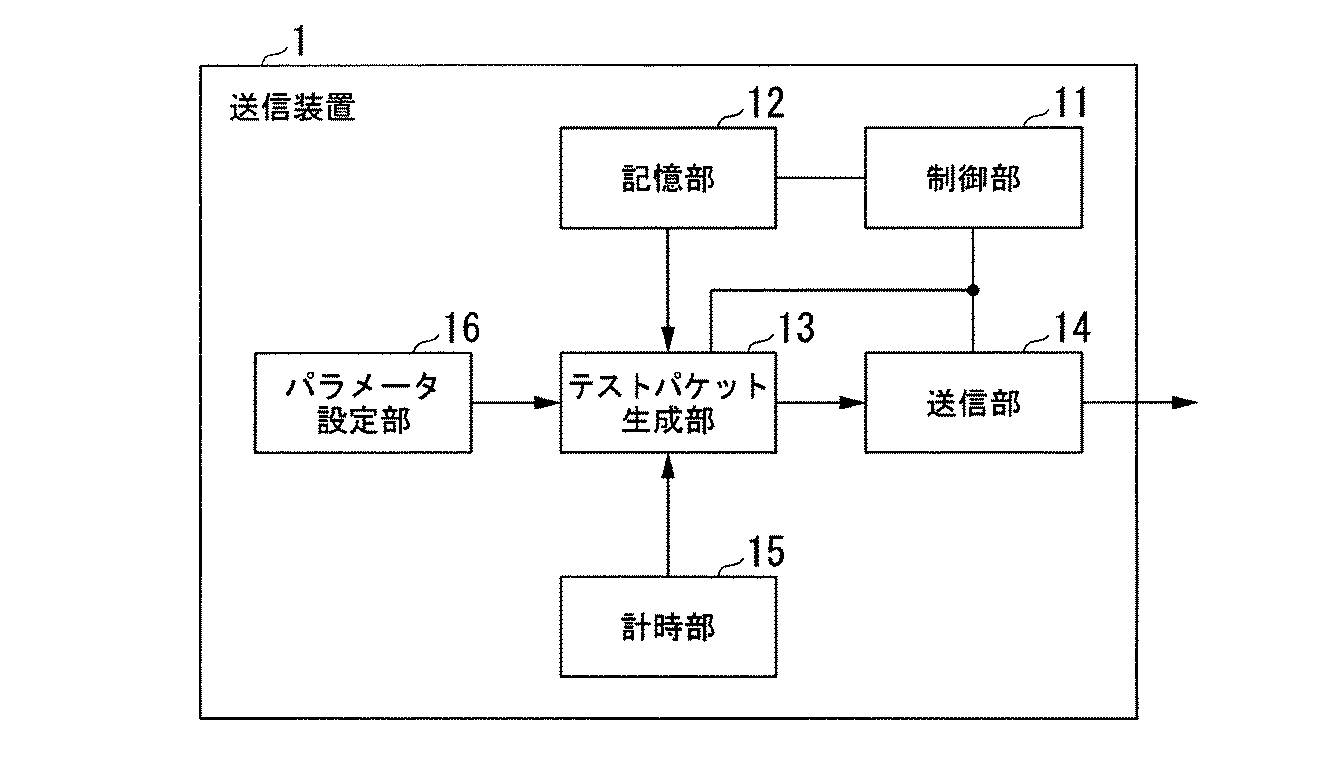
図5は、本実施形態における物理的な帯域の算出方法の概要を示した概念図である。
この図において、縦軸は片方向遅延時間OWD(つまり、伝送遅延算出値)、横軸はIPパケットのパケットサイズである。品質計測部24は、記憶部22に記憶されたテスト用のIPパケットのデータから、パケットサイズ毎に遅延代表値delayi(i=1,2,・・・,N)を算出する。本実施形態では、遅延代表値delayiは伝送遅延算出値の最小値である。次に、品質計測部24は、最小2乗法や最尤法を用いて回帰分析を行い、Liとdelayiを式(2)に線形近似する。品質計測部24は、式(2)により算出されたaの逆数(1/a)を物理的な帯域Bとする。
FIG. 5 is a conceptual diagram showing an outline of a physical bandwidth calculation method in the present embodiment.
In this figure, the vertical axis represents the one-way delay time OWD (that is, the transmission delay calculation value), and the horizontal axis represents the packet size of the IP packet. The
次に、無線区間特有の帯域の揺らぎFの算出方法について説明する。品質計測部24は、式(3)から揺らぎFを算出する。式(3)は、最小値からの揺らぎFmと時間方向の揺らぎFtに基づいた式になっている。Fm及びFtの算出方法については後述する。α1,α2及びβは、「F=Th’/B」として多変量解析により算出される。Th’は、TCPスループットの実測値であり、予め測定された値である。
Next, a method of calculating the band fluctuation F unique to the wireless section will be described. The
図6は、本実施形態における最小値からの揺らぎの概要を示した概略図である。
この図において、縦軸は片方向遅延時間OWD(つまり、伝送遅延算出値)、横軸は時間である。この図に示す例では、記憶部22は、N種類のパケットサイズ(L1,L2,・・・,Ln)のテスト用のIPパケットのデータを受信時刻順にM組記憶している。最小値からの揺らぎFmは、次の式(4)から算出される。式(4)は、遅延代表値delayiと伝送遅延算出値dij(i=1,2,・・・,N;j=1,2,・・・,M)の差に基づいた式になっている。dijは、j組目のパケットサイズLiのIPパケットの伝送遅延算出値である。
FIG. 6 is a schematic diagram showing an outline of fluctuation from the minimum value in the present embodiment.
In this figure, the vertical axis represents the one-way delay time OWD (that is, the calculated transmission delay value), and the horizontal axis represents time. In the example shown in this figure, the
図7は、本実施形態における時間方向の揺らぎの概要を示した概略図である。
この図において、縦軸は片方向遅延時間OWD(つまり、伝送遅延算出値)、横軸は時間である。時間方向の揺らぎFtは、次の式(5)から算出される。式(5)は、連続して受信されたテスト用のIPパケットの伝送遅延算出値の差に基づいた式になっている。
FIG. 7 is a schematic diagram showing an outline of fluctuation in the time direction in the present embodiment.
In this figure, the vertical axis represents the one-way delay time OWD (that is, the calculated transmission delay value), and the horizontal axis represents time. The fluctuation Ft in the time direction is calculated from the following equation (5). Expression (5) is an expression based on a difference in transmission delay calculation values of test IP packets received successively.
このように、本実施形態によれば、複数の種類のパケットサイズ別の遅延代表値から線形近似した傾きに基づいて通信品質を算出するため、より高精度に通信品質を計測することができる。また、更に揺らぎに基づいて通信品質を計測しているため、通信環境が頻繁に変化する無線区間を含むネットワークにおいても、通信品質を精度よく計測することができる。また、線形近似した傾きから物理帯域を推定しているため、物理帯域の異なるシステムが混在している場合でも、特に区別することなく通信品質を計測可能である。また、パケットサイズ毎に独立して遅延代表値及び揺らぎを算出しているため、順にパケットを送信する必要はなく、例えば、ランダムに送信したとしても同様の結果が得られる。 As described above, according to the present embodiment, the communication quality is calculated based on the slope that is linearly approximated from the delay representative values for a plurality of types of packet sizes. Therefore, the communication quality can be measured with higher accuracy. Further, since the communication quality is further measured based on fluctuations, the communication quality can be accurately measured even in a network including a wireless section where the communication environment frequently changes. In addition, since the physical band is estimated from the linearly approximated slope, communication quality can be measured without particular distinction even when systems with different physical bands are mixed. Further, since the delay representative value and fluctuation are calculated independently for each packet size, it is not necessary to transmit the packets in order. For example, the same result can be obtained even if the packets are transmitted randomly.
また、図2及び図3に示す送信装置1及び受信装置2の機能を実現するためのプログラムをコンピュータ読み取り可能な記録媒体に記録して、この記録媒体に記録されたプログラムをコンピュータシステムに読み込ませ、実行することにより、品質計測処理を行ってもよい。なお、ここでいう「コンピュータシステム」とは、OSや周辺機器等のハードウェアを含むものであってもよい。
また、「コンピュータシステム」は、WWWシステムを利用している場合であれば、ホームページ提供環境(あるいは表示環境)も含むものとする。
また、「コンピュータ読み取り可能な記録媒体」とは、フレキシブルディスク、光磁気ディスク、ROM、フラッシュメモリ等の書き込み可能な不揮発性メモリ、CD−ROM等の可搬媒体、コンピュータシステムに内蔵されるハードディスク等の記憶装置のことをいう。
Also, a program for realizing the functions of the
Further, the “computer system” includes a homepage providing environment (or display environment) if a WWW system is used.
The “computer-readable recording medium” means a flexible disk, a magneto-optical disk, a ROM, a writable nonvolatile memory such as a flash memory, a portable medium such as a CD-ROM, a hard disk built in a computer system, etc. This is a storage device.
さらに「コンピュータ読み取り可能な記録媒体」とは、インターネット等のネットワークや電話回線等の通信回線を介してプログラムが送信された場合のサーバやクライアントとなるコンピュータシステム内部の揮発性メモリ(例えばDRAM(Dynamic Random Access Memory))のように、一定時間プログラムを保持しているものも含むものとする。
また、上記プログラムは、このプログラムを記憶装置等に格納したコンピュータシステムから、伝送媒体を介して、あるいは、伝送媒体中の伝送波により他のコンピュータシステムに伝送されてもよい。ここで、プログラムを伝送する「伝送媒体」は、インターネット等のネットワーク(通信網)や電話回線等の通信回線(通信線)のように情報を伝送する機能を有する媒体のことをいう。
また、上記プログラムは、前述した機能の一部を実現するためのものであっても良い。さらに、前述した機能をコンピュータシステムにすでに記録されているプログラムとの組み合わせで実現できるもの、いわゆる差分ファイル(差分プログラム)であっても良い。
Further, the “computer-readable recording medium” refers to a volatile memory (for example, DRAM (Dynamic DRAM)) in a computer system that becomes a server or a client when a program is transmitted via a network such as the Internet or a communication line such as a telephone line. Random Access Memory)), etc., which hold programs for a certain period of time.
The program may be transmitted from a computer system storing the program in a storage device or the like to another computer system via a transmission medium or by a transmission wave in the transmission medium. Here, the “transmission medium” for transmitting the program refers to a medium having a function of transmitting information, such as a network (communication network) such as the Internet or a communication line (communication line) such as a telephone line.
The program may be for realizing a part of the functions described above. Furthermore, what can implement | achieve the function mentioned above in combination with the program already recorded on the computer system, and what is called a difference file (difference program) may be sufficient.
以上、図面を参照してこの発明の一実施形態について詳しく説明してきたが、具体的な構成は上述のものに限られることはなく、この発明の要旨を逸脱しない範囲内において様々な設計変更等をすることが可能である。 As described above, the embodiment of the present invention has been described in detail with reference to the drawings. However, the specific configuration is not limited to the above, and various design changes and the like can be made without departing from the scope of the present invention. It is possible to
1…送信装置 2…受信装置 3…無線基地局 11…制御部 12…記憶部 13…テストパケット生成部 14…送信部 15…計時部 16・・・パラメータ設定部 21…制御部 22…記憶部 23…受信部 24…品質計測部 25…計時部
DESCRIPTION OF
Claims (10)
サイズの異なるテストパケットを生成するパケット生成部と、前記無線区間経由でパケットが伝送される受信装置宛てに前記サイズの異なるテストパケットを混在させて送信する送信部と、を有する送信装置と、
前記送信装置から送信されたテストパケットを受信し、該遅延データを記録する受信部と、テストパケットのサイズ別の前記遅延データから線形近似した傾き及びテストパケットのサイズ別の前記遅延データの揺らぎに基づいて通信品質を計測する品質計測部と、を有する受信装置と、
を備えたことを特徴とする品質計測システム。 In a quality measurement system for measuring communication quality of a communication network having a wireless section in which packets are divided into wireless frames and transmitted,
A transmission device comprising: a packet generation unit that generates test packets of different sizes; and a transmission unit that transmits a mixture of test packets of different sizes to a reception device to which packets are transmitted via the wireless section;
A receiver that receives the test packet transmitted from the transmitter and records the delay data; and a linear approximation of the delay data for each size of the test packet and fluctuations in the delay data for each size of the test packet A quality measuring unit for measuring communication quality based on the receiver,
A quality measurement system characterized by comprising
送信装置から送信されたテストパケットを受信し、該受信データを記録する受信部と、
テストパケットのサイズ別の前記遅延データから線形近似した傾き及びテストパケットのサイズ別の前記遅延データの揺らぎに基づいて通信品質を計測する品質計測部と、
を有することを特徴とする受信装置。 In a receiving apparatus applied to a quality measurement system for measuring communication quality of a communication network having a wireless section in which a packet is divided into wireless frames and transmitted,
A receiving unit that receives the test packet transmitted from the transmitting device and records the received data;
A quality measuring unit that measures communication quality based on a linear approximation of the delay data for each test packet size and fluctuations of the delay data for each test packet size;
A receiving apparatus comprising:
送信装置が、サイズの異なるテストパケットを生成するパケット生成ステップと、
送信装置が、前記無線区間経由でパケットが伝送される受信装置宛てに前記サイズの異なるテストパケットを混在させて送信する送信ステップと、
受信装置が、前記送信装置から送信されたテストパケットを受信し、該受信データを記録する受信ステップと、
受信装置が、テストパケットのサイズ別の前記遅延データから線形近似した傾き及びテストパケットのサイズ別の前記遅延データの揺らぎに基づいて通信品質を計測する品質計測ステップと、
を有することを特徴とする品質計測方法。 In a quality measurement method for measuring communication quality of a communication network having a wireless section in which a packet is divided into wireless frames and transmitted,
A packet generation step in which the transmitting device generates test packets of different sizes;
A transmitting step in which the transmitting device transmits the test packets having different sizes to a receiving device to which packets are transmitted via the wireless section; and
A receiving device that receives the test packet transmitted from the transmitting device and records the received data;
A quality measurement step in which the receiving device measures communication quality based on a linear approximation of the delay data for each test packet size and fluctuations in the delay data for each test packet size;
A quality measurement method characterized by comprising:
送信装置から送信されたテストパケットを受信し、該受信データを記録する受信ステップと、
テストパケットのサイズ別の前記遅延データから線形近似した傾き及びテストパケットのサイズ別の前記遅延データの揺らぎに基づいて通信品質を計測する品質計測ステップと、
をコンピュータに実行させるためのプログラム。 In a program for measuring communication quality of a communication network having a wireless section in which packets are divided into wireless frames and transmitted,
A receiving step of receiving a test packet transmitted from a transmitting device and recording the received data;
A quality measuring step of measuring communication quality based on a linear approximation of the delay data for each test packet size and fluctuations of the delay data for each test packet size;
A program that causes a computer to execute.
Priority Applications (1)
| Application Number | Priority Date | Filing Date | Title |
|---|---|---|---|
| JP2008120342A JP2009272800A (en) | 2008-05-02 | 2008-05-02 | Quality measurement system, reception device, quality measuring method, and program |
Applications Claiming Priority (1)
| Application Number | Priority Date | Filing Date | Title |
|---|---|---|---|
| JP2008120342A JP2009272800A (en) | 2008-05-02 | 2008-05-02 | Quality measurement system, reception device, quality measuring method, and program |
Publications (1)
| Publication Number | Publication Date |
|---|---|
| JP2009272800A true JP2009272800A (en) | 2009-11-19 |
Family
ID=41438978
Family Applications (1)
| Application Number | Title | Priority Date | Filing Date |
|---|---|---|---|
| JP2008120342A Ceased JP2009272800A (en) | 2008-05-02 | 2008-05-02 | Quality measurement system, reception device, quality measuring method, and program |
Country Status (1)
| Country | Link |
|---|---|
| JP (1) | JP2009272800A (en) |
Cited By (4)
| Publication number | Priority date | Publication date | Assignee | Title |
|---|---|---|---|---|
| WO2016103674A1 (en) * | 2014-12-22 | 2016-06-30 | 日本電気株式会社 | Stream reception device, communication system, method for estimating timing of stream transmission, and recording medium |
| JP2016181784A (en) * | 2015-03-24 | 2016-10-13 | Kddi株式会社 | Communication device and calculation method |
| CN115022206A (en) * | 2022-06-01 | 2022-09-06 | 山东云天安全技术有限公司 | Network stability determination method and device, computer equipment and readable storage medium |
| CN118488120A (en) * | 2024-05-15 | 2024-08-13 | 深圳壹企服电子商务有限公司 | Network security transmission method, system, device and storage medium |
Citations (2)
| Publication number | Priority date | Publication date | Assignee | Title |
|---|---|---|---|---|
| JP2004274703A (en) * | 2003-02-19 | 2004-09-30 | Intec Netcore Inc | Router device and packet transfer control method |
| WO2005027394A1 (en) * | 2003-09-10 | 2005-03-24 | Fujitsu Limited | Transmission parameter control device |
-
2008
- 2008-05-02 JP JP2008120342A patent/JP2009272800A/en not_active Ceased
Patent Citations (2)
| Publication number | Priority date | Publication date | Assignee | Title |
|---|---|---|---|---|
| JP2004274703A (en) * | 2003-02-19 | 2004-09-30 | Intec Netcore Inc | Router device and packet transfer control method |
| WO2005027394A1 (en) * | 2003-09-10 | 2005-03-24 | Fujitsu Limited | Transmission parameter control device |
Cited By (5)
| Publication number | Priority date | Publication date | Assignee | Title |
|---|---|---|---|---|
| WO2016103674A1 (en) * | 2014-12-22 | 2016-06-30 | 日本電気株式会社 | Stream reception device, communication system, method for estimating timing of stream transmission, and recording medium |
| JP2016181784A (en) * | 2015-03-24 | 2016-10-13 | Kddi株式会社 | Communication device and calculation method |
| CN115022206A (en) * | 2022-06-01 | 2022-09-06 | 山东云天安全技术有限公司 | Network stability determination method and device, computer equipment and readable storage medium |
| CN118488120A (en) * | 2024-05-15 | 2024-08-13 | 深圳壹企服电子商务有限公司 | Network security transmission method, system, device and storage medium |
| CN118488120B (en) * | 2024-05-15 | 2024-12-10 | 深圳壹企服电子商务有限公司 | Network security transmission method, system, equipment and storage medium |
Similar Documents
| Publication | Publication Date | Title |
|---|---|---|
| JP5686133B2 (en) | Usable bandwidth measurement system, transmitter, usable bandwidth measurement method and program | |
| JP5022935B2 (en) | Quality measuring system, receiving device, quality measuring method and program | |
| US20210212008A1 (en) | Method and device for synchronizing data packets from embedded data sensors monitoring body motion of a patient | |
| JP6038296B2 (en) | Method and apparatus for allocating time frequency resources for at least one data transmission over a fast fading frequency selective channel | |
| JP2008258877A (en) | Band measuring system, communication equipment, band measuring method and band measurement program | |
| JP6517335B2 (en) | METHOD, APPARATUS, CONTROL DEVICE, AND BASE STATION FOR TREATING INTER-CELL INTERFERENCE | |
| EP3720071A2 (en) | Benchmarking of delay estimates in a 5g network for quality of service flow setup and monitoring | |
| JP6575529B2 (en) | Usable band estimation system, usable band estimation method, receiving apparatus, and control program for receiving apparatus | |
| JP2009272800A (en) | Quality measurement system, reception device, quality measuring method, and program | |
| CN107682110B (en) | Data transmission method and device and radar equipment | |
| Bao et al. | Bitrate adaptation for mobile video streaming based on buffer and channel state | |
| US9380477B2 (en) | Terminal, and system and method for monitoring wireless network | |
| JP2010213065A (en) | Packet receiving apparatus and packet receiving system | |
| JP6048102B2 (en) | Information processing system | |
| JP6502898B2 (en) | Communication quality estimation device, communication quality estimation method and program | |
| JPWO2006107046A1 (en) | Communication control device, communication terminal | |
| KR102536005B1 (en) | Method and Apparatus for Setting Reception Threshold in Backscatter Communication | |
| JPWO2017077704A1 (en) | Throughput measuring apparatus, method and program | |
| JP6559627B2 (en) | System and method for estimating available bandwidth of communication network | |
| Dräxler et al. | Anticipatory download scheduling in wireless video streaming with uncertain data rate prediction | |
| JP6294718B2 (en) | Increase point determination device, communication device, increase point determination method, and computer program | |
| Triki et al. | Anticipating resource management and QoE for mobile video streaming under imperfect prediction | |
| JP2015149658A (en) | COMMUNICATION SYSTEM, COMMUNICATION METHOD, TCP HEAD MONITORING DEVICE, AND LINE ALLOCATION DEVICE | |
| CN102624612A (en) | Transmission method and transmission device for aggregate media protocol data unit (A-mpdu) messages | |
| JP2019087905A (en) | Communication device and method, program, and communication system |
Legal Events
| Date | Code | Title | Description |
|---|---|---|---|
| A621 | Written request for application examination |
Free format text: JAPANESE INTERMEDIATE CODE: A621 Effective date: 20110131 |
|
| A521 | Written amendment |
Free format text: JAPANESE INTERMEDIATE CODE: A821 Effective date: 20110201 |
|
| A977 | Report on retrieval |
Free format text: JAPANESE INTERMEDIATE CODE: A971007 Effective date: 20120709 |
|
| A131 | Notification of reasons for refusal |
Free format text: JAPANESE INTERMEDIATE CODE: A131 Effective date: 20120717 |
|
| A521 | Written amendment |
Free format text: JAPANESE INTERMEDIATE CODE: A523 Effective date: 20120831 |
|
| A521 | Written amendment |
Free format text: JAPANESE INTERMEDIATE CODE: A821 Effective date: 20120903 |
|
| A01 | Written decision to grant a patent or to grant a registration (utility model) |
Free format text: JAPANESE INTERMEDIATE CODE: A01 Effective date: 20121218 |
|
| A045 | Written measure of dismissal of application [lapsed due to lack of payment] |
Free format text: JAPANESE INTERMEDIATE CODE: A045 Effective date: 20130423 |