JP2009254942A - Method for estimating service life of chemical filter - Google Patents
Method for estimating service life of chemical filter Download PDFInfo
- Publication number
- JP2009254942A JP2009254942A JP2008105014A JP2008105014A JP2009254942A JP 2009254942 A JP2009254942 A JP 2009254942A JP 2008105014 A JP2008105014 A JP 2008105014A JP 2008105014 A JP2008105014 A JP 2008105014A JP 2009254942 A JP2009254942 A JP 2009254942A
- Authority
- JP
- Japan
- Prior art keywords
- filter
- chemical filter
- chemical
- adsorption amount
- lifetime
- Prior art date
- Legal status (The legal status is an assumption and is not a legal conclusion. Google has not performed a legal analysis and makes no representation as to the accuracy of the status listed.)
- Pending
Links
- 239000000126 substance Substances 0.000 title claims abstract description 165
- 238000000034 method Methods 0.000 title claims description 37
- 238000010030 laminating Methods 0.000 claims abstract description 4
- 238000001179 sorption measurement Methods 0.000 claims description 97
- 238000012360 testing method Methods 0.000 claims description 41
- 239000003463 adsorbent Substances 0.000 claims description 40
- 238000011144 upstream manufacturing Methods 0.000 claims description 10
- 238000010521 absorption reaction Methods 0.000 abstract 4
- 230000002745 absorbent Effects 0.000 abstract 1
- 239000002250 absorbent Substances 0.000 abstract 1
- 239000007789 gas Substances 0.000 description 79
- AAPLIUHOKVUFCC-UHFFFAOYSA-N trimethylsilanol Chemical compound C[Si](C)(C)O AAPLIUHOKVUFCC-UHFFFAOYSA-N 0.000 description 18
- 238000005259 measurement Methods 0.000 description 13
- OKTJSMMVPCPJKN-UHFFFAOYSA-N Carbon Chemical compound [C] OKTJSMMVPCPJKN-UHFFFAOYSA-N 0.000 description 8
- 239000012535 impurity Substances 0.000 description 8
- 230000002378 acidificating effect Effects 0.000 description 7
- 239000003344 environmental pollutant Substances 0.000 description 6
- 231100000719 pollutant Toxicity 0.000 description 6
- 239000000463 material Substances 0.000 description 5
- 238000004519 manufacturing process Methods 0.000 description 4
- 238000009835 boiling Methods 0.000 description 3
- 230000007423 decrease Effects 0.000 description 3
- 238000001514 detection method Methods 0.000 description 3
- VLKZOEOYAKHREP-UHFFFAOYSA-N n-Hexane Chemical compound CCCCCC VLKZOEOYAKHREP-UHFFFAOYSA-N 0.000 description 3
- 239000004065 semiconductor Substances 0.000 description 3
- CSCPPACGZOOCGX-UHFFFAOYSA-N Acetone Chemical compound CC(C)=O CSCPPACGZOOCGX-UHFFFAOYSA-N 0.000 description 2
- 229910021536 Zeolite Inorganic materials 0.000 description 2
- 239000002253 acid Substances 0.000 description 2
- PNEYBMLMFCGWSK-UHFFFAOYSA-N aluminium oxide Inorganic materials [O-2].[O-2].[O-2].[Al+3].[Al+3] PNEYBMLMFCGWSK-UHFFFAOYSA-N 0.000 description 2
- 239000007864 aqueous solution Substances 0.000 description 2
- 230000003749 cleanliness Effects 0.000 description 2
- 239000000356 contaminant Substances 0.000 description 2
- HNPSIPDUKPIQMN-UHFFFAOYSA-N dioxosilane;oxo(oxoalumanyloxy)alumane Chemical compound O=[Si]=O.O=[Al]O[Al]=O HNPSIPDUKPIQMN-UHFFFAOYSA-N 0.000 description 2
- 238000000605 extraction Methods 0.000 description 2
- 239000003456 ion exchange resin Substances 0.000 description 2
- 229920003303 ion-exchange polymer Polymers 0.000 description 2
- 239000005416 organic matter Substances 0.000 description 2
- 229910021420 polycrystalline silicon Inorganic materials 0.000 description 2
- 229920005591 polysilicon Polymers 0.000 description 2
- 229920006395 saturated elastomer Polymers 0.000 description 2
- 239000010457 zeolite Substances 0.000 description 2
- NWUYHJFMYQTDRP-UHFFFAOYSA-N 1,2-bis(ethenyl)benzene;1-ethenyl-2-ethylbenzene;styrene Chemical compound C=CC1=CC=CC=C1.CCC1=CC=CC=C1C=C.C=CC1=CC=CC=C1C=C NWUYHJFMYQTDRP-UHFFFAOYSA-N 0.000 description 1
- JOYRKODLDBILNP-UHFFFAOYSA-N Ethyl urethane Chemical compound CCOC(N)=O JOYRKODLDBILNP-UHFFFAOYSA-N 0.000 description 1
- 229920005830 Polyurethane Foam Polymers 0.000 description 1
- 238000004378 air conditioning Methods 0.000 description 1
- 238000003795 desorption Methods 0.000 description 1
- 238000010586 diagram Methods 0.000 description 1
- 238000007599 discharging Methods 0.000 description 1
- 230000000694 effects Effects 0.000 description 1
- 239000006260 foam Substances 0.000 description 1
- -1 for example Substances 0.000 description 1
- 238000004817 gas chromatography Methods 0.000 description 1
- 238000000769 gas chromatography-flame ionisation detection Methods 0.000 description 1
- 238000002290 gas chromatography-mass spectrometry Methods 0.000 description 1
- 238000007689 inspection Methods 0.000 description 1
- 238000004255 ion exchange chromatography Methods 0.000 description 1
- 239000003960 organic solvent Substances 0.000 description 1
- 239000011496 polyurethane foam Substances 0.000 description 1
- 239000000243 solution Substances 0.000 description 1
- 238000010998 test method Methods 0.000 description 1
Images


Landscapes
- Separation Of Gases By Adsorption (AREA)
Abstract
Description
本発明は、クリーンルームや半導体製造装置の空調システム等に使用されるケミカルフィルタの寿命を推定する方法に関する。 The present invention relates to a method for estimating the lifetime of a chemical filter used in a clean room or an air conditioning system of a semiconductor manufacturing apparatus.
半導体装置の製造工程においては、空気中の不純物を除去し、空気の清浄度を高めることが不可欠である。例えば、製造工程で発生する酸性ガス、塩基性ガス、有機ガス等の汚染ガスを除去し、クリーンルーム内等の清浄度を向上させるために、ケミカルフィルタが使用される。ケミカルフィルタは、ウレタンフォーム等のフィルタ基材に吸着剤を付着して構成され、吸着剤で汚染ガスを吸着して、空気中の汚染ガスを除去するものである。 In the manufacturing process of a semiconductor device, it is indispensable to remove impurities in the air and increase the cleanliness of the air. For example, a chemical filter is used to remove pollutant gases such as acidic gas, basic gas, and organic gas generated in the manufacturing process and improve cleanliness in a clean room. The chemical filter is configured by adsorbing an adsorbent to a filter base material such as urethane foam, and adsorbs the pollutant gas with the adsorbent to remove the pollutant gas in the air.
ケミカルフィルタにおいて、吸着剤による汚染ガスの吸着が進むと吸着剤の吸着性能が低下するため、汚染ガスを所定量以上吸着したフィルタについては、新たなものに交換する必要がある。フィルタの交換時期を判定する方法としては、例えば検知管等を用いて、フィルタの上流側の不純物濃度と、下流側の不純物濃度とを測定し、これら測定値からフィルタの不純物除去効率を算出して、その除去効率が所定の値に達した時点を交換時期とする方法が知られている(例えば、特許文献1の図6参照)。 In the chemical filter, as the adsorption of the pollutant gas by the adsorbent proceeds, the adsorption performance of the adsorbent decreases. Therefore, a filter that adsorbs a predetermined amount or more of the pollutant gas needs to be replaced with a new one. As a method for determining the replacement time of the filter, for example, using a detection tube or the like, the impurity concentration on the upstream side and the impurity concentration on the downstream side of the filter are measured, and the impurity removal efficiency of the filter is calculated from these measured values. A method is known in which the time when the removal efficiency reaches a predetermined value is used as the replacement time (see, for example, FIG. 6 of Patent Document 1).
また、例えば、使用中のフィルタを取り出し、そのフィルタへの汚染物質の吸着量を測定して、残存寿命を推定する方法も知られている。この方法においては、測定された吸着量と、予め測定されたケミカルフィルタの吸着容量とを対比することにより、残存寿命を推定することができる。
ところで、半導体製造工程では、種々の汚染ガスが発生するが、その代表的なものとして、露光工程で発生するトリメチルシラノール(TMS)が知られている。TMSは、例えば、フィルタ基材に活性炭等を付着したケミカルフィルタを用いて、物理吸着によって除去される。 By the way, various pollutant gases are generated in the semiconductor manufacturing process. As a typical example, trimethylsilanol (TMS) generated in the exposure process is known. TMS is removed by physical adsorption using, for example, a chemical filter in which activated carbon or the like is attached to a filter base material.
しかし、TMSは検知管では検知しにくい傾向にあり、TMSが汚染物質として存在する場合、検知管を用いてケミカルフィルタの交換時期を判定しようとすると、検査機器や検査方法が複雑になり、交換時期を正確かつ簡便に判定するのは困難である。 However, TMS tends to be difficult to detect with a detection tube. If TMS is present as a contaminant, it would be difficult to use the detection tube to determine when to replace the chemical filter. It is difficult to determine the timing accurately and simply.
また、TMSのような有機不純物を物理吸着により除去する場合、フィルタの吸着容量は、空気中の不純物の濃度が高くなると多くなり、低くなると少なくなる傾向にある。したがって、測定された吸着量とフィルタの吸着容量を対比させて残存寿命を推定する方法では、正確に残存寿命を推定することはできない。 Further, when organic impurities such as TMS are removed by physical adsorption, the adsorption capacity of the filter tends to increase as the concentration of impurities in the air increases and decrease as the concentration decreases. Therefore, the remaining life cannot be accurately estimated by the method of estimating the remaining life by comparing the measured amount of adsorption with the adsorption capacity of the filter.
さらに、TMSは低沸点物質であるため、一旦フィルタに吸着されても、フィルタから離脱しやすい傾向にあり、TMSを対象ガス成分とすると、フィルタ寿命を正確に判定しくい傾向にある。すなわち、従来、TMSのような低沸点有機不純物を吸着するためのフィルタの交換時期を判定するのは困難であった。 Furthermore, since TMS is a low boiling point substance, once it is adsorbed to the filter, it tends to be easily detached from the filter. When TMS is used as a target gas component, the filter life tends to be difficult to accurately determine. That is, conventionally, it has been difficult to determine the replacement time of a filter for adsorbing low-boiling organic impurities such as TMS.
そこで、本発明は以上の問題点に鑑みて成されたものであり、従来寿命が推定しにくかった、TMS等の低沸点有機不純物等を吸着するためのケミカルフィルタ等であっても、簡便かつ正確に寿命を推定することができるケミカルフィルタの寿命推定方法を提供することを目的とする。 Therefore, the present invention has been made in view of the above problems, and even a chemical filter or the like for adsorbing low-boiling organic impurities such as TMS, which has been difficult to estimate the conventional life, is simple and easy. It is an object of the present invention to provide a chemical filter lifetime estimation method capable of accurately estimating the lifetime.
ケミカルフィルタは、使用開始直後においては、上流側部分において特定ガス成分の吸着量が相対的に多くなり、下流側部分において特定ガス成分の吸着量が相対的に少ない。しかしケミカルフィルタは使用とともに、上流側部分の吸着剤がガス成分によって飽和されることになり、上流側から徐々に破過されることとなる。そのため、使用時間が長くなると、下流側部分にも徐々にガス成分が吸着され、上流側部分と下流側部分のガスの吸着量の差が小さくなると共に、ガスによって飽和された部分、すなわち破過された部分は、除々に下流側に広がることになる。 The chemical filter has a relatively large adsorption amount of the specific gas component in the upstream portion immediately after the start of use, and a relatively small adsorption amount of the specific gas component in the downstream portion. However, as the chemical filter is used, the adsorbent in the upstream portion is saturated with the gas component and gradually breaks through from the upstream side. Therefore, as the usage time increases, the gas component is gradually adsorbed also in the downstream portion, the difference in the amount of gas adsorption between the upstream portion and the downstream portion becomes small, and the portion saturated with gas, that is, breakthrough The part that has been made gradually spreads downstream.
本発明に係る寿命推定方法は、このような性質を利用してケミカルフィルタの寿命を推定する方法であり、対象ガス成分を吸着可能な吸着剤が付着されており、通過された気体中の対象ガス成分を吸着して除去するケミカルフィルタの寿命を推定する寿命推定方法であって、気体の流れ方向におけるケミカルフィルタの一部の対象ガス成分の吸着量データと、ケミカルフィルタ全体の対象ガス成分の吸着量データとを対比して、ケミカルフィルタの寿命を推定することを特徴とする。または、気体の流れ方向におけるケミカルフィルタの一部の対象ガス成分の吸着量データと、上記ケミカルフィルタの一部とは流れ方向において位置が異なるケミカルフィルタの他の一部の対象ガス成分の吸着量データとを対比して、ケミカルフィルタの寿命を推定することを特徴とする。 The lifetime estimation method according to the present invention is a method for estimating the lifetime of a chemical filter by using such properties, and an adsorbent capable of adsorbing a target gas component is attached, and the target in the passed gas A lifetime estimation method for estimating the lifetime of a chemical filter that adsorbs and removes gas components, wherein the adsorption amount data of a part of the target gas component of the chemical filter in the gas flow direction and the target gas component of the entire chemical filter The lifetime of the chemical filter is estimated by comparing with the adsorption amount data. Alternatively, the adsorption amount data of a part of the target gas component of the chemical filter in the gas flow direction and the amount of adsorption of the other part of the target gas component of the chemical filter whose position is different in the flow direction from the part of the chemical filter. The life of the chemical filter is estimated by comparing with the data.
気体の流れ方向において位置が異なる、ケミカルフィルタの複数箇所の対象ガス成分の所定容積あたりの吸着量を測定することが好ましく、上記ケミカルフィルタ全体の吸着量データは、複数箇所の所定容積あたりの吸着量から求められる。また、上記ケミカルフィルタの一部及び他の一部は、少なくとも1つの上記箇所を含み、その一部及び他の一部の吸着量データは、その一部又は他の一部に含まれる少なくとも1つの箇所における所定容積あたりの吸着量から求められる。 It is preferable to measure the adsorption amount per predetermined volume of the target gas component at a plurality of locations of the chemical filter, the positions of which are different in the gas flow direction, and the adsorption amount data for the entire chemical filter is the adsorption amount per predetermined volume at the plurality of locations. It is calculated from the quantity. In addition, a part and the other part of the chemical filter include at least one part, and the adsorption amount data of the part and the other part is at least one included in the part or the other part. It is calculated | required from the adsorption amount per predetermined volume in one location.
ケミカルフィルタは、流れ方向に沿って、複数のフィルタ部分に分けられ、上記箇所それぞれはフィルタ部分それぞれに含まれ、各箇所で測定された所定容積あたりの吸着量に基づいて、フィルタ部分それぞれの吸着量データが求められることが好ましい。そして、ケミカルフィルタ全体の吸着量データは、全てのフィルタ部分の吸着量データから求められると共に、上記ケミカルフィルタの一部及び他の一部の吸着量データそれぞれは、少なくとも1つのフィルタ部分の吸着量データから求められる。 The chemical filter is divided into a plurality of filter portions along the flow direction. Each of the above portions is included in each of the filter portions, and the adsorption of each of the filter portions is based on the amount of adsorption per predetermined volume measured at each location. Preferably, quantitative data is determined. The adsorption amount data of the entire chemical filter is obtained from the adsorption amount data of all the filter parts, and the adsorption amount data of a part of the chemical filter and the other part of the adsorption amount data are the adsorption amounts of at least one filter part. Calculated from data.
ケミカルフィルタは流れ方向に沿って、対象ガス成分を吸着可能な吸着剤が付着されたフィルタ層が複数積層されて構成されており、フィルタ層それぞれは、上記フィルタ部分それぞれであることが好ましい。 The chemical filter is formed by laminating a plurality of filter layers to which an adsorbent capable of adsorbing the target gas component is attached in the flow direction, and each filter layer is preferably the filter portion.
上記ケミカルフィルタの一部の吸着量データと、ケミカルフィルタ全体の吸着量データとを対比することにより、ケミカルフィルタの寿命を推定する場合、上記ケミカルフィルタの一部は、上流側の端面から流れ方向における所定厚さ分の部分であることが好ましい。 When the lifetime of a chemical filter is estimated by comparing the adsorption amount data of a part of the chemical filter with the adsorption amount data of the entire chemical filter, a part of the chemical filter flows in the flow direction from the upstream end face. It is preferable that it is the part for predetermined thickness in.
ケミカルフィルタは、例えば、所定の使用期間使用されたフィルタであり、或いは対象ガス成分を所定濃度で含む試験用エアが、所定の流量で一定時間通過させられて、所定の使用期間使用されたとみなされたフィルタである。この場合、ケミカルフィルタ全体の吸着量データに対する一部の吸着量データの比率と、使用期間から、ケミカルフィルタの寿命が推定されることが好ましい。特に、比率が目標比率に達したとき、上記所定厚さが破過されたフィルタ厚さであるとみなし、その破過されたとみなされたフィルタ厚さと、上記使用期間とに基づき、ケミカルフィルタ全体が破過されると推定される時期をケミカルフィルタの寿命とすることが好ましい。 The chemical filter is, for example, a filter that has been used for a predetermined period of use, or it is considered that test air containing a target gas component at a predetermined concentration is allowed to pass at a predetermined flow rate for a certain period of time and used for a predetermined period of use. Is a filtered filter. In this case, it is preferable that the lifetime of the chemical filter is estimated from the ratio of the partial adsorption amount data to the adsorption amount data of the entire chemical filter and the usage period. In particular, when the ratio reaches the target ratio, the predetermined thickness is regarded as a filter thickness that has been broken through, and the entire chemical filter is based on the filter thickness that has been broken through and the period of use. It is preferable that the time estimated to be broken through is the lifetime of the chemical filter.
本発明では、試験用ケミカルフィルタに、対象ガス成分を所定濃度で含むエアを、所定流量で予め通過させ、そのときの試験用ケミカルフィルタの寿命に対するエア通過時間の比率と、試験用ケミカルフィルタにおける破過されるとみなされるフィルタ厚さとの関係を予め求めておいても良い。この場合、その求められた関係を用いて、使用された或いは使用されたとみなされたケミカルフィルタの使用時間と、そのときのフィルタの破過されたとみなされたフィルタ厚さに基づき、ケミカルフィルタの寿命を推定することが好ましい。 In the present invention, the air containing the target gas component at a predetermined concentration is passed through the test chemical filter in advance at a predetermined flow rate, and the ratio of the air passage time to the life of the test chemical filter at that time and the test chemical filter You may obtain | require previously the relationship with the filter thickness considered that it breaks through. In this case, using the determined relationship, based on the usage time of the chemical filter used or deemed used and the filter thickness considered to be broken through the filter at that time, the chemical filter It is preferable to estimate the lifetime.
本発明に係るケミカルフィルタは、対象ガス成分を含む気体が通過され、対象ガス成分を吸着するためのケミカルフィルタであって、対象ガス成分を吸着可能な吸着剤が付着されたフィルタ層が、気体の流れ方向に沿って複数積層されて構成されることを特徴とする。 The chemical filter according to the present invention is a chemical filter for adsorbing a target gas component through which a gas containing the target gas component is passed, and the filter layer to which an adsorbent capable of adsorbing the target gas component is attached is a gas. A plurality of layers are stacked along the flow direction.
本発明においては、フィルタの流れ方向における一部の吸着量データと、フィルタ全体又は他の一部の吸着量データを対比することにより、フィルタ寿命が推定される。したがって、フィルタの吸着容量を参考にせずに、さらには特別な測定機器を用いずにフィルタ寿命を推定できるので、より正確かつ簡便にフィルタ寿命を推定できる。 In the present invention, the filter lifetime is estimated by comparing a part of the adsorption amount data in the flow direction of the filter with the entire filter or another part of the adsorption amount data. Therefore, since the filter life can be estimated without referring to the adsorption capacity of the filter and without using a special measuring device, the filter life can be estimated more accurately and easily.
以下本発明について、図面を参照しつつ説明する。
図1は、本発明の第1の実施形態において、寿命推定の対象となるケミカルフィルタの構成を示す。図1に示すように、ケミカルフィルタ10は、マット状のフィルタ層11〜17が積層されて構成される。フィルタ層11〜17それぞれは、例えば三次元網状骨格構造を有するポリウレタンフォーム等のフィルタ基材に、無数の吸着剤が均等に付着されて構成される。
The present invention will be described below with reference to the drawings.
FIG. 1 shows a configuration of a chemical filter that is a target of lifetime estimation in the first embodiment of the present invention. As shown in FIG. 1, the
各フィルタ層11〜17の吸着剤は、本実施形態では、いわゆる物理吸着能を有する物理吸着剤であって、空気中のTMS等のガス状有機物を吸着することが可能である。吸着剤としては、例えば、活性炭、アルミナ、ゼオライト、ポリシリコン等が使用されるが、好ましくは活性炭が使用される。すなわち、ケミカルフィルタ10全体には、物理吸着剤が均等に付着されていることになり、ケミカルフィルタ10は、通過された気体中のガス状有機物を吸着して除去する。本実施形態におけるケミカルフィルタ10は、TMSを主に除去するためのフィルタとして使用され、下述する寿命推定方法において、対象ガス成分となるのはTMSである。
In this embodiment, the adsorbents of the
本実施形態では、各フィルタ層11〜17は、実質的に同一の構成を有している。すなわち、各フィルタ層11〜17は、互いに同一のフィルタ厚さ(積層方向の高さ)、及び縦横の長さを有している。また、フィルタ基材の種類、吸着剤の付着量、及び吸着剤の種類も互いに同一であることが好ましい。
In the present embodiment, the
本実施形態におけるケミカルフィルタ10には、フィルタ層11〜17の積層方向(フィルタ厚さ方向)に空気が通風される。すなわち、フィルタ層11〜17は、空気の流れ方向Hに沿って積層されており、フィルタ層11が最も上流側のフィルタ層、フィルタ層17が最も下流側のフィルタ層となる。
Air is passed through the
次に、本実施形態におけるケミカルフィルタ10の寿命推定方法について、図1、2を用いて説明する。本実施形態において、寿命推定の対象となるケミカルフィルタ10は、例えば、クリーンルーム等で実際に使用期間P使用されたものである。
Next, the lifetime estimation method of the
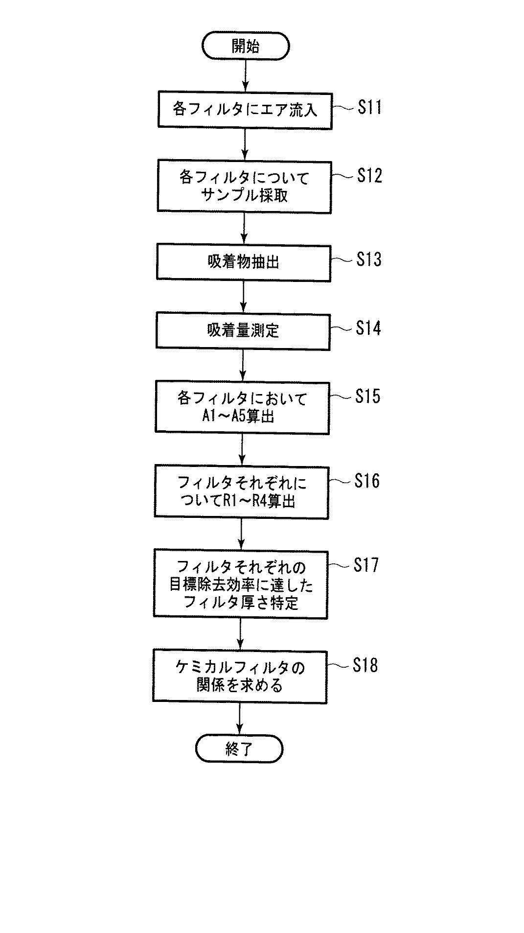
本実施形態の推定方法では、まず、ケミカルフィルタ10のフィルタ層11〜17それぞれに含まれる一部の箇所それぞれが、測定サンプルとして切り取られて採取される(ステップS1)。各フィルタ層11〜17から採取された測定サンプルは、互いに同一の容積(単位容積)を有しており、測定サンプルとして切り取られる箇所は、フィルタ層11〜17それぞれにおいて、厚さ方向の位置、および縦横の位置も同一であり、厚さ方向および縦横の位置がいずれもフィルタ層11〜17それぞれにおける中心位置であることが好ましい。このような測定サンプルは、各フィルタ層11〜17それぞれの全体を代表するサンプルとして使用されても、実際の値との誤差が生じにくい。
In the estimation method of the present embodiment, first, a part of each part included in each of the filter layers 11 to 17 of the
次に、各測定サンプルは、所定量の有機溶剤(例えば、アセトンとヘキサン等)中に入れられて、超音波振動により、吸着された有機物が抽出される(ステップS2)。抽出された有機物は、例えば、GC−FID、GC−MS等のガスクロマトグラフィーに導入され、対象ガス成分(TMS)の重量、すなわち、測定サンプルへの対象ガス成分の吸着量が測定される(ステップS3)。 Next, each measurement sample is placed in a predetermined amount of an organic solvent (for example, acetone and hexane), and the adsorbed organic matter is extracted by ultrasonic vibration (step S2). The extracted organic substance is introduced into, for example, gas chromatography such as GC-FID, GC-MS, and the weight of the target gas component (TMS), that is, the adsorption amount of the target gas component to the measurement sample is measured ( Step S3).
ステップS3で測定された対象ガス成分の吸着量は、各フィルタ層11〜17における、単位容積(所定容積)あたりの対象ガス成分の吸着量とされる。そして、その単位容積当たりの吸着量から、各フィルタ層11〜17それぞれの全容積における対象ガス成分の吸着量Aが、各フィルタ層11〜17(すなわち、単位厚さあたり)の吸着量(吸着量データ)として算出される(ステップS4)。例えば、測定された単位容積あたりの吸着量がAPである場合、単位容積をVP、各フィルタ層における全容積をVとすると、各フィルタ層それぞれにおける、対象ガス成分の吸着量AはV/VP×APで算出される。なお、以下の説明では、各フィルタ層11〜17それぞれにおけるガス状有機物の吸着量を、A1〜A7とする。
The adsorption amount of the target gas component measured in step S3 is the adsorption amount of the target gas component per unit volume (predetermined volume) in each of the filter layers 11-17. Then, from the adsorption amount per unit volume, the adsorption amount A of the target gas component in the total volume of each
次いで、上記吸着量A1〜A7から、ケミカルフィルタ10の上流側の端面10U(図1においてはフィルタ層11の上面)から所定の厚さ分の対象ガス成分の吸着量が算出される(ステップS4)。具体的には、ケミカルフィルタ10の端面10Uから1層分のフィルタ厚さT1における吸着量(A1)、端面10Uから2層分のフィルタ厚さT2における吸着量(A1+A2)、さらには端面10Uから3層分乃至7層分のフィルタ厚さT3〜T7それぞれにおける吸着量が算出される。なお、7層分のフィルタ厚さT7の吸着量は、換言すると、ケミカルフィルタ10全体の吸着量(A1+A2+・・・+A7)である。
Next, from the adsorption amounts A1 to A7, the adsorption amount of the target gas component for a predetermined thickness is calculated from the
次に、ケミカルフィルタ10全体の吸着量(フィルタ全体の吸着量データ)に対する、フィルタ厚さTn(nは1〜6の整数)分の吸着量(フィルタの一部の吸着量データ)の比率が、除去効率Rnとして算出される(ステップS5)。すなわち、端面10Uから1層分、2層分、・・・、6層分のフィルタ厚さT1、T2、・・・、T6それぞれの除去効率R1、R2、・・・、R6が、以下の式(1)に基づいて算出される。
次いで、各除去効率R1〜R6と、目標除去効率が対比され、上端10Uから何層分のフィルタ厚さTnにおいて、除去効率が目標除去効率に達したが特定される(ステップS6)。なお、目標除去効率は、ケミカルフィルタ10全体がその除去効率以下となれば、ケミカルフィルタ10を通過した空気を十分に浄化できない値に設定されている。そのため本実施形態では、端面10Uから目標除去効率に最初に達したフィルタ層までは、破過されたフィルタ層とみなされ、ステップS6では何層分のフィルタ厚さTnが破過されたかが特定される。
Next, the removal efficiencies R1 to R6 are compared with the target removal efficiencies, and it is specified that the removal efficiencies have reached the target removal efficiencies in the filter thickness Tn corresponding to the number of layers from the
そして、破過されたとみなされたフィルタ厚さTnに基づき、ケミカルフィルタ10全体が破過されると推定される時期、すなわちケミカルフィルタの寿命が推定される。例えば、除去効率R1、R2が目標除去効率に達しておらずに、除去効率R3が目標除去効率に達していた場合、上端10Uから3層分のフィルタ厚さT3で目標除去効率に達したことになる。この場合、ケミカルフィルタ10は、7層中3層のフィルタ層が破過される一方、4層のフィルタ層はまだ破過されていないとみなされる。本実施形態では、ケミカルフィルタ10は、使用時間Pに対して、比例的に破過されるとみなされ、フィルタの寿命消費率(ケミカルフィルタ10の全体寿命に対する使用期間Pの割合)は、3/7と求められる(ステップS7)。この寿命消費率から、ケミカルフィルタ10の寿命、すなわち、7層全てのフィルタ層が目標除去効率に達する期間は、比例計算により使用期間Pに7/3乗じた期間と推定される(ステップS8)。
Then, based on the filter thickness Tn considered to be broken through, the time when the
例えば目標除去効率が90%に設定され、使用期間Pが6ヶ月、除去効率R1〜R6それぞれが、76%、86%、91%、94%、97%、100%と算出された場合、上端10Uから3層分のフィルタ厚さT3で目標除去効率を超えたこととなる。この場合、フィルタの寿命消費率は3/7と判定され、使用期間P(6ヶ月)に7/3乗じた期間(14ヶ月)がフィルタの寿命と推定される。 For example, if the target removal efficiency is set to 90%, the usage period P is 6 months, and the removal efficiencies R1 to R6 are calculated as 76%, 86%, 91%, 94%, 97%, and 100%, respectively, the upper end The target removal efficiency was exceeded at the filter thickness T3 corresponding to three layers from 10U. In this case, the lifetime consumption rate of the filter is determined to be 3/7, and a period (14 months) obtained by multiplying the use period P (6 months) by 7/3 is estimated as the filter lifetime.
以上のように本実施形態においては、各フィルタ層の対象ガス成分の吸着量データを参考に、フィルタ全体に対して、どの程度の厚さまでフィルタが破過されたかが把握されて、フィルタ寿命が推定される。したがって、本実施形態では、ケミカルフィルタ10の吸着容量を参照せずにフィルタ寿命が推定されるので、通過される空気のガス濃度にかかわり無く、正確にフィルタ寿命を推定できる。
As described above, in this embodiment, referring to the adsorption amount data of the target gas component of each filter layer, it is grasped how much the filter has been broken through the entire filter, and the filter life is estimated. Is done. Therefore, in this embodiment, since the filter life is estimated without referring to the adsorption capacity of the
また、フィルタに吸着された対象ガス成分の吸着量の測定は、特殊な測定機器を用いることなく行うことができるので、本実施形態に係る寿命予知方法は簡便に実施することができる。さらに、ケミカルフィルタ10は、流れ方向Hに沿って、フィルタ層が複数積層されて構成されるので、流れ方向Hにおいて異なる箇所の測定サンプルは採取しやすくなる。
Moreover, since the measurement of the adsorption amount of the target gas component adsorbed by the filter can be performed without using a special measuring instrument, the life prediction method according to the present embodiment can be easily implemented. Furthermore, since the
さらに、一旦吸着剤に吸着されたTMS(対象ガス成分)は、一部が吸着剤から再離脱し、下流側に流れていき、ケミカルフィルタにおけるTMSの吸着量は、この再離脱の影響により変化していくことがある。しかし、本実施形態では、流れ方向Hにおいて異なる位置の吸着量データが測定されるので、上記再脱離の影響も考慮した上でフィルタ寿命が推定される。 Furthermore, part of the TMS (target gas component) once adsorbed by the adsorbent re-detaches from the adsorbent and flows downstream, and the amount of TMS adsorbed in the chemical filter changes due to the effect of this re-extraction. There are things to do. However, in the present embodiment, the adsorption amount data at different positions in the flow direction H is measured, so that the filter life is estimated in consideration of the influence of the re-desorption.
なお、本実施形態では、ステップS4において、単位容積あたりの吸着量から、各フィルタ層の吸着量A1〜A7が算出され、吸着量A1〜A7が各フィルタ層の吸着量データとされた。しかし、ステップS3で測定された単位容積あたりの吸着量そのものが、各フィルタ層の吸着量データとされても良い。単位容積あたりの吸着量は、フィルタ層11〜17それぞれの全体に吸着された特定ガス成分の吸着量そのものを示すものではないが、各フィルタ層11〜17それぞれの吸着量を指数的に表すものだからである。なお、本実施形態では、単位容積あたりの吸着量を吸着量データとしても、ステップS5で算出される除去効率R1〜R6は、吸着量A1〜A7を吸着量データとした場合と同じ値となる。 In the present embodiment, in step S4, the adsorption amounts A1 to A7 of each filter layer are calculated from the adsorption amount per unit volume, and the adsorption amounts A1 to A7 are used as the adsorption amount data of each filter layer. However, the adsorption amount per unit volume measured in step S3 may be the adsorption amount data of each filter layer. The adsorbed amount per unit volume does not indicate the adsorbed amount of the specific gas component adsorbed on the entire filter layers 11 to 17 but represents the adsorbed amount of each of the filter layers 11 to 17 exponentially. That's why. In the present embodiment, even if the adsorption amount per unit volume is the adsorption amount data, the removal efficiencies R1 to R6 calculated in step S5 are the same values as when the adsorption amounts A1 to A7 are the adsorption amount data. .
フィルタの寿命推定方法は、上記方法に限定されず、例えば、フィルタ層11〜17それぞれの吸着量データ同士を、対比させて寿命を推定しても良い。このような方法では、例えば、流れ方向におけるケミカルフィルタの一部(例えば、フィルタ層12)の吸着量データと、その一部より下流側のケミカルフィルタの他の一部(例えば、フィルタ層16)の吸着量データとを対比させ、これらの比率を求めることにより、ケミカルフィルタの寿命を推定することになる。 The filter lifetime estimation method is not limited to the above method. For example, the lifetime may be estimated by comparing the adsorption amount data of the filter layers 11 to 17 with each other. In such a method, for example, the adsorption amount data of a part of the chemical filter (for example, the filter layer 12) in the flow direction and the other part of the chemical filter downstream of the part (for example, the filter layer 16). The lifetime of the chemical filter is estimated by comparing these adsorption amount data with each other and obtaining these ratios.
なお、本実施形態においては、各フィルタ層11〜17の1箇所から、測定サンプルが得られた。しかし各フィルタ層11〜17それぞれにおいて、複数箇所から測定サンプルがサンプリングされ、これら測定サンプルで測定された吸着量の平均値が、各フィルタ層11〜17それぞれにおける単位容積あたりの吸着量とされても良い。また各フィルタ層11〜17それぞれにおいて、測定された複数の吸着量の値のうち、上記平均値に最も近似する値が、各フィルタ層11〜17それぞれにおける単位容積あたりの吸着量とされても良い。 In the present embodiment, a measurement sample was obtained from one place of each of the filter layers 11-17. However, in each of the filter layers 11 to 17, measurement samples are sampled from a plurality of locations, and the average value of the adsorption amounts measured by these measurement samples is the adsorption amount per unit volume in each of the filter layers 11 to 17. Also good. Further, in each of the filter layers 11 to 17, among the measured values of the plurality of adsorption amounts, the value closest to the average value may be the adsorption amount per unit volume in each of the filter layers 11 to 17. good.
なお、本実施形態においては、フィルタ層11〜17それぞれの厚さは互いに同一であったが、異なっていても良い。また、測定サンプルの容量(単位容量)は同一であったが互いに異なっていても良い。さらに、フィルタ層11〜17それぞれの縦又は横の長さも、互いに同一であったが、異なっていても良い。また、フィルタ層11〜17それぞれに付着される吸着剤は、対象ガス成分を吸着できる物理吸着剤であれば、互いに異なるものであっても良い。 In the present embodiment, the thicknesses of the filter layers 11 to 17 are the same, but may be different. Moreover, although the capacity | capacitance (unit capacity) of the measurement sample was the same, you may mutually differ. Furthermore, the vertical or horizontal lengths of the filter layers 11 to 17 are the same as each other, but may be different. Further, the adsorbents attached to the filter layers 11 to 17 may be different from each other as long as they are physical adsorbents capable of adsorbing the target gas component.
次に、本発明における第2の実施形態について説明する。第1の実施形態においては、使用期間Pにおいて破過されたとみなされたフィルタ厚さが厚さTnの場合、使用期間Pと、そのフィルタ厚さTnとに基づいて、ケミカルフィルタ10の寿命は、一義的に比例計算により算出された。しかし、本実施形態ではケミカルフィルタ10の寿命が、一義的に算出されず、ケミカルフィルタ10の特性を考慮した上で算出される。また、本実施形態では、後述する試験用ケミカルフィルタ10’及び実際に使用されるケミカルフィルタ10(図1参照)は共に、5層のフィルタ層から成り、フィルタ層11〜15を有している。したがって、本実施形態では、フィルタ10、10’全体の厚さはT5となる。以下、本実施形態について、第1の実施形態との相違点を説明する。
Next, a second embodiment of the present invention will be described. In the first embodiment, when the filter thickness considered to be broken through in the use period P is the thickness Tn, the lifetime of the
本実施形態では、ケミカルフィルタの特性を解析するために、図3に示すフィルタ試験装置20が用意される。フィルタ試験装置20は、筒状ケーシング21、バルブ22、流量計23、及びポンプ24を備え、筒状ケーシング21の内部には試験用ケミカルフィルタ10’が挿入装着されている。試験用ケミカルフィルタ10’は、実際に使用されるケミカルフィルタ10と同一構成のフィルタであって、未使用の試験用のフィルタである。試験用ケミカルフィルタ10’の各フィルタ層11〜15は、筒状ケーシング21内部において、その軸方向に沿って積層されている。
In this embodiment, a
筒状ケーシング21の両端それぞれには、試験用ケミカルフィルタ10’にエアを導入するための導入管25、エアを排出するための導出管26が接続される。ポンプ24は、導出管26に接続されており、ポンプ24によってエアが吸引され、導入管25から導入されたエアは、筒状ケーシング21内部の試験用ケミカルフィルタ10’を通過して、導出管26から排出される。バルブ22及び流量計23は、導出管26に設けられる。試験用ケミカルフィルタ10’を通過するエアの流量は、流量計23によって測定されつつ、バルブ22によって制御される。
Connected to both ends of the
試験用ケミカルフィルタ10’の特性を解析するための試験手順を図4を用いて説明する。まず、各フィルタ試験装置20において、導入管25からTMSを所定濃度で含む試験用エアが導入され、その試験用エアが試験用ケミカルフィルタ10’を一定流量で通過させられる。このとき、試験用ケミカルフィルタ10’は複数用意され、フィルタ10’それぞれには互いに異なる時間エアが通過させられ、すなわち、それぞれ所定時間(エア通過時間)F1、F2、・・・、Fnそれぞれの間、上記試験用エアが通過させられる(ステップS11)。
A test procedure for analyzing the characteristics of the test chemical filter 10 'will be described with reference to FIG. First, in each
次いで、各試験用ケミカルフィルタ10’において、そのエア通過時間F(F=F1、F2、・・・、Fn)が経過した時の、所定厚さT1〜T4分それぞれの除去効率R1〜R4がステップS1〜S5と同様に算出される。(ステップS12〜S16)。そして、各フィルタ10’において、上端10Uから何層分のフィルタ厚さTnにおいて、除去効率が目標除去効率に達したかが特定され、各エア通過時間F(すなわち、各フィルタ10’)における、破過されたとみなされるフィルタ厚さTn(破過厚さ)が求められる(ステップS17)。次いで、各エア通過時間Fと破過厚さとの関係が求められる(ステップS18)。
Next, in each
表1及び図5を参照にエア通過時間Fと破過厚さとの関係の求め方を、具体的に説明する。表1は、各試験用ケミカルフィルタ10’に流入されたエア通過時間Fと、目標除去効率に達したフィルタ厚さTnとの関係の一例を示す。本例では、表1から明らかなように、各試験用ケミカルフィルタに対する、エア通過時間Fそれぞれが10、20、30、40時間であるとき、目標除去効率に達したフィルタ厚さTnは、T1、T2、T3、T4となっている。また、エア通過時間Fが50時間であるとき、除去効率R1〜R4は全て目標除去効率を超えることはできていない。
A method of obtaining the relationship between the air passage time F and the breakthrough thickness will be specifically described with reference to Table 1 and FIG. Table 1 shows an example of the relationship between the air passage time F flowing into each
ここで、除去効率R1〜R4の全てが、目標除去効率を超えていないときには、フィルタ層は全て(厚さT5)が破過され、試験用ケミカルフィルタ10’は寿命に達していると判定される。そのため表1の例の試験用ケミカルフィルタ10’は、上記した試験用エアが、50時間流入されることにより寿命に達したと判定される。したがって、10、20、30、40、50時間それぞれのとき、すなわち、フィルタの寿命消費率が1/5、2/5、3/5、4/5、5/5であるとき、破過厚さTnそれぞれは、厚さT1、T2、T3、T4、T5となる。
Here, when all the removal efficiencies R1 to R4 do not exceed the target removal efficiencies, it is determined that all the filter layers (thickness T5) are broken through, and the
これにより、表1の例のフィルタは、図5のグラフ(1)に示される関数の特性を有することとなる。すなわち、破過厚さTnと、フィルタ寿命の関係は、破過厚さTnが1層分増加するごとに、全寿命の1/5ずつの寿命が消費される比例関係になる。 Thereby, the filter of the example of Table 1 will have the characteristic of the function shown by the graph (1) of FIG. That is, the relationship between the breakthrough thickness Tn and the filter lifetime is a proportional relationship in which a lifetime of 1/5 of the total lifetime is consumed each time the breakthrough thickness Tn increases by one layer.
次に、本実施形態における、使用時間Pの間実際に使用された寿命推定対象のケミカルフィルタ10(図1参照)の寿命推定方法を、再び図2を用いて説明する。なお、寿命推定対象のケミカルフィルタ10は、ステップS11〜S18の検査でフィルタ特性が求められた試験用ケミカルフィルタ10’と同一構成のフィルタである。
Next, the lifetime estimation method of the chemical filter 10 (see FIG. 1) that is the lifetime estimation target actually used during the usage time P in this embodiment will be described with reference to FIG. 2 again. The life estimation
本実施形態においても、第1の実施形態と同様に、所定の使用時間P使用された寿命推定対象のケミカルフィルタ10について、破過されたとみなされたフィルタ厚さTnが特定される(ステップS1〜S6)。
Also in the present embodiment, as in the first embodiment, the filter thickness Tn that is considered to have been broken through is specified for the
ステップS7では、グラフ(1)に示される関数から、破過されたとみなされたフィルタ厚さTnに応じて、寿命消費率が算定される。例えば、破過されたとみなされたフィルタ厚さTnが厚さT2である場合、寿命消費率は2/5と算定される。次いで、ステップS8において、第1の実施形態と同様に、寿命消費率からフィルタ寿命が推定される。例えば、寿命消費率が2/5である場合、使用期間Pに5/2を乗じた期間(P×5/2)がフィルタ寿命と推定される。 In step S7, the lifetime consumption rate is calculated from the function shown in the graph (1) in accordance with the filter thickness Tn regarded as being broken through. For example, when the filter thickness Tn considered to be broken through is the thickness T2, the lifetime consumption rate is calculated as 2/5. Next, in step S8, the filter lifetime is estimated from the lifetime consumption rate, as in the first embodiment. For example, when the lifetime consumption rate is 2/5, a period (P × 5/2) obtained by multiplying the use period P by 5/2 is estimated as the filter lifetime.
なお、表1のフィルタ例では、破過厚さTnは、エア通過時間Fの増加に対して比例的に増加したため、結局のところ、フィルタ寿命は、第1の実施形態と同様に算出される。 In the filter example shown in Table 1, the breakthrough thickness Tn increases in proportion to the increase in the air passage time F, so that the filter life is calculated in the same manner as in the first embodiment. .
次に、第2の実施形態において、表2のケミカルフィルタが使用される場合の例を説明する。表2のケミカルフィルタも同様に、ステップS11〜S18で、エア通過時間Fそれぞれが3〜100時間であるときの、目標除去効率に達するフィルタ厚さTnが求められる(表2参照)。そして、各エア通過時間Fにおける、フィルタ厚さTn(破過厚さ)から、図5に示すグラフ(2)のフィルタ特性が得られる。 Next, in the second embodiment, an example in which the chemical filter shown in Table 2 is used will be described. Similarly, in Steps S11 to S18, the chemical filter of Table 2 obtains the filter thickness Tn that reaches the target removal efficiency when the air passage time F is 3 to 100 hours (see Table 2). And the filter characteristic of the graph (2) shown in FIG. 5 is obtained from the filter thickness Tn (breakthrough thickness) at each air passage time F.
すなわち、表2のフィルタは、試験用エアが100時間流入されることにより、寿命に達したと判定される。したがって、3、10、30、60、100時間それぞれのとき、すなわち、寿命消費率が0.3/10、1/10、3/10、6/10、10/10それぞれであるとき、破過されるフィルタ厚さそれぞれは、T1、T2、T3、T4、T5それぞれになる。 That is, it is determined that the filter of Table 2 has reached the end of its life when the test air is flown in for 100 hours. Therefore, when 3, 10, 30, 60, and 100 hours each, that is, when the lifetime consumption rate is 0.3 / 10, 1/10, 3/10, 6/10, and 10/10, respectively, breakthrough occurs. Each of the filter thicknesses is T1, T2, T3, T4, and T5.
これにより、表2の例のフィルタは、図5のグラフ(2)に示される関数の特性を有することとなる。すなわち、エア通過時間Fと、破過厚さTnとの関係は、比例関係にならず、例えば、破過されたとみなされたフィルタ厚さTnがT2である場合、1/10の寿命が消費されたとされる。また、例えば、破過されたとみなされたフィルタ厚さがT4である場合、6/10の寿命が消費されたとされる。 Thereby, the filter of the example of Table 2 will have the characteristic of the function shown by the graph (2) of FIG. That is, the relationship between the air passage time F and the breakthrough thickness Tn is not a proportional relationship. For example, when the filter thickness Tn regarded as being broken through is T2, the life of 1/10 is consumed. It is said that it was done. Further, for example, when the filter thickness regarded as being broken through is T4, it is assumed that 6/10 life has been consumed.
したがって、表2の例のフィルタと同一構成のフィルタが寿命推定対象であるときには、例えば、破過されたとみなされたフィルタ厚さTnが厚さT2である場合、その寿命消費率は1/10であると算定される(ステップS7)。そして、フィルタの寿命は、寿命推定対象のフィルタの使用時間Pに10を乗じた期間であると推定される(ステップS8)。 Therefore, when a filter having the same configuration as the filter of the example of Table 2 is a life estimation target, for example, when the filter thickness Tn considered to be broken through is the thickness T2, the life consumption rate is 1/10. (Step S7). The lifetime of the filter is estimated to be a period obtained by multiplying the usage time P of the lifetime estimation target filter by 10 (step S8).
以上のように、本実施形態に係る寿命推定方法では、フィルタ特性が考慮された上で寿命が算定されている。したがって、例えば表2のフィルタのように、破過厚さTnが、エア通過時間Fに対して比例的に増加しないような場合でも、正確にフィルタ寿命を推定可能である。 As described above, in the lifetime estimation method according to this embodiment, the lifetime is calculated in consideration of the filter characteristics. Therefore, even when the breakthrough thickness Tn does not increase proportionally with respect to the air passage time F as in the filter of Table 2, for example, the filter life can be accurately estimated.
次に、第3の実施形態について、図6を用いて説明する。第1の実施形態では、ケミカルフィルタ10は、複数のフィルタ層から構成されていたが、本実施形態では、1つのケミカルフィルタ40から形成される。ケミカルフィルタ40は、フィルタ基材に無数の吸着剤が均等に付着されて構成される。ケミカルフィルタ40は、エアの流れ方向において、単位厚さを有する複数のフィルタ部分41〜47に分割されていると仮定される。複数のフィルタ部分41〜47それぞれの単位厚さそれぞれは同一厚さであり、フィルタ部分41〜47は均等に分割されているが、単位厚さは互いに異なる厚さであっても良い。
Next, a third embodiment will be described with reference to FIG. In the first embodiment, the
本実施形態では、所定の使用時間P使用された、ケミカルフィルタ40において、フィルタ部分41〜47それぞれに含まれる箇所それぞれからサンプルが採取される(ステップS1)。これら箇所は、第1の実施形態と同様に、フィルタ部分41〜47それぞれにおいて、厚さ方向の位置、および縦横の位置それぞれが同一位置に配置される。
In the present embodiment, in the
次いで、第1の実施形態と同様に、フィルタ厚さT1、T2、・・・、T6それぞれの除去効率R1、R2、・・・、R6が、上述した式(1)に基づいて算出される(ステップS2〜S6)。なお、フィルタ厚さT1、T2、・・・、T6は、1つのフィルタ部分41の厚さ、2つのフィルタ部分41、42の合計厚さ、・・・、6つのフィルタ部分41〜46の合計厚さそれぞれに対応する。その後、第1の実施形態と同様に、目標除去効率に達したフィルタ厚さTnが特定され寿命が推定される(ステップS6〜S8)。
Next, as in the first embodiment, the removal efficiencies R1, R2,..., R6 of the filter thicknesses T1, T2,..., T6 are calculated based on the above-described equation (1). (Steps S2 to S6). The filter thicknesses T1, T2,..., T6 are the thickness of one
以上のように、本発明では、ケミカルフィルタが複数のフィルタ層に分割されていないような場合でも、ケミカルフィルタの寿命は推定することが可能である。 As described above, in the present invention, the lifetime of the chemical filter can be estimated even when the chemical filter is not divided into a plurality of filter layers.
なお、第1〜第3の実施形態においては、実際に使用されたケミカルフィルタが用いられて、寿命が判定されたが、未使用のケミカルフィルタが用いられて寿命が判定されても良い。 In the first to third embodiments, the chemical filter that is actually used is used and the lifetime is determined. However, an unused chemical filter may be used and the lifetime may be determined.
例えば、未使用のケミカルフィルタが図3に示すフィルタ試験装置20に装着されて、対象ガス成分を所定濃度含む試験用エアが所定流量で一定時間通過させられて、ケミカルフィルタに強制的に対象ガス成分が吸着させられても良い。試験用エアに含まれる対象ガス成分の濃度や試験用エアの流量は、例えば、実際にケミカルフィルタが使用される環境下における、濃度や流量に近似した値に設定される。この場合、上記試験用エアが一定時間通過させられたケミカルフィルタは、一定時間使用されたケミカルフィルタとみなされる。
For example, an unused chemical filter is attached to the
また、例えば、試験用エアにおける対象ガス成分の濃度や流量は、実際にケミカルフィルタが使用される環境下における濃度や流量の数倍の値にされても良い。この場合、ケミカルフィルタは、一定時間の数倍の期間使用されたものとみなされる。このように未使用ケミカルフィルタが使用される場合も、強制的に対象ガス成分が吸着させられたケミカルフィルタは、第1の実施形態と同様に、ステップS1〜S8の手順で寿命が推定される。 Further, for example, the concentration and flow rate of the target gas component in the test air may be set to a value several times the concentration and flow rate in an environment where the chemical filter is actually used. In this case, the chemical filter is considered to have been used for a period of several times a certain time. Even when an unused chemical filter is used in this way, the lifetime of the chemical filter in which the target gas component is forcibly adsorbed is estimated by the procedure of steps S1 to S8 as in the first embodiment. .
また、例えば、寿命推定対象のケミカルフィルタの上流側に、さらに強制的に対象ガス成分が所定量吸着されたガス吸着フィルタ層が積層されていても良い。この場合には、対象ガス成分を含まない気体が、所定流量で所定時間の間、寿命推定対象のケミカルフィルタを通過させられる。これにより、本例では、対象ガス成分は、ケミカルフィルタを通過する空気によって、ガス吸着フィルタ層から離脱され、寿命推定対象のケミカルフィルタに強制的に吸着されることになる。そして、その強制的に対象ガス成分が吸着させられたケミカルフィルタは、第1の実施形態と同様に、ステップS1〜S8の手順で寿命が推定される。 In addition, for example, a gas adsorption filter layer in which a predetermined amount of the target gas component is forcibly adsorbed may be laminated on the upstream side of the chemical filter whose life is to be estimated. In this case, the gas that does not contain the target gas component is allowed to pass through the lifetime estimation target chemical filter for a predetermined time at a predetermined flow rate. Thereby, in this example, the target gas component is separated from the gas adsorption filter layer by the air passing through the chemical filter, and is forcibly adsorbed to the chemical filter that is the target of lifetime estimation. Then, the lifetime of the chemical filter in which the target gas component is forcibly adsorbed is estimated by the procedure of steps S1 to S8, as in the first embodiment.
上記各実施形態では、対象ガス成分がTMSであったが、吸着剤に吸着される他の有機物ガス成分であって良く、また吸着剤に吸着される有機物ガス成分の全てであっても良い。 In each of the above embodiments, the target gas component is TMS, but it may be another organic gas component adsorbed by the adsorbent, or may be all of the organic gas components adsorbed by the adsorbent.
上記各実施形態では、フィルタ層それぞれに使用される吸着剤としては同一の対象ガス成分を吸着できる同一タイプのものが使用されるのならば、物理吸着剤以外の吸着剤が使用されても良く、例えば化学吸着剤が使用されても良い。化学吸着剤としては、例えば、活性炭、アルミナ、ゼオライト、ポリシリコン等の物理吸着剤に酸性物質が添着されたものや、強酸性イオン交換樹脂等の酸性吸着剤が使用され、吸着剤によって吸着される対象ガス成分は、アルカリ性ガスとなる。なお、対象ガス成分は、アルカリ性ガスのうち特定の1又は2以上の成分であっても良いし、アルカリ性ガスの全ての成分であっても良い。 In each of the above embodiments, an adsorbent other than the physical adsorbent may be used as long as the same type capable of adsorbing the same target gas component is used as the adsorbent used for each filter layer. For example, a chemical adsorbent may be used. As the chemical adsorbent, for example, a physical adsorbent such as activated carbon, alumina, zeolite, polysilicon, or the like, or an acidic adsorbent such as a strongly acidic ion exchange resin is used and is adsorbed by the adsorbent. The target gas component is an alkaline gas. The target gas component may be one or more specific components of the alkaline gas, or may be all components of the alkaline gas.
化学吸着剤としては、物理吸着剤にアルカリ物質が添着されたものや、強塩基性イオン交換樹脂等のアルカリ性吸着剤が使用され、吸着剤によって吸着される対象ガス成分が酸性ガスとなっても良い。なお、対象ガス成分は、酸性ガスのうち特定の1又は2以上の成分であっても良いし、酸性ガスの全ての成分であっても良い。 As chemical adsorbents, physical adsorbents with alkaline substances or alkaline adsorbents such as strongly basic ion exchange resins are used, and the target gas component adsorbed by the adsorbent becomes acidic gas. good. Note that the target gas component may be one or more specific components of the acid gas, or may be all components of the acid gas.
吸着剤として酸性吸着剤又はアルカリ性吸着剤が使用され、対象ガス成分がアルカリ性ガス又は酸性ガス成分である場合、ステップS2、S12における抽出で使用される溶液は、アルカリ性水溶液や、酸性水溶液が使用される。また、ステップS3、S13における吸着量の測定には、例えばイオンクロマトグラフィーが使用される。 When an acidic adsorbent or an alkaline adsorbent is used as the adsorbent and the target gas component is an alkaline gas or an acidic gas component, an alkaline aqueous solution or an acidic aqueous solution is used as the solution used in the extraction in steps S2 and S12. The Moreover, ion chromatography is used for the measurement of the adsorption amount in steps S3 and S13, for example.
10、40 ケミカルフィルタ
10’ 試験用ケミカルフィルタ
10U 端面
11〜17 フィルタ層
H 流れ方向
T1〜T7 フィルタ厚さ
41〜47 フィルタ部分
10, 40 Chemical filter 10 'Chemical filter for testing 10U End face 11-17 Filter layer H Flow direction T1-T7 Filter thickness 41-47 Filter part
Claims (9)
前記気体の流れ方向における前記ケミカルフィルタの一部の前記対象ガス成分の吸着量データと、前記ケミカルフィルタ全体、又は前記一部とは前記流れ方向において位置が異なる前記ケミカルフィルタの他の一部の対象ガス成分の吸着量データとを対比して、前記ケミカルフィルタの寿命を推定することを特徴とする寿命推定方法。 An adsorbent capable of adsorbing a target gas component is attached, and is a lifetime estimation method for estimating the lifetime of a chemical filter that adsorbs and removes the target gas component in the passed gas,
The adsorption amount data of the target gas component of a part of the chemical filter in the gas flow direction and the whole of the chemical filter or the other part of the other part of the chemical filter whose position is different in the flow direction. A life estimation method for estimating the lifetime of the chemical filter by comparing with the adsorption amount data of the target gas component.
前記ケミカルフィルタ全体の吸着量データは、前記複数箇所の前記所定容積あたりの吸着量から求められ、
前記一部及び前記他の一部は、少なくとも1つの前記箇所を含み、
前記一部及び前記他の一部の吸着量データは、その一部又は他の一部に含まれる前記少なくとも1つの箇所における前記所定容積あたりの吸着量から求められることを特徴とする請求項1に記載の寿命推定方法。 Measure the adsorption amount per predetermined volume of the target gas component at a plurality of locations of the chemical filter at different positions in the gas flow direction,
The adsorption amount data of the entire chemical filter is obtained from the adsorption amount per predetermined volume of the plurality of locations,
The part and the other part include at least one of the portions,
2. The adsorption amount data of the part and the other part is obtained from the adsorption amount per predetermined volume at the at least one location included in the part or the other part. The life estimation method described in 1.
前記各箇所で測定された所定容積あたりの吸着量に基づいて、前記フィルタ部分それぞれの吸着量データを求め、
前記ケミカルフィルタ全体の吸着量データは、前記全てのフィルタ部分の吸着量データから求められ、
前記一部及び前記他の一部の吸着量データそれぞれは、少なくとも1つの前記フィルタ部分の吸着量データから求められることを特徴とする請求項2に記載の寿命推定方法。 The chemical filter is divided into a plurality of filter parts along the flow direction, and each of the points is included in each of the filter parts,
Based on the amount of adsorption per predetermined volume measured at each location, determine the amount of adsorption data for each of the filter parts,
The adsorption amount data of the entire chemical filter is obtained from the adsorption amount data of all the filter parts,
3. The lifetime estimation method according to claim 2, wherein each of the partial and other partial adsorption amount data is obtained from adsorption amount data of at least one of the filter portions.
前記フィルタ層それぞれは、前記フィルタ部分それぞれであることを特徴とする請求項3に記載の寿命推定方法。 The chemical filter is configured by laminating a plurality of filter layers attached with the adsorbent capable of adsorbing the target gas component along the flow direction,
The life estimation method according to claim 3, wherein each of the filter layers is each of the filter portions.
前記一部は、前記ケミカルフィルタの、上流側の端面から前記流れ方向における所定厚さ分の部分であることを特徴とする請求項1に記載の寿命推定方法。 By comparing the partial adsorption amount data and the adsorption amount data of the entire chemical filter, the lifetime of the chemical filter is estimated,
The lifetime estimation method according to claim 1, wherein the part is a part of a predetermined thickness in the flow direction from an upstream end face of the chemical filter.
前記ケミカルフィルタ全体の吸着量データに対する前記一部の吸着量データの比率と、前記使用期間から、ケミカルフィルタの寿命を推定すること特徴とする請求項5に記載の寿命推定方法。 The chemical filter is a filter that has been used for a predetermined period of use, or test air containing the target gas component at a predetermined concentration is allowed to pass at a predetermined flow rate for a certain period of time and is considered to have been used for a predetermined period of use. There was a filter,
6. The lifetime estimation method according to claim 5, wherein the lifetime of the chemical filter is estimated from a ratio of the partial adsorption amount data to the adsorption amount data of the entire chemical filter and the usage period.
その求められた関係を用いて、前記使用された或いは使用されたとみなされた前記ケミカルフィルタの使用時間と、そのときのフィルタの前記破過されたとみなされたフィルタ厚さに基づき、前記ケミカルフィルタの寿命を推定することを特徴とする請求項7に記載の寿命推定方法。 Air containing the target gas component at a predetermined concentration is passed through a chemical filter for testing in advance at a predetermined flow rate, and the ratio of the air passing time to the life of the chemical filter for testing at that time, and the chemical for testing Obtain in advance the relationship with the filter thickness considered to be broken through in the filter,
Using the determined relationship, the chemical filter based on the usage time of the chemical filter used or deemed used and the filter thickness considered to be the breakthrough of the filter at that time The lifetime estimation method according to claim 7, wherein the lifetime is estimated.
前記対象ガス成分を吸着可能な吸着剤が付着されたフィルタ層が、前記気体の流れ方向に沿って複数積層されて構成されることを特徴とするケミカルフィルタ。 A chemical filter for passing a gas containing a target gas component and adsorbing the target gas component,
A chemical filter, wherein a plurality of filter layers to which an adsorbent capable of adsorbing the target gas component is attached are stacked along the gas flow direction.
Priority Applications (1)
| Application Number | Priority Date | Filing Date | Title |
|---|---|---|---|
| JP2008105014A JP2009254942A (en) | 2008-04-14 | 2008-04-14 | Method for estimating service life of chemical filter |
Applications Claiming Priority (1)
| Application Number | Priority Date | Filing Date | Title |
|---|---|---|---|
| JP2008105014A JP2009254942A (en) | 2008-04-14 | 2008-04-14 | Method for estimating service life of chemical filter |
Publications (1)
| Publication Number | Publication Date |
|---|---|
| JP2009254942A true JP2009254942A (en) | 2009-11-05 |
Family
ID=41383082
Family Applications (1)
| Application Number | Title | Priority Date | Filing Date |
|---|---|---|---|
| JP2008105014A Pending JP2009254942A (en) | 2008-04-14 | 2008-04-14 | Method for estimating service life of chemical filter |
Country Status (1)
| Country | Link |
|---|---|
| JP (1) | JP2009254942A (en) |
Cited By (3)
| Publication number | Priority date | Publication date | Assignee | Title |
|---|---|---|---|---|
| JP2017506579A (en) * | 2014-12-31 | 2017-03-09 | シャオミ・インコーポレイテッド | Method, apparatus, program, and storage medium for identifying remaining usage period |
| TWI773046B (en) * | 2019-12-23 | 2022-08-01 | 美商恩特葛瑞斯股份有限公司 | Filter life indicator media and holder and method of evaluating filter |
| CN120064561A (en) * | 2024-12-27 | 2025-05-30 | 华中科技大学 | Carbon layer residual protection capacity detection method based on built-in multiple probes |
Citations (2)
| Publication number | Priority date | Publication date | Assignee | Title |
|---|---|---|---|---|
| JP2000296308A (en) * | 1999-04-13 | 2000-10-24 | Shin Nippon Air Technol Co Ltd | Maintenance method for chemical filter |
| JP2001000821A (en) * | 1999-06-21 | 2001-01-09 | Toray Ind Inc | Chemical filter unit |
-
2008
- 2008-04-14 JP JP2008105014A patent/JP2009254942A/en active Pending
Patent Citations (2)
| Publication number | Priority date | Publication date | Assignee | Title |
|---|---|---|---|---|
| JP2000296308A (en) * | 1999-04-13 | 2000-10-24 | Shin Nippon Air Technol Co Ltd | Maintenance method for chemical filter |
| JP2001000821A (en) * | 1999-06-21 | 2001-01-09 | Toray Ind Inc | Chemical filter unit |
Cited By (4)
| Publication number | Priority date | Publication date | Assignee | Title |
|---|---|---|---|---|
| JP2017506579A (en) * | 2014-12-31 | 2017-03-09 | シャオミ・インコーポレイテッド | Method, apparatus, program, and storage medium for identifying remaining usage period |
| TWI773046B (en) * | 2019-12-23 | 2022-08-01 | 美商恩特葛瑞斯股份有限公司 | Filter life indicator media and holder and method of evaluating filter |
| US11679385B2 (en) | 2019-12-23 | 2023-06-20 | Entegris, Inc. | Filter life indicator media and holder |
| CN120064561A (en) * | 2024-12-27 | 2025-05-30 | 华中科技大学 | Carbon layer residual protection capacity detection method based on built-in multiple probes |
Similar Documents
| Publication | Publication Date | Title |
|---|---|---|
| US5856198A (en) | Performance monitoring of gas-phase air filters | |
| JP6878466B2 (en) | How to determine the availability of air filters | |
| KR101169231B1 (en) | Method and system for managing apparatus for preventing air pollution | |
| US7430893B2 (en) | Systems and methods for detecting contaminants | |
| Chang et al. | Reduction of nitrate losses from filter and impactor samplers by means of concentration enrichment | |
| CN108700316B (en) | Air purifier including air filter life indicator and method for determining air filter life | |
| CN104956200B (en) | Diffusion Sampling Device | |
| US20050120775A1 (en) | Systems and methods for detecting contaminants | |
| RU2014123124A (en) | End-of-life systems for multilayer filter cartridges | |
| US9084958B2 (en) | Collecting device for gases and aerosol, methods of making, and methods of use | |
| JP2018512581A (en) | Methods for active or passive sampling of particles and gas phase organic and non-organic components in a fluid stream | |
| KR20060121858A (en) | Reactive gas filter | |
| JP2009254942A (en) | Method for estimating service life of chemical filter | |
| Vizhemehr et al. | Predicting gas-phase air-cleaning system efficiency at low concentration using high concentration results: Development of a framework | |
| Vizhemehr et al. | Gas-phase filters breakthrough models at low concentration–Effect of relative humidity | |
| JP2009236539A (en) | Device and method for concentrating and detecting selectively composite gaseous chemical substance | |
| Scahill et al. | A new method for the rapid determination of volatile organic compound breakthrough times for a sorbent at concentrations relevant to indoor air quality | |
| JP2017181244A (en) | Method for predicting life of chemical filter for removing siloxane compound gas | |
| US20240077459A1 (en) | Fluidized bed for industrial hygiene applications | |
| JP4594054B2 (en) | Life filter fan filter unit and filter life determination method using the same | |
| KR20120036511A (en) | Apparatus and method for measurement of lubricant oil vapor | |
| CN221593968U (en) | Gas-liquid separation metering system | |
| He | Model-Based Testing and Evaluation of Sorption Media for Removing Volatile Organic Compounds in Indoor Air | |
| JP7560052B2 (en) | Per- and polyfluoroalkyl compound sampler | |
| RU2516642C1 (en) | Device for determining length of operating layer of microporous carbon sorbent during absorption of vapour of organic substances |
Legal Events
| Date | Code | Title | Description |
|---|---|---|---|
| A621 | Written request for application examination |
Free format text: JAPANESE INTERMEDIATE CODE: A621 Effective date: 20110121 |
|
| A977 | Report on retrieval |
Free format text: JAPANESE INTERMEDIATE CODE: A971007 Effective date: 20111019 |
|
| A131 | Notification of reasons for refusal |
Free format text: JAPANESE INTERMEDIATE CODE: A131 Effective date: 20111025 |
|
| A02 | Decision of refusal |
Free format text: JAPANESE INTERMEDIATE CODE: A02 Effective date: 20120228 |