JP2009207898A - Intracooled percutaneous microwave ablation probe - Google Patents
Intracooled percutaneous microwave ablation probe Download PDFInfo
- Publication number
- JP2009207898A JP2009207898A JP2009048620A JP2009048620A JP2009207898A JP 2009207898 A JP2009207898 A JP 2009207898A JP 2009048620 A JP2009048620 A JP 2009048620A JP 2009048620 A JP2009048620 A JP 2009048620A JP 2009207898 A JP2009207898 A JP 2009207898A
- Authority
- JP
- Japan
- Prior art keywords
- treatment device
- tissue treatment
- fluid
- distal
- microwave tissue
- Prior art date
- Legal status (The legal status is an assumption and is not a legal conclusion. Google has not performed a legal analysis and makes no representation as to the accuracy of the status listed.)
- Granted
Links
Images


Classifications
-
- A—HUMAN NECESSITIES
- A61—MEDICAL OR VETERINARY SCIENCE; HYGIENE
- A61B—DIAGNOSIS; SURGERY; IDENTIFICATION
- A61B18/00—Surgical instruments, devices or methods for transferring non-mechanical forms of energy to or from the body
- A61B18/18—Surgical instruments, devices or methods for transferring non-mechanical forms of energy to or from the body by applying electromagnetic radiation, e.g. microwaves
- A61B18/1815—Surgical instruments, devices or methods for transferring non-mechanical forms of energy to or from the body by applying electromagnetic radiation, e.g. microwaves using microwaves
-
- A—HUMAN NECESSITIES
- A61—MEDICAL OR VETERINARY SCIENCE; HYGIENE
- A61B—DIAGNOSIS; SURGERY; IDENTIFICATION
- A61B18/00—Surgical instruments, devices or methods for transferring non-mechanical forms of energy to or from the body
- A61B18/18—Surgical instruments, devices or methods for transferring non-mechanical forms of energy to or from the body by applying electromagnetic radiation, e.g. microwaves
-
- A—HUMAN NECESSITIES
- A61—MEDICAL OR VETERINARY SCIENCE; HYGIENE
- A61B—DIAGNOSIS; SURGERY; IDENTIFICATION
- A61B17/00—Surgical instruments, devices or methods
- A61B2017/00017—Electrical control of surgical instruments
- A61B2017/00022—Sensing or detecting at the treatment site
- A61B2017/00084—Temperature
-
- A—HUMAN NECESSITIES
- A61—MEDICAL OR VETERINARY SCIENCE; HYGIENE
- A61B—DIAGNOSIS; SURGERY; IDENTIFICATION
- A61B18/00—Surgical instruments, devices or methods for transferring non-mechanical forms of energy to or from the body
- A61B2018/00005—Cooling or heating of the probe or tissue immediately surrounding the probe
- A61B2018/00011—Cooling or heating of the probe or tissue immediately surrounding the probe with fluids
- A61B2018/00023—Cooling or heating of the probe or tissue immediately surrounding the probe with fluids closed, i.e. without wound contact by the fluid
-
- A—HUMAN NECESSITIES
- A61—MEDICAL OR VETERINARY SCIENCE; HYGIENE
- A61B—DIAGNOSIS; SURGERY; IDENTIFICATION
- A61B18/00—Surgical instruments, devices or methods for transferring non-mechanical forms of energy to or from the body
- A61B2018/00571—Surgical instruments, devices or methods for transferring non-mechanical forms of energy to or from the body for achieving a particular surgical effect
- A61B2018/00577—Ablation
Landscapes
- Health & Medical Sciences (AREA)
- Surgery (AREA)
- Life Sciences & Earth Sciences (AREA)
- Biomedical Technology (AREA)
- Medical Informatics (AREA)
- Nuclear Medicine, Radiotherapy & Molecular Imaging (AREA)
- Electromagnetism (AREA)
- Engineering & Computer Science (AREA)
- Physics & Mathematics (AREA)
- Heart & Thoracic Surgery (AREA)
- Otolaryngology (AREA)
- Molecular Biology (AREA)
- Animal Behavior & Ethology (AREA)
- General Health & Medical Sciences (AREA)
- Public Health (AREA)
- Veterinary Medicine (AREA)
- Surgical Instruments (AREA)
Abstract
【課題】マイクロ波組織治療デバイスを提供すること。
【解決手段】デバイスは、近位および遠位端を有し、外側導電体と、外側導電体内に配置され、一部分は管腔および長手方向に延びる少なくとも1つのチャンネルを画定する、誘電材料と、遠位放射セクションを有し、一部分は誘電材料の管腔内に部分的に配置された内側導電体と、外側導電体の遠位端近くに配置された密封バリアと、該密封バリア近くに配置され内側導電体の遠位の放射セクションと内側導電体の遠位の放射セクションの周りに部分的に配置されたシースとを含み、空洞が放射部分に画定される放射部分を含む、アンテナアセンブリと、入口および出口導管を含み、これらは、誘電材料の長手方向に延びるチャンネルに部分的に配置され、流体を循環させるように構成され、空洞と流体連通し、内側導電体の放射セクションの一部分が流体と部分的に流体接触する、冷却システムとを備えている。
【選択図】図1A microwave tissue treatment device is provided.
The device has a proximal and distal ends, an outer conductor, a dielectric material disposed within the outer conductor and defining a lumen and at least one channel extending longitudinally; A distal radiating section, a portion of the inner conductor partially disposed within the lumen of the dielectric material, a sealing barrier disposed near the distal end of the outer conductor, and disposed near the sealing barrier; An antenna assembly comprising a distal radiating section of the inner conductor and a sheath partially disposed about the distal radiating section of the inner conductor, the radiating portion having a cavity defined in the radiating portion; Inlet and outlet conduits, which are partially disposed in a longitudinally extending channel of the dielectric material, configured to circulate fluid, in fluid communication with the cavity, and to the radiating section of the inner conductor. A portion is in fluid partially fluid contact, and a cooling system.
[Selection] Figure 1
Description
(関連出願の引用)
本出願は、Kenlyn Bonnらによって2008年3月3日に出願された「INTRACOOLED PERCUTANEOUS MICROWAVE ABLATION PROBE」と題する米国仮出願第61/033,196号に対する優先権の利益を請求し、該米国仮出願は、本明細書において参考として援用されている。
(Citation of related application)
This application claims priority benefit to US Provisional Application No. 61 / 033,196, entitled “INTRACOOLED PERCUTANEOUS MICROWAVE ABOVE PROBE”, filed March 3, 2008 by Kenlyn Bonn et al. Is incorporated herein by reference.
(技術分野)
本開示は概して、組織を治療または切除する治療的用途に使用されるマイクロ波アンテナに関する。さらに詳細には、本開示は、かかる治療的用途に使用されるマイクロ波アンテナの温度を調節、維持、かつ/または制御するデバイスおよび方法に関する。
(Technical field)
The present disclosure relates generally to microwave antennas used in therapeutic applications to treat or ablate tissue. More particularly, the present disclosure relates to devices and methods for adjusting, maintaining and / or controlling the temperature of microwave antennas used in such therapeutic applications.
(関連技術の背景)
マイクロ波技術を使用する多くの処置およびデバイスは、組織の治療、凝固、標的切除において適用され得ることで周知である。かかる処置の間、モノポール、ダイポール、または多様な螺旋形状のマイクロ波プローブアンテナは通常、当技術分野において従来行なわれているように、腹腔鏡的または経皮的のいずれかで患者の中に前進させられ、標的組織に達する。
(Background of related technology)
Many procedures and devices using microwave technology are well known to be applicable in tissue therapy, coagulation, and targeted ablation. During such procedures, monopoles, dipoles, or various helically shaped microwave probe antennas are typically placed in a patient either laparoscopically or percutaneously, as is conventionally done in the art. Advances and reaches the target tissue.
マイクロ波プローブの導入後、マイクロ波エネルギーが標的組織に送達され、これによって、アンテナの外側表面が時として、オーム加熱を介して不必要に高温に達する。さらに、または、フィードライン(これを通してエネルギーが電源からアンテナに伝えられる)における損失は、アンテナの加熱に寄与し得る。かかる温度にさらされるとき、治療部位および周囲の組織は、望ましくない影響を受け得る。 After introduction of the microwave probe, microwave energy is delivered to the target tissue, thereby causing the outer surface of the antenna to occasionally reach an unnecessarily high temperature via ohmic heating. Additionally or alternatively, losses in the feed line (through which energy is transferred from the power source to the antenna) can contribute to heating of the antenna. When exposed to such temperatures, the treatment site and surrounding tissue can be undesirably affected.
不必要に高い温度、および対応する組織に対する望ましくない影響を防止するために、多くの様々な冷却方法が従来使用されている。例えば、マイクロ波プローブが、外部の冷却ジャケットを含み得る。しかしながら、これらのジャケットを使用すると、全体的な大きさ、すなわち器具の口径の大きさが増加し、従って処置の侵襲性が高まる。従って、治療の間に不必要に温度が高くなること、およびデバイスの口径の大きさが増大することを防止し、それによって組織に対する望ましくない影響を最小とするための冷却システムを含む、改良されたマイクロ波組織治療デバイスに対する継続するニーズが、当技術分野において存在する。 Many different cooling methods are conventionally used to prevent unnecessarily high temperatures and undesirable effects on the corresponding tissue. For example, a microwave probe can include an external cooling jacket. However, the use of these jackets increases the overall size, i.e. the size of the caliber of the instrument, and thus increases the invasiveness of the procedure. Thus, improved, including a cooling system to prevent unnecessarily high temperatures during treatment and increase in device caliber size, thereby minimizing undesirable effects on tissue. There is a continuing need in the art for a microwave tissue treatment device.
本開示の一局面において、組織の治療または切除のためのマイクロ波組織治療デバイスが開示される。マイクロ波組織治療デバイスは、近位端および遠位端を有するアンテナアセンブリを含む。アンテナアセンブリは、細長い部材と、該細長い部材内に位置決めされた外側の導電体と、該外側の導電体内に配置され、管腔および長手方向に延びる1つ以上のチャンネルを画定する誘電材料と、遠位の放射セクションとを含み、該管腔内に少なくとも部分的に配置された内側の導電体と、該外側の導電体の遠位端の近くに配置された密封バリアと、放射部分と、冷却システムとを含む。 In one aspect of the present disclosure, a microwave tissue treatment device for tissue treatment or ablation is disclosed. The microwave tissue treatment device includes an antenna assembly having a proximal end and a distal end. The antenna assembly includes an elongate member, an outer conductor positioned within the elongate member, a dielectric material disposed within the outer conductor and defining a lumen and one or more channels extending longitudinally; An inner conductor disposed at least partially within the lumen, a sealing barrier disposed near a distal end of the outer conductor, and a radiating portion. A cooling system.
放射部分は、密封バリアの近くに配置され、内側導電体の放射セクションとこの放射セクションの周りに少なくとも部分的に配置された、近位端および遠位端を備えているシースとを含み、少なくとも1つの空洞を画定する。該少なくとも1つの空洞は、2つ以上の領域、例えば近位領域と、中間領域と、遠位領域とを含み得る。一実施形態において、空洞の領域は、空洞内に配置された1つ以上のバッフル部材によって少なくとも部分的に画定され得る。さらに、バッフル部材は、空洞内に少なくとも部分的に軸方向の2つ以上の寸法も画定する。 The radiating portion is disposed near the sealing barrier and includes a radiating section of the inner conductor and a sheath having a proximal end and a distal end, at least partially disposed about the radiating section, One cavity is defined. The at least one cavity may include two or more regions, such as a proximal region, an intermediate region, and a distal region. In one embodiment, the cavity region may be at least partially defined by one or more baffle members disposed within the cavity. Further, the baffle member also defines two or more axial dimensions at least partially within the cavity.
冷却システムは、アンテナアセンブリを通して流体を循環させるような構成および大きさとされる入口導管と出口導管とを含む。本開示の一実施形態において、流体は、水、食塩水、塩化アンモニウム、硝酸ナトリウム、塩化カリウムから成る群から選択される熱散逸流体であり得る。入口導管および出口導管は、誘電材料のチャンネルまたはチャンネル(複数)内に少なくとも部分的に配置され、少なくとも1つの空洞と連通し、その結果放射セクションの少なくとも一部分は、流体と接触する。 The cooling system includes an inlet conduit and an outlet conduit configured and sized to circulate fluid through the antenna assembly. In one embodiment of the present disclosure, the fluid may be a heat dissipating fluid selected from the group consisting of water, saline, ammonium chloride, sodium nitrate, potassium chloride. The inlet conduit and outlet conduit are at least partially disposed within the channel or channels of dielectric material and communicate with at least one cavity so that at least a portion of the radiating section is in contact with the fluid.
誘電材料を貫通するチャンネルは、第1のチャンネルと第2のチャンネルを少なくとも含み得ることが想定される。一実施形態において、入口部材は、第1のチャンネルに少なくとも部分的に配置され得、出口部材は、第2のチャンネルに少なくとも部分的に配置され得る。 It is envisioned that the channel through the dielectric material may include at least a first channel and a second channel. In one embodiment, the inlet member can be at least partially disposed in the first channel and the outlet member can be at least partially disposed in the second channel.
マイクロ波組織治療デバイスは、アンテナアセンブリの遠位端に配置される間通用部材も含み得ることがさらに想定される。アンテナアセンブリは、密封バリアの近位に、かつ少なくとも部分的に細長い部材の周りに配置される接続ハブをさらに含み得る。接続ハブは、冷却システムの入口部材および出口部材を受け入れるような構成および大きさとされる少なくとも1つの導管を含む。 It is further envisioned that the microwave tissue treatment device may also include a breakthrough member disposed at the distal end of the antenna assembly. The antenna assembly may further include a connection hub disposed proximate the sealing barrier and at least partially around the elongated member. The connection hub includes at least one conduit configured and sized to receive an inlet member and an outlet member of the cooling system.
アンテナアセンブリの一実施形態において、外側の導電体は、冷却システムの入口部材および出口部材を受け入れるような構成および大きさとされる1つ以上のアパーチャを含み得る。さらに、または代替として、マイクロ波組織治療は、放射セクションに動作可能に接続される少なくとも1つの温度センサも含み得る。 In one embodiment of the antenna assembly, the outer conductor may include one or more apertures configured and sized to receive the inlet and outlet members of the cooling system. Additionally or alternatively, the microwave tissue treatment may also include at least one temperature sensor operably connected to the radiating section.
本開示の別の局面において、改良されたマイクロ波組織治療デバイスが開示される。改良されたマイクロ波組織治療デバイスは、外側の導電体と、放射セクションを備えた内側の導電体と、放射部分とを含み、該放射部分は、内側の導電体の放射セクションと放射セクションの周りに少なくとも部分的に配置されたシースとを含み、少なくとも1つの空洞を画定する。デバイスはまた、放射セクションと流体連通する入口導管および出口導管を備えている冷却システムと、外側の導電体内に配置された誘電材料とを含む。誘電材料は、誘電材料を貫通する管腔と1つ以上のチャンネルとを含む。誘電材料を貫通する管腔は、内側の導電体の少なくとも一部分を少なくとも部分的に受け入れるような構成および大きさとされ、誘電材料を貫通するチャンネルは、入口導管および出口導管を少なくとも部分的に受け入れるような構成および大きさとされる。 In another aspect of the present disclosure, an improved microwave tissue treatment device is disclosed. An improved microwave tissue treatment device includes an outer conductor, an inner conductor with a radiating section, and a radiating portion, the radiating portion surrounding the radiating section and the radiating section of the inner conductor. And at least a portion of the sheath disposed to define at least one cavity. The device also includes a cooling system comprising an inlet conduit and an outlet conduit in fluid communication with the radiating section, and a dielectric material disposed within the outer conductor. The dielectric material includes a lumen through the dielectric material and one or more channels. The lumen through the dielectric material is configured and sized to at least partially receive at least a portion of the inner conductor, and the channel through the dielectric material is at least partially to receive the inlet conduit and the outlet conduit. The structure and size.
一実施形態において、冷却システムは、誘電材料を長手方向に貫通する第1のチャンネルと第2のチャンネルとを含む。第1のチャンネルおよび第2のチャンネルは、入口導管および出口導管をそれぞれ少なくとも部分的に収容する。 In one embodiment, the cooling system includes a first channel and a second channel that extend longitudinally through the dielectric material. The first channel and the second channel each at least partially contain an inlet conduit and an outlet conduit.
別の実施形態において、シースによって画定された少なくとも1つの空洞は、少なくとも2つの領域を含み得る。この実施形態において、改良されたマイクロ波組織治療は、1つ以上のバッフル部材をさらに含み得、該1つ以上のバッフル部材は、少なくとも1つの空洞内に配置され、それによって空洞を少なくとも2つの領域に分割する。 In another embodiment, the at least one cavity defined by the sheath can include at least two regions. In this embodiment, the improved microwave tissue treatment may further include one or more baffle members, wherein the one or more baffle members are disposed within the at least one cavity, thereby separating the cavity into at least two Divide into areas.
本開示のさらに別の局面において、内側の導電体と、外側の導電体と、誘電材料とを含むマイクロ波アンテナを冷却する方法が開示される。開示される方法は、(i)冷却システムを提供するステップであって、該冷却システムは、誘電材料内に配置されてマイクロ波アンテナと流体連通する1つ以上の入口導管および出口導管を備えている、ステップと(ii)冷却流体が内側の導電体の少なくとも一部分と流体連通するように、冷却流体を冷却システムを通して循環させるステップとを含む。 In yet another aspect of the present disclosure, a method of cooling a microwave antenna including an inner conductor, an outer conductor, and a dielectric material is disclosed. The disclosed method comprises the steps of (i) providing a cooling system, the cooling system comprising one or more inlet and outlet conduits disposed in the dielectric material and in fluid communication with the microwave antenna. And (ii) circulating the cooling fluid through the cooling system such that the cooling fluid is in fluid communication with at least a portion of the inner conductor.
代替の実施形態において、開示された方法は、内側の導電体と動作可能に接続された少なくとも1つの温度センサによって内側の導電体の温度をモニタするステップ、および/または冷却システムと連通するポンプによって冷却流体の循環を調節するステップをさらに包含し得る。 In an alternative embodiment, the disclosed method includes monitoring the temperature of the inner conductor by at least one temperature sensor operably connected to the inner conductor and / or by a pump in communication with the cooling system. The method may further include adjusting the circulation of the cooling fluid.
従って、本発明は以下の項目を提供する。 Accordingly, the present invention provides the following items.
(項目1)
マイクロ波組織治療デバイスであって、
近位端および遠位端を有するアンテナアセンブリであって、該アンテナアセンブリは、
外側の導電体と、
該外側の導電体内に配置された誘電材料であって、該誘電材料の少なくとも一部分は、管腔および長手方向に延びる少なくとも1つのチャンネルを画定する、誘電材料と、
遠位の放射セクションを有する内側の導電体であって、該内側の導電体の少なくとも一部分は、該誘電材料の該管腔内に少なくとも部分的に配置された、内側の導電体と、
該外側の導電体の遠位端の近くに配置された密封バリアと、
該密封バリアの近くに配置された放射部分であって、該放射部分は、該内側導電体の該遠位の放射セクションと該内側の導電体の該遠位の放射セクションの周りに少なくとも部分的に配置されたシースとを含み、その結果少なくとも1つの空洞が該放射部分の中に画定される、放射部分と
を含む、アンテナアセンブリと、
入口導管と出口導管とを含む冷却システムであって、該入口導管および該出口導管は、該誘電材料の該長手方向に延びる少なくとも1つのチャンネル内に少なくとも部分的に配置され、かつ流体を循環させるように構成され、該入口導管および該出口導管は、該少なくとも1つ空洞と流体連通し、その結果該内側の導電体の該放射セクションの少なくとも一部分は、該流体と少なくとも部分的に流体接触する、冷却システムと
を備えている、デバイス。
(Item 1)
A microwave tissue treatment device,
An antenna assembly having a proximal end and a distal end, the antenna assembly comprising:
An outer conductor,
A dielectric material disposed within the outer conductor, wherein at least a portion of the dielectric material defines a lumen and at least one channel extending longitudinally;
An inner conductor having a distal radiating section, wherein at least a portion of the inner conductor is at least partially disposed within the lumen of the dielectric material;
A sealing barrier disposed near the distal end of the outer conductor;
A radiating portion disposed near the sealing barrier, the radiating portion at least partially around the distal radiating section of the inner conductor and the distal radiating section of the inner conductor An antenna assembly comprising: a radiating portion including: a radiating portion, wherein the radiating portion is defined in the radiating portion;
A cooling system including an inlet conduit and an outlet conduit, wherein the inlet conduit and the outlet conduit are at least partially disposed in the longitudinally extending channel of the dielectric material and circulate fluid. The inlet conduit and the outlet conduit are in fluid communication with the at least one cavity so that at least a portion of the radiating section of the inner conductor is at least partially in fluid contact with the fluid. A device comprising a cooling system.
(項目2)
上記アンテナアセンブリの遠位端に支持された間通用部材をさらに含む、項目1に記載のマイクロ波組織治療デバイス。
(Item 2)
The microwave tissue treatment device of item 1, further comprising an interleaving member supported at a distal end of the antenna assembly.
(項目3)
上記誘電材料の上記長手方向に延びる少なくとも1つのチャンネルは、第1のチャンネルと第2のチャンネルとを少なくとも含む、項目1に記載のマイクロ波組織治療デバイス。
(Item 3)
The microwave tissue treatment device of item 1, wherein the at least one channel extending in the longitudinal direction of the dielectric material includes at least a first channel and a second channel.
(項目4)
上記入口導管は、上記第1のチャンネルに少なくとも部分的に配置され、上記出口導管は、上記第2のチャンネルに少なくとも部分的に配置される、項目3に記載のマイクロ波組織治療デバイス。
(Item 4)
4. The microwave tissue treatment device of item 3, wherein the inlet conduit is at least partially disposed in the first channel and the outlet conduit is at least partially disposed in the second channel.
(項目5)
上記アンテナアセンブリは、細長い部材の周りに少なくとも部分的に配置された接続ハブをさらに含み、該接続ハブは、上記密封バリアの近位に位置する、項目1に記載のマイクロ波組織治療デバイス。
(Item 5)
The microwave tissue treatment device of item 1, wherein the antenna assembly further includes a connection hub disposed at least partially around an elongate member, the connection hub being located proximal to the sealing barrier.
(項目6)
上記流体は熱散逸流体である、項目1に記載のマイクロ波組織治療デバイス。
(Item 6)
(項目7)
上記熱散逸流体は、水、食塩水、塩化アンモニウム、硝酸ナトリウム、塩化カリウム、および気体から成る群から選択される、項目6に記載のマイクロ波組織治療デバイス。
(Item 7)
Item 7. The microwave tissue treatment device of item 6, wherein the heat dissipation fluid is selected from the group consisting of water, saline, ammonium chloride, sodium nitrate, potassium chloride, and gas.
(項目8)
上記遠位の放射セクションに結合された温度センサをさらに含む、項目1に記載のマイクロ波組織治療デバイス。
(Item 8)
The microwave tissue treatment device of item 1, further comprising a temperature sensor coupled to the distal radiating section.
(項目9)
上記接続ハブは、上記少なくとも1つの入口導管および上記少なくとも1つの出口導管を受け入れるように構成された少なくとも1つの導管を含む、項目5に記載のマイクロ波組織治療デバイス。
(Item 9)
6. The microwave tissue treatment device of item 5, wherein the connection hub includes at least one conduit configured to receive the at least one inlet conduit and the at least one outlet conduit.
(項目10)
上記外側の導電体は、上記少なくとも1つの入口導管を受け入れるように構成された少なくとも第1のアパーチャと、上記少なくとも1つの出口導管を受け入れるように構成された少なくとも第2のアパーチャとを含む、項目1に記載のマイクロ波組織治療デバイス。
(Item 10)
The outer conductor includes at least a first aperture configured to receive the at least one inlet conduit and at least a second aperture configured to receive the at least one outlet conduit. 2. The microwave tissue treatment device according to 1.
(項目11)
上記放射部分の上記少なくとも1つの空洞は、少なくとも2つの領域を含む、項目1に記載のマイクロ波組織治療デバイス。
(Item 11)
The microwave tissue treatment device of item 1, wherein the at least one cavity of the radiating portion includes at least two regions.
(項目12)
上記少なくとも1つの空洞内に配置された少なくとも1つのバッフル部材であって、該少なくとも1つのバッフル部材は、上記少なくとも2つの領域を少なくとも部分的に画定する、少なくとも1つのバッフル部材をさらに含む、項目11に記載のマイクロ波組織治療デバイス。
(Item 12)
At least one baffle member disposed within the at least one cavity, the at least one baffle member further comprising at least one baffle member that at least partially defines the at least two regions. 11. The microwave tissue treatment device according to 11.
本発明は、以下の項目も提供する。 The present invention also provides the following items.
(項目1a)
マイクロ波組織治療デバイスであって、
近位端および遠位端を有するアンテナアセンブリであって、該アンテナアセンブリは、
細長い部材と、
該細長い部材内に位置決めされた外側の導電体と、
該外側の導電体内に配置された誘電材料であって、該誘電材料の少なくとも一部分は、管腔および長手方向に延びる少なくとも1つのチャンネルを画定する、誘電材料と、
遠位の放射セクションを有する内側の導電体であって、該内側の導電体の少なくとも一部分は、該誘電材料の該管腔内に少なくとも部分的に配置された、内側の導電体と、
該外側の導電体の遠位端の近くに配置された密封バリアと、
該密封バリアの近くに配置された放射部分であって、該放射部分は、該内側導電体の該遠位の放射セクションと該内側コンダクの該遠位の放射セクションの周りに少なくとも部分的に配置されたシースとを含み、その結果少なくとも1つの空洞が該放射部分に画定される、放射部分と
を含む、アンテナアセンブリと、
入口導管と出口導管とを含む冷却システムであって、該入口導管および該出口導管は、該誘電材料の該長手方向に延びる少なくとも1つのチャンネル内に少なくとも部分的に配置され、かつ流体を循環させるような構成および大きさとされ、該入口導管および該出口導管は、該少なくとも1つ空洞と流体連通し、その結果該内側の導電体の該放射セクションの少なくとも一部分は、該流体と少なくとも部分的に流体接触する、冷却システムと
を備えている、デバイス。
(Item 1a)
A microwave tissue treatment device,
An antenna assembly having a proximal end and a distal end, the antenna assembly comprising:
An elongated member;
An outer conductor positioned within the elongated member;
A dielectric material disposed within the outer conductor, wherein at least a portion of the dielectric material defines a lumen and at least one channel extending longitudinally;
An inner conductor having a distal radiating section, wherein at least a portion of the inner conductor is at least partially disposed within the lumen of the dielectric material;
A sealing barrier disposed near the distal end of the outer conductor;
A radiating portion disposed near the sealing barrier, the radiating portion being at least partially disposed about the distal radiating section of the inner conductor and the distal radiating section of the inner conductor; An antenna assembly comprising: a radiating portion; and at least one cavity defined in the radiating portion;
A cooling system including an inlet conduit and an outlet conduit, wherein the inlet conduit and the outlet conduit are at least partially disposed in the longitudinally extending channel of the dielectric material and circulate fluid. The inlet conduit and the outlet conduit are in fluid communication with the at least one cavity so that at least a portion of the radiating section of the inner conductor is at least partially with the fluid. A device in fluid contact with a cooling system.
(項目2a)
上記アンテナアセンブリの遠位端に支持された間通用部材をさらに含む、項目1aに記載のマイクロ波組織治療デバイス。
(Item 2a)
The microwave tissue treatment device of item 1a, further comprising an interleaving member supported on a distal end of the antenna assembly.
(項目3a)
上記誘電材料の上記長手方向に延びる少なくとも1つのチャンネルは、第1のチャンネルと第2のチャンネルとを少なくとも含む、項目1aに記載のマイクロ波組織治療デバイス。
(Item 3a)
The microwave tissue treatment device of item 1a, wherein the at least one channel extending in the longitudinal direction of the dielectric material includes at least a first channel and a second channel.
(項目4a)
上記冷却システムの上記入口導管は、上記第1のチャンネルに少なくとも部分的に配置され、該冷却システムの上記出口導管は、上記第2のチャンネルに少なくとも部分的に配置される、項目3aに記載のマイクロ波組織治療デバイス。
(Item 4a)
The entry of item 3a, wherein the inlet conduit of the cooling system is at least partially disposed in the first channel and the outlet conduit of the cooling system is at least partially disposed in the second channel. Microwave tissue treatment device.
(項目5a)
上記アンテナアセンブリは、細長い部材の周りに少なくとも部分的に配置された接続ハブをさらに含み、該接続ハブは、上記密封バリアの近位に位置する、項目1aに記載のマイクロ波組織治療デバイス。
(Item 5a)
The microwave tissue treatment device of item 1a, wherein the antenna assembly further includes a connection hub disposed at least partially around an elongated member, the connection hub being located proximal to the sealing barrier.
(項目6a)
上記流体は熱散逸流体である、項目1aに記載のマイクロ波組織治療デバイス。
(Item 6a)
The microwave tissue treatment device of item 1a, wherein the fluid is a heat dissipating fluid.
(項目7a)
上記熱散逸流体は、水、食塩水、塩化アンモニウム、硝酸ナトリウム、塩化カリウム、および気体から成る群から選択される、項目6aに記載のマイクロ波組織治療デバイス。
(Item 7a)
The microwave tissue treatment device of item 6a, wherein the heat dissipating fluid is selected from the group consisting of water, saline, ammonium chloride, sodium nitrate, potassium chloride, and gas.
(項目8a)
上記内側の導電体の上記遠位の放射セクションに結合された温度センサをさらに含む、項目1aに記載のマイクロ波組織治療デバイス。
(Item 8a)
The microwave tissue treatment device of item 1a, further comprising a temperature sensor coupled to the distal radiating section of the inner conductor.
(項目9a)
上記接続ハブは、上記冷却システムの上記少なくとも1つの入口導管および上記少なくとも1つの出口導管を受け入れるような構成および大きさとされた少なくとも1つの導管を含む、項目5aに記載のマイクロ波組織治療デバイス。
(Item 9a)
The microwave tissue treatment device of item 5a, wherein the connection hub includes at least one conduit configured and sized to receive the at least one inlet conduit and the at least one outlet conduit of the cooling system.
(項目10a)
上記外側の導電体は、上記少なくとも1つの入口導管を受け入れるような構成および大きさとされた少なくとも第1のアパーチャと、上記少なくとも1つの出口導管を受け入れるような構成および大きさとされた少なくとも第2のアパーチャとを含む、項目1aに記載のマイクロ波組織治療デバイス。
(Item 10a)
The outer conductor is at least a first aperture configured and sized to receive the at least one inlet conduit and at least a second configured and sized to receive the at least one outlet conduit. The microwave tissue treatment device according to item 1a, comprising an aperture.
(項目11a)
上記放射部分の上記少なくとも1つの空洞は、少なくとも2つの領域を含む、項目1aに記載のマイクロ波組織治療デバイス。
(Item 11a)
The microwave tissue treatment device of item 1a, wherein the at least one cavity of the radiating portion includes at least two regions.
(項目12a)
上記少なくとも1つの空洞内に配置された少なくとも1つのバッフル部材であって、該少なくとも1つのバッフル部材は、上記少なくとも2つの領域を少なくとも部分的に画定する、バッフル部材をさらに含む、項目11aに記載のマイクロ波組織治療デバイス。
(Item 12a)
Item 11a. At least one baffle member disposed within the at least one cavity, the at least one baffle member further comprising a baffle member that at least partially defines the at least two regions. Microwave tissue treatment device.
(項目13a)
アンテナアセンブリを有する改良されたマイクロ波組織治療デバイスであって、
該アンテナアセンブリは、
外側の導電体と、放射セクションを有する内側の導電体と、放射部分であって、該放射部分は、該内側の導電体の該放射セクションと該放射セクションの周りに少なくとも部分的に配置されたシースとを含み、それによって少なくとも1つの空洞が画定される、放射部分とを含み、
該改良は、
少なくとも1つの入口導管と少なくとも1つの出口導管とを含む冷却システムであって、該少なくとも1つの入口導管および該少なくとも1つの出口導管は、該放射セクションと流体連通する、冷却システムと、
該外側導電体内に配置された誘電材料であって、該誘電材料は、該誘電材料を長手方向に貫通する管腔および少なくとも1つのチャンネルを画定し、該管腔は、該内側の導電体の少なくとも一部分を少なくとも部分的に受け入れるような構成および大きさとされ、該長手方向に延びる少なくとも1つのチャンネルは、該冷却システムの該少なくとも1つの入口導管および該少なくとも1つの出口導管を少なくとも部分的に受け入れるような構成および大きさとされる、誘電材料と
を包含する、デバイス。
(Item 13a)
An improved microwave tissue treatment device having an antenna assembly comprising:
The antenna assembly is
An outer conductor, an inner conductor having a radiating section, and a radiating portion, the radiating portion being at least partially disposed about the radiating section and the radiating section of the inner conductor A radiating portion including a sheath and thereby defining at least one cavity;
The improvement is
A cooling system comprising at least one inlet conduit and at least one outlet conduit, wherein the at least one inlet conduit and the at least one outlet conduit are in fluid communication with the radiating section;
A dielectric material disposed within the outer conductor, the dielectric material defining a lumen and at least one channel longitudinally through the dielectric material, the lumen being defined by the inner conductor; At least partially configured and sized to at least partially receive at least a portion, the at least one channel extending in the longitudinal direction at least partially receives the at least one inlet conduit and the at least one outlet conduit of the cooling system A device comprising a dielectric material, wherein the device is configured and sized.
(項目14a)
上記長手方向に延びる少なくとも1つのチャンネルは、第1のチャンネルと第2のチャンネルとを含む、項目13aに記載のマイクロ波組織治療デバイス。
(Item 14a)
The microwave tissue treatment device according to item 13a, wherein the at least one channel extending in the longitudinal direction includes a first channel and a second channel.
(項目15a)
上記冷却システムの上記入口導管は、上記第1のチャンネルに少なくとも部分的に配置され、該冷却システムの上記出口導管は、上記第2のチャンネルに少なくとも部分的に配置される、項目14aに記載のマイクロ波組織治療デバイス。
(Item 15a)
The entry of item 14a, wherein the inlet conduit of the cooling system is at least partially disposed in the first channel and the outlet conduit of the cooling system is at least partially disposed in the second channel. Microwave tissue treatment device.
(項目16a)
上記放射部分の上記少なくとも1つの空洞は、少なくとも2つの領域を含む、項目13aに記載のマイクロ波組織治療デバイス。
(Item 16a)
The microwave tissue treatment device of item 13a, wherein the at least one cavity of the radiating portion includes at least two regions.
(項目17a)
上記少なくとも1つの空洞内に配置された少なくとも1つのバッフル部材であって、該少なくとも1つのバッフル部材は、上記少なくとも2つの領域を少なくとも部分的に画定する、バッフル部材をさらに含む、項目16aに記載のマイクロ波組織治療デバイス。
(Item 17a)
Item 16a. The at least one baffle member disposed within the at least one cavity, the at least one baffle member further comprising a baffle member that at least partially defines the at least two regions. Microwave tissue treatment device.
(項目18a)
内側の導電体と、外側の導電体と、誘電材料とを含むマイクロ波アンテナを冷却する方法であって、該方法は、
冷却システムを提供するステップであって、該冷却システムは、
該誘電材料内に少なくとも部分的に配置された少なくとも1つの入口導管と少なくとも1つの出口導管とを含み、該少なくとも1つの入口導管および該少なくとも1つの出口導管は、該マイクロ波アンテナと流体連通する、ステップと、
冷却流体が該内側の導電体の少なくとも一部分と少なくとも部分的に流体連通するように、該冷却流体を該冷却システムの該少なくとも1つの入口導管および該少なくとも1つの出口導管を通して循環させるステップと
を包含する、方法。
(Item 18a)
A method of cooling a microwave antenna that includes an inner conductor, an outer conductor, and a dielectric material, the method comprising:
Providing a cooling system comprising the steps of:
At least one inlet conduit and at least one outlet conduit disposed at least partially within the dielectric material, wherein the at least one inlet conduit and the at least one outlet conduit are in fluid communication with the microwave antenna. , Steps and
Circulating the cooling fluid through the at least one inlet conduit and the at least one outlet conduit of the cooling system such that the cooling fluid is at least partially in fluid communication with at least a portion of the inner conductor. how to.
(項目19a)
内側の導電体と動作可能に接続された少なくとも1つの温度センサによって、内側の導電体の温度をモニタするステップをさらに含む、項目18aに記載の方法。
(Item 19a)
The method of item 18a, further comprising the step of monitoring the temperature of the inner conductor by at least one temperature sensor operably connected to the inner conductor.
(項目20a)
上記冷却システムと連通するポンプによって、上記冷却流体の循環を調節するステップをさらに包含する、項目18aに記載の方法。
(Item 20a)
The method of item 18a, further comprising adjusting the circulation of the cooling fluid by a pump in communication with the cooling system.
(摘要)
本開示は、マイクロ波エネルギーによる組織の治療のためのデバイスおよび方法に関する。本明細書に開示されたデバイスおよび方法は、アンテナアセンブリを組み込み、該アンテナアセンブリは、外側の導電体と内側の導電体との間に挿置された誘電材料を有する該外側の導電体と内側の導電体と、密封バリアと、該アンテナアセンブリが過熱する可能性を最小とするための冷却システムとを備えている。
(Summary)
The present disclosure relates to devices and methods for treatment of tissue with microwave energy. The devices and methods disclosed herein incorporate an antenna assembly, the antenna assembly having a dielectric material interposed between an outer conductor and an inner conductor, and the outer conductor and the inner conductor. Electrical conductors, a sealing barrier, and a cooling system to minimize the possibility of overheating of the antenna assembly.
本開示のマイクロ波組織治療デバイスのこれらの特徴および他の特徴、ならびに対応する使用方法は、本開示の様々な実施形態の以下の詳細な記述から当業者により容易に明らかとなる。 These and other features of the microwave tissue treatment device of the present disclosure and the corresponding methods of use will be readily apparent to those skilled in the art from the following detailed description of various embodiments of the present disclosure.
本開示の様々な実施形態が、図面を参照して本明細書の以下に記述される。
(実施形態の詳細な説明)
本開示のマイクロ波組織治療デバイスの特定の実施形態、およびその使用と対応する方法が、上記の図面を参照して詳細にここで記述される。図面において、同様の参照文字は、同様または同一の要素を識別する。図面および図面に続く記述において、当技術分野での慣習のとおり、用語「近位の」は、正しい使用の間に臨床医に最も近い、マイクロ波組織治療デバイスまたはそのコンポーネントの端を指し、一方、「遠位の」は、臨床医から最も遠い端を指す。
(Detailed description of embodiment)
Specific embodiments of the microwave tissue treatment device of the present disclosure, and methods corresponding to their use, will now be described in detail with reference to the above figures. In the drawings, like reference characters identify similar or identical elements. In the drawings and the description that follows the drawings, as is customary in the art, the term “proximal” refers to the end of the microwave tissue treatment device or component thereof closest to the clinician during correct use, while , “Distal” refers to the end furthest from the clinician.
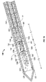
ここで図1〜図4Bを参照して、マイクロ波組織治療システム10が開示される。システム10は、フィードライン60によって電源40と接続されたアンテナアセンブリ100を有するマイクロ波組織治療デバイス20を含む。電源40は、例えばマイクロ波ジェネレータまたはRFジェネレータのような組織治療デバイス20に電気を通じるという意図された目的に対して適切な任意の電力生成デバイスであり得る。マイクロ波組織治療デバイス20は、以下に記述されるように、アンテナアセンブリ100によって、冷却流体または熱散逸流体を循環させるためのメカニズムとして、例えば蠕動ポンプなどのような1つ以上のポンプ80を含み得る。
With reference now to FIGS. 1-4B, a microwave
フィードライン60は、長さが約7フィート〜約10フィートに及び得るが、特定の用途において必要とされる場合、実質的により長くまたはより短くあり得る。フィードライン60は、組織治療デバイス20に電流を伝達することのできる適切な導電性のリードで構成され得る。図2Aに見られる実施形態において、フィードライン60は、内側の導電体64、外側の導電体66、およびその間に挿置された誘電体68を有する同軸のケーブルの周りに配置された細長い部材62を含む。誘導体68は、近位部分60aと遠位部分60bとを含み、内側の導電体64を外側の導電体66から電気的に分離、かつ/または絶縁させる。細長い部材62は、近位端62aと遠位端62bとを含み、任意の導電性の材料または非導電性の材料で形成された任意のスリーブ、チューブ、ジャケットなどであり得る。
The
フィードライン60の近位部分60aは、アンテナアセンブリ100の近位に配置され、電源40と動作可能に接続されるか、または接続可能である。図2Bに見られるように、近位部分60aは、内側の導電体64、外側の導電体66、および誘電体68の近位部分64a、66a、および68aをそれぞれ含み、かつこれらを画定する。フィードライン60の遠位部分60b(図1)は、アンテナアセンブリ100のコンポーネントを形成し、内側の導電体64、外側の導電体66、および誘電体68の遠位部分64b、66b、および68bを含みかつこれらを画定する。あるいは、しかしながら、フィードライン60は、アンテナアセンブリ100から分離可能であり得、かつこれと接続可能であり得ることが想定されている。フィードライン60の構造のさらなる論議のために、2005年1月20日に出願されたTurovskiyらへの共有に係る米国特許第7,311,703号が参照され得る。
A
内側の導電体64および外側の導電体66は各々、導電性の材料または金属、例えばステンレス鋼、銅、または金で少なくとも部分的に形成される。特定の実施形態において、フィードラインの内側の導電体64および外側の導電体66は、適切な導電性の材料でメッキまたは被覆された導電性または非導電性の基板を含み得る。これとは対照的に、誘電体68は、発泡ポリテトラフルオロエチレン(PTFE)、ポリイミド、二酸化ケイ素、またはフッ素ポリマーを含むがこれらに限定されない、内側の導電体64および外側の導電体66を互いから電気的に分離かつ/または絶縁させるために充分な値の誘電値(dielectric value)、および正接損失定数(tangential loss constant)を有する材料から形成される。しかしながら、誘電体68は、内側の導電体64と外側の導電体66との間で所望のインピーダンス値および電気的構成を維持することのできる任意の非導電性の材料で形成され得ることが想定される。さらに、誘電体68は、誘電性の材料の組み合わせから形成され得ることが想定される。
マイクロ波組織治療デバイス10のアンテナアセンブリ100(図1)が、ここで論議される。アンテナアセンブリ100は、近位部分110、遠位または放射部分120、それらの間に配置された密封バリア140、および冷却システム180を含む。
The antenna assembly 100 (FIG. 1) of the microwave
アンテナアセンブリ100の近位部分110は、接続ハブ160とフィードライン60の遠位部分60bとを含む。図4A〜図4Bに見られるように、接続ハブ160は、フィードライン60の遠位部分60b(図1)を受け入れるような構成および大きさとされた第1の導管162、冷却システム180(以下に詳細に論議される)の入口導管182および出口導管184を受け入れるような構成および大きさとされたさらなる導管164a、164b、および入口導管182および出口導管184をそれぞれ受け入れるような構成および大きさとされた、導管164a、164bの内面に形成された1つ以上のアパーチャ166を画定する。接続ハブ160は、ポリマー材料を含むが、これに限定されない任意の適切な材料で形成され得る。
The
誘電体68の遠位部分68bは、誘電体68をそれぞれ貫通する、管腔70およびその周りに配置された一連のチャンネル72a〜72dを画定する。管腔70は、内側の導電体64の遠位部分64bを受け入れるような構成および大きさとされ、チャンネル72a〜72dは、冷却システム180の入口導管182および出口導管184を受け入れるような構成および大きさとされる。管腔70およびチャンネル72a〜72dは、押出し加工、射出成形、またはドリリングを含むが、これらに限定されない任意の適切な製造方法によって誘電体68に形成され得る。
The
図1〜図5Bに関して論議されるマイクロ波組織治療デバイス10の実施形態は、断面構成が実質的に円形である単一の管腔70および4つのチャンネル、すなわちチャンネル72a、72b、72c、および72dを備える誘電体68の遠位部分68bを含むとして例示されるが、誘電体68を貫通する管腔70およびチャンネルの数および/または構成は、所望のインピーダンス、例えば50オームと一致するための空気/ポリマー/冷却流体比率に依存して変化し得ることは理解されるべきである。例えば、管腔70およびチャンネル72a〜72dは、冷却システム180の入口導管182および出口導管184を収容するという意図された目的に対して適切な任意の数で存在し得、例えば図5Cに例示されるような実施形態に見られるような任意の適切な幾何学的構成を示し得る。特に図5Aおよび図5Bを参照して、チャンネル72a〜72dは、誘電体68の遠位部分68bの周囲「P」内に完全にまたは部分的に画定されるように方向付けられ得ることは想定される。
The embodiment of the microwave
図1、図3、および図6をここで参照して、密封バリア140が論議される。密封バリア140は、アンテナアセンブリ100の近位部分110と放射部分120(図3)との間に配置される。密封バリア140は、近位端142および遠位端144(図6)をそれぞれ有し、スナップ嵌め配列、接着剤、またはねじタイプ嵌めを含むが、これらに限定されない任意の適切な態様で、アンテナアセンブリ100の近位部分110と接続され得る。密封バリア140は、それを軸方向に貫通する管腔146および1つ以上のチャンネル148を画定する。管腔146は、内側の導電体64の遠位部分64bを少なくとも部分的に受け入れるように適合され、チャンネル148は、冷却システム180の入口導管182および出口導管184を少なくとも部分的に受け入れるように構成される。内側の導電体64の遠位部分64bおよび冷却システム180の入口導管182および出口導管184が、アンテナアセンブリ100の放射部分120の中に延び得るように、管腔146およびチャンネル148は、誘電体68の遠位部分68bに形成された管腔70およびチャンネル72a〜72d(チャンネル72aおよび72cだけが示される)とそれぞれ整列させられる。
With reference now to FIGS. 1, 3, and 6, the sealing
以下に記述されるように、密封バリア140は、アンテナアセンブリ100の近位部分110の中に流体が逃避することを防止するという意図された目的に対して適切な任意の生体適合性のある材料で形成され得る。密封バリア140は、導電性の材料または非導電性の材料いずれかで形成され得、特性においては、実質的に硬質かまたは実質的に非硬質であり得る。密封バリア140は、流体が内側の導電体64bと外側の導電体66bの両方と接触することを抑制し、このようにして実質的に電気的短絡の可能性を低減する。さらに、密封バリア140は、マイクロ波組織治療デバイス10(図1)のダイポール構造を可能にする誘電性ブレイク(break)として役立つ。
As described below, the sealing
ここで図7Aを参照して、上記で論議されたように、アンテナアセンブリ100の放射部分120は、密封140の遠位端144の近くに配置される。放射部分120は、内側の導電体64の放射セクション122と、放射セクション122の周りに少なくとも部分的に配置されたシース124と、シース124の遠位端124bに支持された間通用部材126とを含む。
Referring now to FIG. 7A, as discussed above, the radiating
内側の導電体64の放射セクション122は、電源40(図1)によって供給されたマイクロ波エネルギーを標的エリアまたは標的組織(図示されず)に送達することに役立つ。放射セクション122は、軸方向の寸法「L」および半径方向の寸法「D」を画定する。当業者によって理解され得るように、放射セクション122の軸方向の寸法および半径方向の寸法を変えることによって、放射セクションを通して標的組織に送達され得るマイクロ波エネルギーの量は、調節または制御され得る。
The radiating
一実施形態において、図7Aに見られるように、内側の導電体64の放射セクション122は、導電性の材料で完全に形成される。代替の実施形態において、図7Bに見られるように、放射セクション122は、導電性の材料で部分的にのみ形成され得る。この実施形態において、放射セクション122は、非導電性の基板152に配置された1つ以上の導電性の表面150を含む。導電性の表面、または表面150は、放射セクション122の中に送達されたエネルギーを集中または分散させるための特定のパターンまたは分配を有し得る。例えば、導電性の表面150は、片側のみに存在し得るか、または放射セクション122の1つの特定のエリアまたは領域に存在し得る。導電性表面150は、基板152と一体的に形成され得るか、または基板152に固定され得るか、もしくは取り外し可能に取り付けられ得る。
In one embodiment, as seen in FIG. 7A, the radiating
図7Aに戻って、シース124は、近位端124aおよび遠位端124bを有し、空洞128を画定するような態様で、放射セクション122の周りに少なくとも部分的に配置される。その近位端124aにおいて、シース124は、当業者によって理解されるように、溶接または接着剤の使用を含むがこれに限定されない任意の適切な態様で、アンテナアセンブリ100の密封バリア140、細長い部材62、または任意の他の適切な表面と固定的に、取り外し可能に、かつ/またはスライド可能に接続され得る。図7Aに見られる実施形態において、シース124の遠位端124bは開放しており、間通用部材126と結合し、その結果空洞128は、間通用部材126と、シース124と、密封バリア140とによって画定されるように構成される。この実施形態において、シース124は、スナップ嵌め配列を介してまたは接着剤の使用によって、図7Aに見られるように、ねじタイプ嵌めを含むが、これに限定されない任意の適切な態様で間通用部材126と接続され得る。
Returning to FIG. 7A, the
別の実施形態において、図7Cに見られるように、シース124の遠位端124bは、閉じられるか、または密封され、その結果空洞128は、シース124と密封バリア140とによってのみ画定される。
In another embodiment, as seen in FIG. 7C, the
さらに別の実施形態において、図7Dに見られるように、シース124の遠位端124bは閉じられ、間通用部材126と一体に形成され、その結果空洞128は、シース124と、密封バリア140と、間通用部材126とによって画定される。
In yet another embodiment, as seen in FIG. 7D, the
さらに別の実施形態において、図7Eに最も良く見られるように、内側の導電体64の放射セクション122の最も遠位の先端130は、シース124の遠位端124bを越えて延びる。この実施形態において、間通用部材126は、放射セクション122と直接的に接続され得る。
In yet another embodiment, as best seen in FIG. 7E, the most
図7Fに見られるように、シース124も、放射セクション122の最も遠位の先端130において、内側の導電体64の放射セクション122と直接的に接続され得る。この実施形態において、間通用部材126は、シース124または放射セクション122いずれかと接続される。
As seen in FIG. 7F, the
前述の実施形態の各々に対して、シース124は、マイクロ波エネルギーの分散を可能にしながら、その中に流体を保持するという意図された目的に対して適切な生体適合性のある材料で形成され得る。シース124は、実質的に硬質のまたは実質的に非硬質の材料で全体が、または部分が形成され得ることが考えられている。例えば、内側の導電体64bが、シース124と電気的に接続される実施形態において、シース124は、ステンレス鋼から形成され得る。さらに、間通用部材126との間の接続は、任意の適切な態様で、解放可能にまたは固定的にアンテナアセンブリ100と結合され得る。
For each of the foregoing embodiments, the
ここで図8を参照して、空洞128は、1つ以上の内部のバッフル部材132、134を含み得、1つ以上の内部のバッフル部材132、134は、放射部分120を、近位領域120a、中間領域120b、および遠位領域120cに分割する。さらに、バッフル部材132、134は、空洞128を近位のセル128a、中間のセル128b、遠位のセル128cに分割し、放射セクション122を第1のセグメント122a、第2のセグメント122b、第3のセグメント122cに分割するように作用する。図8に示される特定の実施形態は、2つのバッフル部材を含むが、放射部分120、空洞128、および放射セクション122を任意の適切な数の領域、セル、およびセグメントにそれぞれ分割するために、任意の適切な数のバッフル部材が使用され得る。
Referring now to FIG. 8, the
空洞128の近位のセル128a、従って、内側の導電体64の放射セクション122の第1のセグメント122aは、第1の軸方向の寸法L1を示し、第1のバッフル部材132と、シース124の近位端124aが密封バリア140と出会う場所とによって画定される。空洞128の中間のセル128b、従って、放射セクション122の第2のセグメント122bは、第2の軸方向の寸法L2を示し、第1のバッフル部材132および第2のバッフル部材134の場所によって画定される。空洞128の遠位のセル128cおよび放射セクション122の第3のセグメント122cは、第3の軸方向の寸法L3を示し、第2のバッフル部材134およびシース124の遠位端126cの場所によって画定される。
The
第1のバッフル部材132および第2のバッフル部材134はそれぞれ、シース124によって画定された空洞128の3つのセル128a、128b、128cの境界を部分的に画定することに役立つばかりではなく、本明細書の以下にさらに詳細に論議されるように、放射部分120の近位領域120a、中間領域120b、および遠位領域120cの各々全体にわたって循環し得る流体または流体(複数)(図示されず)の任意の混合を防止することにも役立つ。
The
図8を引続き参照して、アンテナアセンブリ100の放射部分120の遠位領域120cは、組織の治療または切除の間、能動加熱のエリアを含み得る。従って、最適のエネルギー送達を維持するために、および組織の最適の温熱療法を維持するために、遠位領域120cの温度が過度に高い温度に達することを防止することが望ましい。中間領域120bも、オーム加熱および遠位領域120cからの伝導加熱により熱くなり得る。中間領域120bは、標的の部位を取り囲む組織と接触し得るので、実行される外科的処置の性質に依存して、特定の温度プロファイルを達成することを可能にすることが望ましくあり得る。
With continued reference to FIG. 8, the
例として、挿入路の凝固が望ましくあり得る場合、臨床医は、放射部分120の中間領域120bが、挿入路において凝固効果を作成することができる特定の所定の温度を達成し得ることを欲することがあり得る。他の適用において、望ましくない効果から周囲の敏感な組織構造を保護するために、中間領域120bの温度が特定の閾値レベルを超えて上昇することを防止することも望ましくあり得る。
As an example, if coagulation of the insertion path can be desirable, the clinician wants the
使用の間、放射部分120の近位領域120aはまた、患者の皮膚または組織と接触し得る。近位領域120aもオーム加熱および/または伝導加熱を受け得るとき、特に経皮的または腹腔鏡的処置において、患者の組織に対する任意の望ましくない効果を和らげるかまたは実質的に防止するために、近位領域120aの温度を特定の温度よりも低く維持することが望ましくあり得る。例えば、病変の位置が組織内深く位置する場合のような他の処置においては、挿入路の凝固を可能にするために、近位領域120aが加熱されることを可能にすることが望ましくあり得る。
During use, the
図1もここで参照して、本開示の冷却システム180の特定のコンポーネントおよび特徴は、アンテナアセンブリ100の半径方向の寸法すなわち横方向の寸法を低減し、それによって、アンテナアセンブリ100の性能を可能性として向上させる。しかしながら、アンテナアセンブリ100の寸法を低減させることには、より大きくより従来型のアンテナおよびより低いエネルギーレベルを使用することによって達成され得る治療効果と同じ治療効果を達成するために、アンテナアセンブリ100を通って流れるエネルギーの量の増加が必然的に伴う。本開示の冷却システム180は、アンテナアセンブリ100を通って流れるエネルギーの増加した量が、例えばマイクロ波組織治療デバイス20の損失、過熱、および故障の可能性のような悪い結果を有する可能性を低減し、かかる結果が生じた場合、その影響に対処する。
Referring now also to FIG. 1, certain components and features of the
ここで図1および図9を参照して、冷却システム180が論議される。冷却システム180は、アンテナアセンブリ100の放射部分120(図1)全体にわたって、継続的または断続的のいずれかで流体「F」を循環させるように適合される。流体「F」は液体、例えば水、食塩水、液体クロロジフルオロメタン、例えばMinnesota Mining and Manufacturing Company(3M)、St.Paul、Minnesota、USAによって商業的に配給されるFluorinert(登録商標)のようなパーフルオロカーボン、またはそれらの任意の組み合わせであり得る。様々な実施形態において、例えば空気、亜酸化窒素、窒素、二酸化炭素、その他のような気体が、前記の液体のうちの任意のものに対する代替として、またはこれと共に利用され得る。流体「F」の組成は、所望の冷却速度およびフィードライン60の所望のインピーダンスに依存して、変えられ得る。
Referring now to FIGS. 1 and 9, the
冷却システム180は、近位端182a(図1)および遠位端182b(図9)を有する入口導管182と、近位端184a(図1)および遠位端184b(図9)を有する出口導管184とを含む。入口導管182および出口導管184の近位端182a、184aはそれぞれ、ポンプ80(図1)と接続され、これと流体連通し、入口導管182および出口導管184の遠位端182b、184bはそれぞれ、シース124によって画定された空洞128(図9)と流体連通する。入口導管182および出口導管184はそれぞれ、ポンプ80と協働して作用し、空洞128を通して流体「F」を循環させ、それによって内側の導電体64(たとえば図2Aを参照)の放射セクション122を冷却する。冷却システム180は、空洞128全体にわたって散逸流体「F」を循環させるという意図された目的に対して適切な任意の数の入口導管182および出口導管184を含み得る。
The
図3および図4A〜図4Bをさらに参照して、入口導管182および出口導管184は、ポンプ80から延びて、接続ハブ160の導管164a、164bに入る。入口導管182および出口導管184は、細長い部材62を通り、接続ハブ160に形成されたアパーチャ166を通って、誘電体68の遠位部分68bに形成されたチャンネル72a〜72dに入る。入口導管182および出口導管184は、密封バリア140に形成されたチャンネル148(図9)を遠位方向に貫通し、アンテナアセンブリ100の放射部分120(図1)の中に入り、それによって放射部分120内での流体「F」の循環を容易にする。
With further reference to FIGS. 3 and 4A-4B,
例えば、誘電体68を貫通する入口導管182および出口導管184のような冷却システム180を含むことは、アンテナアセンブリ100の周りに位置決めされた外部の冷却チャンバを含む冷却システムとは対照的に、大きさの低減という利益を作成する。つまり、外部の冷却チャンバは必要ではないようにすることにより、外側の導電体66bの横方向の外側寸法は、アンテナアセンブリ100の横方向の外側寸法となる。これによって、アンテナアセンブリ100の全体的な横方向の寸法を増加させることなく、損失効果を低減するより大きな内側導管64bおよび外側導管66bを使用することが可能となる。
For example, including a
図10に見られるように、一実施形態において、入口導管182および出口導管184の数は、アンテナアセンブリ100の放射部分120の領域、セグメント、およびセル、内側導電体64の放射セクション122、ならびに空洞128それぞれの数に対応する。特に、入口導管182’および出口導管184’は、空洞128の近位のセル128a全体にわたって流体「F」を循環させ、その結果流体「F」は、放射セクション122の近位のセグメント122aと接触し得、それによってアセンブリ100の放射部分120の近位領域120aを冷却し得る。同様の方法で、入口導管182’’および出口導管184’’は、空洞128の中間のセル128b全体にわたって流体「F」を循環させ、その結果流体「F」は、放射セクション122の中間のセグメント122bと接触し得、それによってアンテナアセンブリ100の放射部分120の中間領域120bを冷却し得、入口導管182’’’および出口導管184’’’は、空洞128の遠位のセル128c全体にわたって流体「F」を循環させ、その結果流体「F」は、放射セクション122の遠位のセグメント122cと接触し得、それによってアンテナアセンブリ100の放射部分120の遠位領域120cを冷却し得る。図10は、流体「F」と接触する各セル128a〜128cを示しているが、本開示は、流体「F」がセル128a〜128cのうちの1つ以上を通って循環しないことがあり得る代替も想定している。
As can be seen in FIG. 10, in one embodiment, the number of
図10をなおも参照して、流体「F」は、入口導管182’を通って、すなわち矢印「A」の方向に、近位のセル128aに入ると、流体「F」は、内側の導電体64の放射セクション122の近位のセグメント122aと直接的に接触し、その直接的対流冷却が可能となる。流体「F」が、近位のセグメント122aを冷却すると、ポンプ80(図1)は、出口導管184’を通して矢印「B」の方向に近位のセル128aから流体「F」を除去する。そのようにすることで、アンテナアセンブリ100の動作の間に、近位のセグメント122aによって生成された熱は、調節かつ/または散逸され得る。従って、放射部分120の近位領域120aの温度は制御され得る。
Still referring to FIG. 10, when fluid “F” enters
近位のセル128aに対すると同じように、流体「F」は、入口導管182’’および出口導管184’’をそれぞれ通してポンプ80(図1)によって、中間のセル128bの中に出入りして循環し得、それによってアンテナアセンブリ100の動作の間に、中間のセグメント122bによって生成された熱を流体「F」によって散逸させる。
As with
同様に、流体「F」は、入口導管182’’’および出口導管184’’’それぞれを通してポンプ80(図1)によって遠位のセル128cに出入りして循環し得、それによってアンテナアセンブリ100の動作の間に、遠位のセグメント122cによって生成された熱を流体「F」によって散逸させる。
Similarly, fluid “F” may circulate into and out of
空洞128の近位のセル128aを通して流体「F」を循環させるためには、入口導管182’および出口導管184’は、密封バリア140の対応するチャンネル148(図6、図9)を通る。中間のセル128bを通して流体「F」を循環させるためには、入口導管182’’および出口導管184’’は、チャンネル148、および第1のバッフル部材132のアパーチャ136を通る。遠位のセル128cを通して流体「F」を循環させるためには、入口導管182’’’および出口導管184’’’は、チャンネル148、第1のバッフル部材132のアパーチャ136、中間のセル128bを通り、そして最終的に第2のバッフル部材134のアパーチャ136を通る。
In order to circulate fluid “F” through
密封バリア140、第1のバッフル部材132、および第2のバッフル部材134は各々、チャンネル148およびアパーチャ136とそれぞれ関連付けられた密封部材(図示されず)含み得、流体「F」が、空洞128のセル128a〜128cの間で混合することを実質的に防止し、密封部材は、シール、ガスケットなどを含むが、これらに限定されない、この意図された目的に対して適切な任意の部材であり得る。密封部材は、ポリマー材料を含むがこれに限定されない、任意の適切な材料で形成され得る。
図10をなおも参照して、内側の導電体64(例えば図2Aを参照)の放射セクション122(図9)の個々のセグメント122a〜122c内、およびアンテナアセンブリ100の放射部分120の対応する領域120a〜120cにおける加熱および温度調節を制御することが望ましいので、空洞128内でのバッフル部材132、134の軸方向の位置は、所望または必要に応じて変わり得、その結果空洞128の近位、中間、および遠位のセル128a〜128cの軸方向の寸法L1、L2およびL3も、変わり得る。空洞128の特定のセルの軸方向の長さを変えると、そのセルの全体的な容積が変わり得、その結果、そこを循環する流体「F」の容積も変わり得る。当業者によって理解され得るように、流体「F」の容積が増加すると、その領域の温度が下がるという点で、空洞128の特定のセル内の流体「F」の容積と放射部分120の対応する領域の温度との間には、逆の関係が存在する。
Still referring to FIG. 10, within
バッフル部材132、134は、空洞128内の適切な点、または所望の点に位置し得る。一実施形態において、バッフル部材132、134は、近位、中間、および遠位のセル128a〜128cの第1、第2および第3の軸方向の寸法、L1、L2およびL3が実質的に等価になるように位置決めされ得る。別の実施形態において、バッフル部材132、134は、近位のセル128aの第1の軸方向の寸法L1が、中間のセル128bおよび遠位のセル128cの第2の軸方向の寸法L2および第3の軸方向の寸法L3よりも大きくなるように位置決めされる。さらに別の実施形態において、バッフル部材132、134は、遠位のセル128cの第3の軸方向の寸法L3が、近位のセル128aおよび中間のセル128bの第1の軸方向の寸法L1および第2の軸方向の寸法L2よりも大きくなるように位置決めされ得る。代替の実施形態において、バッフル部材132、134は、空洞128の全体的な容積が、任意の適切な態様で、その任意の個々のセルの間で分配され得るように位置付けられ得る。
The
図11をここで参照して、別の実施形態において、空洞128の近位のセル128a、中間のセル128b、および遠位のセル128cは、第1の半径方向の寸法D1、第2の半径方向の寸法D2、および第3の半径方向の寸法D3を画定する。示されるように、半径方向の寸法D1は、半径方向の寸法D2よりも大きく、半径方向の寸法D2は、半径方向の寸法D3よりも大きい。しかしながら、第1の半径方向の寸法D1、第2の半径方向の寸法D2、および第3の半径方向の寸法D3は、実質的に等価であることもあり得る。
Referring now to FIG. 11, in another embodiment, the
近位のセル128a、中間のセル128b、および遠位のセル128cの半径方向の寸法D1、D2、D3は任意の適切な態様で変えられ得、それによってそれらの容積を調節し、従って、それらを通って循環し得る流体「F」の容積を調節する。空洞128の各セル128a〜128cを通って循環する流体「F」の容積を変えることによって、アンテナアセンブリ100の放射部分120の各対応する領域120a〜120cの温度は、上述のように実質的に調節され得る。
The radial dimensions D 1 , D 2 , D 3 of the
図12に見られるように、別の実施形態において、空洞128は半径方向の寸法Dを画定し、半径方向の寸法Dは、その軸方向の長さにわたって連続的に減少する態様で変えられ、その結果概ね先細りのプロファイルが示される。この実施形態に示される先細りのプロファイルは、本明細書の上に開示された実施形態のうちの任意のものにも適用され得る。
As seen in FIG. 12, in another embodiment, the
図13は、さらに別の実施形態を例示し、この別の実施形態においては、アンテナアセンブリ100は、内側の導電体64の放射セクション122のセグメント122a〜122cに適合され、結合され、または動作可能に接続された1つ以上の温度センサ190を含む。温度センサ190は、放射部分120の領域120a〜120cの温度の任意の変動をモニタするために使用され得る。組織に対する過熱および/または任意の意図されない治療効果に対して警戒するために、放射部分120、および/または放射部分120と接触し得る組織の温度をモニタすることが望ましくあり得る。マイクロ波が放射部分の周りの組織を治療または切除するために使用される場合に、これは特に有用な適用であり得る。代替の実施形態において、温度センサ190は、シース124を含むが、これに限定されず、任意の適切な場所で、アンテナアセンブリ100に適合、結合、動作可能に接続、またはこの中に組み込まれ得る。温度センサ190は、任意の従来の手段、例えば接着剤を使用して、シース124の上に、またはこの中に位置し得る。温度センサ190は、もしあるとすれば、1つ以上バッフル部材、例えばバッフル部材132、134の上にも位置し得る。温度センサ190は、電源40(図1)との電気的接続に対して適合されるように構成され得る。
FIG. 13 illustrates yet another embodiment, in which the
温度センサ190は、半導体ベースのセンサ、サーミスタ、熱電対、または当業者によって適切と考えられる他の温度センサであり得る。独立した温度モニタ(図示されず)が、温度センサに接続され得るか、または電源40(図1)が、例えば米国特許第5,954,719号に記述されたもののような統合型温度モニタリング回路(図示されず)を含み得、アンテナアセンブリ100に供給されるマイクロ波電力出力を調整し得る。他の生理学的な信号、例えばEKGも、当業者に周知のさらなる医療器具によってモニタされ得、かかるデータは、アンテナアセンブリ100に送達されるマイクロ波エネルギーを制御するために適用される。
The
例えばマイクロプロセッサを備えたフィードバックコントローラのような閉ループ制御メカニズムは、例えばマイクロ波エネルギーのようなエネルギーの標的組織への送達を、温度センサ190によって測定された温度に基づいて制御するために実装され得る。
A closed loop control mechanism, such as a feedback controller with a microprocessor, for example, can be implemented to control the delivery of energy, such as microwave energy, to the target tissue based on the temperature measured by the
上の記述、開示、および特徴は、限定するものとして解釈されるべきではなく、特定の実施形態の単なる例として解釈されるべきである。従って、本開示は、記述された正確な実施形態に限定されず、様々な他の変更および修正が、本開示の範囲または精神から逸脱することなくそれらの実施形態の中で当業者によってなされると理解されるべきである。さらに、一実施形態と共に例示または記述された特徴は、別の実施形態の特徴と組み合わせられ得、かかる修正および変更も本開示の範囲内に含まれることが意図されていることを当業者は理解する。 The above description, disclosure, and features should not be construed as limiting, but merely as exemplifications of particular embodiments. Accordingly, the present disclosure is not limited to the precise embodiments described, and various other changes and modifications can be made by those skilled in the art within those embodiments without departing from the scope or spirit of the disclosure. Should be understood. Further, those skilled in the art will appreciate that the features illustrated or described with one embodiment may be combined with the features of another embodiment, and that such modifications and changes are intended to be included within the scope of the present disclosure. To do.
Claims (12)
近位端および遠位端を有するアンテナアセンブリであって、該アンテナアセンブリは、
外側の導電体と、
該外側の導電体内に配置された誘電材料であって、該誘電材料の少なくとも一部分は、管腔および長手方向に延びる少なくとも1つのチャンネルを画定する、誘電材料と、
遠位の放射セクションを有する内側の導電体であって、該内側の導電体の少なくとも一部分は、該誘電材料の該管腔内に少なくとも部分的に配置された、内側の導電体と、
該外側の導電体の遠位端の近くに配置された密封バリアと、
該密封バリアの近くに配置された放射部分であって、該放射部分は、該内側導電体の該遠位の放射セクションと該内側の導電体の該遠位の放射セクションの周りに少なくとも部分的に配置されたシースとを含み、その結果少なくとも1つの空洞が該放射部分の中に画定される、放射部分と
を含む、アンテナアセンブリと、
入口導管と出口導管とを含む冷却システムであって、該入口導管および該出口導管は、該誘電材料の該長手方向に延びる少なくとも1つのチャンネル内に少なくとも部分的に配置され、かつ流体を循環させるように構成され、該入口導管および該出口導管は、該少なくとも1つ空洞と流体連通し、その結果該内側の導電体の該放射セクションの少なくとも一部分は、該流体と少なくとも部分的に流体接触する、冷却システムと
を備えている、デバイス。 A microwave tissue treatment device,
An antenna assembly having a proximal end and a distal end, the antenna assembly comprising:
An outer conductor,
A dielectric material disposed within the outer conductor, wherein at least a portion of the dielectric material defines a lumen and at least one channel extending longitudinally;
An inner conductor having a distal radiating section, wherein at least a portion of the inner conductor is at least partially disposed within the lumen of the dielectric material;
A sealing barrier disposed near the distal end of the outer conductor;
A radiating portion disposed near the sealing barrier, the radiating portion at least partially around the distal radiating section of the inner conductor and the distal radiating section of the inner conductor An antenna assembly comprising: a radiating portion including: a radiating portion, wherein the radiating portion is defined in the radiating portion;
A cooling system including an inlet conduit and an outlet conduit, wherein the inlet conduit and the outlet conduit are at least partially disposed in the longitudinally extending channel of the dielectric material and circulate fluid. The inlet conduit and the outlet conduit are in fluid communication with the at least one cavity so that at least a portion of the radiating section of the inner conductor is at least partially in fluid contact with the fluid. A device comprising a cooling system.
Applications Claiming Priority (2)
| Application Number | Priority Date | Filing Date | Title |
|---|---|---|---|
| US3319608P | 2008-03-03 | 2008-03-03 | |
| US61/033,196 | 2008-03-03 |
Publications (2)
| Publication Number | Publication Date |
|---|---|
| JP2009207898A true JP2009207898A (en) | 2009-09-17 |
| JP5399741B2 JP5399741B2 (en) | 2014-01-29 |
Family
ID=40584703
Family Applications (1)
| Application Number | Title | Priority Date | Filing Date |
|---|---|---|---|
| JP2009048620A Expired - Fee Related JP5399741B2 (en) | 2008-03-03 | 2009-03-02 | Internally cooled percutaneous microwave ablation probe |
Country Status (4)
| Country | Link |
|---|---|
| US (2) | US8965536B2 (en) |
| EP (2) | EP2098184B1 (en) |
| JP (1) | JP5399741B2 (en) |
| ES (1) | ES2368779T3 (en) |
Cited By (18)
| Publication number | Priority date | Publication date | Assignee | Title |
|---|---|---|---|---|
| JP2012187405A (en) * | 2011-03-09 | 2012-10-04 | Vivant Medical Inc | System for thermal-feedback-controlled rate of fluid flow to fluid-cooled antenna assembly and method of directing energy to tissue using same |
| JP2013525075A (en) * | 2010-05-03 | 2013-06-20 | ニューウェーブ メディカル,インコーポレイテッド | Energy delivery system and use thereof |
| JP2015521895A (en) * | 2012-06-29 | 2015-08-03 | コヴィディエン リミテッド パートナーシップ | Microwave antenna probe |
| JP2016163758A (en) * | 2011-12-21 | 2016-09-08 | ニューウェーブ メディカル, インコーポレイテッドNeuwave Medical, Inc. | Energy supply system |
| JP2016172022A (en) * | 2011-01-05 | 2016-09-29 | コビディエン エルピー | Energy transfer device with flexible fluid cooling shaft, inflow / outflow joints suitable for use therewith and system including them |
| US9566115B2 (en) | 2009-07-28 | 2017-02-14 | Neuwave Medical, Inc. | Energy delivery systems and uses thereof |
| US9770294B2 (en) | 2011-01-05 | 2017-09-26 | Covidien Lp | Energy-delivery devices with flexible fluid-cooled shaft, inflow/outflow junctions suitable for use with same, and systems including same |
| JP2017529145A (en) * | 2014-08-26 | 2017-10-05 | コヴィディエン リミテッド パートナーシップ | Microwave ablation catheter assembly, method for electrosurgical treatment of target tissue, and microwave ablation system |
| US10123837B2 (en) | 2011-01-05 | 2018-11-13 | Covidien Lp | Energy-delivery devices with flexible fluid-cooled shaft, inflow / outflow junctions suitable for use with same, and systems including same |
| JP2018538058A (en) * | 2015-12-07 | 2018-12-27 | クレオ・メディカル・リミテッドCreo Medical Limited | An electrosurgical instrument for emitting microwave energy and draining liquid at a treatment site |
| US10335230B2 (en) | 2011-03-09 | 2019-07-02 | Covidien Lp | Systems for thermal-feedback-controlled rate of fluid flow to fluid-cooled antenna assembly and methods of directing energy to tissue using same |
| US10363092B2 (en) | 2006-03-24 | 2019-07-30 | Neuwave Medical, Inc. | Transmission line with heat transfer ability |
| US10376314B2 (en) | 2006-07-14 | 2019-08-13 | Neuwave Medical, Inc. | Energy delivery systems and uses thereof |
| US10531917B2 (en) | 2016-04-15 | 2020-01-14 | Neuwave Medical, Inc. | Systems and methods for energy delivery |
| US10952792B2 (en) | 2015-10-26 | 2021-03-23 | Neuwave Medical, Inc. | Energy delivery systems and uses thereof |
| US11389235B2 (en) | 2006-07-14 | 2022-07-19 | Neuwave Medical, Inc. | Energy delivery systems and uses thereof |
| US11672596B2 (en) | 2018-02-26 | 2023-06-13 | Neuwave Medical, Inc. | Energy delivery devices with flexible and adjustable tips |
| US11832879B2 (en) | 2019-03-08 | 2023-12-05 | Neuwave Medical, Inc. | Systems and methods for energy delivery |
Families Citing this family (58)
| Publication number | Priority date | Publication date | Assignee | Title |
|---|---|---|---|---|
| US9622813B2 (en) | 2007-11-01 | 2017-04-18 | Covidien Lp | Method for volume determination and geometric reconstruction |
| US8280525B2 (en) | 2007-11-16 | 2012-10-02 | Vivant Medical, Inc. | Dynamically matched microwave antenna for tissue ablation |
| US8945111B2 (en) | 2008-01-23 | 2015-02-03 | Covidien Lp | Choked dielectric loaded tip dipole microwave antenna |
| US8435237B2 (en) | 2008-01-29 | 2013-05-07 | Covidien Lp | Polyp encapsulation system and method |
| US8965536B2 (en) | 2008-03-03 | 2015-02-24 | Covidien Lp | Intracooled percutaneous microwave ablation probe |
| US9949794B2 (en) | 2008-03-27 | 2018-04-24 | Covidien Lp | Microwave ablation devices including expandable antennas and methods of use |
| US8192427B2 (en) | 2008-06-09 | 2012-06-05 | Tyco Healthcare Group Lp | Surface ablation process with electrode cooling methods |
| US8211098B2 (en) | 2008-08-25 | 2012-07-03 | Vivant Medical, Inc. | Microwave antenna assembly having a dielectric body portion with radial partitions of dielectric material |
| US8251987B2 (en) | 2008-08-28 | 2012-08-28 | Vivant Medical, Inc. | Microwave antenna |
| US8403924B2 (en) | 2008-09-03 | 2013-03-26 | Vivant Medical, Inc. | Shielding for an isolation apparatus used in a microwave generator |
| US8202270B2 (en) | 2009-02-20 | 2012-06-19 | Vivant Medical, Inc. | Leaky-wave antennas for medical applications |
| US8197473B2 (en) | 2009-02-20 | 2012-06-12 | Vivant Medical, Inc. | Leaky-wave antennas for medical applications |
| US9277969B2 (en) | 2009-04-01 | 2016-03-08 | Covidien Lp | Microwave ablation system with user-controlled ablation size and method of use |
| US8463396B2 (en) | 2009-05-06 | 2013-06-11 | Covidien LLP | Power-stage antenna integrated system with high-strength shaft |
| US8292881B2 (en) | 2009-05-27 | 2012-10-23 | Vivant Medical, Inc. | Narrow gauge high strength choked wet tip microwave ablation antenna |
| USD634010S1 (en) | 2009-08-05 | 2011-03-08 | Vivant Medical, Inc. | Medical device indicator guide |
| US9031668B2 (en) * | 2009-08-06 | 2015-05-12 | Covidien Lp | Vented positioner and spacer and method of use |
| US8355803B2 (en) * | 2009-09-16 | 2013-01-15 | Vivant Medical, Inc. | Perfused core dielectrically loaded dipole microwave antenna probe |
| US8394087B2 (en) * | 2009-09-24 | 2013-03-12 | Vivant Medical, Inc. | Optical detection of interrupted fluid flow to ablation probe |
| US8343145B2 (en) * | 2009-09-28 | 2013-01-01 | Vivant Medical, Inc. | Microwave surface ablation using conical probe |
| US8568401B2 (en) | 2009-10-27 | 2013-10-29 | Covidien Lp | System for monitoring ablation size |
| US8469953B2 (en) * | 2009-11-16 | 2013-06-25 | Covidien Lp | Twin sealing chamber hub |
| US8968288B2 (en) * | 2010-02-19 | 2015-03-03 | Covidien Lp | Ablation devices with dual operating frequencies, systems including same, and methods of adjusting ablation volume using same |
| USD673685S1 (en) | 2010-09-08 | 2013-01-01 | Vivant Medical, Inc. | Microwave device spacer and positioner with arcuate slot |
| US8945144B2 (en) | 2010-09-08 | 2015-02-03 | Covidien Lp | Microwave spacers and method of use |
| US8968289B2 (en) | 2010-10-22 | 2015-03-03 | Covidien Lp | Microwave spacers and methods of use |
| US9119647B2 (en) * | 2010-11-12 | 2015-09-01 | Covidien Lp | Apparatus, system and method for performing an electrosurgical procedure |
| US8932281B2 (en) | 2011-01-05 | 2015-01-13 | Covidien Lp | Energy-delivery devices with flexible fluid-cooled shaft, inflow/outflow junctions suitable for use with same, and systems including same |
| CA2832593A1 (en) | 2011-04-08 | 2012-07-18 | Joseph D. Brannan | Flexible microwave catheters for natural or artificial lumens |
| US9579150B2 (en) * | 2011-04-08 | 2017-02-28 | Covidien Lp | Microwave ablation instrument with interchangeable antenna probe |
| US9375274B2 (en) | 2012-01-05 | 2016-06-28 | Covidien Lp | Ablation systems, probes, and methods for reducing radiation from an ablation probe into the environment |
| US9113930B2 (en) | 2012-01-05 | 2015-08-25 | Covidien Lp | Ablation systems, probes, and methods for reducing radiation from an ablation probe into the environment |
| US9119648B2 (en) | 2012-01-06 | 2015-09-01 | Covidien Lp | System and method for treating tissue using an expandable antenna |
| US9113931B2 (en) | 2012-01-06 | 2015-08-25 | Covidien Lp | System and method for treating tissue using an expandable antenna |
| CA2877571A1 (en) | 2012-06-22 | 2013-12-27 | Covidien Lp | Microwave thermometry for microwave ablation systems |
| US9370398B2 (en) | 2012-08-07 | 2016-06-21 | Covidien Lp | Microwave ablation catheter and method of utilizing the same |
| US9743975B2 (en) | 2012-10-02 | 2017-08-29 | Covidien Lp | Thermal ablation probe for a medical device |
| CN103006321B (en) * | 2012-11-08 | 2016-04-20 | 南京维京九洲医疗器械研发中心 | A kind of water cooling microwave ablation aciculiform antenna |
| US9101344B2 (en) | 2013-03-15 | 2015-08-11 | Covidien Lp | Recirculating cooling system for energy delivery device |
| US9682190B2 (en) | 2013-03-15 | 2017-06-20 | Covidien Lp | Recirculating cooling system for energy delivery device |
| JP6363169B2 (en) | 2013-03-29 | 2018-07-25 | コビディエン エルピー | Step-down coaxial microwave ablation applicator and method for manufacturing the same |
| US10813691B2 (en) | 2014-10-01 | 2020-10-27 | Covidien Lp | Miniaturized microwave ablation assembly |
| US10660691B2 (en) | 2015-10-07 | 2020-05-26 | Angiodynamics, Inc. | Multiple use subassembly with integrated fluid delivery system for use with single or dual-lumen peristaltic tubing |
| US10813692B2 (en) | 2016-02-29 | 2020-10-27 | Covidien Lp | 90-degree interlocking geometry for introducer for facilitating deployment of microwave radiating catheter |
| US11369434B2 (en) | 2016-06-22 | 2022-06-28 | Covidien Lp | Systems and methods for determining the status of a fluid-cooled microwave ablation system |
| US11197715B2 (en) | 2016-08-02 | 2021-12-14 | Covidien Lp | Ablation cable assemblies and a method of manufacturing the same |
| US11065053B2 (en) | 2016-08-02 | 2021-07-20 | Covidien Lp | Ablation cable assemblies and a method of manufacturing the same |
| US10376309B2 (en) | 2016-08-02 | 2019-08-13 | Covidien Lp | Ablation cable assemblies and a method of manufacturing the same |
| JP7049326B2 (en) | 2016-10-04 | 2022-04-06 | アヴェント インコーポレイテッド | Cooled RF probe |
| EP3573561B1 (en) * | 2017-01-26 | 2023-05-31 | Broncus Medical Inc. | Bronchoscopic-based microwave ablation system and method |
| US11071586B2 (en) | 2017-06-05 | 2021-07-27 | Covidien Lp | Cooling systems for energy delivery devices |
| GB2575485A (en) * | 2018-07-12 | 2020-01-15 | Creo Medical Ltd | Electrosurgical instrument |
| US11737823B2 (en) | 2018-10-31 | 2023-08-29 | Intuitive Surgical Operations, Inc. | Antenna systems and methods of use |
| US11280863B2 (en) * | 2018-11-02 | 2022-03-22 | Intuitive Surgical Operations, Inc. | Coiled antenna with fluid cooling |
| US11135010B2 (en) * | 2019-05-24 | 2021-10-05 | Precision Microwave Inc. | Minimally invasive microwave ablation device |
| CN114569242B (en) * | 2022-03-05 | 2024-08-13 | 南京德文医学科技有限公司 | Non-water-cooled microwave ablation catheter |
| USD1084316S1 (en) | 2023-11-20 | 2025-07-15 | Angiodynamics, Inc. | Ferrule |
| US20250281235A1 (en) * | 2024-03-08 | 2025-09-11 | MustWave Medical Inc. | Water-coolled flexible microwave ablation probe |
Citations (4)
| Publication number | Priority date | Publication date | Assignee | Title |
|---|---|---|---|---|
| JPH10230017A (en) * | 1997-02-19 | 1998-09-02 | Olympus Optical Co Ltd | Intracavitary applicator for hypothermia |
| JP2002045370A (en) * | 2000-08-02 | 2002-02-12 | Olympus Optical Co Ltd | Device for treatment |
| US20060276780A1 (en) * | 2004-04-29 | 2006-12-07 | Brace Christopher L | Air-core microwave ablation antennas |
| JP2007532024A (en) * | 2003-07-18 | 2007-11-08 | ビバント メディカル インコーポレイテッド | Apparatus and method for cooling a microwave antenna |
Family Cites Families (28)
| Publication number | Priority date | Publication date | Assignee | Title |
|---|---|---|---|---|
| US5275597A (en) * | 1992-05-18 | 1994-01-04 | Baxter International Inc. | Percutaneous transluminal catheter and transmitter therefor |
| US5556377A (en) * | 1992-08-12 | 1996-09-17 | Vidamed, Inc. | Medical probe apparatus with laser and/or microwave monolithic integrated circuit probe |
| US5348554A (en) | 1992-12-01 | 1994-09-20 | Cardiac Pathways Corporation | Catheter for RF ablation with cooled electrode |
| US5431168A (en) * | 1993-08-23 | 1995-07-11 | Cordis-Webster, Inc. | Steerable open-lumen catheter |
| US5683384A (en) | 1993-11-08 | 1997-11-04 | Zomed | Multiple antenna ablation apparatus |
| WO1996034571A1 (en) | 1995-05-04 | 1996-11-07 | Cosman Eric R | Cool-tip electrode thermosurgery system |
| US6575969B1 (en) * | 1995-05-04 | 2003-06-10 | Sherwood Services Ag | Cool-tip radiofrequency thermosurgery electrode system for tumor ablation |
| US5810804A (en) * | 1995-08-15 | 1998-09-22 | Rita Medical Systems | Multiple antenna ablation apparatus and method with cooling element |
| US6059780A (en) * | 1995-08-15 | 2000-05-09 | Rita Medical Systems, Inc. | Multiple antenna ablation apparatus and method with cooling element |
| US5954719A (en) | 1996-12-11 | 1999-09-21 | Irvine Biomedical, Inc. | System for operating a RF ablation generator |
| US6974463B2 (en) * | 1999-02-09 | 2005-12-13 | Innercool Therapies, Inc. | System and method for patient temperature control employing temperature projection algorithm |
| EP1056405A1 (en) * | 1998-02-27 | 2000-12-06 | Curon Medical, Inc. | Apparatus to electrosurgically treat esophageal sphincters |
| US6136014A (en) | 1998-09-01 | 2000-10-24 | Vivant Medical, Inc. | Percutaneous tissue removal device |
| DE60044531D1 (en) | 1999-06-25 | 2010-07-22 | Vahid Saadat | TISSUE TREATMENT DEVICE |
| CA2409716C (en) * | 2000-05-16 | 2010-11-30 | Atrionix, Inc. | Apparatus and method incorporating an ultrasound transducer onto a delivery member |
| EP1429676A4 (en) * | 2001-09-19 | 2007-10-24 | Urologix Inc | Microwave ablation device |
| EP1465701A4 (en) * | 2002-01-15 | 2008-08-13 | Univ California | SYSTEM AND METHOD FOR DIRECTIONAL ULTRASONIC THERAPY OF SKELETAL JOINTS |
| US20040158237A1 (en) * | 2003-02-11 | 2004-08-12 | Marwan Abboud | Multi-energy ablation station |
| US20050245920A1 (en) * | 2004-04-30 | 2005-11-03 | Vitullo Jeffrey M | Cell necrosis apparatus with cooled microwave antenna |
| US7282049B2 (en) * | 2004-10-08 | 2007-10-16 | Sherwood Services Ag | Electrosurgical system employing multiple electrodes and method thereof |
| GB2434314B (en) * | 2006-01-03 | 2011-06-15 | Microsulis Ltd | Microwave applicator with dipole antenna |
| US20070078454A1 (en) * | 2005-09-30 | 2007-04-05 | Mcpherson James W | System and method for creating lesions using bipolar electrodes |
| EP1998698B1 (en) | 2006-03-24 | 2020-12-23 | Neuwave Medical, Inc. | Transmission line with heat transfer ability |
| US7769469B2 (en) * | 2006-06-26 | 2010-08-03 | Meridian Medical Systems, Llc | Integrated heating/sensing catheter apparatus for minimally invasive applications |
| PL2043543T3 (en) | 2006-07-14 | 2020-03-31 | Neuwave Medical, Inc. | Energy delivery system |
| US10376314B2 (en) * | 2006-07-14 | 2019-08-13 | Neuwave Medical, Inc. | Energy delivery systems and uses thereof |
| US8211099B2 (en) * | 2007-01-31 | 2012-07-03 | Tyco Healthcare Group Lp | Thermal feedback systems and methods of using the same |
| US8965536B2 (en) | 2008-03-03 | 2015-02-24 | Covidien Lp | Intracooled percutaneous microwave ablation probe |
-
2009
- 2009-02-27 US US12/395,034 patent/US8965536B2/en active Active
- 2009-03-02 JP JP2009048620A patent/JP5399741B2/en not_active Expired - Fee Related
- 2009-03-03 EP EP09003029A patent/EP2098184B1/en not_active Not-in-force
- 2009-03-03 EP EP11164913.3A patent/EP2359766B1/en not_active Ceased
- 2009-03-03 ES ES09003029T patent/ES2368779T3/en active Active
-
2015
- 2015-02-24 US US14/630,317 patent/US20150164587A1/en not_active Abandoned
Patent Citations (4)
| Publication number | Priority date | Publication date | Assignee | Title |
|---|---|---|---|---|
| JPH10230017A (en) * | 1997-02-19 | 1998-09-02 | Olympus Optical Co Ltd | Intracavitary applicator for hypothermia |
| JP2002045370A (en) * | 2000-08-02 | 2002-02-12 | Olympus Optical Co Ltd | Device for treatment |
| JP2007532024A (en) * | 2003-07-18 | 2007-11-08 | ビバント メディカル インコーポレイテッド | Apparatus and method for cooling a microwave antenna |
| US20060276780A1 (en) * | 2004-04-29 | 2006-12-07 | Brace Christopher L | Air-core microwave ablation antennas |
Cited By (49)
| Publication number | Priority date | Publication date | Assignee | Title |
|---|---|---|---|---|
| US11944376B2 (en) | 2006-03-24 | 2024-04-02 | Neuwave Medical, Inc. | Transmission line with heat transfer ability |
| US10363092B2 (en) | 2006-03-24 | 2019-07-30 | Neuwave Medical, Inc. | Transmission line with heat transfer ability |
| US11596474B2 (en) | 2006-07-14 | 2023-03-07 | Neuwave Medical, Inc. | Energy delivery systems and uses thereof |
| US11576723B2 (en) | 2006-07-14 | 2023-02-14 | Neuwave Medical, Inc. | Energy delivery systems and uses thereof |
| US11576722B2 (en) | 2006-07-14 | 2023-02-14 | Neuwave Medical, Inc. | Energy delivery systems and uses thereof |
| US11389235B2 (en) | 2006-07-14 | 2022-07-19 | Neuwave Medical, Inc. | Energy delivery systems and uses thereof |
| US10376314B2 (en) | 2006-07-14 | 2019-08-13 | Neuwave Medical, Inc. | Energy delivery systems and uses thereof |
| US9877783B2 (en) | 2009-07-28 | 2018-01-30 | Neuwave Medical, Inc. | Energy delivery systems and uses thereof |
| US9566115B2 (en) | 2009-07-28 | 2017-02-14 | Neuwave Medical, Inc. | Energy delivery systems and uses thereof |
| US11013557B2 (en) | 2009-07-28 | 2021-05-25 | Neuwave Medical, Inc. | Energy delivery systems and uses thereof |
| US10357312B2 (en) | 2009-07-28 | 2019-07-23 | Neuwave Medical, Inc. | Energy delivery systems and uses thereof |
| US9872729B2 (en) | 2010-05-03 | 2018-01-23 | Neuwave Medical, Inc. | Energy delivery systems and uses thereof |
| US10603106B2 (en) | 2010-05-03 | 2020-03-31 | Neuwave Medical, Inc. | Energy delivery systems and uses thereof |
| US9861440B2 (en) | 2010-05-03 | 2018-01-09 | Neuwave Medical, Inc. | Energy delivery systems and uses thereof |
| JP2021180906A (en) * | 2010-05-03 | 2021-11-25 | ニューウェーブ メディカル, インコーポレイテッドNeuwave Medical, Inc. | Microwave energy delivery device |
| US11490960B2 (en) | 2010-05-03 | 2022-11-08 | Neuwave Medical, Inc. | Energy delivery systems and uses thereof |
| US12376903B2 (en) | 2010-05-03 | 2025-08-05 | Neuwave Medical, Inc. | Energy delivery systems and uses thereof |
| CN110801282B (en) * | 2010-05-03 | 2024-04-16 | 纽韦弗医疗设备公司 | Energy delivery systems and uses thereof |
| JP2017213420A (en) * | 2010-05-03 | 2017-12-07 | ニューウェーブ メディカル, インコーポレイテッドNeuwave Medical, Inc. | Microwave energy delivery device |
| JP2013525075A (en) * | 2010-05-03 | 2013-06-20 | ニューウェーブ メディカル,インコーポレイテッド | Energy delivery system and use thereof |
| JP2016027910A (en) * | 2010-05-03 | 2016-02-25 | ニューウェーブ メディカル, インコーポレイテッドNeuwave Medical, Inc. | Microwave energy delivery device |
| US10524862B2 (en) | 2010-05-03 | 2020-01-07 | Neuwave Medical, Inc. | Energy delivery systems and uses thereof |
| JP7234313B2 (en) | 2010-05-03 | 2023-03-07 | ニューウェーブ メディカル,インコーポレイテッド | microwave energy delivery device |
| CN110801282A (en) * | 2010-05-03 | 2020-02-18 | 纽韦弗医疗设备公司 | Energy delivery systems and their uses |
| US11058488B2 (en) | 2011-01-05 | 2021-07-13 | Covidien Lp | Energy-delivery devices with flexible fluid-cooled shaft, inflow / outflow junctions suitable for use with same, and systems including same |
| US9770294B2 (en) | 2011-01-05 | 2017-09-26 | Covidien Lp | Energy-delivery devices with flexible fluid-cooled shaft, inflow/outflow junctions suitable for use with same, and systems including same |
| US10123837B2 (en) | 2011-01-05 | 2018-11-13 | Covidien Lp | Energy-delivery devices with flexible fluid-cooled shaft, inflow / outflow junctions suitable for use with same, and systems including same |
| JP2016172022A (en) * | 2011-01-05 | 2016-09-29 | コビディエン エルピー | Energy transfer device with flexible fluid cooling shaft, inflow / outflow joints suitable for use therewith and system including them |
| US9937003B2 (en) | 2011-01-05 | 2018-04-10 | Covidien Lp | Energy-delivery devices with flexible fluid-cooled shaft, inflow/outflow junctions suitable for use with same, and systems including same |
| US11147622B2 (en) | 2011-03-09 | 2021-10-19 | Covidien Lp | Systems for thermal-feedback-controlled rate of fluid flow to fluid-cooled antenna assembly and methods of directing energy to tissue using same |
| JP2017113635A (en) * | 2011-03-09 | 2017-06-29 | コビディエン エルピー | System for thermal feedback controlled flow fluid flow to a fluid cooled antenna assembly and method of using it to direct energy to tissue |
| JP2012187405A (en) * | 2011-03-09 | 2012-10-04 | Vivant Medical Inc | System for thermal-feedback-controlled rate of fluid flow to fluid-cooled antenna assembly and method of directing energy to tissue using same |
| US10335230B2 (en) | 2011-03-09 | 2019-07-02 | Covidien Lp | Systems for thermal-feedback-controlled rate of fluid flow to fluid-cooled antenna assembly and methods of directing energy to tissue using same |
| US11638607B2 (en) | 2011-12-21 | 2023-05-02 | Neuwave Medical, Inc. | Energy delivery systems and uses thereof |
| US10667860B2 (en) | 2011-12-21 | 2020-06-02 | Neuwave Medical, Inc. | Energy delivery systems and uses thereof |
| JP2016163758A (en) * | 2011-12-21 | 2016-09-08 | ニューウェーブ メディカル, インコーポレイテッドNeuwave Medical, Inc. | Energy supply system |
| JP2015521895A (en) * | 2012-06-29 | 2015-08-03 | コヴィディエン リミテッド パートナーシップ | Microwave antenna probe |
| US10624697B2 (en) | 2014-08-26 | 2020-04-21 | Covidien Lp | Microwave ablation system |
| US11974805B2 (en) | 2014-08-26 | 2024-05-07 | Covidien Lp | Microwave ablation system |
| JP2017529145A (en) * | 2014-08-26 | 2017-10-05 | コヴィディエン リミテッド パートナーシップ | Microwave ablation catheter assembly, method for electrosurgical treatment of target tissue, and microwave ablation system |
| US12458441B2 (en) | 2015-10-26 | 2025-11-04 | Neuwave Medical, Inc. | Energy delivery systems and uses thereof |
| US10952792B2 (en) | 2015-10-26 | 2021-03-23 | Neuwave Medical, Inc. | Energy delivery systems and uses thereof |
| US11678935B2 (en) | 2015-10-26 | 2023-06-20 | Neuwave Medical, Inc. | Energy delivery systems and uses thereof |
| JP2018538058A (en) * | 2015-12-07 | 2018-12-27 | クレオ・メディカル・リミテッドCreo Medical Limited | An electrosurgical instrument for emitting microwave energy and draining liquid at a treatment site |
| US10531917B2 (en) | 2016-04-15 | 2020-01-14 | Neuwave Medical, Inc. | Systems and methods for energy delivery |
| US11395699B2 (en) | 2016-04-15 | 2022-07-26 | Neuwave Medical, Inc. | Systems and methods for energy delivery |
| US12171490B2 (en) | 2018-02-26 | 2024-12-24 | Neuwave Medical, Inc. | Energy delivery devices with flexible and adjustable tips |
| US11672596B2 (en) | 2018-02-26 | 2023-06-13 | Neuwave Medical, Inc. | Energy delivery devices with flexible and adjustable tips |
| US11832879B2 (en) | 2019-03-08 | 2023-12-05 | Neuwave Medical, Inc. | Systems and methods for energy delivery |
Also Published As
| Publication number | Publication date |
|---|---|
| US8965536B2 (en) | 2015-02-24 |
| EP2359766B1 (en) | 2014-05-07 |
| US20090222002A1 (en) | 2009-09-03 |
| EP2098184A1 (en) | 2009-09-09 |
| EP2359766A2 (en) | 2011-08-24 |
| ES2368779T3 (en) | 2011-11-22 |
| US20150164587A1 (en) | 2015-06-18 |
| JP5399741B2 (en) | 2014-01-29 |
| EP2098184B1 (en) | 2011-07-13 |
| EP2359766A3 (en) | 2012-04-04 |
Similar Documents
| Publication | Publication Date | Title |
|---|---|---|
| JP5399741B2 (en) | Internally cooled percutaneous microwave ablation probe | |
| US8655454B2 (en) | Targeted cooling of deployable microwave antenna with cooling chamber | |
| JP6464230B2 (en) | Energy transfer device with flexible fluid cooling shaft, inflow / outflow joints suitable for use therewith and system including them | |
| US8034052B2 (en) | Apparatus and method for electrode thermosurgery | |
| US7311703B2 (en) | Devices and methods for cooling microwave antennas | |
| CN103431906B (en) | Electrosurgical tissue removal system capable of detecting excessive probe bending and alerting user | |
| JP5027439B2 (en) | Reinforced high-intensity microwave antenna | |
| US20110224667A1 (en) | Ablation catheter with isolated temperature sensing tip | |
| WO2007125637A1 (en) | Radio frequency medical treatment device and system and usage method thereof | |
| JP2012139496A (en) | Energy-delivery device with flexible fluid-cooled shaft, inflow/outflow junction suitable for use with the same, and system including the same | |
| JP5156893B2 (en) | High-frequency treatment device, high-frequency treatment system, and methods of use thereof | |
| AU2004260453B2 (en) | Devices and methods for cooling microwave antennas | |
| JP2008245990A5 (en) |
Legal Events
| Date | Code | Title | Description |
|---|---|---|---|
| A621 | Written request for application examination |
Free format text: JAPANESE INTERMEDIATE CODE: A621 Effective date: 20120209 |
|
| A521 | Request for written amendment filed |
Free format text: JAPANESE INTERMEDIATE CODE: A523 Effective date: 20121219 |
|
| A977 | Report on retrieval |
Free format text: JAPANESE INTERMEDIATE CODE: A971007 Effective date: 20130523 |
|
| A131 | Notification of reasons for refusal |
Free format text: JAPANESE INTERMEDIATE CODE: A131 Effective date: 20130610 |
|
| A521 | Request for written amendment filed |
Free format text: JAPANESE INTERMEDIATE CODE: A523 Effective date: 20130723 |
|
| TRDD | Decision of grant or rejection written | ||
| A01 | Written decision to grant a patent or to grant a registration (utility model) |
Free format text: JAPANESE INTERMEDIATE CODE: A01 Effective date: 20131015 |
|
| A61 | First payment of annual fees (during grant procedure) |
Free format text: JAPANESE INTERMEDIATE CODE: A61 Effective date: 20131024 |
|
| R150 | Certificate of patent or registration of utility model |
Ref document number: 5399741 Country of ref document: JP Free format text: JAPANESE INTERMEDIATE CODE: R150 Free format text: JAPANESE INTERMEDIATE CODE: R150 |
|
| S111 | Request for change of ownership or part of ownership |
Free format text: JAPANESE INTERMEDIATE CODE: R313111 |
|
| S533 | Written request for registration of change of name |
Free format text: JAPANESE INTERMEDIATE CODE: R313533 |
|
| R350 | Written notification of registration of transfer |
Free format text: JAPANESE INTERMEDIATE CODE: R350 |
|
| R250 | Receipt of annual fees |
Free format text: JAPANESE INTERMEDIATE CODE: R250 |
|
| R250 | Receipt of annual fees |
Free format text: JAPANESE INTERMEDIATE CODE: R250 |
|
| R250 | Receipt of annual fees |
Free format text: JAPANESE INTERMEDIATE CODE: R250 |
|
| R250 | Receipt of annual fees |
Free format text: JAPANESE INTERMEDIATE CODE: R250 |
|
| R250 | Receipt of annual fees |
Free format text: JAPANESE INTERMEDIATE CODE: R250 |
|
| R250 | Receipt of annual fees |
Free format text: JAPANESE INTERMEDIATE CODE: R250 |
|
| R250 | Receipt of annual fees |
Free format text: JAPANESE INTERMEDIATE CODE: R250 |
|
| LAPS | Cancellation because of no payment of annual fees |