JP2009204556A - Molten metal temperature measuring method - Google Patents
Molten metal temperature measuring method Download PDFInfo
- Publication number
- JP2009204556A JP2009204556A JP2008049234A JP2008049234A JP2009204556A JP 2009204556 A JP2009204556 A JP 2009204556A JP 2008049234 A JP2008049234 A JP 2008049234A JP 2008049234 A JP2008049234 A JP 2008049234A JP 2009204556 A JP2009204556 A JP 2009204556A
- Authority
- JP
- Japan
- Prior art keywords
- temperature
- molten metal
- measured
- tundish
- thermometer
- Prior art date
- Legal status (The legal status is an assumption and is not a legal conclusion. Google has not performed a legal analysis and makes no representation as to the accuracy of the status listed.)
- Pending
Links
- 239000002184 metal Substances 0.000 title claims abstract description 76
- 238000000034 method Methods 0.000 title claims abstract description 28
- 230000005855 radiation Effects 0.000 claims abstract description 39
- 238000005259 measurement Methods 0.000 claims description 22
- 238000009529 body temperature measurement Methods 0.000 claims description 7
- 230000008859 change Effects 0.000 description 7
- 238000004519 manufacturing process Methods 0.000 description 6
- XLYOFNOQVPJJNP-UHFFFAOYSA-N water Substances O XLYOFNOQVPJJNP-UHFFFAOYSA-N 0.000 description 5
- 230000008901 benefit Effects 0.000 description 3
- 238000005266 casting Methods 0.000 description 3
- 238000001514 detection method Methods 0.000 description 3
- 239000002893 slag Substances 0.000 description 3
- CURLTUGMZLYLDI-UHFFFAOYSA-N Carbon dioxide Chemical compound O=C=O CURLTUGMZLYLDI-UHFFFAOYSA-N 0.000 description 2
- 230000007547 defect Effects 0.000 description 2
- 238000010586 diagram Methods 0.000 description 2
- 230000000694 effects Effects 0.000 description 2
- 238000007654 immersion Methods 0.000 description 2
- 230000007246 mechanism Effects 0.000 description 2
- 239000000155 melt Substances 0.000 description 2
- 239000007769 metal material Substances 0.000 description 2
- XUIMIQQOPSSXEZ-UHFFFAOYSA-N Silicon Chemical compound [Si] XUIMIQQOPSSXEZ-UHFFFAOYSA-N 0.000 description 1
- 229910000831 Steel Inorganic materials 0.000 description 1
- 238000010521 absorption reaction Methods 0.000 description 1
- 229910002092 carbon dioxide Inorganic materials 0.000 description 1
- 239000001569 carbon dioxide Substances 0.000 description 1
- 239000011248 coating agent Substances 0.000 description 1
- 238000000576 coating method Methods 0.000 description 1
- 230000000052 comparative effect Effects 0.000 description 1
- 238000010276 construction Methods 0.000 description 1
- 238000009749 continuous casting Methods 0.000 description 1
- 238000002844 melting Methods 0.000 description 1
- 230000008018 melting Effects 0.000 description 1
- 230000003287 optical effect Effects 0.000 description 1
- 230000008569 process Effects 0.000 description 1
- 230000001681 protective effect Effects 0.000 description 1
- 238000003908 quality control method Methods 0.000 description 1
- 239000011819 refractory material Substances 0.000 description 1
- 230000004044 response Effects 0.000 description 1
- 229910052710 silicon Inorganic materials 0.000 description 1
- 239000010703 silicon Substances 0.000 description 1
- 239000010959 steel Substances 0.000 description 1
- 230000000007 visual effect Effects 0.000 description 1
Images


Landscapes
- Radiation Pyrometers (AREA)
Abstract
Description
本発明は、例えば継手等の金属材料を製造する場合に、溶融した金属溶湯の温度の測定方法に関する。 The present invention relates to a method for measuring the temperature of a molten metal when, for example, a metal material such as a joint is manufactured.
従来、継手等の金属材料の製造方法としては、例えば球状化処理した溶湯を自動注湯装置に入れて鋳型に注入することによって製造する方法が知られている。
この製造法にて製造される継手は、例えば鉄筋継手の場合は、強度、靱性に優れており、建築を始めとして広範囲に用途が拡大されつつある。
Conventionally, as a method for manufacturing a metal material such as a joint, a method is known in which, for example, a spheroidized molten metal is placed in an automatic pouring device and injected into a mold.
A joint manufactured by this manufacturing method is excellent in strength and toughness, for example, in the case of a reinforced steel joint, and its application is being expanded in a wide range including construction.
上記製造法においては、例えばるつぼ炉等で成分調整を行い、取鍋で球状化処理を行い、次に取鍋からタンディッシュに溶湯を注ぎ込み、タンディシュの底部に設けられた注湯ノズルより溶湯を落下させて、鋳型内に鋳込む方法である。 In the above manufacturing method, for example, the components are adjusted in a crucible furnace, spheroidized in a ladle, then the molten metal is poured from the ladle into the tundish, and the molten metal is poured from the pouring nozzle provided at the bottom of the tundish. It is a method of dropping and casting into a mold.
この製造法においては、製造される継手等の品質を確保する点で、或いはノズル等の耐火物の損傷を低減する点で、溶湯の温度を一定に保つことが望ましいとされている。そのため、従来では、耐熱被覆を施した温度計(連続測温管)を、連続鋳造用のタンディッシュの上方から溶湯上部のスラグを突き抜けて溶湯内部に何度も断続的に挿入して、直接に溶湯の温度を測定していた(例えば、特許文献1参照。)。 In this manufacturing method, it is desirable to keep the temperature of the molten metal constant in terms of ensuring the quality of manufactured joints or the like, or reducing damage to refractories such as nozzles. Therefore, in the past, a thermometer with a heat-resistant coating (continuous temperature measuring tube) was inserted through the slag at the top of the melt from the top of the tundish for continuous casting and repeatedly inserted into the melt repeatedly. The temperature of the molten metal was measured (for example, refer to Patent Document 1).
しかしながら、近年では、湯回り不良等の温度低下に起因した鋳造欠陥を防止してより良質な継手を製造する目的で、タンディッシュは、その上部を蓋で気密する構造であるので、前記の継手等を溶製する場合には、従来の様な開放されたタンディッシュの上部から、簡単な操作で溶湯の温度を連続して測定できないという問題があった。また、仮に温度計を出し入れする機構をドーム等に取り付ける場合には、気密した状態で頻繁な温度計の移動を可能とする構造が複雑になり、しかもその様な構造としても気密が損なわれ易いという問題が生じてしまう。 However, in recent years, the tundish has a structure in which the upper part of the tundish is hermetically sealed with a lid for the purpose of manufacturing a higher quality joint by preventing casting defects due to a temperature drop such as poor hot water, etc. In the case of melting etc., there has been a problem that the temperature of the molten metal cannot be continuously measured by a simple operation from the upper part of the open tundish as in the prior art. In addition, if a mechanism for taking in and out a thermometer is attached to a dome or the like, the structure that allows frequent movement of the thermometer in an airtight state becomes complicated, and even such a structure is likely to lose airtightness. The problem will arise.
その結果、蓋付きタンディッシュを使用する場合には、温度の測定が好適にできないので、溶湯温度がバラツキしかも注湯条件も不均一となるため、製造される継手の品質や性状が不安定になり、歩留り低下の一因となっていた。また、前記の様にタンディッシュ内で温度測定を行なう場合には、温度計(連続測温管)の損傷を防止するために、温度計に高価な耐火物(Mo−ZrO2等)からなる保護管を使用するが、コスト高になるという問題があった。 As a result, when using a tundish with a lid, the temperature cannot be measured favorably, so the molten metal temperature varies and the pouring conditions are not uniform. And contributed to the decrease in yield. When the temperature is measured in the tundish as described above, the thermometer is made of an expensive refractory (Mo—ZrO 2 or the like) in order to prevent damage to the thermometer (continuous temperature measuring tube). Although a protective tube is used, there is a problem that the cost becomes high.
本発明は、上記問題点を解決するためになされたものであり、温度計を損なうことなく、簡単な構成で、溶湯の温度を正確にしかも連続的に測定できる溶湯温度測定方法を提供することを目的とする。 The present invention has been made to solve the above-described problems, and provides a molten metal temperature measurement method capable of accurately and continuously measuring the molten metal temperature with a simple configuration without impairing the thermometer. With the goal.
本発明は、請求項1に記載のように、タンディッシュから供給される金属溶湯の温度を測定する方法において、前記タンディッシュから鋳型内に落下する金属溶湯を非接触型の温度計を使用して測定し、この測定した落下中の金属溶湯の温度を予め設定した補正値にて補正して、溶湯の温度を推定することに特徴を有するものである。 In the method for measuring the temperature of the molten metal supplied from the tundish, the present invention uses a non-contact type thermometer for the molten metal falling from the tundish into the mold. The temperature of the molten metal during the measurement is corrected by a correction value set in advance, and the temperature of the molten metal is estimated.
上記構成のように、非接触型の温度計を使用して、タンディッシュから鋳型内に落下する金属溶湯の温度を測定することによって、タンディッシュ内の溶湯上部のスラグに邪魔されることなく、かつ温度計が損傷することなく、落下中の金属溶湯の温度を連続して正確に測定することができる。この金属溶湯の温度は、タンディッシュ内と鋳型内とでは所定の温度差があるので、測定した温度を予め設定した補正値にて補正することにより、タンディッシュ内の金属溶湯の温度を推定することが可能となる。 As in the above configuration, using a non-contact type thermometer, by measuring the temperature of the molten metal falling into the mold from the tundish, without being disturbed by the slag at the top of the molten metal in the tundish, In addition, the temperature of the molten metal can be measured continuously and accurately without damaging the thermometer. Since the temperature of the molten metal has a predetermined temperature difference between the tundish and the mold, the temperature of the molten metal in the tundish is estimated by correcting the measured temperature with a preset correction value. It becomes possible.
請求項1記載の溶湯温度測定方法は、請求項2に記載のように、前記金属溶湯の温度を測定する位置が、金属溶湯が鋳型内に入る直前の位置に設定するという構成を採用することができる。この構成によると、タンディッシュ内の蓋等に妨げられることなく、溶湯温度の測定が容易にできる。
The molten metal temperature measuring method according to
請求項1又は2記載の溶湯温度測定方法は、請求項3に記載のように、前記金属溶湯の温度を測定し、この測定温度に基づいて鋳型一枠(いがたひとわく)内の目標温度帯に管理するという構成を採用することができる。この構成によると、鋳型一枠毎の鋳造品の湯回り不良等の品質管理を行うことができる。
The method for measuring a molten metal temperature according to
請求項1ないし3のいずれか1項に記載の溶湯温度測定方法は、請求項4に記載のように、前記非接触型の温度計としては、放射温度計を使用できる。
In the molten metal temperature measuring method according to any one of
請求項4記載の溶湯温度測定方法は、請求項5に記載のように、前記放射温度計には測定波長0.55μmの放射温度計を使用することができる。これによると、外乱による温度変化を軽減できる。 In the molten metal temperature measuring method according to a fourth aspect, a radiation thermometer having a measurement wavelength of 0.55 μm can be used as the radiation thermometer. According to this, temperature change due to disturbance can be reduced.
本発明によれば、タンディッシュから落下する溶湯の温度を非接触型の温度計を用いて連続して正確に測定でき、しかも、測定した温度に基づいて好適にタンディッシュ内の溶湯の温度を推定できるという効果がある。また、溶湯温度の測定の際に、温度計が損傷することもないという利点がある。 According to the present invention, the temperature of the molten metal falling from the tundish can be continuously and accurately measured using a non-contact type thermometer, and the temperature of the molten metal in the tundish is preferably determined based on the measured temperature. There is an effect that it can be estimated. Further, there is an advantage that the thermometer is not damaged when the molten metal temperature is measured.
以下、本発明の溶湯温度測定方法の実施例を、図1に示すような、継手の製造に使用されるレーザー検知式の自動注湯機に適用する場合について説明する。 Hereinafter, the case where the embodiment of the molten metal temperature measuring method of the present invention is applied to a laser detection type automatic pouring machine used for manufacturing a joint as shown in FIG. 1 will be described.
図1に示すように、自動注湯機1は、サーボ機構により制御されるストッパーロッド2が設けられたものであり、例えばダクタイルの溶湯3が入れられたタンディッシュ4の上部を覆って気密用の蓋(図示しない)がかぶせられている。タンディッシュ4の炉底の中央部には、溶湯3を下方の鋳型5内に供給するための注湯ノズル6が設けられている。図1中、10はオプトケーターを示す。
As shown in FIG. 1, an automatic pouring
注湯ノズル6から落下する溶湯3から離れた位置には、放射温度計7が配置されており、この放射温度計7は、図2に示すように周知のシグナルプロセッサー8を経由して信号処理装置に接続されている。
A
この放射温度計7は金属の溶湯温度を測定するように特別設計・開発されたもので、この放射温度計7はディテクタにシリコンセルを使用し、非常に短い測定波長(0.55μm)で溶湯温度を測定するため、溶湯金属表面の放射率変動や測定視路中に依存する水蒸気や炭酸ガスの吸収による温度測定誤差が小さいこと、また応答が早いことが特長である。放射温度計7のセンサ部は熱電対のように溶湯に浸漬しないので長期間にわたり安定かつ信頼性に優れた温度測定が行われる。
This
ここで、溶融金属の放射温度計による測定原理について説明する。
溶融状態の金属の表面状態は酸化されておらず、表面放射率は一般的に低く、測定する温度計の波長が短いほど放射率は高くなる。
一般的に清浄な金属表面の放射率は、ε=α/(λ)1/2
α:金属の種類による値
λ:波長(使用する温度計による)
ε:放射率
Here, the measurement principle of the molten metal using a radiation thermometer will be described.
The surface state of the molten metal is not oxidized, the surface emissivity is generally low, and the emissivity increases as the wavelength of the thermometer to be measured is shorter.
In general, the emissivity of a clean metal surface is ε = α / (λ) 1/2
α: Value depending on the type of metal
λ: Wavelength (depending on the thermometer used)
ε: Emissivity
放射温度計は温度を直接測定するのではなく、測定対象物からの放射エネルギー量を測定し、放射率補正を行った後、温度目盛に変換して出力する。
式で表すと、
ε・f(t)=V 測定するエネルギー V
ε:測定対象物の放射率
f(t):温度計機種による温度とエネルギーの関数
t:測定対象物の温度
V/εs=ε・f(t)/εs 放射率補正
εs:プロセッサで設定した放射率
(εs=tのとき、放射率補正後の値はf(t))
f(t)−1=t 温度目盛に変換
放射率が変化したとき、放射温度計が受け取るエネルギーは放射率が変化した割合で変化する。
また温度計機種(測定波長)によって受け取ったエネルギーと温度目盛の関係は異なる。これは温度計機種によって測定対象物の放射率変化が起こったときに測定温度値の変化量が変わることになる。
The radiation thermometer does not directly measure the temperature, but measures the amount of radiant energy from the object to be measured, corrects the emissivity, converts it to a temperature scale, and outputs it.
Expressed as a formula:
ε · f (t) = V Energy to be measured V
ε: Emissivity of measurement object
f (t): Function of temperature and energy by thermometer model
t: temperature of measurement object V / εs = ε · f (t) / εs emissivity correction
εs: Emissivity set by the processor
(When εs = t, the value after emissivity correction is f (t))
f (t) −1 = t converted to temperature scale When the emissivity changes, the energy received by the radiation thermometer changes at the rate at which the emissivity changes.
The relationship between the received energy and the temperature scale differs depending on the thermometer model (measurement wavelength). This means that when the emissivity change of the measurement object occurs depending on the thermometer model, the change amount of the measured temperature value changes.
下記の表1は温度計二種(測定波長0.55μmの放射温度計と測定波長1μmの放射温度計)によって測定するエネルギーが1%変化した時に変化する温度値である。 Table 1 below shows temperature values that change when energy measured by two thermometers (a radiation thermometer with a measurement wavelength of 0.55 μm and a radiation thermometer with a measurement wavelength of 1 μm) changes by 1%.
測定波長が短い方が受け取るエネルギーが1%変化したときに変化する温度値が小さくなる。
実際の現場で測定した時に、ノロ(スラグ)が混在した場合の測定温度に与える影響を計算する。
[条件]
溶融金属温度 : 1400°C
(ノロ温度も1400°Cと仮定)
測定する温度計 : 本発明の方法に使用する放射温度計(測定波長0.55
μm)と比較例の放射温度計(測定波長1μm)
溶融金属放射率 : 放射温度計(測定波長0.55)は0.47(※1)、放射
温度計(測定波長1μm)は0.35
※1;0.47は1μmで0.35の値をε=α/(λ)1/2
式にて計算
測定波長0.55μmの放射温度計によるノロ測定時の温度
0.85/0.47≒1.81(受け取るエネルギーが81%増加)
81×1.02≒83 83°Cの変化
測定波長1μmの放射温度計によるノロ測定時の温度
0.85/0.35≒2.43(受け取るエネルギーが143%増加)
143×1.80≒257 257°Cの変化
以上のことから測定波長の短い放射温度計が外乱による温度変化を軽減できることがわかる。
The shorter the measurement wavelength, the smaller the temperature value that changes when the received energy changes by 1%.
Calculate the effect on the measured temperature when noro (slag) is mixed when measured at the actual site.
[conditions]
Molten metal temperature: 1400 ° C
(Noro temperature is assumed to be 1400 ° C)
Thermometer to be measured: Radiation thermometer used in the method of the present invention (measurement wavelength 0.55
μm) and the radiation thermometer of the comparative example (
Molten metal emissivity: Radiation thermometer (measurement wavelength 0.55) is 0.47 (* 1), radiation
Thermometer (measurement wavelength 1μm) is 0.35
* 1; 0.47 is 1 μm and the value of 0.35 is ε = α / (λ) 1/2
Calculated by the equation Temperature at the time of measuring with a radiation thermometer with a measurement wavelength of 0.55 μm 0.85 / 0.47 ≒ 1.81 (Received energy increased by 81%)
81 × 1.02 ≒ 83 Change of 83 ° C Temperature at the time of measuring with a radiation thermometer with a measurement wavelength of 1μm 0.85 / 0.35 ≒ 2.43 (Received energy increased by 143%)
143 × 1.80 ≒ 257 Change at 257 ° C
From the above, it can be seen that a radiation thermometer with a short measurement wavelength can reduce the temperature change due to disturbance.
本発明の方法に使用する上記放射温度計7について更に詳しく説明すると、放射温度計7は、図2、図3に示すように、シグナルプロセッサ8と組み合わせて使用するように設計されており、放射温度計7に必要なDC電源はシグナルプロセッサ8から供給される。放射温度計7は光学システムを持ち、測定物体表面から放射する放射エネルギーを放射温度計7のディテクタ上に集光し、ディテクタはこの放射エネルギーを電気信号に変換する。この電気信号は放射温度計7の内部でリニアライズ処理され、高レベルのリニア出力が得られる。放射温度計7からのリニア出力はシグナルプロセッサ8で各種タイムファンクション処理を行う。次に、信号処理器(シーケンサ)9にて、測定温度が設定値を超え上昇した後、(注湯口の栓の開後)安定するまでの時間(1〜5秒程度)をタイマー1(図3参照)で設定し、タイムアップ後データを10msecごとにストアする。測定温度が設定値より下降したとき(注湯口の栓の閉後)ストアを止めタイマー2(図3参照)の時間分のデータを廃棄し残りのデータを平均し、表示器の入力形態に一致した出力をし次の演算終了まで出力を保持する。
The
本発明方法では、タンディッシュ4内の溶湯3の推定した温度が、目標温度帯からずれないように、溶湯の補給を適宜行なって、溶湯3の温度管理を行なうものである。上記実施例では、注湯流3Aより離れた位置に設置した非接触型のセンサである放射温度計7によって、注湯流3Aの温度を測定しているので、放射温度計7を損傷することなく、容易にかつ連続的に溶湯3の温度を測定できる。
In the method of the present invention, the temperature control of the
また、この放射温度計7は、従来のように頻繁に移動させる必要がなく、注湯流3Aから離れた位置に固定させているので、その構造が簡単であり、しかも温度環境に優れているという利点がある。更に、上記実施例では、放射温度計7によって測定した注湯流3Aの温度に基づいて、正確にタンディッシュ4内の温度を推定できるので、自動注湯機1の蓋に温度測定用の装置を設ける必要がなく、自動注湯機1の上部構造が簡単で気密性が高いという特長がある。
Further, the
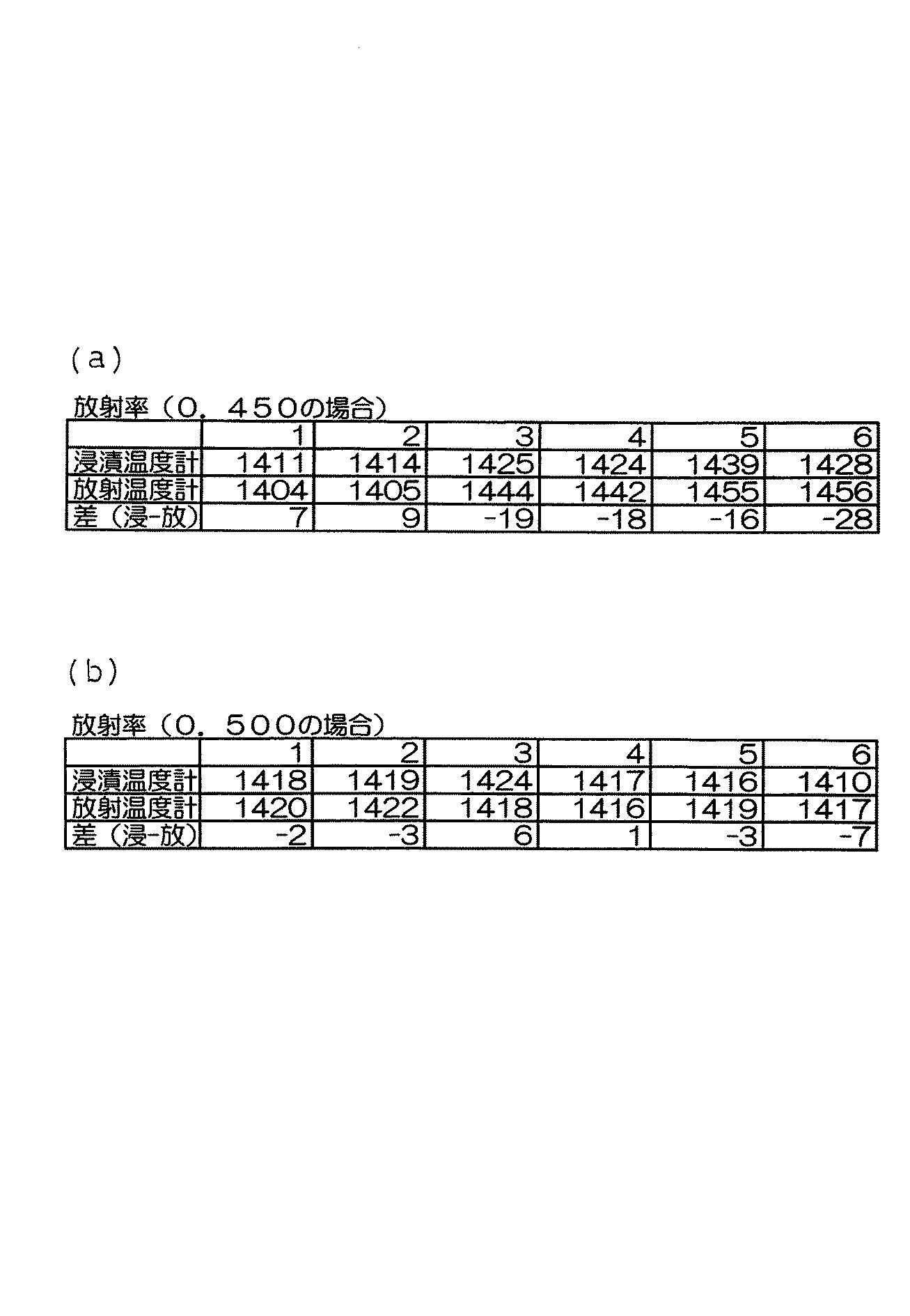
図4(a),(b)に示すように、本発明の放射温度計7を用いたシステムと従来の浸漬温度計との温度比較を行ったところ、図4(a)のようにアンプの放射率設定を0.450とした場合、最大28°Cの温度差があった。そこで、放射率の設定を徐々に変化させ、図4(b)のように0.500設定で比較したところ、最大でも7°Cという結果を得ることができた。尚、浸漬温度計は、ストッパーロッド(出湯口)周辺で温度測定実施した。
As shown in FIGS. 4 (a) and 4 (b), a temperature comparison between a system using the
上記実施例の方法によれば、溶湯の温度の正確な測定及び推定ができるとともに、この推定した溶湯温度に基づいて、鋳型一枠内の溶湯温度を容易に最適な目標温度帯に管理できるので、湯回り不良等の温度低下に起因した鋳造欠陥を防止してより良質な継手を製造するという利点がある。 According to the method of the above embodiment, it is possible to accurately measure and estimate the temperature of the molten metal, and based on the estimated molten metal temperature, it is possible to easily manage the molten metal temperature in one mold frame to an optimum target temperature range. There is an advantage of producing a better quality joint by preventing casting defects caused by a temperature drop such as poor hot water.
本発明は上記実施例に何等限定されるものではなく、この要旨を逸脱しない範囲内に於いて種々なる態様で実施し得ることは勿論である。本発明では、特に、タンディッシュの底部から溶湯が落下するレーザー検知式の自動注湯機に適用されると好適であるが、それ以外にも、取鍋傾動式自動注湯機にも適用できる。 The present invention is not limited to the above-described embodiment, and it is needless to say that the present invention can be implemented in various modes without departing from the gist of the present invention. In the present invention, it is particularly suitable to be applied to a laser detection type automatic pouring machine in which the molten metal falls from the bottom of the tundish, but in addition, it can also be applied to a ladle tilting type automatic pouring machine. .
1 自動注湯機
3 溶湯
4 タンディッシュ
5 鋳型
7 放射温度計
1 Automatic pouring machine
3
5
Claims (5)
Priority Applications (1)
| Application Number | Priority Date | Filing Date | Title |
|---|---|---|---|
| JP2008049234A JP2009204556A (en) | 2008-02-29 | 2008-02-29 | Molten metal temperature measuring method |
Applications Claiming Priority (1)
| Application Number | Priority Date | Filing Date | Title |
|---|---|---|---|
| JP2008049234A JP2009204556A (en) | 2008-02-29 | 2008-02-29 | Molten metal temperature measuring method |
Publications (1)
| Publication Number | Publication Date |
|---|---|
| JP2009204556A true JP2009204556A (en) | 2009-09-10 |
Family
ID=41146968
Family Applications (1)
| Application Number | Title | Priority Date | Filing Date |
|---|---|---|---|
| JP2008049234A Pending JP2009204556A (en) | 2008-02-29 | 2008-02-29 | Molten metal temperature measuring method |
Country Status (1)
| Country | Link |
|---|---|
| JP (1) | JP2009204556A (en) |
Cited By (7)
| Publication number | Priority date | Publication date | Assignee | Title |
|---|---|---|---|---|
| WO2014024955A1 (en) * | 2012-08-10 | 2014-02-13 | ヤンマー株式会社 | Casting quality management system and method |
| JP2014034058A (en) * | 2012-08-10 | 2014-02-24 | Yanmar Co Ltd | System and method for control of casting quality |
| JP2014035338A (en) * | 2012-08-10 | 2014-02-24 | Yanmar Co Ltd | Molten metal temperature measuring system and method |
| CN108188385A (en) * | 2018-01-19 | 2018-06-22 | 青岛贝诺磁电科技有限公司 | A kind of casting smelting real time data synchronization manages system |
| CN113020553A (en) * | 2019-12-24 | 2021-06-25 | 新东工业株式会社 | Pouring device |
| JP2023032848A (en) * | 2021-08-27 | 2023-03-09 | 新東工業株式会社 | Casting facility |
| US20240003758A1 (en) * | 2020-12-02 | 2024-01-04 | Heraeus Electro-Nite International N.V. | Method and system for determining a series of temperature values of a molten metal bath |
-
2008
- 2008-02-29 JP JP2008049234A patent/JP2009204556A/en active Pending
Cited By (9)
| Publication number | Priority date | Publication date | Assignee | Title |
|---|---|---|---|---|
| WO2014024955A1 (en) * | 2012-08-10 | 2014-02-13 | ヤンマー株式会社 | Casting quality management system and method |
| JP2014034058A (en) * | 2012-08-10 | 2014-02-24 | Yanmar Co Ltd | System and method for control of casting quality |
| JP2014035338A (en) * | 2012-08-10 | 2014-02-24 | Yanmar Co Ltd | Molten metal temperature measuring system and method |
| CN108188385A (en) * | 2018-01-19 | 2018-06-22 | 青岛贝诺磁电科技有限公司 | A kind of casting smelting real time data synchronization manages system |
| CN113020553A (en) * | 2019-12-24 | 2021-06-25 | 新东工业株式会社 | Pouring device |
| JP2021102213A (en) * | 2019-12-24 | 2021-07-15 | 新東工業株式会社 | Molten metal pouring device |
| JP7281395B2 (en) | 2019-12-24 | 2023-05-25 | 新東工業株式会社 | Pouring device |
| US20240003758A1 (en) * | 2020-12-02 | 2024-01-04 | Heraeus Electro-Nite International N.V. | Method and system for determining a series of temperature values of a molten metal bath |
| JP2023032848A (en) * | 2021-08-27 | 2023-03-09 | 新東工業株式会社 | Casting facility |
Similar Documents
| Publication | Publication Date | Title |
|---|---|---|
| JP2009204556A (en) | Molten metal temperature measuring method | |
| JP5039782B2 (en) | Continuous casting apparatus and method using molten mold flux | |
| JP4700730B2 (en) | Apparatus for continuous temperature measurement of molten steel in tundish using optical fiber and infrared pyrometer | |
| US9546909B2 (en) | Apparatus and methods for continuous temperature measurement of molten metals | |
| WO2010064727A1 (en) | Method of determining temperature of molten pig iron and method of operating blast furnace using same | |
| US9427796B2 (en) | Method for continuously casting ingot made of titanium or titanium alloy | |
| JP2018536085A (en) | Laser sensor for melt control in furnace-type blast furnaces | |
| JPH01267426A (en) | Temperature measuring device for molten metal | |
| CN115041642B (en) | Tapping method of converter | |
| JP6050173B2 (en) | Plasma heating control apparatus and plasma heating control method | |
| JP6079670B2 (en) | Breakout prediction method in continuous casting equipment. | |
| JP4273860B2 (en) | Continuous casting method of magnesium alloy melt | |
| KR101998726B1 (en) | Apparatus for processing molten metal | |
| CN211373207U (en) | Real-time monitoring device for molten aluminum of heat preservation furnace | |
| JPH0238932A (en) | Continuous temperature measuring method for molten metal | |
| KR102511007B1 (en) | Apparatus for measuring molten iron temperature of blast furnace | |
| KR20120015981A (en) | Silicon ingot electronic casting device | |
| JP2013076133A (en) | Continuous casting method | |
| JPH0557426A (en) | Ladle for casting | |
| JPH054928Y2 (en) | ||
| JP2002146426A (en) | Molten steel radiation temperature measurement method | |
| JPS6293051A (en) | Molten steel injection method in continuous casting | |
| RU2009141866A (en) | METHOD OF CONTROL OF PURITY OF METAL MELTS | |
| JPH0560774A (en) | Apparatus for measuring flow velocity of fused steel | |
| JPH03124351A (en) | Device for controlling plasma heating to molten steel in tundish in continuous casting equipment |