JP2009189818A - Golf club head and manufacturing method thereof - Google Patents
Golf club head and manufacturing method thereof Download PDFInfo
- Publication number
- JP2009189818A JP2009189818A JP2009030518A JP2009030518A JP2009189818A JP 2009189818 A JP2009189818 A JP 2009189818A JP 2009030518 A JP2009030518 A JP 2009030518A JP 2009030518 A JP2009030518 A JP 2009030518A JP 2009189818 A JP2009189818 A JP 2009189818A
- Authority
- JP
- Japan
- Prior art keywords
- golf club
- groove
- section
- cross
- club face
- Prior art date
- Legal status (The legal status is an assumption and is not a legal conclusion. Google has not performed a legal analysis and makes no representation as to the accuracy of the status listed.)
- Granted
Links
Images


Classifications
-
- A—HUMAN NECESSITIES
- A63—SPORTS; GAMES; AMUSEMENTS
- A63B—APPARATUS FOR PHYSICAL TRAINING, GYMNASTICS, SWIMMING, CLIMBING, OR FENCING; BALL GAMES; TRAINING EQUIPMENT
- A63B53/00—Golf clubs
- A63B53/04—Heads
- A63B53/047—Heads iron-type
-
- A—HUMAN NECESSITIES
- A63—SPORTS; GAMES; AMUSEMENTS
- A63B—APPARATUS FOR PHYSICAL TRAINING, GYMNASTICS, SWIMMING, CLIMBING, OR FENCING; BALL GAMES; TRAINING EQUIPMENT
- A63B53/00—Golf clubs
- A63B53/04—Heads
- A63B53/0445—Details of grooves or the like on the impact surface
-
- B—PERFORMING OPERATIONS; TRANSPORTING
- B23—MACHINE TOOLS; METAL-WORKING NOT OTHERWISE PROVIDED FOR
- B23C—MILLING
- B23C3/00—Milling particular work; Special milling operations; Machines therefor
- B23C3/28—Grooving workpieces
- B23C3/30—Milling straight grooves, e.g. keyways
-
- B—PERFORMING OPERATIONS; TRANSPORTING
- B23—MACHINE TOOLS; METAL-WORKING NOT OTHERWISE PROVIDED FOR
- B23C—MILLING
- B23C5/00—Milling-cutters
- B23C5/02—Milling-cutters characterised by the shape of the cutter
- B23C5/10—Shank-type cutters, i.e. with an integral shaft
-
- B—PERFORMING OPERATIONS; TRANSPORTING
- B23—MACHINE TOOLS; METAL-WORKING NOT OTHERWISE PROVIDED FOR
- B23P—METAL-WORKING NOT OTHERWISE PROVIDED FOR; COMBINED OPERATIONS; UNIVERSAL MACHINE TOOLS
- B23P13/00—Making metal objects by operations essentially involving machining but not covered by a single other subclass
- B23P13/02—Making metal objects by operations essentially involving machining but not covered by a single other subclass in which only the machining operations are important
-
- Y—GENERAL TAGGING OF NEW TECHNOLOGICAL DEVELOPMENTS; GENERAL TAGGING OF CROSS-SECTIONAL TECHNOLOGIES SPANNING OVER SEVERAL SECTIONS OF THE IPC; TECHNICAL SUBJECTS COVERED BY FORMER USPC CROSS-REFERENCE ART COLLECTIONS [XRACs] AND DIGESTS
- Y10—TECHNICAL SUBJECTS COVERED BY FORMER USPC
- Y10T—TECHNICAL SUBJECTS COVERED BY FORMER US CLASSIFICATION
- Y10T29/00—Metal working
- Y10T29/49—Method of mechanical manufacture
- Y10T29/49995—Shaping one-piece blank by removing material
-
- Y—GENERAL TAGGING OF NEW TECHNOLOGICAL DEVELOPMENTS; GENERAL TAGGING OF CROSS-SECTIONAL TECHNOLOGIES SPANNING OVER SEVERAL SECTIONS OF THE IPC; TECHNICAL SUBJECTS COVERED BY FORMER USPC CROSS-REFERENCE ART COLLECTIONS [XRACs] AND DIGESTS
- Y10—TECHNICAL SUBJECTS COVERED BY FORMER USPC
- Y10T—TECHNICAL SUBJECTS COVERED BY FORMER US CLASSIFICATION
- Y10T409/00—Gear cutting, milling, or planing
- Y10T409/30—Milling
- Y10T409/306664—Milling including means to infeed rotary cutter toward work
- Y10T409/307784—Plural cutters
-
- Y—GENERAL TAGGING OF NEW TECHNOLOGICAL DEVELOPMENTS; GENERAL TAGGING OF CROSS-SECTIONAL TECHNOLOGIES SPANNING OVER SEVERAL SECTIONS OF THE IPC; TECHNICAL SUBJECTS COVERED BY FORMER USPC CROSS-REFERENCE ART COLLECTIONS [XRACs] AND DIGESTS
- Y10—TECHNICAL SUBJECTS COVERED BY FORMER USPC
- Y10T—TECHNICAL SUBJECTS COVERED BY FORMER US CLASSIFICATION
- Y10T82/00—Turning
- Y10T82/10—Process of turning
Landscapes
- Engineering & Computer Science (AREA)
- Mechanical Engineering (AREA)
- Health & Medical Sciences (AREA)
- General Health & Medical Sciences (AREA)
- Physical Education & Sports Medicine (AREA)
- Golf Clubs (AREA)
Abstract
Description
本出願は、2008年2月15日に出願された米国仮特許出願番号61/029,205、及び2008年8月11日に出願された米国特許出願番号12/189,606に基づく優先権を主張する。 This application is based on US Provisional Patent Application No. 61 / 029,205 filed on February 15, 2008, and US Patent Application No. 12 / 189,606 filed on August 11, 2008. Insist.
本願に開示される技術は広くゴルフクラブに関し、特にその表面に溝を有するゴルフクラブヘッドに関する。 The technology disclosed in this application relates generally to golf clubs, and more particularly to a golf club head having a groove on the surface thereof.
ゴルフクラブの製造業者は、ゴルフクラブフェースに溝を有するゴルフクラブヘッドを製造する。製造業者は、溝付け機(グルーブカッター)を回転させることにより、ゴルフクラブフェースに溝を付ける。従来、ゴルフクラブフェースの溝は、ゴルフクラブフェースに対して平行に配置された溝付け機によって形成されていた(即ち、工具の回転軸がストライクフェースに対して平行に配置されていた)。 Golf club manufacturers produce golf club heads having grooves in the golf club face. The manufacturer grooves the golf club face by rotating a grooving machine (groove cutter). Conventionally, the groove of the golf club face has been formed by a grooving machine arranged parallel to the golf club face (that is, the rotation axis of the tool was arranged parallel to the strike face).
上記の例では、溝形成工具(例えば、溝付け機)は、一様でない磨耗、及び/又は過剰な振動を起こしてしまうことがある。この結果、形成するゴルフクラブフェースの溝が変形してしまい、仕様に沿った期待通りの正確な形でなくなってしまうおそれがある。 In the above example, the grooving tool (eg, grooving machine) may cause uneven wear and / or excessive vibration. As a result, the groove of the golf club face to be formed may be deformed and may not have the exact shape as expected according to the specifications.
本願に開示される技術は、ゴルフクラブヘッドを製造する方法に具現化することができる。この方法は、ゴルフクラブフェースを有するゴルフクラブヘッドを用意する工程と、ゴルフクラブフェースに溝を形成する工程を有する。溝を形成する工程は、溝形成工具をゴルフクラブフェースに対して実質的に0°よりも大きく、実質的に90°よりも小さい角度の回転軸で回転させ、該角度において溝形成工具をゴルフクラブフェースの第1端から第2端まで移動させる。この方法は、ゴルフクラブフェースに複数の平行溝を形成する工程と、シャフトをゴルフクラブヘッドに結合させてゴルフクラブを形成する工程をさらに備えていてもよい。 The technology disclosed in the present application can be embodied in a method of manufacturing a golf club head. This method includes the steps of providing a golf club head having a golf club face and forming a groove in the golf club face. The step of forming the groove comprises rotating the groove forming tool with respect to the golf club face with a rotation axis having an angle substantially greater than 0 ° and substantially less than 90 °, at which the groove forming tool is golfed. The club face is moved from the first end to the second end. The method may further include the steps of forming a plurality of parallel grooves in the golf club face and forming a golf club by coupling the shaft to the golf club head.
さらに、本願に開示される技術は、複数の溝を有するゴルフクラブフェースを備えたゴルフクラブヘッドに具現化することができる。このゴルフクラブヘッドでは、複数の溝の1つにおける第1端の第1領域における第1断面が、第1端の第1領域の側壁の縁(エッジ)に対して垂直である。また、前述の第1端の第2領域における第2断面が第1端の第2領域の側壁の縁(エッジ)に対して垂直である。また、第1断面は第2断面に対して実質的に相似であり、第1断面と第2断面はそれぞれ対称である。さらに、前述の第1端の第1領域における第3断面は、第1端の第1領域の底に対して垂直である。そして、前述の第1端の第2領域における第4断面は、第1端の第2領域の底に対して垂直である。第3断面は第4断面に対して実質的に非相似であり、第3断面と第4断面はそれぞれ対称である。 Furthermore, the technology disclosed in the present application can be embodied in a golf club head including a golf club face having a plurality of grooves. In this golf club head, the first cross section in the first region of the first end in one of the plurality of grooves is perpendicular to the edge (edge) of the side wall of the first region of the first end. Further, the second cross section in the second region at the first end is perpendicular to the edge (edge) of the side wall of the second region at the first end. The first cross section is substantially similar to the second cross section, and the first cross section and the second cross section are symmetrical. Furthermore, the third cross section in the first region at the first end is perpendicular to the bottom of the first region at the first end. The fourth cross section in the second region at the first end is perpendicular to the bottom of the second region at the first end. The third cross section is substantially dissimilar to the fourth cross section, and the third cross section and the fourth cross section are symmetric.
簡素で明瞭な説明のために、図面では構造を概要的に表わしている。周知の特徴及び技術に係る詳細及び説明は、ゴルフクラブとその製造方法をいたずらに不明瞭にすることを避けるために省略することがある。さらに、図面中の要素は、必ずしも正確な縮小率で描かれていない。例えば、図面中のいくつかの要素の寸法は、ゴルフクラブヘッド及び製造方法の様々な実施形態の理解を助けるために、他の要素と比較して誇張して描かれていることがある。異なる図面における同一の符号は、同一の要素であることを意味する。 For the sake of simplicity and clarity, the structure is schematically depicted in the drawings. Details and descriptions of well-known features and techniques may be omitted to avoid unnecessarily obscuring the golf club and its manufacturing method. Further, elements in the drawings are not necessarily drawn with an accurate reduction ratio. For example, the dimensions of some elements in the drawings may be exaggerated compared to other elements to aid in understanding various embodiments of golf club heads and manufacturing methods. The same reference numerals in different drawings mean the same elements.
説明及び請求項の「第1」、「第2」、「第3」、「第4」等の用語は、たとえ用いられていたとしても、類似の要素を区別するために用いられており、必ずしも特定の順序及び時間的な順序を表わすものではない。ここに記載されるゴルフクラブ及び製造方法に係る実施形態がここに図示又は記載される事項以外の順序で実施可能であるように、そのような用語はしかるべき状況に応じて置換可能であると理解すべきである。また、「包含する」、「含む」、「有する」という用語及びそれらの他の変形例は、その他の含有物を非限定的に含むことを意図している。即ち、列挙された要素を備えたプロセス、方法、物又は装置は、それらの要素に必ずしも限定されるのではなく、そのようなプロセス、方法、物又は装置に明白に列挙されていない他の要素又は固有のものではない他の要素を含んでいてもよい。 The terms “first”, “second”, “third”, “fourth”, etc. in the description and claims are used to distinguish similar elements, even if used, It does not necessarily represent a specific order and time order. It is understood that such terms are interchangeable depending on the appropriate circumstances so that embodiments of the golf club and method of manufacture described herein may be performed in an order other than that illustrated or described herein. Should be understood. Also, the terms “including”, “including”, “having” and other variations thereof are intended to include, but are not limited to, other ingredients. That is, a process, method, article or device with the listed elements is not necessarily limited to those elements, but other elements not explicitly listed in such processes, methods, articles or devices. Alternatively, other elements that are not unique may be included.
説明及び請求項の「左」、「右」、「フロント(前)」、「バック(後)」、「トップ(上)」、「ボトム(底)」、「サイド(横)」、「下の」等の用語は、たとえ用いられていたとしても、説明的な目的のために用いられており、普遍的な位置関係を説明するものではない。ここに記載されるゴルフクラブ及び製造方法に係る実施形態がここに図示又は記載される事項以外の位置関係で実施可能であるように、そのような用語はしかるべき状況に応じて置換可能であると理解すべきである。ここで用いられる「結合した」という用語は、電気的、物理的、機械的又は他の方法で直接的又は間接的に接続していることが定義されている。 “Left”, “Right”, “Front (front)”, “Back (back)”, “Top (top)”, “Bottom (bottom)”, “Side (side)”, “Bottom” Terms such as "" are used for explanatory purposes, even if used, and do not describe universal positional relationships. Such terms are interchangeable as appropriate, so that embodiments of the golf clubs and manufacturing methods described herein can be implemented in a positional relationship other than those shown or described herein. Should be understood. The term “coupled” as used herein is defined as being connected directly or indirectly in electrical, physical, mechanical or other ways.
1つの例では、ゴルフクラブは、ゴルフクラブフェースとそのゴルフクラブフェースに設けられた複数の溝を有するゴルフクラブヘッドを備え得る。複数の溝のそれぞれは、ゴルフクラブフェースの第1端から第2端まで伸びている。第1端と第2端はそれぞれ、楕円部分を備えている。第1断面が溝の第1領域の側壁に対して垂直であり、かつ、第2断面も溝の第2領域の側壁に対して垂直であると、溝の第1領域における第1断面は溝の第2領域における第2断面に対して実質的に相似である。第3断面が溝の第1領域の底に対して垂直であり、かつ、第4断面も溝の第2領域の底に対して垂直であると、溝の第1領域における第3断面は溝の第2領域における第2断面に対して実質的に非相似である。この例では、第1断面、第2断面、第3断面及び第4断面はそれぞれ対称である。 In one example, a golf club may include a golf club head having a golf club face and a plurality of grooves provided in the golf club face. Each of the plurality of grooves extends from the first end to the second end of the golf club face. Each of the first end and the second end includes an elliptical portion. When the first cross section is perpendicular to the side wall of the first region of the groove and the second cross section is also perpendicular to the side wall of the second region of the groove, the first cross section in the first region of the groove is the groove. Is substantially similar to the second cross section in the second region. If the third cross section is perpendicular to the bottom of the first region of the groove and the fourth cross section is also perpendicular to the bottom of the second region of the groove, the third cross section in the first region of the groove is the groove. And substantially non-similar to the second cross section in the second region. In this example, the first cross section, the second cross section, the third cross section, and the fourth cross section are symmetrical.
ここで開示される様々な例では、溝形成工具は、約0.60センチから約3.1センチの間の直径を備え得る。溝形成工具は、ゴルフクラブフェースの高さ以下の長さを備え得る。溝形成工具の回転軸の方向は、ゴルフクラブフェースから約30°と約60°の間の角度を有している。一例では、溝形成工具の回転軸の角度は約45°である。一例の溝形成工具の回転軸の角度は、約30°よりも小さい及び/又は約60°よりも大きくすることができる。しかしながら、そのような一例の角度は実質的に0°よりも大きく、実質的に90°よりも小さい。他の例では、溝形成工具の回転軸の方向は、2°と43°の間の角度であり、一例では、約35°である。 In various examples disclosed herein, the grooving tool may comprise a diameter between about 0.60 centimeters and about 3.1 centimeters. The groove forming tool may have a length that is less than or equal to the height of the golf club face. The direction of the axis of rotation of the grooving tool has an angle between about 30 ° and about 60 ° from the golf club face. In one example, the angle of the rotational axis of the grooving tool is about 45 °. The angle of the axis of rotation of an example grooving tool can be less than about 30 ° and / or greater than about 60 °. However, such an example angle is substantially greater than 0 ° and substantially less than 90 °. In another example, the direction of the axis of rotation of the grooving tool is an angle between 2 ° and 43 °, and in one example about 35 °.
ここで開示される様々な例では、溝形成工具の回転させる工程は、ゴルフクラブフェースに対する接触先端の速度が略一定となる状態で、溝形成工具を回転させることを備えている。溝形成工具速度は、約45表面メートル/分(smm)から約800表面メートル/分(smm)の間とすることができる。溝形成工具速度は、約90表面メートル/分から約300表面メートル/分の間としてもよい。 In the various examples disclosed herein, the step of rotating the groove forming tool includes rotating the groove forming tool in a state where the speed of the contact tip with respect to the golf club face is substantially constant. The grooving tool speed can be between about 45 surface meters / minute (smm) to about 800 surface meters / minute (smm). The grooving tool speed may be between about 90 surface meters / minute and about 300 surface meters / minute.
ゴルフクラブフェースに1つ以上の溝を提供する溝形成工具に角度を持たせることにより、溝はそれぞれの端部に楕円部を有することができる。多くの例では、その楕円部は、ゴルフクラブフェースのインパクト領域の外に配置され得る。様々な例は、ゴルフクラブフェースのトウ領域に対応し得る第1端、及びゴルフクラブフェースのヒール領域に対応し得る第2端に対応した溝端を備えることができる。さらに、トウ領域又はヒール領域のいずれかの溝端は、ゴルフクラブフェースのレール領域に向かって上向きに先細ってもよいし、又はゴルフクラブフェースのソール領域に向かって下向きに先細ってもよい。 By angling a groove-forming tool that provides one or more grooves in a golf club face, the grooves can have an ellipse at each end. In many instances, the ellipse may be located outside the impact area of the golf club face. Various examples can include a groove end corresponding to a first end that can correspond to a toe region of the golf club face and a second end that can correspond to a heel region of the golf club face. Furthermore, the groove end of either the toe region or the heel region may taper upward toward the rail region of the golf club face or taper downward toward the sole region of the golf club face.
様々な例によると、溝形成工具は、溝を形成するために、ゴルフクラブフェースの第1端から第2端までシングルパス(単一パス)によって作動され得る。シングルパスの作動は、実質的に直線状の側壁を有する溝を形成することができる。さらに、異なる溝形成工具は、溝を形成するために、ゴルフクラブフェースの第1端から第2端まで少なくともツーパスによって作動され得る。複数パスの作動は、実質的に曲線状の側壁を有する溝を形成することができる。ここで開示される例では、USGA及びR&Aのような様々なゴルフ標準組織、統治体、及び/又はルール制定事業体によって定義されたゴルフのルール及び/又は標準に則した溝を形成することができる点に留意されたい。しかしながら、全ての実施形態がそのような規定に拘束されるものに限定されるとは限らない。 According to various examples, the grooving tool can be actuated by a single pass from the first end to the second end of the golf club face to form a groove. Single pass actuation can form grooves with substantially straight sidewalls. Further, the different grooving tools can be actuated at least two passes from the first end to the second end of the golf club face to form a groove. Multiple pass actuation can form grooves with substantially curved sidewalls. In the examples disclosed herein, forming grooves according to golf rules and / or standards defined by various golf standards organizations, governing bodies, and / or rule-making entities such as USGA and R & A, etc. Note that you can. However, not all embodiments are limited to those restricted by such rules.
ここで図面に戻る。図1は、第1の実施形態に基づいており、ゴルフクラブの溝の一例が提供される1つの方法を示すフロー図である。ゴルフクラブヘッド及び製造方法の一例では、ゴルフクラブヘッドを製造する方法100は、ゴルフクラブフェースを有するゴルフクラブヘッドを用意する工程(ステップ110)と、ゴルフクラブフェースに溝を形成する工程(ステップ120)を備えることができる。ゴルフクラブフェースに溝を形成する工程は、ゴルフクラブフェースに対して実質的に0°よりも大きく実質的に90°よりも小さい角度の回転軸で溝形成工具を回転させること(ステップ122)、その角度でゴルフクラブフェースの第1端から第2端まで溝形成工程を作動させること(ステップ124)を備えることができる。この結果、ゴルフクラブフェースに溝が形成され得る。方法はさらに、ゴルフクラブヘッドにシャフトを結合させることによってゴルフクラブを形成する工程を備えることができる(ステップ130)。図1の方法には、特定の動作順序が概説されているが、これらの動作は他の順序で実施することも可能である。例えば、図1に示される2つ以上の動作は、連続して実施してもよいし、並列に、あるいは同時に実施してもよい。
Returning now to the drawing. FIG. 1 is a flow diagram illustrating one method based on the first embodiment in which an example golf club groove is provided. In one example of a golf club head and manufacturing method, the
様々な実施例においては、図2に示されるように、ゴルフクラブフェース220に溝240を提供するためにゴルフクラブヘッド210に接触することが可能な溝形成工具230によって、本発明の方法が具現化される。ゴルフクラブ200は、ゴルフクラブフェース220とそのゴルフクラブフェース220に複数の溝を有するゴルフクラブヘッド210を備えている。各溝240は、ゴルフクラブフェース220の第1端214(例えば、トウ端側)から第2端212(例えば、ヒール端側)に伸びている。第1端214と第2端212のそれぞれは楕円部を備えることができ、例えば楕円部501(図5)である。ゴルフクラブ200はさらに、インパクト領域295とゴルフクラブシャフト298を備えることができる。ゴルフクラブシャフト298がゴルフクラブヘッド210のホーゼル299に結合すると、ゴルフクラブシャフト298はゴルフクラブ200の一例を形成することができる。ゴルフクラブシャフト298は、溝240を形成するときには、ゴルフクラブヘッド210から取り外しておいてもよい。
In various embodiments, as shown in FIG. 2, the method of the present invention is embodied by a
図2は、溝形成装置231に接触するゴルフクラブヘッド210の正面図を示す。図2に示されるように、溝形成工具230は、溝形成装置231の一部であり得る。溝形成装置231は、溝形成工具230を固定するとともに、溝240を形成するために溝形成工具230を作動させることができる。溝形成工具230は、溝形成装置231から取り外すことが可能であり、様々なサイズ又は交換用の溝形成工具230を用いることができる。例えば、異なる溝形成工具は、異なる直径、長さ及び/又は材質を備えることができる。
FIG. 2 shows a front view of the
一例では、溝形成装置231は、作動中の溝形成工具230が溝240を形成するために、ゴルフクラブフェース220を横切って矢印275で示されるいずれかの方向に移動する。他の例では、溝形成装置231が固定されており、ゴルフクラブヘッド210が矢印275のいずれかの方向に移動し、溝240を形成することができる。また、さらに例では、溝形成装置231とゴルフクラブヘッド210のいずれもが同時に逆方向に移動して、溝240を形成することができる。
In one example, the
一例では、図2に示されるように、ゴルフクラブフェース220は複数の溝240を備えている。また、一実施形態においては、それらの複数の溝240はお互いに平行である。溝形成装置231の一部である溝形成工具230は、溝240を1つ1つ形成することができる。最初の1つの溝240が形成されると、溝形成装置231は再配置され、前記1つの溝240に平行な第2の溝240を溝形成工具230によって形成することができる。そのプロセスは各溝240が形成されるまで続けられ得る。後述でより詳細に記載するが、溝形成工具230及び溝形成装置231によって形成される溝240のそれぞれを、シングルパス(単一パス)によって形成することもでき、又はマルチプルパス(複数パス)によって形成することもできる。この製造技術によると、シングルパスで溝が形成されると、製造精度が高くありながら処理能力(スループット)が向上する。また、マルチプルパスで溝が形成されると、同じ幅でありながら異なる断面積を有する溝が得られる(ここでいう幅は、ゴルフクラブフェース220の表面における側壁の縁の間の幅である)。
In one example, as shown in FIG. 2, the
様々な例では、ゴルフクラブヘッド210はインパクト領域295を備えている。インパクト領域295は、使用者がゴルフクラブヘッド200を使用したときに、ボールを打つ領域である。インパクト領域295は、ゴルフクラブに基づいて様々なサイズ、形状及び直径を有することができる。一般的に、溝240はインパクト領域295の周囲を越えて伸びることができる。インパクト領域295内の溝240は、使用者がゴルフクラブ200を使用する様々な状況下で、ゴルフボール(図示せず)に「バイト」及び/又は「スピン」を与える。このような様々な状況下でゴルフボールに異なる「バイト」及び/又は「スピン」を与えるために、様々な溝形成工具は、異なる溝の深さ、幅又は他の溝の特徴を有する様々な溝を形成するために用いられる。
In various examples, the
様々な例において、図3は、図2の正面図と同様にゴルフクラブヘッド210に接触する溝形成工具230の側面図を示す。溝形成工具230は、概ねゴルフクラブフェース220の高さ321以下の長さ332を有することができる。溝形成工具230の長さを最適化することによって、長さ332によっては、溝のフライス加工、研削、研磨又はカッティング工程中に溝形成装置231とゴルフクラブヘッド210がお互いに干渉しないようにして方法100を実行することができる。換言すると、溝形成工具230が短すぎると、特定の角度において、溝形成工具230がゴルフクラブフェース220の下側に溝241を形成するときに、溝形成装置231がゴルフクラブフェース220の上側に干渉する。さらに、長さ332は、溝形成工具230の回転によって過剰な振動を生じさせないとともに、溝形成工具230からの力によって過度のモーメントがゴルフクラブフェース220に与えられない長さ(短さ)にすべきである。長さ332を短くすることにより許容できない寸法誤差を有する溝240の形成が抑制される。
In various examples, FIG. 3 shows a side view of the
溝形成工具230の方向は、ゴルフクラブフェース220に対して約30°から約60°の間の角度360を有する回転軸352を備えている。一例では、角度360は、約45°である。溝形成工具の回転軸352の一例の方向は、約30°よりも小さく、及び/又は約60°よりも大きな角度360を有することもでき、且つ、角度360は実質的に0°よりも大きく実質的に90°よりも小さい。例えば、角度360は、約5°又は約85°とすることができる。他の例では、角度360は約2°と約43°の間であり、例えば35°である。溝形成工具の長さは、適切な角度を選択することによって、よりコンパクトにすることができる。ここで開示される方法、装置及び製造物は、この場合に限定されるものではない。溝形成工具230は、時計回りの回転方向350を備えている。なお、回転方向350は反時計回りでもよい。
上記技術によると、溝形成工具230は、上記範囲内の特定の角度の回転軸352回りに回転され、それにより、従来技術と比較して、溝形成工具230の長さをより短くすることが可能になる。そのため、溝形成工具230は、ゴルフクラブフェース220に溝を形成するときの剛性及び安定性を向上させることができる。この構成によると、振動及び工具の磨耗は顕著に減少され得る。
さらに、上記の角度をつけることによって、形成する溝の幅を柔軟に変えることができる。例えば、切り込みの深さを制御することによって、溝の幅を容易に調整することができる(例えば、深い切り込みは広い幅の溝を形成し、浅い切り込みは狭い幅の溝を形成する)。また、単純に工具の角度を変えるだけで、溝の内壁の傾斜をも容易に調整することができる。上記技術によると、正確で所望の仕様のゴルフクラブヘッド及びゴルフクラブが得られる。
The direction of the
According to the above technique, the
Furthermore, the width of the groove to be formed can be flexibly changed by providing the above angle. For example, by controlling the depth of the cut, the width of the groove can be easily adjusted (for example, a deep cut forms a wide groove and a shallow cut forms a narrow width groove). Further, the inclination of the inner wall of the groove can be easily adjusted by simply changing the angle of the tool. According to the above technique, a golf club head and a golf club having accurate and desired specifications can be obtained.
ここに開示される様々な例では、溝形成工具230は、異なる材質、例えば、溝240のような例の溝を形成するときに抗磨耗を提供し得る高速度鋼、炭化タングステン、炭化チタン、及び他の材料を備えることができる。製造業者の要求に基づいて、せん断又は圧縮特性に有益な他のあらゆる材料も本願の意図するところである。
In various examples disclosed herein, the
上記で述べられるように、ゴルフクラブフェース220は、平行な複数の溝240を備えることができる(図2)。一例では、溝240は、ゴルフクラブフェース220を横切って溝形成工具230を作動させ、次に、溝形成工具230を有する溝形成装置231をゴルフクラブフェース220の次の位置に再配置させることによって形成される。溝のフライス加工、研削、研磨又は切り込み工程は、複数の溝240が形成されるまで繰返される。方向275(図2)における溝形成装置231とゴルフクラブヘッド210の動作と同様に、溝形成装置231とゴルフクラブヘッド210は互いに水平370に移動することができ、これにより溝形成工具230をゴルフクラブフェース220上でさらに再配置することができる。
As mentioned above, the
次の図4は、ゴルフクラブヘッド210の一部の断面図に接触する溝形成工具430の拡大図を示しており、溝241の対称な断面図が含まれる。溝形成工具430を回転させる工程は、ゴルフクラブヘッド220との接触先端480において略一定の速度で溝形成工具430を回転させる工程を備えることができる。そのように溝形成工具430を動作させると、寿命が長くなり得る。さらに、一定速度での動作によると、ゴルフクラブフェースに対して一定の圧力を印加することができる。このため、工具及びゴルフクラブフェースの振動を低減させることができる。溝形成工具の精度が向上し得る。溝形成工具の速度は、約45表面メートル/分から約800表面メートル/分の範囲であってもよい。一例では、溝形成工具の速度は、約90表面メートル/分から約300表面メートル/分の間で設定することができる。速度の幅は、最小速度が溝の切り込みを実行するのに要する熱を提供でき、最大速度が溝形成工具又は形成された溝が溶融するほど過剰な熱を提供しない範囲で決定される。即ち、速度は、溝形成工程中に生成される熱量を最適化するために利用され得る。ここでは速度の一例が開示されているが、本発明に含まれる全ての速度の例がこれに限定されるものではない。図4に示されるように、ここで開示される速度は、切り込み、フライス加工、研削又は研磨に用いられる溝形成工具430の最外周の先端部分(例えば、先端480)の速度に対応している。ここで開示される様々な例では、溝形成工具は、約0.60から約3.1センチメートルの範囲内の直径481を有する。上述されるように、溝形成工具430の直径481は、製造業者の要求に応じて様々な直径であり得る。さらに、溝形成工具の直径は、ホーゼルとそのホーゼルに近接する溝端との間の距離に応じて決定される。そのように、最小の長さ(ここで利用され得る溝形成工具では最大の剛性及び安定性を有する)を有する溝形成工具は、ゴルフクラブヘッドの形状に応じて、必要に応じて利用され得る。
4 shows an enlarged view of the
溝形成工具430は他の形態を有することができる。例えば、溝形成工具430は、溝形成工具の切り込み、フライス加工、研削又は研磨用の最外周の先端部分が溝形成工具の本体(即ち、図2及び図3に示されるように、それ自身のシャフト部)よりも大きな直径を有し、図2及び図3の溝形成工具230によって示される形態を有することができる。
The
溝端の一例の拡大断面図を示す図5及び図6を参照すると、例えば、楕円部501(図5)及び楕円部602(図6)のように、溝は各溝端において楕円部を有することができる。上述したように、一例では、楕円部はゴルフクラブフェースのインパクト領域の外側に位置することができる。様々な例では、ゴルフクラブフェースのトウ端に対応可能な第1端、及びゴルフクラブフェースのヒール端に対応可能な第2端に対応する溝端を有することができる。 Referring to FIGS. 5 and 6 showing enlarged sectional views of an example of the groove end, the groove may have an elliptical portion at each groove end, such as an elliptical portion 501 (FIG. 5) and an elliptical portion 602 (FIG. 6). it can. As described above, in one example, the elliptical portion can be located outside the impact area of the golf club face. In various examples, it may have a first end that can correspond to the toe end of the golf club face and a groove end that corresponds to a second end that can correspond to the heel end of the golf club face.
図5を参照すると、溝241の一例は、実質的に直線状に伸びており、実質的に平坦な表面を有しており、楕円部501までお互いに平行な上部縁(トップエッジ)を示す側壁585,586を示す。楕円部501では、一方の側壁は直線状のままであり、他方の側壁は曲線状であり、それにより、楕円部501は側壁586側からR形状を形成する。例えば、図5は、側壁585が領域587において主として直線状のままである態様を示しているが、側壁586は側壁585に向かって領域588において湾曲する。側壁585は、楕円部501において、側壁586に対して平行ではない。
Referring to FIG. 5, an
領域587は、側壁585の一部である側壁503を有する。側壁503は実質的に直線状である。領域588は、側壁586の一部である側壁509を有する。側壁509は、楕円のように曲線状である。他の例では、側壁509は、異なる形状で湾曲し、及び/又は側壁503と交差する。側壁585,586、さらに側壁503,509は、溝241の底508で接する。上記を含む様々な実施形態では、底508は、湾曲した軸を有しており、溝241がその軸について対称となる構成を備えていてもよい。溝の反対側に位置する端部は、図5に示される端の鏡像であってもよい。
同様に、図6に示される他の例は、実質的に平坦な表面を有する側壁685,686を備える溝641の一例を示す。側壁685は、領域687において、実質的に直線状で平坦なままである。一方、側壁686は、領域688において、側壁685に向かって湾曲する。その結果、楕円部602は側壁686側からR形状を形成する。側壁685は、楕円部602において、側壁686に対して平行ではない。また、図5の溝241と同様に、図6の溝641は側壁603を有する領域687を備えており、側壁603は側壁685の一部であるとともに実質的に直線状である。溝641の領域688は、楕円部で湾曲する側壁686の一部である側壁609を有する。図6の溝641も溝底608を備えている。溝641の対向する端は、図6に示される端の鏡像であり得る。「楕円部」という用語は、本願で定義されるように広く解釈される。例えば、少なくとも側壁の端部の一部(例えば、上記の例では、側壁686の688)が他の側壁の端部(側壁685の687)に対して非平行に伸びている端部を「楕円部」と称する、ということもでき得る。ここでいう「非平行」という用語は、湾曲した状態だけでなく、屈曲又は屈折した状態も含むものである。
Similarly, the other example shown in FIG. 6 shows an example of a
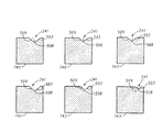
図7は、図5の楕円部501を表すゴルフクラブフェース202の一部の上面図である。図7には、楕円部501における3つの断面を組とする2組が示されている。図7の断面741,742,743は、3つの断面の第1組を形成しており、図9に示されている。図7の断面745,745,747は、3つの断面の第2組を形成しており、図9に示されている。断面741,745は、楕円部501の領域707の断面である。断面742,746は、楕円部501の領域706の断面である。同様に、断面743,747は、楕円部501の領域705の断面である。
FIG. 7 is a top view of a portion of the golf club face 202 representing the
図9に示されているように、断面741,742,743はお互いに実質的に相似であり、かつ、それぞれが対称である。断面741は、領域707の側壁503の上部縁(トップエッジ)に対して垂直であり、断面742は領域706の側壁503の上部縁に対して垂直である。同様に、断面743は、領域705の側壁503の上部縁に対して垂直である。
As shown in FIG. 9, the
一方で、図9に示されるように、断面745,746,747はお互いに実質的に相似ではないが、それぞれが対称である。断面745は領域707の底508に対して垂直であり、断面746は領域706の底508に対して垂直である。同様に、断面747は、領域705の底508に対して垂直である。
On the other hand, as shown in FIG. 9, the
図5に関連して図7に開示される一例の断面は、図6で開示されるとともに示される一例にも同様に適用可能である。また、同一の又は他の例において、断面741−743は底508又は側壁509の上部縁に対して垂直ではなく、さらに断面745−747は側壁503又は側壁509の上部縁に対して垂直ではない。
The cross section of the example disclosed in FIG. 7 in connection with FIG. 5 is equally applicable to the example disclosed and shown in FIG. Also, in the same or other examples, the cross section 741-743 is not perpendicular to the top edge of the bottom 508 or
「相似」という用語は、相互の形状の類似性及び例示される参照要素の関係性に関連する。類似する三角形がそれぞれ同じ角度であるが異なる辺の長さを有している場合、そのような類似した三角形は互いに相似である。本願における類似性は、寸法(例えば、側壁の長さ、高さ)は異なるものの、全体形状は類似していることをいう。 The term “similarity” relates to the similarity of shapes to each other and the relationship of the illustrated reference elements. If similar triangles are each at the same angle but have different side lengths, such similar triangles are similar to each other. Similarity in the present application means that although the dimensions (for example, the length and height of the side wall) are different, the overall shapes are similar.
様々な溝の実施形態が本願で検討されているけれども、溝形成工具230(図2及び3)がゴルフクラブフェース220の第1端214から第2端212までのシングルパスで、又はその逆で作動され得ることに留意されたい。図8の参照番号844で示されるように、シングルパスは実質的に直線状の側壁を有する溝を形成する。このような溝は、断面対称な溝の一例を示す。
Although various groove embodiments are contemplated herein, the groove forming tool 230 (FIGS. 2 and 3) is a single pass from the
他の実施形態では、断面が直線状及び/又は曲線状の表面の側壁を含む非対称溝を形成する第1非対称溝形成工具を、例えば、ゴルフクラブフェース220の第1端214から第2端212、またはその逆(例えば、湾曲した側壁849を有する図8の溝の左側部分を形成する)に伸びる第1パスに沿って作動させ、次に、第1非対称溝形成工具とは異なる第2非対称溝形成工具を、第1パスとは反対方向の第2パスに沿って、前記非対称溝内を作動させることで、前述の非対称溝を対称溝に変化させる(例えば、湾曲した側壁849を有する図8の溝の右側部分を形成する)。ツーパスプロセスは、前記したシングルパスプロセスによって形成されるものとは異なる形状及び容量の断面湾曲表面を有する側壁を備えた溝を形成することができる。
In other embodiments, a first asymmetric groove-forming tool that forms an asymmetric groove that includes a side wall with a straight and / or curved surface, for example, from a
上述した少なくとも2つのパス(ツーパス)は、図8において参照番号849で示される実質的に湾曲した側壁を有する溝を形成することができる。他の例では、マルチプルパスによって直線状の壁の溝を形成してもよく、シングルパスによって湾曲した壁の溝を形成してもよい。本願で開示される一例は、様々なゴルフ標準組織及び/又は統治体によって定義されるルール及び/又は標準に則した溝を提供することができるが、全ての例はその場合に限定されるものではない。溝群を形成するときにマルチプルパスを利用することによって、同一の溝の幅及び異なる断面容積の溝群が得られる。これにより、溝のデザイン及び製造において、より柔軟性が得られる。
The at least two passes (two passes) described above can form a groove having a substantially curved sidewall, indicated by
ここで図9に戻る。図9は、図7の異なる9−9線の断面群で得られる楕円溝部の断面図を示す。図9に示される要素は、溝240の1つの例である溝部の一例の断面を示す。断面741−743は、溝の長手方向に沿った断面における溝の類似性ないしは相似性を示している。断面741−743は、側壁503の上部縁に対して垂直である。断面745−747は、溝の長手方向に沿った断面における溝の相違性ないしは非相似性を示している。断面745−747は、底508及び/又は側壁503の上部縁に対して垂直である。
Returning now to FIG. FIG. 9 shows a cross-sectional view of an elliptical groove portion obtained by a cross-sectional group taken along line 9-9 in FIG. The element shown in FIG. 9 shows a cross section of an example of a groove portion which is one example of the
図10及び図11は、一実施形態におけるゴルフクラブヘッド210,1110の正面図をそれぞれ示しており、それぞれがフロントフェース220に溝240,1140を表している。本願で開示される溝形成技術の性質上、溝端は楕円形状を有することとなる。この点に関し、図10及び図11は、ゴルフクラブフェースの表面において先細っている溝端1090,1190を示している。例えば、一例では、図10の溝端1090は、ゴルフクラブヘッド210のレール領域1091に向かって先細る。他の例では、図11の溝端1190はゴルフクラブヘッド1110のソール領域1196に向かって先細る。いくつかの状況では、図11に示される例は、図10に示される例よりも利点を有している。なぜなら、アドレス位置にゴルフクラブヘッドが置かれたときに、図11の溝端1190は、図10の溝端1090よりも人の目に向かって光を反射するのが抑えられるからである。他の状況では、図10に示される例は、図11に示される例よりも利点を有している。なぜなら、ゴルフクラブフェース220の中心よりも第1端212又は第2端214に近い側でゴルフボールをインパクトすると、図10に示される溝端1090は、図11に示される溝端1190よりもゴルフボールをとらえるからである。
FIGS. 10 and 11 show front views of the golf club heads 210 and 1110 in one embodiment, respectively, and represent the
これらの2つの例は上記の形態に限定されるものではなく、他の実施例では他の形態の溝端形状を備え得る。例えば、図10の溝端1090の各々がレール領域1091に向かって先細るのに代えて、ヒール領域212では溝端1090をレール領域1091に向かって先細らせるとともに、トウ領域214では溝端1090をソール領域1096に向かって先細らせてもよく、その逆の構成であってもよい。さらに、図10の溝端1090の一方をレール領域1091に向かって先細らせ、他の溝端1090をソール領域1096に向かって先細らせるのに代えて、上半分の溝端1090をレール領域1091に向かって先細らせ、下半分の溝端1090をソール領域1096に向かって先細らせてもよく、またその逆の構成であってもよい。
These two examples are not limited to the above forms, and other embodiments may have other forms of groove end shapes. For example, instead of each of the groove ends 1090 of FIG. 10 tapering toward the
また、図10に関し、溝端1090を有する溝240は、溝形成装置231(図2及び図3)を利用して、フライス加工、研削、研磨、又は他の切り込みによって形成されてもよい。より具体的には、図2に示されるように、溝端1090を有する溝240をフライス加工、研削、研磨、又は他の切り込みを実施するために、溝240が形成されるクラブヘッド210は、ホーゼル299がほぼ一方の方向(「上」)を向くとともに、溝形成装置231の溝形成工具230がほぼ反対方向(「下」)を向くように、位置決めされる。
Also with reference to FIG. 10, the
図11に関し、溝端1190を有する溝1140には、溝形成装置231(図2及び図3)と同様の装置を利用して、フライス加工、研削、研磨、又は他の切り込みが実施され得る。ただし、溝形成装置231(又は、溝1140を有するクラブヘッド1100)を図2及び図3に示される位置関係から180°回転させた状態で上述の加工を実施する。より具体的には、溝端1190を有する溝1140にフライス加工、研削、研磨、又は他の切り込みを実施するために、溝1140が形成されるクラブヘッド1100は図2に示されるクラブヘッド210の位置関係から180°回転され、クラブヘッド1100のホーゼル299がほぼ「下」向きとなり、溝形成装置230はほぼ「下」向きのままである。他の例では、溝端1190を有する溝1140にフライス加工、研削、研磨、又は他の切り込みを実施するために、溝1140が形成されるクラブヘッド1100は図2に示されるクラブヘッド210の位置関係と同じであるけれども、溝形成装置231は図2に示される位置関係から180°回転され、溝形成装置231の溝形成工具230はほぼ「上」向きとなる。
Referring to FIG. 11, the
図12は、ゴルフクラブフェース1220の一部の断面図に接触する溝形成工具1230の拡大図である。溝形成工具1230は、溝形成工具230(図2及び図3)及び溝形成工具430(図4)に類似している。例えば、溝形成工具1230は、回転軸1252と回転方向1250を備えており、それらは図3及び図4の回転軸352及び回転方向350にそれぞれ類似している。溝形成工具1230はまた、1つ以上の接触先端1280を備えており、これは図4の接触先端480に類似している。
FIG. 12 is an enlarged view of the
溝形成工具1230は、ゴルフクラブフェース1220にフライス加工、研削、研磨、又は他の切り込みを実施する。溝1240及びゴルフクラブフェース1220は、図2の溝240及びゴルフクラブフェース220にそれぞれ類似し得る。溝1240は、角度1241の側壁を備えており、その角度1241はゴルフクラブフェース1220に対する垂直線から測定される。溝1240を形成するために、溝形成工具1230の回転軸1252は、ゴルフクラブフェース1220に対して角度1260とすることができる。角度1260は、回転軸1252とゴルフクラブフェース1220の間で測定される。角度1260はまた、回転軸1252と接触先端1280の最先端に位置する表面との間で測定することができる。一例では、溝形成工具1230は、ゴルフクラブフェース1220に対して位置決めされ、接触先端1280の最先端の表面は、ゴルフクラブフェース1220に対して平行である。
The
図13及び図14を用いてより具体的に説明されるように、一例では、角度1241,1260はそれぞれ略20°とすることができ、他の例では、角度1241,1260はそれぞれ略5°とすることができる。他の例では、角度1241,1260はそれぞれ、略2°と略43°の間とすることができる。
As described in more detail with reference to FIGS. 13 and 14, in one example, the
図13は、溝形成工具1330の側面図を示しており、図12の溝形成工具1230の一例である。溝形成工具1330は、1つ以上の接触先端1380を備えており、その接触先端は図12の接触先端1280に類似している。1つ以上の接触先端1380を形成する溝形成工具1330の一部は、連続した円盤としてもよく、1つ以上のスパイク(先が尖った部分)を有していてもよく、又は、軸又は中心部から伸びる他の突出部を有していてもよい。
FIG. 13 shows a side view of the
溝形成工具1330はまた、角度1360,1383,1384を備えている。角度1360は、図13に示されるように、溝形成工具1330の回転軸1252と接触先端1380の最先端の表面との間で測定される。角度1360は、角度1260(図12)と略同一である。なぜなら、ゴルフクラブフェースに溝を形成するために溝形成工具1330が使われたときに、接触先端1380の最先端の表面は、ゴルフクラブフェースの表面に対して略平行に位置決めされ得るからである。角度1383は、溝形成工具1330の回転軸1252と溝形成工具1330の表面との間で測定される。ここで、溝形成工具1330の表面は、図13に示されるように、接触先端1380の側面を画定している。角度1384は、図13に示されるように、接触先端1380の対向する側面を画定する溝形成工具1330の2つの表面の間で測定される。一例では、角度1360は略20°であり、角度1383は略90°であり、角度1384は略40°である。この例では、ゴルフクラブフェースの溝の角度1241(図12)は、略20°である。
Groove forming
図14は、溝形成工具1430の側面図であり、図12の溝形成工具1230の実施形態の一例である。図12の溝形成工具1230は、図13及び図14に記載される態様に限定されるものではない。
14 is a side view of the
溝形成工具1430は、1つ以上の接触先端1480を備えており、その接触先端1480は図12の接触先端1280に類似している。1つ以上の接触先端1480を形成する溝形成工具1430の一部は、連続した円盤としてもよく、1つ以上のスパイク(先が尖った部分)を有していてもよく、又は、軸又は中心部から伸びる他の突出部を有していてもよい。溝形成工具1430はまた角度1460,1483,1484を備えており、それらの角度は図13の角度1360,1383,1384と同様である。一実施例では、角度1460は略5°であり、角度1483は略90°であり、角度1484は略10°である。この実施例では、ゴルフクラブフェースに形成された溝の角度1241(図12)は略5°である。
The
ゴルフクラブの製造方法及び物に係る一例の開示は、ゴルフクラブの製造方法及び品物に係る権利範囲を例示することを意図したものであり、なんら限定を加える意図ではない。例えば、一例では、ゴルフクラブヘッド及びその製造方法は、図5−7及び図9−11を参照して開示される特徴とともに、又はそれら特徴とは別に、図2及び図3の1つ以上の特徴を有することができる。同様に、他の例では、ゴルフクラブが図7,9−11の特徴とともに、又はそれら特徴とは別に、図5又は図6の1つ以上の特徴を有することができる。同様に、他の例では、ゴルフクラブが図7,9−11の特徴とともに、又はそれら特徴とは別に、図3又は図4の1つ以上の特徴を有することができる。ゴルフクラブの製造方法及び物の権利範囲は、添付した請求項で請求される範囲にのみ限定されることを意図している。 The disclosure of an example of a golf club manufacturing method and product is intended to exemplify the scope of rights related to the golf club manufacturing method and product, and is not intended to be limiting in any way. For example, in one example, a golf club head and method of manufacture thereof may include one or more of the features of FIGS. 2 and 3 in conjunction with or separate from the features disclosed with reference to FIGS. 5-7 and 9-11. Can have features. Similarly, in other examples, a golf club may have one or more of the features of FIG. 5 or FIG. 6 in conjunction with or separate from the features of FIGS. Similarly, in other examples, a golf club may have one or more of the features of FIG. 3 or FIG. 4 in conjunction with or separate from the features of FIGS. It is intended that the scope of rights of golf club manufacturing methods and objects be limited only to the scope claimed in the appended claims.
ここで検討される物、システム、及び方法は、様々な実施形態で具現化され得る。これら実施形態の上記した検討は、見込まれる全ての実施形態を完全に記述していない。むしろ、詳細な図面の記載、及び図面自身が、ゴルフクラブ及び製造方法に係る少なくとも一つの好ましい実施形態を開示しており、ゴルフクラブ及び製造方法に係る代替の実施形態を開示し得る。 The objects, systems, and methods discussed herein may be embodied in various embodiments. The above discussion of these embodiments does not fully describe all possible embodiments. Rather, the detailed description of the drawings, and the drawings themselves, disclose at least one preferred embodiment of a golf club and manufacturing method, and may disclose alternative embodiments of a golf club and manufacturing method.
特定の請求項で請求された全ての要素は、その特定の請求項において請求されているゴルフクラブ又は製造方法にとって必須のものである。このため、1つ又は複数のクレームされた要素の置換は、再構築するものであって、修繕するものではない。加えて、有益性、他の有用性及び課題の解決方法は、特定の実施形態に関して記載されている。しかしながら、それらの有益性、有用性、課題の解決方法及びそれらの有益性、有用性及び課題の解決方法をもたらし得る、又はそれらをより明示する如何なる要素も、いずれの又はすべての請求項の、必須、必要、又は本質的な要素であるとして解釈されるべきではない。
All elements claimed in any particular claim are essential to the golf club or method of manufacture claimed in that particular claim. Thus, the replacement of one or more claimed elements is a reconstruction and not a repair. In addition, benefits, other utilities, and solutions to problems have been described with regard to specific embodiments. However, any element that may or may more clearly define their benefit, utility, method of solving the problem and solution of those benefits, utility, and problem of any or all claims, Should not be construed as essential, necessary or essential.
Claims (31)
ゴルフクラブフェースを有するゴルフクラブヘッドを用意する工程と、
ゴルフクラブフェースに溝を形成する溝形成工程と、を備えており、
前記溝形成工程は、
ゴルフフェースに対して実質的に0°よりも大きく、且つ実質的に90°よりも小さな角度の回転軸回りに溝形成工具を回転させる工程と、
前記角度において、ゴルフクラブフェースの第1端から第2端まで溝形成工具を移動させる工程と、を有する製造方法。 A method of manufacturing a golf club head comprising:
Providing a golf club head having a golf club face;
A groove forming step of forming a groove in the golf club face,
The groove forming step includes
Rotating the grooving tool about a rotation axis at an angle substantially greater than 0 ° and substantially less than 90 ° relative to the golf face;
Moving the groove-forming tool from the first end to the second end of the golf club face at the angle.
第1側壁はゴルフクラブフェースに第1末端を備えており、第2側壁はゴルフクラブフェースに第2末端を備えており、
第1末端と第2末端は非平行である請求項2に記載の製造方法。 The ellipse has a first side wall and a second side wall,
The first side wall has a first end on the golf club face, the second side wall has a second end on the golf club face,
The manufacturing method according to claim 2, wherein the first end and the second end are non-parallel.
楕円部の第1領域における断面であって、溝の第1領域の第1側壁の縁に対して垂直である第1断面と、
楕円部の第2領域における断面であって、溝の第2領域の第1側壁の縁に対して垂直である第2断面と、
楕円部の第1領域における断面であって、溝の第1領域の底に対して垂直である第3断面と、
楕円部の第2領域における断面であって、溝の第2領域の底に対して垂直である第4断面と、を備えており、
第1断面は対称であり、
第1断面は第2断面に実質的に相似であり、
第2断面は対称であり、
第3断面は対称であり、
第3断面は第4断面に実質的に非相似であり、
第4断面は対称である請求項2〜4のいずれか一項に記載の製造方法。 The groove of the golf club face
A first cross section in a first region of the ellipse, which is perpendicular to the edge of the first sidewall of the first region of the groove;
A second cross section in the second region of the ellipse, the second cross section being perpendicular to the edge of the first sidewall of the second region of the groove;
A third cross section in the first region of the ellipse, which is perpendicular to the bottom of the first region of the groove;
A cross section in the second region of the ellipse, the fourth cross section being perpendicular to the bottom of the second region of the groove,
The first cross section is symmetrical;
The first cross section is substantially similar to the second cross section;
The second cross section is symmetrical;
The third cross section is symmetric,
The third cross section is substantially dissimilar to the fourth cross section;
The manufacturing method according to any one of claims 2 to 4, wherein the fourth cross section is symmetrical.
溝形成工具をゴルフクラブフェースの第1端から第2端までシングルパスで移動させる工程を有する請求項1〜5のいずれか一項に記載の製造方法。 The step of moving the groove forming tool further includes:
The manufacturing method according to claim 1, further comprising a step of moving the groove forming tool from the first end to the second end of the golf club face in a single pass.
異なる溝形成工具をゴルフクラブフェースの第1端から第2端まで少なくとも2つのパスで移動させる工程を有する請求項1〜5のいずれか一項に記載の製造方法。 The step of moving the groove forming tool further includes:
The manufacturing method according to claim 1, further comprising a step of moving different groove forming tools from the first end to the second end of the golf club face in at least two passes.
ゴルフクラブフェースとの接触先端において実質的に一定の速度で溝形成工具を回転させる工程を有する請求項1〜9のいずれか一項に記載の製造方法。 The step of rotating the groove forming tool,
The manufacturing method according to claim 1, further comprising a step of rotating the groove forming tool at a substantially constant speed at a contact tip with the golf club face.
ゴルフクラブフェースに対して約2°から約43°の範囲内の角度に固定する工程を備えている請求項1〜11のいずれか一項に記載の製造方法。 The step of rotating the groove forming tool,
The manufacturing method according to claim 1, further comprising a step of fixing the golf club face at an angle within a range of about 2 ° to about 43 °.
約45表面メートル/分から約800表面メートル/分の範囲内の速度で溝形成工具を回転させる工程を有する請求項1〜12のいずれか一項に記載の製造方法。 The step of rotating the groove forming tool,
13. A method according to any one of the preceding claims, comprising rotating the grooving tool at a speed in the range of about 45 surface meters / minute to about 800 surface meters / minute.
ゴルフクラブフェースを有するゴルフクラブヘッドを用意する工程と、
ゴルフクラブフェースに複数の平行溝を形成する平行溝形成工程と、
ゴルフクラブヘッドにシャフトを結合させる工程と、を備えており、
前記平行溝形成工程は、
ゴルフクラブフェースに対して実質的に0°よりも大きく、且つ実質的に90°よりも小さな角度で回転軸回りに溝形成工具を回転させる工程と、
その角度において、ゴルフクラブフェースの第1端から第2端まで溝形成工具を移動させる工程、を有する製造方法。 A method for manufacturing a golf club, comprising:
Providing a golf club head having a golf club face;
A parallel groove forming step of forming a plurality of parallel grooves on the golf club face;
And a step of coupling a shaft to the golf club head,
The parallel groove forming step includes
Rotating the grooving tool about an axis of rotation at an angle substantially greater than 0 ° and substantially less than 90 ° relative to the golf club face;
And a step of moving the groove forming tool from the first end to the second end of the golf club face at the angle.
ゴルフクラブフェースとの接触先端において実質的に一定の速度で溝形成工具を回転させる工程を有する請求項18に記載の製造方法。 The step of rotating the groove forming tool,
The manufacturing method according to claim 18, further comprising a step of rotating the groove forming tool at a substantially constant speed at a contact tip with the golf club face.
約90表面メートル/分から約300表面メートル/分の範囲内の速度で溝形成工具を回転させる工程を有する請求項18又は19に記載の製造方法。 The step of rotating the groove forming tool,
20. A method according to claim 18 or 19, comprising the step of rotating the grooving tool at a speed in the range of about 90 surface meters / minute to about 300 surface meters / minute.
溝形成工具をゴルフクラブフェースの第1端から第2端までシングルパスで移動させ、複数の平行溝の1つを形成する工程を有する請求項18〜20のいずれか一項に記載の製造方法。 The step of moving the groove forming tool further includes:
The manufacturing method according to any one of claims 18 to 20, further comprising a step of moving the groove forming tool from a first end to a second end of the golf club face in a single pass to form one of the plurality of parallel grooves. .
複数の溝を有するゴルフクラブフェースを備えており、
複数の溝のうちの1つにおける第1端の第1領域における第1断面が第1端の第1領域の側壁の縁に垂直であり、第1端の第2領域における第2断面が第1端の第2領域の側壁の縁に対して垂直であり、第1断面が第2断面に対して実質的に相似であり、第1断面と第2断面はそれぞれ対称であり、
第1端の第1領域における第3断面が第1端の第1領域の底に対して垂直であり、第1端の第2領域における第4断面が第1端の第2領域の底に対して垂直であり、第3断面が第4断面に対して実質的に非相似であり、第3断面と第4断面はそれぞれ対称であるゴルフクラブヘッド。 A golf club head,
A golf club face having a plurality of grooves;
The first cross section in the first region of the first end in one of the plurality of grooves is perpendicular to the edge of the side wall of the first region of the first end, and the second cross section in the second region of the first end is the first cross section. The first section is perpendicular to the edge of the side wall of the second region, the first section is substantially similar to the second section, and the first section and the second section are each symmetrical;
The third cross section in the first region at the first end is perpendicular to the bottom of the first region at the first end, and the fourth cross section in the second region at the first end is at the bottom of the second region at the first end. A golf club head perpendicular to the third cross section, wherein the third cross section is substantially dissimilar to the fourth cross section, and the third cross section and the fourth cross section are symmetrical.
第1側壁はゴルフクラブフェースに第1末端を有しており、第2側壁はゴルフクラブフェースに第2末端を有しており、
第1末端と第2末端はお互いに非平行である請求項27に記載のゴルフクラブヘッド。 The ellipse has a first side wall and a second side wall,
The first side wall has a first end on the golf club face, the second side wall has a second end on the golf club face,
28. A golf club head according to claim 27, wherein the first end and the second end are non-parallel to each other.
30. The golf club head according to any one of claims 23 to 29, wherein the plurality of grooves taper toward a sole of the golf club head.
Applications Claiming Priority (4)
| Application Number | Priority Date | Filing Date | Title |
|---|---|---|---|
| US2920508P | 2008-02-15 | 2008-02-15 | |
| US61/029,205 | 2008-02-15 | ||
| US12/189,606 | 2008-08-11 | ||
| US12/189,606 US7905798B2 (en) | 2008-02-15 | 2008-08-11 | Golf club head and method of manufacturing |
Publications (3)
| Publication Number | Publication Date |
|---|---|
| JP2009189818A true JP2009189818A (en) | 2009-08-27 |
| JP2009189818A5 JP2009189818A5 (en) | 2012-03-15 |
| JP5219875B2 JP5219875B2 (en) | 2013-06-26 |
Family
ID=40955646
Family Applications (1)
| Application Number | Title | Priority Date | Filing Date |
|---|---|---|---|
| JP2009030518A Expired - Fee Related JP5219875B2 (en) | 2008-02-15 | 2009-02-12 | Golf club head and manufacturing method thereof |
Country Status (3)
| Country | Link |
|---|---|
| US (3) | US7905798B2 (en) |
| JP (1) | JP5219875B2 (en) |
| CN (1) | CN101537247B (en) |
Cited By (2)
| Publication number | Priority date | Publication date | Assignee | Title |
|---|---|---|---|---|
| US20110200407A1 (en) * | 2008-02-15 | 2011-08-18 | Petersen David L | Groove Forming Machine for Manufacturing Golf Club Head |
| JP2019150639A (en) * | 2011-09-30 | 2019-09-12 | カーステン マニュファクチュアリング コーポレーション | Grooves of golf club heads and methods of manufacturing grooves of golf club heads |
Families Citing this family (18)
| Publication number | Priority date | Publication date | Assignee | Title |
|---|---|---|---|---|
| US7918747B2 (en) * | 2004-07-30 | 2011-04-05 | New Text | Golf club head having a grooved face |
| US7758449B2 (en) * | 2003-12-12 | 2010-07-20 | Acushnet Company | Golf club head having a grooved and textured face |
| US8752271B2 (en) | 2004-07-30 | 2014-06-17 | Acushnet Company | Golf club groove configuration |
| JP5601830B2 (en) * | 2009-12-21 | 2014-10-08 | ブリヂストンスポーツ株式会社 | Manufacturing method of golf club head |
| JP5866969B2 (en) * | 2011-10-27 | 2016-02-24 | ブリヂストンスポーツ株式会社 | Golf club head and manufacturing method thereof |
| US9050509B2 (en) * | 2012-04-03 | 2015-06-09 | Karsten Manufacturing Corporation | Golf club heads and methods of manufacturing golf club heads |
| US9987529B2 (en) | 2012-04-03 | 2018-06-05 | Karsten Manufacturing Corporation | Golf club heads and methods of manufacturing golf club heads |
| CN102974874B (en) * | 2012-11-21 | 2015-08-19 | 东莞亿诚精密模具有限公司 | The processing method of a kind of golf iron scope of attack and scope of attack duct |
| TWI483758B (en) * | 2013-09-30 | 2015-05-11 | Fusheng Prec Co Ltd | Manufacturing method of steel golf head with active metal |
| US9636757B1 (en) | 2014-09-23 | 2017-05-02 | Callaway Golf Company | Golf club head with face grooves and texturing |
| CN104526260A (en) * | 2014-11-26 | 2015-04-22 | 柳州瑞明威罗动力机械有限公司 | Processing method of thrust groove |
| US9844709B2 (en) * | 2015-09-24 | 2017-12-19 | Acushnet Company | Golf club striking surface |
| US9868037B1 (en) * | 2016-07-26 | 2018-01-16 | Dunlop Sports Co., Ltd. | Golf club head with textured striking face |
| US10682555B2 (en) | 2016-07-26 | 2020-06-16 | Sumitomo Rubber Industries, Ltd. | Golf club head with textured striking face |
| US10874915B2 (en) | 2017-08-10 | 2020-12-29 | Taylor Made Golf Company, Inc. | Golf club heads |
| US11701557B2 (en) | 2017-08-10 | 2023-07-18 | Taylor Made Golf Company, Inc. | Golf club heads |
| US20220379176A1 (en) * | 2021-05-27 | 2022-12-01 | Acushnet Company | Forged golf club head with improved scorelines |
| US20220379367A1 (en) * | 2021-05-27 | 2022-12-01 | Acushnet Company | Forged golf club head with improved scorelines |
Citations (5)
| Publication number | Priority date | Publication date | Assignee | Title |
|---|---|---|---|---|
| JPH11178960A (en) * | 1997-12-18 | 1999-07-06 | Mizuno Corp | Golf head |
| JP2000296191A (en) * | 1999-04-16 | 2000-10-24 | Daiwa Seiko Inc | Golf club head |
| JP2002224250A (en) * | 2000-12-27 | 2002-08-13 | Dunlop Slazenger Group Amercas | Gold club providing improved spin and method of manufacturing for the same |
| JP2005169129A (en) * | 2003-12-12 | 2005-06-30 | Acushnet Co | Golf club spin milling grooves |
| JP2005287534A (en) * | 2004-03-31 | 2005-10-20 | Sri Sports Ltd | Golf club head and golf club provided with it |
Family Cites Families (61)
| Publication number | Priority date | Publication date | Assignee | Title |
|---|---|---|---|---|
| US1675437A (en) * | 1927-08-04 | 1928-07-03 | Frederick A Waldron | Method of and apparatus for shaping golf-club faces and club produced thereby |
| US2767749A (en) * | 1955-03-01 | 1956-10-23 | Spalding A G & Bros Inc | Machine for shaping golf club heads |
| US3908722A (en) * | 1974-04-30 | 1975-09-30 | William H Jacobs | Golf club head facing apparatus |
| US4631993A (en) * | 1978-10-05 | 1986-12-30 | General Electric Company | Grooving tool and method for making same |
| US4233867A (en) * | 1978-12-05 | 1980-11-18 | General Electric Company | Multiple insert tool assembly for threading, grooving and the like |
| US4750537A (en) * | 1986-11-14 | 1988-06-14 | Herbert Green | Universal golf wood facing machine and method |
| US4957294A (en) * | 1987-06-24 | 1990-09-18 | Macgregor Golf Company | Golf club head |
| US4766698A (en) * | 1987-11-16 | 1988-08-30 | Alexander Solomko | Apparatus for finishing the face of the head of a golf club wood |
| FR2657531A1 (en) | 1990-01-31 | 1991-08-02 | Salomon Sa | GOLF CLUB HEAD. |
| US5354059A (en) * | 1990-02-02 | 1994-10-11 | Stuff Alfred O | Golf club heads with means for imparting corrective action |
| US5029864A (en) * | 1990-06-11 | 1991-07-09 | Keener Michael B | Golf club head with grooved striking face |
| US5163682A (en) * | 1990-10-16 | 1992-11-17 | Callaway Golf Company | Metal wood golf club with variable faceplate thickness |
| JPH05317463A (en) * | 1992-05-27 | 1993-12-03 | Bridgestone Corp | Golf club set |
| US5437088A (en) * | 1993-01-19 | 1995-08-01 | Igarashi; Lawrence Y. | Method of making a golf club that provides enhanced backspin and reduced sidespin |
| US5358249A (en) * | 1993-07-06 | 1994-10-25 | Wilson Sporting Goods Co. | Golf club with plurality of inserts |
| WO1995006501A1 (en) * | 1993-08-31 | 1995-03-09 | Sheehan, John, Patrick | Process for making metal wood club heads |
| US5595547A (en) * | 1995-03-10 | 1997-01-21 | Lekavich; Carl W. | Matched golf club set having V-shaped grooves that change from club to club |
| US5709617A (en) * | 1995-07-27 | 1998-01-20 | The Yokohama Rubber Co., Ltd. | Wood type golf club head |
| JPH0970457A (en) * | 1995-09-04 | 1997-03-18 | Bridgestone Sports Co Ltd | Golf club |
| JPH09192274A (en) * | 1996-01-23 | 1997-07-29 | Sumitomo Rubber Ind Ltd | Golf club set |
| JP3000921B2 (en) * | 1996-03-25 | 2000-01-17 | 株式会社遠藤製作所 | Golf club and manufacturing method thereof |
| JPH10225539A (en) * | 1997-02-13 | 1998-08-25 | Bridgestone Sports Co Ltd | Golf club head |
| JP3901788B2 (en) * | 1997-03-07 | 2007-04-04 | ブリヂストンスポーツ株式会社 | Golf club head |
| US6007434A (en) | 1998-04-06 | 1999-12-28 | Hustler Golf Company | Golf club |
| US6048277A (en) | 1998-07-13 | 2000-04-11 | Raymond; David | Golf club head having upwardly directed and opposing, oblique score lines |
| JP2000176058A (en) * | 1998-12-14 | 2000-06-27 | Yokohama Rubber Co Ltd:The | Golf club head |
| JP3579614B2 (en) * | 1999-04-23 | 2004-10-20 | 住友ゴム工業株式会社 | Golf club head and manufacturing method thereof |
| JP2000350799A (en) * | 1999-06-10 | 2000-12-19 | Fujitsu Sinter Ltd | Golf iron club |
| US6443856B1 (en) * | 1999-11-01 | 2002-09-03 | Callaway Golf Company | Contoured scorelines for the face of a golf club |
| JP2001178856A (en) * | 1999-12-27 | 2001-07-03 | Sumitomo Rubber Ind Ltd | Golf club head |
| US6398665B1 (en) * | 2000-02-23 | 2002-06-04 | Anthony J. Antonious | Golf club with unique ball striking face configuration |
| US6981923B2 (en) * | 2000-05-09 | 2006-01-03 | Dunlop Sports | High spin golf club groove configuration |
| JP2002153575A (en) * | 2000-11-20 | 2002-05-28 | Mizuno Corp | Golf club with ultra-fine processing on the face |
| JP2002159601A (en) * | 2000-11-28 | 2002-06-04 | Daiwa Seiko Inc | Wood golf club head |
| JP2002239040A (en) * | 2001-02-20 | 2002-08-27 | Sumitomo Rubber Ind Ltd | Golf club head |
| US6733400B2 (en) | 2001-04-20 | 2004-05-11 | U.I.G., Inc. | Gold club iron head, correlated set of individually numbered golf club irons, method of matching a golf club to a golfer, and method of matching a set of golf clubs to a golfer |
| US20030134687A1 (en) * | 2002-01-11 | 2003-07-17 | Truesdale Gary N. | Multi-use golf club head |
| US6814673B2 (en) * | 2002-11-01 | 2004-11-09 | Taylor Made Golf Company, Inc. | Golf club head having improved grooves |
| US6904663B2 (en) * | 2002-11-04 | 2005-06-14 | Taylor Made Golf Company, Inc. | Method for manufacturing a golf club face |
| US20050043113A1 (en) | 2003-01-24 | 2005-02-24 | Mann James A. | Variable scoreline golf club groove configuration |
| US7846039B2 (en) | 2003-08-13 | 2010-12-07 | Acushnet Company | Golf club head |
| US7594862B2 (en) * | 2003-08-13 | 2009-09-29 | Acushnet Company | Golf club head |
| US6813821B1 (en) * | 2003-08-14 | 2004-11-09 | Wen-Cheng Tseng | Manufacturing method for a golf club head |
| US7976405B2 (en) * | 2003-12-12 | 2011-07-12 | Acushnet Company | Golf club groove configuration |
| US7918747B2 (en) * | 2004-07-30 | 2011-04-05 | New Text | Golf club head having a grooved face |
| US7568983B2 (en) | 2004-07-30 | 2009-08-04 | Acushnet Company | Golf club head groove configuration |
| US7056226B2 (en) * | 2003-12-30 | 2006-06-06 | Callaway Golf Company | Golf club having stepped grooves |
| JP2005270517A (en) * | 2004-03-26 | 2005-10-06 | Mizuno Corp | Golf club head, method for manufacturing the same, and golf club |
| FR2872723B1 (en) * | 2004-07-12 | 2006-09-08 | Seco Tools Ab | MACHINING TOOL, IN PARTICULAR FOR FORMING A CONICAL SURFACE |
| JP2008005994A (en) * | 2006-06-28 | 2008-01-17 | Sri Sports Ltd | Iron type golf club head |
| JP5170992B2 (en) * | 2006-07-24 | 2013-03-27 | ブリヂストンスポーツ株式会社 | Golf club head |
| JP4917415B2 (en) * | 2006-11-28 | 2012-04-18 | ブリヂストンスポーツ株式会社 | Golf club head |
| JP4933232B2 (en) * | 2006-11-30 | 2012-05-16 | ブリヂストンスポーツ株式会社 | Golf club head |
| US7815521B2 (en) * | 2006-12-01 | 2010-10-19 | Bridgestone Sports, Co., Ltd. | Golf club head |
| JP5380634B2 (en) * | 2007-07-24 | 2014-01-08 | ブリヂストンスポーツ株式会社 | Golf club head manufacturing method and golf club head |
| JP5296344B2 (en) * | 2007-08-02 | 2013-09-25 | ブリヂストンスポーツ株式会社 | Golf club head manufacturing method and golf club head |
| US20090082129A1 (en) * | 2007-09-26 | 2009-03-26 | Bridgestone Sports Co., Ltd. | Method of Manufacturing Golf Club Head and Golf Club Head |
| JP2009153922A (en) * | 2007-12-27 | 2009-07-16 | Daiwa Seiko Inc | Golf club |
| US7905798B2 (en) * | 2008-02-15 | 2011-03-15 | Karsten Manufacturing Corporation | Golf club head and method of manufacturing |
| US7819756B2 (en) * | 2008-04-01 | 2010-10-26 | Bridgestone Sports Co., Ltd. | Golf club head |
| US7927230B2 (en) * | 2008-10-31 | 2011-04-19 | Karsten Manufacturing Corporation | Golf club head with grooves and method of manufacture |
-
2008
- 2008-08-11 US US12/189,606 patent/US7905798B2/en active Active
-
2009
- 2009-02-12 JP JP2009030518A patent/JP5219875B2/en not_active Expired - Fee Related
- 2009-02-16 CN CN2009100095142A patent/CN101537247B/en active Active
-
2010
- 2010-04-22 US US12/765,556 patent/US8167738B2/en active Active
-
2011
- 2011-04-25 US US13/093,432 patent/US8578980B2/en active Active
Patent Citations (5)
| Publication number | Priority date | Publication date | Assignee | Title |
|---|---|---|---|---|
| JPH11178960A (en) * | 1997-12-18 | 1999-07-06 | Mizuno Corp | Golf head |
| JP2000296191A (en) * | 1999-04-16 | 2000-10-24 | Daiwa Seiko Inc | Golf club head |
| JP2002224250A (en) * | 2000-12-27 | 2002-08-13 | Dunlop Slazenger Group Amercas | Gold club providing improved spin and method of manufacturing for the same |
| JP2005169129A (en) * | 2003-12-12 | 2005-06-30 | Acushnet Co | Golf club spin milling grooves |
| JP2005287534A (en) * | 2004-03-31 | 2005-10-20 | Sri Sports Ltd | Golf club head and golf club provided with it |
Cited By (3)
| Publication number | Priority date | Publication date | Assignee | Title |
|---|---|---|---|---|
| US20110200407A1 (en) * | 2008-02-15 | 2011-08-18 | Petersen David L | Groove Forming Machine for Manufacturing Golf Club Head |
| US8578980B2 (en) * | 2008-02-15 | 2013-11-12 | Karsten Manufacturing Corporation | Groove forming machine for manufacturing golf club head |
| JP2019150639A (en) * | 2011-09-30 | 2019-09-12 | カーステン マニュファクチュアリング コーポレーション | Grooves of golf club heads and methods of manufacturing grooves of golf club heads |
Also Published As
| Publication number | Publication date |
|---|---|
| US7905798B2 (en) | 2011-03-15 |
| CN101537247A (en) | 2009-09-23 |
| US20110200407A1 (en) | 2011-08-18 |
| US20090209362A1 (en) | 2009-08-20 |
| US8167738B2 (en) | 2012-05-01 |
| CN101537247B (en) | 2012-12-26 |
| US8578980B2 (en) | 2013-11-12 |
| US20100210375A1 (en) | 2010-08-19 |
| JP5219875B2 (en) | 2013-06-26 |
Similar Documents
| Publication | Publication Date | Title |
|---|---|---|
| JP5219875B2 (en) | Golf club head and manufacturing method thereof | |
| JP5296344B2 (en) | Golf club head manufacturing method and golf club head | |
| JP5380634B2 (en) | Golf club head manufacturing method and golf club head | |
| JP2009189818A5 (en) | ||
| US9604285B2 (en) | Rotary tool and method for manufacturing | |
| KR101995590B1 (en) | A polygonal turning insert | |
| CN104959667B (en) | Knife face band Unequal distance arc head milling cutter and method for grinding after a kind of eccentric shape | |
| CN103285566A (en) | Golf club head | |
| US8602911B2 (en) | Golf club heads with grooves and methods of manufacture | |
| TW201615311A (en) | Rotary milling tool | |
| WO2012157063A1 (en) | Drill head for deep hole cutting | |
| JP4995228B2 (en) | Manufacturing method of golf club head | |
| CN102933350A (en) | Method of manufacturing formed cutter and grinding tool for formed cutter | |
| CN109475954A (en) | Gear cutting tool | |
| RU2532205C2 (en) | Drill, method and device for its fabrication | |
| JP2015093130A (en) | Manufacturing method | |
| JP6600168B2 (en) | Production method | |
| KR20120044059A (en) | End-mill | |
| JP2011194479A (en) | Drill head for cutting deep hole | |
| CN114101757B (en) | Double-edge cutter and machining method thereof | |
| JP6116180B2 (en) | Manufacturing method and golf club head | |
| JP2007245338A (en) | Milling cutter | |
| JP6519091B2 (en) | End mill | |
| CN103084596A (en) | Cutter for turning driving rod of nuclear power station | |
| KR20130000841U (en) | Chamfering cutter |
Legal Events
| Date | Code | Title | Description |
|---|---|---|---|
| A521 | Request for written amendment filed |
Free format text: JAPANESE INTERMEDIATE CODE: A523 Effective date: 20120126 |
|
| A621 | Written request for application examination |
Free format text: JAPANESE INTERMEDIATE CODE: A621 Effective date: 20120126 |
|
| A131 | Notification of reasons for refusal |
Free format text: JAPANESE INTERMEDIATE CODE: A131 Effective date: 20121113 |
|
| A977 | Report on retrieval |
Free format text: JAPANESE INTERMEDIATE CODE: A971007 Effective date: 20121115 |
|
| A521 | Request for written amendment filed |
Free format text: JAPANESE INTERMEDIATE CODE: A523 Effective date: 20130115 |
|
| TRDD | Decision of grant or rejection written | ||
| A01 | Written decision to grant a patent or to grant a registration (utility model) |
Free format text: JAPANESE INTERMEDIATE CODE: A01 Effective date: 20130212 |
|
| A61 | First payment of annual fees (during grant procedure) |
Free format text: JAPANESE INTERMEDIATE CODE: A61 Effective date: 20130305 |
|
| FPAY | Renewal fee payment (event date is renewal date of database) |
Free format text: PAYMENT UNTIL: 20160315 Year of fee payment: 3 |
|
| R150 | Certificate of patent or registration of utility model |
Ref document number: 5219875 Country of ref document: JP Free format text: JAPANESE INTERMEDIATE CODE: R150 Free format text: JAPANESE INTERMEDIATE CODE: R150 |
|
| R250 | Receipt of annual fees |
Free format text: JAPANESE INTERMEDIATE CODE: R250 |
|
| R250 | Receipt of annual fees |
Free format text: JAPANESE INTERMEDIATE CODE: R250 |
|
| R250 | Receipt of annual fees |
Free format text: JAPANESE INTERMEDIATE CODE: R250 |
|
| R250 | Receipt of annual fees |
Free format text: JAPANESE INTERMEDIATE CODE: R250 |
|
| R250 | Receipt of annual fees |
Free format text: JAPANESE INTERMEDIATE CODE: R250 |
|
| R250 | Receipt of annual fees |
Free format text: JAPANESE INTERMEDIATE CODE: R250 |
|
| R250 | Receipt of annual fees |
Free format text: JAPANESE INTERMEDIATE CODE: R250 |
|
| R250 | Receipt of annual fees |
Free format text: JAPANESE INTERMEDIATE CODE: R250 |
|
| R250 | Receipt of annual fees |
Free format text: JAPANESE INTERMEDIATE CODE: R250 |
|
| LAPS | Cancellation because of no payment of annual fees |