JP2009186213A - Gyro sensor unit - Google Patents
Gyro sensor unit Download PDFInfo
- Publication number
- JP2009186213A JP2009186213A JP2008023850A JP2008023850A JP2009186213A JP 2009186213 A JP2009186213 A JP 2009186213A JP 2008023850 A JP2008023850 A JP 2008023850A JP 2008023850 A JP2008023850 A JP 2008023850A JP 2009186213 A JP2009186213 A JP 2009186213A
- Authority
- JP
- Japan
- Prior art keywords
- gyro sensor
- adjustment
- gyro
- vibrator
- voltage
- Prior art date
- Legal status (The legal status is an assumption and is not a legal conclusion. Google has not performed a legal analysis and makes no representation as to the accuracy of the status listed.)
- Pending
Links
- 239000000758 substrate Substances 0.000 claims abstract description 7
- 238000001514 detection method Methods 0.000 description 36
- 238000010586 diagram Methods 0.000 description 4
- 238000004519 manufacturing process Methods 0.000 description 4
- 239000004020 conductor Substances 0.000 description 1
- 239000004065 semiconductor Substances 0.000 description 1
Images


Landscapes
- Gyroscopes (AREA)
Abstract
Description
本発明は、印加された角速度を検出するジャイロセンサユニットに関する。 The present invention relates to a gyro sensor unit that detects an applied angular velocity.
特許文献1のジャイロセンサは、振動子に可動電極を設け、この可動電極と対向する固定電極との間の距離の変化に基づいて振動子に印加される角速度を検出している。また、特許文献1では、一つのジャイロセンサは、二つの振動子を有している。ところで、ジャイロセンサは、半導体製造技術を利用するMEMS(Micro Electro Mechanical SYstems)として形成されている。このようなジャイロセンサは、設計上の所望の駆動周波数に対して、製造工程上の誤差により駆動周波数にばらつきを含んでいる。
しかしながら、ジャイロセンサユニットの冗長性を高めるために、二つのジャイロセンサを用いることがある。この場合、二つのジャイロセンサの駆動周波数が近似しているとき、第1のジャイロセンサの駆動による振動が第2のジャイロセンサに伝達され、また第2のジャイロセンサの駆動による振動が第1のジャイロセンサに伝達され、互いのジャイロセンサの動作に影響を及ぼす可能性がある。具体的には、各ジャイロセンサの駆動周波数の差分に相当する周波数成分が、ジャイロセンサの出力信号に各々ビートノイズとして重畳され、その結果としてジャイロセンサユニットの出力信号にもビートノイズが重畳されて出力される。例えば、二つのジャイロセンサの一方の駆動周波数が1kHzであり、他方の駆動周波数が1.001kHzであるとき、ジャイロセンサユニットの出力値にはその共振周波数の差分である1Hzがビートノイズとして含まれる。このような数Hz程度のビートノイズは、ローパスフィルタによる除去が困難である。特許文献1の場合、ビートノイズ対策ではないものの、フィードバック制御により振動子の駆動周波数を調整している。しかし、フィードバック制御を実施する場合、例えば複雑なフィードバック回路などを必要とし、回路構造などの複雑化を招くという問題がある。 However, in order to increase the redundancy of the gyro sensor unit, two gyro sensors may be used. In this case, when the drive frequencies of the two gyro sensors are approximate, vibration due to the drive of the first gyro sensor is transmitted to the second gyro sensor, and vibration due to the drive of the second gyro sensor is the first. There is a possibility of being transmitted to the gyro sensors and affecting the operation of each other's gyro sensors. Specifically, a frequency component corresponding to the difference in driving frequency of each gyro sensor is superimposed as beat noise on the output signal of the gyro sensor, and as a result, beat noise is also superimposed on the output signal of the gyro sensor unit. Is output. For example, when the drive frequency of one of the two gyro sensors is 1 kHz and the other drive frequency is 1.001 kHz, the output value of the gyro sensor unit includes 1 Hz that is the difference between the resonance frequencies as beat noise. . Such beat noise of about several Hz is difficult to remove by a low-pass filter. In the case of Patent Document 1, although not a measure against beat noise, the drive frequency of the vibrator is adjusted by feedback control. However, when feedback control is performed, there is a problem that, for example, a complicated feedback circuit or the like is required, resulting in a complicated circuit structure or the like.
そこで、本発明の目的は、複数のジャイロセンサを備える場合でも、構造の複雑化を招くことなくビートノイズの除去が容易なジャイロセンサユニットを提供することにある。 Accordingly, an object of the present invention is to provide a gyro sensor unit in which beat noise can be easily removed without complicating the structure even when a plurality of gyro sensors are provided.
請求項1記載の発明では、複数のジャイロセンサの少なくとも一方の駆動周波数を電気的に変更している。例えばジャイロセンサの振動子に印加する電圧などを変化させることにより、振動子の駆動周波数を変化させる。これにより、複数のジャイロセンサの駆動周波数は変化する。そのため、複数のジャイロセンサの共振周波数の差分は拡大する。その結果、共振周波数の差分に対応するビートノイズは、ローパスフィルタによって容易に除去される。したがって、複数のジャイロセンサを備える場合でも、構造の複雑化を招くことなくビートノイズの除去を容易にすることができる。ところで、複数のジャイロセンサの駆動周波数を変更し、共振周波数の差分を拡大させることも考えられる。しかし、この場合、ジャイロセンサごとに個別に設計が必要となり、冗長性の確保に複雑な制御が必要になるとともに、製造工程および構造の複雑化を招く。請求項1記載の発明の場合、同一設計の複数のジャイロセンサを用いることができるので、制御が容易になり、製造工程および構造も簡略化することができる。 In the first aspect of the invention, the drive frequency of at least one of the plurality of gyro sensors is electrically changed. For example, the drive frequency of the vibrator is changed by changing the voltage applied to the vibrator of the gyro sensor. Thereby, the drive frequency of a plurality of gyro sensors changes. Therefore, the difference between the resonance frequencies of the plurality of gyro sensors is increased. As a result, beat noise corresponding to the difference between the resonance frequencies is easily removed by the low-pass filter. Therefore, even when a plurality of gyro sensors are provided, beat noise can be easily removed without complicating the structure. By the way, it is also conceivable to increase the difference between the resonance frequencies by changing the drive frequencies of the plurality of gyro sensors. However, in this case, it is necessary to design each gyro sensor individually, and complicated control is required to ensure redundancy, and the manufacturing process and structure are complicated. In the case of the invention described in claim 1, since a plurality of gyro sensors having the same design can be used, the control becomes easy, and the manufacturing process and structure can be simplified.
請求項2または3記載の発明では、駆動周波数変更手段は回路基板に複数のパッド電極を有している。パッド電極には、ジャイロセンサの駆動周波数を変更するための調整電圧が印加されている。この複数のパッド電極に異なる調整電圧を印加することにより、いずれかのパッド電極と振動子電極とを電気配線部で接続することにより、振動子に印加される調整電圧が変化する。その結果、振動子の駆動周波数が変化する。したがって、簡単な構造でジャイロセンサの駆動周波数を変更することができる。 In the invention according to claim 2 or 3, the drive frequency changing means has a plurality of pad electrodes on the circuit board. An adjustment voltage for changing the drive frequency of the gyro sensor is applied to the pad electrode. By applying different adjustment voltages to the plurality of pad electrodes, any one of the pad electrodes and the vibrator electrode is connected by the electric wiring portion, whereby the adjustment voltage applied to the vibrator changes. As a result, the drive frequency of the vibrator changes. Therefore, the drive frequency of the gyro sensor can be changed with a simple structure.
請求項4記載の発明では、駆動周波数変更手段は回路基板に記憶部を有している。記憶部は、ジャイロセンサの駆動周波数を変更するための調整電圧を記憶している。記憶部に記憶されている調整電圧に基づいて、ジャイロセンサに要求される駆動周波数を変更することにより、振動子に印加される調整電圧が変化する。その結果、振動子の駆動周波数が変化する。したがって、簡単な構造でジャイロセンサの駆動周波数を変更することができる。
請求項5記載の発明では、調整電圧は直流である。そのため、振動子の駆動周波数は、電圧に応じて変化する。したがって、振動子の駆動周波数を容易かつ精密に変更することができる。
According to a fourth aspect of the present invention, the drive frequency changing means has a storage section on the circuit board. The storage unit stores an adjustment voltage for changing the drive frequency of the gyro sensor. The adjustment voltage applied to the vibrator is changed by changing the drive frequency required for the gyro sensor based on the adjustment voltage stored in the storage unit. As a result, the drive frequency of the vibrator changes. Therefore, the drive frequency of the gyro sensor can be changed with a simple structure.
In the invention according to claim 5, the adjustment voltage is a direct current. For this reason, the driving frequency of the vibrator changes according to the voltage. Therefore, the drive frequency of the vibrator can be changed easily and precisely.
以下、本発明によるジャイロセンサユニットの複数の実施形態を図面に基づいて説明する。なお、複数の実施形態において実質的に同一の構成部位には同一の符号を付し、説明を省略する。
(第1実施形態)
本発明の第1実施形態によるジャイロセンサユニットを図2に示す。
ジャイロセンサユニット10は、センサ基板11および回路基板12を備えている。センサ基板11は、二つのジャイロセンサ13、14を有している。ジャイロセンサ13は二つの振動子15、16を有しており、ジャイロセンサ14は二つの振動子17、18を有している。回路基板12は、処理部21、電圧印加部22およびローパスフィルタ23a、23bを有している。処理部21は、電圧印加部22を経由してジャイロセンサ13、14の各電極に印加する電圧を制御する。また、処理部21は、ジャイロセンサ13、14から出力された検出信号から角速度信号を生成し、外部へ出力する。ローパスフィルタ23aはジャイロセンサ13で出力される検出信号に含まれる高周波成分を除去し、ローパスフィルタ23bはジャイロセンサ14から出力される検出信号に含まれる高周波成分を除去する。第1実施形態の場合、ジャイロセンサ13、14が搭載されたセンサ基板11は、回路基板12上に一体に設けられている。なお、センサ基板11と回路基板12とは、別体に形成してもよい。
Hereinafter, a plurality of embodiments of a gyro sensor unit according to the present invention will be described with reference to the drawings. Note that, in a plurality of embodiments, substantially the same components are denoted by the same reference numerals, and description thereof is omitted.
(First embodiment)
FIG. 2 shows a gyro sensor unit according to the first embodiment of the present invention.
The
ジャイロセンサ13は、図1に示すように一対の振動子15、16を有している。ジャイロセンサ13とジャイロセンサ14とは、同一の構造である。そのため、ここでは、ジャイロセンサ13について詳細に説明する。また、ジャイロセンサ13が有している二つの振動子15、16は、各構成が同一である。そのため、図1では、振動子15について説明し、振動子16については振動子15と同一の部位に同一の符号を付している。さらに、振動子17、18についても、構造は振動子15と同一である。
The
振動子15は、略矩形状の振動子本体31を有している。略矩形状の振動子本体31の一対の辺部からは、駆動用可動電極32が突出している。振動子15から突出する駆動用可動電極32は、それぞれ駆動用固定電極33に対向している。駆動用固定電極33は、駆動用可動電極32に対向して設けられ、センサ基板11に固定されている。第1実施形態の場合、駆動用可動電極32および駆動用固定電極33は、櫛歯状の電極として形成されている。これにより、駆動用可動電極32と駆動用固定電極33とは、互いに噛み合った状態となっている。
The
振動子15は、他の一対の辺部側にそれぞれ検出部34を有している。すなわち、矩形状の振動子本体31は、図1におけるX軸方向の端部から駆動用可動電極32が突出するとともに、図1におけるY軸方向の端部が検出部34に接続している。検出部34は、駆動梁35を経由して振動子本体31に接続している。また、検出部34は、検出梁36を経由して柱部37に支持されている。駆動梁35および検出梁36は、いずれも弾性変形可能である。これにより、振動子本体31および検出部34から構成される振動子15は、検出梁36を挟んで柱部37によって振動可能に支持されている。また、振動子本体31と検出部34との間は、駆動梁35によって振動可能に支持されている。その結果、振動子本体31は、図1のX軸方向および図1のY軸方向へ振動可能であり、検出部34はY軸方向に可動である。また、振動子本体32も、振動子本体31と同様に図1のX軸方向および図1のY軸方向へ振動可能であり、検出部34はY軸方向に可動である。
また、駆動用可動電極32のうち最も外側に位置するものは、調整用可動電極39である。この調整用可動電極39には、調整用固定電極42が対向して配置されている。この調整用固定電極42は、柱部45を経由して、後述の調整電圧印加部26と電気的に接続されている。
The
Further, the movable
検出部34は、検出用可動電極38および振動子電極としての調整用可動電極39を有している。検出部34は、内側に検出用可動電極38が設けられ、外側に調整用可動電極39が設けられている。検出用可動電極38は、検出用固定電極41と対向している。検出用可動電極38および検出用固定電極41は、いずれも櫛歯状に形成され、互いに噛み合っている。
振動子15を構成する振動子本体31および検出部34は、柱部37から電圧が印加される。振動子本体31、検出部34、駆動梁35および検出梁36は、いずれも導電性の材料で形成されている。そのため、駆動用可動電極32、検出用可動電極38および調整用可動電極39は、均一な電位となる。
The
A voltage is applied from the
図2に示す電圧印加部22は、駆動電圧印加部24、検出電圧印加部25および調整電圧印加部26を有している。駆動電圧印加部24は、図1に示す柱部43を経由して駆動用固定電極33に接続している。また、検出電圧印加部25は柱部44を経由して検出用固定電極41に接続している。電圧印加部22の駆動電圧印加部24、検出電圧印加部25または調整電圧印加部26は、それぞれ駆動用固定電極33、検出用固定電極41または調整用固定電極42に印加する電圧を個別に制御する。その結果、駆動用可動電極32と駆動用固定電極33との間、検出用可動電極38と検出用固定電極41との間、および調整用可動電極39と調整用固定電極42との間には、それぞれ電位差が形成される。
The
駆動電圧印加部24は、柱部43を経由して駆動用固定電極33に交流電圧を印加する。これにより、駆動用可動電極32と駆動用固定電極33との間に生じる静電力は、交流電圧の周波数に対応して変化する。そのため、振動子本体31は、一方向すなわち図1のX軸方向へ振動する。一方、検出電圧印加部25は、柱部44を経由して検出用固定電極41に一定の直流電圧を印加する。そのため、振動子15にコリオリ力が加わると、噛み合っている検出用可動電極38と検出用固定電極41との間の静電力は変化する。処理部21は、この静電力の変化を検出することにより、ジャイロセンサ13に加わった角速度を検出し、角速度信号として外部へ出力する。
The drive
調整電圧印加部26は、柱部45を経由して調整用固定電極42に一定の電圧すなわち直流電圧を印加可能である。そのため、調整用可動電極39と調整用固定電極42との間に電圧が印加されたとき、調整用可動電極39と調整用固定電極42との間には静電力が生じる。調整用可動電極39と調整用固定電極42との間に静電力が生じると、生じた静電力により振動子本体31の振動は変化する。すなわち、調整用可動電極39と調整用固定電極42との間に生じる静電力によって、振動子本体31の振動は制限または促進される。その結果、調整電圧印加部26から調整用固定電極42へ印加する電圧を変化させることにより、調整用固定電極33に印加する電圧および周波数が変化しなくても、振動子15に固有の駆動周波数は変化する。
The adjustment
ジャイロセンサ13は、調整用可動電極39および調整用固定電極42を除きジャイロセンサ14と同一の構成である。すなわち、第1実施形態の場合、ジャイロセンサ14は、調整用可動電極39および調整用固定電極42を有していない。なお、ジャイロセンサ13だけでなくジャイロセンサ14にも調整用可動電極39および調整用固定電極42を設けてもよい。
The
次に、駆動周波数変更手段について説明する。
上述のように、ジャイロセンサ13の調整用固定電極42に印加する電圧を変化させることにより、駆動用固定電極33に印加する電圧および周波数が一定でも、振動子15および振動子16の駆動周波数は変化する。第1実施形態の場合、調整電圧印加部26は、図3に示すように二つの電圧印加用のパッド51、52を有している。図3では、説明の簡単のために調整電圧印加部26に二つのパッド51、52を設ける例について説明したが、三つ以上の電圧印加用のパッドを設けてもよい。これらの二つの電圧印加用のパッド51、52は、それぞれ異なる電圧V1または電圧V2が印加される。すなわち、パッド51には電圧V1が印加され、パッド52には電圧V2が印加される。そして、これらのパッド51、52のうちいずれか一方は、柱部45との間が電気配線部としてのボンディングワイヤ53によって電気的に接続されている。これにより、ボンディングワイヤ53によってパッド51と柱部45とを接続したとき、調整用固定電極42は電圧V1が印加される。これに対し、ボンディングワイヤ53によってパッド52と柱部45とを接続したとき、調整用固定電極42は電圧V2が印加される。
このように、第1実施形態では、異なる電圧が印加されているパッド51またはパッド52と柱部45とをボンディングワイヤ53で接続することにより、調整用固定電極42に印加する電圧は変化する。その結果、駆動用固定電極33に印加する電圧および周波数に変化がなくても、ジャイロセンサ13の振動子15、16の駆動周波数は変化する。
Next, drive frequency changing means will be described.
As described above, by changing the voltage applied to the adjustment fixed
As described above, in the first embodiment, the voltage applied to the adjustment fixed
第1実施形態のように同一のセンサ基板11に二つのジャイロセンサ13、14を設ける場合、二つのジャイロセンサ13、14の特性は近似する。すなわち、二つのジャイロセンサ13、14の駆動周波数は近似する。一方、二つのジャイロセンサ13、14の駆動周波数は、例えば一方が1kHzであり、他方が1.001kHzである場合のように個体差によってわずかに異なり厳密に一致しない。このように、二つのジャイロセンサ13、14の駆動周波数が近似するものの同一でないとき、ジャイロセンサ13、14の出力値にはその共振周波数の差分である1Hzがビートノイズとして含まれる。この数Hz程度のビートノイズは、ローパスフィルタ23a、23bによる除去が困難である。また、ローパスフィルタ23a、23bによるビートノイズの除去を図るために、二つのジャイロセンサ13、14の駆動周波数を変更すると、例えば振動子15、16、17、18の設計、電圧印加部22による電圧の制御、あるいは処理部21による信号の処理などが複雑化する。
When the two
第1実施形態の場合、調整電圧印加部26に異なる電圧が印加された複数のパッド51、52を設け、そのいずれかのパッドと調整用固定電極42とを電気的に接続することにより、調整用可動電極39と調整用固定電極42との間に加わる静電力は変化する。このとき、二つのジャイロセンサ13、14のうち一方のジャイロセンサ13に印加する電圧を変更することにより、ジャイロセンサ13とジャイロセンサ14との間の駆動周波数の差分は拡大する。出力される信号に含まれるビートノイズを低減するためにジャイロセンサ13とジャイロセンサ14との間に確保すべき駆動周波数の差は、例えばローパスフィルタ23a、23bの周波数特性や信号のゲイン量などに依存するものの、概ね数十Hz程度あればよい。すなわち、ジャイロセンサ13とジャイロセンサ14との間の駆動周波数の差が数十Hz程度あれば、駆動周波数の差に起因するビートノイズはローパスフィルタ23a、23bによって除去される。
In the case of the first embodiment, adjustment is performed by providing a plurality of
以上説明したように、本発明の第1実施形態では、調整用固定電極42に印加する電圧を変化させている。これにより、MEMSによりジャイロセンサ13およびジャイロセンサ14をセンサ基板11上に同一の設計で形成する場合でも、ジャイロセンサ13とジャイロセンサ14との間の駆動周波数は変化する。そのため、ジャイロセンサ13とジャイロセンサ14との間の駆動周波数の差は、その差に起因するビートノイズをローパスフィルタ23a、23bで除去可能な程度まで拡大する。したがって、構造や処理の複雑化を招くことなくビートノイズをローパスフィルタ23a、23bで容易に除去することができる。
As described above, in the first embodiment of the present invention, the voltage applied to the adjustment fixed
(第2実施形態)
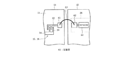
第2実施形態によるジャイロセンサユニットの要部を図4に示す。
第2実施形態では、図4に示すように調整電圧印加部26の構成が第1実施形態と異なる。調整電圧印加部26は、記憶部61を有している。記憶部61は、例えば回路基板12に形成されたEPROMなどを有している。記憶部61は、調整用固定電極42に印加する調整用の電圧を複数記憶している。記憶部61は、調整用の電圧を二つ以上記憶していることが望ましい。処理部21は、記憶部61に記憶している複数の調整用の電圧からジャイロセンサ13とジャイロセンサ14との間に所定の駆動周波数の差が生じる電圧を選択し、パッド62に印加する。パッド62は、電気配線部としてのボンディングワイヤ63によって柱部45と電気的に接続している。これにより、調整用固定電極42は、ボンディングワイヤ63を経由してパッド62と電気的に接続されている。処理部21は、選択した調整用の電圧をパッド62からボンディングワイヤ63を経由して調整用固定電極42に印加する。
第2実施形態では、記憶部に記憶した調整用の電圧に基づいて調整用固定電極42に印加する電圧を変化させている。したがって、簡単な構造でジャイロセンサ13の駆動周波数を変更することができる。
(Second Embodiment)
The principal part of the gyro sensor unit according to the second embodiment is shown in FIG.
In the second embodiment, as shown in FIG. 4, the configuration of the adjustment
In the second embodiment, the voltage applied to the adjustment fixed
(その他の実施形態)
以上説明した複数の実施形態では、駆動梁35を挟んで振動子本体31と一体の検出部34に調整用可動電極39を設け、振動子本体31の振動方向と同一方向に静電力を加える例について説明した。しかし、調整用可動電極39は、検出部34に限らず振動子本体31に設けてもよい。また、静電力を加える方向は、振動子本体31の振動方向と同一方向に限らず、検出方向と同一であってもよく、振動子15、16の振動を制限または促進可能であれば任意に方向に静電力を加える構成とすることができる。また、複数の実施形態では、ジャイロセンサ13、14がそれぞれ二つの振動子を有する例について説明した。しかし、各ジャイロセンサ13、14に設けられる振動子は、二つに限らず、一つまたは三つ以上であってもよい。さらに、ジャイロセンサユニット10は、二つのジャイロセンサ13、14に限らず、二つ以上の振動子を有する三つ以上のジャイロセンサを備えていてもよい。
(Other embodiments)
In the embodiments described above, the adjustment
ところで、ジャイロセンサ13、14は、個体差によって振動子15、16、17、18の駆動周波数が設計範囲を超える場合がある。すなわち、駆動用固定電極33に印加する電圧および周波数が所定値であっても、各振動子15、16、17、18の駆動周波数が過大あるいは過小になる場合がある。このような場合に対処するために、ジャイロセンサ13およびジャイロセンサ14の双方に調整用可動電極39および調整用固定電極42を設け、振動子15、16、17、18の駆動周波数が設計範囲の上限または下限を超えるとき、調整用固定電極42に電圧を印加して振動子15、16、17、18の駆動周波数を設計範囲内に収束させる構成としてもよい。
また、ジャイロセンサ13の出力信号、およびジャイロセンサ14の出力信号にそれぞれビートノイズが印加されている場合、ジャイロセンサ13の出力信号とジャイロセンサ14の出力信号同士を加算もしくは減算することで、ノイズの除去を行ってもよい。
Incidentally, in the
Further, when beat noise is applied to the output signal of the
以上説明した本発明は、上記実施形態に限定されるものではなく、その要旨を逸脱しない範囲で種々の実施形態に適用可能である。 The present invention described above is not limited to the above-described embodiment, and can be applied to various embodiments without departing from the gist thereof.
図面中、10はジャイロセンサユニット、11はセンサ基板、12は回路基板、13、14はジャイロセンサ、15、16、17、18は振動子、21は処理部(駆動周波数変更手段)、26は調整電圧印加部(駆動周波数変更手段)、39は調整用可動電極(振動子電極)、51、52、62はパッド(駆動周波数変更手段)、53、63はボンディングワイヤ(駆動周波数変更手段、電気配線部)、61は記憶部(駆動周波数変更手段)を示す。
In the drawing, 10 is a gyro sensor unit, 11 is a sensor board, 12 is a circuit board, 13 and 14 are gyro sensors, 15, 16, 17 and 18 are vibrators, 21 is a processing unit (drive frequency changing means), and 26 is Adjustment voltage application unit (driving frequency changing means), 39 is a movable electrode for adjustment (vibrator electrode), 51, 52 and 62 are pads (driving frequency changing means), and 53 and 63 are bonding wires (driving frequency changing means,
Claims (5)
前記ジャイロセンサが複数設けられているセンサ基板と、
前記複数のジャイロセンサに印加する駆動電圧を調整する回路基板と、
前記複数のジャイロセンサの共振周波数を調整するために、前記複数のジャイロセンサのうち少なくとも一方の駆動周波数を電気的に変更する駆動周波数変更手段と、
を備えることを特徴とするジャイロセンサユニット。 A gyro sensor having a vibrator;
A sensor substrate provided with a plurality of the gyro sensors;
A circuit board for adjusting a drive voltage applied to the plurality of gyro sensors;
Drive frequency changing means for electrically changing the drive frequency of at least one of the plurality of gyro sensors in order to adjust the resonance frequency of the plurality of gyro sensors;
A gyro sensor unit comprising:
前記駆動周波数変更手段は、前記回路基板に設けられ前記ジャイロセンサの駆動周波数を変更するための調整電圧が印加されている複数のパッド電極と、前記パッド電極のいずれか一つと前記振動子電極とを電気的に接続する電気配線部と、を有することを特徴とする請求項1記載のジャイロセンサユニット。 The vibrator has a vibrator electrode for adjusting a driving frequency,
The drive frequency changing means includes a plurality of pad electrodes provided on the circuit board to which an adjustment voltage for changing the drive frequency of the gyro sensor is applied, one of the pad electrodes, and the vibrator electrode. The gyro sensor unit according to claim 1, further comprising: an electric wiring portion that electrically connects the two.
前記駆動周波数変更手段は、前記回路基板に設けられ前記ジャイロセンサの駆動周波数を変更するための複数の調整電圧を記憶している記憶部と、前記記憶部に記憶された調整電圧のいずれか一つを前記振動子電極に印加する電気配線部と、を有することを特徴とする請求項1記載のジャイロセンサユニット。 The vibrator has a vibrator electrode for adjusting a driving frequency,
The drive frequency changing means is one of a storage unit that is provided on the circuit board and stores a plurality of adjustment voltages for changing the drive frequency of the gyro sensor, and an adjustment voltage stored in the storage unit. The gyro sensor unit according to claim 1, further comprising: an electric wiring portion that applies one to the vibrator electrode.
Priority Applications (1)
| Application Number | Priority Date | Filing Date | Title |
|---|---|---|---|
| JP2008023850A JP2009186213A (en) | 2008-02-04 | 2008-02-04 | Gyro sensor unit |
Applications Claiming Priority (1)
| Application Number | Priority Date | Filing Date | Title |
|---|---|---|---|
| JP2008023850A JP2009186213A (en) | 2008-02-04 | 2008-02-04 | Gyro sensor unit |
Publications (1)
| Publication Number | Publication Date |
|---|---|
| JP2009186213A true JP2009186213A (en) | 2009-08-20 |
Family
ID=41069614
Family Applications (1)
| Application Number | Title | Priority Date | Filing Date |
|---|---|---|---|
| JP2008023850A Pending JP2009186213A (en) | 2008-02-04 | 2008-02-04 | Gyro sensor unit |
Country Status (1)
| Country | Link |
|---|---|
| JP (1) | JP2009186213A (en) |
Cited By (26)
| Publication number | Priority date | Publication date | Assignee | Title |
|---|---|---|---|---|
| CN102944230A (en) * | 2012-11-14 | 2013-02-27 | 浙江大学 | Constant-frequency drive method and constant-frequency drive device of tunable micromechanical gyroscope |
| CN103162681A (en) * | 2013-03-19 | 2013-06-19 | 中国人民解放军国防科学技术大学 | Method and device for testing signals used for micromechanical gyroscope |
| CN103210278A (en) * | 2010-09-20 | 2013-07-17 | 快捷半导体公司 | Inertial sensor mode tuning circuit |
| US8739626B2 (en) | 2009-08-04 | 2014-06-03 | Fairchild Semiconductor Corporation | Micromachined inertial sensor devices |
| US8813564B2 (en) | 2010-09-18 | 2014-08-26 | Fairchild Semiconductor Corporation | MEMS multi-axis gyroscope with central suspension and gimbal structure |
| US8978475B2 (en) | 2012-02-01 | 2015-03-17 | Fairchild Semiconductor Corporation | MEMS proof mass with split z-axis portions |
| US9006846B2 (en) | 2010-09-20 | 2015-04-14 | Fairchild Semiconductor Corporation | Through silicon via with reduced shunt capacitance |
| US9062972B2 (en) | 2012-01-31 | 2015-06-23 | Fairchild Semiconductor Corporation | MEMS multi-axis accelerometer electrode structure |
| US9069006B2 (en) | 2012-04-05 | 2015-06-30 | Fairchild Semiconductor Corporation | Self test of MEMS gyroscope with ASICs integrated capacitors |
| US9094027B2 (en) | 2012-04-12 | 2015-07-28 | Fairchild Semiconductor Corporation | Micro-electro-mechanical-system (MEMS) driver |
| US9095072B2 (en) | 2010-09-18 | 2015-07-28 | Fairchild Semiconductor Corporation | Multi-die MEMS package |
| US9156673B2 (en) | 2010-09-18 | 2015-10-13 | Fairchild Semiconductor Corporation | Packaging to reduce stress on microelectromechanical systems |
| US9246018B2 (en) | 2010-09-18 | 2016-01-26 | Fairchild Semiconductor Corporation | Micromachined monolithic 3-axis gyroscope with single drive |
| US9278846B2 (en) | 2010-09-18 | 2016-03-08 | Fairchild Semiconductor Corporation | Micromachined monolithic 6-axis inertial sensor |
| US9352961B2 (en) | 2010-09-18 | 2016-05-31 | Fairchild Semiconductor Corporation | Flexure bearing to reduce quadrature for resonating micromachined devices |
| US9425328B2 (en) | 2012-09-12 | 2016-08-23 | Fairchild Semiconductor Corporation | Through silicon via including multi-material fill |
| US9444404B2 (en) | 2012-04-05 | 2016-09-13 | Fairchild Semiconductor Corporation | MEMS device front-end charge amplifier |
| US9488693B2 (en) | 2012-04-04 | 2016-11-08 | Fairchild Semiconductor Corporation | Self test of MEMS accelerometer with ASICS integrated capacitors |
| US9618361B2 (en) | 2012-04-05 | 2017-04-11 | Fairchild Semiconductor Corporation | MEMS device automatic-gain control loop for mechanical amplitude drive |
| US9625272B2 (en) | 2012-04-12 | 2017-04-18 | Fairchild Semiconductor Corporation | MEMS quadrature cancellation and signal demodulation |
| US10060757B2 (en) | 2012-04-05 | 2018-08-28 | Fairchild Semiconductor Corporation | MEMS device quadrature shift cancellation |
| US10065851B2 (en) | 2010-09-20 | 2018-09-04 | Fairchild Semiconductor Corporation | Microelectromechanical pressure sensor including reference capacitor |
| WO2019073647A1 (en) | 2017-10-12 | 2019-04-18 | ソニー株式会社 | Information processing device, information processing method, and program |
| EP2858794B1 (en) | 2012-06-08 | 2021-04-14 | iRobot Corporation | Carpet drift estimation and compensation using two sets of sensors |
| WO2021131780A1 (en) * | 2019-12-26 | 2021-07-01 | ソニーグループ株式会社 | Drive control device, drive control method, and program |
| WO2022004375A1 (en) * | 2020-06-30 | 2022-01-06 | ソニーグループ株式会社 | Drive control device and drive control method |
Citations (12)
| Publication number | Priority date | Publication date | Assignee | Title |
|---|---|---|---|---|
| JPH05118854A (en) * | 1991-10-24 | 1993-05-14 | Akai Electric Co Ltd | Vibration gyro |
| JPH07190784A (en) * | 1993-03-24 | 1995-07-28 | Toyota Motor Corp | Angular velocity detector |
| JPH07301535A (en) * | 1994-05-02 | 1995-11-14 | Murata Mfg Co Ltd | Frequency adjusting mechanism of vibrating element |
| JPH09105639A (en) * | 1995-08-08 | 1997-04-22 | Murata Mfg Co Ltd | Vibrating gyro and its manufacture |
| JPH09178494A (en) * | 1995-10-28 | 1997-07-11 | Samsung Electron Co Ltd | Vibrating structure, actuator having the vibrating structure, and control method of natural frequency of the vibrating structure |
| JPH09250929A (en) * | 1996-03-14 | 1997-09-22 | Aisin Seiki Co Ltd | Angular velocity detector |
| JPH10170276A (en) * | 1996-12-13 | 1998-06-26 | Toyota Central Res & Dev Lab Inc | Resonant angular velocity sensor |
| JPH112525A (en) * | 1997-06-11 | 1999-01-06 | Tokin Corp | Angular velocity sensor |
| JP2002515976A (en) * | 1996-05-31 | 2002-05-28 | ザ リージェンツ オブ ザ ユニヴァーシティ オブ カリフォルニア | Ultra-small precision vibration rate gyroscope |
| WO2006006597A1 (en) * | 2004-07-12 | 2006-01-19 | Sumitomo Precision Products | Angular speed sensor |
| JP2007040961A (en) * | 2005-03-04 | 2007-02-15 | Sony Corp | Vibration type gyro sensor |
| JP2007057340A (en) * | 2005-08-24 | 2007-03-08 | Citizen Watch Co Ltd | Oscillation circuit and angular velocity sensor |
-
2008
- 2008-02-04 JP JP2008023850A patent/JP2009186213A/en active Pending
Patent Citations (12)
| Publication number | Priority date | Publication date | Assignee | Title |
|---|---|---|---|---|
| JPH05118854A (en) * | 1991-10-24 | 1993-05-14 | Akai Electric Co Ltd | Vibration gyro |
| JPH07190784A (en) * | 1993-03-24 | 1995-07-28 | Toyota Motor Corp | Angular velocity detector |
| JPH07301535A (en) * | 1994-05-02 | 1995-11-14 | Murata Mfg Co Ltd | Frequency adjusting mechanism of vibrating element |
| JPH09105639A (en) * | 1995-08-08 | 1997-04-22 | Murata Mfg Co Ltd | Vibrating gyro and its manufacture |
| JPH09178494A (en) * | 1995-10-28 | 1997-07-11 | Samsung Electron Co Ltd | Vibrating structure, actuator having the vibrating structure, and control method of natural frequency of the vibrating structure |
| JPH09250929A (en) * | 1996-03-14 | 1997-09-22 | Aisin Seiki Co Ltd | Angular velocity detector |
| JP2002515976A (en) * | 1996-05-31 | 2002-05-28 | ザ リージェンツ オブ ザ ユニヴァーシティ オブ カリフォルニア | Ultra-small precision vibration rate gyroscope |
| JPH10170276A (en) * | 1996-12-13 | 1998-06-26 | Toyota Central Res & Dev Lab Inc | Resonant angular velocity sensor |
| JPH112525A (en) * | 1997-06-11 | 1999-01-06 | Tokin Corp | Angular velocity sensor |
| WO2006006597A1 (en) * | 2004-07-12 | 2006-01-19 | Sumitomo Precision Products | Angular speed sensor |
| JP2007040961A (en) * | 2005-03-04 | 2007-02-15 | Sony Corp | Vibration type gyro sensor |
| JP2007057340A (en) * | 2005-08-24 | 2007-03-08 | Citizen Watch Co Ltd | Oscillation circuit and angular velocity sensor |
Cited By (36)
| Publication number | Priority date | Publication date | Assignee | Title |
|---|---|---|---|---|
| US8739626B2 (en) | 2009-08-04 | 2014-06-03 | Fairchild Semiconductor Corporation | Micromachined inertial sensor devices |
| US10050155B2 (en) | 2010-09-18 | 2018-08-14 | Fairchild Semiconductor Corporation | Micromachined monolithic 3-axis gyroscope with single drive |
| US9246018B2 (en) | 2010-09-18 | 2016-01-26 | Fairchild Semiconductor Corporation | Micromachined monolithic 3-axis gyroscope with single drive |
| US9352961B2 (en) | 2010-09-18 | 2016-05-31 | Fairchild Semiconductor Corporation | Flexure bearing to reduce quadrature for resonating micromachined devices |
| US8813564B2 (en) | 2010-09-18 | 2014-08-26 | Fairchild Semiconductor Corporation | MEMS multi-axis gyroscope with central suspension and gimbal structure |
| US9278845B2 (en) | 2010-09-18 | 2016-03-08 | Fairchild Semiconductor Corporation | MEMS multi-axis gyroscope Z-axis electrode structure |
| US9278846B2 (en) | 2010-09-18 | 2016-03-08 | Fairchild Semiconductor Corporation | Micromachined monolithic 6-axis inertial sensor |
| US9856132B2 (en) | 2010-09-18 | 2018-01-02 | Fairchild Semiconductor Corporation | Sealed packaging for microelectromechanical systems |
| US9455354B2 (en) | 2010-09-18 | 2016-09-27 | Fairchild Semiconductor Corporation | Micromachined 3-axis accelerometer with a single proof-mass |
| US9156673B2 (en) | 2010-09-18 | 2015-10-13 | Fairchild Semiconductor Corporation | Packaging to reduce stress on microelectromechanical systems |
| US9095072B2 (en) | 2010-09-18 | 2015-07-28 | Fairchild Semiconductor Corporation | Multi-die MEMS package |
| CN103210278B (en) * | 2010-09-20 | 2015-09-09 | 快捷半导体公司 | pattern matching circuit, method and system |
| CN103210278A (en) * | 2010-09-20 | 2013-07-17 | 快捷半导体公司 | Inertial sensor mode tuning circuit |
| US9006846B2 (en) | 2010-09-20 | 2015-04-14 | Fairchild Semiconductor Corporation | Through silicon via with reduced shunt capacitance |
| US10065851B2 (en) | 2010-09-20 | 2018-09-04 | Fairchild Semiconductor Corporation | Microelectromechanical pressure sensor including reference capacitor |
| US9062972B2 (en) | 2012-01-31 | 2015-06-23 | Fairchild Semiconductor Corporation | MEMS multi-axis accelerometer electrode structure |
| US9599472B2 (en) | 2012-02-01 | 2017-03-21 | Fairchild Semiconductor Corporation | MEMS proof mass with split Z-axis portions |
| US8978475B2 (en) | 2012-02-01 | 2015-03-17 | Fairchild Semiconductor Corporation | MEMS proof mass with split z-axis portions |
| US9488693B2 (en) | 2012-04-04 | 2016-11-08 | Fairchild Semiconductor Corporation | Self test of MEMS accelerometer with ASICS integrated capacitors |
| US9069006B2 (en) | 2012-04-05 | 2015-06-30 | Fairchild Semiconductor Corporation | Self test of MEMS gyroscope with ASICs integrated capacitors |
| US9618361B2 (en) | 2012-04-05 | 2017-04-11 | Fairchild Semiconductor Corporation | MEMS device automatic-gain control loop for mechanical amplitude drive |
| US10060757B2 (en) | 2012-04-05 | 2018-08-28 | Fairchild Semiconductor Corporation | MEMS device quadrature shift cancellation |
| US9444404B2 (en) | 2012-04-05 | 2016-09-13 | Fairchild Semiconductor Corporation | MEMS device front-end charge amplifier |
| US9625272B2 (en) | 2012-04-12 | 2017-04-18 | Fairchild Semiconductor Corporation | MEMS quadrature cancellation and signal demodulation |
| US9094027B2 (en) | 2012-04-12 | 2015-07-28 | Fairchild Semiconductor Corporation | Micro-electro-mechanical-system (MEMS) driver |
| EP2858794B1 (en) | 2012-06-08 | 2021-04-14 | iRobot Corporation | Carpet drift estimation and compensation using two sets of sensors |
| US11926066B2 (en) | 2012-06-08 | 2024-03-12 | Irobot Corporation | Carpet drift estimation using differential sensors or visual measurements |
| US9802814B2 (en) | 2012-09-12 | 2017-10-31 | Fairchild Semiconductor Corporation | Through silicon via including multi-material fill |
| US9425328B2 (en) | 2012-09-12 | 2016-08-23 | Fairchild Semiconductor Corporation | Through silicon via including multi-material fill |
| CN102944230A (en) * | 2012-11-14 | 2013-02-27 | 浙江大学 | Constant-frequency drive method and constant-frequency drive device of tunable micromechanical gyroscope |
| CN103162681B (en) * | 2013-03-19 | 2015-06-24 | 中国人民解放军国防科学技术大学 | Method and device for testing signals used for micromechanical gyroscope |
| CN103162681A (en) * | 2013-03-19 | 2013-06-19 | 中国人民解放军国防科学技术大学 | Method and device for testing signals used for micromechanical gyroscope |
| WO2019073647A1 (en) | 2017-10-12 | 2019-04-18 | ソニー株式会社 | Information processing device, information processing method, and program |
| US11614461B2 (en) | 2017-10-12 | 2023-03-28 | Sony Corporation | Information processing device and information processing method |
| WO2021131780A1 (en) * | 2019-12-26 | 2021-07-01 | ソニーグループ株式会社 | Drive control device, drive control method, and program |
| WO2022004375A1 (en) * | 2020-06-30 | 2022-01-06 | ソニーグループ株式会社 | Drive control device and drive control method |
Similar Documents
| Publication | Publication Date | Title |
|---|---|---|
| JP2009186213A (en) | Gyro sensor unit | |
| US9835641B2 (en) | Angular velocity detection device and angular velocity sensor including the same | |
| JP4874067B2 (en) | Angular velocity sensor | |
| KR20120042861A (en) | Angular velocity sensor, and synchronous detection circuit used therein | |
| JP6031682B2 (en) | Angular velocity sensor and detection element used therefor | |
| JP2010054431A (en) | External force detecting apparatus and method of correcting output signal | |
| JP4915474B2 (en) | External force detection device and wiring breakage detection method | |
| JP4556515B2 (en) | Angular velocity sensor | |
| USRE46514E1 (en) | Angular velocity sensor element, angular velocity sensor and angular velocity sensor unit both using angular velocity sensor element, and signal detecting method for angular velocity sensor unit | |
| JP3603746B2 (en) | Vibrator | |
| US20190310086A1 (en) | Gyrosensor, signal processing device, electronic apparatus, and method of controlling a gyrosensor | |
| JP4600031B2 (en) | Angular velocity detector | |
| JP5407259B2 (en) | Angular velocity sensor element | |
| JP7045620B2 (en) | Control method of angular velocity sensor and angular velocity sensor | |
| JP2006010408A (en) | Vibratory gyro | |
| JP2010190705A (en) | Three-axis detecting angular velocity sensor | |
| JP5964036B2 (en) | Angular velocity detector | |
| JP2005091287A (en) | Angular velocity detection device | |
| JP2007178299A (en) | Angular velocity sensor | |
| JP2018080958A (en) | Gyro sensor and electronic device | |
| JP6702053B2 (en) | Gyro sensor and electronic equipment | |
| JP2016095176A (en) | Angular velocity sensor and electronic device using the angular velocity sensor | |
| JP2015166748A (en) | Angular velocity sensor element and angular velocity sensor | |
| JP5849243B2 (en) | Angular velocity sensor element | |
| JP5786141B2 (en) | Angular velocity sensor element |
Legal Events
| Date | Code | Title | Description |
|---|---|---|---|
| A621 | Written request for application examination |
Free format text: JAPANESE INTERMEDIATE CODE: A621 Effective date: 20090629 |
|
| A977 | Report on retrieval |
Free format text: JAPANESE INTERMEDIATE CODE: A971007 Effective date: 20111117 |
|
| A131 | Notification of reasons for refusal |
Free format text: JAPANESE INTERMEDIATE CODE: A131 Effective date: 20111122 |
|
| A02 | Decision of refusal |
Free format text: JAPANESE INTERMEDIATE CODE: A02 Effective date: 20120515 |