[go: up one dir, main page]

JP2009174753A - Heat exchanger and heat pump water heater - Google Patents

Heat exchanger and heat pump water heater Download PDF

Info

Publication number
JP2009174753A
JP2009174753A JP2008012564A JP2008012564A JP2009174753A JP 2009174753 A JP2009174753 A JP 2009174753A JP 2008012564 A JP2008012564 A JP 2008012564A JP 2008012564 A JP2008012564 A JP 2008012564A JP 2009174753 A JP2009174753 A JP 2009174753A
Authority
JP
Japan
Prior art keywords
flow path
heat
hot water
heat exchanger
heat medium
Prior art date
Legal status (The legal status is an assumption and is not a legal conclusion. Google has not performed a legal analysis and makes no representation as to the accuracy of the status listed.)
Pending
Application number
JP2008012564A
Other languages
Japanese (ja)
Inventor
Tetsu Nanatane
哲ニ 七種
So Nomoto
宗 野本
Hitoshi Iijima
等 飯嶋
Current Assignee (The listed assignees may be inaccurate. Google has not performed a legal analysis and makes no representation or warranty as to the accuracy of the list.)
Mitsubishi Electric Corp
Original Assignee
Mitsubishi Electric Corp
Priority date (The priority date is an assumption and is not a legal conclusion. Google has not performed a legal analysis and makes no representation as to the accuracy of the date listed.)
Filing date
Publication date
Application filed by Mitsubishi Electric Corp filed Critical Mitsubishi Electric Corp
Priority to JP2008012564A priority Critical patent/JP2009174753A/en
Publication of JP2009174753A publication Critical patent/JP2009174753A/en
Pending legal-status Critical Current

Links

Images

Landscapes

  • Heat-Pump Type And Storage Water Heaters (AREA)
  • Details Of Fluid Heaters (AREA)
  • Heat-Exchange Devices With Radiators And Conduit Assemblies (AREA)

Abstract

<P>PROBLEM TO BE SOLVED: To provide an integrated compact heat exchanger low in radiation loss as a heat exchanger exchanging heat among three or more circuits in which heat mediums are circulated, and to provide a heat pump water heater using the heat exchanger. <P>SOLUTION: This heat exchanger comprises a first flow channel 22 for circulating the first heat medium, a second flow channel 23 disposed near the first flow channel 22 for circulating the second heat medium, a third flow channel 24 disposed near the first flow channel 22 or the second flow channel 23 for circulating the third heat medium, and a heat conductive resin 25 integrally surrounding the first flow channel 22, the second flow channel 23 and the third flow channel 24, and heat can be exchanged between the first heat medium and the second heat medium between the first heat medium and the third heat medium, and between the second heat medium and the third heat medium. <P>COPYRIGHT: (C)2009,JPO&INPIT

Description

本発明は、熱交換器及びヒートポンプ給湯機に関し、特に例えば3以上の熱媒体間で熱交換する熱交換器、及び熱媒体を循環する回路を3系統以上有するヒートポンプ給湯機に関するものである。   The present invention relates to a heat exchanger and a heat pump water heater, and more particularly to a heat exchanger that exchanges heat between, for example, three or more heat media, and a heat pump water heater that has three or more circuits that circulate the heat media.

第1流体と第2流体とを熱交換すると共に第1流体と第3流体とも熱交換する従来の熱交換器であって、第1流体が流通する扁平な第1チューブの片面に第2流体が流通する第2チューブを接合し、第1チューブのもう一方の片面に前記第3流体が流通する第3チューブを接合した熱交換器がある(例えば、特許文献1参照。)。
また、貯湯タンクを有する貯湯式給湯装置の熱交換器ユニットとしては、加熱側である一次側が1回路で形成され、加熱される二次側が少なくとも2回路で構成され、一次側の冷媒管と二次側の給湯用水管及び浴槽加熱用水管を、同一のコイル状形状に巻き、一次側と二次側とが交互に配置されるよう構成したものがある(例えば、特許文献2参照。)。
A conventional heat exchanger that exchanges heat between the first fluid and the second fluid and also exchanges heat between the first fluid and the third fluid, and the second fluid is provided on one side of a flat first tube through which the first fluid flows. There is a heat exchanger in which a second tube through which the third fluid flows is joined and a third tube through which the third fluid flows is joined to the other side of the first tube (see, for example, Patent Document 1).
Further, as a heat exchanger unit of a hot water storage type hot water supply apparatus having a hot water storage tank, the primary side which is the heating side is formed by one circuit, the secondary side to be heated is constituted by at least two circuits, and the primary side refrigerant pipe and There is a configuration in which the water pipe for hot water supply on the secondary side and the water pipe for heating the bathtub are wound in the same coil shape so that the primary side and the secondary side are alternately arranged (for example, see Patent Document 2).

特開2003−28582号公報(第4頁、図2)JP 2003-28582 A (page 4, FIG. 2) 特開2005−315553号公報(第9頁〜第12頁、図3)JP 2005-315553 A (page 9 to page 12, FIG. 3)

しかしながら、特許文献1に掲載された従来の構成の熱交換器は、第1流体と第2流体とを熱交換すると共に第1流体と第3流体とも熱交換するものであるが、第2流体と第3流体とは熱交換する構成ではなかった。例えば第1流体を冷媒、第2流体を水、第3流体をブラインとした実施の形態1が記載されている。この場合には冷媒と水を熱交換できると共に冷媒とブラインを熱交換できる構成である。ところが、水とブラインを熱交換できる構成ではなかった。また、実施の形態2では、冷媒と水、水とブラインを熱交換できる構成ではあるが、冷媒とブラインを熱交換できる構成ではなかった。   However, the heat exchanger having the conventional configuration disclosed in Patent Document 1 exchanges heat between the first fluid and the second fluid and also exchanges heat between the first fluid and the third fluid. The third fluid was not configured to exchange heat. For example, Embodiment 1 in which the first fluid is a refrigerant, the second fluid is water, and the third fluid is brine is described. In this case, heat can be exchanged between the refrigerant and water, and heat can be exchanged between the refrigerant and brine. However, it was not the structure which can heat-exchange water and brine. In the second embodiment, the refrigerant and water and the water and brine can be heat-exchanged, but the refrigerant and brine cannot be heat-exchanged.

また、特許文献2に掲載された従来の構成の熱交換器も、二次側チューブである追焚き用熱交換器と暖房用熱交換器間では熱交換しない構成であった。さらに、冷媒管と水管がともに円管であり、冷媒管と水管の接触部は十分な伝熱面積が取れない。このため、必要な熱交換量を確保するために配管長を長くしなければならず、熱交換器が大型化し、重量も増加するという問題がある。またコイル形状に巻いているため、周囲空気に接触する面積も大きく、放熱ロス低減のために熱交換器周囲に覆う広い面積の断熱材が必要となり、熱交換器の材料費や加工費が増加するという問題もある。   Moreover, the heat exchanger of the conventional structure published in patent document 2 was also a structure which does not heat-exchange between the heat exchanger for reheating which is a secondary side tube, and the heat exchanger for heating. Furthermore, both the refrigerant pipe and the water pipe are circular pipes, and a contact portion between the refrigerant pipe and the water pipe cannot take a sufficient heat transfer area. For this reason, in order to ensure the necessary heat exchange amount, the length of the pipe has to be increased, and there is a problem that the heat exchanger is increased in size and weight. In addition, because it is wound in a coil shape, the area that comes into contact with the surrounding air is large, and in order to reduce heat dissipation loss, a large area of heat insulating material that covers the heat exchanger is required, which increases the material cost and processing cost of the heat exchanger. There is also the problem of doing.

本発明は上述のような課題を解消するためになされたものであり、3以上の熱媒体間で熱交換する熱交換器で、第1の熱媒体と第2の熱媒体とを熱交換する構成で、かつ第1の熱媒体と第3の熱媒体とを熱交換する構成で、さらに、第2の熱媒体と第3の熱媒体とを熱交換する構成の熱交換器であって、コンパクトで放熱ロスが小さい熱交換器を得ることを目的とする。
また、この熱交換器を用いたヒートポンプ給湯機を得ることを目的とする。
The present invention has been made to solve the above-described problems, and is a heat exchanger for exchanging heat between three or more heat media, and exchanging heat between the first heat media and the second heat media. A heat exchanger configured to exchange heat between the first heat medium and the third heat medium, and further configured to exchange heat between the second heat medium and the third heat medium, The purpose is to obtain a compact heat exchanger with low heat dissipation loss.
Moreover, it aims at obtaining the heat pump water heater using this heat exchanger.

本発明に係る熱交換器は、第1の熱媒体が流通する第1流路と、前記第1流路に近接して設けられ、第2の熱媒体が流通する第2流路と、前記第1流路又は前記第2流路に近接して設けられ、第3の熱媒体が流通する第3流路と、熱伝導性を有し、前記第1流路及び前記第2流路及び前記第3流路を包囲して一体化する熱伝導性樹脂と、を備え、前記第1流路を流れる第1の熱媒体と前記第2流路を流れる第2の熱媒体とを熱交換可能とし、前記第1流路を流れる第1の熱媒体と前記第3流路を流れる第3の熱媒体とを熱交換可能とし、さらに前記第2流路を流れる第2の熱媒体と前記第3流路を流れる第3の熱媒体とを熱交換可能とすることを特徴とするものである。   The heat exchanger according to the present invention includes a first flow path through which a first heat medium flows, a second flow path that is provided close to the first flow path and through which a second heat medium flows, A third flow path that is provided close to the first flow path or the second flow path and through which the third heat medium flows; and has thermal conductivity; the first flow path and the second flow path; A heat conductive resin that surrounds and integrates the third flow path, and exchanges heat between the first heat medium flowing through the first flow path and the second heat medium flowing through the second flow path. Enabling heat exchange between the first heat medium flowing through the first flow path and the third heat medium flowing through the third flow path, and the second heat medium flowing through the second flow path and the Heat exchange is possible with the third heat medium flowing through the third flow path.

また、本発明に係るヒートポンプ給湯機は、圧縮機、放熱器として動作する熱交換器、膨張弁、及び蒸発器を環状に接続して冷媒を循環させる冷凍サイクルと、給湯タンク、前記熱交換器、及び給湯ポンプを環状に接続して水を循環させる給湯水回路と、前記熱交換器及び循環ポンプを環状に接続して熱媒体を循環させる温熱利用回路と、を備え、前記熱交換器は上記に記載の熱交換器であり、前記熱交換器の前記第1流路に前記冷凍サイクルの前記圧縮機を吐出した高温の冷媒を流通させ、前記第2流路及び前記第3流路のいずれか一方の流路に前記給湯水回路を循環する水を流通させ、他方の流路に前記温熱利用回路を循環する熱媒体を流通させることを特徴とするものである。   The heat pump water heater according to the present invention includes a compressor, a heat exchanger that operates as a radiator, an expansion valve, a refrigeration cycle that circulates a refrigerant by connecting an evaporator in an annular manner, a hot water tank, and the heat exchanger And a hot water supply circuit that circulates water by connecting a hot water pump in an annular shape, and a heat utilization circuit that circulates a heat medium by connecting the heat exchanger and the circulation pump in an annular shape, the heat exchanger comprising: The heat exchanger according to the above, wherein the high-temperature refrigerant discharged from the compressor of the refrigeration cycle is circulated through the first flow path of the heat exchanger, and the second flow path and the third flow path are The water circulating in the hot water supply circuit is circulated through one of the flow paths, and the heat medium circulating through the thermal utilization circuit is circulated through the other flow path.

本発明における熱交換器は、第1流路及び第2流路及び第3流路を包囲するように熱伝導性樹脂を設けて熱交換器の複数の流路を一体化しているため、第1流路を流れる第1の熱媒体と第2流路を流れる第2の熱媒体を熱交換でき、第2流路を流れる第2の熱媒体と第3流路を流れる第3の熱媒体を熱交換でき、さらに第1流路を流れる第1の熱媒体と第3流路を流れる第3の熱媒体を、熱伝導性樹脂を介して熱交換できる。また、一体化することでコンパクトな構成で、熱交換器外表面積も小さくでき周囲空気への放熱ロスを小さくすることができる。
また、この熱交換器を用いたヒートポンプ給湯機は、コンパクトに構成でき、冷凍サイクルによる熱源と給湯タンク内の温熱による熱源を選択して温熱利用回路で有効に利用できる。
In the heat exchanger according to the present invention, the heat conductive resin is provided so as to surround the first flow path, the second flow path, and the third flow path, and the plurality of flow paths of the heat exchanger are integrated. The first heat medium flowing through the first flow path and the second heat medium flowing through the second flow path can exchange heat, and the second heat medium flowing through the second flow path and the third heat medium flowing through the third flow path In addition, the first heat medium flowing in the first flow path and the third heat medium flowing in the third flow path can be heat-exchanged via the heat conductive resin. Moreover, by integrating, it is possible to reduce the external surface area of the heat exchanger with a compact configuration, and to reduce heat dissipation loss to the surrounding air.
In addition, a heat pump water heater using this heat exchanger can be configured compactly, and can be effectively used in a heat utilization circuit by selecting a heat source by a refrigeration cycle and a heat source by heat in a hot water tank.

実施の形態1.
図1は、本発明の実施の形態1によるヒートポンプ給湯機を示す回路構成図である。冷凍サイクル100は、圧縮機1、放熱器として動作する熱交換器である給湯追焚き一体熱交換器2、膨張弁3、及び蒸発器4を環状に接続して第1の熱媒体として冷媒を循環させる。また、給湯水回路12は、給湯タンク10、給湯追焚き一体熱交換器2、及び給湯ポンプ11を環状に接続して第2の熱媒体を循環させる。さらに、温熱利用回路として例えば追焚き回路15は、浴槽13、給湯追焚き一体熱交換器2、及び循環ポンプである追焚きポンプ14を環状に接続して、第3の熱媒体を循環させる。ここで、第1の熱媒体である冷媒としては、例えば二酸化炭素又は炭化水素又はHFC冷媒などのいずれかを循環させ、第2の熱媒体を例えば給湯タンク水、第3の熱媒体を例えば浴槽水とする。冷凍サイクル100内の蒸発器4の近傍には送風機5を有する。
Embodiment 1 FIG.
FIG. 1 is a circuit configuration diagram showing a heat pump water heater according to Embodiment 1 of the present invention. The refrigeration cycle 100 has an annular connection between the compressor 1, a hot water supply and integrated heat exchanger 2 that is a heat exchanger that operates as a radiator, an expansion valve 3, and an evaporator 4, and uses refrigerant as a first heat medium. Circulate. The hot water supply circuit 12 circulates the second heat medium by connecting the hot water supply tank 10, the hot water supply and regenerative integrated heat exchanger 2, and the hot water supply pump 11 in an annular shape. Further, for example, the reheating circuit 15 as a heat utilization circuit circulates the third heat medium by connecting the bathtub 13, the hot water reheating integrated heat exchanger 2, and the recirculation pump 14 that is a circulation pump in an annular shape. Here, as the refrigerant that is the first heat medium, for example, any one of carbon dioxide, hydrocarbon, or HFC refrigerant is circulated, the second heat medium is, for example, hot water tank water, and the third heat medium is, for example, a bathtub. Use water. A blower 5 is provided in the vicinity of the evaporator 4 in the refrigeration cycle 100.

図2は、本実施の形態の一例を示すヒートポンプ給湯機の構造を分解して示す斜視図である。なお、ここでは、給湯水回路12における給湯タンク10や給湯ポンプ11、また追焚き回路15における浴槽13や追焚きポンプ14は省略しており、冷凍サイクル100を構成する部分の熱源機のみ記載している。例えば、給湯追焚き一体熱交換器2は熱源機の底面付近に配置されており、記載を省略しているが、給湯水回路12及び追焚き回路15を介して給湯タンク10及び浴槽13と接続される。   FIG. 2 is an exploded perspective view showing the structure of a heat pump water heater showing an example of the present embodiment. Here, the hot water supply tank 10 and the hot water supply pump 11 in the hot water supply circuit 12 and the bathtub 13 and the additional pump 14 in the reheating circuit 15 are omitted, and only the heat source machine of the portion constituting the refrigeration cycle 100 is described. ing. For example, the hot water supply and regenerative integrated heat exchanger 2 is disposed near the bottom surface of the heat source machine and is not shown, but is connected to the hot water supply tank 10 and the bathtub 13 via the hot water supply circuit 12 and the reheating circuit 15. Is done.

図3は、本実施の形態に係る熱交換器として例えば給湯追焚き一体熱交換器2を示す斜視図である。ここでは図示されていないが、熱交換器2の内部では、第1流路22、第2流路23、及び第3流路24は互いに略並行に流れる流路を構成している。並行な流れとは、流れ方向が平行であることに限るものではなく、一方の流路の流れ方向が他方の流路に対して、上下左右などいずれの方向にでも0度〜45度程度傾いていてもよい。熱伝導性樹脂25によって一体化されたブロックから、例えば第1流路22を構成する扁平伝熱管21、第2流路23、第3流路24の出入口配管が出ている。さらに、冷凍サイクル100を流れる冷媒を扁平伝熱管21の複数の流路に流入及び流出させる第1分配ヘッダー26、給湯水回路12を流れる給湯タンク水を熱交換器2の例えば第2流路23に流入及び流出させる第2分配ヘッダー27、追焚き回路15を流れる浴槽水を熱交換器2の例えば第3流路24に流入及び流出させる第3分配ヘッダー28が接続されている。   FIG. 3 is a perspective view showing, for example, a hot water supply and tracking integrated heat exchanger 2 as a heat exchanger according to the present embodiment. Although not shown here, in the heat exchanger 2, the first flow path 22, the second flow path 23, and the third flow path 24 constitute flow paths that flow substantially in parallel with each other. The parallel flow is not limited to the parallel flow direction, and the flow direction of one flow path is inclined by about 0 to 45 degrees in any direction such as up, down, left, and right with respect to the other flow path. It may be. From the block integrated by the heat conductive resin 25, for example, the inlet and outlet pipes of the flat heat transfer tube 21, the second flow channel 23, and the third flow channel 24 constituting the first flow channel 22 are provided. Furthermore, the first distribution header 26 that causes the refrigerant flowing through the refrigeration cycle 100 to flow into and out of the plurality of flow paths of the flat heat transfer tubes 21, and hot water tank water that flows through the hot water supply circuit 12, for example, the second flow path 23 of the heat exchanger 2. A second distribution header 27 that flows into and out of the heat exchanger 2 and a third distribution header 28 that flows in and out of the bathtub water flowing through the tracking circuit 15 into, for example, the third flow path 24 of the heat exchanger 2 are connected.

図4は給湯追焚き一体熱交換器2の断面を詳細に示す図であり、図3のP−P線における縦断面図である。互いに略並行に流れる第1流路22、第2流路23、及び第3流路24で、第2流路23を第1流路22の流れ方向に対して略垂直な方向に近接して設け、第3流路24を第1流路22に対し第2流路23と略反対側に近接して設ける。例えば、中央部に扁平伝熱管21を配置し、給湯タンク水が流通する第2流路23を、扁平伝熱管21の向かい合う扁平な面の一方側に近接して配置する。さらに、浴槽水が流通する第3流路24を扁平伝熱管21の向かい合う扁平な面の他方側に近接して配置する。ここで、例えば冷凍サイクル100を循環する冷媒が流れる第1流路22は、並設する複数の流路を一体に構成し、外形を扁平とする扁平伝熱管21とした。扁平伝熱管21は例えばアルミニウム又はアルミニウム合金で形成する。また、第2流路23と第3流路24はそれぞれ1つの矩形状の伝熱管とし、例えば銅又はステンレスで構成する。また、熱伝導性をする熱伝導性樹脂25によって、扁平伝熱管21と第2流路23と第3流路2の例えば全体がブロック状に包囲され、一体化されている。   FIG. 4 is a diagram showing in detail the cross section of the hot water supply and tracking integrated heat exchanger 2, and is a vertical cross sectional view taken along the line PP in FIG. The first flow path 22, the second flow path 23, and the third flow path 24 that flow substantially in parallel with each other, the second flow path 23 is brought close to the direction substantially perpendicular to the flow direction of the first flow path 22. The third flow path 24 is provided close to the first flow path 22 on the substantially opposite side of the second flow path 23. For example, the flat heat transfer tube 21 is arranged at the center, and the second flow path 23 through which the hot water tank water flows is arranged close to one side of the flat surface where the flat heat transfer tube 21 faces. Furthermore, the 3rd flow path 24 through which bathtub water distribute | circulates is arrange | positioned adjacent to the other side of the flat surface where the flat heat exchanger tube 21 opposes. Here, for example, the first flow path 22 through which the refrigerant circulating in the refrigeration cycle 100 flows is formed as a flat heat transfer tube 21 in which a plurality of parallel flow paths are integrally formed and the outer shape is flat. The flat heat transfer tube 21 is made of, for example, aluminum or an aluminum alloy. Moreover, the 2nd flow path 23 and the 3rd flow path 24 are each made into one rectangular heat exchanger tube, for example, are comprised with copper or stainless steel. Further, for example, the entire flat heat transfer tube 21, the second flow path 23, and the third flow path 2 are enclosed in a block shape and integrated by a heat conductive resin 25 that performs heat conductivity.

このような構成の熱交換器2では、第1流路22を流通する冷媒と第2流路23を流通する給湯タンク水とは、流路を構成する伝熱管とその間に介在する熱伝導性樹脂25とを介して熱交換可能である。また、第1流路22を流通する冷媒と第3流路24を流通する浴槽水とは、流路を構成する伝熱管とその間に介在する熱伝導性樹脂25とを介して熱交換可能である。さら第2流路23を流通する給湯タンク水と第3流路24を流通する浴槽水も、両者間の距離は前記の流路間よりも離れているが、流路を構成する伝熱管とその間に介在する熱伝導性樹脂25とを介して熱交換可能である。
ここで、第3流路24を第1流路22に対し第2流路23と垂直方向で正反対側に近接して設けたが、これに限るものではない。第2流路23と第3流路24は第1流路22に対してある程度反対側であればよい。例えば、図4において、扁平伝熱管21の下側で図に向かって右側に偏った位置に第2流路23を設け、扁平伝熱管21の上側で図に向かって左側に偏った位置に第3流路24を設けてもよい。
In the heat exchanger 2 having such a configuration, the refrigerant flowing through the first flow path 22 and the hot water tank water flowing through the second flow path 23 are composed of the heat transfer tubes forming the flow paths and the thermal conductivity interposed therebetween. Heat exchange is possible through the resin 25. In addition, the refrigerant flowing through the first flow path 22 and the bathtub water flowing through the third flow path 24 can exchange heat via the heat transfer tubes constituting the flow path and the heat conductive resin 25 interposed therebetween. is there. Furthermore, the hot water tank water flowing through the second flow path 23 and the bathtub water flowing through the third flow path 24 are also separated from each other by a distance between the heat transfer tubes constituting the flow path. Heat exchange is possible through the heat conductive resin 25 interposed therebetween.
Here, the third flow path 24 is provided adjacent to the first flow path 22 in the direction perpendicular to the second flow path 23 in the perpendicular direction, but is not limited thereto. The second flow path 23 and the third flow path 24 may be on the opposite side to the first flow path 22 to some extent. For example, in FIG. 4, the second flow path 23 is provided at a position biased to the right side in the drawing at the lower side of the flat heat transfer tube 21, and the second flow path 23 is placed at a position biased to the left side in the drawing at the upper side of the flat heat transfer tube 21. Three flow paths 24 may be provided.

熱伝導性樹脂25は、例えば樹脂と熱伝導が良い金属粉の混合物、又は樹脂と炭素の混合物により構成される。樹脂としては、例えばエポキシ系樹脂があるが、他の樹脂でもよい。また、熱伝導が良い金属粉としては、例えばアルミニウム、銅、銀などがある。熱伝導性樹脂25の熱伝導率は10W/mK以上であることが望ましい。通常の樹脂の場合の熱伝導率は、例えば1W/mK程度であり、銅の熱伝導率は386W/mK、アルミニウムの熱伝導率は228W/mK、ステンレスの熱伝導率は16.3W/mKであるが、本実施の形態では、これらを参考にして、略10W/mK以上の熱伝導率を有する熱伝導性樹脂を用いる。即ち、樹脂に混合する金属の種類は何でもよいが、通常の樹脂に比べると、約10倍以上でステンレス程度の高い伝熱性能を有する熱伝導性樹脂を用いる。   The thermally conductive resin 25 is made of, for example, a mixture of resin and metal powder having good thermal conductivity, or a mixture of resin and carbon. Examples of the resin include an epoxy resin, but other resins may be used. Examples of the metal powder having good heat conduction include aluminum, copper, and silver. The thermal conductivity of the thermal conductive resin 25 is desirably 10 W / mK or more. The thermal conductivity in the case of a normal resin is, for example, about 1 W / mK, the thermal conductivity of copper is 386 W / mK, the thermal conductivity of aluminum is 228 W / mK, and the thermal conductivity of stainless steel is 16.3 W / mK. However, in the present embodiment, referring to these, a thermally conductive resin having a thermal conductivity of approximately 10 W / mK or more is used. That is, any kind of metal may be mixed with the resin, but a heat conductive resin having a heat transfer performance of about 10 times or more and stainless steel is used as compared with a normal resin.

以下、本実施の形態におけるヒートポンプ給湯機による給湯タンク沸き上げ運転について説明する。図1に示す圧縮機1と送風機5と給湯ポンプ11を動作させ、冷凍サイクル100と給湯水回路12を運転する。冷凍サイクル100を運転することによって、圧縮機1を吐出した高温高圧の冷媒は熱交換器2に流入し放熱して低温になる。給湯追焚き一体熱交換器2から流出した高圧低温の冷媒は、膨張弁3を通過して低圧気液二相の状態に減圧される。さらに蒸発器4で外部空気から吸熱して蒸発ガス化し、圧縮機1に再び吸入される。これと同時に、給湯ポンプ11が動作するので、給湯タンク水が熱交換器2内に流入し、扁平伝熱管21内を流れる冷媒と第2流路23内を流れる給湯タンク水との間で熱交換される。その際、冷媒から給湯タンク水に放熱することで、給湯タンク水の温度が上昇して給湯タンク10に貯溜される。   Hereinafter, the hot water tank boiling operation by the heat pump water heater in the present embodiment will be described. The compressor 1, the blower 5, and the hot water supply pump 11 shown in FIG. 1 are operated, and the refrigeration cycle 100 and the hot water supply circuit 12 are operated. By operating the refrigeration cycle 100, the high-temperature and high-pressure refrigerant discharged from the compressor 1 flows into the heat exchanger 2 and dissipates heat to a low temperature. The high-pressure and low-temperature refrigerant that has flowed out of the hot-water supply / integrated heat exchanger 2 passes through the expansion valve 3 and is decompressed to a low-pressure gas-liquid two-phase state. Further, the evaporator 4 absorbs heat from outside air to be converted into evaporative gas and is sucked into the compressor 1 again. At the same time, since the hot water supply pump 11 operates, the hot water supply tank water flows into the heat exchanger 2, and heat is generated between the refrigerant flowing in the flat heat transfer tube 21 and the hot water supply tank water flowing in the second flow path 23. Exchanged. At this time, heat is dissipated from the refrigerant to the hot water tank water, so that the temperature of the hot water tank water rises and is stored in the hot water tank 10.

冷凍サイクル100で使用する冷媒が例えば二酸化炭素のように高圧側冷媒圧力が臨界圧以上であれば、冷媒は熱交換器2内で超臨界状態のまま気液相転移しないで温度低下して放熱する。また、使用する冷媒が、例えば炭化水素冷媒又はHFC冷媒のように高圧側冷媒圧力が臨界圧以下であれば、冷媒は液化しながら放熱する。   If the refrigerant used in the refrigeration cycle 100 is, for example, carbon dioxide, the high-pressure side refrigerant pressure is equal to or higher than the critical pressure, the refrigerant is cooled in the heat exchanger 2 while maintaining the supercritical state without causing a gas-liquid phase transition. To do. Moreover, if the refrigerant | coolant to be used is a high pressure side refrigerant | coolant pressure below a critical pressure, for example like a hydrocarbon refrigerant | coolant or a HFC refrigerant | coolant, a refrigerant | coolant will radiate | emit heat while liquefying.

給湯タンク沸き上げ運転を行うときには、追焚き回路15の追焚きポンプ14を停止しているので、熱交換器2内の第3流路24に浴槽水は流れない。図4に示す給湯追焚き一体熱交換器2の内部では、第1流路22を流通する高温高圧のガス冷媒の熱は、熱伝導により扁平伝熱管21を構成するアルミニウム、及び扁平伝熱管21を取り囲む熱伝導性樹脂25を介し、銅又はステンレスで構成される第2流路23に伝わり、さらに第2流路23の内部を流れる給湯水回路12の循環水に伝わる。給湯タンク10内に90℃程度の温水を貯溜する場合、冷媒は100℃程度で熱交換器2に流入し、第2流路23を流れる温水に熱を与えて、20℃程度の冷媒温度に低下して、流出する。
近年、省エネルギー化が必要とされており、この給湯タンク沸き上げ運転は電力料金の安い深夜電力時間帯を利用して運転し、温水を貯溜する。また、給湯タンク10内の温度が低下してきた場合に随時行われることもある。また、給湯タンク10内では、例えば上方から高温水が給湯に使われ、下方から水道水が補給される。
When the hot water tank heating operation is performed, since the reheating pump 14 of the reheating circuit 15 is stopped, the bath water does not flow into the third flow path 24 in the heat exchanger 2. 4, the heat of the high-temperature and high-pressure gas refrigerant flowing through the first flow path 22 is aluminum that forms the flat heat transfer tube 21 by heat conduction, and the flat heat transfer tube 21. Is transmitted to the second flow path 23 made of copper or stainless steel, and further to the circulating water of the hot water supply circuit 12 flowing inside the second flow path 23. When hot water of about 90 ° C. is stored in the hot water supply tank 10, the refrigerant flows into the heat exchanger 2 at about 100 ° C., and heat is supplied to the hot water flowing through the second flow path 23 to reach a refrigerant temperature of about 20 ° C. Decrease and spill.
In recent years, energy saving has been required, and this hot water tank boiling operation is performed using a midnight electric power time zone where electric power charges are low, and hot water is stored. Moreover, it may be performed at any time when the temperature in the hot water supply tank 10 is lowered. Moreover, in the hot water supply tank 10, for example, high-temperature water is used for hot water supply from above, and tap water is supplied from below.

次に、本実施の形態のヒートポンプ給湯機による浴槽追焚き運転の動作について説明する。本実施の形態に係るヒートポンプ給湯機は、冷媒を熱源とする第1の浴槽追焚き方式と、給湯タンク10内の高温水を熱源とする第2の浴槽追焚き方式を有している。この2つの方式を有する給湯機は、第1、第2、第3の熱媒体のうちの2つづつの熱媒体が熱交換可能な熱交換器を用いることによって実現される。   Next, the operation of the bathtub follow-up operation by the heat pump water heater of the present embodiment will be described. The heat pump water heater according to the present embodiment has a first bathtub replenishing system using a refrigerant as a heat source and a second bathtub reheating system using high-temperature water in the hot water tank 10 as a heat source. The water heater having these two methods is realized by using a heat exchanger in which two of the first, second, and third heat media can exchange heat.

まず、冷凍サイクル100を循環する冷媒を熱源とする第1の浴槽追焚き方式の動作について説明する。圧縮機1と送風機5を動作させて冷凍サイクルを運転する。冷凍サイクル100を循環する冷媒の動作は、給湯タンク10内の水温度を上昇させる給湯タンク沸き上げ運転と同様であり、これと同時に追焚きポンプ14を動作させて追焚き回路15を運転する。追焚きポンプ14によって浴槽13内の浴槽水が循環して給湯追焚き一体熱交換器2の第3流路24を流れる。一方、圧縮機1から吐出された高温高圧の冷媒は、給湯追焚き一体熱交換器2の扁平伝熱管21を流れる。   First, the operation of the first bathtub reheating method using the refrigerant circulating in the refrigeration cycle 100 as a heat source will be described. The refrigeration cycle is operated by operating the compressor 1 and the blower 5. The operation of the refrigerant circulating in the refrigeration cycle 100 is similar to the hot water tank boiling operation for raising the water temperature in the hot water tank 10, and at the same time, the reheating pump 14 is operated to operate the reheating circuit 15. Bath water in the bathtub 13 circulates by the reheating pump 14 and flows through the third flow path 24 of the hot water supply revolving integrated heat exchanger 2. On the other hand, the high-temperature and high-pressure refrigerant discharged from the compressor 1 flows through the flat heat transfer tube 21 of the hot water supply and regenerative integrated heat exchanger 2.

なお、この運転を行うときには、給湯水回路12の給湯ポンプ11を停止しているので、熱交換器2内の第2流路23に給湯タンク水は流れない。このため、熱交換器2内では、扁平伝熱管21と第3流路24を流れる流体間で熱交換が行われる。この運転における給湯追焚き一体熱交換器2の内部では、第1流路22を流通する高温高圧のガス冷媒の熱は、熱伝導により扁平伝熱管21を構成するアルミニウム、扁平伝熱管21を取り囲む熱伝導性樹脂25を介し、銅又はステンレスで構成される第3流路24の内部を流れる浴槽水に伝わり、熱交換が行われる。冷媒から放熱された熱を追焚き回路15を循環する浴槽水に与えることで追焚き加熱を行っている。   When this operation is performed, the hot water supply pump 11 of the hot water supply circuit 12 is stopped, so that hot water tank water does not flow into the second flow path 23 in the heat exchanger 2. For this reason, in the heat exchanger 2, heat exchange is performed between the fluid flowing through the flat heat transfer tube 21 and the third flow path 24. In this operation, inside the hot water supply and integrated heat exchanger 2, the heat of the high-temperature and high-pressure gas refrigerant flowing through the first flow path 22 surrounds the aluminum constituting the flat heat transfer tube 21 and the flat heat transfer tube 21 by heat conduction. Via the heat conductive resin 25, it is transmitted to the bathtub water flowing inside the third flow path 24 made of copper or stainless steel, and heat exchange is performed. Reheating is performed by applying heat radiated from the refrigerant to the bath water circulating in the reheating circuit 15.

次に、給湯水回路12を循環する高温水を熱源とする第2の浴槽追焚き方式の動作について説明する。給湯水回路12の給湯ポンプ11と追焚き回路15の追焚きポンプ14を運転し、圧縮機1の運転は停止する。給湯ポンプ11によって給湯タンク10より吸引された高温水は、給湯追焚き一体熱交換器2の第2流路23に流入する。一方、追焚きポンプ14によって、浴槽13より吸引された浴槽水は給湯追焚き一体熱交換器2の第3流路24に流入する。この時は扁平伝熱管21に冷媒は流れない。   Next, the operation of the second bathtub reheating method using high-temperature water circulating in the hot water supply circuit 12 as a heat source will be described. The hot water supply pump 11 of the hot water supply circuit 12 and the reheating pump 14 of the reheating circuit 15 are operated, and the operation of the compressor 1 is stopped. The high temperature water sucked from the hot water supply tank 10 by the hot water supply pump 11 flows into the second flow path 23 of the hot water supply and regenerative integrated heat exchanger 2. On the other hand, the bath water sucked from the bathtub 13 by the reheating pump 14 flows into the third flow path 24 of the hot water resupplying integrated heat exchanger 2. At this time, the refrigerant does not flow through the flat heat transfer tube 21.

給湯追焚き一体熱交換器2の内部では、第2流路23を流通する給湯タンク10より流出した高温水の熱は、熱伝導により銅又はステンレスで構成される第2流路23、熱伝導性樹脂25や扁平伝熱管21のアルニミウム材を介し、銅又はステンレスで構成される第3流路24の内部を流れる浴槽水に伝わり、熱交換が行われる。   Inside the hot water supply and regenerative integrated heat exchanger 2, the heat of the high-temperature water flowing out from the hot water supply tank 10 that circulates through the second flow path 23 is the second flow path 23 made of copper or stainless steel by heat conduction, Is transferred to the bathtub water flowing through the inside of the third flow path 24 made of copper or stainless steel through the conductive resin 25 and the aluminum material of the flat heat transfer tube 21 to perform heat exchange.

この給湯追焚き一体熱交換器2においては、第1の熱媒体である高温高圧冷媒が流通する複数で構成される第1流路22を有する扁平伝熱管21と、扁平伝熱管21に近接し、第2の熱媒体である給湯タンク10内の高温水が流通する第2流路23と、扁平伝熱管21に対して第2流路23と対向し、扁平伝熱管21に近接して設けられ第3の熱媒体である浴槽13の循環温水が流通する第3流路24とが、熱伝導率が高い熱伝導性樹脂25によって一体化されているため、コンパクトで軽量な構成で給湯加熱と追焚き加熱の両方の機能を有する熱交換器を実現することができる。
また、熱交換器2の外表面積を小さくすることができるため、周囲空気への放熱ロスを低減することができる。
In this hot water supply and tracking integrated heat exchanger 2, a flat heat transfer tube 21 having a plurality of first flow passages 22 through which a high-temperature and high-pressure refrigerant that is a first heat medium circulates, and the flat heat transfer tube 21 are adjacent. The second flow path 23 through which the high-temperature water in the hot water supply tank 10, which is the second heat medium, circulates, and the flat heat transfer pipe 21 is opposed to the second flow path 23 and provided close to the flat heat transfer pipe 21. Since the third flow path 24 through which the circulating hot water of the bathtub 13 which is the third heat medium flows is integrated by the heat conductive resin 25 having a high heat conductivity, the hot water supply is heated with a compact and lightweight configuration. It is possible to realize a heat exchanger having both functions of heating and reheating.
Moreover, since the outer surface area of the heat exchanger 2 can be made small, the heat dissipation loss to ambient air can be reduced.

なお、図3及び図4で示した構成では、各流路22、23、24の全体を熱伝導性樹脂25によって包囲して一体化したが、これに限るものではない。例えば、全体を包囲していなくても、第2流路23や第3流路24を構成する伝熱管の一部が露出していてもよい。例えば図4に示した構成で、左右の端部で伝熱管の横方向長さが長い伝熱管の一部が露出するような構成でもよい。また、伝熱管の出入口付近が構成上、露出していてもよい。もちろん図3に示すように各流路22、23、24の全体を被包する構成によって熱ロスを少なくすることができる。また、熱源機に搭載する場合にもブロック化によって搭載しやすい構成となる。また、断熱材で熱交換器2の一部または全体を包めば、さらに熱ロスを少なくできる。   In the configuration shown in FIGS. 3 and 4, the entire flow paths 22, 23, and 24 are surrounded and integrated by the heat conductive resin 25, but the present invention is not limited to this. For example, a part of the heat transfer tubes constituting the second flow path 23 and the third flow path 24 may be exposed even if they do not surround the whole. For example, in the configuration shown in FIG. 4, a configuration in which a portion of the heat transfer tube having a long horizontal length at the left and right ends is exposed may be used. Further, the vicinity of the entrance / exit of the heat transfer tube may be exposed due to its configuration. Of course, as shown in FIG. 3, the heat loss can be reduced by a configuration in which the entire flow paths 22, 23, 24 are encapsulated. Moreover, when it mounts in a heat source machine, it becomes the structure which is easy to mount by block-ization. Moreover, if a part or the whole of the heat exchanger 2 is wrapped with a heat insulating material, the heat loss can be further reduced.

本実施の形態では、追焚き運転の熱源として冷凍サイクル100の高温高圧ガスと給湯タンク10内の高温水を必要に応じて選択することが可能となる。例えば、給湯タンク10内の高温水が多量に存在するときには、冷凍サイクル100を運転せずに高温水を利用して浴槽追焚き運転を行うようにすれば、節電できるヒートポンプ給湯機を構成できる。また、給湯タンク10内の高温水が少量になったときには冷凍サイクル100を利用して浴槽追焚き運転を行うようにすれば、給湯タンク10内の温水が湯切れすることなく、安定して運転できるヒートポンプ給湯機を構成できる。また、これに限ることなく、複数の運転方式を状況に応じて選択すれば、多様な運転方法を有するヒートポンプ給湯機が得られる。   In the present embodiment, the high-temperature and high-pressure gas of the refrigeration cycle 100 and the high-temperature water in the hot water supply tank 10 can be selected as necessary as the heat source for the chasing operation. For example, when there is a large amount of high-temperature water in the hot water supply tank 10, a heat pump water heater that can save electricity can be configured by performing the bathtub reheating operation using the high-temperature water without operating the refrigeration cycle 100. Further, when the hot water in the hot water supply tank 10 becomes small, if the bathtub reheating operation is performed using the refrigeration cycle 100, the hot water in the hot water supply tank 10 is operated stably without running out of hot water. Heat pump water heater can be configured. In addition, the heat pump water heater having various operation methods can be obtained by selecting a plurality of operation methods according to the situation without being limited thereto.

また、熱交換器2内の冷媒の流路を、並設する複数の流路を一体とした扁平伝熱管21としたので、冷媒が循環する伝熱管の高耐圧化を図ることができ、体積あたりの伝熱面積も大きくとることができる。また、向かい合う両面が扁平であるため、両側に他の伝熱管を配置しやすく、熱交換器2として3つの熱媒体の流路をコンパクトに構成でき、図2に示したような熱源機に搭載しやすい。   Moreover, since the flow path of the refrigerant in the heat exchanger 2 is the flat heat transfer tube 21 in which a plurality of flow paths arranged in parallel are integrated, it is possible to increase the pressure resistance of the heat transfer tube through which the refrigerant circulates. The heat transfer area per area can also be increased. In addition, since both sides facing each other are flat, it is easy to arrange other heat transfer tubes on both sides, and the heat exchanger 2 can be configured with three heat medium channels in a compact configuration, and is mounted on a heat source as shown in FIG. It's easy to do.

また、第2流路23及び第3流路24は、銅又はステンレスで構成しているため、水圧により流路の変形を抑制し熱伝導性樹脂の破壊を防止することができる。また、熱伝導樹脂で一体化する際、インサート成形が可能であり容易に製造することができる。もちろん、第2流路23と第3流路24は同じ材質でもよいが、別々の材質でもよい。少なくともステンレス程度の熱伝導率を有する材質であることが好ましい。
また、第2流路23及び第3流路24は共に1つの矩形状の伝熱管としたが、同じ形状でなくてもよい。また、複数、例えば2つ以上の複数の矩形状の伝熱管で流路を構成しても、同様の効果を奏する。第2流路23と第3流路24を複数の矩形状の伝熱管にすれば、1つの伝熱管の構成と比べて、第2流路23及び第3流路24の周囲の熱伝導性樹脂25と接触する面積が大きくなる。このため、効率よく熱交換を行うことができる。また、第1流路22を扁平伝熱管21ではなく、第2、第3流路23、24と同様の1つの矩形状の伝熱管で構成してもよい。
Moreover, since the 2nd flow path 23 and the 3rd flow path 24 are comprised with copper or stainless steel, the deformation | transformation of a flow path can be suppressed with water pressure, and destruction of a heat conductive resin can be prevented. Moreover, when integrating with a heat conductive resin, insert molding is possible and it can manufacture easily. Of course, the second flow path 23 and the third flow path 24 may be made of the same material, but may be made of different materials. A material having a thermal conductivity of at least about stainless steel is preferable.
Moreover, although the 2nd flow path 23 and the 3rd flow path 24 were made into one rectangular heat exchanger tube, it does not need to be the same shape. Further, even if the flow path is constituted by a plurality of, for example, two or more rectangular heat transfer tubes, the same effect can be obtained. If the second flow path 23 and the third flow path 24 are formed into a plurality of rectangular heat transfer tubes, the thermal conductivity around the second flow path 23 and the third flow path 24 compared to the configuration of one heat transfer tube. The area in contact with the resin 25 is increased. For this reason, heat exchange can be performed efficiently. Moreover, you may comprise the 1st flow path 22 with the one rectangular heat transfer tube similar to the 2nd, 3rd flow paths 23 and 24 instead of the flat heat transfer tube 21. FIG.

また、扁平伝熱管21を第2流路23と第3流路24の間の中央部に配設したが、これに限るものではない。例えば、第2流路23と第3流路24を近接して配設すると共に、扁平伝熱管21と第2流路23とを近接して配設してもよい。即ち、中央部に給湯タンク水が循環する第2流路23を配設し、一方側に扁平伝熱管21、他方側に第3流路24を近接して配設してもよい。浴槽水を追焚きする際、給湯タンク10内の高温水を利用することが多い場合には、この順番に流路を配置すると、効率よく熱交換ができる。
また、流路の構成は、図4に示すように下から第2流路23、扁平伝熱管21、第3流路24の順とし、第1、第2、第3の熱媒体を上記記載とは異なる流路を流通するようにしてもよい。
Moreover, although the flat heat exchanger tube 21 was arrange | positioned in the center part between the 2nd flow path 23 and the 3rd flow path 24, it does not restrict to this. For example, the second flow path 23 and the third flow path 24 may be disposed close to each other, and the flat heat transfer tube 21 and the second flow path 23 may be disposed close to each other. That is, the second flow path 23 through which the hot water tank water circulates may be disposed at the center, and the flat heat transfer tube 21 may be disposed on one side, and the third flow path 24 may be disposed on the other side. When the hot water in the hot water supply tank 10 is often used when chasing the bath water, the heat exchange can be efficiently performed by arranging the flow paths in this order.
Further, as shown in FIG. 4, the flow path is configured in the order of the second flow path 23, the flat heat transfer tube 21, and the third flow path 24 from the bottom. You may make it distribute | circulate through a different flow path.

なお、扁平伝熱管21と第2流路23の間や扁平伝熱管21と第3流路24の間には熱伝導性樹脂25が充填されているが、その距離は小さいほど伝熱抵抗(熱伝導率/距離)が小さくなるため、熱交換性能が向上する。即ち、扁平伝熱管21と第2流路23、扁平伝熱管21と第3流路24、第2流路23と第3流路24の間に存在する熱伝導性樹脂25の幅は、小さいほど熱交換性能を高めることができる。例えば、図4における扁平伝熱管21と第2流路23を接触させて両者間に熱伝導性樹脂25が介在していなくてもよい。同様に、図4における扁平伝熱管21と第3流路24を接触させて両者間に熱伝導性樹脂25が介在していなくてもよい。   In addition, although between the flat heat-transfer tube 21 and the 2nd flow path 23 and between the flat heat-transfer tube 21 and the 3rd flow path 24 is filled with the heat conductive resin 25, heat transfer resistance ( The heat exchange performance is improved because the thermal conductivity / distance is small. That is, the width of the heat conductive resin 25 existing between the flat heat transfer tube 21 and the second flow path 23, the flat heat transfer tube 21 and the third flow path 24, and the second flow path 23 and the third flow path 24 is small. The heat exchange performance can be improved as much as possible. For example, the flat heat transfer tube 21 and the second flow path 23 in FIG. 4 may be brought into contact with each other, and the heat conductive resin 25 may not be interposed therebetween. Similarly, the flat heat transfer tube 21 and the third flow path 24 in FIG. 4 may be brought into contact with each other, and the heat conductive resin 25 may not be interposed therebetween.

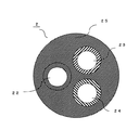
また、第2、第3流路23、24は矩形状の伝熱管で構成したが、断面が楕円状の1つ又は複数の円形状の伝熱管であっても、同様の効果を奏する。図5に他の構成例を示す。図5は熱交換器2の断面を示し、各流路22、23、24の断面を示している。例えば冷媒が流通する第1流路22と、第1流路22に近接して設けられ、例えば給湯水が流通する第2流路23と、第1流路22又は第2流路23に近接して設けられ、例えば浴槽水が流通する第3流路24と、熱伝導性を有し、第1流路22、第2流路23、及び第3流路24を包囲して一体化する熱伝導性樹脂25と、を備えた熱交換器2である。この構成の第1流路22と第2流路23と第3流路24のそれぞれは、流路に垂直な断面形状が円形状の1つの伝熱管で、構成している。   Moreover, although the 2nd, 3rd flow paths 23 and 24 were comprised by the rectangular heat exchanger tube, the same effect is show | played even if it is one or several circular heat exchanger tubes whose cross section is elliptical. FIG. 5 shows another configuration example. FIG. 5 shows a cross section of the heat exchanger 2, and shows cross sections of the flow paths 22, 23 and 24. For example, the first flow path 22 through which the refrigerant flows and the second flow path 23 through which the hot water is circulated are provided close to the first flow path 22 and the first flow path 22 or the second flow path 23. For example, the third flow path 24 through which the bath water flows and the thermal conductivity are provided, and the first flow path 22, the second flow path 23, and the third flow path 24 are surrounded and integrated. The heat exchanger 2 is provided with a heat conductive resin 25. Each of the first flow path 22, the second flow path 23, and the third flow path 24 having this configuration is constituted by one heat transfer tube having a circular cross-sectional shape perpendicular to the flow path.

この構成において、互いに略並行に流れる第1流路22、第2流路23、及び第3流路24であって、第2流路23は、第1流路22の流れ方向に対して略垂直な方向に近接して設けられ、第3流路24は、第1流路22及び第2流路23に近接して設けられている。第1流路22に対し第2流路23と第3流路24とが略反対側ではない位置に、近接して設けた構成例である。この構成でも、熱伝導性樹脂25によって、第1流路22及び第2流路23及び第3流路24を包囲して一体化しており、第1流路22を流れる第1の熱媒体と第2流路23を流れる第2の熱媒体とを熱交換可能とし、第1流路22を流れる第1の熱媒体と第3流路24を流れる第3の熱媒体とを熱交換可能とし、さらに第2流路23を流れる第2の熱媒体と第3流路24を流れる第3の熱媒体とを熱交換可能である。このため、第1、第2、第3の熱媒体のうちの任意の2つづつの熱媒体を熱交換できる構成で、コンパクトで、周囲空気への放熱ロスの少ない熱交換器が得られる効果がある。
図5の構成で、第1流路22、第2流路23、及び第3流路24の少なくともいずれか1つの流路を、複数の伝熱管で構成しても、同様の効果を奏する。
In this configuration, the first flow path 22, the second flow path 23, and the third flow path 24 that flow substantially in parallel with each other, and the second flow path 23 is substantially in the flow direction of the first flow path 22. The third flow path 24 is provided in the vicinity of the first flow path 22 and the second flow path 23. In this configuration example, the second flow path 23 and the third flow path 24 are provided close to the first flow path 22 at positions that are not substantially opposite to each other. Even in this configuration, the first flow path 22, the second flow path 23, and the third flow path 24 are surrounded and integrated by the heat conductive resin 25, and the first heat medium flowing through the first flow path 22 Heat exchange with the second heat medium flowing through the second flow path 23 is possible, and heat exchange between the first heat medium flowing through the first flow path 22 and the third heat medium flowing through the third flow path 24 is possible. Furthermore, heat exchange between the second heat medium flowing through the second flow path 23 and the third heat medium flowing through the third flow path 24 is possible. Therefore, it is possible to obtain a compact heat exchanger with a small heat dissipation loss to the ambient air with a configuration in which any two of the first, second, and third heat media can exchange heat with each other. is there.
Even if at least one of the first flow path 22, the second flow path 23, and the third flow path 24 is configured with a plurality of heat transfer tubes in the configuration of FIG. 5, the same effect is obtained.

また、図6にさらに他の構成例を示す。第1流路22、第2流路23、及び第3流路24が互いに略並行に流れる流路ではない構成例の熱交換器2を示す側面図である。例えば冷媒が流通する第1流路22と、第1流路22に近接して設けられ、例えば給湯水が流通する第2流路23と、第1流路22又は第2流路23に近接して設けられ、例えば浴槽水が流通する第3流路24と、熱伝導性を有し、第1流路22、第2流路23、及び第3流路24を包囲して一体化する熱伝導性樹脂25と、を備えた熱交換器2である。この第1流路22と第2流路23と第3流路24のそれぞれは、流路に垂直な断面形状が円形状や矩形状の伝熱管で構成している。   FIG. 6 shows still another configuration example. It is a side view which shows the heat exchanger 2 of the structural example in which the 1st flow path 22, the 2nd flow path 23, and the 3rd flow path 24 are not the flow paths which mutually flow in parallel. For example, the first flow path 22 through which the refrigerant flows and the second flow path 23 through which the hot water is circulated are provided close to the first flow path 22 and the first flow path 22 or the second flow path 23. For example, the third flow path 24 through which the bath water flows and the thermal conductivity are provided, and the first flow path 22, the second flow path 23, and the third flow path 24 are surrounded and integrated. The heat exchanger 2 is provided with a heat conductive resin 25. Each of the first flow path 22, the second flow path 23, and the third flow path 24 is configured by a heat transfer tube having a circular or rectangular cross section perpendicular to the flow path.

図6では、第1流路22と第2流路23及び第1流路22と第3流路24の伝熱管同士はほぼ接触している。このため、第1流路22を流れる第1の熱媒体と第2流路23を流れる第2の熱媒体とを熱交換可能とし、第1流路22を流れる第1の熱媒体と第3流路24を流れる第3の熱媒体とを熱交換可能である。さらに、第2流路23と第3流路24とは接触部分は少ないが、熱伝導性を有する熱伝導性樹脂25で包囲されているので、第2流路23を流れる第2の熱媒体と第3流路24を流れる第3の熱媒体とは、熱伝導性樹脂25を介して熱交換可能である。このため、第1、第2、第3の熱媒体のうちの任意の2つづつの熱媒体を熱交換できる構成で、コンパクトで、周囲空気への放熱ロスの少ない熱交換器が得られる効果がある。
このような構成で、第1流路22、第2流路23、及び第3流路24の少なくともいずれか1つの流路を、複数の伝熱管で構成しても、同様の効果を奏する。
In FIG. 6, the heat transfer tubes of the first flow path 22 and the second flow path 23 and the first flow path 22 and the third flow path 24 are substantially in contact with each other. For this reason, heat exchange is possible between the first heat medium flowing through the first flow path 22 and the second heat medium flowing through the second flow path 23, and the first heat medium flowing through the first flow path 22 and the third heat medium. Heat exchange with the third heat medium flowing through the flow path 24 is possible. Further, the second flow path 23 and the third flow path 24 have few contact portions, but are surrounded by the heat conductive resin 25 having heat conductivity, and therefore the second heat medium flowing through the second flow path 23. And the third heat medium flowing through the third flow path 24 can exchange heat via the heat conductive resin 25. Therefore, it is possible to obtain a compact heat exchanger with a small heat dissipation loss to the ambient air with a configuration in which any two of the first, second, and third heat media can exchange heat with each other. is there.
In such a configuration, even if at least one of the first flow path 22, the second flow path 23, and the third flow path 24 is configured by a plurality of heat transfer tubes, the same effect is obtained.

このように、本実施の形態によれば、第1の熱媒体が流通する第1流路22と、第1流路22に近接して設けられ、第2の熱媒体が流通する第2流路23と、第1流路22又は第2流路23に近接して設けられ、第3の熱媒体が流通する第3流路24と、熱伝導性を有し、第1流路22、第2流路23、及び第3流路24を包囲して一体化する熱伝導性樹脂25と、を備え、第1流路22を流れる第1の熱媒体と第2流路23を流れる第2の熱媒体とを熱交換可能とし、第1流路22を流れる第1の熱媒体と第3流路24を流れる第3の熱媒体とを熱交換可能とし、さらに第2流路23を流れる第2の熱媒体と第3流路24を流れる第3の熱媒体とを熱交換可能とすることにより、第1、第2、第3の熱媒体のうちの任意の2つづつの熱媒体を熱交換できる構成で、周囲空気への放熱ロスの少ない熱交換器が得られる効果がある。   As described above, according to the present embodiment, the first flow path 22 through which the first heat medium flows and the second flow path provided near the first flow path 22 and through which the second heat medium flows. A first flow path 22, a third flow path 24 that is provided close to the first flow path 22 or the second flow path 23, and through which a third heat medium flows; A heat conductive resin 25 surrounding and integrating the second flow path 23 and the third flow path 24, and a first heat medium flowing through the first flow path 22 and a second flow path flowing through the second flow path 23. Heat exchange with the second heat medium, heat exchange between the first heat medium flowing through the first flow path 22 and the third heat medium flowing through the third flow path 24, and further, By making heat exchange between the flowing second heat medium and the third heat medium flowing in the third flow path 24, any two of the first, second, and third heat mediums possible. In configuration capable heat exchanger, there is an effect that less heat exchanger of heat radiation loss to the surrounding air is obtained.

また、互いに略並行に流れる第1流路22、第2流路23、及び第3流路24であって、第1の熱媒体が流通する第1流路22と、第1流路22の流れ方向に対して略垂直な方向に近接して設けられ、第2の熱媒体が流通する第2流路23と、第1流路22に対し第2流路23と略反対側に近接して設けられ、第3の熱媒体が流通する第3流路24と、熱伝導性を有し、第1流路22及び第2流路23及び第3流路24を包囲して一体化する熱伝導性樹脂25と、を備え、第1流路22を流れる第1の熱媒体と第2流路23を流れる第2の熱媒体とを熱交換可能とし、第1流路22を流れる第1の熱媒体と第3流路24を流れる第3の熱媒体とを熱交換可能とし、さらに第2流路23を流れる第2の熱媒体と第3流路24を流れる第3の熱媒体とを熱伝導性樹脂25を介して熱交換可能とすることにより、第1、第2、第3の熱媒体に任意の2つづつの熱媒体を熱交換できる構成で、小型化及び軽量化でき、周囲空気への放熱ロスの少ない熱交換器が得られる。特に中央部に配置される第1流路22を流れる第1の熱媒体の熱源を有効に利用できる熱交換器が得られる効果がある。   Further, the first flow path 22, the second flow path 23, and the third flow path 24 that flow substantially in parallel with each other, the first flow path 22 through which the first heat medium flows, and the first flow path 22 A second flow path 23 that is provided in a direction substantially perpendicular to the flow direction and through which the second heat medium flows, and is close to the first flow path 22 on the substantially opposite side of the second flow path 23. The third flow path 24 through which the third heat medium flows is provided, has thermal conductivity, and surrounds and integrates the first flow path 22, the second flow path 23, and the third flow path 24. The first heat medium flowing through the first flow path 22 and the second heat medium flowing through the second flow path 23 can exchange heat, and the first heat medium flowing through the first flow path 22 Heat exchange between the first heat medium and the third heat medium flowing through the third flow path 24, and the second heat medium flowing through the second flow path 23 and the third heat medium flowing through the third flow path 24. Can be exchanged through the heat conductive resin 25, so that any two heat media can be exchanged with the first, second, and third heat media, and the size and weight can be reduced. A heat exchanger with little heat dissipation loss to the ambient air can be obtained. In particular, there is an effect of obtaining a heat exchanger that can effectively use the heat source of the first heat medium flowing through the first flow path 22 disposed in the central portion.

また、第1流路22及び第2流路23及び第3流路24のうちの少なくとも1つの流路は、1つ又は複数の矩形状の伝熱管で構成することにより、コンパクトで、周囲空気への放熱ロスの少ない熱交換器が得られる効果がある。   In addition, at least one of the first flow path 22, the second flow path 23, and the third flow path 24 is composed of one or a plurality of rectangular heat transfer tubes, so that the ambient air is compact. There is an effect that a heat exchanger with little heat dissipation loss can be obtained.

また、第1流路22を流通する第1の熱媒体を冷媒とし、第1流路22は、並設する複数の流路を一体とし外形が扁平である扁平伝熱管21であることを特徴とすることにより、冷媒が循環する伝熱管の高耐圧化を図ることができ、体積あたりの伝熱面積も大きくとることができる熱交換器が得られる。   Further, the first heat medium flowing through the first flow path 22 is a refrigerant, and the first flow path 22 is a flat heat transfer tube 21 in which a plurality of parallel flow paths are integrated and the outer shape is flat. By doing so, it is possible to increase the pressure resistance of the heat transfer tube through which the refrigerant circulates, and it is possible to obtain a heat exchanger that can have a large heat transfer area per volume.

また、第2流路23を、扁平伝熱管21の向かい合う扁平な面の一方側に近接して設け、第3流路24を、扁平伝熱管21の向かい合う扁平な面の他方側に近接して設けることにより、冷媒と第2の熱媒体を熱交換する際、及び冷媒と第3の熱媒体を熱交換する際、流路間の距離を短くでき、熱交換効率のよい構成の熱交換器が得られる。   Further, the second flow path 23 is provided close to one side of the flat surface facing the flat heat transfer tube 21, and the third flow path 24 is close to the other side of the flat surface facing the flat heat transfer tube 21. By providing, when exchanging heat between the refrigerant and the second heat medium, and when exchanging heat between the refrigerant and the third heat medium, the distance between the flow paths can be shortened, and the heat exchanger has a high heat exchange efficiency. Is obtained.

また、第2流路23及び第3流路24のうちの少なくとも一方の流路を、銅又はステンレスで構成したことにより、循環する熱媒体の水圧による流路の変形を抑制できる熱交換器が得られる。   Moreover, the heat exchanger which can suppress the deformation | transformation of the flow path by the water pressure of the circulating heat medium by comprising at least one flow path of the 2nd flow path 23 and the 3rd flow path 24 with copper or stainless steel. can get.

また、第1流路22、第2流路23及び第3流路24をそれぞれ1つの矩形管で構成したことにより、成形する際に容易に製造することができる熱交換器が得られる。矩形管間の距離が円管に比べて均等になるので、均等に熱交換できる熱交換器が得られる。   Moreover, the heat exchanger which can be manufactured easily at the time of shaping | molding is obtained by comprising the 1st flow path 22, the 2nd flow path 23, and the 3rd flow path 24 with each one rectangular tube. Since the distance between the rectangular tubes is equal to that of the circular tube, a heat exchanger capable of uniformly exchanging heat is obtained.

また、熱伝導性樹脂25は、樹脂と金属粉の混合物又は樹脂と炭素の混合物であり、熱伝導率が10W/mK以上であることを特徴とすることにより、第1、第2、第3の熱媒体の任意の2つの熱媒体を熱交換できる構成で、熱交換効率のよい熱交換器が得られる。   In addition, the heat conductive resin 25 is a mixture of resin and metal powder or a mixture of resin and carbon, and has a heat conductivity of 10 W / mK or more, so that the first, second, third A heat exchanger having a high heat exchange efficiency can be obtained with a configuration in which any two heat media can be exchanged.

特に、例えば400リットル程度の給湯タンク10を備えたヒートポンプ給湯機を構成した場合、図2に示した熱源機を給湯タンク10の近傍で、例えば下側に格納して装置を構成する必要がある。この場合、一例として、縦0.5m、横0.2m、奥行き0.1m程度の範囲に熱源機が格納されなければならない。この程度の容量のヒートポンプ給湯機の場合、熱伝導率が10W/mK以上の熱伝導性樹脂25を用いて各流路22、23、24を包囲して一体化して熱交換器2を構成すれば、この大きさの範囲で十分な熱交換量が得られる。例えば熱伝導率が5W/mK程度の熱伝導性樹脂を用いて同様の熱交換量を得ようとすれば、大きさは2倍程度になってしまう可能性があり、熱源機が大きくなって設置できないことにもなり、汎用性が損なわれる。   In particular, when a heat pump water heater provided with a hot water supply tank 10 of about 400 liters, for example, it is necessary to configure the apparatus by storing the heat source device shown in FIG. . In this case, as an example, the heat source device must be stored in a range of about 0.5 m in length, 0.2 m in width, and 0.1 m in depth. In the case of a heat pump water heater having such a capacity, the heat exchanger 2 is configured by surrounding and integrating the flow paths 22, 23, 24 using a heat conductive resin 25 having a heat conductivity of 10 W / mK or more. For example, a sufficient amount of heat exchange can be obtained within this size range. For example, if a similar heat exchange amount is obtained using a thermal conductive resin having a thermal conductivity of about 5 W / mK, the size may be doubled, and the heat source machine becomes larger. It becomes impossible to install, and versatility is impaired.

また、圧縮機1、放熱器として動作する熱交換器2、膨張弁3、及び蒸発器4を環状に接続して冷媒を循環させる冷凍サイクル100と、給湯タンク10、熱交換器2、及び給湯ポンプ11を環状に接続して水を循環させる給湯水回路12と、熱交換器2及び追焚きポンプ14を環状に接続して熱媒体を循環させる温熱利用回路15と、を備え、実施の形態1に記載したいずれかの熱交換器2であり、熱交換器2の第1流路22に冷凍サイクル100の圧縮機1を吐出した高温の冷媒を流通させ、第2流路23に給湯水回路12を循環する水を流通させ、第3流路24に温熱利用回路15を循環する熱媒体を流通させることを特徴とすることにより、コンパクトで放熱ロスの小さな熱交換器2を用い、温熱を有効に利用でき、節電できるヒートポンプ給湯機が得られる。   Further, the compressor 1, the heat exchanger 2 that operates as a radiator, the expansion valve 3, and the evaporator 4 are connected in an annular shape to circulate the refrigerant, the hot water supply tank 10, the heat exchanger 2, and the hot water supply. A hot water supply circuit 12 that circulates water by connecting the pump 11 in an annular shape, and a heat utilization circuit 15 that circulates the heat medium by connecting the heat exchanger 2 and the reheating pump 14 in an annular shape, and 1, the high-temperature refrigerant discharged from the compressor 1 of the refrigeration cycle 100 is circulated through the first flow path 22 of the heat exchanger 2, and hot water is supplied to the second flow path 23. By using the heat exchanger 2 that is compact and has a small heat dissipation loss, water that circulates through the circuit 12 is circulated and a heat medium that circulates through the heat utilization circuit 15 is circulated through the third flow path 24. Can be used effectively and save electricity Pump water heater can be obtained.

また、温熱利用回路15は、浴槽を接続して浴槽水を循環させ、熱交換器2で冷凍サイクル100を循環する冷媒、又は給湯水回路12を循環する温水と熱交換して、浴槽水の温度を高める追焚き回路であることを特徴とすることにより、状況に応じて効率よく節電して浴槽水を追焚きできるヒートポンプ給湯機が得られる。   Moreover, the heat utilization circuit 15 connects the bathtub and circulates the bathtub water, exchanges heat with the refrigerant circulating in the refrigeration cycle 100 or the hot water circulating in the hot water supply circuit 12 in the heat exchanger 2, and bath water. A heat pump water heater capable of efficiently saving power and chasing bathtub water according to the situation is obtained by being a reheating circuit that raises the temperature.

また、温熱利用回路15で必要となる熱源を給湯タンク10内の温水とする温水利用運転と、温熱利用回路15で必要となる熱源を冷凍サイクル100による冷凍サイクル運転と、を有することにより、状況に応じて効率よく節電して浴槽水を追焚きできるヒートポンプ給湯機が得られる。   Moreover, by having the hot water utilization operation which uses the heat source required in the heat utilization circuit 15 as the hot water in the hot water supply tank 10, and the refrigeration cycle operation by the refrigeration cycle 100 as the heat source necessary in the heat utilization circuit 15, the situation Therefore, a heat pump water heater that can efficiently save electricity and follow up the bath water can be obtained.

実施の形態2.
図7は、本発明の実施の形態2に係る熱交換器として例えば給湯追焚き一体熱交換器2aを示す斜視図である。また、図8は図7のQ−Q線における縦断面図である。本実施の形態では、第2流路23と第3流路24のそれぞれを、例えば複数の円形状の伝熱管で構成する。なお、本実施の形態において、ここで特に記述しない構成や動作については実施の形態1と同様とし、同一符号は同一、又は相当部分を示す。
Embodiment 2. FIG.
FIG. 7 is a perspective view showing, for example, a hot water supply replenishing integrated heat exchanger 2a as a heat exchanger according to Embodiment 2 of the present invention. FIG. 8 is a longitudinal sectional view taken along line QQ in FIG. In the present embodiment, each of the second flow path 23 and the third flow path 24 is constituted by, for example, a plurality of circular heat transfer tubes. Note that in this embodiment, configurations and operations not particularly described here are the same as those in Embodiment 1, and the same reference numerals denote the same or corresponding parts.

図7に示す熱交換器2aでは、熱伝導性樹脂25によって一体化されたブロックから、第1流路である扁平伝熱管21、複数の円形状の伝熱管で構成された第2流路23a及び第3流路24aの出入口配管が出ており、それぞれ第1分配ヘッダー26、第2分配ヘッダー27、第3分配ヘッダー28が接続されている。   In the heat exchanger 2a shown in FIG. 7, from the block integrated by the heat conductive resin 25, the flat heat transfer tube 21 which is a 1st flow path, and the 2nd flow path 23a comprised by the several circular heat transfer tube. The third distribution header 26, the second distribution header 27, and the third distribution header 28 are connected to each other.

図8に示すように、実施の形態1と同様、中央部に扁平伝熱管21を配置し、給湯タンク水が流通する第2流路23aを扁平伝熱管21の一方側に配置し、浴槽水が流通する第3流路24aを扁平伝熱管21の他方側に配置する。ここで、例えば冷凍サイクル100を循環する冷媒が流れる第1流路22は、並設する複数の流路を一体に構成し、外形を扁平とするアルミニウム又はアルミニウム合金による扁平伝熱管21とした。第2流路23aと第3流路24aはそれぞれ複数の銅又はステンレスの円形状の伝熱管で構成された円形流路であり、中央部に配設した扁平伝熱管21を挟んで対向して配置する。   As shown in FIG. 8, similarly to the first embodiment, the flat heat transfer tube 21 is arranged in the center, the second flow path 23 a through which the hot water tank water flows is arranged on one side of the flat heat transfer tube 21, and bath water The third flow path 24 a through which the gas flows is disposed on the other side of the flat heat transfer tube 21. Here, for example, the first flow path 22 through which the refrigerant circulating in the refrigeration cycle 100 flows is formed as a flat heat transfer tube 21 made of aluminum or aluminum alloy having a plurality of flow paths arranged in parallel and having a flat outer shape. Each of the second flow path 23a and the third flow path 24a is a circular flow path formed of a plurality of copper or stainless steel circular heat transfer tubes, and is opposed to each other with a flat heat transfer tube 21 disposed in the center. Deploy.

第1の熱媒体である例えば冷媒が流通する扁平伝熱管21と、第2の熱媒体である例えば給湯タンク水が流通する第2流路23aと、第3の熱媒体である例えば浴槽水が流通する第3流路24aは、熱伝導性をする熱伝導性樹脂25によって包囲されている。ここで、扁平伝熱管21、第2流路23a、第3流路24aは熱伝導性樹脂25によって一体化された構成となっているので、冷媒と給湯タンク水とを熱交換可能とし、冷媒と浴槽水とを熱交換可能とし、さらに給湯タンク水と浴槽水とを熱交換可能とする構成である。   A flat heat transfer tube 21 through which, for example, a refrigerant as a first heat medium circulates, a second flow path 23a through which, for example, hot water tank water as a second heat medium circulates, and, for example, bath water as a third heat medium. The 3rd flow path 24a which distribute | circulates is enclosed by the heat conductive resin 25 which makes heat conductivity. Here, since the flat heat transfer tube 21, the second flow path 23a, and the third flow path 24a are integrated with the heat conductive resin 25, heat can be exchanged between the refrigerant and the hot water tank water. It is possible to exchange heat between the hot water and the bathtub water, and to exchange heat between the hot water tank water and the bathtub water.

本実施の形態による給湯追焚き一体熱交換器2aにおいては、第2流路23aと第3流路24aは共に複数の銅又はステンレスの円形状の伝熱管を構成された円形流路である。内部を流通する熱媒体の水圧は円形状の伝熱管の内壁に均等にかかる。このため、水圧による伝熱管23a、24aに対する変形が抑制され、その外側を包囲している熱伝導性樹脂25の破壊を防止することができる。また、第2、第3流路23a、24aの管内面積を多く確保することができるため、本実施の形態の給湯追焚き一体熱交換器2aを用いたヒートポンプ給湯機において、例えば浴槽追焚き運転を行う際、熱源側の高温高圧ガス又は給湯タンク内の高温水と浴槽循環水との熱交換量を向上することができる。また一般的に流通している配管を利用することができるため、汎用性に優れ、低コストで製造することができる。   In the hot water supply and regenerative integrated heat exchanger 2a according to the present embodiment, each of the second flow path 23a and the third flow path 24a is a circular flow path configured with a plurality of copper or stainless steel circular heat transfer tubes. The water pressure of the heat medium flowing through the inside is evenly applied to the inner wall of the circular heat transfer tube. For this reason, the deformation | transformation with respect to the heat exchanger tubes 23a and 24a by water pressure is suppressed, and destruction of the heat conductive resin 25 which surrounds the outer side can be prevented. Further, since a large area in the pipes of the second and third flow paths 23a and 24a can be ensured, in the heat pump water heater using the hot water supply and regenerative integrated heat exchanger 2a of the present embodiment, for example, a bath reheating operation When performing, the amount of heat exchange between the high-temperature high-pressure gas on the heat source side or the high-temperature water in the hot water supply tank and the circulating water in the bathtub can be improved. Moreover, since the piping currently distribute | circulated can be utilized, it is excellent in versatility and can be manufactured at low cost.

このように、第2流路23a及び第3流路24aを複数の円形状の伝熱管で構成したことにより、第2及び第3流路23a、24aにかかる水圧を均等化できる。このため、伝熱管の水圧に対する変形が抑制され、熱伝導性樹脂25の破壊を防止できる熱交換器2aが得られる。また、第2、第3流路23a、24aの管内面積を多く確保でき、熱交換量を向上できる熱交換器2aが得られる。
そして、この熱交換量を向上できる熱交換器2aを図1に示したヒートポンプ給湯機の熱交換器2の代わりに組み込むことで、同一容量とすると大きさを小さくコンパクトにでき、使用電力も節約できる。
Thus, the water pressure concerning the 2nd and 3rd flow paths 23a and 24a can be equalized by having constituted the 2nd flow path 23a and the 3rd flow path 24a with a plurality of circular heat exchanger tubes. For this reason, the deformation | transformation with respect to the water pressure of a heat exchanger tube is suppressed, and the heat exchanger 2a which can prevent destruction of the heat conductive resin 25 is obtained. Moreover, the heat exchanger 2a which can ensure many pipe | tube internal areas of the 2nd, 3rd flow paths 23a and 24a and can improve the amount of heat exchange is obtained.
Then, by incorporating the heat exchanger 2a capable of improving the heat exchange amount in place of the heat exchanger 2 of the heat pump water heater shown in FIG. 1, it is possible to make the size small and compact, and to save power consumption. it can.

また、圧縮機1、放熱器として動作する熱交換器2a、膨張弁3、及び蒸発器4を環状に接続して冷媒を循環させる冷凍サイクル100と、給湯タンク10、熱交換器2a、及び給湯ポンプ11を環状に接続して水を循環させる給湯水回路12と、熱交換器2a及び追焚きポンプ14を環状に接続して熱媒体を循環させる温熱利用回路15と、を備え、実施の形態2に記載したいずれかの熱交換器2aであり、熱交換器2aの第1流路22に冷凍サイクル100の圧縮機1を吐出した高温の冷媒を流通させ、第2流路23に給湯水回路12を循環する水を流通させ、第3流路24に温熱利用回路15を循環する熱媒体を流通させることを特徴とすることにより、コンパクトで放熱ロスの小さな熱交換器2aを用い、温熱を有効に利用でき、節電できるヒートポンプ給湯機が得られる。
また、他の効果において、実施の形態1と同様の構成によって実施の形態1と同様の効果が得られる。
Further, the compressor 1, the heat exchanger 2a operating as a radiator, the expansion valve 3, and the evaporator 4 are connected in an annular manner to circulate the refrigerant, the hot water supply tank 10, the heat exchanger 2a, and the hot water supply. A hot water supply circuit 12 that circulates water by connecting the pump 11 in an annular shape, and a heat utilization circuit 15 that circulates the heat medium by connecting the heat exchanger 2a and the reheating pump 14 in an annular shape, and 2, the high-temperature refrigerant discharged from the compressor 1 of the refrigeration cycle 100 is circulated through the first flow path 22 of the heat exchanger 2 a, and hot water is supplied to the second flow path 23. By using the heat exchanger 2a which is compact and has a small heat dissipation loss, the water circulating through the circuit 12 is circulated and the heat medium circulating through the thermal utilization circuit 15 is circulated through the third flow path 24. Can be used effectively. Can heat pump water heater can be obtained.
In other effects, the same structure as in the first embodiment can be obtained by the same structure as in the first embodiment.

実施の形態3.
図9は、本発明の実施の形態3に係る熱交換器として例えば給湯追焚き一体熱交換器2bを示す斜視図である。また、図10は図9のR−R線における縦断面図である。本実施の形態では第2流路23と第3流路24のそれぞれを、複数の円形状又は矩形状の伝熱管で構成し、扁平伝熱管21の対向する両面に交互に配置する。なお、本実施の形態において、ここで特に記述しない構成や動作については実施の形態1又は実施の形態2と同様とし、同一符号は同一、又は相当部分を示す。
Embodiment 3 FIG.
FIG. 9 is a perspective view showing, for example, a hot water supply reheating integrated heat exchanger 2b as a heat exchanger according to Embodiment 3 of the present invention. FIG. 10 is a longitudinal sectional view taken along line RR in FIG. In the present embodiment, each of the second flow path 23 and the third flow path 24 is configured by a plurality of circular or rectangular heat transfer tubes, and is alternately arranged on both surfaces of the flat heat transfer tube 21 facing each other. Note that in this embodiment, structures and operations not particularly described here are the same as those in Embodiment 1 or Embodiment 2, and the same reference numerals denote the same or corresponding parts.

図9に示す熱交換器2bでは、熱伝導性樹脂25によって一体化されたブロック2bから、第1流路である扁平伝熱管21、複数の円形状の伝熱管で構成された第2流路23b及び第3流路24bの出入口配管が出ており、それぞれ第1分配ヘッダー26、第2分配ヘッダー27a、27b、第3分配ヘッダー28a、28bが接続されている。本実施の形態では、扁平伝熱管21を挟んで扁平な面の両側に、第2流路23bを構成する円形状の伝熱管と第3流路24bを構成する円形状の伝熱管を交互に配置している。このため、第2分配ヘッダー27a、27b及び第3分配ヘッダー28a、28bは扁平伝熱管21を挟んで両側にそれぞれ設けられている。   In the heat exchanger 2b shown in FIG. 9, from the block 2b integrated by the heat conductive resin 25, the flat flow heat transfer tube 21 which is a 1st flow path, and the 2nd flow path comprised by the some circular heat transfer tube. 23b and the third inlet / outlet piping of the third flow path 24b are connected to the first distribution header 26, the second distribution headers 27a and 27b, and the third distribution headers 28a and 28b, respectively. In the present embodiment, the circular heat transfer tube forming the second flow path 23b and the circular heat transfer tube forming the third flow path 24b are alternately arranged on both sides of the flat surface across the flat heat transfer tube 21. It is arranged. For this reason, the second distribution headers 27a and 27b and the third distribution headers 28a and 28b are provided on both sides of the flat heat transfer tube 21, respectively.

図10に示すように、扁平伝熱管21の扁平な面の一方である下方側に、図に向かって左側から第2流路23bを構成する円形状の伝熱管と第3流路24bを構成する円形状の伝熱管を交互に配置する。そして、第2分配ヘッダー27aは一つおきに配置した第2流路23bを構成する伝熱管に接続し、第3分配ヘッダー28aは、その隣に一つおきに配置されている第3流路24bを構成する伝熱管に接続する。扁平伝熱管21の扁平な面の他方である上方側も同様であり、図に向かって左側から一つおきに配置されている第3流路24bを構成する伝熱管に接続する第3分配ヘッダー28bと、その隣に一つおきに配置されている第2流路23bを構成する伝熱管に接続する第2分配ヘッダー27bがある。給湯水回路12において、熱交換器2bの接続位置よりも上流側で流路を分岐して第2分配ヘッダー27a、27bに流入し、熱交換器2bの接続位置よりも下流側で第2分配ヘッダー27a、27bから流出する熱媒体を合流する。また、追焚き回路15において、第3分配ヘッダー28a、28bも同様に分岐及び合流する構成である。   As shown in FIG. 10, the circular heat transfer tube and the third flow path 24 b that form the second flow path 23 b are formed on the lower side, which is one of the flat surfaces of the flat heat transfer pipe 21, from the left side in the drawing. The circular heat transfer tubes are arranged alternately. And the 2nd distribution header 27a is connected to the heat exchanger tube which comprises the 2nd flow path 23b arrange | positioned every other, and the 3rd distribution header 28a is the 3rd flow path arrange | positioned every other. It connects with the heat exchanger tube which comprises 24b. The same applies to the upper side, which is the other flat surface of the flat heat transfer tube 21, and the third distribution header connected to the heat transfer tubes constituting the third flow paths 24b arranged from the left side as viewed in the drawing. 28b and a second distribution header 27b connected to the heat transfer tube constituting the second flow path 23b arranged every other one. In the hot water supply circuit 12, the flow path is branched upstream of the connection position of the heat exchanger 2b and flows into the second distribution headers 27a and 27b, and the second distribution is performed downstream of the connection position of the heat exchanger 2b. The heat medium flowing out from the headers 27a and 27b is joined. Further, in the chase circuit 15, the third distribution headers 28a and 28b are similarly branched and merged.

実施の形態1又は実施の形態2と同様、例えば冷凍サイクル100を循環する冷媒が流れる第1流路22は、並設する複数の流路を一体に構成し、外形を扁平とするアルミニウム又はアルミニウム合金による扁平伝熱管21とする。中央部に配設した扁平伝熱管21を挟んで第2流路23bと第3流路24bを対向して配置しているが、本実施の形態では特に扁平伝熱管21の向かい合う扁平な両面に交互に第2流路23bと第3流路24bを対向して配置する。即ち、図10の向かって左端の扁平伝熱管21の下側には第2流路23bを構成する円形状の伝熱管を配置し、それに対向して左端の扁平伝熱管21の上側には第3流路24bを構成する円形状の伝熱管を配置する。そして、第2流路23bを構成する円形状の伝熱管の隣には、第3流路24bを構成する円形状の伝熱管を配置する。このように、第2流路23bを構成する円形状の伝熱管と、第3流路24bを構成する円形状の伝熱管とを交互に配置する。   As in the first embodiment or the second embodiment, for example, the first flow path 22 through which the refrigerant circulating in the refrigeration cycle 100 flows is aluminum or aluminum in which a plurality of parallel flow paths are integrally formed and the outer shape is flat. The flat heat transfer tube 21 is made of an alloy. Although the 2nd flow path 23b and the 3rd flow path 24b are arrange | positioned facing the flat heat exchanger tube 21 arrange | positioned in the center part, in this Embodiment especially on the flat both surfaces where the flat heat exchanger tube 21 opposes. The second flow path 23b and the third flow path 24b are alternately arranged to face each other. That is, a circular heat transfer tube constituting the second flow path 23b is disposed below the flat heat transfer tube 21 at the left end as viewed in FIG. A circular heat transfer tube constituting the three flow paths 24b is arranged. And the circular heat exchanger tube which comprises the 3rd flow path 24b is arrange | positioned next to the circular heat exchanger tube which comprises the 2nd flow path 23b. As described above, the circular heat transfer tubes constituting the second flow path 23b and the circular heat transfer tubes constituting the third flow path 24b are alternately arranged.

第2流路23bと第3流路24bのそれぞれは、例えば複数の銅又はステンレスで構成される円形状の伝熱管であり、熱伝導性樹脂25は扁平伝熱管21と第2流路23bと第3流路24bを包囲して一体化した構成である。   Each of the second flow path 23b and the third flow path 24b is a circular heat transfer tube made of, for example, a plurality of copper or stainless steel, and the heat conductive resin 25 includes the flat heat transfer tube 21, the second flow path 23b, and the like. The third flow path 24b is surrounded and integrated.

このように構成された給湯追焚き一体熱交換器2bにおいては、扁平伝熱管21の両面に第2流路23bと第3流路24bを構成する複数の流路が交互に配置されているため、第2流路23bと第3流路24bとが近接している。このため、実施の形態2に加えて、第2流路23bを流通する第2の熱媒体、例えば給湯水と、第3流路24bを流通する第3の熱媒体、例えば浴槽水との熱交換量を増加できる。また、冷媒と給湯水、又は冷媒と浴槽水の熱交換に関しては、実施の形態2と同様、効率よく熱交換できる。   In the hot water supply and regenerative integrated heat exchanger 2b configured in this way, a plurality of flow paths constituting the second flow path 23b and the third flow path 24b are alternately arranged on both surfaces of the flat heat transfer tube 21. The second flow path 23b and the third flow path 24b are close to each other. For this reason, in addition to the second embodiment, the heat of the second heat medium that circulates through the second flow path 23b, for example, hot water, and the third heat medium that circulates through the third flow path 24b, for example, bath water. Exchange amount can be increased. Moreover, regarding the heat exchange between the refrigerant and the hot water or between the refrigerant and the bath water, as in the second embodiment, heat can be exchanged efficiently.

また、本実施の形態の給湯追焚き一体熱交換器2bを用いたヒートポンプ給湯機において、給湯タンク10内の高温水を熱源とする第2の浴槽追焚き方式を行う際、実施の形態1又は実施の形態2の構成と比べて、浴槽水の流路24bと給湯水の流路23bの距離を近くでき、良好な熱交換性能を確保することができる。   Further, in the heat pump water heater using the hot water supply reheating integrated heat exchanger 2b of the present embodiment, when performing the second bathtub reheating method using the high temperature water in the hot water supply tank 10 as a heat source, the first embodiment or Compared to the configuration of the second embodiment, the distance between the bath water channel 24b and the hot water channel 23b can be reduced, and good heat exchange performance can be ensured.

また、図11は本実施の形態に係る熱交換器2bの別の構成例を示す断面図である。ここでは、第2流路23b及び第3流路24bを構成する複数の流路を、矩形状の流路とし、例えば銅又はステンレスで構成する。扁平伝熱管21と第2流路23bと第3流路24bが略平行に並設され、3つの流路22、23b、24bのそれぞれ向かい合う伝熱管の距離Lが略同一になる。即ち、扁平伝熱管21と第2流路23b及び扁平伝熱管21と第3流路24bの流路間に充填される熱伝導性樹脂の幅を均一化できるため、円形状の伝熱管で構成するよりもさらに熱交換性能を向上することができる。   Moreover, FIG. 11 is sectional drawing which shows another structural example of the heat exchanger 2b which concerns on this Embodiment. Here, the plurality of flow paths constituting the second flow path 23b and the third flow path 24b are rectangular flow paths, and are made of, for example, copper or stainless steel. The flat heat transfer tube 21, the second flow path 23b, and the third flow path 24b are arranged in parallel, and the distance L between the heat transfer tubes facing each of the three flow paths 22, 23b, 24b is substantially the same. That is, since the width of the heat conductive resin filled between the flat heat transfer tube 21 and the second flow channel 23b and between the flat heat transfer tube 21 and the third flow channel 24b can be made uniform, the heat transfer resin is configured by a circular heat transfer tube. As a result, the heat exchange performance can be further improved.

また、図12に示すように、冷媒の流路である第1流路22を扁平伝熱管21で一体に構成するのではなく、複数の矩形管で構成してもよい。冷媒の流れる第1流路22の管内面積を多く確保でき、熱交換量を向上できる。また、第1流路22を中央に並設しなくてもよい。第1流路22、第2流路23b、第3流路24bをばらばらにして3列、又は複数列に並べて、熱伝導性樹脂25で一体化してもよい。この配置は、ヒートポンプ給湯機の運転を考慮して決定してもよい。例えば、冷凍サイクル100の冷媒を熱源として、給湯水回路12の給湯タンク10に温熱を貯溜する運転を最も頻繁に行い、給湯水回路12の給湯タンク10に温熱を熱源として、浴槽追焚き運転を次に頻繁に行い、冷凍サイクル100の冷媒を熱源とする浴槽追焚き運転はあまり頻繁ではないとする。この場合には、冷媒が流れる第1流路22と給湯水が流れる第2流路23bの熱交換性能が最もよくなるように第1、第2流路を配置し、次に給湯水が流れる第2流路23bと浴槽水の流れる第3流路24bの熱交換性能がよくなるように第2、第3流路を配置するようにすればよい。   In addition, as shown in FIG. 12, the first flow path 22, which is the flow path for the refrigerant, may not be formed integrally with the flat heat transfer tube 21 but may be formed by a plurality of rectangular tubes. A large area in the pipe of the first flow path 22 through which the refrigerant flows can be secured, and the amount of heat exchange can be improved. Moreover, the 1st flow path 22 does not need to be arranged in the center. The first flow path 22, the second flow path 23 b, and the third flow path 24 b may be separated and arranged in three rows or a plurality of rows and integrated with the heat conductive resin 25. This arrangement may be determined in consideration of the operation of the heat pump water heater. For example, the operation of storing the heat in the hot water supply tank 10 of the hot water supply circuit 12 is most frequently performed using the refrigerant of the refrigeration cycle 100 as the heat source, and the bath reheating operation is performed using the heat of heat in the hot water supply tank 10 of the hot water supply circuit 12 as a heat source. Next, it is frequently performed, and it is assumed that the bathtub reheating operation using the refrigerant of the refrigeration cycle 100 as a heat source is not so frequent. In this case, the first and second flow paths are arranged so that the heat exchange performance of the first flow path 22 through which the refrigerant flows and the second flow path 23b through which the hot water flows is the best, and then the hot water flows through the second flow path. What is necessary is just to arrange | position a 2nd, 3rd flow path so that the heat exchange performance of the 2nd flow path 23b and the 3rd flow path 24b through which bathtub water flows may improve.

また、図12において、いずれかの流路又は全ての流路を円管で構成してもよい。伝熱管を矩形管で構成した場合には、矩形管同士の距離を均一にできるので、均一に熱交換が行われて熱ロスを小さくできる効果がある。一方、伝熱管を円管で構成した場合には、円管壁にかかる水圧を均一にできるので、水圧による変形が抑制され、熱伝導性樹脂の破壊を防止することができる効果がある。   In FIG. 12, any or all of the flow paths may be configured by circular pipes. In the case where the heat transfer tubes are formed of rectangular tubes, the distance between the rectangular tubes can be made uniform, so that there is an effect that heat exchange is performed uniformly and heat loss can be reduced. On the other hand, when the heat transfer tube is formed of a circular tube, the water pressure applied to the wall of the circular tube can be made uniform, so that deformation due to the water pressure is suppressed, and there is an effect that the heat conductive resin can be prevented from being destroyed.

また、中央部に配設する第1流路22の両側に、第2流路23bと第3流路24bを交互に配置した構成にしたが、これに限るものではない。交互に配置しなくてもよく、第2流路23bを第3流路24bに対して2つおきや3つおきに配置してもよいし、その逆に第3流路24bを第2流路23bに対して2つおきや3つおきに配置してもよい。中央部に配置する第1流路22の両側に混在するように設ければよい。
また適宜、伝熱管の径を変えてもよい。例えば、第2流路23bを第3流路24bに対して2つおきや3つおきに配置する場合、第2流路23bの伝熱管径を第3流路24bの伝熱管径よりも大きくして、伝熱管の熱交換量に差をつけてもよい。
In addition, although the second flow path 23b and the third flow path 24b are alternately arranged on both sides of the first flow path 22 disposed in the center, the present invention is not limited to this. The second flow paths 23b may not be disposed alternately, and the second flow paths 23b may be disposed every third or every third flow path 24b, and vice versa. You may arrange every 2 or 3 with respect to the path 23b. What is necessary is just to provide so that it may mix in the both sides of the 1st flow path 22 arrange | positioned in a center part.
Moreover, you may change the diameter of a heat exchanger tube suitably. For example, when the second flow path 23b is arranged every second or every third flow path with respect to the third flow path 24b, the heat transfer tube diameter of the second flow path 23b is made larger than the heat transfer tube diameter of the third flow path 24b. Also, the heat exchange amount of the heat transfer tubes may be made different.

このように、第2流路23bと第3流路24bのそれぞれを複数の伝熱管で構成し、第2流路23bを構成する伝熱管と第3流路24bを構成する伝熱管を、扁平伝熱管21の向かい合う扁平な面の両側に混在するように設けることにより、第1、第2、第3熱媒体のうちのどの2つの熱媒体を選択して熱交換を行っても、熱交換性能を確保できる熱交換器が得られる。
特に、第2流路23bを構成する伝熱管と第3流路24bを構成する伝熱管を、扁平伝熱管21の向かい合う扁平な面の両側に近接して交互に設けることにより、第1、第2、第3熱媒体のうちのどの2つの熱媒体を選択して熱交換を行っても、熱交換性能を確保できる熱交換器が得られる。
また、第1流路22を1つの矩形状の扁平伝熱管21とし、第2流路23b及び第3流路24bのそれぞれを、複数の矩形管で構成したことにより、矩形管間の距離を均一にでき、伝熱性能のよい熱交換器が得られる。
In this way, each of the second flow path 23b and the third flow path 24b is constituted by a plurality of heat transfer tubes, and the heat transfer tubes constituting the second flow path 23b and the heat transfer tubes constituting the third flow path 24b are flattened. By providing the heat transfer tubes 21 so as to be mixed on both sides of the flat surfaces facing each other, no matter which heat medium is selected from the first, second and third heat mediums, heat exchange can be performed. A heat exchanger that can ensure performance is obtained.
In particular, the heat transfer tubes constituting the second flow path 23b and the heat transfer tubes constituting the third flow path 24b are alternately provided close to both sides of the flat surface facing the flat heat transfer tube 21, thereby providing the first, first, A heat exchanger capable of ensuring heat exchange performance can be obtained no matter which heat medium is selected and exchanged between any two of the second and third heat mediums.
In addition, the first flow path 22 is formed as one rectangular flat heat transfer tube 21, and each of the second flow path 23b and the third flow path 24b is composed of a plurality of rectangular tubes, thereby reducing the distance between the rectangular tubes. A heat exchanger with uniform heat transfer performance can be obtained.

また、圧縮機1、放熱器として動作する熱交換器2b、膨張弁3、及び蒸発器4を環状に接続して冷媒を循環させる冷凍サイクル100と、給湯タンク10、熱交換器、及び給湯ポンプ11を環状に接続して水を循環させる給湯水回路12と、熱交換器2b及び追焚きポンプ14を環状に接続して熱媒体を循環させる温熱利用回路15と、を備え、熱交換器は実施の形態3に記載したいずれかの熱交換器2bであり、熱交換器2bの第1流路22に冷凍サイクル100の圧縮機1を吐出した高温の冷媒を流通させ、第2流路23bに給湯水回路12を循環する水を流通させ、第3流路24bに温熱利用回路15を循環する熱媒体を流通させることを特徴とすることにより、コンパクトで放熱ロスの小さな熱交換器2bを用い、熱交換性能のよいヒートポンプ給湯機が得られる。
また、他の効果において、実施の形態1と同様の構成によって実施の形態1と同様の構成によって実施の形態1と同様の効果が得られる。
The compressor 1, the heat exchanger 2b that operates as a radiator, the expansion valve 3, and the evaporator 4 are connected in an annular shape to circulate the refrigerant, the hot water tank 10, the heat exchanger, and the hot water pump. A hot water supply circuit 12 that circulates water by connecting 11 in an annular shape, and a heat utilization circuit 15 that circulates a heat medium by connecting the heat exchanger 2b and the reheating pump 14 in an annular shape, Any one of the heat exchangers 2b described in the third embodiment, the high-temperature refrigerant discharged from the compressor 1 of the refrigeration cycle 100 is circulated through the first flow path 22 of the heat exchanger 2b, and the second flow path 23b. The water that circulates in the hot water supply circuit 12 is circulated and the heat exchanger 2b that circulates the heat utilization circuit 15 is circulated in the third flow path 24b. Used for heat exchange performance Heat pump water heater can be obtained.
Further, in other effects, the same configuration as in the first embodiment provides the same effect as in the first embodiment by the same configuration as in the first embodiment.

実施の形態1又は実施の形態2においても、第1流路22を複数の流路を一体化して扁平伝熱管21で構成したが、これに限るものではない。例えば、図12に示すように、複数の矩形状又は円形状の伝熱管で構成し、熱伝導性樹脂25によって一体化する構成でもよい。ただし、材質は熱伝導率の良いアルミニウムなどの伝熱管で構成すると、熱交換効率が良好であり、望ましい。また、冷媒の流通する流路を冷媒に対して耐腐食性のあるアルミニウムやアルミニウム合金で構成すると、経年変化に強い熱交換器が得られる。また、熱交換器を製造する際、扁平伝熱管21で第1流路22を構成すれば、第1流路22を一括して扱うことができるので、扱いやすい。   Also in the first embodiment or the second embodiment, the first flow path 22 is configured by the flat heat transfer tube 21 by integrating a plurality of flow paths, but is not limited thereto. For example, as shown in FIG. 12, it may be configured by a plurality of rectangular or circular heat transfer tubes and integrated by a heat conductive resin 25. However, it is desirable that the material is composed of a heat transfer tube such as aluminum having a good thermal conductivity because the heat exchange efficiency is good. Further, if the flow path through which the refrigerant flows is made of aluminum or an aluminum alloy having corrosion resistance to the refrigerant, a heat exchanger that is resistant to secular change can be obtained. Moreover, when manufacturing the heat exchanger, if the 1st flow path 22 is comprised with the flat heat exchanger tube 21, since the 1st flow path 22 can be handled collectively, it will be easy to handle.

実施の形態1〜実施の形態3において、伝熱管の断面形状を円形状又は矩形状としたが、円形状の伝熱管には楕円形状の伝熱管も含まれ、矩形状の伝熱管には、菱形や長方形など、どのような四角形状の断面形状を有するものでもよい。
また、第1流路22、第2流路23、第3流路24を一列に配設しているが、複数列で構成してもよい。例えば図4の第2流路23の下方に更に第1流路22や第3流路24を配置して、5層構造のようにしてもよい。また、第1流路22、第2流路23、及び第3流路24はすべて直線状の伝熱管で構成されてなくてもよい。第1流路22、第2流路23、及び第3流路24のうちの少なくとも1つの流路が、入口から出口の間で例えばU字状のように曲線的に曲がって配置されていてもよい。
In the first to third embodiments, the cross-sectional shape of the heat transfer tube is circular or rectangular, but the circular heat transfer tube includes an elliptical heat transfer tube, and the rectangular heat transfer tube includes: It may have any square cross-sectional shape such as a rhombus or a rectangle.
Moreover, although the 1st flow path 22, the 2nd flow path 23, and the 3rd flow path 24 are arrange | positioned in 1 row, you may comprise in multiple rows. For example, the first flow path 22 and the third flow path 24 may be further arranged below the second flow path 23 in FIG. Moreover, the 1st flow path 22, the 2nd flow path 23, and the 3rd flow path 24 do not need to be comprised by the linear heat exchanger tube. At least one of the first flow path 22, the second flow path 23, and the third flow path 24 is curvedly arranged between the inlet and the outlet, for example, in a U shape. Also good.

実施の形態4.
図13は、本発明の実施の形態4によるヒートポンプ給湯機を示す回路構成図である。実施の形態1〜実施の形態3に記載のいずれかの熱交換器2、2a、2bを用いたヒートポンプ給湯機は、浴槽追焚き運転を行う際、冷凍サイクル100の冷媒を熱源とする第1の浴槽追焚き方式と、給湯タンク10内に貯溜されている高温の給湯水を熱源とする第2の浴槽追焚き方式のどちらの方式も可能である。本実施の形態では、どちらの浴槽追焚き方式で運転するかを制御する制御方法について記載する。特に本実施の形態では、給湯タンク10の残湯量の状態に応じてヒートポンプ給湯機の運転制御を行う。なお、本実施の形態において、特に記述しない部分については実施の形態1〜実施の形態3と同様とし、同一符号は同一、又は相当の部分を示す。
Embodiment 4 FIG.
FIG. 13: is a circuit block diagram which shows the heat pump water heater by Embodiment 4 of this invention. The heat pump water heater using any one of the heat exchangers 2, 2a, and 2b described in the first to third embodiments uses a refrigerant in the refrigeration cycle 100 as a heat source when performing a bath reheating operation. Both of the hot water supply hot water stored in the hot water supply tank 10 and the second hot water supply hot water stored in the hot water supply tank 10 can be used. In the present embodiment, a control method for controlling which bathtub reheating method is used will be described. Particularly in the present embodiment, the operation control of the heat pump water heater is performed according to the state of the remaining hot water amount in the hot water tank 10. In the present embodiment, parts that are not particularly described are the same as those in the first to third embodiments, and the same reference numerals denote the same or corresponding parts.

図13において、給湯タンク10の残湯量を検知する残湯量検知手段31は、例えば給湯タンク10の温度を検知する温度検知素子(以下、サーミスタと記す)を2個以上の複数個有する構成である。このサーミスタ31を給湯タンク10の側面に、上下の複数箇所に固定し、それぞれの場所の給湯タンク10の温度を検知することで、給湯タンク10内の水面位置を検知でき、この水面位置から残湯量を検知できる。また、制御手段を構成する制御装置40は例えばマイクロコンピュータであり、制御装置40で行う浴槽追焚き運転の制御フローチャートの一例を図14に示す。   In FIG. 13, the remaining hot water amount detecting means 31 for detecting the remaining hot water amount in the hot water supply tank 10 is configured to have two or more temperature detection elements (hereinafter referred to as thermistors) for detecting the temperature of the hot water supply tank 10, for example. . The thermistor 31 is fixed to the side surface of the hot water tank 10 at a plurality of locations on the upper and lower sides, and by detecting the temperature of the hot water tank 10 at each location, the water surface position in the hot water tank 10 can be detected. The amount of hot water can be detected. Moreover, the control apparatus 40 which comprises a control means is a microcomputer, for example, and shows an example of the control flowchart of the bathtub chasing operation performed with the control apparatus 40 in FIG.

図14に基いて、浴槽追焚き運転の制御工程について説明する。一般的な給湯システムでは、深夜電力時間帯の安価な電力を用いて冷凍サイクル100と給湯水回路12を動作させ、例えば400リットル程度の容量の給湯タンク10に約90℃程度の給湯水をいっぱいになるように溜めておき、これを翌日に洗面所やキッチンや浴室などで使用する。浴槽追焚き運転が要求されるのは、浴槽水の温度が低下した状態であり、翌日に前日の浴槽水を温める場合や、夜間に夕方入れた浴槽水を温める場合などが考えられ、24時間の対応が必要となる。
使用者やシステムからの指示により浴槽追焚き指令を受けると(ST1)、給湯タンク10の上下方向の複数位置の温度をサーミスタ31によって検知する(ST2)。この給湯タンク10の上下方向の複数位置の温度から給湯タンク10内の残湯量Qtankを演算する(ST3)。例えばサーミスタ31は5箇所の位置の温度を検知できるとし、上から2番目の温度は90℃、上から3番目の温度は20℃であったとすると、2番目と3番目の間に給湯タンク10内の高温水と補給された低温水との境界面があることになる。このようにして給湯タンク10の残湯量Qtankを演算し、ST4で残湯量Qtankが予め設定した残湯量よりも少ないかどうか判断する。予め設定する残湯量は給湯タンク10の例えば1/3の残湯量とする。
Based on FIG. 14, the control process of the bathtub follow-up operation will be described. In a general hot water supply system, the refrigeration cycle 100 and the hot water supply circuit 12 are operated using inexpensive electric power in the late-night power hours, for example, a hot water supply tank 10 having a capacity of about 400 liters is filled with hot water of about 90 ° C. And use it in the bathroom, kitchen or bathroom the next day. Bathtub reheating operation is required when the temperature of the bath water has dropped, and the next day the bath water of the previous day or the bath water put in the evening at night may be warmed. Is necessary.
When receiving a bathtub follow-up command according to an instruction from the user or the system (ST1), the thermistor 31 detects temperatures at a plurality of positions in the vertical direction of the hot water supply tank 10 (ST2). The remaining hot water amount Qtank in the hot water supply tank 10 is calculated from the temperatures at a plurality of positions in the vertical direction of the hot water supply tank 10 (ST3). For example, if the thermistor 31 can detect the temperature at five positions, the second temperature from the top is 90 ° C., and the third temperature from the top is 20 ° C., the hot water tank 10 is between the second and third. There will be an interface between the hot water inside and the low-temperature water supplied. In this way, the remaining hot water amount Qtank of the hot water supply tank 10 is calculated, and it is determined in ST4 whether the remaining hot water amount Qtank is smaller than a preset remaining hot water amount. The amount of remaining hot water set in advance is, for example, 1/3 of the remaining hot water in the hot water supply tank 10.

ST4の判断で、検知した残湯量Qtankが予め設定した残湯量よりも少ない場合、冷凍サイクル100を循環する冷媒を熱源とする第1の浴槽追焚き方式を選択する(ST5)。そして、冷凍サイクル100を構成する圧縮機1、膨張弁3、送風機5及び追焚きポンプ14に運転指令を出して、浴槽追焚き運転を開始する(ST6)。   If it is determined in ST4 that the detected remaining hot water amount Qtank is smaller than a preset remaining hot water amount, the first bathtub reheating method using the refrigerant circulating in the refrigeration cycle 100 as a heat source is selected (ST5). Then, an operation command is issued to the compressor 1, the expansion valve 3, the blower 5, and the reheating pump 14 constituting the refrigeration cycle 100, and the bathtub renewal operation is started (ST6).

ST4の判断で、検知した残湯量Qtankが予め設定した残湯量以上である場合は、給湯タンク10内の温水を熱源とする第2の浴槽追焚き方式を選定する(ST7)。そして、給湯ポンプ11及び追焚きポンプ14に運転指令を出して、浴槽追焚き運転を開始する(ST8)。   If it is determined in ST4 that the detected remaining hot water amount Qtank is equal to or greater than a preset remaining hot water amount, a second bathtub reheating method using hot water in the hot water supply tank 10 as a heat source is selected (ST7). Then, an operation command is issued to the hot water supply pump 11 and the reheating pump 14, and the bathtub renewal operation is started (ST8).

このように給湯タンク10の残湯量が少ない場合は、給湯タンク10内の給湯水を熱源としないため、給湯タンク10の湯切れを防止することができる。   As described above, when the amount of remaining hot water in the hot water supply tank 10 is small, the hot water in the hot water supply tank 10 is not used as a heat source, so that the hot water supply tank 10 can be prevented from running out.

予め設定する残湯量は固定ではなく、例えば時間に応じて可変としてもよい。通常の使用では、朝の時点で、一日に使用する量の温水が給湯タンク10に貯溜されている。従って、朝は給湯タンク10の残湯量が4/5以上必要であるとし、残湯量が4/5よりも少ないときには冷凍サイクル100を利用して追焚き運転を行う。さらに、午後の時点では給湯タンク10の残湯量が2/3以上必要であるとし、残湯量が2/3よりも少ないときには冷凍サイクル100を利用する。夜はこの後それほど温水を必要としないので、残湯量が1/3よりも少ないときに冷凍サイクル100を利用する。このように、使用者の一日の使用パターンに応じて、冷凍サイクルを利用する場合の閾値となる給湯タンク10の残湯量を可変に設定してもよい。   The amount of remaining hot water set in advance is not fixed, and may be variable according to time, for example. In normal use, hot water used in a day is stored in the hot water supply tank 10 in the morning. Therefore, in the morning, it is assumed that the remaining hot water amount in the hot water supply tank 10 is 4/5 or more. When the remaining hot water amount is less than 4/5, the reheating operation is performed using the refrigeration cycle 100. Furthermore, when the amount of remaining hot water in the hot water supply tank 10 is required to be 2/3 or more at the afternoon, the refrigeration cycle 100 is used when the remaining hot water amount is less than 2/3. At night, hot water is not required so much, so the refrigeration cycle 100 is used when the amount of remaining hot water is less than 1/3. As described above, the amount of remaining hot water in the hot water supply tank 10 serving as a threshold when the refrigeration cycle is used may be variably set according to the daily usage pattern of the user.

なお、給湯タンク10の残湯量を検知する残湯量検知手段31は、複数のサーミスタで構成したが、1つでも可能である。所定の残湯量に対する位置付近にサーミスタを取り付けておき、これが低温となったことを検知することで、所定の残湯量よりも少なくなった時点を検知できる。また、給湯タンク10の側面の温度を検知するサーミスタでなく、他の方式によって残湯量を検知してもよい。   In addition, although the remaining hot water amount detection means 31 for detecting the remaining hot water amount in the hot water supply tank 10 is composed of a plurality of thermistors, only one is possible. By attaching a thermistor near the position corresponding to the predetermined remaining hot water volume and detecting that the temperature has become low, it is possible to detect the time point when the temperature becomes lower than the predetermined remaining hot water volume. Further, the remaining hot water amount may be detected by another method instead of the thermistor for detecting the temperature of the side surface of the hot water supply tank 10.

本実施の形態では以上のように、例えば追焚き回路などの温熱利用回路15で必要となる熱源を給湯タンク10内の温水とする温水利用運転と、温熱利用回路15で必要となる熱源を冷凍サイクル100の冷媒とする冷凍サイクル利用運転と、を有することにより、必要に応じて温熱利用回路15で温熱が得られ、かつ給湯タンク10の給湯水を利用した場合には省エネルギーで運転できるヒートポンプ給湯機が得られる。   In the present embodiment, as described above, for example, a hot water use operation in which the heat source required in the hot water use circuit 15 such as a reheating circuit is the hot water in the hot water supply tank 10, and the heat source required in the hot heat use circuit 15 is frozen. Heat pump hot water supply that can be operated with energy saving when hot water is obtained in the heat utilization circuit 15 and the hot water in the hot water supply tank 10 is used. A machine is obtained.

また、給湯タンク10の残湯量を検知する残湯量検知手段31と、残湯量検知手段31によって検知した給湯タンク10の残湯量が予め設定した残湯量よりも少ない場合は、冷凍サイクル利用運転を行なう制御手段40と、を備えたことにより、給湯タンク内の湯切れを防止できるヒートポンプ給湯機が得られる。   Moreover, when the remaining hot water amount detecting means 31 for detecting the remaining hot water amount in the hot water supply tank 10 and the remaining hot water amount in the hot water supply tank 10 detected by the remaining hot water amount detecting means 31 are smaller than a preset remaining hot water amount, the operation using the refrigeration cycle is performed. By providing the control means 40, a heat pump water heater capable of preventing the hot water in the hot water tank from running out is obtained.

特に、実施の形態1〜実施の形態3で記載したように、第1の熱媒体が流通する第1流路22と、第1流路22に近接して設けられ、第2の熱媒体が流通する第2流路23と、第1流路22又は第2流路23に近接して設けられ、第3の熱媒体が流通する第3流路24と、熱伝導性を有し、第1流路22、第2流路23、及び第3流路24を包囲して一体化する熱伝導性樹脂25と、を備え、第1流路22を流れる第1の熱媒体と第2流路23を流れる第2の熱媒体とを熱交換可能とし、第1流路22を流れる第1の熱媒体と第3流路24を流れる第3の熱媒体とを熱交換可能とし、さらに第2流路23を流れる第2の熱媒体と第3流路24を流れる第3の熱媒体とを熱交換可能とすることを特徴とする熱交換器2を備えることで、冷凍サイクル100を循環する冷媒と給湯水回路12を循環する給湯水とで熱交換する他に、冷凍サイクル100を循環する冷媒と追焚き回路15を循環する浴槽水との熱交換、及び給湯水回路12を循環する給湯水と追焚き回路15を循環する浴槽水の熱交換が可能となり、第1浴槽追焚き運転と第2浴槽追焚き運転のように多様な運転方法を有するヒートポンプ給湯機を実現した。さらにここで説明したような制御を行うことで、ヒートポンプ給湯機として使用者の要求を満足できると共に、使用エネルギーを低減できる装置を実現できる。   In particular, as described in the first to third embodiments, the first flow path 22 through which the first heat medium flows and the first flow path 22 are provided close to each other, and the second heat medium is provided. The second flow path 23 that circulates, the third flow path 24 that is provided in the vicinity of the first flow path 22 or the second flow path 23 and that circulates the third heat medium, and has thermal conductivity, A heat conductive resin 25 that surrounds and integrates the first flow path 22, the second flow path 23, and the third flow path 24, and the first heat medium and the second flow that flow through the first flow path 22. Heat exchange with the second heat medium flowing through the passage 23, heat exchange between the first heat medium flowing through the first flow path 22 and the third heat medium flowing through the third flow path 24, and By providing the heat exchanger 2 characterized in that heat exchange between the second heat medium flowing through the second flow path 23 and the third heat medium flowing through the third flow path 24 is possible, In addition to heat exchange between the refrigerant circulating in the water 100 and hot water circulating in the hot water circuit 12, heat exchange between the refrigerant circulating in the refrigeration cycle 100 and the bath water circulating in the additional circuit 15, and the hot water circuit Heat exchange of hot water circulating through 12 and bath water circulating through the reheating circuit 15 becomes possible, and a heat pump water heater having various operation methods such as a first bathtub reheating operation and a second bathtub reheating operation is realized. did. Furthermore, by performing the control as described herein, it is possible to realize a device that can satisfy the user's request as a heat pump water heater and can reduce the energy used.

実施の形態5.
図15は、本発明の実施の形態5によるヒートポンプ給湯機を示す回路構成図である。本実施の形態では、実施の形態1〜実施の形態3に記載のいずれかの熱交換器2、2a、2bを用いたヒートポンプ給湯機であって、実施の形態4とは別の運転制御方法について説明する。なお、本実施の形態において、特に記述しない部分については実施の形態1〜実施の形態3と同様とし、同一符号は同一、又は相当の部分を示す。
Embodiment 5 FIG.
FIG. 15 is a circuit configuration diagram showing a heat pump water heater according to Embodiment 5 of the present invention. The present embodiment is a heat pump water heater using any one of the heat exchangers 2, 2a, 2b described in the first to third embodiments, and is an operation control method different from the fourth embodiment. Will be described. In the present embodiment, parts that are not particularly described are the same as those in the first to third embodiments, and the same reference numerals denote the same or corresponding parts.

図15において、例えば制御装置40内に時刻検知手段32を有する。制御装置40では、浴槽追焚き運転を行う時刻に応じて第1浴槽追焚き運転を行うか第2浴槽追焚き運転を行うかを選択する。本実施の形態における浴槽追焚き運転の制御フローチャートの一例を図16に示す。近年、電力料金は時刻によって異なる料金が設定されている。この電力料金体系を考慮し、できるだけ低い電力料金となるように浴槽追焚き運転を行う制御を示す。   In FIG. 15, for example, the time detection means 32 is included in the control device 40. The control device 40 selects whether to perform the first bathtub follow-up operation or the second bathtub follow-up operation according to the time at which the bathtub follow-up operation is performed. An example of a control flowchart of the bathtub chasing operation in the present embodiment is shown in FIG. In recent years, different electric charges have been set according to time. In consideration of this power charge system, control for performing a bathtub renewal operation is shown so that the power charge is as low as possible.

図16に基いて、浴槽追焚き運転の制御工程について説明する。
使用者やシステムからの指示により浴槽追焚き指令を受けると(ST1)、制御装置40に内蔵された時刻検知手段32により浴槽追焚き指令時刻Tを検知する(ST9)。
Based on FIG. 16, the control process of the bathtub follow-up operation will be described.
When the bathtub follow-up command is received by an instruction from the user or the system (ST1), the bath follow-up command time T is detected by the time detection means 32 built in the control device 40 (ST9).

この浴槽追焚き指令時刻Tが、時間帯別料金制度等のヒートポンプ給湯機に適用される電力料金体系で決められた電力料金の安価な時間帯、ここでは深夜電力時間帯であるかどうか判断する(ST10)。ST10の判断で、検知した浴槽追焚き指令時刻Tが深夜電力時間帯である場合には、冷媒を熱源とする第1の浴槽追焚き方式を選択する(ST5)。そして、冷凍サイクル100を構成する圧縮機1、膨張弁3、送風機5及び追焚きポンプ14に運転指令を出して、浴槽追焚き運転を開始する(ST6)。   It is determined whether or not this bathtub renewal command time T is an inexpensive time zone of the electricity rate determined by the electricity rate system applied to the heat pump water heater such as the hourly rate system, here the late-night electricity time zone. (ST10). If it is determined in ST10 that the detected bathtub reheating instruction time T is in the midnight power time zone, the first bathtub reheating method using the refrigerant as a heat source is selected (ST5). Then, an operation command is issued to the compressor 1, the expansion valve 3, the blower 5, and the reheating pump 14 constituting the refrigeration cycle 100, and the bathtub renewal operation is started (ST6).

ST10の判断で、深夜電力時間帯以外の場合には、給湯タンク10内の温水を熱源とする第2の浴槽追焚き方式を選定する(ST7)。そして、給湯ポンプ11及び追焚きポンプ14に運転指令を出して、浴槽追焚き運転を開始する(ST8)。   If it is determined in ST10 that it is outside the midnight power time zone, the second bathtub reheating method using hot water in the hot water supply tank 10 as a heat source is selected (ST7). Then, an operation command is issued to the hot water supply pump 11 and the reheating pump 14, and the bathtub renewal operation is started (ST8).

冷凍サイクル100の運転に必要な電力量と給湯水回路12の運転に必要な電力量を比較すると、圧縮機1と送風機5を運転する冷凍サイクル100の方がより多くの電力量が必要である。このため、電力料金が安い深夜電力時間帯においては、冷凍サイクルを熱源として第1浴槽追焚き運転を実施し、電力料金が高い深夜電力時間帯以外の時間帯においては、電力料金が安い深夜電力時間帯に沸き上げられた給湯タンク10内の高温水を熱源として第2浴槽追焚き運転を実施する。このように制御することによって、安い運転コストで追焚き運転を実現することができる。
このような給湯システムでは、夜のうちに翌日に使用する分の温水を給水タンク10に貯溜しなければならない。このため、夜には給湯タンク10内の給湯水を使わずに冷凍サイクル100を動作させて浴槽追焚き運転を行うことで、給湯タンク10内の温水を翌日の使用のために貯溜しておくことができる。このように運転することで、翌日に安定して給湯水を供給できる。
Comparing the amount of power required for the operation of the refrigeration cycle 100 with the amount of power required for the operation of the hot water supply circuit 12, the refrigeration cycle 100 that operates the compressor 1 and the blower 5 requires a larger amount of power. . For this reason, in the late-night power hours when the electricity rate is low, the first bath reheating operation is performed using the refrigeration cycle as a heat source, and in the time zone other than the late-night electricity hours where the electricity rate is high, the late-night electricity where the electricity rate is low The second bathtub reheating operation is performed using the high-temperature water in the hot water tank 10 boiled up in the time zone as a heat source. By controlling in this way, a chasing operation can be realized at a low operation cost.
In such a hot water supply system, warm water for the next day must be stored in the water supply tank 10 at night. Therefore, at night, the refrigeration cycle 100 is operated without using the hot water in the hot water tank 10 to perform the bathtub reheating operation, so that the hot water in the hot water tank 10 is stored for use the next day. be able to. By operating in this way, hot water can be stably supplied the next day.

また、図17に示すように、実施の形態4と図16を組み合わせて制御してもよい。このヒートポンプ給湯機では、給湯タンク10内の残湯量を検知する残湯量検知手段としてサーミスタ31と浴槽追焚き運転が要求された時刻を検知する時刻検知手段32の両方が必要である。図17のST4で、給湯タンク10内の残湯量Qtankが設定残湯量よりも少ない場合には、冷凍サイクル100を運転して、第1浴槽追焚き運転を行う。   Further, as shown in FIG. 17, the control may be performed by combining Embodiment 4 and FIG. In this heat pump water heater, both the thermistor 31 and the time detection means 32 for detecting the time when the bathtub follow-up operation is required are required as the remaining hot water detection means for detecting the remaining hot water amount in the hot water supply tank 10. In ST4 of FIG. 17, when the remaining hot water amount Qtank in the hot water supply tank 10 is smaller than the set remaining hot water amount, the refrigeration cycle 100 is operated and the first bathtub reheating operation is performed.

ST4の判断で、給湯タンク10内の残湯量Qtankが設定残湯量よりも多い場合には、浴槽追焚き指令時刻Tが電力料金の安い深夜電力時間帯であるかどうかを判断する(ST10)。ここで、浴槽追焚き指令時刻Tが深夜電力時間帯である場合には冷凍サイクル100による第1浴槽追焚き運転(ST5、ST6)を行い、浴槽追焚き指令時刻Tが深夜電力時間帯でない場合には給湯タンク10の温水による第2浴槽追焚き運転(ST7、ST8)を行う。   If the remaining hot water amount Qtank in the hot water supply tank 10 is larger than the set remaining hot water amount in ST4, it is determined whether or not the bath chase command time T is a late-night power time zone where the power rate is low (ST10). Here, when the bathtub follow-up command time T is in the midnight power time zone, the first bathtub follow-up operation (ST5, ST6) is performed by the refrigeration cycle 100, and the bathtub follow-up command time T is not in the midnight power time zone. The second bathtub pursuit operation (ST7, ST8) with hot water in the hot water supply tank 10 is performed.

この制御工程では、まず、給湯タンク10内の残湯量を判断し、残湯量が少ない場合には給湯タンク10内の温水を使用しないので、給湯タンク10内の湯切れを防止できる。さらに、電力料金を考慮して浴槽追焚き運転を行うので、安い運転コストで追焚き運転を実現できる。   In this control step, first, the amount of remaining hot water in the hot water supply tank 10 is determined. When the remaining hot water amount is small, the hot water in the hot water supply tank 10 is not used, so that the hot water in the hot water supply tank 10 can be prevented from running out. Furthermore, since the bathtub chasing operation is performed in consideration of the electric power charge, the chasing operation can be realized at a low operation cost.

なお、本実施の形態では、時間帯別料金制度等のヒートポンプ給湯機に適用される電力料金体系で、深夜電力時間帯が電力料金の安価な時間帯としている。そして、図16、図17のST10では、検知した浴槽追焚き指令時刻Tが深夜電力時間帯であるかどうか判断し、第1、第2浴槽追焚き方式のいずれかを選択している。ここで、電力料金体系が変更され、他の時間帯の方が深夜電力時間帯よりも電力料金が安価になった場合、その料金体系で設定された安価な時間帯であるかどうかを判断し、安価な時間帯の場合には、冷凍サイクル利用運転を行うように制御すればよい。   In the present embodiment, the midnight power time zone is an inexpensive time zone in the power rate system applied to the heat pump water heater such as the hourly rate system. In ST10 of FIGS. 16 and 17, it is determined whether or not the detected bathtub chasing command time T is in the late-night power time zone, and one of the first and second bathtub chasing methods is selected. Here, if the electricity rate system is changed and the electricity rate is cheaper than the midnight electricity time zone in other time zones, it is determined whether it is an inexpensive time zone set in that rate system. In the case of an inexpensive time zone, it may be controlled to perform the refrigeration cycle utilization operation.

本実施の形態では以上のように、例えば追焚き回路などの温熱利用回路15で必要となる熱源を給湯タンク10内の温水とする温水利用運転と、温熱利用回路15で必要となる熱源を冷凍サイクル100による冷凍サイクル利用運転と、を有することにより、必要に応じて温熱利用回路15で温熱が得られ、かつ給湯タンク10の給湯水を利用した場合には省エネルギーで運転できるヒートポンプ給湯機が得られる。   In the present embodiment, as described above, for example, a hot water use operation in which the heat source required in the hot water use circuit 15 such as a reheating circuit is the hot water in the hot water supply tank 10, and the heat source required in the hot heat use circuit 15 is frozen. By using the refrigeration cycle utilization operation by the cycle 100, a heat pump water heater that can be operated with energy saving when the heat utilization circuit 15 obtains heat as needed and uses hot water in the hot water tank 10 is obtained. It is done.

また、時刻を検知する時刻検知手段32と、時刻検知手段32によって検知した時刻が電力料金の安価な時間帯の場合は、温熱利用回路15で必要となる熱源を冷凍サイクル100による冷凍サイクル利用運転を行う制御手段40と、を備えたことにより、安い料金の電力を有効に利用し、運転コストを低減できるヒートポンプ給湯機が得られる。   In addition, when the time detection means 32 for detecting the time and the time detected by the time detection means 32 are in a time zone where the power charge is inexpensive, the refrigeration cycle utilization operation by the refrigeration cycle 100 is used as the heat source required for the thermal utilization circuit 15. By providing the control means 40 that performs the above, a heat pump water heater that can effectively use low-priced power and reduce the operating cost can be obtained.

さらに加えて、給湯タンク10の残湯量を検知する残湯量検知手段31と、残湯量検知手段31によって検知した給湯タンク10の残湯量が予め設定した残湯量よりも少ない場合は、冷凍サイクル利用運転を行なう制御手段40と、を備えたことにより、給湯タンク内の湯切れを防止でき、運転コストを低減できるヒートポンプ給湯機が得られる。   In addition, when the remaining hot water amount detecting means 31 for detecting the remaining hot water amount in the hot water supply tank 10 and the remaining hot water amount in the hot water supply tank 10 detected by the remaining hot water amount detecting means 31 are smaller than a preset remaining hot water amount, the refrigeration cycle utilization operation is performed. By providing the control means 40 for performing the above, a heat pump water heater can be obtained in which hot water in the hot water tank can be prevented from running out and the operating cost can be reduced.

特に、実施の形態4と同様、実施の形態1〜実施の形態3で記載したように、第1の熱媒体が流通する第1流路22と、第1流路22に近接して設けられ、第2の熱媒体が流通する第2流路23と、第1流路22又は第2流路23に近接して設けられ、第3の熱媒体が流通する第3流路24と、熱伝導性を有し、第1流路22、第2流路23、及び第3流路24を包囲して一体化する熱伝導性樹脂25と、を備え、第1流路22を流れる第1の熱媒体と第2流路23を流れる第2の熱媒体とを熱交換可能とし、第1流路22を流れる第1の熱媒体と第3流路24を流れる第3の熱媒体とを熱交換可能とし、さらに第2流路23を流れる第2の熱媒体と第3流路24を流れる第3の熱媒体とを熱交換可能とすることを特徴とする熱交換器2を備えることで、冷凍サイクル100を循環する冷媒と給湯水回路12を循環する給湯水とで熱交換する他に、冷凍サイクル100を循環する冷媒と追焚き回路15を循環する浴槽水との熱交換、及び給湯水回路12を循環する給湯水と追焚き回路15を循環する浴槽水の熱交換が可能となり、第1浴槽追焚き運転と第2浴槽追焚き運転のように多様な運転方法を有するヒートポンプ給湯機を実現した。さらにここで説明したような制御を行うことで、ヒートポンプ給湯機として使用者の要求を満足できると共に、使用エネルギーを低減できる装置を実現できる。   In particular, similar to the fourth embodiment, as described in the first to third embodiments, the first flow path 22 through which the first heat medium flows and the first flow path 22 are provided close to each other. The second flow path 23 through which the second heat medium flows, the third flow path 24 provided close to the first flow path 22 or the second flow path 23 and through which the third heat medium flows, and heat A heat conductive resin 25 that has conductivity and surrounds and integrates the first flow path 22, the second flow path 23, and the third flow path 24, and flows through the first flow path 22. Heat exchange between the first heat medium flowing through the second flow path 23 and the second heat medium flowing through the second flow path 23, and the first heat medium flowing through the first flow path 22 and the third heat medium flowing through the third flow path 24. A heat exchanger 2 is provided that is capable of exchanging heat and that can exchange heat between the second heat medium flowing through the second flow path 23 and the third heat medium flowing through the third flow path 24. Thus, in addition to heat exchange between the refrigerant circulating in the refrigeration cycle 100 and hot water supply water circulating in the hot water supply circuit 12, heat exchange between the refrigerant circulating in the refrigeration cycle 100 and the bath water circulating in the tracking circuit 15 is performed. , And heat exchange of hot water that circulates in the hot water supply circuit 12 and bath water that circulates in the reheating circuit 15 are possible, and there are various operation methods such as the first bathtub reheating operation and the second bathtub reheating operation. A heat pump water heater was realized. Furthermore, by performing the control as described herein, it is possible to realize a device that can satisfy the user's request as a heat pump water heater and can reduce the energy used.

なお、実施の形態1〜実施の形態5のそれぞれにおいて、温熱利用回路として追焚き回路を有する浴槽追焚き運転について説明したが、床暖房パネルで温熱を利用する温熱利用回路を構成してもよい。追焚き回路の浴槽13を床暖房パネルに置き換えれば、床暖房運転についても同様の効果が得られる。また、床暖房パネルに限らず、室内を暖房する暖房パネルで温熱を利用する温熱利用回路を接続してもよい。さらにこのような暖房パネルの場合には、熱媒体としてブラインなどの不凍液を循環させてもよい。   In each of the first to fifth embodiments, the bathtub chasing operation having a chasing circuit as the heat utilizing circuit has been described. However, a heat utilizing circuit that uses the heat in the floor heating panel may be configured. . If the bathtub 13 of the chasing circuit is replaced with a floor heating panel, the same effect can be obtained for the floor heating operation. Moreover, you may connect the heat utilization circuit which utilizes not only a floor heating panel but a heating panel for heating a room. Further, in the case of such a heating panel, an antifreeze liquid such as brine may be circulated as a heat medium.

また、2つ以上の温熱利用回路を有する構成としてもよい。2つ以上の温熱利用回路を設ける場合、実施の形態1〜実施の形態3のいずれかの熱交換器と同様の構成とし、4以上の熱媒体が流通する4以上の流路を設け、それらを包囲するように熱伝導性樹脂25を設ければ、動作の状況に応じて任意の2つの熱媒体間で熱交換を行うことができる。   Moreover, it is good also as a structure which has two or more heat utilization circuits. When two or more heat utilization circuits are provided, the same configuration as the heat exchanger according to any one of the first to third embodiments is used, and four or more flow paths through which four or more heat media are circulated are provided. If the heat conductive resin 25 is provided so as to surround the heat exchanger, heat exchange can be performed between any two heat mediums according to the state of operation.

また、熱交換器内に流通して熱交換する2つの熱媒体において、温度変化が並行になるように流入及び流出方向を構成すると、熱交換器内の各部分で効率よく熱交換が行われる。例えば、図1において、冷凍サイクル100と追焚き回路15を運転する場合には、冷凍サイクル100は図に向かって上から下へ流通させ、追焚き回路15は下から上へ流通させるとよい。また、図1において、給湯水回路12と追焚き回路15を運転する場合には、給湯水回路12は上から下へ流通させ、追焚き回路15は下から上へ流通させるとよい。また、給湯水回路12と冷凍サイクル100を運転する場合には、同様に温度変化を考慮し、給湯ポンプ11を逆回転させるなどして、逆方向から流入させるほうがよい。   Further, in the two heat mediums that flow through the heat exchanger and exchange heat, if the inflow and outflow directions are configured so that the temperature changes are parallel, heat exchange is performed efficiently at each part in the heat exchanger. . For example, in FIG. 1, when operating the refrigeration cycle 100 and the reheating circuit 15, the refrigerating cycle 100 may be circulated from top to bottom as viewed in the figure, and the reheating circuit 15 may be circulated from bottom to top. In FIG. 1, when the hot water supply circuit 12 and the chasing circuit 15 are operated, the hot water circuit 12 may be circulated from the top to the bottom, and the chasing circuit 15 may be circulated from the bottom to the top. In addition, when operating the hot water supply circuit 12 and the refrigeration cycle 100, it is better to allow the hot water supply pump 11 to flow in the reverse direction, for example, by reversely rotating the hot water supply pump 11 in consideration of temperature changes.

また、実施の形態1〜実施の形態5において、冷凍サイクル100を循環する冷媒としては、オゾン破壊係数が0であるR410Aのほかに、HFC系冷媒では例えばR407C、R404A、R507Aなどがある。また、地球温暖化防止の観点から、地球温暖化係数の小さなHFC系冷媒であるR32単独、R152a単独、またR32/R132aなどの混合冷媒であってもよい。また、自然冷媒では、プロパン、ブタン、イソブタンなどの炭化水素、アンモニア、二酸化炭素などであってもよい。
特に二酸化炭素や炭化水素を用いると、地球環境保全効果がある。ヒートポンプ給湯機としては、熱交換器2で冷媒と熱交換する熱媒体の入口温度が高いときには、HFC冷媒及びHC冷媒が二酸化炭素の場合よりも熱交換効率がよい。他方、熱交換器2に流入するときの入口温度が低いときには、二酸化炭素がHFC冷媒及びHC冷媒よりも熱交換効率がよい。例えば、追焚き運転では温度が38℃程度の浴槽水が循環するので、水道水に比べて入口温度が高くなり、HFC冷媒及びHC冷媒を用いると熱交換効率の良好な追焚き運転ができる。他方、給湯タンク沸き上げ運転では、10℃程度の水道水が熱交換器2に流入するので、入口温度が低く、二酸化炭素を冷媒として用いると熱交換効率がよい。
In the first to fifth embodiments, the refrigerant circulating in the refrigeration cycle 100 includes, for example, R407C, R404A, R507A, and the like as HFC refrigerants in addition to R410A having an ozone destruction coefficient of 0. Further, from the viewpoint of preventing global warming, a mixed refrigerant such as R32 alone, R152a alone, or R32 / R132a, which is an HFC refrigerant having a small global warming potential, may be used. In addition, the natural refrigerant may be a hydrocarbon such as propane, butane, or isobutane, ammonia, carbon dioxide, or the like.
In particular, when carbon dioxide or hydrocarbons are used, there is a global environmental conservation effect. As the heat pump water heater, when the inlet temperature of the heat medium that exchanges heat with the refrigerant in the heat exchanger 2 is high, the heat exchange efficiency is better than when the HFC refrigerant and the HC refrigerant are carbon dioxide. On the other hand, when the inlet temperature when flowing into the heat exchanger 2 is low, carbon dioxide has better heat exchange efficiency than HFC refrigerant and HC refrigerant. For example, since bath water having a temperature of about 38 ° C. circulates in the reheating operation, the inlet temperature is higher than that of tap water, and a reheating operation with good heat exchange efficiency can be achieved by using HFC refrigerant and HC refrigerant. On the other hand, in the hot water tank heating operation, tap water of about 10 ° C. flows into the heat exchanger 2, so that the inlet temperature is low and heat exchange efficiency is good when carbon dioxide is used as a refrigerant.

本発明の実施の形態1によるヒートポンプ給湯機を示す回路構成図である。It is a circuit block diagram which shows the heat pump water heater by Embodiment 1 of this invention. 本発明の実施の形態1の一例を示すヒートポンプ給湯機の構造を分解して示す斜視図である。It is a perspective view which decomposes | disassembles and shows the structure of the heat pump water heater which shows an example of Embodiment 1 of this invention. 本発明の実施の形態1に係る熱交換器を示す斜視図である。It is a perspective view which shows the heat exchanger which concerns on Embodiment 1 of this invention. 本発明の実施の形態1に係る熱交換器の断面を詳細に示す図であり、図3のP−P線における縦断面図である。It is a figure which shows the cross section of the heat exchanger which concerns on Embodiment 1 of this invention in detail, and is a longitudinal cross-sectional view in the PP line of FIG. 本発明の実施の形態1に係る別の構成例の熱交換器を示す断面図である。It is sectional drawing which shows the heat exchanger of another structural example which concerns on Embodiment 1 of this invention. 本発明の実施の形態1に係るさらに別の構成例の熱交換器を示す側面図である。It is a side view which shows the heat exchanger of another structural example which concerns on Embodiment 1 of this invention. 本発明の実施の形態2に係る熱交換器を示す斜視図である。It is a perspective view which shows the heat exchanger which concerns on Embodiment 2 of this invention. 本発明の実施の形態2に係る熱交換器の断面を詳細に示す図であり、図7のQ−Q線における縦断面図である。It is a figure which shows the cross section of the heat exchanger which concerns on Embodiment 2 of this invention in detail, and is a longitudinal cross-sectional view in the QQ line of FIG. 本発明の実施の形態3に係る熱交換器を示す斜視図である。It is a perspective view which shows the heat exchanger which concerns on Embodiment 3 of this invention. 本発明の実施の形態3に係る熱交換器の断面を詳細に示す図であり、図9のR−R線における縦断面図である。It is a figure which shows the cross section of the heat exchanger which concerns on Embodiment 3 of this invention in detail, and is a longitudinal cross-sectional view in the RR line | wire of FIG. 本発明の実施の形態3に係る別の熱交換器を示す断面図である。It is sectional drawing which shows another heat exchanger which concerns on Embodiment 3 of this invention. 本発明の実施の形態3に係るさらに別の熱交換器を示す断面図である。It is sectional drawing which shows another heat exchanger which concerns on Embodiment 3 of this invention. 本発明の実施の形態4によるヒートポンプ給湯機を示す回路構成図である。It is a circuit block diagram which shows the heat pump water heater by Embodiment 4 of this invention. 本発明の実施の形態4に係る追焚き運転を示す制御フローチャートの一例である。It is an example of the control flowchart which shows the chasing operation which concerns on Embodiment 4 of this invention. 本発明の実施の形態5によるヒートポンプ給湯機を示す回路構成図である。It is a circuit block diagram which shows the heat pump water heater by Embodiment 5 of this invention. 本発明の実施の形態5に係る追焚き運転を示す制御フローチャートの一例である。It is an example of the control flowchart which shows the chasing operation which concerns on Embodiment 5 of this invention. 本発明の実施の形態5に係る追焚き運転を示す制御フローチャートの他の例である。It is another example of the control flowchart which shows the chasing operation which concerns on Embodiment 5 of this invention.

符号の説明Explanation of symbols

1 圧縮機
2、2a、2b 熱交換器
3 膨張弁
4 蒸発器
10 給湯タンク
11 給湯ポンプ
12 給湯水回路
13 浴槽
14 追焚きポンプ
15 追焚き回路
21 扁平伝熱管
22 第1流路
23、23a、23b 第2流路
24、24a、24b 第3流路
25 熱伝導性樹脂
31 サーミスタ
32 時刻検知手段
40 制御装置
DESCRIPTION OF SYMBOLS 1 Compressor 2, 2a, 2b Heat exchanger 3 Expansion valve 4 Evaporator 10 Hot-water supply tank 11 Hot-water supply pump 12 Hot-water supply water circuit 13 Bathtub 14 Reheating pump 15 Reheating circuit 21 Flat heat exchanger tube 22 1st flow path 23, 23a, 23b 2nd flow path 24, 24a, 24b 3rd flow path 25 Thermally conductive resin 31 Thermistor 32 Time detection means 40 Control apparatus

Claims (14)

第1の熱媒体が流通する第1流路と、前記第1流路に近接して設けられ、第2の熱媒体が流通する第2流路と、前記第1流路又は前記第2流路に近接して設けられ、第3の熱媒体が流通する第3流路と、熱伝導性を有し、前記第1流路及び前記第2流路及び前記第3流路を包囲して一体化する熱伝導性樹脂と、を備え、前記第1流路を流れる第1の熱媒体と前記第2流路を流れる第2の熱媒体とを熱交換可能とし、前記第1流路を流れる第1の熱媒体と前記第3流路を流れる第3の熱媒体とを熱交換可能とし、さらに前記第2流路を流れる第2の熱媒体と前記第3流路を流れる第3の熱媒体とを熱交換可能とすることを特徴とする熱交換器。 A first flow path through which the first heat medium flows, a second flow path provided near the first flow path and through which the second heat medium flows, and the first flow path or the second flow. A third flow path that is provided close to the path and through which the third heat medium flows, has thermal conductivity, and surrounds the first flow path, the second flow path, and the third flow path. A heat conductive resin to be integrated, wherein heat exchange is possible between the first heat medium flowing through the first flow path and the second heat medium flowing through the second flow path, and the first flow path is Heat exchange is possible between the flowing first heat medium and the third heat medium flowing through the third flow path, and further, the second heat medium flowing through the second flow path and the third heat medium flowing through the third flow path A heat exchanger capable of exchanging heat with a heat medium. 互いに略並行に流れる第1流路、第2流路、及び第3流路であって、第1の熱媒体が流通する前記第1流路と、前記第1流路の流れ方向に対して略垂直な方向に近接して設けられ、第2の熱媒体が流通する前記第2流路と、前記第1流路に対し前記第2流路と略反対側に近接して設けられ、第3の熱媒体が流通する前記第3流路と、熱伝導性を有し、前記第1流路及び前記第2流路及び前記第3流路を包囲して一体化する熱伝導性樹脂と、を備え、前記第1流路を流れる第1の熱媒体と前記第2流路を流れる第2の熱媒体とを熱交換可能とし、前記第1流路を流れる第1の熱媒体と前記第3流路を流れる第3の熱媒体とを熱交換可能とし、さらに前記第2流路を流れる第2の熱媒体と前記第3流路を流れる第3の熱媒体とを前記熱伝導性樹脂を介して熱交換可能とすることを特徴とする熱交換器。 A first flow path, a second flow path, and a third flow path that flow substantially in parallel to each other, the first flow path through which the first heat medium flows, and the flow direction of the first flow path Provided in the vicinity of a substantially vertical direction and provided in the vicinity of the second flow path through which the second heat medium flows, and on the substantially opposite side of the second flow path with respect to the first flow path. The third flow path through which the heat medium 3 circulates, and a heat conductive resin having thermal conductivity and surrounding and integrating the first flow path, the second flow path, and the third flow path. The first heat medium flowing through the first flow path and the second heat medium flowing through the second flow path are heat exchangeable, and the first heat medium flowing through the first flow path and the Heat exchange can be performed with the third heat medium flowing through the third flow path, and the second heat medium flowing through the second flow path and the third heat medium flowing through the third flow path can be converted into the thermal conductivity. resin Heat exchanger, characterized in that to enable heat exchange through. 前記第1流路及び前記第2流路及び前記第3流路のうちの少なくとも1つの流路は、1つ又は複数の伝熱管で構成し、前記伝熱管の流路に垂直な断面形状は、矩形状又は円形状であることを特徴とする請求項1又は請求項2記載の熱交換器。 At least one of the first flow path, the second flow path, and the third flow path is configured by one or a plurality of heat transfer tubes, and a cross-sectional shape perpendicular to the flow path of the heat transfer tubes is The heat exchanger according to claim 1, wherein the heat exchanger has a rectangular shape or a circular shape. 前記第1流路を流通する第1の熱媒体を冷媒とし、前記第1流路は、並設する複数の流路を一体とし外形が扁平である扁平伝熱管であることを特徴とする請求項1乃至請求項3のいずれか1項に記載の熱交換器。 The first heat medium flowing through the first flow path is a refrigerant, and the first flow path is a flat heat transfer tube having a plurality of flow paths arranged in parallel and having a flat outer shape. The heat exchanger according to any one of claims 1 to 3. 前記第2流路を、前記扁平伝熱管の向かい合う扁平な面の一方側に近接して設け、前記第3流路を、前記扁平伝熱管の向かい合う扁平な面の他方側に近接して設けることを特徴とする請求項4記載の熱交換器。 The second flow path is provided close to one side of the flat surface facing the flat heat transfer tube, and the third flow path is set close to the other side of the flat surface facing the flat heat transfer tube. The heat exchanger according to claim 4. 前記第2流路と前記第3流路のそれぞれを複数の伝熱管で構成し、前記第2流路を構成する伝熱管と前記第3流路を構成する伝熱管を、前記扁平伝熱管の向かい合う扁平な面の両側に混在するように設けることを特徴とする請求項4記載の熱交換器。 Each of the second flow path and the third flow path is composed of a plurality of heat transfer tubes, and the heat transfer tubes forming the second flow paths and the heat transfer tubes forming the third flow paths are made of the flat heat transfer tubes. The heat exchanger according to claim 4, wherein the heat exchanger is provided so as to be mixed on both sides of the flat surfaces facing each other. 前記第2流路及び前記第3流路のうちの少なくとも一方の流路は、銅又はステンレスで構成することを特徴とする請求項1乃至請求項6のいずれか1項に記載の熱交換器。 The heat exchanger according to any one of claims 1 to 6, wherein at least one of the second flow path and the third flow path is made of copper or stainless steel. . 前記熱伝導性樹脂は、樹脂と金属粉の混合物又は樹脂と炭素の混合物であり、熱伝導率が10W/mK以上であることを特徴とする請求項1乃至請求項7のいずれか1項に記載の熱交換器。 8. The heat conductive resin according to claim 1, wherein the heat conductive resin is a mixture of a resin and a metal powder or a mixture of a resin and carbon, and has a thermal conductivity of 10 W / mK or more. The described heat exchanger. 圧縮機、放熱器として動作する熱交換器、膨張弁、及び蒸発器を環状に接続して冷媒を循環させる冷凍サイクルと、給湯タンク、前記熱交換器、及び給湯ポンプを環状に接続して水を循環させる給湯水回路と、前記熱交換器及び循環ポンプを環状に接続して熱媒体を循環させる温熱利用回路と、を備え、前記熱交換器は前記請求項1乃至請求項8のいずれか1項に記載の熱交換器であり、前記熱交換器の前記第1流路に前記冷凍サイクルの前記圧縮機を吐出した高温の冷媒を流通させ、前記第2流路及び前記第3流路のいずれか一方の流路に前記給湯水回路を循環する水を流通させ、他方の流路に前記温熱利用回路を循環する熱媒体を流通させることを特徴とするヒートポンプ給湯機。 A compressor, a heat exchanger that operates as a radiator, an expansion valve, and an evaporator are connected in a ring to circulate the refrigerant, and a hot water tank, the heat exchanger, and a hot water pump are connected in a ring to form water. A hot water supply circuit for circulating the heat and a heat utilization circuit for circulating the heat medium by connecting the heat exchanger and the circulation pump in a ring shape, and the heat exchanger is any one of claims 1 to 8. The heat exchanger according to claim 1, wherein a high-temperature refrigerant discharged from the compressor of the refrigeration cycle is circulated through the first flow path of the heat exchanger, and the second flow path and the third flow path. A heat pump water heater, wherein water circulating through the hot water supply circuit is circulated through any one of the flow paths, and a heat medium circulating through the thermal utilization circuit is circulated through the other flow path. 前記温熱利用回路は、浴槽を接続し前記熱媒体として浴槽水を循環させ、前記熱交換器で前記冷凍サイクルを循環する冷媒又は前記給湯水回路を循環する温水と熱交換して、前記浴槽水の温度を高める追焚き回路であることを特徴とする請求項9記載のヒートポンプ給湯機。 The hot water utilization circuit connects a bathtub and circulates bathtub water as the heating medium, and exchanges heat with the refrigerant circulating in the refrigeration cycle or the hot water circulating in the hot water supply circuit in the heat exchanger, and the bathtub water. The heat pump water heater according to claim 9, wherein the heat pump water heater is a reheating circuit that raises the temperature of the heat pump. 前記温熱利用回路で必要となる熱源を前記給湯タンク内の温水とする温水利用運転と、前記温熱利用回路で必要となる熱源を前記冷凍サイクルの冷媒とする冷凍サイクル利用運転と、を有することを特徴とする請求項9又は請求項10記載のヒートポンプ給湯機。 A hot water use operation in which the heat source required in the heat use circuit is hot water in the hot water tank, and a refrigeration cycle use operation in which the heat source required in the heat use circuit is a refrigerant of the refrigeration cycle. The heat pump water heater according to claim 9 or 10, characterized in that 前記給湯タンクの残湯量を検知する残湯量検知手段と、前記残湯量検知手段によって検知した前記給湯タンクの残湯量が予め設定した残湯量よりも少ない場合は、前記冷凍サイクル利用運転を行なう制御手段と、を備えたことを特徴とする請求項11記載のヒートポンプ給湯機。 Remaining hot water amount detecting means for detecting the remaining hot water amount in the hot water supply tank, and control means for performing the operation using the refrigeration cycle when the remaining hot water amount in the hot water tank detected by the remaining hot water amount detecting means is less than a preset remaining hot water amount. And a heat pump water heater according to claim 11. 時刻を検知する時刻検知手段と、前記時刻検知手段によって検知した時刻が電力料金の安価な時間帯の場合は、前記冷凍サイクル利用運転を行なう制御手段と、を備えたことを特徴とする請求項11又は請求項12記載のヒートポンプ給湯機。 The time detection means for detecting the time, and the control means for performing the refrigeration cycle utilization operation when the time detected by the time detection means is an inexpensive time zone of the power charge. A heat pump water heater according to claim 11 or claim 12. 前記冷凍サイクルを循環する冷媒は、二酸化炭素又は炭化水素又はHFC冷媒であることを特徴とする請求項9乃至請求項13のいずれか1項に記載のヒートポンプ給湯機。 The heat pump water heater according to any one of claims 9 to 13, wherein the refrigerant circulating in the refrigeration cycle is carbon dioxide, hydrocarbon, or HFC refrigerant.
JP2008012564A 2008-01-23 2008-01-23 Heat exchanger and heat pump water heater Pending JP2009174753A (en)

Priority Applications (1)

Application Number Priority Date Filing Date Title
JP2008012564A JP2009174753A (en) 2008-01-23 2008-01-23 Heat exchanger and heat pump water heater

Applications Claiming Priority (1)

Application Number Priority Date Filing Date Title
JP2008012564A JP2009174753A (en) 2008-01-23 2008-01-23 Heat exchanger and heat pump water heater

Publications (1)

Publication Number Publication Date
JP2009174753A true JP2009174753A (en) 2009-08-06

Family

ID=41030030

Family Applications (1)

Application Number Title Priority Date Filing Date
JP2008012564A Pending JP2009174753A (en) 2008-01-23 2008-01-23 Heat exchanger and heat pump water heater

Country Status (1)

Country Link
JP (1) JP2009174753A (en)

Cited By (3)

* Cited by examiner, † Cited by third party
Publication number Priority date Publication date Assignee Title
JP2012225544A (en) * 2011-04-18 2012-11-15 Mitsubishi Electric Corp Storage water heater
WO2014155993A1 (en) * 2013-03-27 2014-10-02 パナソニック株式会社 Hot-water supply device
JP2025062091A (en) * 2021-05-19 2025-04-11 株式会社Screenホールディングス Substrate Processing System

Citations (7)

* Cited by examiner, † Cited by third party
Publication number Priority date Publication date Assignee Title
JPH10132493A (en) * 1996-10-31 1998-05-22 Fujikura Ltd Polymer heat dissipation materials and heat dissipation components
JP2000059003A (en) * 1998-08-12 2000-02-25 Taiyo Yuden Co Ltd Hybrid module
JP2002106961A (en) * 2000-09-28 2002-04-10 Sanyo Electric Co Ltd Heat exchanger and heat pump water heater using the same
JP2003035453A (en) * 2001-07-23 2003-02-07 Matsushita Electric Ind Co Ltd Heat pump bath hot water system
JP2003336975A (en) * 2002-05-15 2003-11-28 Matsushita Electric Ind Co Ltd Heat exchanger
JP2004232910A (en) * 2003-01-29 2004-08-19 Matsushita Electric Ind Co Ltd Heat pump water heater
JP2005016943A (en) * 2004-09-13 2005-01-20 Hitachi Ltd Heat pump water heater

Patent Citations (7)

* Cited by examiner, † Cited by third party
Publication number Priority date Publication date Assignee Title
JPH10132493A (en) * 1996-10-31 1998-05-22 Fujikura Ltd Polymer heat dissipation materials and heat dissipation components
JP2000059003A (en) * 1998-08-12 2000-02-25 Taiyo Yuden Co Ltd Hybrid module
JP2002106961A (en) * 2000-09-28 2002-04-10 Sanyo Electric Co Ltd Heat exchanger and heat pump water heater using the same
JP2003035453A (en) * 2001-07-23 2003-02-07 Matsushita Electric Ind Co Ltd Heat pump bath hot water system
JP2003336975A (en) * 2002-05-15 2003-11-28 Matsushita Electric Ind Co Ltd Heat exchanger
JP2004232910A (en) * 2003-01-29 2004-08-19 Matsushita Electric Ind Co Ltd Heat pump water heater
JP2005016943A (en) * 2004-09-13 2005-01-20 Hitachi Ltd Heat pump water heater

Cited By (6)

* Cited by examiner, † Cited by third party
Publication number Priority date Publication date Assignee Title
JP2012225544A (en) * 2011-04-18 2012-11-15 Mitsubishi Electric Corp Storage water heater
WO2014155993A1 (en) * 2013-03-27 2014-10-02 パナソニック株式会社 Hot-water supply device
CN105102902A (en) * 2013-03-27 2015-11-25 松下知识产权经营株式会社 Hot-water supply device
CN105102902B (en) * 2013-03-27 2018-06-22 松下知识产权经营株式会社 Hot-water supply
JP2025062091A (en) * 2021-05-19 2025-04-11 株式会社Screenホールディングス Substrate Processing System
JP7809230B2 (en) 2021-05-19 2026-01-30 株式会社Screenホールディングス Substrate Processing System

Similar Documents

Publication Publication Date Title
JP5519205B2 (en) Heat exchanger and heat pump device using the same
FI60603C (en) VAERMEPUMPANLAEGGNING
CN101896777A (en) Hot-water storage type hot-water supply device and hot-water storage type heating and hot-water supply device
JP2011252636A (en) Hot-water heating hot-water supply apparatus
CN106016742A (en) Multipoint phase change energy storage air source heat pump water heater system
EP2770278B1 (en) Water heater
KR101530702B1 (en) Cold and warm air circulator
JP2009300007A (en) Temperature control device
KR20160090321A (en) Heat exchanger
JP2012184865A (en) Hot water supply system
KR101548073B1 (en) Heating-apparatus and Water-heater storing heat capable of using the hot heat of heat-source separated from heat storing tank directly
JP2009174753A (en) Heat exchanger and heat pump water heater
JP2012132573A (en) Heat pump system
JP2012088022A (en) Water heater
CN116548770A (en) A partition intelligent temperature control heating and cooling mattress
CN112414186A (en) Cooling heat exchange system
JP2005069608A (en) Hot water utilizing system
JP5997057B2 (en) Heat pump type heating device
JP7603803B2 (en) Water heater
JP2009168383A (en) Heat exchanger and heat pump type water heater using the same
CN223020572U (en) Heat Pump System
CN218495414U (en) Heat exchangers and air conditioners
JP3870841B2 (en) Heat exchanger
CN218495416U (en) Heat exchanger and air conditioner
KR20040050763A (en) reactor of heating and cooling device for hydrogen storage alloys and heating and cooling device thereof

Legal Events

Date Code Title Description
A977 Report on retrieval

Free format text: JAPANESE INTERMEDIATE CODE: A971007

Effective date: 20110107

A131 Notification of reasons for refusal

Free format text: JAPANESE INTERMEDIATE CODE: A131

Effective date: 20110208

A02 Decision of refusal

Free format text: JAPANESE INTERMEDIATE CODE: A02

Effective date: 20110726