JP2009146343A - Image processing information display program and image processing information display device - Google Patents
Image processing information display program and image processing information display device Download PDFInfo
- Publication number
- JP2009146343A JP2009146343A JP2007325801A JP2007325801A JP2009146343A JP 2009146343 A JP2009146343 A JP 2009146343A JP 2007325801 A JP2007325801 A JP 2007325801A JP 2007325801 A JP2007325801 A JP 2007325801A JP 2009146343 A JP2009146343 A JP 2009146343A
- Authority
- JP
- Japan
- Prior art keywords
- image processing
- image
- user
- information
- area
- Prior art date
- Legal status (The legal status is an assumption and is not a legal conclusion. Google has not performed a legal analysis and makes no representation as to the accuracy of the status listed.)
- Pending
Links
Images


Landscapes
- Processing Or Creating Images (AREA)
- Controls And Circuits For Display Device (AREA)
- User Interface Of Digital Computer (AREA)
Abstract
Description
本発明は、画像処理情報表示用プログラム、および画像処理情報表示装置に関する。 The present invention relates to an image processing information display program and an image processing information display device.
次のような描画処理装置が知られている。この描画処理装置は、複数のレイヤから構成される画像において、使用者は、いずれかのレイヤを選択してアクティブ化することによって、そのレイヤに描かれている図形の詳細を確認することができる(例えば、特許文献1)。 The following drawing processing apparatus is known. In this drawing processing apparatus, in an image composed of a plurality of layers, the user can confirm details of a figure drawn on the layer by selecting and activating any of the layers. (For example, patent document 1).
しかしながら、従来の描画処理装置では、使用者は、他の図形の詳細を確認しようとした場合には、改めて目的の図形が描かれているレイヤを選択してアクティブ化する必要がある。このため、画像に対して施された画像処理ごとにレイヤを作成し、複数のレイヤによって複数の画像処理が施された画像を構成するようにした場合にも、使用者はそれぞれの画像処理の内容を確認するために、それぞれのレイヤを選択する必要があるため、操作が面倒であった。 However, in the conventional drawing processing apparatus, when the user wants to confirm details of another graphic, it is necessary to select and activate the layer on which the target graphic is drawn again. For this reason, even when a layer is created for each image processing performed on an image and an image subjected to a plurality of image processings by a plurality of layers is configured, the user can perform each image processing. Since it is necessary to select each layer in order to confirm the contents, the operation is troublesome.
本発明による画像処理情報表示用プログラムは、画像データの画像の中で画像処理が適用されている領域を示す領域情報を管理し、使用者による操作に基づいて、使用者によって選択された対象画像内の任意の位置をポインタにより指示し、領域情報に基づいて、ポインタの位置が、対象画像内の画像処理が施されている領域内に入ったか否かを検出し、ポインタが画像処理の施されている領域内に入ったことが検出された場合には、その領域に対して施されている画像処理に関連する情報を表示し、ポインタが画像処理の施されている領域内に入っていないことが検出され場合には、画像処理に関連する情報を非表示にするための処理をコンピュータに実行させることを特徴とする。
本発明による画像処理情報表示用プログラムはまた、画像データの画像に対して複数の画像処理がそれぞれどの領域に適用されているかを示す領域情報を管理し、使用者からの指示があったときに、領域情報に基づいて、複数の画像処理が施されている領域の位置をそれぞれ識別可能に表示するための処理をコンピュータに実行させることを特徴とする。
本発明では、使用者による操作に基づいて、使用者によって選択された対象画像内の任意の位置をポインタにより指示し、対象画像内を指し示すポインタの位置が、使用者による操作部材の操作によって、画像処理が施されている領域内に入ったか否かを検出し、ポインタが画像処理の施されている領域内に入ったことが検出された場合には、その領域に対して施されている画像処理に関連する情報を表示し、ポインタが画像処理の施されている領域内に入っていないことが検出された場合には、画像処理に関連する情報を非表示にするようにしてもよい。
本発明による画像処理情報表示用プログラムはまた、画像データの画像に対して複数の画像処理がそれぞれどの領域に適用されているかを示す領域情報を管理し、使用者による操作に基づいて、使用者によって選択された対象画像上に少なくとも1つの指定点を設定し、領域情報に基づいて、設定した指定点に対して施されている画像処理に関連する情報を表示するための処理をコンピュータに実行させることを特徴とする。
なお、領域情報は、画像データの画像に対して複数の画像処理がそれぞれどの領域に適用されているかを示す情報であり、ポインタの位置が複数の画像処理のそれぞれの領域内に入ったか否かを検出するようにしてもよい。
画像処理に関連する情報は、当該情報の表示中に使用者による操作を受け付けたときに、適用されている画像処理に関するメニューを表示するための情報を含むようにしてもよい。
画像処理に関連する情報は、画像内の画像処理が施されている領域を示す情報を含むようにしてもよい。
画像処理に関連する情報は、使用者が画像に対して実行した複数の画像処理ごとに、それぞれの画像処理パラメータを調整するための画面を表示するための情報を含むようにしてもよい。
使用者によって複数の画像処理のいずれかに対応する画像処理に関連する情報が選択された場合には、使用者によって選択された画像処理に応じた画像処理パラメータの編集用画面を表示するようにしてもよい。
使用者が対象画像に対して実行した画像処理ごとに画像処理に関連する情報を表示し、使用者によって複数の画像処理のいずれかに対応する画像処理に関連する情報が選択された場合には、使用者によって選択された画像処理の適用および非適用を切り替えるようにしてもよい。
画像処理の適用程度を示す情報に基づいて、領域情報を生成するようにしてもよい。
画像に対して施されている画像処理前の画像データの値と、画像処理後の画像データの値とに基づいて、領域情報を生成するようにしてもよい。
本発明による画像処理情報表示装置は、上記いずれかの画像処理情報表示用プログラムを実行することを特徴とする。
An image processing information display program according to the present invention manages area information indicating an area to which image processing is applied in an image of image data, and a target image selected by a user based on an operation by the user An arbitrary position in the image is designated by the pointer, and based on the area information, it is detected whether or not the position of the pointer is within the area of the target image that has undergone image processing, and the pointer performs image processing. If it is detected that the image has entered the area being processed, information related to image processing applied to that area is displayed, and the pointer is within the area subjected to image processing. When it is detected that there is no information, the computer is caused to execute processing for hiding information related to image processing.
The image processing information display program according to the present invention also manages area information indicating to which area a plurality of image processes are applied to an image of image data, and when an instruction from a user is given. Further, the present invention is characterized by causing a computer to execute a process for displaying the positions of areas subjected to a plurality of image processes in an identifiable manner based on area information.
In the present invention, based on the operation by the user, an arbitrary position in the target image selected by the user is indicated by the pointer, and the position of the pointer pointing in the target image is determined by the operation of the operation member by the user. It is detected whether or not the image processing area has been entered, and if it is detected that the pointer has entered the image processing area, it is applied to that area. Information related to image processing may be displayed, and when it is detected that the pointer is not within the area subjected to image processing, information related to image processing may be hidden. .
The image processing information display program according to the present invention also manages area information indicating to which area a plurality of image processes are applied to the image of the image data, and the user is operated based on an operation by the user. At least one designated point is set on the target image selected by, and processing for displaying information related to image processing applied to the designated designated point is executed on the computer based on the region information It is characterized by making it.
The area information is information indicating to which area a plurality of image processes are applied to the image of the image data, and whether or not the position of the pointer is within each area of the plurality of image processes. May be detected.
The information related to the image processing may include information for displaying a menu related to the applied image processing when an operation by the user is received during the display of the information.
The information related to image processing may include information indicating an area in the image where image processing is performed.
The information related to image processing may include information for displaying a screen for adjusting each image processing parameter for each of a plurality of image processing performed on the image by the user.
When information related to image processing corresponding to one of a plurality of image processing is selected by the user, an image processing parameter editing screen corresponding to the image processing selected by the user is displayed. May be.
When information related to image processing is displayed for each image processing performed on the target image by the user, and information related to image processing corresponding to one of a plurality of image processing is selected by the user The application and non-application of the image processing selected by the user may be switched.
The area information may be generated based on information indicating the degree of application of image processing.
The area information may be generated based on the value of the image data before image processing applied to the image and the value of the image data after image processing.
An image processing information display device according to the present invention executes any one of the above-described image processing information display programs.
本発明によれば、使用者は、簡易な操作により、画像内に適用されている画像処理の内容を確認することができる。 According to the present invention, the user can confirm the contents of the image processing applied to the image by a simple operation.
図1は、本実施の形態における画像処理情報表示装置の一実施の形態の構成を示すブロック図である。画像処理情報表示装置100は、例えばパソコン(パーソナルコンピュータ)であって、操作部材101と、接続IF(インターフェース)102と、制御装置103と、HDD(ハードディスクドライブ)104と、モニタ105とを備えている。
FIG. 1 is a block diagram showing a configuration of an embodiment of an image processing information display device according to the present embodiment. The image processing
操作部材101は、使用者によって操作される種々の装置、例えばキーボードやマウスを含む。
The
接続IF102は、デジタルカメラなどの外部装置を接続するためのインターフェースであって、例えばデジタルカメラやビデオカメラと有線接続を行うためのUSBインターフェースや、無線接続を行うための無線LANモジュールなどが用いられる。本実施の形態では、例えば、この接続IF102を介してデジタルカメラから画像データが取り込まれる。 The connection IF 102 is an interface for connecting an external device such as a digital camera. For example, a USB interface for performing a wired connection with a digital camera or a video camera, a wireless LAN module for performing a wireless connection, or the like is used. . In the present embodiment, for example, image data is captured from a digital camera via the connection IF 102.
制御装置103は、CPU、メモリ、およびその他の周辺回路によって構成され、画像処理情報表示装置100の全体を制御する。なお、制御装置103を構成するメモリには、SDRAMやフラッシュメモリが含まれる。SDRAMは、揮発性のメモリであって、CPUがプログラム実行時にプログラムを展開するためのワークメモリとして使用されたり、データを一時的に記録するためのバッファメモリとして使用される。また、フラッシュメモリは、不揮発性のメモリであって、制御装置103が実行するプログラムのデータや、プログラム実行時に読み込まれる種々のパラメータなどが記録されている。この制御装置103による処理の詳細については、後述する。
The
HDD104は、接続IF102を介して取り込まれた画像データや、制御装置103で実行される種々のプログラム等を記録するための記録装置である。モニタ105は、例えば液晶モニタであって、制御装置103から出力される表示用データを表示する。
The HDD 104 is a recording device for recording image data captured via the connection IF 102 and various programs executed by the
なお、本実施の形態では、HDD104に記録されている画像データには、画像処理が施されているものとする。画像処理は、撮影が行われたデジタルカメラ上で行われるか、あるいは画像処理情報表示装置100に画像データが取り込まれた後に、使用者からの指示に基づいて行われる。なお、本実施の形態では、画像処理は、画像処理の適用範囲および適用程度を示すマスクが画像処理ごとに画像データに対してかけられることによって施される。
In this embodiment, it is assumed that image processing is performed on image data recorded in the
すなわち、制御装置103は、マスクを画像処理が適用されている領域を示す領域情報として管理し、マスクの濃度によって画像データに適用する画像処理の程度を決定する。また、画像に対して複数のマスクが適用されている場合には、各マスクは、複数の画像処理がそれぞれ画像内のどの領域に適用されているかを示す領域情報として用いられる。
That is, the
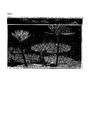
例えば、後述する図2に示す画面の画像表示領域2aに表示されている画像には、図3〜5の各図に示すマスクがかけられており、それぞれのマスクの濃度に応じた程度で画像処理が施されている。なお、図3〜5に示すマスクにおいては、黒の濃さによって、マスクの濃度が表されている。例えば、原画像に対して図3に示すマスクをかければ、画像の下部により強い画像処理が施され、上に行くに従って画像処理の程度が低下することになる。
For example, the image displayed in the
本実施の形態では、図2の画像表示領域2aに表示されている画像には、図3のマスクを用いて階調変換処理が施されている。すなわち、図2の画像には、画像の下部から上部に行くに従って、その程度が弱くなるように階調変換処理が施されている。また、図2の画像表示領域2aに表示されている画像には、図4のマスクを用いてカラーバランス調整処理が施されている。すなわち、図2の画像には、右側の花2fに対して、カラーバランス調整処理が施されている。また、図2の画像表示領域2aに表示されている画像には、図5のマスクを用いてシャープネス調整処理が施されている。すなわち、図2の画像には、右側の花2f、中央の花(つぼみ)2g、および左側の花2hに対して、シャープネス調整処理が施されている。
In the present embodiment, the image displayed in the
本実施の形態における画像処理情報表示装置100においては、使用者は、HDD104に記録されている画像データの中から任意の画像データを選択して、モニタ105上に表示することができる。制御装置103は、使用者によって操作部材101が操作されて任意の画像の表示が選択されると、その画像の画像データをHDD104から読み出し、画像表示画面上に配置してモニタ105上に表示する。
In the image processing
制御装置103は、例えば、図2に示す画像表示画面をモニタ105上に表示し、画像表示領域2aにHDD104から読み出した画像を表示する。また、この画像表示画面には、画像表示領域2aに表示した画像に施されている画像処理の名称を一覧表示したエディットリスト2bが配置されている。このエディットリスト2b内には、画像処理名一覧の他に、使用者が操作部材101に含まれるマウスを操作して押下することができるボタン2cから2eが配置されている。これらの各ボタンについては後述する。
For example, the
使用者は、操作部材101に含まれるマウスを操作して、画像表示画面上でマウスポインタを移動させることができる。使用者は、この画像表示画面上でマウスポインタを移動させて、エディットリスト2b内の「アイコン表示モード」ボタン2cを押下することにより、画像処理情報表示装置100のモードをアイコン表示モードに設定することができる。制御装置103は、使用者によって「アイコン表示モード」ボタン2cが押下されたことを検出した場合に以下の処理を実行する。
The user can move the mouse pointer on the image display screen by operating the mouse included in the
制御装置103は、使用者によるマウス操作によって、マウスポインタが画像内の画像処理が適用されている領域内に入ったか否かを判定する。具体的には、制御装置103は、マウスポインタの移動に伴って、各位置におけるマスクの濃度を検出する。そして、マウスポインタの位置におけるマスクの濃度が、あらかじめ設定されている閾値以下となったことを検出した場合に、マウスポインタは画像内の画像処理が適用されている領域内に入ったと判定する。
The
制御装置103は、制御装置103が画像内の画像処理が適用されている領域内にマウスポインタが入ったことを検出した場合には、その領域内に適用されている画像処理に関連する情報を画像表示画面上に表示する。具体的には、制御装置103は、マウスポインタが画像処理が適用されている領域内に入ったことを検出した場合には、画像内に階調変換処理が適用されている範囲(領域)を識別可能に表示するアウトライン(枠)を表示するとともに、その領域内に適用されている画像処理を示すアイコンを表示する。
When the
例えば、制御装置103は、図6に示すように、マウスポインタ6aが画像内の図3に示したマスクによって階調変換処理が施されている範囲内に入ったことを検出した場合には、画像内に階調変換処理が適用されている範囲を識別可能に表示するアウトライン6bを表示する。また、制御装置103は、マウスポインタ6aの近傍に、アウトライン6bで示す範囲内に階調変換処理が適用されていることを示すアイコン6cを表示する。
For example, as shown in FIG. 6, when the
なお、制御装置103は、領域内に複数の画像処理が適用されている場合には、それぞれの画像処理に対応した複数のアイコンを表示する。例えば、図7に示すように、マウスポインタ6aが画像内の図3に示したマスクによって階調変換処理が施されている範囲であって、かつ図5に示したマスクによってシャープネス調整処理が施されている範囲内、すなわち左側の花2hの範囲内に入ったことを検出した場合について説明する。
When a plurality of image processes are applied in the area, the
この場合には、制御装置103は、図7に示すように、画像内に階調変換処理が適用されている範囲を示すアウトライン6b、およびシャープネス調整処理が施されている範囲を示すアウトライン7aから7cを表示する。また、制御装置103は、マウスポインタ6aの近傍に、アウトライン6bで示す範囲内に階調変換処理が適用されていることを示すアイコン6c、およびアウトライン7aから7cで示す範囲内にシャープネス調整処理が施されていることを示すアイコン7dを表示する。
In this case, as shown in FIG. 7, the
また、図8に示すように、マウスポインタ6aが画像内の図3に示したマスクによって階調変換処理が施されている範囲であって、かつ図5に示したマスクによってシャープネス調整処理が施されている範囲内であって、かつ図4に示したカラーバランス調整処理が施されている範囲内、すなわち右側の花2fの範囲内に入ったことを検出した場合について説明する。
Further, as shown in FIG. 8, the
この場合には、制御装置103は、図8に示すように、画像内に階調変換処理が適用されている範囲を示すアウトライン6b、シャープネス調整処理が施されている範囲を示すアウトライン7aから7c、およびカラーバランス調整処理が施されている範囲を示すアウトライン8aを表示する。また、制御装置103は、マウスポインタ6aの近傍に、アウトライン6bで示す範囲内に階調変換処理が適用されていることを示すアイコン6c、アウトライン7aから7cで示す範囲内にシャープネス調整処理が施されていることを示すアイコン7d、およびアウトライン8aで示す範囲内にカラーバランス調整処理が施されていることを示すアイコン8bを表示する。
In this case, as illustrated in FIG. 8, the
なお、制御装置103は、マウスポインタが画像内の画像処理が施されている範囲内に入ったことを検出した場合には、上述したようにその範囲に適用されている画像処理に応じたアイコンを表示すると共に、エディットリスト2b内に表示されている画像処理名のうち、その範囲に適用されている画像処理の名前を強調表示(ハイライト表示)する。
When the
図9の例では、制御装置103は、マウスポインタ6aが左側の花2hの範囲内に入ったことを検出した場合には、マウスポインタ6aの近傍に、上述したアイコン6c、およびアイコン7dを表示すると共に、エディットリスト2b内の階調変換処理(Levels&Curves)とシャープネス調整処理(Unsharp Mask)を強調表示している。
In the example of FIG. 9, when the
あるいは、図10に示すように、制御装置103は、マウスポインタ6aが左側の花2hの範囲内に入ったことを検出した場合には、マウスポインタ6aの近傍に、上述したアイコン6c、およびアイコン7dを表示するとともに、エディットリスト2b内に、階調変換処理(Levels&Curves)の画像処理パラメータを調整するための画像編集パレット10aと、シャープネス調整処理(Unsharp Mask)の画像処理パラメータを調整するための画像編集パレット10bとを表示するようにしてもよい。
Alternatively, as shown in FIG. 10, when the
なお、制御装置103は、エディットリスト2b内に各画像処理名に対応付けてチェックボックスを表示しておき、デフォルトでチェックボックスにチェックを入れておくことにより、画像に対して画像処理が施されていることを示す。この場合、制御装置103は、使用者によるチェックボックスへのチェックのオン・オフの切り替えを受け付けるようにし、チェックがオフに変更された場合には、画像への対応する画像処理の適用をオフに切り替える。
The
制御装置103は、使用者によってマウスポインタが移動された場合には、マウスポインタが当該領域内にある間は、画像処理を示すアイコンをマウスポインタに追従させて移動させる。これに対して、マウスポインタが当該領域の外に出た後は、アイコンを消去する。
When the mouse pointer is moved by the user, the
使用者は、画像表示画面上にアイコンが表示されている間に、マウスをクリックすることによって、アイコンの表示位置を固定することができる。制御装置103は、使用者によってアイコン表示中にマウスがクリックされたことを検出した場合には、図11に示すように、画像上のクリック位置に十字ポインタ11aを表示する。また、制御装置103は、上述したアイコンやアウトラインの表示を終了して、十字ポインタ11aの近傍に簡易メニュー11bを表示する。
The user can fix the icon display position by clicking the mouse while the icon is displayed on the image display screen. When the
簡易メニュー11bは、画像が隠れることが無いように背景が透明になっている。この簡易メニュー11bには、使用者によってクリックされた位置に適用されている画像処理を示すアイコン(画像処理アイコン)、トグルボタン、および画像処理名が画像処理のステップ順に表示される。すなわち、図11の例では、十字ポインタ11aの表示位置の画像には、階調変換処理(Levels&Curves)、カラーバランス調整処理(Color Balance)、シャープネス調整処理(Unsharp Mask)の順に画像処理が施されていることを示している。
The
使用者は、画像上に表示されている簡易メニュー11bをマウスでドラッグすることによって、その表示位置を変更することができる。また、使用者は、画像上に簡易メニュー11bが表示されている状態で、画像上の簡易メニュー11b以外の箇所をクリックすることによって、簡易メニュー11bの表示を終了することができる。制御装置103は、使用者によって画像上の簡易メニュー11b以外の箇所がクリックされたことを検出した場合には、画像表示画面上から簡易メニュー11bを消去し、上述したアイコンやアウトラインの表示を再開する。なお、制御装置103は、使用者によるキーボードの所定のキー、例えばEscキーの押下を受け付けたときに、画像表示画面上から簡易メニュー11bを消去し、上述したアイコンやアウトラインの表示を再開するようにしてもよい。
The user can change the display position by dragging the
制御装置103は、使用者によってマウスが操作され、マウスポインタが簡易メニュー11b内のいずれかのトグルボタン上に位置したことを検出した場合には、そのトグルボタンに対応する画像処理アイコンの色を赤色に変更すると共に、そのトグルボタンに対応する画像処理のマスクを画像上に表示する。例えば、制御装置103は、マスク内の画像処理が適用されている範囲を透明で表示し、画像処理が適用されていない範囲を赤で表示して画像上に重畳する。これによって、使用者は、選択したトグルボタンに対応する画像処理が画像内のどの範囲に適用されているかを把握することができる。
When the
制御装置103は、使用者によってさらにマウスが操作され、マウスポインタがトグルボタン上から離れた場合には、トグルボタンに対応して表示したマスクを画像上から消去し、アイコンの色を元に戻す。なお、制御装置103は、使用者によってマウスが操作され、簡易メニュー11b内のいずれかのトグルボタンがクリックされたことを検出した場合には、そのトグルボタンに対応して表示した画像処理のマスクを画像上に表示したままにする。すなわち、制御装置103は、トグルボタンがクリックされた場合は、マウスポインタがトグルボタン上から離れた後も、画像上にマスクを表示したままにする。
When the user further operates the mouse and the mouse pointer moves away from the toggle button, the
このとき、制御装置103は、使用者によるブラシツールなどの選択ツールを用いたマスクの編集を受け付ける。例えば、図12に示すように、使用者は、ブラシツールを用いて、マスク上に図形12aを追加することができる。制御装置103は、使用者によって、再度トグルボタンがクリックされた場合は、マスクの画像上への表示、およびマスクの編集受け付けを終了する。
At this time, the
また、使用者は、簡易メニュー11b内に表示されているいずれかの画像処理アイコンをクリックすることによって、対応する画像処理の画像への適用のオン・オフを切り替えることができる。すなわち、制御装置103は、使用者によって簡易メニュー11b内のいずれかの画像処理アイコンがクリックされたことを検出した場合には、画像に対して適用されている画像処理の内、クリックされたアイコンに対応する画像処理をオフにする。また、制御装置103は、使用者によって再度同じ画像処理アイコンがクリックされたことを検出した場合には、そのアイコンに対応する画像処理をオンにする。
In addition, the user can switch on / off the application of the corresponding image processing to the image by clicking one of the image processing icons displayed in the
なお、制御装置103は、使用者によって簡易メニュー11b内のいずれかの画像処理アイコンがクリックされることにより画像処理のオン・オフが切り替えられた場合には、それに対応してエディットリスト2b内のチェックボックスへのチェックのオン・オフも切り替えるようにする。例えば、制御装置103は、画像処理がオフに切り替えられた場合には、エディットリスト2b内のチェックボックスのうち、オフされた画像処理に対応するチェックボックスのチェックを外す。また、制御装置103は、画像処理がオンに切り替えられた場合には、エディットリスト2b内のチェックボックスのうち、オンされた画像処理に対応するチェックボックスにチェックを入れる。
When the user clicks on any of the image processing icons in the
使用者は、簡易メニュー11b内に表示されているいずれかの画像処理名をクリックすることによって、対応する画像処理のパラメータ値を簡易的に変更するための簡易編集パレットを表示させることができる。すなわち、制御装置103は、使用者によって簡易メニュー11b内のいずれかの画像処理名がクリックされたことを検出した場合には、図13から図15に示すような簡易編集パレットを画像上に重畳して表示する。なお、この簡易編集パレットも、簡易メニュー11bと同様に、画像が隠れることが無いように背景が透明になっている。
The user can display a simple editing palette for simply changing the parameter value of the corresponding image processing by clicking any image processing name displayed in the
図13は、使用者が簡易メニュー11b内に表示されている「Levels&Curves」をクリックした場合に表示される簡易編集パレットの具体例を示す図である。使用者は、この図13に示す簡易編集パレット13a上で、階調変換処理の画像処理パラメータである階調変換特性を示すガンマカーブ13bの形状をマウス操作により変更することができる。
FIG. 13 is a diagram showing a specific example of the simple editing palette displayed when the user clicks “Levels & Curves” displayed in the
図14は、使用者が簡易メニュー11b内に表示されている「Color Balance」をクリックした場合に表示される簡易編集パレットの具体例を示す図である。使用者は、この図14に示す簡易編集パレット14a上で、RGBの各色成分ごとに表示されているスライダーをマウスで操作することにより、各色成分の値を変更することができる。
FIG. 14 is a diagram showing a specific example of the simple editing palette displayed when the user clicks “Color Balance” displayed in the
図15は、使用者が簡易メニュー11b内に表示されている「Unsharp Mask」をクリックした場合に表示される簡易編集パレットの具体例を示す図である。使用者は、この図15に示す簡易編集パレット15a上に表示されているスライダーをマウスで操作することにより、シャープネスの強度を調整することができる。
FIG. 15 is a diagram showing a specific example of the simple editing palette displayed when the user clicks “Unsharp Mask” displayed in the
なお、制御装置103は、画像上に簡易編集パレットが表示されているときに、画像上の簡易編集パレット以外の部分がクリックされたことを検出した場合には、簡易編集パレットの表示を終了して、画像上に簡易メニュー11bを表示する。
If the
また、制御装置103は、使用者によって簡易メニュー11b内に表示されている画像処理名がダブルクリックされたことを検出した場合には、図10に示したように、エディットリスト2b内に、ダブルクリックされた画像処理名に対応する画像処理の画像処理パラメータを調整するための画像編集パレットを表示する。
Further, when the
使用者は、エディットリスト2b内に表示されている「アンカーポイント設定モード」ボタン2eをマウスで押下することによって、画像処理情報表示装置100のモードをアンカーポイント設定モードに設定することができる。制御装置103は、使用者によって「アンカーポイント設定モード」ボタン2eが押下されたことを検出すると、使用者によるアンカーポイントの設定を受け付ける。使用者は、画像上の任意の点をマウスでクリックすることによって、画像上にアンカーポイントを設定することができる。制御装置103は、使用者によってアンカーポイントが設定されると、アンカーポイントが設定された位置に施されている画像処理に関する簡易メニューを表示する。
The user can set the mode of the image processing
例えば、図16に示すように、使用者によって画像上に3つのアンカーポイント16aから16cが設定された場合について説明する。この場合、制御装置103は、アンカーポイント16aの設定位置に対応する簡易メニュー16d、アンカーポイント16bの設定位置に対応する簡易メニュー16e、およびアンカーポイント16cの設定位置に対応する簡易メニュー16fをそれぞれ画像上に表示する。使用者は、各アンカーポイントに対応して表示された簡易メニューを図11で上述した簡易メニュー11bと同様に操作することができる。
For example, as shown in FIG. 16, a case where three
また、使用者は、エディットリスト2b内に表示されている「アウトライン表示モード」ボタン2dをマウスで押下することによって、画像処理情報表示装置100のモードをアウトライン表示モードに設定することができる。制御装置103は、使用者によって「アウトライン表示モード」ボタン2dが押下されると、画像内に施されている全ての画像処理を対象として、各画像処理が施されている範囲を示すアウトラインを表示し、各アウトラインに対応付けて、そのアウトライン内に施されている画像処理の名前を表示する。
The user can set the mode of the image processing
例えば、制御装置103は、図17に示すように、画像内に、図3に示したマスクの濃度値が閾値以下の範囲を示すアウトライン6b、すなわち画像に対して階調変換処理が施されている範囲を示すアウトライン6bを表示する。そして、制御装置103は、アウトライン6bに対応付けて、当該範囲内に適用されている画像処理名、すなわち「Levels&Curves」を表示する。
For example, as shown in FIG. 17, the
また、制御装置103は、画像内に、図4に示したマスクの濃度値が閾値以下の範囲を示すアウトライン8a、すなわち画像に対してカラーバランス調整処理が施されている範囲を示すアウトライン8aを表示する。そして、制御装置103は、アウトライン8aに対応付けて、当該範囲内に適用されている画像処理名、すなわち「Color Balance」を表示する。
Further, the
また、制御装置103は、画像内に、図5に示したマスクの濃度値が閾値以下の範囲を示すアウトライン7aから7c、すなわち画像に対してシャープネス調整処理が施されている範囲を示すアウトライン7aから7cを表示する。そして、制御装置103は、アウトライン7aから7cに対応付けて、当該範囲内に適用されている画像処理名、すなわち「Unsharp Mask」を表示する。
Further, the
制御装置103は、使用者によって画像上に表示したアウトラインのうち、いずれかのアウトライン内がマウスでクリックされたことを検出した場合に、そのアウトライン内に施されている画像処理が1つである場合には、その画像処理用の簡易編集パレットを表示する。また、制御装置103は、使用者によっていずれかのアウトライン内がマウスでクリックされたことを検出した場合に、そのアウトライン内に施されている画像処理が複数である場合には、各画像処理に対応するアイコン、トグルボタン、および画像処理名を表示した簡易メニューを表示する。
When the
図18は、画像表示画面上で使用者によってエディットリスト2b内の「アイコン表示モード」ボタン2cが押下されると実行される処理の流れを示すフローチャートである。この図18に示す処理を実行するためのプログラムのデータは、HDD104に記録されており、制御装置103は、このプログラムのデータをHDD104からSDRAMに読み込んで展開することによって、処理を実行する。図18から図25のフローチャートで示されるプログラムは、画像処理情報表示装置100にインストール可能なようにCD−ROM等の記憶媒体に記録されている。
FIG. 18 is a flowchart showing a flow of processing executed when the “icon display mode”
ステップS10において、制御装置103は、図19で後述するアイコン表示処理を実行して、マウスポインタが画像内の画像処理が適用されている領域内に入ったときに、上述したように、画像上にアイコンやアウトラインを表示する。その後、ステップS20へ進み、制御装置103は、使用者によって「アイコン表示モード」ボタン2cが再度押下されることによって、アイコン表示モードの終了が指示されたか否かを判断する。肯定判断した場合には、ステップS140へ進み、制御装置103は、画像上に表示しているアイコンやアウトラインを非表示にして、処理を終了する。これに対して、ステップS20で否定判断した場合には、ステップS30へ進む。
In step S10, the
ステップS30では、制御装置103は、画像内の画像処理が適用されている範囲内で使用者によってマウスがクリックされたか否かを判断する。否定判断した場合には、ステップS10へ戻る。これに対して、肯定判断した場合には、ステップS40へ進む。ステップS40では、画像上にアイコンが表示中であるか否かを示すアイコンフラグに1が設定されているか否かを判断する。なお、このアイコンフラグは、図19で後述するアイコン表示処理において設定され、アイコン表示中はアイコンフラグが1に設定され、アイコンが非表示の場合はアイコンフラグが0に設定される。
In step S30, the
ステップS40で否定判断した場合には、ステップS10へ戻る。これに対して、ステップS40で肯定判断した場合には、ステップS50へ進む。ステップS50では、制御装置103は、図11で上述したように、画像上のクリック位置に十字ポインタ11aを表示し、十字ポインタ11aの近傍に簡易メニュー11bを表示する。その後、ステップS60へ進む。
If a negative determination is made in step S40, the process returns to step S10. On the other hand, if a positive determination is made in step S40, the process proceeds to step S50. In step S50, as described above with reference to FIG. 11, the
ステップS60では、制御装置103は、マウスポインタが簡易メニュー11b内に表示されているいずれかのトグルボタン上に位置しているか否かを判断する。肯定判断した場合には、ステップS70へ進み、制御装置103は、図20で後述するマスク表示処理を実行した後、後述するステップS150へ進む。これに対して、否定判断した場合には、ステップS80へ進む。
In step S60, the
ステップS80では、制御装置103は、使用者によって簡易メニュー11b内に表示されているいずれかのアイコンがクリックされたか否かを判断する。肯定判断した場合には、ステップS90へ進み、制御装置103は、図21で後述する画像処理オン・オフ切替処理を実行した後、後述するステップS150へ進む。これに対して、否定判断した場合には、ステップS100へ進む。
In step S80, the
ステップS100では、制御装置103は、使用者によって簡易メニュー11b内に表示されているいずれかの画像処理名がクリックされたか否かを判断する。肯定判断した場合には、ステップS110へ進み、制御装置103は、図22で後述する簡易編集パレット表示処理を実行した後、後述するステップS150へ進む。これに対して、否定判断した場合には、ステップS120へ進む。
In step S100, the
ステップS120では、制御装置103は、使用者によって簡易メニュー11b内に表示されているいずれかの画像処理名がダブルクリックされたか否かを判断する。否定判断した場合には、後述するステップS150へ進む。これに対して、肯定判断した場合には、ステップS130へ進み、制御装置103は、図23で後述する画像処理パレット表示処理を実行して処理を終了する。
In step S120, the
ステップS150では、制御装置103は、使用者によるマウス操作によって、画像上がクリックされたか否かを判断する。否定判断した場合には、ステップS60へ戻る。これに対して、肯定判断した場合には、ステップS160へ進み、制御装置103は、画像上に表示している簡易メニューを非表示にして、ステップS10へ戻る。
In step S150, the
図19は、図18のステップS10で実行されるアイコン表示処理の流れを示すフローチャートである。ステップS210において、制御装置103は、マスクのレイヤ数を取得する。すなわち、制御装置103は、画像に対して適用されているマスクの数がいくつであるかを判定する。その後、ステップS220へ進み、制御装置103は、画像上におけるマウスポインタの位置を示す情報として、画像上におけるマウスポインタの座標値を取得する。その後、ステップS230へ進む。
FIG. 19 is a flowchart showing the flow of icon display processing executed in step S10 of FIG. In step S210, the
ステップS230では、制御装置103は、上述したアイコンフラグに0を設定して、ステップS240へ進む。ステップS240では、制御装置103は、画像に対して適用されている1つのマスクを対象として、現在のマウスポインタ位置におけるマスクの濃度値を取得する。その後、ステップS250へ進み、制御装置103は、取得したマスクの濃度値が閾値以下であるか否かを判断する。肯定判断した場合には、ステップ260へ進む。
In step S230, the
ステップS260では、制御装置103は、ステップS240で濃度値を取得したマスクに対して適用されている画像処理を示すアイコンを画像上に表示して、ステップS270へ進む。ステップS270では、制御装置103は、エディットリスト2b内に表示されている画像処理名のうち、ステップS260でアイコンを表示した画像処理の名前をハイライト表示して、ステップS280へ進む。
In step S260, the
ステップS280では、制御装置103は、ステップS240で濃度値を取得したマスクに基づいて、濃度値が閾値以下の範囲を枠で囲むことによって、上述したアウトラインを表示して、ステップS290へ進む。ステップS290では、制御装置103は、アイコンフラグに1を設定して、後述するステップS340へ進む。
In step S280, the
一方、ステップS250で否定判断した場合には、ステップS300へ進む。ステップS300では、制御装置103は、アイコンフラグに1が設定されているか否かを判断する。否定判断した場合には、後述するステップS340へ進む。これに対して、肯定判断した場合には、ステップS310へ進み、制御装置103は、画像上に表示されているアイコンを非表示にして、ステップS320へ進む。
On the other hand, if a negative determination is made in step S250, the process proceeds to step S300. In step S300, the
ステップS320では、制御装置103は、エディットリスト2b内でハイライト表示されている画像処理名のハイライト表示を終了して、ステップS330へ進む。ステップS330では、制御装置103は、画像上に表示されているアウトラインを非表示して、ステップS340へ進む。
In step S320, the
ステップS340では、制御装置103は、画像に対して適用されている全てのマスクを対象として、ステップS240からS330の処理が完了したか否かを判断する。否定判断した場合には、ステップS240へ戻って処理を繰り返す。これに対して、肯定判断した場合には、図18に示す処理に復帰する。
In step S340, the
図20は、図18のステップS70で実行されるマスク表示処理の流れを示すフローチャートである。ステップS410において、制御装置103は、マウスポインタが位置しているトグルボタンに対応する画像処理アイコンの色を赤色に変更すると共に、そのトグルボタンに対応する画像処理のマスクを画像上に表示する。その後、ステップS420へ進み、制御装置103は、使用者によってトグルボタンがクリックされたことにより、トグルボタンがオンされたか否かを判断する。肯定判断した場合には、ステップS430へ進む。
FIG. 20 is a flowchart showing the mask display process executed in step S70 of FIG. In step S410, the
ステップS430では、制御装置103は、使用者によるブラシツールなどの選択ツールを用いたマスクの編集操作があったか否かを判断する。肯定判断した場合には、ステップS440へ進み、使用者による編集操作に基づいて、マスクの修正を行って、ステップS450へ進む。これに対して、ステップS430で否定判断した場合には、そのままステップS450へ進む。
In step S430,
ステップS450では、制御装置103は、使用者によって、トグルボタンが再度クリックされることにより、トグルボタンがオフされたか否かを判断する。否定判断した場合には、ステップS430へ戻る。これに対して、肯定判断した場合には、ステップS460へ進み、制御装置103は、図24で後述する画像処理を行って、ステップS420へ戻る。
In step S450, the
一方、ステップS420で否定判断した場合には、ステップS470へ進む。ステップS470では、制御装置103は、画像内における現在のマウスポインタの座標値を取得して、ステップS480へ進む。ステップS480では、制御装置103は、マウスポインタがいずれかのトグルボタン上に位置しているか否かを判断する。肯定判断した場合には、ステップS420へ戻る。これに対して、否定判断した場合には、ステップS490へ進む。ステップS490では、制御装置103は、画像上に表示しているマスクを非表示にして、処理を終了する。
On the other hand, if a negative determination is made in step S420, the process proceeds to step S470. In step S470, the
図21は、図18のステップS90で実行される画像処理オン・オフ切替処理の流れを示すフローチャートである。ステップS510において、制御装置103は、画像表示領域2a内に表示されている画像に対して、画像処理が適用済みであるか否かを判断する。肯定判断した場合には、ステップS520へ進み、制御装置103は、画像に対する画像処理の適用をオフにして、ステップS530へ進む。ステップS530では、制御装置103は、使用者によってクリックされたトグルボタンを凹表示(選択状態)に切り替えて、図18に示す処理に復帰する。
FIG. 21 is a flowchart showing the flow of the image processing on / off switching process executed in step S90 of FIG. In step S510, the
これに対して、ステップS510で否定判断した場合には、ステップS540へ進み、制御装置103は、画像に対する画像処理の適用をオンにして、ステップS550へ進む。ステップS550では、制御装置103は、使用者によってクリックされたトグルボタンを凸表示(非選択状態)に切り替えて、図18に示す処理に復帰する。
On the other hand, if a negative determination is made in step S510, the process proceeds to step S540, and the
図22は、図18のステップS110で実行される簡易編集パレット表示処理の流れを示すフローチャートである。ステップS610において、制御装置103は、画像上に表示されている簡易メニューを非表示にして、ステップS620へ進む。ステップS620では、制御装置103は、図13から図15の各図で上述したように、画像上に簡易編集パレットを表示して、ステップS630へ進む。
FIG. 22 is a flowchart showing the flow of the simple edit palette display process executed in step S110 of FIG. In step S610, the
ステップS630では、制御装置103は、使用者によって簡易編集パレットを用いて画像処理パラメータが変更されることによって、画像が編集されたか否かを判断する。否定判断した場合には、後述するステップS650へ進む。これに対して、肯定判断した場合には、ステップS640へ進み、図24で後述する画像処理を行って、ステップS650へ進む。
In step S630, the
ステップS650では、制御装置103は、使用者によって画像上でマウスがクリックされたか否かを判断する。否定判断した場合には、上述したステップS630へ戻る。これに対して、肯定判断した場合には、ステップS660へ進む。ステップS660では、制御装置103は、画像上に表示している簡易編集パレットを非表示にして、ステップS670へ進む。ステップS670では、制御装置103は、簡易メニューを画像上に表示して、図18に示す処理に復帰する。
In step S650,
図23は、図18のステップS130で実行される画像処理パレット表示処理の流れを示すフローチャートである。ステップS710において、制御装置103は、画像上に表示されている簡易メニューを非表示にして、ステップS720へ進む。ステップS720では、制御装置103は、図10に示したように、エディットリスト2b内に、ダブルクリックされた画像処理名に対応する画像処理の画像処理パラメータを調整するための画像編集パレットを表示して、ステップS730へ進む。ステップS730では、制御装置103は、画像上に表示されているアウトラインを非表示にした後、図18に示す処理に復帰する。
FIG. 23 is a flowchart showing the flow of the image processing palette display process executed in step S130 of FIG. In step S710, the
図24は、図20のステップ460、および図22のステップS640で実行される画像処理の流れを示すフローチャートである。ステップS810において、制御装置103は、画像表示画面上に表示されている画像の各画素の画素値を取得する。その後、ステップS820へ進み、制御装置103は、画像に対して適用する画像処理のパラメータ値を、使用者による編集内容に基づいて変更する。その後、ステップS830へ進む。
FIG. 24 is a flowchart showing the flow of image processing executed in step 460 of FIG. 20 and step S640 of FIG. In step S810, the
ステップS830では、制御装置103は、画像に対してマスクを適用して、変更後の画像処理パラメータ値を用いた画素値の演算を行う。すなわち、制御装置103は、画像に対して複数のマスクが適用されている場合には、1つ目のマスクを適用した画像の各画素の画素値を演算した後、2つ目のマスクを適用した画像の各画素の画素値を演算する。制御装置103は、この処理を適用されているマスクの数だけ繰り返し行う。その後、ステップS840へ進む。
In step S830, the
ステップS840では、制御装置103は、画像に対して描画モードを適用する。すなわち、制御装置103は、画像に対して、あらかじめ設定されている描画モードを適用して、ステップS850へ進む。ステップS850では、制御装置103は、画像に対して、あらかじめ設定されている不透明度を適用する。このように適用した描画モードと不透明度とによって、画像に対するマスクのかけ方が決定される。例えば、描画モードがNORMALに設定されており、不透明度が100に設定されている場合には、一番上に重畳されたマスクが画像処理結果に反映されることになる。一方、描画モードがNORMALに設定されており、不透明度が0に設定されている場合には、一番下に重畳されたマスクが画像処理結果に反映されることになる。
In step S840,
その後、ステップS860へ進み、制御装置103は、上記演算の結果得られる画素値を出力して、ステップS870へ進む。ステップS870では、制御装置103は、出力した画素値に基づいて、画像処理適用後の画像で画像表示画面上に表示されている画像を更新する。その後、ステップS880へ進み、制御装置103は、使用者による画像の編集が終了したか否かを判断する。否定判断した場合には、ステップS820へ戻る。これに対して、肯定判断した場合には、図20または図22に示す処理に復帰する。
Thereafter, the process proceeds to step S860, and the
図25は、画像表示画面上で使用者によってエディットリスト2b内の「アウトライン表示モード」ボタン2dが押下されると実行される処理の流れを示すフローチャートである。この図25に示す処理を実行するためのプログラムのデータは、HDD104に記録されており、制御装置103は、このプログラムのデータをHDD104からSDRAMに読み込んで展開することによって、処理を実行する。
FIG. 25 is a flowchart showing a flow of processing executed when the “outline display mode”
なお、このフローチャートにおいては、ステップS50からステップS160の処理は、図18で上述したフローチャートにおける各ステップと同様のため同じステップ番号を付与し、説明を省略する。また、ステップS610からステップS660の処理は、図22で上述したフローチャートにおける各ステップと同様のため同じステップ番号を付与し、説明を省略する。 In this flowchart, the processing from step S50 to step S160 is the same as each step in the flowchart described above with reference to FIG. Further, the processing from step S610 to step S660 is the same as each step in the flowchart described above with reference to FIG.
ステップS910において、制御装置103は、マスクのレイヤ数を取得する。すなわち、制御装置103は、画像に対して適用されているマスクの数がいくつであるかを判定する。その後、ステップS920へ進み、制御装置103は、画像に対して適用されているマスクのうち、いずれか1つのマスクを取得してステップS930へ進む。ステップS930では、制御装置103は、ステップS920で取得したマスクの濃度値と、上述した図19のステップS250で判定に用いた閾値とが一致する画像上の位置に、アウトラインを描画して、ステップS940へ進む。
In step S910, the
ステップS940では、制御装置103は、画像に対して適用されている全てのマスクを対象として、ステップS920およびS930の処理が完了したか否かを判断する。否定判断した場合には、ステップS920へ戻って処理を繰り返す。これに対して、肯定判断した場合には、ステップS950へ進む。
In step S940, the
ステップS950では、制御装置103は、使用者によって再度「アウトライン表示モード」ボタン2dが押下されたことにより、アウトライン表示モードの終了が指示されたか否かを判断する。肯定判断した場合には、ステップS960へ進み、制御装置103は、画像上に描画したアウトラインを非表示にして、処理を終了する。これに対して、ステップS950で否定判断した場合には、ステップS970へ進む。
In step S950, the
ステップS970では、制御装置103は、使用者によってマウスがクリックされたか否かを判断する。否定判断した場合には、ステップS950へ戻る。これに対して、肯定判断した場合には、ステップS980へ進む。ステップS980では、制御装置103は、画像内における現在のマウスポインタの座標値を取得して、ステップS990へ進む。ステップS990では、制御装置103は、ステップS980で取得したマウスポインタの位置に基づいて、マウスポインタがステップS930で描画したアウトライン内に位置しているか否かを判断する。否定判断した場合には、ステップS950へ戻る。これに対して、肯定判断した場合には、ステップS1000へ進む。
In step S970, the
ステップS1000では、制御装置103は、ステップS930で描画した全てのアウトラインに対してステップS990の判定処理を行ったか否かを判断する。否定判断した場合には、ステップS990へ戻って処理を繰り返す。これに対して、肯定判断した場合には、ステップS1010へ進む。ステップS1010では、制御装置103は、ステップS990でマウスがアウトライン内にあると判定したアウトラインに該当する画像処理があるか否かを判断する。
In step S1000, the
否定判断した場合には、ステップS950へ戻って処理を繰り返す。これに対して、肯定判断した場合には、ステップS1020へ進む。ステップS1020では、ステップS1010で該当する画像処理であると判定した処理が複数あるか否かを判断する。肯定判断した場合には、ステップS610へ進み、ステップS610からS660の処理を実行した後、ステップS950へ戻る。これに対して、否定判断した場合には、ステップS50へ進み、ステップS50からステップS160の処理を実行した後、ステップS960へ戻る。 If a negative determination is made, the process returns to step S950 and the process is repeated. On the other hand, if a positive determination is made, the process proceeds to step S1020. In step S1020, it is determined whether or not there are a plurality of processes determined to be the corresponding image process in step S1010. If an affirmative determination is made, the process proceeds to step S610, the processes from step S610 to S660 are executed, and then the process returns to step S950. On the other hand, if a negative determination is made, the process proceeds to step S50, the process from step S50 to step S160 is executed, and then the process returns to step S960.
以上説明した本実施の形態によれば、以下のような作用効果を得ることができる。
(1)制御装置103は、画像データの画像の中で画像処理が適用されている領域を示す領域情報を管理し、使用者による操作に基づいて、使用者によって選択された対象画像内の任意の位置をポインタにより指示し、領域情報に基づいて、ポインタの位置が、対象画像内の画像処理が施されている領域内に入ったか否かを検出し、ポインタが画像処理が施されている領域内に入ったことを検出した場合には、その領域に対して施されている画像処理に関連する情報、すなわちアイコンを表示するようにした。一方、ポインタが画像処理が施されている領域内に入っていないことを検出した場合には、画像処理に関連する情報を非表示にするようにした。これによって、使用者は、簡易な操作により、画像内に適用されている画像処理に関連する情報を確認することができる。
According to the present embodiment described above, the following operational effects can be obtained.
(1) The
(2)制御装置103は、画像データの画像に対して複数の画像処理がそれぞれどの領域に適用されているかを示す領域情報を管理し、使用者からの指示があったときに、領域情報に基づいて、複数の画像処理が施されている領域の位置をそれぞれ識別可能に表示するようにした。すなわちアウトラインを表示するようにした。これによって、使用者は、画像内のどの領域に画像処理が施されているかを容易に確認することができる。
(2) The
(3)制御装置103は、画像データの画像に対して複数の画像処理がそれぞれどの領域に適用されているかを示す領域情報を管理し、使用者による操作に基づいて、使用者によって選択された対象画像上に少なくとも1つの指定点、すなわちアンカーポイントを設定し、領域情報に基づいて、設定した指定点に対して施されている画像処理に関連する情報を表示するようにした。これによって、使用者は、画像上の任意の点に施されている画像処理を確認することができる。
(3) The
(4)領域情報は、画像データの画像に対して複数の画像処理がそれぞれどの領域に適用されているかを示す情報であり、制御装置103は、ポインタの位置が複数の画像処理のそれぞれの領域内に入ったか否かを検出するようにした。これによって、画像に対して複数の画像処理が施されている場合に、ポインタが入ったか否かを各画像処理ごとに判定することができる。
(4) The area information is information indicating to which area a plurality of image processes are applied to the image of the image data, and the
(5)画像処理に関連する情報は、当該情報の表示中に使用者による操作を受け付けたときに、適用されている画像処理に関するメニューを表示するためのアイコンを含むようにした。これによって、使用者は、簡易な操作により、画像処理に関連するメニューを表示させることができる。 (5) Information related to image processing includes an icon for displaying a menu related to applied image processing when an operation by the user is accepted during display of the information. As a result, the user can display a menu related to image processing by a simple operation.
(6)画像処理に関連する情報は、画像内の画像処理が施されている領域を示すアウトラインを含むようにした。これによって、使用者は、画像内のどの領域に画像処理が施されているかを容易に確認することができる。 (6) Information related to image processing includes an outline indicating a region in the image where image processing is performed. Thereby, the user can easily confirm which region in the image is subjected to the image processing.
(7)画像処理に関連する情報は、使用者が画像に対して実行した複数の画像処理ごとに、それぞれの画像処理パラメータを調整するための簡易編集パレットを表示するための画像処理名を含むようにした。これによって、使用者は簡易な操作により、簡易編集パレットを表示させることができる。 (7) Information related to image processing includes an image processing name for displaying a simple editing palette for adjusting each image processing parameter for each of a plurality of image processing performed on the image by the user. I did it. Thereby, the user can display the simple edit palette by a simple operation.
(8)制御装置103は、使用者によって複数の画像処理のいずれかに対応する画像処理に関連する情報が選択された場合には、使用者によって選択された画像処理に応じた画像処理パラメータの編集用画面を表示するようにした。これによって、使用者は、画像に対して適用されている画像処理のパラメータ値を編集することができる。
(8) When information related to image processing corresponding to one of a plurality of image processing is selected by the user, the
(9)制御装置103は、使用者が対象画像に対して実行した画像処理ごとに画像処理に関連する情報を表示し、使用者によって複数の画像処理のいずれかに対応する画像処理に関連する情報が選択された場合には、使用者によって選択された画像処理の適用および非適用を切り替えるようにした。これによって、使用者は、容易に画像処理のオン・オフを切り替えることができる。
(9) The
(10)制御装置103は、画像処理の適用範囲と適用程度を示す情報、すなわちマスクに基づいて、領域情報を生成するようにした。これによって、制御装置103は、マスクを参照するだけで領域情報を生成することができ、処理の負荷を低減することができる。
(10) The
―変形例―
なお、上述した実施の形態の画像処理情報表示装置は、以下のように変形することもできる。
(1)上述した実施の形態では、制御装置103は、使用者によって「アウトライン表示モード」ボタン2dが押下された場合には、画像内に施されている全ての画像処理を対象として、各画像処理が施されている範囲を示すアウトラインを表示し、各アウトラインに対応付けて、そのアウトライン内に施されている画像処理の名前を表示する例について説明した。しかしながら、画像処理名の表示・非表示は、使用者が任意に切り替えることができるようにしてもよい。
-Modification-
The image processing information display device according to the above-described embodiment can be modified as follows.
(1) In the above-described embodiment, when the “outline display mode”
(2)上述した実施の形態では、制御装置103は、図19のステップS240で現在のポインタ位置におけるマスクの濃度値を取得し、ステップS250でこのマスクの濃度値が閾値以下であるかを判定することによって、画像上にアイコンおよびアウトラインを表示するか否かを決定する例について説明した。しかしながら、図24に示した処理によって画像全体に対して画像処理を施した場合、元の画素の色、明るさ、画像処理パラメータ値、画像処理の方法、描画モードの設定内容、または不透明度の設定内容等により、画像処理の効果は異なる。このため、画像処理後の画像に置いては、画像処理前の画像と比べて、色が大きく変化した画素とほとんど変化しない画素とが生じる可能性がある。
(2) In the embodiment described above, the
これにより、ステップS250において、制御装置103があるポインタ位置でマスクの濃度値が閾値以下であると判定した場合であっても、そのポインタ位置の画像は、画像処理前と画像処理後とでほとんど変化していない可能性があり、この場合には、そのようなポインタ位置も画像処理が施されている範囲内に含まれてしまうことになる。 Thereby, even if it is determined in step S250 that the density value of the mask is equal to or less than the threshold value at a certain pointer position, the image at the pointer position is almost before and after the image processing. There is a possibility that the position has not changed, and in this case, such a pointer position is also included in the range subjected to the image processing.
したがって、この問題を解決するために、制御装置103は、画像に対して施されている画像処理前の画像データの値と、画像処理後の画像データの値とを比較して、その変化量が閾値以上となる範囲を画像処理が施されている範囲とみなして、アイコンおよびアウトラインを表示するようにしてもよい。例えば、制御装置103は、画像処理前の画像の各画素の明度Paと、画像処理後の画像の各画素の明度Pbとを比較して、|Pa−Pb|が閾値以上となる画素を含む範囲を画像処理が施されている範囲とみなすようにしてもよい。
Therefore, in order to solve this problem, the
なお、本発明の特徴的な機能を損なわない限り、本発明は、上述した実施の形態における構成に何ら限定されない。 Note that the present invention is not limited to the configurations in the above-described embodiments as long as the characteristic functions of the present invention are not impaired.
100 画像処理情報表示装置、101 操作部材、102 接続IF、103 制御装置、104 HDD、105 モニタ
DESCRIPTION OF
Claims (13)
使用者による操作に基づいて、使用者によって選択された対象画像内の任意の位置をポインタにより指示する指示手順と、
前記領域情報に基づいて、前記ポインタの位置が、前記対象画像内の画像処理が施されている領域内に入ったか否かを検出する検出手順と、
前記検出手順により、前記ポインタが前記画像処理の施されている領域内に入ったことが検出された場合には、その領域に対して施されている画像処理に関連する情報を表示する情報表示手順と、
前記検出手順により、前記ポインタが前記画像処理の施されている領域内に入っていないことが検出された場合には、前記画像処理に関連する情報を非表示にする情報非表示手順とをコンピュータに実行させることを特徴とする画像処理情報表示用プログラム。 A management procedure for managing area information indicating an area to which image processing is applied in an image of image data;
An instruction procedure for pointing an arbitrary position in the target image selected by the user with a pointer based on an operation by the user;
Based on the area information, a detection procedure for detecting whether or not the position of the pointer has entered an area in the target image that has undergone image processing;
When the detection procedure detects that the pointer has entered the area where the image processing is performed, an information display for displaying information related to the image processing performed for the area Procedure and
An information non-display procedure for hiding information related to the image processing when the detection procedure detects that the pointer is not within the area subjected to the image processing. An image processing information display program that is executed by the program.
使用者からの指示があったときに、前記領域情報に基づいて、前記複数の画像処理が施されている領域の位置をそれぞれ識別可能に表示する領域表示手順をコンピュータに実行させることを特徴とする画像処理情報表示用プログラム。 A management procedure for managing region information indicating to which region each of the plurality of image processes is applied to the image of the image data;
When an instruction from a user is given, the computer causes a computer to execute an area display procedure for displaying the positions of the areas subjected to the plurality of image processing in an identifiable manner based on the area information. Program for displaying image processing information.
使用者による操作に基づいて、使用者によって選択された対象画像内の任意の位置をポインタにより指示する指示手順と、
前記対象画像内を指し示すポインタの位置が、使用者による操作部材の操作によって、前記画像処理が施されている領域内に入ったか否かを検出する検出手順と、
前記検出手順により、前記ポインタが前記画像処理の施されている領域内に入ったことが検出された場合には、その領域に対して施されている画像処理に関連する情報を表示する情報表示手順と、
前記検出手順により、前記ポインタが前記画像処理の施されている領域内に入っていないことが検出された場合には、前記画像処理に関連する情報を非表示にする情報非表示手順とをさらに有することを特徴とする画像処理情報表示用プログラム。 In the image processing information display program according to claim 2,
An instruction procedure for pointing an arbitrary position in the target image selected by the user with a pointer based on an operation by the user;
A detection procedure for detecting whether or not the position of the pointer pointing in the target image has entered the region where the image processing is performed by the operation of the operation member by the user;
When the detection procedure detects that the pointer has entered the area where the image processing is performed, an information display for displaying information related to the image processing performed for the area Procedure and
An information hiding procedure for hiding information related to the image processing when the detection procedure detects that the pointer does not fall within the area subjected to the image processing; An image processing information display program characterized by comprising:
使用者による操作に基づいて、使用者によって選択された対象画像上に少なくとも1つの指定点を設定する指定点設定手順と、
前記領域情報に基づいて、前記指定点設定手順が設定した前記指定点に対して施されている画像処理に関連する情報を表示する情報表示手順とをコンピュータに実行させることを特徴とする画像処理情報表示用プログラム。 A management procedure for managing region information indicating to which region each of the plurality of image processes is applied to the image of the image data;
A designated point setting procedure for setting at least one designated point on the target image selected by the user based on an operation by the user;
An image processing that causes a computer to execute an information display procedure for displaying information related to image processing applied to the designated point set by the designated point setting procedure based on the region information. Information display program.
前記領域情報は、画像データの画像に対して複数の画像処理がそれぞれどの領域に適用されているかを示す情報であり、前記検出手順は、前記ポインタの位置が前記複数の画像処理のそれぞれの領域内に入ったか否かを検出することを特徴とする画像処理情報表示用プログラム。 In the image processing information display program according to claim 1,
The area information is information indicating to which area a plurality of image processes are applied to the image of the image data, and the detection procedure is such that the position of the pointer is each area of the plurality of image processes. An image processing information display program for detecting whether or not an image has entered.
前記画像処理に関連する情報は、当該情報の表示中に使用者による操作を受け付けたときに、適用されている画像処理に関するメニューを表示するための情報を含むことを特徴とする画像処理情報表示用プログラム。 In the image processing information display program according to claim 1, 3, or 4,
The information related to the image processing includes information for displaying a menu related to the applied image processing when an operation by the user is accepted during the display of the information. Program.
前記画像処理に関連する情報は、画像内の画像処理が施されている領域を示す情報を含むことを特徴とする画像処理情報表示用プログラム。 In the image processing information display program according to claim 1 or 4,
The image processing information display program characterized in that the information related to the image processing includes information indicating a region in the image where the image processing is performed.
前記画像処理に関連する情報は、使用者が画像に対して実行した前記複数の画像処理ごとに、それぞれの画像処理パラメータを調整するための画面を表示するための情報を含むことを特徴とする画像処理情報表示用プログラム。 In the image processing information display program according to claim 3, 4, or 5,
The information related to the image processing includes information for displaying a screen for adjusting each image processing parameter for each of the plurality of image processing performed on the image by the user. Image processing information display program.
使用者によって前記複数の画像処理のいずれかに対応する前記画像処理に関連する情報が選択された場合には、使用者によって選択された画像処理に応じた前記画像処理パラメータの編集用画面を表示する編集用画面表示手順をさらに有することを特徴とする画像処理情報表示用プログラム。 In the image processing information display program according to claim 8,
When information related to the image processing corresponding to any of the plurality of image processing is selected by the user, the image processing parameter editing screen corresponding to the image processing selected by the user is displayed. An image processing information display program characterized by further comprising an editing screen display procedure.
前記情報表示手順は、使用者が前記対象画像に対して実行した画像処理ごとに前記画像処理に関連する情報を表示し、
使用者によって前記複数の画像処理のいずれかに対応する前記画像処理に関連する情報が選択された場合には、使用者によって選択された画像処理の適用および非適用を切り替える切り替え手順をさらに有することを特徴とする画像処理情報表示用プログラム。 In the image processing information display program according to claim 3, 4, or 5,
The information display procedure displays information related to the image processing for each image processing performed by the user on the target image,
A switching procedure for switching between application and non-application of the image processing selected by the user when information related to the image processing corresponding to any of the plurality of image processing is selected by the user; An image processing information display program characterized by the above.
前記管理手順は、画像処理の適用程度を示す情報に基づいて、前記領域情報を生成することを特徴とする画像処理情報表示用プログラム。 The image processing information display program according to claim 1, 2, or 4,
The management procedure generates the area information on the basis of information indicating an application degree of image processing.
前記管理手順は、画像に対して施されている画像処理前の画像データの値と、画像処理後の画像データの値とに基づいて、前記領域情報を生成することを特徴とする画像処理情報表示用プログラム。 The image processing information display program according to claim 1, 2, or 4,
The management procedure generates the area information based on a value of image data before image processing applied to an image and a value of image data after image processing. Display program.
Priority Applications (1)
| Application Number | Priority Date | Filing Date | Title |
|---|---|---|---|
| JP2007325801A JP2009146343A (en) | 2007-12-18 | 2007-12-18 | Image processing information display program and image processing information display device |
Applications Claiming Priority (1)
| Application Number | Priority Date | Filing Date | Title |
|---|---|---|---|
| JP2007325801A JP2009146343A (en) | 2007-12-18 | 2007-12-18 | Image processing information display program and image processing information display device |
Publications (1)
| Publication Number | Publication Date |
|---|---|
| JP2009146343A true JP2009146343A (en) | 2009-07-02 |
Family
ID=40916843
Family Applications (1)
| Application Number | Title | Priority Date | Filing Date |
|---|---|---|---|
| JP2007325801A Pending JP2009146343A (en) | 2007-12-18 | 2007-12-18 | Image processing information display program and image processing information display device |
Country Status (1)
| Country | Link |
|---|---|
| JP (1) | JP2009146343A (en) |
Cited By (2)
| Publication number | Priority date | Publication date | Assignee | Title |
|---|---|---|---|---|
| US20110050915A1 (en) * | 2009-08-31 | 2011-03-03 | Sony Corporation | Photographing condition setting apparatus, photographing condition setting method, and photographing condition setting program |
| WO2023109385A1 (en) * | 2021-12-17 | 2023-06-22 | 北京字跳网络技术有限公司 | Icon click detection method and apparatus, device, and storage medium |
-
2007
- 2007-12-18 JP JP2007325801A patent/JP2009146343A/en active Pending
Cited By (3)
| Publication number | Priority date | Publication date | Assignee | Title |
|---|---|---|---|---|
| US20110050915A1 (en) * | 2009-08-31 | 2011-03-03 | Sony Corporation | Photographing condition setting apparatus, photographing condition setting method, and photographing condition setting program |
| US8773566B2 (en) * | 2009-08-31 | 2014-07-08 | Sony Corporation | Photographing condition setting apparatus, photographing condition setting method, and photographing condition setting program |
| WO2023109385A1 (en) * | 2021-12-17 | 2023-06-22 | 北京字跳网络技术有限公司 | Icon click detection method and apparatus, device, and storage medium |
Similar Documents
| Publication | Publication Date | Title |
|---|---|---|
| JP5361159B2 (en) | Image display control device, control method therefor, program, and recording medium | |
| JP4720874B2 (en) | Information processing apparatus, information processing method, and information processing program | |
| JP2005292975A (en) | Button processing method and data processor | |
| JP2010016804A (en) | Apparatus and method for processing image, and recording medium | |
| JP2009077227A (en) | Imaging apparatus and its control method | |
| US20050193350A1 (en) | Display method and display device | |
| JP2007148783A (en) | Device and method for displaying image for computer and medium with image display program recorded thereon | |
| JP2007104630A (en) | Video surveillance system | |
| JP4508745B2 (en) | Information processing apparatus, image editing apparatus, control method therefor, computer program, and computer-readable storage medium | |
| JP2009077226A (en) | Imaging device and its control method and program and storage medium storing program | |
| JP2009146343A (en) | Image processing information display program and image processing information display device | |
| JP2013134579A (en) | User interface device | |
| JP2012010190A (en) | Imaging apparatus and control method thereof | |
| JP5769489B2 (en) | Image processing apparatus and control method thereof | |
| JP2011228897A (en) | Image processing program and image processing apparatus | |
| JP2008052446A (en) | Image processor and its control method | |
| JP2012014519A (en) | Display control device | |
| JP5531636B2 (en) | Image processing program and image processing apparatus | |
| JP2007114402A (en) | Display processing apparatus | |
| JP2008118355A (en) | Image processor and image processing method | |
| JP6779778B2 (en) | Display control device and its control method | |
| US20190130205A1 (en) | Image processing apparatus, method for controlling image processing apparatus, and non-transitory computer-readable storage medium | |
| JP5225053B2 (en) | Digital camera and display control device. | |
| JP6039410B2 (en) | Image processing apparatus and image processing method | |
| JP5580623B2 (en) | Image processing apparatus, image processing apparatus control method, program, and storage medium |