JP2009136459A - Noise reduction system, endoscope processor, and endoscope system - Google Patents
Noise reduction system, endoscope processor, and endoscope system Download PDFInfo
- Publication number
- JP2009136459A JP2009136459A JP2007315107A JP2007315107A JP2009136459A JP 2009136459 A JP2009136459 A JP 2009136459A JP 2007315107 A JP2007315107 A JP 2007315107A JP 2007315107 A JP2007315107 A JP 2007315107A JP 2009136459 A JP2009136459 A JP 2009136459A
- Authority
- JP
- Japan
- Prior art keywords
- image signal
- subject
- signal
- illumination light
- black
- Prior art date
- Legal status (The legal status is an assumption and is not a legal conclusion. Google has not performed a legal analysis and makes no representation as to the accuracy of the status listed.)
- Pending
Links
- 238000000034 method Methods 0.000 claims description 87
- 238000005286 illumination Methods 0.000 claims description 68
- 230000003287 optical effect Effects 0.000 claims description 33
- 238000003384 imaging method Methods 0.000 claims description 24
- 238000001514 detection method Methods 0.000 claims description 16
- 230000008569 process Effects 0.000 description 40
- 230000007274 generation of a signal involved in cell-cell signaling Effects 0.000 description 13
- 210000001260 vocal cord Anatomy 0.000 description 12
- 230000006870 function Effects 0.000 description 7
- 238000003780 insertion Methods 0.000 description 6
- 230000037431 insertion Effects 0.000 description 6
- 238000010586 diagram Methods 0.000 description 4
- 230000000694 effects Effects 0.000 description 4
- 230000007423 decrease Effects 0.000 description 3
- 230000001678 irradiating effect Effects 0.000 description 3
- 230000007257 malfunction Effects 0.000 description 3
- 230000007246 mechanism Effects 0.000 description 3
- 230000005540 biological transmission Effects 0.000 description 2
- 238000009826 distribution Methods 0.000 description 2
- 238000004519 manufacturing process Methods 0.000 description 2
- 230000004913 activation Effects 0.000 description 1
- 230000000903 blocking effect Effects 0.000 description 1
- 230000008030 elimination Effects 0.000 description 1
- 238000003379 elimination reaction Methods 0.000 description 1
- 229910052736 halogen Inorganic materials 0.000 description 1
- 150000002367 halogens Chemical class 0.000 description 1
- 239000011159 matrix material Substances 0.000 description 1
- 230000004048 modification Effects 0.000 description 1
- 238000012986 modification Methods 0.000 description 1
- 239000013307 optical fiber Substances 0.000 description 1
- 230000008929 regeneration Effects 0.000 description 1
- 238000011069 regeneration method Methods 0.000 description 1
- 238000003860 storage Methods 0.000 description 1
- 229910052724 xenon Inorganic materials 0.000 description 1
- FHNFHKCVQCLJFQ-UHFFFAOYSA-N xenon atom Chemical compound [Xe] FHNFHKCVQCLJFQ-UHFFFAOYSA-N 0.000 description 1
Images


Classifications
-
- A—HUMAN NECESSITIES
- A61—MEDICAL OR VETERINARY SCIENCE; HYGIENE
- A61B—DIAGNOSIS; SURGERY; IDENTIFICATION
- A61B1/00—Instruments for performing medical examinations of the interior of cavities or tubes of the body by visual or photographical inspection, e.g. endoscopes; Illuminating arrangements therefor
- A61B1/00002—Operational features of endoscopes
- A61B1/00004—Operational features of endoscopes characterised by electronic signal processing
- A61B1/00009—Operational features of endoscopes characterised by electronic signal processing of image signals during a use of endoscope
- A61B1/000095—Operational features of endoscopes characterised by electronic signal processing of image signals during a use of endoscope for image enhancement
-
- A—HUMAN NECESSITIES
- A61—MEDICAL OR VETERINARY SCIENCE; HYGIENE
- A61B—DIAGNOSIS; SURGERY; IDENTIFICATION
- A61B1/00—Instruments for performing medical examinations of the interior of cavities or tubes of the body by visual or photographical inspection, e.g. endoscopes; Illuminating arrangements therefor
- A61B1/04—Instruments for performing medical examinations of the interior of cavities or tubes of the body by visual or photographical inspection, e.g. endoscopes; Illuminating arrangements therefor combined with photographic or television appliances
- A61B1/045—Control thereof
-
- A—HUMAN NECESSITIES
- A61—MEDICAL OR VETERINARY SCIENCE; HYGIENE
- A61B—DIAGNOSIS; SURGERY; IDENTIFICATION
- A61B1/00—Instruments for performing medical examinations of the interior of cavities or tubes of the body by visual or photographical inspection, e.g. endoscopes; Illuminating arrangements therefor
- A61B1/06—Instruments for performing medical examinations of the interior of cavities or tubes of the body by visual or photographical inspection, e.g. endoscopes; Illuminating arrangements therefor with illuminating arrangements
- A61B1/0661—Endoscope light sources
- A61B1/0669—Endoscope light sources at proximal end of an endoscope
-
- H—ELECTRICITY
- H04—ELECTRIC COMMUNICATION TECHNIQUE
- H04N—PICTORIAL COMMUNICATION, e.g. TELEVISION
- H04N23/00—Cameras or camera modules comprising electronic image sensors; Control thereof
- H04N23/70—Circuitry for compensating brightness variation in the scene
- H04N23/74—Circuitry for compensating brightness variation in the scene by influencing the scene brightness using illuminating means
-
- H—ELECTRICITY
- H04—ELECTRIC COMMUNICATION TECHNIQUE
- H04N—PICTORIAL COMMUNICATION, e.g. TELEVISION
- H04N25/00—Circuitry of solid-state image sensors [SSIS]; Control thereof
- H04N25/70—SSIS architectures; Circuits associated therewith
- H04N25/76—Addressed sensors, e.g. MOS or CMOS sensors
-
- H—ELECTRICITY
- H04—ELECTRIC COMMUNICATION TECHNIQUE
- H04N—PICTORIAL COMMUNICATION, e.g. TELEVISION
- H04N23/00—Cameras or camera modules comprising electronic image sensors; Control thereof
- H04N23/50—Constructional details
- H04N23/555—Constructional details for picking-up images in sites, inaccessible due to their dimensions or hazardous conditions, e.g. endoscopes or borescopes
Landscapes
- Life Sciences & Earth Sciences (AREA)
- Health & Medical Sciences (AREA)
- Engineering & Computer Science (AREA)
- Surgery (AREA)
- Signal Processing (AREA)
- Radiology & Medical Imaging (AREA)
- Medical Informatics (AREA)
- Nuclear Medicine, Radiotherapy & Molecular Imaging (AREA)
- Optics & Photonics (AREA)
- Pathology (AREA)
- Physics & Mathematics (AREA)
- Veterinary Medicine (AREA)
- Biomedical Technology (AREA)
- Heart & Thoracic Surgery (AREA)
- Biophysics (AREA)
- Molecular Biology (AREA)
- Animal Behavior & Ethology (AREA)
- General Health & Medical Sciences (AREA)
- Public Health (AREA)
- Multimedia (AREA)
- Endoscopes (AREA)
- Instruments For Viewing The Inside Of Hollow Bodies (AREA)
- Transforming Light Signals Into Electric Signals (AREA)
Abstract
【課題】CMOS撮像素子のグローバル露光時のノイズの影響を低減化させる。
【解決手段】内視鏡システム10は光源ユニット40、撮像素子駆動回路21、システムコントローラ22、および画像信号処理ユニット50を有する。撮像素子32はCMOS撮像素子である。グローバル露光を開始させた後、システムコントローラ22は光源ユニット40を1フィールド期間発光停止させる。システムコントローラ22は撮像素子駆動回路21を制御して撮像素子32にグローバル露光による黒色画像信号を生成させる。画像信号処理ユニット50は黒色画像信号を格納する。システムコントローラ22は光源ユニット40のパルス発光を再開させる。システムコントローラ22は撮像素子駆動回路21を制御してパルス発光中に通常画像信号を生成させる。画像信号処理ユニット50は通常画像信号から黒色画像信号を減じて、固定パターンノイズを除去する。
【選択図】図1An object of the present invention is to reduce the influence of noise during global exposure of a CMOS image sensor.
An endoscope system includes a light source unit, an image sensor driving circuit, a system controller, and an image signal processing unit. The image sensor 32 is a CMOS image sensor. After starting the global exposure, the system controller 22 stops the light source unit 40 from emitting light for one field period. The system controller 22 controls the image sensor drive circuit 21 to cause the image sensor 32 to generate a black image signal by global exposure. The image signal processing unit 50 stores a black image signal. The system controller 22 restarts the pulse light emission of the light source unit 40. The system controller 22 controls the image sensor drive circuit 21 to generate a normal image signal during pulse emission. The image signal processing unit 50 subtracts the black image signal from the normal image signal to remove fixed pattern noise.
[Selection] Figure 1
Description
本発明は、電子内視鏡に設けられるCMOS撮像素子にグローバル露光を実行させるときに生じる固定パターンノイズの影響を低減化させるノイズ除去システムに関する。 The present invention relates to a noise removal system that reduces the influence of fixed pattern noise that occurs when a CMOS image sensor provided in an electronic endoscope performs global exposure.
挿入管の先端に撮像素子を設けた電子内視鏡が知られている。光源から放射される照明光を光ファイバによって挿入管の先端に伝達することにより、光の到達しない体内や構造物内の被写体を撮像することが可能である。 An electronic endoscope in which an image sensor is provided at the tip of an insertion tube is known. By transmitting the illumination light emitted from the light source to the distal end of the insertion tube through an optical fiber, it is possible to image a subject in the body or structure where the light does not reach.
被写体への照明光の照射方法によっては、特殊な画像を表示することが可能になる。例えば、周期的に発光と停止とを繰返すパルス発光により被写体を照射することが知られている。声帯を撮像するときに、声帯の振動の周波数と略同じ周波数でパルス発光を行い、その反射光を撮像することにより、高速で振動する声帯を低速で振動しているように表示することが可能である。 Depending on the method of illuminating the subject, a special image can be displayed. For example, it is known to irradiate a subject by pulse light emission that periodically repeats light emission and stop. When imaging the vocal cords, it is possible to display the vocal cords that vibrate at high speed as if they vibrated at low speed by emitting pulses at approximately the same frequency as the vocal cord vibration frequency and imaging the reflected light. It is.
パルス発光を行なう場合には高速で動く被写体を撮像することが多いため、全画素に同じ期間に受光させることが好ましい。一方で、照明光を常に被写体に照射する定常発光を行なう場合には静止物や低速で動く被写体が撮像されることが多いため、ノイズの影響の少ない画像信号を得ることが好ましい。 When performing pulsed light emission, a subject moving at high speed is often imaged. Therefore, it is preferable that all pixels receive light during the same period. On the other hand, when performing steady light emission that always irradiates a subject with illumination light, a stationary object or a subject that moves at low speed is often imaged. Therefore, it is preferable to obtain an image signal that is less affected by noise.
ノイズの影響が少なく且つグローバル露光により被写体を撮像するために従来の電子内視鏡ではCCD撮像素子を用いられていた。しかし、CCD撮像素子は、製造コストが高いこと、駆動電圧が高いこと、接続の必要な信号線数が多いなどの課題を有していた。 In order to pick up an image of a subject with little influence of noise and global exposure, a CCD image pickup device is used in a conventional electronic endoscope. However, the CCD image pickup device has problems such as high manufacturing cost, high drive voltage, and a large number of signal lines that need to be connected.
そこで、最近では製造コストや電力消費量の観点においてCCD撮像素子より有利なCMOS撮像素子を電子内視鏡に用いることが提案されている(特許文献1参照)。しかし、CMOS撮像素子では、グローバル露光を行うときに画像に現れるノイズの影響が大きいことが問題であった。
したがって、本発明では、CMOS撮像素子にグローバル露光させる場合に生じるノイズの影響を低減化させるノイズ除去システムの提供を目的とする。 Accordingly, an object of the present invention is to provide a noise removal system that reduces the influence of noise generated when a CMOS image sensor is exposed globally.
本発明の第1のノイズ除去システムは、電子内視鏡に設けられ被写体の光学像の受光により生成する信号電荷に基づいて光学像に対応する画像信号を生成するCMOS撮像素子の露光方法をグローバル露光に切替える露光切替えスイッチと、露光方法がグローバル露光に切替えられた後の少なくとも1フィールド期間または1フレーム期間内において画像信号に変換される信号電荷を生成するための受光期間中に被写体を照明するための照明光の被写体への照射を停止させる光源制御部と、照明光の被写体への照射が停止されている間に生成した信号電荷に基づく画像信号を黒色画像信号として格納するメモリと、メモリに格納された黒色画像信号に基づいて照明光が被写体に照射されている間に生成した信号電荷に基づく画像信号である通常画像信号に含まれる固定パターンノイズを除去するノイズ除去部とを備えることを特徴としている。 The first noise removal system of the present invention is a global exposure method for a CMOS image sensor that generates an image signal corresponding to an optical image based on a signal charge that is provided in an electronic endoscope and is generated by receiving an optical image of a subject. Illuminating the subject during a light receiving period for generating a signal charge that is converted into an image signal in at least one field period or one frame period after the exposure method is switched to global exposure and an exposure switching switch that switches to exposure A light source control unit for stopping irradiation of the illumination light to the subject, a memory for storing an image signal based on a signal charge generated while irradiation of the illumination light on the subject is stopped as a black image signal, and a memory An image signal based on a signal charge generated while illumination light is irradiated on the subject based on the black image signal stored in It is characterized in that it comprises a noise removing unit for removing the fixed pattern noise contained in an image signal.
なお、電子内視鏡の初期化を実行させる操作入力を検出する初期化入力部を備え、初期化入力部への電子内視鏡の初期化実行のための操作入力を検出するときに、光源制御部は検出後の少なくとも1フィールド期間または1フレーム期間内において画像信号に変換される信号電荷を生成するための受光期間中に照明光の被写体への照射を停止させ、メモリは照明光の被写体への照射が停止されている間に生成した信号電荷に基づく画像信号を黒色画像信号として格納し、ノイズ除去部はメモリに格納された黒色画像信号に基づいて通常画像信号に含まれる固定パターンノイズを除去することが好ましい。 An initialization input unit for detecting an operation input for executing initialization of the electronic endoscope is provided, and a light source is detected when detecting an operation input for initialization of the electronic endoscope to the initialization input unit. The control unit stops irradiation of the illumination light on the subject during the light receiving period for generating a signal charge to be converted into an image signal within at least one field period or one frame period after detection, and the memory The image signal based on the signal charge generated while irradiation of the image is stopped is stored as a black image signal, and the noise removal unit is a fixed pattern noise included in the normal image signal based on the black image signal stored in the memory. Is preferably removed.
また、黒色画像信号の輝度を算出する輝度算出部を備え、光源制御部は輝度算出部により算出された黒色画像信号の輝度が第1の閾値を超える場合に画像信号に変換される信号電荷を生成するための受光期間中における照明光の照射を再び停止し、メモリは照明光の照射が再び停止されている間に生成した信号電荷に基づく黒色画像信号を格納することが好ましい。 In addition, the light source control unit includes a luminance calculation unit that calculates the luminance of the black image signal, and the light source control unit calculates a signal charge that is converted into the image signal when the luminance of the black image signal calculated by the luminance calculation unit exceeds the first threshold. It is preferable that the illumination light irradiation is stopped again during the light receiving period for generation, and the memory stores a black image signal based on the signal charge generated while the illumination light irradiation is stopped again.
本発明の第2のノイズ除去システムは、電子内視鏡に設けられ照明光がパルス照射される被写体の光学像の受光により生成する信号電荷に基づいて光学像に対応する画像信号を生成するCMOS撮像素子の露光方法をグローバル露光に切替える露光切替えスイッチと、露光方法が前記グローバル露光に切替えられた後の少なくとも1フィールド期間または1フレーム期間内において照明光の前記被写体への照射が停止されている間に画像信号に変換される信号電荷を生成するための受光をCMOS撮像素子に実行させる撮像素子制御部と、照明光の前記被写体への照射が停止されている間に生成した信号電荷に基づく画像信号を黒色画像信号として格納するメモリと、メモリに格納された黒色画像信号に基づいて照明光が被写体に照射されている間に生成した信号電荷に基づく画像信号である通常画像信号に含まれる固定パターンノイズを除去するノイズ除去部とを備えることを特徴としている。 The second noise removal system of the present invention is a CMOS that is provided in an electronic endoscope and generates an image signal corresponding to an optical image based on a signal charge generated by receiving an optical image of a subject irradiated with pulses of illumination light. An exposure changeover switch that switches the exposure method of the image sensor to global exposure, and irradiation of illumination light to the subject is stopped within at least one field period or one frame period after the exposure method is switched to global exposure. Based on an image sensor control unit that causes a CMOS image sensor to execute light reception for generating a signal charge that is converted into an image signal, and a signal charge that is generated while illumination of illumination light on the subject is stopped A memory for storing the image signal as a black image signal, and illumination light is irradiated on the subject based on the black image signal stored in the memory. Is characterized in that it comprises a noise removing unit for removing the fixed pattern noise contained in the normal image signal is an image signal based on signal charges generated during that.
なお、電子内視鏡の初期化を実行させる操作入力を検出する初期化入力部を備え、初期化入力部への電子内視鏡の初期化実行のための操作入力を検出するときに、撮像素子制御部は検出後の少なくとも1フィールド期間または1フレーム期間内において照明光の被写体への照射が停止されている間に画像信号に変換される信号電荷を生成するための受光をCMOS撮像素子に実行させ、メモリは照明光の被写体への照射が停止されている間に生成した信号電荷に基づく画像信号を黒色画像信号として格納し、ノイズ除去部はメモリに格納された黒色画像信号に基づいて通常画像信号に含まれる固定パターンノイズを除去することが好ましい。 An initialization input unit for detecting an operation input for executing initialization of the electronic endoscope is provided, and imaging is performed when detecting an operation input for initialization of the electronic endoscope to the initialization input unit. The element control unit receives light for generating a signal charge to be converted into an image signal while the irradiation of the illumination light on the subject is stopped within at least one field period or one frame period after the detection to the CMOS image sensor. The memory stores an image signal based on a signal charge generated while irradiation of the illumination light on the subject is stopped as a black image signal, and the noise removing unit is based on the black image signal stored in the memory. It is preferable to remove fixed pattern noise included in the normal image signal.
また、黒色画像信号の輝度を算出する輝度算出部を備え、撮像素子制御部は輝度算出部により算出された画像信号の輝度が第1の閾値を超える場合に照明光の被写体への照射が停止されている間に画像信号に変換される信号電荷を生成するための受光をCMOS撮像素子に再び実行させ、メモリは照明光の被写体への照射が停止されている間に再び生成した信号電荷に基づく黒色画像信号を格納することが好ましい。 In addition, a luminance calculation unit that calculates the luminance of the black image signal is provided, and the imaging element control unit stops the irradiation of the illumination light to the subject when the luminance of the image signal calculated by the luminance calculation unit exceeds the first threshold value. The CMOS image sensor again performs light reception for generating a signal charge that is converted into an image signal while the memory is using the signal charge generated again while irradiation of the illumination light to the subject is stopped. Preferably, a black image signal based on is stored.
また、メモリへの黒色画像信号の格納の繰返し回数を数えるカウンタと、カウンタにより数えられた繰返し回数が第2の閾値を超えるときに警告を発する第1の警告システムとを備えることが好ましい。 It is also preferable to include a counter that counts the number of repetitions of storing the black image signal in the memory and a first warning system that issues a warning when the number of repetitions counted by the counter exceeds the second threshold.
また、繰返し回数が第2の閾値を超えるときに黒色画像信号を用いた固定バターンノイズの除去を禁止することが好ましい。 Further, it is preferable to prohibit removal of fixed pattern noise using a black image signal when the number of repetitions exceeds the second threshold.
また、黒色画像信号の輝度を算出する輝度算出部と、輝度算出部により算出された画像信号の輝度が閾値を超える場合に警告を発する第2の警告システムとを備えることが好ましい。 In addition, it is preferable to include a luminance calculation unit that calculates the luminance of the black image signal and a second warning system that issues a warning when the luminance of the image signal calculated by the luminance calculation unit exceeds a threshold value.
また、黒色画像信号を用いて固定パターンノイズの除去を行う前に、黒色画像信号にゲインを乗じることにより信号レベルを調整する信号レベル調整部を備えることが好ましい。 In addition, it is preferable to include a signal level adjustment unit that adjusts the signal level by multiplying the black image signal by a gain before removing the fixed pattern noise using the black image signal.
また、ゲインを決めるための操作入力を検出するゲイン入力部を備えることが好ましい。 Moreover, it is preferable to provide the gain input part which detects the operation input for determining a gain.
また、通常画像信号の輝度に応じてゲインを定める第1のゲイン調整部を備えることが好ましい。 In addition, it is preferable to include a first gain adjustment unit that determines a gain according to the luminance of the normal image signal.
また、照明光の光量を調整するための絞りの開口状態を検出する検出部と、検出部が検出する開口状態に応じてゲインを定める第2のゲイン調整部とを備えることが好ましい。 In addition, it is preferable to include a detection unit that detects the aperture state of the diaphragm for adjusting the amount of illumination light, and a second gain adjustment unit that determines a gain according to the aperture state detected by the detection unit.
本発明の第1の内視鏡プロセッサは、電子内視鏡に設けられ被写体の光学像の受光により生成する信号電荷に基づいて光学像に対応する画像信号を生成するCMOS撮像素子の露光方法をグローバル露光に切替える露光切替えスイッチと、露光方法がグローバル露光に切替えられた後の少なくとも1フィールド期間または1フレーム期間内において画像信号に変換される信号電荷を生成するための受光期間中に被写体を照明するための照明光の被写体への照射を停止させる光源制御部と、照明光の被写体への照射が停止されている間に生成した信号電荷に基づく画像信号を黒色画像信号として格納するメモリと、メモリに格納された黒色画像信号に基づいて照明光が被写体に照射されている間に生成した信号電荷に基づく画像信号である通常画像信号に含まれる固定パターンノイズを除去するノイズ除去部とを備えることを特徴としている。 A first endoscope processor according to the present invention provides a CMOS image sensor exposure method for generating an image signal corresponding to an optical image based on a signal charge generated by receiving an optical image of a subject provided in an electronic endoscope. Illuminate an object during a light receiving period for generating a signal charge to be converted into an image signal within at least one field period or one frame period after the exposure method is switched to global exposure and the exposure switching switch for switching to global exposure A light source control unit for stopping the irradiation of the illumination light to the subject, a memory for storing an image signal based on the signal charge generated while the irradiation of the illumination light on the subject is stopped as a black image signal, An image signal based on a signal charge generated while illumination light is irradiated on a subject based on a black image signal stored in a memory. It is characterized in that it comprises a noise removing unit for removing the fixed pattern noise contained in an image signal.
本発明の第2の内視鏡プロセッサは、電子内視鏡に設けられ照明光がパルス照射される被写体の光学像の受光により生成する信号電荷に基づいて光学像に対応する画像信号を生成するCMOS撮像素子の露光方法をグローバル露光に切替える露光切替えスイッチと、露光方法が前記グローバル露光に切替えられた後の少なくとも1フィールド期間または1フレーム期間内において照明光の被写体への照射が停止されている間に画像信号に変換される信号電荷を生成するための受光をCMOS撮像素子に実行させる撮像素子制御部と、照明光の被写体への照射が停止されている間に生成した信号電荷に基づく画像信号を黒色画像信号として格納するメモリと、メモリに格納された黒色画像信号に基づいて照明光が被写体に照射されている間に生成した信号電荷に基づく画像信号である通常画像信号に含まれる固定パターンノイズを除去するノイズ除去部とを備えることを特徴としている。 The second endoscope processor of the present invention generates an image signal corresponding to an optical image based on a signal charge generated by receiving an optical image of a subject that is provided in an electronic endoscope and is irradiated with pulses of illumination light. Exposure switch for switching the exposure method of the CMOS image sensor to global exposure, and irradiation of the illumination light to the subject is stopped within at least one field period or one frame period after the exposure method is switched to the global exposure. An image sensor control unit that causes the CMOS image sensor to perform light reception for generating signal charges to be converted into image signals in between, and an image based on the signal charges generated while irradiation of the illumination light to the subject is stopped A signal that stores the signal as a black image signal, and a signal generated while the subject is illuminated with illumination light based on the black image signal stored in the memory. Is characterized in that it comprises a noise removing unit for removing the fixed pattern noise contained in the normal image signal is an image signal based on signal charges.
本発明の第1の内視鏡システムは、被写体の光学像の受光により生成する信号電荷に基づいて光学像に対応する画像信号を生成するCMOS撮像素子を有する電子内視鏡と、被写体を照明するための照明光を照射する光源と、CMOS撮像素子の露光方法をグローバル露光に切替える露光切替えスイッチと、露光方法が前記グローバル露光に切替えられた後の少なくとも1フィールド期間または1フレーム期間内において画像信号に変換される信号電荷を生成するための受光期間中に照明光の被写体への照射を停止させる光源制御部と、照明光の被写体への照射が停止されている間に生成した信号電荷に基づく画像信号を黒色画像信号として格納するメモリと、メモリに格納された黒色画像信号に基づいて照明光が被写体に照射されている間に生成した信号電荷に基づく画像信号である通常画像信号に含まれる固定パターンノイズを除去するノイズ除去部とを備えることを特徴としている。 A first endoscope system according to the present invention illuminates a subject with an electronic endoscope having a CMOS image sensor that generates an image signal corresponding to an optical image based on a signal charge generated by receiving an optical image of the subject. A light source for illuminating illumination light, an exposure changeover switch for switching the exposure method of the CMOS image sensor to global exposure, and an image in at least one field period or one frame period after the exposure method is switched to global exposure A light source control unit for stopping irradiation of the illumination light on the subject during the light receiving period for generating a signal charge to be converted into a signal, and a signal charge generated while irradiation of the illumination light on the subject is stopped A memory for storing the image signal based on the black image signal, and while the illumination light is irradiated on the subject based on the black image signal stored in the memory Is characterized in that it comprises a noise removing unit for removing the fixed pattern noise contained in the normal image signal is an image signal based on the generated signal charges.
本発明の第2の内視鏡システムは、被写体の光学像の受光により生成する信号電荷に基づいて光学像に対応する画像信号を生成するCMOS撮像素子を有する電子内視鏡と、被写体に照射する照明光をパルス発光する光源と、CMOS撮像素子の露光方法をグローバル露光に切替える露光切替えスイッチと、露光方法がグローバル露光に切替えられた後の少なくとも1フィールド期間または1フレーム期間内において照明光の被写体への照射が停止されている間に画像信号に変換される信号電荷を生成するための受光をCMOS撮像素子に実行させる撮像素子制御部と、照明光の被写体への照射が停止されている間に生成した信号電荷に基づく画像信号を黒色画像信号として格納するメモリと、メモリに格納された黒色画像信号に基づいて照明光が被写体に照射されている間に生成した信号電荷に基づく画像信号である通常画像信号に含まれる固定パターンノイズを除去するノイズ除去部とを備えることを特徴としている。 A second endoscope system according to the present invention includes an electronic endoscope having a CMOS image sensor that generates an image signal corresponding to an optical image based on a signal charge generated by receiving an optical image of the subject, and irradiating the subject. A light source that emits a pulsed illumination light, an exposure changeover switch that switches the exposure method of the CMOS image sensor to global exposure, and the illumination light in at least one field period or one frame period after the exposure method is switched to global exposure. An image sensor control unit that causes the CMOS image sensor to receive light to generate a signal charge that is converted into an image signal while irradiation of the subject is stopped, and irradiation of the illumination light to the subject is stopped A memory for storing an image signal based on the signal charge generated therebetween as a black image signal, and an illumination based on the black image signal stored in the memory. Light is characterized by comprising a noise removing unit for removing the fixed pattern noise contained in the normal image signal is an image signal based on the generated signal charges while being irradiated to the subject.
本発明によれば、CMOS撮像素子にグローバル露光させるときに発生するノイズの影響を低減化させることが可能である。 According to the present invention, it is possible to reduce the influence of noise generated when global exposure is performed on a CMOS image sensor.
以下、本発明の実施形態について図面を参照して説明する。
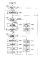
図1は、本発明の第1の実施形態を適用したノイズ除去システムを有する内視鏡システムの内部構成を概略的に示すブロック図である。
Embodiments of the present invention will be described below with reference to the drawings.
FIG. 1 is a block diagram schematically showing an internal configuration of an endoscope system having a noise removal system to which the first embodiment of the present invention is applied.
内視鏡システム10は、内視鏡プロセッサ20、電子内視鏡30、およびモニタ11によって構成される。内視鏡プロセッサ10は、電子内視鏡20、及びモニタ11に接続される。
The
内視鏡プロセッサ20から被写体に照射するための照明光が電子内視鏡30に供給される。照明光を照射された被写体が電子内視鏡30により撮像される。電子内視鏡30の撮像により生成する画像信号が内視鏡プロセッサ20に送られる。
Illumination light for irradiating the subject from the
内視鏡プロセッサ20では、電子内視鏡30から得られた画像信号に対して所定の信号処理が施される。所定の信号処理を施した画像信号はモニタ11に送信され、送信された画像信号に相当する画像がモニタ11に表示される。
In the
内視鏡プロセッサ20には光源ユニット40、画像信号処理ユニット50、撮像素子駆動回路21、システムコントローラ22、および入力部23などが設けられる。
The
後述するように、光源ユニット40は被写体に照射する照明光をライトガイド31の入射端に向かって発光する。また、後述するように、画像信号処理ユニット50では画像信号に対して所定の信号処理が施される。撮像素子駆動回路21により、撮像素子32は被写体像を撮像するように駆動される。システムコントローラ22により内視鏡システム10の動作が制御される。使用者が入力部23への操作入力を行なうことにより、内視鏡システム10の様々な機能が実行される。
As will be described later, the
内視鏡プロセッサ20と電子内視鏡30とを接続すると、光源ユニット40と電子内視鏡30に設けられるライトガイド31とが光学的に接続される。また、内視鏡プロセッサ20と電子内視鏡30とを接続すると、画像信号処理ユニット50および撮像素子駆動回路21と電子内視鏡30に設けられる撮像素子32とが電気的に接続される。
When the
図2に示すように、光源ユニット40は、ランプ41、絞り42、ロータリーシャッタ43、集光レンズ44、電源回路45、絞り駆動機構46、モータ47、絞り駆動回路48、およびロータリーシャッタ駆動回路49などによって構成される。
As shown in FIG. 2, the
ランプ41は、例えばキセノンランプやハロゲンランプであり、白色光を出射する。ランプ41から出射される白色光をライトガイド31の入射端に導くための光路中に絞り42、ロータリーシャッタ43、および集光レンズ44が設けられる。
The
絞り42により、ライトガイド31に入射する白色光の光量が制御される。なお、絞り42は絞り駆動機構46により駆動される。絞り駆動機構46による絞り42の駆動は、絞り駆動回路48により制御される。撮像素子32における受光量が、システムコントローラ22を介して絞り駆動回路48に伝達される。伝達された受光量に基づいて、絞り駆動回路48は絞り42の開口率を調整する。また、調整した絞り開口率はシステムコントローラ22に伝達される。
The amount of white light incident on the
ロータリーシャッタ43は円板上に開口部と遮光部とが設けられる。光源ユニット40から白色光を発光するときには、光路上に開口部が挿入される。一方、白色光の発光を停止するときには、光路上に遮光部が挿入され、遮光される。
The
モータ47を回転させることにより光源ユニット40からの白色光の発光と発光停止とが切替えられ、パルス発光状態となる。また、光路上に開口部を挿入したままモータ47を停止することにより白色光が光源ユニット40から発光されたまま維持され、定常発光状態となる。一方、光路上に遮光部を挿入したままモータ47を停止することにより、白色光の光源ユニット40からの発光停止状態となる。
By rotating the
なお、モータ47は、ロータリーシャッタ駆動回路49により駆動される。また、ロータリーシャッタ駆動回路49は、システムコントローラ22に制御される。
The
集光レンズ44により、光源ユニット40から発光される白色光が集光され、ライトガイド31の入射端に入射する。
The condensing
ランプ41には、電源回路45から電力が供給される。電源回路45からのランプ41への電力の供給のON/OFFは、システムコントローラ22により制御される。
Electric power is supplied to the
次に電子内視鏡30の構成について詳細に説明する(図1参照)。電子内視鏡30には、ライトガイド31、撮像素子32、配光レンズ33、および対物レンズ34などが設けられる。ライトガイド31は、内視鏡プロセッサ20との接続部分から電子内視鏡30の挿入管35の先端まで延設される。
Next, the configuration of the
前述のように光源ユニット40から出射される白色光がライトガイド31の入射端に入射される。入射端に入射された光は、出射端まで伝達される。ライトガイド31の出射端から出射する光が、配光レンズ33を介して挿入管35先端付近に照射される。
As described above, the white light emitted from the
白色光が照射されたときの被写体の反射光による光学像が、対物レンズ34を介して撮像素子32の受光面に到達する。撮像素子32には、撮像素子駆動回路21から撮像素子駆動信号が送信される。撮像素子駆動信号に基づいて、撮像素子32は撮像を行い、画像信号を生成する。なお、撮像素子駆動回路21は、システムコントローラ22により制御される。
The optical image of the reflected light of the subject when irradiated with white light reaches the light receiving surface of the
撮像素子32はCMOS撮像素子であり、受光面にはマトリックス状に画素(図示せず)が配置される。画素はフォトダイオードを有しており、各画素の受光量に応じた信号電荷が生成される。生成した信号電荷が画素信号として読出される。受光面を構成する複数の画素から読出される画素信号により画像信号が形成される。すなわち、信号電荷は画像信号に変換される。
The
グローバル露光方法では、全画素において同時期に信号電荷を生成させ、画素信号を順番に読出させることにより、撮像素子32は光学像を撮像する。一方、ライン露光方法では、行毎に信号電荷を生成させ、画素信号を順番に読み出させることにより、撮像素子32は光学像を撮像する。システムコントローラ22の制御に基づいて、撮像素子駆動回路21は、ライン露光またはグローバル露光による撮像を撮像素子32に実行させる。
In the global exposure method, the
グローバル露光により撮像を行うとき、被写体の光学像に相当する画像信号である通常画像信号を生成させる前に、通常画像信号に含まれる固定パターンノイズを除去するための黒色画像信号を撮像素子32に生成させる。なお、黒色画像信号は、光を受光面に入射させない状況において生成した画像信号である。ライン露光により撮像を行うときには、通常画像信号のみを、撮像素子32に生成させる。
When imaging with global exposure, before generating a normal image signal that is an image signal corresponding to an optical image of a subject, a black image signal for removing fixed pattern noise included in the normal image signal is supplied to the
なお、黒色画像信号は、グローバル露光による撮像時だけでなく、電子内視鏡30の初期化を行うときにも、生成される。電子内視鏡30を初期化する操作入力が入力部23に検出されると、撮像素子制御回路21は撮像素子32に黒色画像信号を生成させる。
Note that the black image signal is generated not only at the time of imaging by global exposure but also when the
黒色画像信号を生成させるために、1フィールド期間または1フレーム期間中に光源ユニット40からの白色光の発光を停止させるように、システムコントローラ22はロータリーシャッタ駆動回路49を制御する。このときに撮像素子32が生成する画像信号をシステムコントローラ22は黒色画像信号として認識し、以後の処理において通常画像信号と区別する。
In order to generate the black image signal, the
生成した黒色画像信号および通常画像信号は、画像信号処理ユニット50に送信される。図3に示すように、画像信号処理ユニット50は、A/Dコンバータ51、フレームメモリ52、第1、第2の輝度検出回路53a、53b、判別回路54、カウンタ55、演算回路56、乗算器57、および後段信号処理回路58によって構成される。
The generated black image signal and normal image signal are transmitted to the image
画像信号処理ユニット50に入力された黒色画像信号および通常画像信号は、A/Dコンバータ51においてアナログ信号からデジタル信号に変換される。
The black image signal and the normal image signal input to the image
A/D変換された黒色画像信号はフレームメモリ52に送信され、格納される。フレームメモリ52は、乗算器57を介して演算回路56に接続される。フレームメモリ52に格納された黒色画像信号は乗算器57により、システムコントローラ22が定めるゲインに基づいて増幅される。
The A / D converted black image signal is transmitted to the
なお、システムコントローラ22は絞り42の開口率が大きくなるほどゲインが小さくなるように定め、開口率が小さくなるほどゲインが大きくなるように定める。なお、ゲインを大きくするほど、後述するノイズ除去の効果が大きくなるが、ゲインを大きくしすぎると、逆にノイズ除去の精度が低下する。増幅された黒色画像信号は、演算回路56に送信される。
The
A/D変換された通常画像信号は、演算回路56に送信される。演算回路56において、通常画像信号から増幅された黒色画像信号を減算することにより、通常画像信号に含まれる固定パターンノイズが除去される。
The A / D converted normal image signal is transmitted to the
なお、A/D変換された黒色画像信号は、フレームメモリ52だけでなく、第1の輝度算出回路53aにも送信される。第1の輝度算出回路53aにより、黒色画像信号に相当する画像の平均輝度が検出される。検出された平均輝度は、判別回路54に通知される。
The A / D converted black image signal is transmitted not only to the
判別回路54では、平均輝度が輝度閾値を超えるか否かを判別する。黒色画像信号は画像信号を生成するときに発生する固定パターンノイズであり、平均輝度はゼロレベルに近い。輝度閾値は固定パターンノイズとして想定される輝度レベルを超える値に定められる。したがって、平均輝度が輝度閾値を超える場合は、撮像素子32に光が入射している状態と推測できる。判別結果がシステムコントローラ22に通知される。
The
平均輝度が輝度閾値未満である場合、システムコントローラ22はロータリーシャッタ駆動回路49および撮像素子駆動回路32を制御して、通常画像信号を生成させる。さらに、生成した通常画像信号から黒色画像信号を減算するように、演算回路56を制御する。
When the average brightness is less than the brightness threshold, the
一方、平均輝度が輝度閾値を超える場合、システムコントローラ22はロータリーシャッタ駆動回路49および撮像素子駆動回路32を制御して、黒色画像信号を生成させる。すなわち、再び1フィールド期間または1フレーム期間中の光源ユニット40からの発光を禁止して、黒色画像信号を生成させる。さらに、再度生成させた黒色画像信号の平均輝度と輝度閾値とが、判別回路54によって比較される。
On the other hand, when the average luminance exceeds the luminance threshold, the
判別回路54はカウンタ55にも接続されており、判別結果はカウンタ55にも通知される。カウンタ55により、平均輝度が輝度閾値を連続して超える回数である繰返し回数が数えられる。なお、平均輝度が輝度閾値未満となったときには、繰返し回数がゼロにリセットされる。繰返し回数は、システムコントローラ22に通知される。
The
平均輝度が輝度閾値未満となるまで、またはカウンタ55により数えられた繰返し回数が回数閾値を超えるまで、システムコントローラ22は黒色画像信号を生成させる。
The
繰返し回数が回数閾値を超えたときには、システムコントローラ22はロータリーシャッタ駆動回路49および撮像素子駆動回路32を制御して、通常光画像信号を生成させる。さらに、生成した通常画像信号から黒色画像信号の減算を行なわせずに、演算回路56から出力させる。
When the number of repetitions exceeds the number threshold, the
演算回路56は、後段信号処理回路58および第2の輝度検出回路53bに接続される。演算回路56から出力される通常画像信号は後段信号処理回路58および第2の輝度検出回路53bに送信される。
The
後段信号処理回路58では、ゲインコントロール、ホワイトバランス、色補間処理、などの所定の信号処理が施される。また、後段信号処理回路58は、繰返し回数が回数閾値未満である場合における黒色画像信号の生成を繰り返しているときに、スコープ先端を遮光するように指示する警告を通常画像信号に相当する画像にスーパーインポーズさせる。また、繰返し回数が回数閾値を超えるときには、ノイズ除去ができないことを示す警告を通常光画像信号に相当する画像にスーパーインポーズさせる。
The post-stage
後段信号処理回路58から通常画像信号は、モニタ11に送信される。モニタ11には、送信された通常画像信号に対応する画像が表示される。
The normal image signal is transmitted from the post-stage
第2の輝度検出回路53bにより、通常画像信号に相当する画像の平均輝度が検出される。前述のように、検出された平均輝度は、システムコントローラ22を介して絞り駆動回路48に通知される。
The second
内視鏡システム10には通常画像観察モードと声帯を観察するための声帯観察モードが設けられる。使用者が通常観察モードを選択する場合には、光源ユニット40は白色光を常時発光し、撮像素子32はライン露光方法により被写体を撮像する。一方、使用者が声帯観察モードを選択する場合には、光源ユニット40はパルス発光し、露光方法がグローバル露光方法に切替えられる。
The
次に、内視鏡システム10起動後に、被写体を撮像して、モニタ11に表示させるために内視鏡プロセッサ20の各部位によって行なわれる動作を、図4、図5のフローチャートを用いて説明する。なお、本処理は内視鏡プロセッサ20の電源がOFFに切替えられるときに、終了する。図4は、被写体の撮像およびモニタへの表示のために内視鏡プロセッサの各部位によって実行される動作を示すフローチャートである。図5は、黒色画像信号生成のサブルーチンを説明するためのフローチャートである。
Next, an operation performed by each part of the
ステップS100では、入力部23が初期化するための操作入力を検出しているか否かをシステムコントローラ22が判別する。操作入力を検出するときはサブルーチンS200に進む。操作入力を検出しないときはサブルーチンS200をスキップして、ステップS101に進む。
In step S100, the
サブルーチンS200は黒色画像信号生成のサブルーチンであって、後述するように撮像素子駆動回路21は黒色画像信号を生成させ、システムコントローラ22は黒色画像信号をフレームメモリ52に格納させる。
Subroutine S200 is a subroutine for generating a black image signal. As will be described later, imaging
ステップS101では、通常画像観察モードか声帯観察モードのいずれのモードが選択されているかをシステムコントローラ22が判別する。なお、モードは使用者による入力部23への操作入力によって切替え可能である。
In step S101, the
通常画像観察モードが選択されている場合、ステップS102に進む。ステップS102では、システムコントローラ22は光源ユニット40に白色光を定常発光させる。次のステップS103において、撮像素子駆動回路21は撮像素子32に通常画像信号を生成させる。生成された通常画像信号に画像信号処理ユニット50が所定の信号処理を施してモニタ11に送信する。モニタ11への送信後にステップS101に戻る。
If the normal image observation mode is selected, the process proceeds to step S102. In step S102, the
ステップS101において声帯観察モードが選択されている場合、ステップS104に進む。ステップS104では、システムコントローラ22が光源ユニット40に白色光をパルス発光させる。また、撮像素子駆動回路21が撮像素子32にグローバル露光による撮像を実行させる。
If the vocal cord observation mode is selected in step S101, the process proceeds to step S104. In step S104, the
グローバル露光に切替えた後のステップS105において、黒色画像信号がフレームメモリ52に格納されているか否かをシステムコントローラ22が判別する。黒色画像信号が格納されていない場合は、サブルーチンS200に戻り、黒色画像信号の生成のサブルーチンS200を実行する。黒色画像信号が格納されている場合は、ステップS106に進む。
In step S105 after switching to the global exposure, the
ステップS106では、サブルーチンS200の処理によって検出した黒色画像信号に相当する画像の平均輝度が輝度閾値未満であるか否かを判別する。平均輝度が輝度閾値未満である場合は、ステップS107に進む。平均輝度が輝度閾値を超える場合は、ステップS111に進む。 In step S106, it is determined whether or not the average luminance of the image corresponding to the black image signal detected by the processing of subroutine S200 is less than the luminance threshold. If the average luminance is less than the luminance threshold, the process proceeds to step S107. If the average luminance exceeds the luminance threshold, the process proceeds to step S111.
ステップS107では、撮像素子駆動回路21は撮像素子32に、通常画像信号を生成させる。通常画像信号を生成させると、ステップS108に進む。ステップS108では、第2の輝度検出回路53bは通常画像信号に相当する画像の平均輝度を検出する。平均輝度の検出後にステップS109に進む。平均輝度に基づいて絞り駆動回路48は絞り42の開口率を決定し、決定された開口率に基づいてシステムコントローラ22は黒色画像信号に乗じるゲインを決定する。
In step S107, the image
次のステップS110において、乗算器57は決定したゲインをフレームメモリ52に格納した黒色画像信号に乗じる。さらに、通常画像信号からゲインが乗じられた黒色画像信号を減じることにより、演算回路56は固定パターンノイズを除去する。固定パターンノイズを除去した通常画像信号に画像信号処理ユニット50が所定の信号処理を施してモニタ11に送信する。以後、ステップS101に戻る。
In the next step S110, the
前述のように、ステップS106において平均輝度が輝度閾値を超える場合に、ステップS111に進む。ステップS111では、後段信号処理回路58が、例えば、“ノイズを除去するための画像信号が取得できません”などのようにノイズ除去が不可能であることを示す警告を、通常画像信号に相当する画像にスーパーインポーズする。
As described above, when the average luminance exceeds the luminance threshold value in step S106, the process proceeds to step S111. In step S111, the post-stage
次のステップS112では、撮像素子駆動回路21が撮像素子32を駆動して、通常画像信号を生成させる。通常画像信号を生成させると、ステップS113に進む。ステップS113では、通常画像信号のノイズ除去を停止する。すなわち、演算回路56における通常画像信号から黒色画像信号の減算を停止させる。ノイズが除去されなかった通常画像信号に画像信号処理ユニット50が所定の信号処理を施してモニタ11に送信する。以後、ステップS101に戻る。
In the next step S112, the image
次に、黒色画像信号生成のサブルーチンS200について説明する。ステップS201において、システムコントローラ22は、1フィールド期間または1フレーム期間内における信号電荷を生成させるための受光時に、光源ユニット40からの白色光の発光を禁止する。したがって、光源ユニット40は発光停止する。
Next, the black image signal generation subroutine S200 will be described. In step S201, the
白色光の発光を停止すると、ステップS202において、撮像素子駆動回路21は撮像素子32に、白色光の発光停止期間中に生成した信号電荷に基づく画像信号を黒色画像信号として生成させる。フレームメモリ52は生成した黒色画像信号を格納する。黒色画像信号を格納すると、ステップS203に進み、第1の輝度検出回路53aは黒色画像信号に相当する画像の平均輝度を検出する。
When the white light emission is stopped, in step S202, the image
平均輝度を検出すると、ステップS204において、判別回路54は平均輝度が輝度閾値未満であるか否かを判別する。平均輝度が輝度閾値未満である場合には、以後のステップS205、ステップS206をスキップして、黒色画像信号生成のサブルーチンS200を終了する。平均輝度が輝度閾値を超える場合には、ステップS205に進む。
When the average luminance is detected, in step S204, the
ステップS205では、カウンタ55が繰返し回数に1を加算する。次のステップS206において、システムコントローラ22は繰返し回数が回数閾値未満であるか否かを判別する。
In step S205, the
繰返し回数が回数閾値未満である場合は、ステップS207に進む。ステップS207では、後段信号処理回路58が、例えば、“スコープ先端に光があたらないようにして下さい”などのように挿入管35の先端の遮光を指示する警告を、通常画像信号に相当する画像にスーパーインポーズする。繰返し回数が回数閾値を超える場合には、黒色画像信号生成のサブルーチンS200を終了する。
If the number of repetitions is less than the number threshold, the process proceeds to step S207. In step S207, the post-stage
以上のような第1の実施形態のノイズ除去システムによれば、CMOS撮像素子にグローバル露光方法によって被写体の撮像を行わせるときに、黒色画像信号を生成させ、黒色画像信号を用いて、固定パターンノイズを除去することが可能になる。CMOS撮像素子のグローバル露光方法による画像信号には、ライン露光方法による画像信号に比べて、より大きな固定パターンノイズが混入する。しかし、より大きな固定パターンノイズはノイズ除去システムにより効果的に除去される。 According to the noise removal system of the first embodiment as described above, a black image signal is generated and a fixed pattern is generated using a black image signal when the CMOS image sensor performs imaging of a subject by the global exposure method. Noise can be removed. Larger fixed pattern noise is mixed in the image signal by the global exposure method of the CMOS image sensor than the image signal by the line exposure method. However, larger fixed pattern noise is effectively removed by the noise removal system.
また、第1の実施形態のノイズ除去システムによれば、実際の診察前に電子内視鏡を初期化するときに、黒色画像信号を生成させることが可能である。グローバル露光方法に切替えるときに黒色画像信号を生成させる場合には、少なくとも1フィールド期間モニタ11に画像が表示されない。しかし、本実施形態では初期化時に黒色画像信号を生成させるので、このような問題が解消される。
Further, according to the noise removal system of the first embodiment, it is possible to generate a black image signal when initializing the electronic endoscope before the actual examination. When a black image signal is generated when switching to the global exposure method, an image is not displayed on the
次に、本発明の第2の実施形態を適用したノイズ除去システムについて説明する。第2の実施形態は、黒色画像信号の生成方法が第1の実施形態と異なっている。第1の実施形態では、1フィールド期間または1フレーム期間中に光源ユニット40からの白色光の発光を停止させることにより黒色画像信号が生成される。第2の実施形態では、光源ユニット40からの白色光の発光停止中に信号電荷の生成を行なわせる。以下、第1の実施形態と異なる部位を中心に説明する。
Next, a noise removal system to which the second embodiment of the present invention is applied will be described. The second embodiment is different from the first embodiment in the method for generating a black image signal. In the first embodiment, a black image signal is generated by stopping the emission of white light from the
光源ユニット40の構成および機能は、第1の実施形態と同じである。したがって、システムコントローラ22の制御により、光源ユニット40からの白色光のパルス発光、定常発光、および発光停止が切替えられる。
The configuration and function of the
電子内視鏡30の構成および機能は、第1の実施形態と同じである。したがって、システムコントローラ22の制御に基づいて撮像素子駆動回路21が撮像素子32を駆動して、ライン露光方法またはグローバル露光方法によって被写体が撮像される。
The configuration and function of the
なお、第1の実施形態では、黒色画像信号を生成するときに、撮像素子32は通常画像信号を生成するときと同じ駆動方法で駆動され、光源ユニット40の駆動方法が通常画像信号を生成するときの駆動方法と異なっている。図6に示すように、第1の実施形態では、黒色画像信号を生成するフィールド期間中のパルス発光が停止される。前述のように、このフィールド期間に出力される画像信号が黒色画像信号として用いられる。また、以後のフィールド期間に出力される画像信号が通常画像信号として用いられる。
In the first embodiment, when the black image signal is generated, the
一方、第2の実施形態では、黒色画像信号を生成するときに、光源ユニット40は通常画像信号を生成するときと同じ駆動方法で駆動され、撮像素子32の駆動方法が通常画像信号を生成するときの駆動方法と異なっている。図7に示すように、第2の実施形態では、パルス発光における発光停止中に、信号電荷を生成させるように撮像素子32が駆動される(黒色画像信号出力参照)。なお、黒色画像信号の出力後は、第1の実施形態と同様に通常画像信号が出力される。
On the other hand, in the second embodiment, when generating the black image signal, the
画像信号処理ユニット50の構成および機能は、第1の実施形態と同じである。したがって、システムコントローラ22の制御により通常画像信号から固定パターンノイズが除去される。
The configuration and function of the image
第1の実施形態と同様に、第2の実施形態における内視鏡システム10にも、声帯観察モードが設けられる。使用者が声帯観察モードを選択する場合に、光源ユニット40はパルス発光を行ない、露光方法がグローバル露光方法に切替えられる。
Similar to the first embodiment, the
また、第1の実施形態と同様に、第2の実施形態における内視鏡システム10においても、黒色画像信号はグローバル露光による撮像時だけでなく、電子内視鏡30の初期化を行うときにも、生成される。
Similarly to the first embodiment, in the
次に、第2の実施形態における内視鏡システム10起動後に、被写体を撮像して、モニタ11に表示させるために内視鏡プロセッサ20の各部位によって行なわれる動作を、図8、図9のフローチャートを用いて説明する。なお、本処理は内視鏡プロセッサ20の電源がOFFに切替えられるときに、終了する。図8は、被写体の撮像およびモニタへの表示のために内視鏡プロセッサの各部位によって実行される動作を示すフローチャートである。図9は、黒色画像信号生成のサブルーチンを説明するためのフローチャートである。
Next, after the activation of the
ステップS300では、入力部23が初期化するための操作入力を検出しているか否かをシステムコントローラ22が判別する。操作入力を検出するときはサブルーチンS400に進む。操作入力を検出しないときはサブルーチンS400をスキップして、ステップS301に進む。
In step S300, the
サブルーチンS400は黒色画像信号生成のサブルーチンであって、後述するように撮像素子駆動回路21は黒色画像信号を生成させ、システムコントローラ22は黒色画像信号をフレームメモリ52に格納させる。
Subroutine S400 is a subroutine for generating a black image signal. As will be described later, the image
ステップS301では、通常画像観察モードか声帯観察モードのいずれのモードが選択されているかをシステムコントローラ22が判別する。なお、モードは使用者による入力部23への操作入力によって切替え可能である。
In step S301, the
通常画像観察モードが選択されている場合、ステップS302に進む。ステップS302では、システムコントローラ22は光源ユニット40に白色光を定常発光させる。次のステップS303において、撮像素子駆動回路21は撮像素子32に通常画像信号を生成させる。生成された通常画像信号に画像信号処理ユニット50が所定の信号処理を施してモニタ11に送信する。モニタ11への送信後にステップS301に戻る。
If the normal image observation mode is selected, the process proceeds to step S302. In step S302, the
ステップS301において声帯観察モードが選択されている場合、ステップS304に進む。ステップS304では、撮像素子駆動回路21が撮像素子32にグローバル露光による撮像を実行させる。また、パルス発光期間中、すなわち発光と発光停止とが交互に繰返される期間中に信号電荷を生成させるように、撮像素子駆動回路21は撮像素子32を駆動する。なお、後述するようにサブルーチンS400において、光源ユニット40は白色光をパルス発光するように駆動状態を切替えられている。
If the vocal cord observation mode is selected in step S301, the process proceeds to step S304. In step S304, the image
ステップS305では、黒色画像信号がフレームメモリ52に格納されているか否かをシステムコントローラ22が判別する。黒色画像信号が格納されていない場合は、サブルーチンS400に戻り、黒色画像信号の生成のサブルーチンS200を実行する。黒色画像信号が格納されている場合は、ステップS306に進む。
In step S <b> 305, the
ステップS306では、サブルーチンS400の処理によって検出した黒色画像信号に相当する画像の平均輝度が輝度閾値未満であるか否かを判別する。平均輝度が輝度閾値未満である場合は、ステップS307に進む。平均輝度が輝度閾値を超える場合は、ステップS311に進む。 In step S306, it is determined whether or not the average luminance of the image corresponding to the black image signal detected by the process of subroutine S400 is less than the luminance threshold. If the average luminance is less than the luminance threshold, the process proceeds to step S307. If the average luminance exceeds the luminance threshold, the process proceeds to step S311.
ステップS307では、撮像素子駆動回路21は撮像素子32に、ステップS205で生成した信号電荷に基づく画像信号を、通常画像信号として生成させる。通常画像信号を生成させると、ステップS308に進む。ステップS308では、第2の輝度検出回路53bは通常画像信号に相当する画像の平均輝度を検出する。平均輝度の検出後にステップS309に進む。平均輝度に基づいて絞り駆動回路48は絞り42の開口率を決定し、決定された開口率に基づいてシステムコントローラ22は黒色画像信号に乗じるゲインを決定する。
In step S307, the image
次のステップS310において、乗算器57は決定したゲインをフレームメモリ52に格納した黒色画像信号に乗じる。さらに、通常画像信号からゲインが乗じられた黒色画像信号を減じることにより、演算回路56は固定パターンノイズを除去する。固定パターンノイズを除去した通常画像信号に画像信号処理ユニット50が所定の信号処理を施してモニタ11に送信する。以後、ステップS301に戻る。
In the next step S310, the
前述のように、ステップS306において平均輝度が輝度閾値を超える場合に、ステップS311に進む。ステップS311では、後段信号処理回路58が、例えば、“ノイズを除去するための画像信号が取得できません”などのようにノイズ除去が不可能であることを示す警告を、通常画像信号に相当する画像にスーパーインポーズする。
As described above, when the average luminance exceeds the luminance threshold value in step S306, the process proceeds to step S311. In step S311, the post-stage
次のステップS312では、撮像素子駆動回路21は撮像素子32に、ステップS205で生成した信号電荷に基づく画像信号を、通常画像信号として生成させる。通常画像信号を生成させると、ステップS313に進む。ステップS313では、通常画像信号のノイズ除去を停止する。すなわち、演算回路56における通常画像信号から黒色画像信号の減算を停止させる。ノイズが除去されなかった通常画像信号に画像信号処理ユニット50が所定の信号処理を施してモニタ11に送信する。以後、ステップS101に戻る。
In the next step S312, the image
次に、黒色画像信号生成のサブルーチンS400について説明する。ステップS401において、システムコントローラ22は光源ユニット40にパルス発光を開始させる。パルス発光を開始すると、ステップS402に進み、撮像素子駆動回路21は撮像素子32を駆動して、パルス発光における発光停止期間中に信号電荷を生成させる。
Next, the black image signal generation subroutine S400 will be described. In step S401, the
ステップS403では、撮像素子駆動回路21は撮像素子32に、ステップS201において生成させた信号電荷に基づく画像信号を、黒色画像信号として生成させる。フレームメモリ52は生成した黒色画像信号を格納する。黒色画像信号を格納すると、ステップS404に進み、第1の輝度検出回路53aは黒色画像信号に相当する画像の平均輝度を検出する。
In step S403, the image
平均輝度を検出すると、ステップS405において、判別回路54は平均輝度が輝度閾値未満であるか否かを判別する。平均輝度が輝度閾値未満である場合には、以後のステップS406、ステップS407をスキップして、黒色画像信号生成のサブルーチンS400を終了する。平均輝度が輝度閾値を超える場合には、ステップS406に進む。
When the average luminance is detected, in step S405, the
ステップS406では、カウンタ55が繰返し回数に1を加算する。次のステップS407において、システムコントローラ22は繰返し回数が回数閾値未満であるか否かを判別する。
In step S406, the
繰返し回数が回数閾値未満である場合は、ステップS408に進む。ステップS408では、後段信号処理回路58が、例えば、“スコープ先端に光があたらないようにして下さい”などのように挿入管35の先端の遮光を指示する警告を、通常画像信号に相当する画像にスーパーインポーズする。繰返し回数が回数閾値を超える場合には、黒色画像信号生成のサブルーチンS400を終了する。
If the number of repetitions is less than the number threshold, the process proceeds to step S408. In step S408, the post-stage
以上のような第2の実施形態のノイズ除去システムによっても、CMOS撮像素子にグローバル露光方法によって被写体の撮像を行わせるときに、黒色画像信号を生成させ、黒色画像信号を用いて、固定パターンノイズを除去することが可能になる。 Even with the noise elimination system of the second embodiment as described above, when the CMOS image sensor performs imaging of a subject by the global exposure method, a black image signal is generated and fixed pattern noise is generated using the black image signal. Can be removed.
また、第2の実施形態のノイズ除去システムによっても、実際の診察前に電子内視鏡を初期化するときに、黒色画像信号を生成させることが可能である。 The noise removal system of the second embodiment can also generate a black image signal when initializing the electronic endoscope before the actual examination.
なお、第1、第2の実施形態では、検出した黒色画像信号の平均輝度が輝度閾値を超える場合に、再度黒色画像信号を生成させ、フレームメモリ52に格納させる構成であるが、再度の黒色画像信号の生成およびフレームメモリ52への格納を繰返さなくてもよい。
In the first and second embodiments, when the average luminance of the detected black image signal exceeds the luminance threshold, the black image signal is generated again and stored in the
黒色画像信号が輝度閾値を超える場合、撮像素子32に光が入射していると推測される。光の入射しない領域においてグローバル露光を開始すれば、誤作動がない限り黒色画像信号が輝度閾値を超えることは無いため、上述のような黒色画像信号の再生成は不要である。
When the black image signal exceeds the luminance threshold, it is estimated that light is incident on the
また、第1、第2の実施形態では、電子内視鏡30を初期化するときに、黒色画像信号が生成され、フレームメモリ52に格納される構成であるが、初期化時には黒色画像信号が生成されない構成であってもよい。前述のように、黒色画像信号はグローバル露光時に特に必要となるため、グローバル露光への切替え時に生成されればよい。ただし、第1、第2の実施形態のように、初期化時に生成され、格納されることにより使用者の操作性が向上する。
In the first and second embodiments, a black image signal is generated and stored in the
また、第1、第2の実施形態では、検出した黒色画像信号の平均輝度が輝度閾値を超える場合に、内視鏡先端に光が照射されていることを示す警告がモニタ11表示される構成であるが、警告が表示されなくてもよい。前述のように、光の入射しない領域においてグローバル露光を開始すれば、誤作動がない限り黒色画像信号が輝度閾値を超えることは無く、上述のような警告表示機能は不要である。
In the first and second embodiments, when the average luminance of the detected black image signal exceeds the luminance threshold, a warning indicating that light is irradiated on the distal end of the endoscope is displayed on the
また、第1、第2の実施形態では、黒色画像信号の平均輝度が輝度閾値を超える回数が回数閾値を超える場合に、ノイズ除去不可の警告がモニタ11に表示され、固定パターンノイズの除去を停止する構成であるが、警告が表示されなくてもよいし、ノイズ除去を停止しなくてもよい。前述のように、光の入射しない領域においてグローバル露光を開始すれば、誤作動がない限り黒色画像信号が輝度閾値を超えることは無く、上述のような警告表示機能およびノイズ除去停止機能は不要である。
In the first and second embodiments, when the number of times that the average luminance of the black image signal exceeds the luminance threshold exceeds the frequency threshold, a warning indicating that noise cannot be removed is displayed on the
また、第1、第2の実施形態では、黒色画像信号にゲインを乗じる構成であるが、乗ずること無く、通常画像信号から黒色画像信号を減じてもよい。ゲインを乗じることによりノイズの除去効果が大きくなるが、ゲインを乗じなくてもノイズ除去可能だからである。 In the first and second embodiments, the black image signal is multiplied by the gain. However, the black image signal may be subtracted from the normal image signal without multiplication. This is because the noise removal effect is increased by multiplying the gain, but the noise can be removed without multiplying the gain.
また、第1、第2の実施形態では、絞り42の開口率に応じてゲインを調整する構成であるが、他の方法によりゲインが調整されてもよい。例えば、使用者による入力部23への入力により調整されてもよいし、通常画像信号に相当する画像の輝度に基づいて調整されてもよいし、さらには、ノイズ除去後の通常画像信号にまだ含まれるノイズ量に基づいてゲインを調整してもよい。あるいは、固定されたゲインを黒色画像信号に乗じる構成であってもよい。
In the first and second embodiments, the gain is adjusted according to the aperture ratio of the
また、第1の実施形態では、1フィールド期間中、光源ユニット40を発光停止にさせる構成であるが、1フィールドの前期間中発光停止する必要は無い。1フィールド期間または1フレーム期間における画像信号に変換される信号電荷生成のための受光期間中(図6符号P1参照)に発光停止させれば、第1の実施形態と同じ効果を得ることが可能である。
In the first embodiment, the
また、第1の実施形態では、光源ユニット40にパルス発光させる構成であるが、パルス発光させなくてもよい。黒色画像信号として画像信号を生成するフィールド期間またはフレーム期間中に光源ユニット40を発光停止にすれば、第1の実施形態と同じ効果を得ることが可能である。
Further, in the first embodiment, the
また、第2の実施形態では、1フィールド期間に複数パルスの発光が行われるが、1フィールド期間に少なくとも1パルスの発光が行われてもよい。例えば、図10に示すように、1フィールド期間毎の1パルス発光が、フィールド信号の切替わり直後に行なわれる。黒色画像信号を出力するためにパルス発光終了後から読出し開始までの間、信号電荷が生成される(黒色画像信号出力時のフィールド期間参照)。 In the second embodiment, light emission of a plurality of pulses is performed in one field period, but light emission of at least one pulse may be performed in one field period. For example, as shown in FIG. 10, one-pulse light emission for each field period is performed immediately after the field signal is switched. In order to output a black image signal, signal charges are generated after the end of pulse emission until the start of reading (see the field period when the black image signal is output).
固定パターンノイズ除去のためには、黒色画像信号生成のための信号電荷生成期間は通常画像信号生成のための信号電荷生成期間に近いことが望ましい。それゆえ、フィールド切替わり直後に1パルスの発光のみを行なわせ、信号電荷生成期間を長くすることによりノイズ除去の精度が向上する。 In order to remove fixed pattern noise, it is desirable that the signal charge generation period for black image signal generation is close to the signal charge generation period for normal image signal generation. Therefore, only one pulse is emitted immediately after the field switching, and the signal charge generation period is lengthened to improve the noise removal accuracy.
10 内視鏡システム
20 内視鏡プロセッサ
21 撮像素子駆動回路
22 システムコントローラ
30 電子内視鏡
32 撮像素子
40 光源ユニット
49 ロータリーシャッタ駆動回路
50 画像信号処理ユニット
52 フレームメモリ
53a、53b 第1、第2の輝度検出部
54 判別回路
55 カウンタ
56 演算回路
57 乗算器
58 後段信号処理回路
DESCRIPTION OF
Claims (17)
前記露光方法が前記グローバル露光に切替えられた後の少なくとも1フィールド期間または1フレーム期間内において、前記画像信号に変換される前記信号電荷を生成するための受光期間中に、前記被写体を照明するための照明光の前記被写体への照射を停止させる光源制御部と、
前記照明光の前記被写体への照射が停止されている間に生成した信号電荷に基づく前記画像信号を黒色画像信号として格納するメモリと、
前記メモリに格納された前記黒色画像信号に基づいて、前記照明光が前記被写体に照射されている間に生成した前記信号電荷に基づく前記画像信号である通常画像信号に含まれる固定パターンノイズを除去するノイズ除去部とを備える
ことを特徴とするノイズ除去システム。 An exposure changeover switch for switching the exposure method of the CMOS image sensor, which is provided in the electronic endoscope and generates an image signal corresponding to the optical image based on a signal charge generated by receiving the optical image of the subject, to global exposure;
In order to illuminate the subject during a light receiving period for generating the signal charge converted into the image signal within at least one field period or one frame period after the exposure method is switched to the global exposure. A light source control unit for stopping irradiation of the subject with the illumination light of
A memory for storing, as a black image signal, the image signal based on a signal charge generated while irradiation of the subject with the illumination light is stopped;
Based on the black image signal stored in the memory, fixed pattern noise included in a normal image signal that is the image signal based on the signal charge generated while the illumination light is irradiated on the subject is removed. The noise removal system characterized by including the noise removal part which performs.
前記初期化入力部への前記電子内視鏡の初期化実行のための操作入力を検出するときに、前記光源制御部は検出後の少なくとも1フィールド期間または1フレーム期間内において前記画像信号に変換される前記信号電荷を生成するための受光期間中に前記照明光の前記被写体への照射を停止させ、前記メモリは前記照明光の前記被写体への照射が停止されている間に生成した信号電荷に基づく前記画像信号を黒色画像信号として格納し、前記ノイズ除去部は前記メモリに格納された前記黒色画像信号に基づいて前記通常画像信号に含まれる固定パターンノイズを除去する
ことを特徴とする請求項1に記載のノイズ除去システム。 An initialization input unit for detecting an operation input for executing initialization of the electronic endoscope;
When detecting an operation input for performing initialization of the electronic endoscope to the initialization input unit, the light source control unit converts the image signal into the image signal within at least one field period or one frame period after detection. The illumination of the illumination light to the subject is stopped during the light receiving period for generating the signal charge to be generated, and the memory generates a signal charge generated while the illumination light is not illuminated to the subject. The image signal based on the image is stored as a black image signal, and the noise removing unit removes fixed pattern noise included in the normal image signal based on the black image signal stored in the memory. Item 2. The noise removal system according to Item 1.
前記光源制御部は、前記輝度算出部により算出された前記黒色画像信号の輝度が第1の閾値を超える場合に、前記画像信号に変換される前記信号電荷を生成するための受光期間中における前記照明光の照射を再び停止し、
前記メモリは、前記照明光の照射が再び停止されている間に生成した信号電荷に基づく前記黒色画像信号を格納する
ことを特徴とする請求項1または請求項2に記載のノイズ除去システム。 A luminance calculation unit for calculating the luminance of the black image signal;
The light source control unit is configured to receive the signal charge that is converted into the image signal when the luminance of the black image signal calculated by the luminance calculation unit exceeds a first threshold. Stop the illumination light again,
The noise removal system according to claim 1 or 2, wherein the memory stores the black image signal based on a signal charge generated while irradiation of the illumination light is stopped again.
前記露光方法が前記グローバル露光に切替えられた後の少なくとも1フィールド期間または1フレーム期間内において、前記照明光の前記被写体への照射が停止されている間に前記画像信号に変換される前記信号電荷を生成するための受光を前記CMOS撮像素子に実行させる撮像素子制御部と、
前記照明光の前記被写体への照射が停止されている間に生成した信号電荷に基づく前記画像信号を、黒色画像信号として格納するメモリと、
前記メモリに格納された前記黒色画像信号に基づいて、前記照明光が前記被写体に照射されている間に生成した前記信号電荷に基づく前記画像信号である通常画像信号に含まれる固定パターンノイズを除去するノイズ除去部とを備える
ことを特徴とするノイズ除去システム。 Global exposure is a CMOS image sensor exposure method that is provided in an electronic endoscope and generates an image signal corresponding to the optical image based on a signal charge generated by receiving an optical image of a subject irradiated with pulsed illumination light. An exposure changeover switch for switching to
The signal charge that is converted into the image signal while irradiation of the illumination light to the subject is stopped within at least one field period or one frame period after the exposure method is switched to the global exposure. An image sensor control unit that causes the CMOS image sensor to perform light reception for generating
A memory for storing, as a black image signal, the image signal based on a signal charge generated while irradiation of the subject with the illumination light is stopped;
Based on the black image signal stored in the memory, fixed pattern noise included in a normal image signal that is the image signal based on the signal charge generated while the illumination light is irradiated on the subject is removed. The noise removal system characterized by including the noise removal part which performs.
前記初期化入力部への前記電子内視鏡の初期化実行のための操作入力を検出するときに、前記撮像素子制御部は検出後の少なくとも1フィールド期間または1フレーム期間内において前記照明光の前記被写体への照射が停止されている間に前記画像信号に変換される前記信号電荷を生成するための受光を前記CMOS撮像素子に実行させ、前記メモリは前記照明光の前記被写体への照射が停止されている間に生成した信号電荷に基づく前記画像信号を黒色画像信号として格納し、前記ノイズ除去部は前記メモリに格納された前記黒色画像信号に基づいて前記通常画像信号に含まれる固定パターンノイズを除去する
ことを特徴とする請求項4に記載のノイズ除去システム。 An initialization input unit for detecting an operation input for executing initialization of the electronic endoscope;
When detecting an operation input for performing initialization of the electronic endoscope to the initialization input unit, the image sensor control unit detects the illumination light within at least one field period or one frame period after detection. While the irradiation of the subject is stopped, the CMOS image sensor performs light reception for generating the signal charge converted into the image signal, and the memory emits the illumination light to the subject. The image signal based on the signal charge generated while being stopped is stored as a black image signal, and the noise removing unit is a fixed pattern included in the normal image signal based on the black image signal stored in the memory The noise removal system according to claim 4, wherein noise is removed.
前記撮像素子制御部は、前記輝度算出部により算出された前記画像信号の輝度が第1の閾値を超える場合に、前記照明光の前記被写体への照射が停止されている間に前記画像信号に変換される前記信号電荷を生成するための受光を前記CMOS撮像素子に再び実行させ、
前記メモリは、前記照明光の前記被写体への照射が停止されている間に再び生成した信号電荷に基づく前記黒色画像信号を格納する
ことを特徴とする請求項4または請求項5に記載のノイズ除去システム。 A luminance calculation unit for calculating the luminance of the black image signal;
When the luminance of the image signal calculated by the luminance calculation unit exceeds a first threshold, the imaging element control unit outputs the image signal while the irradiation of the illumination light to the subject is stopped. Causing the CMOS image sensor to again perform light reception for generating the signal charge to be converted,
The noise according to claim 4 or 5, wherein the memory stores the black image signal based on a signal charge generated again while irradiation of the subject with the illumination light is stopped. Removal system.
前記露光方法が前記グローバル露光に切替えられた後の少なくとも1フィールド期間または1フレーム期間内において、前記画像信号に変換される前記信号電荷を生成するための受光期間中に、前記被写体を照明するための照明光の前記被写体への照射を停止させる光源制御部と、
前記照明光の前記被写体への照射が停止されている間に生成した信号電荷に基づく前記画像信号を黒色画像信号として格納するメモリと、
前記メモリに格納された前記黒色画像信号に基づいて、前記照明光が前記被写体に照射されている間に生成した前記信号電荷に基づく前記画像信号である通常画像信号に含まれる固定パターンノイズを除去するノイズ除去部とを備える
ことを特徴とする内視鏡プロセッサ。 An exposure changeover switch for switching the exposure method of the CMOS image sensor, which is provided in the electronic endoscope and generates an image signal corresponding to the optical image based on a signal charge generated by receiving the optical image of the subject, to global exposure;
In order to illuminate the subject during a light receiving period for generating the signal charge converted into the image signal within at least one field period or one frame period after the exposure method is switched to the global exposure. A light source control unit for stopping irradiation of the subject with the illumination light of
A memory for storing, as a black image signal, the image signal based on a signal charge generated while irradiation of the subject with the illumination light is stopped;
Based on the black image signal stored in the memory, fixed pattern noise included in a normal image signal that is the image signal based on the signal charge generated while the illumination light is irradiated on the subject is removed. An endoscope processor, comprising: a noise removing unit that performs:
前記露光方法が前記グローバル露光に切替えられた後の少なくとも1フィールド期間または1フレーム期間内において、前記照明光の前記被写体への照射が停止されている間に前記画像信号に変換される前記信号電荷を生成するための受光を前記CMOS撮像素子に実行させる撮像素子制御部と、
前記照明光の前記被写体への照射が停止されている間に生成した信号電荷に基づく前記画像信号を、黒色画像信号として格納するメモリと、
前記メモリに格納された前記黒色画像信号に基づいて、前記照明光が前記被写体に照射されている間に生成した前記信号電荷に基づく前記画像信号である通常画像信号に含まれる固定パターンノイズを除去するノイズ除去部とを備える
ことを特徴とする内視鏡プロセッサ。 Global exposure is a CMOS image sensor exposure method that is provided in an electronic endoscope and generates an image signal corresponding to the optical image based on a signal charge generated by receiving an optical image of a subject irradiated with pulsed illumination light. An exposure changeover switch for switching to
The signal charge that is converted into the image signal while irradiation of the illumination light to the subject is stopped within at least one field period or one frame period after the exposure method is switched to the global exposure. An image sensor control unit that causes the CMOS image sensor to perform light reception for generating
A memory for storing, as a black image signal, the image signal based on a signal charge generated while irradiation of the subject with the illumination light is stopped;
Based on the black image signal stored in the memory, fixed pattern noise included in a normal image signal that is the image signal based on the signal charge generated while the illumination light is irradiated on the subject is removed. An endoscope processor, comprising: a noise removing unit that performs:
前記被写体を照明するための照明光を照射する光源と、
前記CMOS撮像素子の露光方法を、グローバル露光に切替える露光切替えスイッチと、
前記露光方法が前記グローバル露光に切替えられた後の少なくとも1フィールド期間または1フレーム期間内において、前記画像信号に変換される前記信号電荷を生成するための受光期間中に、前記照明光の前記被写体への照射を停止させる光源制御部と、
前記照明光の前記被写体への照射が停止されている間に生成した信号電荷に基づく前記画像信号を、黒色画像信号として格納するメモリと、
前記メモリに格納された前記黒色画像信号に基づいて、前記照明光が前記被写体に照射されている間に生成した前記信号電荷に基づく前記画像信号である通常画像信号に含まれる固定パターンノイズを除去するノイズ除去部とを備える
ことを特徴とする内視鏡システム。 An electronic endoscope having a CMOS image sensor that generates an image signal corresponding to the optical image based on a signal charge generated by receiving an optical image of a subject;
A light source that emits illumination light for illuminating the subject;
An exposure changeover switch for switching the exposure method of the CMOS image sensor to global exposure;
The subject of the illumination light during a light receiving period for generating the signal charge converted into the image signal within at least one field period or one frame period after the exposure method is switched to the global exposure. A light source control unit for stopping irradiation to
A memory for storing, as a black image signal, the image signal based on a signal charge generated while irradiation of the subject with the illumination light is stopped;
Based on the black image signal stored in the memory, fixed pattern noise included in a normal image signal that is the image signal based on the signal charge generated while the illumination light is irradiated on the subject is removed. An endoscope system comprising: a noise removing unit that performs the above-described operation.
前記被写体に照射する照明光をパルス発光する光源と、
前記CMOS撮像素子の露光方法を、グローバル露光に切替える露光切替えスイッチと、
前記露光方法が前記グローバル露光に切替えられた後の少なくとも1フィールド期間または1フレーム期間内において、前記照明光の前記被写体への照射が停止されている間に前記画像信号に変換される前記信号電荷を生成するための受光を前記CMOS撮像素子に実行させる撮像素子制御部と、
前記照明光の前記被写体への照射が停止されている間に生成した信号電荷に基づく前記画像信号を、黒色画像信号として格納するメモリと、
前記メモリに格納された前記黒色画像信号に基づいて、前記照明光が前記被写体に照射されている間に生成した前記信号電荷に基づく前記画像信号である通常画像信号に含まれる固定パターンノイズを除去するノイズ除去部とを備える
ことを特徴とする内視鏡システム。 An electronic endoscope having a CMOS image sensor that generates an image signal corresponding to the optical image based on a signal charge generated by receiving an optical image of a subject;
A light source that emits pulses of illumination light that irradiates the subject;
An exposure changeover switch for switching the exposure method of the CMOS image sensor to global exposure;
The signal charge that is converted into the image signal while irradiation of the illumination light to the subject is stopped within at least one field period or one frame period after the exposure method is switched to the global exposure. An image sensor control unit that causes the CMOS image sensor to perform light reception for generating
A memory for storing, as a black image signal, the image signal based on a signal charge generated while irradiation of the subject with the illumination light is stopped;
Based on the black image signal stored in the memory, fixed pattern noise included in a normal image signal that is the image signal based on the signal charge generated while the illumination light is irradiated on the subject is removed. An endoscope system comprising: a noise removing unit that performs the above-described operation.
Priority Applications (4)
| Application Number | Priority Date | Filing Date | Title |
|---|---|---|---|
| JP2007315107A JP2009136459A (en) | 2007-12-05 | 2007-12-05 | Noise reduction system, endoscope processor, and endoscope system |
| US12/327,895 US20090147078A1 (en) | 2007-12-05 | 2008-12-04 | Noise reduction system, endoscope processor, and endoscope system |
| CN200810182950.5A CN101449958A (en) | 2007-12-05 | 2008-12-05 | Noise reduction system, endoscope processor, and endoscope system |
| DE102008060633A DE102008060633A1 (en) | 2007-12-05 | 2008-12-05 | Noise reduction system, endoscope processor and endoscope system |
Applications Claiming Priority (1)
| Application Number | Priority Date | Filing Date | Title |
|---|---|---|---|
| JP2007315107A JP2009136459A (en) | 2007-12-05 | 2007-12-05 | Noise reduction system, endoscope processor, and endoscope system |
Publications (1)
| Publication Number | Publication Date |
|---|---|
| JP2009136459A true JP2009136459A (en) | 2009-06-25 |
Family
ID=40690966
Family Applications (1)
| Application Number | Title | Priority Date | Filing Date |
|---|---|---|---|
| JP2007315107A Pending JP2009136459A (en) | 2007-12-05 | 2007-12-05 | Noise reduction system, endoscope processor, and endoscope system |
Country Status (4)
| Country | Link |
|---|---|
| US (1) | US20090147078A1 (en) |
| JP (1) | JP2009136459A (en) |
| CN (1) | CN101449958A (en) |
| DE (1) | DE102008060633A1 (en) |
Cited By (4)
| Publication number | Priority date | Publication date | Assignee | Title |
|---|---|---|---|---|
| JP2011030985A (en) * | 2009-08-06 | 2011-02-17 | Hoya Corp | Endoscope system and endoscope |
| JP2011114733A (en) * | 2009-11-30 | 2011-06-09 | Hoya Corp | Imaging apparatus, electronic scope, and electronic endoscope system |
| JP2012165865A (en) * | 2011-02-14 | 2012-09-06 | Olympus Corp | Endoscope apparatus, and setting method of reference image of endoscope apparatus |
| JP2016509885A (en) * | 2013-03-21 | 2016-04-04 | キム テウKIM, Tae Woo | Flat-scan video chymography system for analyzing vocal cord mucosal motion and method for analyzing vocal cord mucosal motion using the same |
Families Citing this family (15)
| Publication number | Priority date | Publication date | Assignee | Title |
|---|---|---|---|---|
| JP5244455B2 (en) * | 2008-05-21 | 2013-07-24 | Hoya株式会社 | Endoscope processor and endoscope system |
| JP5124416B2 (en) * | 2008-10-14 | 2013-01-23 | Hoya株式会社 | Fixed pattern noise elimination unit, imaging unit, and electronic endoscope system |
| WO2012008259A1 (en) * | 2010-07-12 | 2012-01-19 | オリンパスメディカルシステムズ株式会社 | Endoscope image-processing device and endoscopic system |
| JP5534997B2 (en) * | 2010-08-03 | 2014-07-02 | 富士フイルム株式会社 | Electronic endoscope system |
| JP2012085715A (en) * | 2010-10-18 | 2012-05-10 | Fujifilm Corp | Endoscopic device |
| EP2961310B1 (en) * | 2013-02-28 | 2021-02-17 | DePuy Synthes Products, Inc. | Videostroboscopy of vocal chords with cmos sensors |
| BR112015022950A2 (en) * | 2013-03-15 | 2017-07-18 | Olive Medical Corp | Comprehensive fixed pattern noise cancellation |
| JP6397191B2 (en) * | 2014-01-24 | 2018-09-26 | オリンパス株式会社 | Optical scanning observation device |
| JP6412361B2 (en) * | 2014-07-30 | 2018-10-24 | Hoya株式会社 | Endoscopic imaging device |
| CN107767347A (en) * | 2017-09-21 | 2018-03-06 | 华中科技大学鄂州工业技术研究院 | A kind of fujinon electronic video endoscope image enchancing method, apparatus and system |
| US10638921B2 (en) * | 2018-07-20 | 2020-05-05 | Arthrex, Inc. | Medical imaging system |
| WO2020171012A1 (en) | 2019-02-19 | 2020-08-27 | 富士フイルム株式会社 | Endoscope system |
| DE102019134473A1 (en) * | 2019-12-16 | 2021-06-17 | Hoya Corporation | Live calibration |
| CN111728578B (en) * | 2020-06-09 | 2023-09-01 | 重庆金山科技(集团)有限公司 | Capsule endoscopy control method and capsule endoscopy |
| CN114079735B (en) * | 2020-08-19 | 2024-02-23 | 瑞昱半导体股份有限公司 | Image compensation system for fixed image noise |
Family Cites Families (23)
| Publication number | Priority date | Publication date | Assignee | Title |
|---|---|---|---|---|
| US5262873A (en) * | 1990-11-07 | 1993-11-16 | Canon Kabushiki Kaisha | Image signal correcting in image data processing requiring only small memory capacity |
| JP3524131B2 (en) * | 1993-12-31 | 2004-05-10 | キヤノン株式会社 | Imaging device |
| US6101287A (en) * | 1998-05-27 | 2000-08-08 | Intel Corporation | Dark frame subtraction |
| US7023479B2 (en) * | 2000-05-16 | 2006-04-04 | Canon Kabushiki Kaisha | Image input apparatus having addition and subtraction processing |
| JP2002058642A (en) | 2000-08-21 | 2002-02-26 | Asahi Optical Co Ltd | Image sensor for electronic endoscope |
| US6947070B2 (en) * | 2001-05-21 | 2005-09-20 | Pentax Corporation | Video scope utilized in electronic endoscope system |
| JP2003000537A (en) * | 2001-06-27 | 2003-01-07 | Fuji Photo Film Co Ltd | Imaging method and apparatus for endoscope |
| JP3931606B2 (en) * | 2001-09-20 | 2007-06-20 | ソニー株式会社 | Imaging apparatus and noise removal method |
| US7061524B2 (en) * | 2001-11-13 | 2006-06-13 | The Board Of Trustees Of The Leland Stanford Junior University | Motion/saturation detection system and method for synthesizing high dynamic range motion blur free images from multiple captures |
| JP2003204486A (en) * | 2002-01-09 | 2003-07-18 | Olympus Optical Co Ltd | Imaging device |
| US20060164533A1 (en) * | 2002-08-27 | 2006-07-27 | E-Phocus, Inc | Electronic image sensor |
| JP2003265411A (en) * | 2002-03-20 | 2003-09-24 | Pentax Corp | Electronic endoscope apparatus, electronic endoscope, and video signal processing apparatus |
| US7545412B2 (en) * | 2003-09-09 | 2009-06-09 | Konica Minolta Holdings, Inc. | Image-sensing apparatus with a solid-state image sensor switchable between linear and logarithmic conversion |
| JP2005109772A (en) * | 2003-09-30 | 2005-04-21 | Sanyo Electric Co Ltd | Black level correction circuit and black level correction method for video camera apparatus using solid-state image sensor |
| JP4383827B2 (en) * | 2003-10-31 | 2009-12-16 | キヤノン株式会社 | Imaging apparatus, white defect correction method, computer program, and computer-readable recording medium |
| JP4555604B2 (en) * | 2004-05-10 | 2010-10-06 | オリンパス株式会社 | Capsule endoscope and capsule endoscope system |
| JP2008523695A (en) * | 2004-12-07 | 2008-07-03 | ブライト・イメージング・リミテッド | Method and apparatus for imaging scene with large luminance dispersion |
| JP4745718B2 (en) * | 2005-05-12 | 2011-08-10 | Hoya株式会社 | Endoscope processor |
| US9107568B2 (en) * | 2005-06-17 | 2015-08-18 | Intellectual Ventures Ii Llc | Capsule type endoscope and method for fabricating the same |
| JP4745735B2 (en) * | 2005-06-30 | 2011-08-10 | キヤノン株式会社 | Image input apparatus and control method thereof |
| US20070211839A1 (en) * | 2006-03-08 | 2007-09-13 | Pentax Corporation | Sampling timing monitoring system and endoscope having the same |
| JP2008011298A (en) * | 2006-06-30 | 2008-01-17 | Fujitsu Ltd | Solid-state imaging device and control method thereof |
| JP2008148835A (en) * | 2006-12-15 | 2008-07-03 | Hoya Corp | Image signal transmission system, electronic endoscope, endoscope processor |
-
2007
- 2007-12-05 JP JP2007315107A patent/JP2009136459A/en active Pending
-
2008
- 2008-12-04 US US12/327,895 patent/US20090147078A1/en not_active Abandoned
- 2008-12-05 DE DE102008060633A patent/DE102008060633A1/en not_active Withdrawn
- 2008-12-05 CN CN200810182950.5A patent/CN101449958A/en active Pending
Cited By (4)
| Publication number | Priority date | Publication date | Assignee | Title |
|---|---|---|---|---|
| JP2011030985A (en) * | 2009-08-06 | 2011-02-17 | Hoya Corp | Endoscope system and endoscope |
| JP2011114733A (en) * | 2009-11-30 | 2011-06-09 | Hoya Corp | Imaging apparatus, electronic scope, and electronic endoscope system |
| JP2012165865A (en) * | 2011-02-14 | 2012-09-06 | Olympus Corp | Endoscope apparatus, and setting method of reference image of endoscope apparatus |
| JP2016509885A (en) * | 2013-03-21 | 2016-04-04 | キム テウKIM, Tae Woo | Flat-scan video chymography system for analyzing vocal cord mucosal motion and method for analyzing vocal cord mucosal motion using the same |
Also Published As
| Publication number | Publication date |
|---|---|
| US20090147078A1 (en) | 2009-06-11 |
| CN101449958A (en) | 2009-06-10 |
| DE102008060633A1 (en) | 2009-07-02 |
Similar Documents
| Publication | Publication Date | Title |
|---|---|---|
| JP2009136459A (en) | Noise reduction system, endoscope processor, and endoscope system | |
| JP4731248B2 (en) | Electronic endoscope system | |
| US12289533B2 (en) | Systems and methods for mitigating artifacts in medical imaging | |
| JP2009201940A (en) | Endoscopic light source system, endoscopic light source equipment, endoscopic processor, and endoscopic unit | |
| JP2009136453A (en) | Image sensor control unit, electronic endoscope, and endoscope system | |
| JP2004535878A5 (en) | ||
| JP5547118B2 (en) | Image acquisition device and method of operating image acquisition device | |
| JP4589706B2 (en) | Endoscope light source device and electronic endoscope device | |
| JP2002360510A (en) | Endoscopic apparatus and control method for the same | |
| JP2002136468A (en) | Electronic endoscope device | |
| JP5371366B2 (en) | Endoscope apparatus and method for operating endoscope apparatus | |
| JP2005204958A (en) | Electronic endoscope apparatus and system capable of autofluorescence observation | |
| JP6970825B2 (en) | Imaging system | |
| JP3995954B2 (en) | Electronic endoscope device with automatic light control function | |
| JP2010207493A (en) | Endoscope dimming system | |
| JP2012034934A (en) | Electronic endoscope processor | |
| JP5557699B2 (en) | Electronic endoscope device | |
| JP6277227B2 (en) | Endoscope system | |
| JP2009095539A (en) | Electronic endoscope of endoscope apparatus | |
| JPH11221190A (en) | Endoscopic device for examination | |
| JP4657003B2 (en) | Endoscope processor | |
| JP2014113313A (en) | Electronic endoscope system | |
| US11321814B2 (en) | Image processing device, image processing method, and computer readable recording medium | |
| WO2020217541A1 (en) | Light source unit | |
| JP2006149939A (en) | Endoscope light source device |