JP2009061097A - Capsule endoscope - Google Patents
Capsule endoscope Download PDFInfo
- Publication number
- JP2009061097A JP2009061097A JP2007231362A JP2007231362A JP2009061097A JP 2009061097 A JP2009061097 A JP 2009061097A JP 2007231362 A JP2007231362 A JP 2007231362A JP 2007231362 A JP2007231362 A JP 2007231362A JP 2009061097 A JP2009061097 A JP 2009061097A
- Authority
- JP
- Japan
- Prior art keywords
- objective lens
- light emitting
- capsule endoscope
- emitting element
- central axis
- Prior art date
- Legal status (The legal status is an assumption and is not a legal conclusion. Google has not performed a legal analysis and makes no representation as to the accuracy of the status listed.)
- Pending
Links
Images


Classifications
-
- A—HUMAN NECESSITIES
- A61—MEDICAL OR VETERINARY SCIENCE; HYGIENE
- A61B—DIAGNOSIS; SURGERY; IDENTIFICATION
- A61B1/00—Instruments for performing medical examinations of the interior of cavities or tubes of the body by visual or photographical inspection, e.g. endoscopes; Illuminating arrangements therefor
- A61B1/04—Instruments for performing medical examinations of the interior of cavities or tubes of the body by visual or photographical inspection, e.g. endoscopes; Illuminating arrangements therefor combined with photographic or television appliances
- A61B1/041—Capsule endoscopes for imaging
-
- A—HUMAN NECESSITIES
- A61—MEDICAL OR VETERINARY SCIENCE; HYGIENE
- A61B—DIAGNOSIS; SURGERY; IDENTIFICATION
- A61B1/00—Instruments for performing medical examinations of the interior of cavities or tubes of the body by visual or photographical inspection, e.g. endoscopes; Illuminating arrangements therefor
- A61B1/06—Instruments for performing medical examinations of the interior of cavities or tubes of the body by visual or photographical inspection, e.g. endoscopes; Illuminating arrangements therefor with illuminating arrangements
- A61B1/0605—Instruments for performing medical examinations of the interior of cavities or tubes of the body by visual or photographical inspection, e.g. endoscopes; Illuminating arrangements therefor with illuminating arrangements for spatially modulated illumination
-
- A—HUMAN NECESSITIES
- A61—MEDICAL OR VETERINARY SCIENCE; HYGIENE
- A61B—DIAGNOSIS; SURGERY; IDENTIFICATION
- A61B1/00—Instruments for performing medical examinations of the interior of cavities or tubes of the body by visual or photographical inspection, e.g. endoscopes; Illuminating arrangements therefor
- A61B1/06—Instruments for performing medical examinations of the interior of cavities or tubes of the body by visual or photographical inspection, e.g. endoscopes; Illuminating arrangements therefor with illuminating arrangements
- A61B1/0625—Instruments for performing medical examinations of the interior of cavities or tubes of the body by visual or photographical inspection, e.g. endoscopes; Illuminating arrangements therefor with illuminating arrangements for multiple fixed illumination angles
-
- A—HUMAN NECESSITIES
- A61—MEDICAL OR VETERINARY SCIENCE; HYGIENE
- A61B—DIAGNOSIS; SURGERY; IDENTIFICATION
- A61B1/00—Instruments for performing medical examinations of the interior of cavities or tubes of the body by visual or photographical inspection, e.g. endoscopes; Illuminating arrangements therefor
- A61B1/06—Instruments for performing medical examinations of the interior of cavities or tubes of the body by visual or photographical inspection, e.g. endoscopes; Illuminating arrangements therefor with illuminating arrangements
- A61B1/0661—Endoscope light sources
- A61B1/0676—Endoscope light sources at distal tip of an endoscope
Landscapes
- Health & Medical Sciences (AREA)
- Life Sciences & Earth Sciences (AREA)
- Surgery (AREA)
- Biomedical Technology (AREA)
- Medical Informatics (AREA)
- Optics & Photonics (AREA)
- Pathology (AREA)
- Radiology & Medical Imaging (AREA)
- Biophysics (AREA)
- Engineering & Computer Science (AREA)
- Physics & Mathematics (AREA)
- Heart & Thoracic Surgery (AREA)
- Nuclear Medicine, Radiotherapy & Molecular Imaging (AREA)
- Molecular Biology (AREA)
- Animal Behavior & Ethology (AREA)
- General Health & Medical Sciences (AREA)
- Public Health (AREA)
- Veterinary Medicine (AREA)
- Endoscopes (AREA)
- Instruments For Viewing The Inside Of Hollow Bodies (AREA)
- Measurement Of The Respiration, Hearing Ability, Form, And Blood Characteristics Of Living Organisms (AREA)
Abstract
【課題】カプセル内視鏡の低バラツキで小型化、広角化、広配光化が可能なカプセル内視鏡のレイアウト構成。
【解決手段】対物レンズ4と、対物レンズ4の物体側を覆う透明ドーム2と、対物レンズ4の周辺に外周部に配置された発光素子とを備えたカプセル内視鏡1であり、対物レンズ4を保持し、かつ、発光素子5を対物レンズ4の周辺の対物レンズ4先端より後退した位置で対物レンズ4の中心軸に対して外側に傾けて斜めに保持する一体の保持部材30を備えるカプセル内視鏡。
【選択図】図4Capsule endoscope layout configuration capable of reducing size, wide angle, and wide light distribution with low variation of capsule endoscope.
The capsule endoscope includes an objective lens, a transparent dome that covers the object side of the objective lens, and a light emitting element that is disposed on the periphery of the objective lens. 4 and an integral holding member 30 that holds the light emitting element 5 at an angle with respect to the central axis of the objective lens 4 at a position retracted from the distal end of the objective lens 4 around the objective lens 4. Capsule endoscope.
[Selection] Figure 4
Description
本発明は、カプセル内視鏡に関し、特に、カプセル内視鏡の広視野観察のための最適構造に関するものである。 The present invention relates to a capsule endoscope, and more particularly to an optimum structure for wide-field observation of a capsule endoscope.
現状のカプセル内視鏡は、従来の内視鏡スコープと異なり、体内で視野方向を自由に走査する機能を持っていない。そのため、同じ視野範囲の内視鏡スコープと比較して、カプセル内視鏡は、視野変換ができない範囲に死角が発生し、病変の見落としの確率が高くなると言える。 Unlike the conventional endoscope scope, the current capsule endoscope does not have a function of freely scanning the visual field direction in the body. Therefore, it can be said that, compared with an endoscope scope having the same visual field range, a blind spot occurs in a range where visual field conversion cannot be performed, and the probability of missing a lesion increases.
そのため、視野範囲の走査機能のないカプセル内視鏡においては、広角で前後二眼の撮像系(特許文献1)とすることで死角をなくすことができ、病変の見落としの低減ができるので、二眼の撮像系とすることは非常に必要性の高い機能であると言える。 Therefore, in a capsule endoscope that does not have a scanning function of the visual field range, a blind spot can be eliminated by using a wide-angle front-and-rear two-lens imaging system (Patent Document 1), and the oversight of lesions can be reduced. It can be said that an eye imaging system is a highly necessary function.
ただし、光学系の広角化達成のため、多数のレンズ枚数を用いてしまうと、全長が伸び、また、原価高にもつながるため、レンズ枚数は極力減らした上で広角化することが求められる(特許文献2)。 However, if a large number of lenses are used in order to achieve a wide angle of the optical system, the overall length will be increased and the cost will be increased. Therefore, it is required to reduce the number of lenses as much as possible and to widen the angle ( Patent Document 2).
また、対物系の視野範囲を広げるのみで、従来と同様の照明系を用いた場合は、広角化により広がった視野範囲部分の明るさが不十分となり、病変の発見率が低下することが想定される。 Also, it is assumed that when the same illumination system as before is used only by widening the visual field range of the objective system, the brightness of the visual field range part widened by widening becomes insufficient and the detection rate of the lesion is reduced. Is done.
そのため、撮像系の広角化による性能向上を活かすためには、照明の広配光化も同時に必要とされる(特許文献3、特許文献4)。
本発明は従来技術のこのような現状に鑑みてなされたものであり、その目的は、カプセル内視鏡の低バラツキで小型化、広角化、広配光化が可能なカプセル内視鏡のレイアウト構成を提供することである。 The present invention has been made in view of such a current state of the prior art, and an object of the present invention is to lay out a capsule endoscope that can be reduced in size, wide angle, and wide light distribution with low variation of the capsule endoscope. Is to provide a configuration.
上記目的を達成する本発明のカプセル内視鏡は、対物レンズと、該対物レンズの物体側を覆う透明ドームと、該対物レンズの周辺の外周部に配置された発光素子とを備えたカプセル内視鏡において、
前記対物レンズを保持し、かつ、前記発光素子を前記対物レンズの周辺の前記対物レンズ先端より後退した位置で前記対物レンズの中心軸に対して外側に傾けて斜めに保持する一体の保持部材を備えることを特徴とするものである。
The capsule endoscope of the present invention that achieves the above object includes an objective lens, a transparent dome that covers the object side of the objective lens, and a light emitting element that is disposed on the outer periphery of the periphery of the objective lens. In the endoscope,
An integral holding member that holds the objective lens and holds the light emitting element obliquely by tilting outward with respect to the central axis of the objective lens at a position retracted from the distal end of the objective lens around the objective lens. It is characterized by comprising.
この場合に、前記保持部材は、円錐状あるいは角錐状の面を備え、その中心部に前記対物レンズの外形と同形の開口部が、その側面に前記発光素子の外形と同形の開口部が設けられており、前記開口部に前記対物レンズと前記発光素子が嵌合して位置出しされているようにすることが望ましい。 In this case, the holding member has a conical or pyramidal surface, an opening having the same shape as the outer shape of the objective lens is provided at the center, and an opening having the same shape as the outer shape of the light emitting element is provided on the side surface. It is desirable that the objective lens and the light emitting element are fitted and positioned in the opening.
すなわち、発光素子の配置角度を傾けるためには、発光素子がフレキシ基板に取り付けられるが、何かの保持構造がないと、配置位置が不安定になる。また、傾け角を精度良く保たないと、配光バラツキ、フレアが発生したりすることが起こる。一体の保持部材を用いることで、フレキシ基板に付けられた発光素子を固定し、対物レンズと発光素子の位置を高精度に定めることができ、配光バラツキ、不要光の低減を可能とすることができる。 That is, in order to incline the arrangement angle of the light emitting element, the light emitting element is attached to the flexi substrate. However, if there is no holding structure, the arrangement position becomes unstable. In addition, if the tilt angle is not accurately maintained, variations in light distribution and flare may occur. By using an integral holding member, the light emitting element attached to the flexi substrate can be fixed, the positions of the objective lens and the light emitting element can be determined with high precision, and light distribution variation and unnecessary light can be reduced. Can do.
一体の保持部材に対物レンズを保持し、発光素子取り付け部にテーパーを付けて配光を広げ、対物レンズを中心部に配置することで、180°以上の広角の対物レンズであっても周辺の発光素子及びその取り付け部で視野ケラレが起こらない。また、対物レンズを透明ドーム内に突き出すことにより、ドーム内部に対物レンズを配置でき、全長の短縮化を同時に達成できる。 By holding the objective lens on the integral holding member, tapering the light emitting element mounting portion to broaden the light distribution, and placing the objective lens in the center, even if it is a 180 ° or more wide-angle objective lens, No vignetting occurs in the light emitting element and its mounting part. Further, by projecting the objective lens into the transparent dome, the objective lens can be arranged inside the dome, and the overall length can be shortened at the same time.
本発明のもう1つのカプセル内視鏡は、対物レンズと、該対物レンズの物体側を覆う透明ドームと、該対物レンズの周辺の外周部に配置された発光素子とを備えたカプセル内視鏡において、
前後に2つの対物レンズと、該対物レンズの物体側を覆う透明ドームと、該対物レンズの周辺の外周部に配置された発光素子が配置されており、前後に配置した発光素子の配光が前後で周辺で交わるように、前後の発光素子が各対物レンズ先端より後退した位置に各対物レンズの中心軸に対して外側に傾けて斜めに配置されていることを特徴とするものである。
Another capsule endoscope of the present invention is a capsule endoscope comprising an objective lens, a transparent dome that covers the object side of the objective lens, and a light emitting element that is disposed on the outer periphery of the periphery of the objective lens. In
Two objective lenses are arranged on the front and back, a transparent dome that covers the object side of the objective lens, and light emitting elements arranged on the outer periphery of the objective lens, and the light distribution of the light emitting elements arranged on the front and rear is The front and rear light emitting elements are arranged obliquely at an outer position with respect to the central axis of each objective lens so that the front and rear light emitting elements intersect with each other at the front and rear.
広角対物光学系を前後に二眼配置し全周観察を達成するためには、前後に配置した発光素子の配光が前後で周辺で交わるようすることで、照明の届かない部分をなくすことができる。 In order to achieve full-circumference observation by arranging two wide-angle objective optical systems in front and rear, it is possible to eliminate the part where the illumination does not reach by allowing the light distribution of the light emitting elements arranged in the front and rear to intersect at the front and back. it can.
以上において、前記対物レンズの視野範囲が140°以上であり、下記条件式(1)を満足することが望ましい。 In the above, it is desirable that the visual field range of the objective lens is 140 ° or more and the following conditional expression (1) is satisfied.
条件式(1) 0°<θ≦60°
ただし、θは対物レンズの中心軸に対する発光素子の放射方向中心軸がなす角度である。
Conditional expression (1) 0 ° <θ ≦ 60 °
Here, θ is an angle formed by the central axis of the light emitting element in the radial direction with respect to the central axis of the objective lens.
また、前記対物レンズが、物体側から順に、負の屈折力を有する物体側に凸のメニスカスレンズと、負の屈折力を有するレンズと、絞りと、正の屈折力を有するレンズの3枚構成からなることが望ましい。 Further, the objective lens includes three lens elements in order from the object side: a meniscus lens convex toward the object side having negative refractive power, a lens having negative refractive power, a diaphragm, and a lens having positive refractive power. It is desirable to consist of.
また、前記発光素子は、発光ダイオード(LED)、エレクトロルミネッセンス(EL)から構成することができる。 The light emitting element can be composed of a light emitting diode (LED) and electroluminescence (EL).
前者は、安く、明るい。後者はフレキシ基板に付けられ、厚みは薄く、狭い箇所にも取り付けることができる。また、応答速度が速い。 The former is cheap and bright. The latter is attached to the flexi substrate and is thin and can be attached to narrow places. Also, the response speed is fast.
また、下記条件式(2)を満足することが望ましい。 Moreover, it is desirable to satisfy the following conditional expression (2).
条件式(2) Ra>L
ただし、Raは前記透明ドームの前記対物レンズ側面の曲率半径、Lは前記透明ドームの前記対物レンズ側面の頂点から前記対物レンズの最も物体側の面までの距離である。
Conditional expression (2) Ra> L
Here, Ra is the radius of curvature of the objective lens side surface of the transparent dome, and L is the distance from the apex of the objective lens side surface of the transparent dome to the most object side surface of the objective lens.
このように、広角対物系を用いて透明ドーム内部へ対物レンズを入り込むようにしても、視野範囲が狭くならないため、カプセル内視鏡全体の全長短縮を可能とし、患者への負担を低減することに貢献することができる。 In this way, even if the objective lens is inserted into the transparent dome using a wide-angle objective system, since the field of view does not become narrow, the overall length of the capsule endoscope can be shortened and the burden on the patient can be reduced. Can contribute.
また、本発明のもう1つのカプセル内視鏡において、前記発光素子各々から球面物体上に光を出射したときにその放射方向中心軸方向に出射される強度を100%とし、前後の発光素子からの出射強度が10%以上の光が交わるように前記発光素子が配置されているものとすることができる。 Further, in another capsule endoscope of the present invention, when light is emitted from each of the light emitting elements onto a spherical object, the intensity emitted in the central direction of the radiation direction is 100%, and the light emitting elements before and after the light emitting element. The light emitting element may be arranged so that light having an emission intensity of 10% or more intersects.
さらに、本発明のもう1つのカプセル内視鏡において、以下の条件式(3)を満足するものとすることが望ましい。 Furthermore, in another capsule endoscope of the present invention, it is desirable that the following conditional expression (3) is satisfied.
条件式(3) (N/2)/tan(β−90°)
≧(M/2)/tan(α+θ−90°)
ただし、Nは前後に配置した発光素子中心間の長手方向の距離、Mは前後に配置された対物レンズ先端中心間の長手方向の距離、αは発光素子の放射方向中心軸方向に出射される強度強度に対して10%の強度になる中心軸に対する角度、βは対物レンズの視野角の半分、θは対物レンズの中心軸に対する発光素子の放射方向中心軸がなす角度である。
Conditional expression (3) (N / 2) / tan (β-90 °)
≧ (M / 2) / tan (α + θ−90 °)
However, N is the distance in the longitudinal direction between the centers of the light emitting elements arranged in the front and back, M is the distance in the longitudinal direction between the centers of the front ends of the objective lenses arranged in the front and back, and α is emitted in the central axis direction of the light emitting element in the radial direction. The angle with respect to the central axis at which the intensity is 10% of the intensity intensity, β is half the viewing angle of the objective lens, and θ is the angle formed by the central axis of the light emitting element in the radial direction with respect to the central axis of the objective lens.
以上の本発明によると、対物レンズを広角化することで、従来のカプセル内視鏡の照明系レイアウトでは周辺部の明るさが不十分となり、観察に支障をきたすことが想定されるが、発光素子を光学系の周辺部に傾けて配置することで、広角光学系にも対応できる広配光照明系を作ることが可能となり、広視野角化、広配光化によるスクリーニング性が向上する。 According to the present invention described above, it is assumed that the brightness of the peripheral part becomes insufficient in the illumination system layout of the conventional capsule endoscope due to the wide angle of the objective lens, which hinders observation. By disposing the element at the periphery of the optical system, it becomes possible to make a wide light distribution illumination system that can also handle a wide-angle optical system, and the screening performance by wide viewing angle and wide light distribution is improved.
また、視野角140°以上の対物レンズを前後方向に2個配置し二眼構成することで、360°に近い全周観察が可能となり、死角を略なくすことが可能となる。これにより、視野方向を自由に変更する機能がないカプセル内視鏡においても死角がなくなり、スクリーニング性を向上させることが可能となる。 In addition, by arranging two objective lenses having a viewing angle of 140 ° or more in the front-rear direction to form a two-lens configuration, it is possible to observe the entire circumference close to 360 ° and to substantially eliminate the blind spot. This eliminates blind spots even in a capsule endoscope that does not have a function of changing the visual field direction freely, and improves screening performance.
以下、図面を参照にして本発明のカプセル内視鏡を実施例に基づいて説明する。 Hereinafter, a capsule endoscope of the present invention will be described based on examples with reference to the drawings.
図8は、従来のカプセル内視鏡1の先端構造を示す図であり、カプセル内視鏡1先端には透明半球状のドーム2が配置され、カプセル内視鏡1内部には枠部材3の中心に対物レンズ4が取り付けられており、対物レンズ4周辺の枠部材3の平面先端には、照明用として複数の発光ダイオード(LED)あるいはエレクトロルミネッセンス(EL)からなる発光素子5が中心軸に対称に配置されてなる。このような構成において、対物レンズ4の視野範囲(破線)が発光素子5の照明範囲(実線)内に含まれるように構成されている。
FIG. 8 is a diagram showing a distal end structure of a conventional capsule endoscope 1. A transparent
このような構成の先端構造を前後に配置してなる二眼配置のカプセル内視鏡10にすると、図9に示すように、両側の発光素子5の照明範囲間に非照明範囲(領域)が発生するため、各対物レンズ4の視野範囲(破線)を広げても、その非照明範囲では明るさが不十分で病変の発見率が低下する。
When the
そこで、本発明においては、図1に示すように、カプセル内視鏡1において対物レンズ4周辺の枠部材3の先端面31を、中心に取り付ける対物レンズ4先端がドーム2内に突き出て、その周辺に発光素子5を取り付ける位置が対物レンズ4先端より後退した円錐状の面あるいは角錐状の面として、対物レンズ4の中心軸に対して発光素子5が斜め外方を向くようにこの円錐状あるいは角錐状の先端面31に取り付けることで、対称に配置する複数の発光素子5による照明範囲が広くなり、それに伴って対物レンズ4の視野範囲を広げることで広視野化を図ることができる。
Therefore, in the present invention, as shown in FIG. 1, the
ここで、対物レンズ4の視野範囲が140°以上であることが望ましい。そして、対物レンズ4の中心軸に対する発光素子5の放射方向中心軸がなす角度をθとするき、
条件式(1) 0°<θ≦60°
なる条件を満足することが望ましい。この条件式(1)の下限の0°の場合は、図8の従来の場合と同様であり、周辺部の照明が不足し、病変の発見率が低下する。逆に上限の60°を越えると、中心軸上の照明が不足する恐れが出てくる。
Here, it is desirable that the visual field range of the objective lens 4 is 140 ° or more. An angle formed by the central axis of the
Conditional expression (1) 0 ° <θ ≦ 60 °
It is desirable to satisfy the following conditions. The lower limit of 0 ° of the conditional expression (1) is the same as in the conventional case of FIG. 8, and the peripheral illumination is insufficient, and the lesion detection rate decreases. Conversely, when the upper limit of 60 ° is exceeded, there is a risk that the illumination on the central axis will be insufficient.
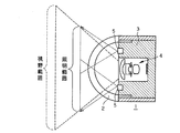
さて、図1のような先端構造を前後に配置してなる二眼配置のカプセル内視鏡10にする場合は、図2に示すように、前後の発光素子5による配光範囲(照明範囲)が相互に交わるように各端部の複数の発光素子5による照明範囲を180°より広くすることで(各端部の複数の発光素子5による軸方向の配光範囲も相互に交わるようにするのはもちろん)、カプセル内視鏡10周囲を略全て照明することができるようになり、図3に模式的に示すように、例えば小腸C内を死角がなく病変の見落としの確率が極めて小さく観察診断ができるようになる。
Now, in the case of the
図4(a)にカプセル内視鏡1の一方の先端部の構成例の断面図を示す。カプセル内視鏡の円筒状本体15の先端に、図4(b)に正面図を示すような保持枠30を固定し、その上に透明半球状のドーム2を被せてカプセル内視鏡1の先端部を構成する。保持枠30は、頂部の面の中心に対物レンズ4を取り付ける開口32を有する六角錐台の形状をした板金部材からなり、六角錐台の各側面には発光素子5を固定する開口33が設けられている。保持枠30の六角錐台の頂部の面の開口32に同軸に対物レンズ4の鏡筒を固定し、フレキシ基板20の前面に所定間隔で発光素子5が取り付けられたフレキシ基板20を保持枠30の内側面(裏面側の面)に押圧固定することで、保持枠30の各側面の開口33に各発光素子5が保持枠30の内側から挿入固定される。
FIG. 4A shows a cross-sectional view of a configuration example of one tip portion of the capsule endoscope 1. A holding
対物レンズ4は、例えば特許文献2に示されているように、物体側から順に、負の屈折力を有する物体側に凸のメニスカスレンズL1と、負の屈折力を有するレンズL2と、絞りSと、正の屈折力を有するレンズL3の3枚構成からなるものを用いて、観察できる視野角を140°以上、好ましくは180°以上にして死角範囲をなくし、病変の見落としを低減させる。そして、対物レンズ4の像面にCCD等の撮像素子21が配置され、この撮像素子21はフレキシ基板20に接続される。
For example, as shown in
このように、カプセル内視鏡1の先端部の構造として、対物レンズ4と発光素子5の配置位置を定めて位置を正確に決めることができる保持枠30を用いることで、撮像系と照明系を一体に保持する構造となり、対物レンズ4と発光素子5の配置を高精度に定めることが可能となる。また、発光素子5は自由に素子の方向を定められるフレキシ基板20に取り付けられているが、その発光素子5は何等かの保持構造がないと配置位置が不安定となり、配光バラツキやフレアの発生要因となってしまうが、上記のように、フレキシ基板20に付けられた発光素子5を固定し、対物レンズ4と発光素子5の位置を高精度に定めることができる一体の保持枠30を用いることで、配光バラツキ、不要光の低減を可能とすることが可能となると共に、組立性も向上する。
As described above, as the structure of the distal end portion of the capsule endoscope 1, by using the holding
とろで、本発明のカプセル内視鏡1においては、発光素子5を対物レンズ4周辺の保持枠30の斜めの側面に取り付ける構成とするため、対物レンズ4を透明半球状のドーム2内に突き出すような配置にすることができ、広視野化、広配光だけでなく、対物レンズ4のドーム2内への移動量分、ドーム2内のデットスペースを低減し、カプセル内視鏡1全体の全長を短くすることが可能となる。カプセル内視鏡1の全長が短くなることで、患者への負担を低減し、安全性も向上する。そのためには、次の条件式を満足することが望ましい。
In the capsule endoscope 1 of the present invention, since the
条件式(2) Ra>L
ただし、Raは透明ドーム2の対物レンズ4側面の曲率半径、Lは透明ドーム2の対物レンズ4側面の頂点から対物レンズの最も物体側の面(メニスカスレンズL1の物体側の面)までの距離である。
Conditional expression (2) Ra> L
Where Ra is the radius of curvature of the side surface of the objective lens 4 of the
この条件式(2)の範囲外では、上記全長短縮の効果を得ることができなくなる。 Outside the range of conditional expression (2), the effect of shortening the total length cannot be obtained.
次に、対物レンズ4の中心軸に対する発光素子5の放射方向中心軸がなす角度θの例とその場合の配光特性を図5に例示する。各発光素子5の配光特性はθ=0の場合が対応し、θが15°、30°、45°の配置角度における対物レンズ4の中心軸に対する角度0〜90°における配光特性は図5に示す通りである。配置角度θ=45°になると、対物レンズ4の中心軸に対して90°をなす周辺部においても明るく照明されていることが分かる。
Next, an example of an angle θ formed by the central axis of the
図6に、本発明で使用した発光素子の1例の物体が球面形状のときの配光特性を示す。発光素子の放射方向中心軸方向に出射される強度に対して10%の強度になる中心軸に対する角度は80°である。 FIG. 6 shows the light distribution characteristics when the object of one example of the light emitting element used in the present invention has a spherical shape. The angle with respect to the central axis that is 10% of the intensity emitted in the radial central axis direction of the light emitting element is 80 °.
図7に、この発光素子5を使用した本発明のカプセル内視鏡10の概略図を示す。前後に配置した発光素子5中心間の長手方向の距離Nは10mm、前後に配置された対物レンズ4先端中心間の長手方向の距離Mは11mm、発光素子5の放射方向中心軸方向に出射される強度強度に対して10%の強度になる中心軸に対する角度αは80°、対物レンズ4の中心軸に対する発光素子5の放射方向中心軸がなす角度θは35°、対物レンズ4の視野角の半分βは110°である。
In FIG. 7, the schematic of the
(N/2)/tan(β−90°)=13.7
(M/2)/tan(α+θ−90°)=11.8
となり、(N/2)/tan(β−90°)の方が大きくなっている。
(N / 2) / tan (β-90 °) = 13.7
(M / 2) / tan (α + θ−90 °) = 11.8
Thus, (N / 2) / tan (β-90 °) is larger.
条件式(3) (N/2)/tan(β−90°)
≧(M/2)/tan(α+θ−90°)
この条件式(3)を満たすことで、視野内に入る発光素子5からの出射光は10%以上になるため、対物レンズの視野角を広角にした際にも周辺まで明るい画像を観察することができる。
Conditional expression (3) (N / 2) / tan (β-90 °)
≧ (M / 2) / tan (α + θ−90 °)
By satisfying this conditional expression (3), the emitted light from the
以上、本発明のカプセル内視鏡を実施例に基づいて説明してきたが、本発明はこれら実施例に限定されず種々の変形が可能である。 As described above, the capsule endoscope of the present invention has been described based on the embodiments. However, the present invention is not limited to these embodiments, and various modifications can be made.
1…カプセル内視鏡
2…透明ドーム
3…枠部材
4…対物レンズ
5…発光素子
10…二眼配置のカプセル内視鏡
15…円筒状本体
20…フレキシ基板
21…撮像素子
30…保持枠
31…枠部材の先端面
32…対物レンズを取り付ける開口
33…発光素子を固定する開口
C…小腸
L1…負の屈折力を有する物体側に凸のメニスカスレンズ
L2…負の屈折力を有するレンズ
L3…正の屈折力を有するレンズ
S…絞り
DESCRIPTION OF SYMBOLS 1 ...
Claims (10)
前記対物レンズを保持し、かつ、前記発光素子を前記対物レンズの周辺の前記対物レンズ先端より後退した位置で前記対物レンズの中心軸に対して外側に傾けて斜めに保持する一体の保持部材を備えることを特徴とするカプセル内視鏡。 In a capsule endoscope comprising an objective lens, a transparent dome that covers the object side of the objective lens, and a light emitting element that is disposed on an outer peripheral portion around the objective lens,
An integral holding member that holds the objective lens and holds the light emitting element obliquely by tilting outward with respect to the central axis of the objective lens at a position retracted from the distal end of the objective lens around the objective lens. A capsule endoscope comprising the capsule endoscope.
前後に2つの対物レンズと、該対物レンズの物体側を覆う透明ドームと、該対物レンズの周辺の外周部に配置された発光素子が配置されており、前後に配置した発光素子の配光が前後で周辺で交わるように、前後の発光素子が各対物レンズ先端より後退した位置に各対物レンズの中心軸に対して外側に傾けて斜めに配置されていることを特徴とするカプセル内視鏡。 In a capsule endoscope comprising an objective lens, a transparent dome that covers the object side of the objective lens, and a light emitting element that is disposed on an outer peripheral portion around the objective lens,
Two objective lenses are arranged on the front and back, a transparent dome that covers the object side of the objective lens, and light emitting elements arranged on the outer periphery of the objective lens, and the light distribution of the light emitting elements arranged on the front and rear is Capsule endoscope characterized in that front and rear light emitting elements are inclined obliquely outward with respect to the central axis of each objective lens so that the front and rear light emitting elements intersect with each other at the front and rear sides .
条件式(1) 0°<θ≦60°
ただし、θは対物レンズの中心軸に対する発光素子の放射方向中心軸がなす角度である。 The capsule endoscope according to any one of claims 1 to 3, wherein a visual field range of the objective lens is 140 ° or more and satisfies the following conditional expression (1).
Conditional expression (1) 0 ° <θ ≦ 60 °
Here, θ is an angle formed by the central axis of the light emitting element in the radial direction with respect to the central axis of the objective lens.
条件式(2) Ra>L
ただし、Raは前記透明ドームの前記対物レンズ側面の曲率半径、Lは前記透明ドームの前記対物レンズ側面の頂点から前記対物レンズの最も物体側の面までの距離である。 The capsule endoscope according to claim 1, wherein the following conditional expression (2) is satisfied.
Conditional expression (2) Ra> L
Here, Ra is the radius of curvature of the objective lens side surface of the transparent dome, and L is the distance from the apex of the objective lens side surface of the transparent dome to the most object side surface of the objective lens.
条件式(3) (N/2)/tan(β−90°)
≧(M/2)/tan(α+θ−90°)
ただし、Nは前後に配置した発光素子中心間の長手方向の距離、Mは前後に配置された対物レンズ先端中心間の長手方向の距離、αは発光素子の放射方向中心軸方向に出射される強度強度に対して10%の強度になる中心軸に対する角度、βは対物レンズの視野角の半分、θは対物レンズの中心軸に対する発光素子の放射方向中心軸がなす角度である。 The capsule endoscope according to claim 3, wherein the following conditional expression (3) is satisfied.
Conditional expression (3) (N / 2) / tan (β-90 °)
≧ (M / 2) / tan (α + θ−90 °)
However, N is the distance in the longitudinal direction between the centers of the light emitting elements arranged in the front and back, M is the distance in the longitudinal direction between the centers of the front ends of the objective lenses arranged in the front and back, and α is emitted in the central axis direction of the light emitting element in the radial direction. The angle with respect to the central axis at which the intensity is 10% of the intensity intensity, β is half of the viewing angle of the objective lens, and θ is the angle formed by the central axis of the light emitting element in the radial direction with respect to the central axis of the objective lens.
Priority Applications (4)
| Application Number | Priority Date | Filing Date | Title |
|---|---|---|---|
| JP2007231362A JP2009061097A (en) | 2007-09-06 | 2007-09-06 | Capsule endoscope |
| EP08010175.1A EP2033570B1 (en) | 2007-09-06 | 2008-06-04 | Capsule endoscope |
| US12/228,825 US20090069633A1 (en) | 2007-09-06 | 2008-08-15 | Capsule endoscope |
| CN200810147212.7A CN101380219B (en) | 2007-09-06 | 2008-08-21 | Capsule endoscope |
Applications Claiming Priority (1)
| Application Number | Priority Date | Filing Date | Title |
|---|---|---|---|
| JP2007231362A JP2009061097A (en) | 2007-09-06 | 2007-09-06 | Capsule endoscope |
Related Child Applications (1)
| Application Number | Title | Priority Date | Filing Date |
|---|---|---|---|
| JP2011263256A Division JP2012086029A (en) | 2011-12-01 | 2011-12-01 | Capsule endoscope |
Publications (2)
| Publication Number | Publication Date |
|---|---|
| JP2009061097A true JP2009061097A (en) | 2009-03-26 |
| JP2009061097A5 JP2009061097A5 (en) | 2009-11-19 |
Family
ID=40028975
Family Applications (1)
| Application Number | Title | Priority Date | Filing Date |
|---|---|---|---|
| JP2007231362A Pending JP2009061097A (en) | 2007-09-06 | 2007-09-06 | Capsule endoscope |
Country Status (4)
| Country | Link |
|---|---|
| US (1) | US20090069633A1 (en) |
| EP (1) | EP2033570B1 (en) |
| JP (1) | JP2009061097A (en) |
| CN (1) | CN101380219B (en) |
Cited By (2)
| Publication number | Priority date | Publication date | Assignee | Title |
|---|---|---|---|---|
| WO2016103446A1 (en) * | 2014-12-26 | 2016-06-30 | オリンパス株式会社 | Optical system and capsule endoscope |
| JP2023513476A (en) * | 2020-01-31 | 2023-03-31 | コスモイースセティクス ピーティーワイ リミテッド | Ingestible therapeutic device for the treatment of gastritis |
Families Citing this family (21)
| Publication number | Priority date | Publication date | Assignee | Title |
|---|---|---|---|---|
| JP5441465B2 (en) | 2009-03-24 | 2014-03-12 | 富士フイルム株式会社 | Capsule endoscope |
| TWI539925B (en) * | 2011-01-18 | 2016-07-01 | Medical Intubation Tech Corp | An endoscopic image pickup assembly having two or more illumination directions |
| US20120229426A1 (en) * | 2011-03-09 | 2012-09-13 | Avermedia Information, Inc. | Pen-shaped input apparatus |
| CN102305966B (en) * | 2011-05-16 | 2014-07-02 | 深圳市资福技术有限公司 | Capsule endoscopy |
| US9071740B1 (en) | 2011-10-28 | 2015-06-30 | Google Inc. | Modular camera system |
| US9197686B1 (en) | 2012-01-06 | 2015-11-24 | Google Inc. | Backfill of video stream |
| EP3005669B1 (en) * | 2013-06-06 | 2019-04-17 | Dolby Laboratories Licensing Corporation | Lighting for audio devices |
| US9544485B2 (en) | 2015-05-27 | 2017-01-10 | Google Inc. | Multi-mode LED illumination system |
| US9386230B1 (en) | 2015-06-12 | 2016-07-05 | Google Inc. | Day and night detection based on one or more of illuminant detection, lux level detection, and tiling |
| US9235899B1 (en) | 2015-06-12 | 2016-01-12 | Google Inc. | Simulating an infrared emitter array in a video monitoring camera to construct a lookup table for depth determination |
| US9454820B1 (en) | 2015-06-12 | 2016-09-27 | Google Inc. | Using a scene illuminating infrared emitter array in a video monitoring camera for depth determination |
| US9554063B2 (en) | 2015-06-12 | 2017-01-24 | Google Inc. | Using infrared images of a monitored scene to identify windows |
| US9886620B2 (en) | 2015-06-12 | 2018-02-06 | Google Llc | Using a scene illuminating infrared emitter array in a video monitoring camera to estimate the position of the camera |
| CN105769111A (en) * | 2016-02-29 | 2016-07-20 | 吉林大学 | Wide-angle double-camera capsule endoscopy |
| US10180615B2 (en) | 2016-10-31 | 2019-01-15 | Google Llc | Electrochromic filtering in a camera |
| DE102017107106A1 (en) | 2017-04-03 | 2018-10-04 | Hoya Corporation | ENDOSCOPE WITH WIDE ANGLE OPTICS AND WORKING CHANNEL |
| CN108508590A (en) * | 2018-04-19 | 2018-09-07 | 深圳市都乐精密制造有限公司 | Wide-angle capsule lens are peeped in medical |
| CN113907692B (en) * | 2020-07-10 | 2024-12-24 | 紫东信息科技(苏州)有限公司 | Capsule endoscope |
| DE102020122636A1 (en) * | 2020-08-31 | 2022-03-03 | Hoya Corporation | Lighting device for an endoscope |
| TWI761974B (en) * | 2020-09-29 | 2022-04-21 | 醫電鼎眾股份有限公司 | Modular combination of endoscope light source and imaging module |
| CN118216863B (en) * | 2024-05-24 | 2024-08-27 | 北京大学第三医院(北京大学第三临床医学院) | Compact wide-angle surgical endoscope based on observation three-dimensional space depth representation |
Citations (8)
| Publication number | Priority date | Publication date | Assignee | Title |
|---|---|---|---|---|
| JP2003260025A (en) * | 2002-03-08 | 2003-09-16 | Olympus Optical Co Ltd | Capsule endoscope |
| JP2004275542A (en) * | 2003-03-17 | 2004-10-07 | Olympus Corp | Capsule type endoscope |
| WO2004096029A1 (en) * | 2003-04-25 | 2004-11-11 | Olympus Corporation | Capsule endoscope and capsule endoscope system |
| JP2005503182A (en) * | 2001-01-16 | 2005-02-03 | ギブン・イメージング・リミテツド | System and method for wide area imaging of body cavities |
| JP2005080713A (en) * | 2003-09-04 | 2005-03-31 | Olympus Corp | Capsule type endoscope |
| WO2006003649A2 (en) * | 2004-06-30 | 2006-01-12 | Given Imaging Ltd. | Device and method for in-vivo illumination |
| JP2006527012A (en) * | 2003-05-01 | 2006-11-30 | ギブン・イメージング・リミテツド | Panorama field of view imaging device |
| JP2007044214A (en) * | 2005-08-09 | 2007-02-22 | Olympus Medical Systems Corp | In vivo information acquisition device |
Family Cites Families (12)
| Publication number | Priority date | Publication date | Assignee | Title |
|---|---|---|---|---|
| US5547455A (en) * | 1994-03-30 | 1996-08-20 | Medical Media Systems | Electronically steerable endoscope |
| IL134017A (en) * | 2000-01-13 | 2008-04-13 | Capsule View Inc | Camera for viewing inside intestines |
| JP4363843B2 (en) * | 2002-03-08 | 2009-11-11 | オリンパス株式会社 | Capsule endoscope |
| US8449452B2 (en) * | 2002-09-30 | 2013-05-28 | Given Imaging Ltd. | In-vivo sensing system |
| US7153259B2 (en) * | 2003-09-01 | 2006-12-26 | Olympus Corporation | Capsule type endoscope |
| JP2005074031A (en) * | 2003-09-01 | 2005-03-24 | Pentax Corp | Capsule endoscope |
| JP4554267B2 (en) * | 2004-04-27 | 2010-09-29 | オリンパス株式会社 | Endoscope and endoscope system |
| US20060015013A1 (en) * | 2004-06-30 | 2006-01-19 | Zvika Gilad | Device and method for in vivo illumination |
| US7585275B2 (en) * | 2005-01-18 | 2009-09-08 | Hoya Corporation | Capsule endoscope |
| US20060217593A1 (en) * | 2005-03-24 | 2006-09-28 | Zvika Gilad | Device, system and method of panoramic multiple field of view imaging |
| US7896805B2 (en) * | 2005-11-23 | 2011-03-01 | Given Imaging Ltd. | In-vivo imaging device and optical system thereof |
| JP5006596B2 (en) * | 2006-08-21 | 2012-08-22 | オリンパスメディカルシステムズ株式会社 | Capsule endoscope |
-
2007
- 2007-09-06 JP JP2007231362A patent/JP2009061097A/en active Pending
-
2008
- 2008-06-04 EP EP08010175.1A patent/EP2033570B1/en not_active Not-in-force
- 2008-08-15 US US12/228,825 patent/US20090069633A1/en not_active Abandoned
- 2008-08-21 CN CN200810147212.7A patent/CN101380219B/en not_active Expired - Fee Related
Patent Citations (8)
| Publication number | Priority date | Publication date | Assignee | Title |
|---|---|---|---|---|
| JP2005503182A (en) * | 2001-01-16 | 2005-02-03 | ギブン・イメージング・リミテツド | System and method for wide area imaging of body cavities |
| JP2003260025A (en) * | 2002-03-08 | 2003-09-16 | Olympus Optical Co Ltd | Capsule endoscope |
| JP2004275542A (en) * | 2003-03-17 | 2004-10-07 | Olympus Corp | Capsule type endoscope |
| WO2004096029A1 (en) * | 2003-04-25 | 2004-11-11 | Olympus Corporation | Capsule endoscope and capsule endoscope system |
| JP2006527012A (en) * | 2003-05-01 | 2006-11-30 | ギブン・イメージング・リミテツド | Panorama field of view imaging device |
| JP2005080713A (en) * | 2003-09-04 | 2005-03-31 | Olympus Corp | Capsule type endoscope |
| WO2006003649A2 (en) * | 2004-06-30 | 2006-01-12 | Given Imaging Ltd. | Device and method for in-vivo illumination |
| JP2007044214A (en) * | 2005-08-09 | 2007-02-22 | Olympus Medical Systems Corp | In vivo information acquisition device |
Cited By (3)
| Publication number | Priority date | Publication date | Assignee | Title |
|---|---|---|---|---|
| WO2016103446A1 (en) * | 2014-12-26 | 2016-06-30 | オリンパス株式会社 | Optical system and capsule endoscope |
| JP2023513476A (en) * | 2020-01-31 | 2023-03-31 | コスモイースセティクス ピーティーワイ リミテッド | Ingestible therapeutic device for the treatment of gastritis |
| JP7682554B2 (en) | 2020-01-31 | 2025-05-26 | コスモイースセティクス ピーティーワイ リミテッド | Ingestible therapeutic device for the treatment of gastritis - Patent Application 20070229633 |
Also Published As
| Publication number | Publication date |
|---|---|
| EP2033570A1 (en) | 2009-03-11 |
| EP2033570B1 (en) | 2013-04-24 |
| CN101380219B (en) | 2012-10-10 |
| US20090069633A1 (en) | 2009-03-12 |
| CN101380219A (en) | 2009-03-11 |
Similar Documents
| Publication | Publication Date | Title |
|---|---|---|
| JP2009061097A (en) | Capsule endoscope | |
| JP4704386B2 (en) | Endoscope | |
| US9622652B2 (en) | Endoscope objective optical system | |
| JP4727959B2 (en) | Endoscope optical system | |
| CN103562770B (en) | Endoscope tip component and endoscope | |
| JP2006072098A5 (en) | ||
| JP5897224B2 (en) | Endoscope device | |
| US6384988B1 (en) | Illuminated optical enlargement device | |
| JP2008055159A5 (en) | ||
| US11278186B2 (en) | Endoscope system and optical adaptor for endoscope | |
| JP5866565B1 (en) | Endoscope | |
| WO2011027622A1 (en) | Objective optical system | |
| JP3142994U (en) | Dark field illumination device | |
| JP2004016455A (en) | Endoscope tip | |
| JP5242281B2 (en) | Objective lens and objective lens adapter | |
| JP2015045837A (en) | Endoscope lens unit and endoscope having the same | |
| JP2012086029A (en) | Capsule endoscope | |
| JP2011033958A (en) | Light source device | |
| JP2014191222A (en) | Endoscope lens unit and endoscope having the same | |
| JP2006255247A (en) | Capsule endoscope | |
| CN112748556A (en) | Endoscope optical system | |
| JP2013094259A (en) | Endoscope | |
| US20140009958A1 (en) | Endoscopic Illumination Optical System | |
| JP4147037B2 (en) | Illumination system and endoscope having the same | |
| JP5317639B2 (en) | Endoscope |
Legal Events
| Date | Code | Title | Description |
|---|---|---|---|
| A521 | Request for written amendment filed |
Free format text: JAPANESE INTERMEDIATE CODE: A523 Effective date: 20091002 |
|
| A621 | Written request for application examination |
Free format text: JAPANESE INTERMEDIATE CODE: A621 Effective date: 20091002 |
|
| A977 | Report on retrieval |
Free format text: JAPANESE INTERMEDIATE CODE: A971007 Effective date: 20111006 |
|
| A131 | Notification of reasons for refusal |
Free format text: JAPANESE INTERMEDIATE CODE: A131 Effective date: 20111012 |
|
| A02 | Decision of refusal |
Free format text: JAPANESE INTERMEDIATE CODE: A02 Effective date: 20120307 |