[go: up one dir, main page]

JP2009053662A - Cassette - Google Patents

Cassette Download PDF

Info

Publication number
JP2009053662A
JP2009053662A JP2008150561A JP2008150561A JP2009053662A JP 2009053662 A JP2009053662 A JP 2009053662A JP 2008150561 A JP2008150561 A JP 2008150561A JP 2008150561 A JP2008150561 A JP 2008150561A JP 2009053662 A JP2009053662 A JP 2009053662A
Authority
JP
Japan
Prior art keywords
radiation
cassette
patient
radiation detection
detection cassette
Prior art date
Legal status (The legal status is an assumption and is not a legal conclusion. Google has not performed a legal analysis and makes no representation as to the accuracy of the status listed.)
Abandoned
Application number
JP2008150561A
Other languages
Japanese (ja)
Inventor
Takuya Yoshimi
琢也 吉見
Hidekazu Kito
英一 鬼頭
Takeshi Tanabe
剛 田辺
Takeshi Kuwabara
健 桑原
Kazuharu Ueda
和治 植田
Makoto Iriuchijima
誠 入内島
Yasuyoshi Ota
恭義 大田
Current Assignee (The listed assignees may be inaccurate. Google has not performed a legal analysis and makes no representation or warranty as to the accuracy of the list.)
Fujifilm Corp
Original Assignee
Fujifilm Corp
Priority date (The priority date is an assumption and is not a legal conclusion. Google has not performed a legal analysis and makes no representation as to the accuracy of the date listed.)
Filing date
Publication date
Application filed by Fujifilm Corp filed Critical Fujifilm Corp
Priority to JP2008150561A priority Critical patent/JP2009053662A/en
Priority to US12/219,734 priority patent/US7663112B2/en
Publication of JP2009053662A publication Critical patent/JP2009053662A/en
Priority to US12/654,481 priority patent/US20100148081A1/en
Abandoned legal-status Critical Current

Links

Images

Landscapes

  • Measurement Of Radiation (AREA)
  • Radiography Using Non-Light Waves (AREA)
  • Apparatus For Radiation Diagnosis (AREA)

Abstract

【課題】被写体と臥台との間への設置を容易とし、該被写体への負担を軽減すると共に、その設置作業を効率的に行い、且つ、小型化を図る。
【解決手段】放射線検出カセッテ24のケーシング36には、患者14に臨む第1平板部38と手術台16に臨む第2平板部40とが所定間隔離間して設けられ、前記第1及び第2平板部38、40の間に放射線検出器52が配設されると共に、前記第1及び第2平板部38、40の両側部に、徐々に先細状となる第1及び第2テーパ部42、44が形成される。そして、第1及び第2テーパ部42、44の内部には、放射線遮断部材60a、60bを介してバッテリ62、カセッテ制御部64及び送受信機66が収容される。
【選択図】図2
An object of the present invention is to facilitate installation between a subject and a table, to reduce the burden on the subject, to efficiently perform the installation work, and to reduce the size.
A casing 36 of a radiation detection cassette 24 is provided with a first flat plate portion 38 facing the patient 14 and a second flat plate portion 40 facing the operating table 16 spaced apart from each other by a predetermined distance. A radiation detector 52 is disposed between the flat plate portions 38 and 40, and first and second tapered portions 42 that gradually taper on both sides of the first and second flat plate portions 38 and 40, 44 is formed. In addition, the battery 62, the cassette control unit 64, and the transceiver 66 are accommodated in the first and second tapered portions 42, 44 via the radiation blocking members 60a, 60b.
[Selection] Figure 2

Description

本発明は、被写体を透過した放射線を検出し、放射線画像情報に変換する放射線変換パネルを収容したカセッテに関する。   The present invention relates to a cassette containing a radiation conversion panel that detects radiation transmitted through a subject and converts it into radiation image information.

医療分野において、被写体に放射線を照射し、被写体を透過した放射線を放射線変換パネルに導いて放射線画像を撮影する放射線画像撮影装置が広汎に使用されている。この場合、放射線変換パネルとしては、放射線画像が露光記録される従来からの放射線フイルムや、蛍光体に放射線画像としての放射線エネルギを蓄積し、励起光を照射することで放射線画像を輝尽発光光として取り出すことのできる蓄積性蛍光体パネルが知られている。これらの放射線変換パネルは、放射線画像が記録された放射線フイルムを現像装置に供給して現像処理を行い、あるいは、蓄積性蛍光体パネルを読取装置に供給して読取処理を行うことで、可視画像としての放射線画像が得られる。   2. Description of the Related Art In the medical field, a radiation image capturing apparatus that irradiates a subject with radiation and guides the radiation transmitted through the subject to a radiation conversion panel to capture a radiation image is widely used. In this case, the radiation conversion panel is a conventional radiation film in which a radiation image is exposed and recorded, or radiation energy as a radiation image is accumulated in a phosphor and irradiated with excitation light, and the radiation image is then emitted as a stimulating light. A storage phosphor panel that can be taken out as is known. These radiation conversion panels supply a radiation film on which a radiographic image is recorded to a developing device to perform development processing, or supply a stimulable phosphor panel to a reading device to perform reading processing so that a visible image can be obtained. A radiographic image is obtained.

一方、手術室等においては、患者に対して迅速且つ的確な処置を施すため、撮影後の放射線変換パネルから直ちに放射線画像を読み出して表示できることが必要である。このような要求に対応可能な放射線変換パネルとして、放射線を直接電気信号に変換し、あるいは、放射線をシンチレータで可視光に変換した後、電気信号に変換して読み出す固体検出素子を用いた放射線検出器が開発されている。   On the other hand, in an operating room or the like, it is necessary to be able to immediately read out and display a radiation image from a radiation conversion panel after imaging in order to perform a quick and accurate treatment on a patient. Radiation detection using a solid-state detector that converts radiation directly into electrical signals, or converts radiation into visible light with a scintillator and then converts it into electrical signals to read out as a radiation conversion panel that can meet such demands A vessel has been developed.

このような放射線変換パネルは、無線通信手段及びバッテリと共にカセッテに収容され、前記放射線変換パネルの撮影面に対峙した放射線源からX線を照射している(例えば、特許文献1参照)。   Such a radiation conversion panel is accommodated in a cassette together with wireless communication means and a battery, and irradiates X-rays from a radiation source facing the imaging surface of the radiation conversion panel (see, for example, Patent Document 1).

特開2003−172783号公報JP 2003-172783 A

ところで、このようなカセッテは、例えば、ベッド上に臥位している患者と前記ベッドとの間に配置され、該患者の患部に対応した位置に設置されて撮影が行われる。しかしながら、一般的に、カセッテは、薄型箱状に形成され、且つ、患者とベッドとの間に挿入するように設置させる必要があるため、前記患者に対する負担が大きく、しかも、その設置作業が困難となる。そのため、カセッテの設置作業をより簡便且つ効率的に行いたいという要請がある。   By the way, such a cassette is placed between a patient lying on a bed and the bed, for example, and is placed at a position corresponding to the affected area of the patient to perform imaging. However, generally, since the cassette is formed in a thin box shape and needs to be installed so as to be inserted between the patient and the bed, the burden on the patient is large, and the installation work is difficult. It becomes. For this reason, there is a demand for more convenient and efficient installation of the cassette.

本発明は、前記の課題を考慮してなされたものであり、被写体と臥台との間への設置を容易とし、その設置作業による該被写体への負担を軽減すると共に、作業を効率的に行い、且つ、小型化を図ることが可能なカセッテを提供することを目的とする。   The present invention has been made in consideration of the above-mentioned problems, facilitates installation between the subject and the base, reduces the burden on the subject due to the installation work, and efficiently performs the work. It is an object to provide a cassette that can be performed and can be miniaturized.

前記の目的を達成するために、本発明は、放射線源から照射され被写体を透過した放射線を検出し、放射線画像情報に変換可能な放射線変換パネルが収容された筐体と、
前記筐体に設けられ、先端に向かって徐々に先細状となるテーパ部と、
を備え、
前記テーパ部は、前記筐体が前記被写体と該被写体が臥位する臥台との間に設置される際、前記被写体及び臥台に対峙しない前記筐体の側面に設けられると共に、前記テーパ部の内部には、外部と無線通信が可能な無線通信手段を備えることを特徴とする。
In order to achieve the above-mentioned object, the present invention detects a radiation irradiated from a radiation source and transmitted through a subject, and a housing that accommodates a radiation conversion panel that can be converted into radiation image information;
A tapered portion provided in the housing and gradually tapering toward the tip;
With
The taper portion is provided on a side surface of the housing that does not face the subject and the base when the case is installed between the subject and the base on which the subject stands. Is provided with wireless communication means capable of wireless communication with the outside.

本発明によれば、放射線変換パネルの収容された筐体には、先端に向かって徐々に先細状となるテーパ部を備え、前記テーパ部の内部に外部と無線通信が可能な無線通信手段を収容しているため、前記該筐体を含むカセッテが被写体と該被写体が臥位する臥台との間に設置する際、前記被写体及び臥台に対峙しない側面に設けられたテーパ部によって前記被写体と臥台との間に徐々に進入させることが可能となる。従って、テーパ部を介してカセッテを被写体と臥台との間に容易に進入させて設置することができ、しかも、その設置作業による被写体への負担を軽減させることができる。その結果、カセッテの設置作業を効率的に行うことができる。また、テーパ部内に無線通信手段を収容することにより、筐体内のスペースを有効に利用することができ、該筐体を含むカセッテの小型化を図ることが可能となる。   According to the present invention, the housing in which the radiation conversion panel is housed includes a tapered portion that gradually tapers toward the tip, and wireless communication means capable of wireless communication with the outside is provided inside the tapered portion. When the cassette including the housing is installed between the subject and the stand on which the subject is placed, the subject is provided by a tapered portion provided on a side surface that does not face the subject and the stand. It is possible to make it gradually enter between the base and the stand. Therefore, the cassette can be easily entered between the subject and the base via the taper portion, and the burden on the subject due to the installation work can be reduced. As a result, the cassette can be installed efficiently. Further, by accommodating the wireless communication means in the tapered portion, the space in the housing can be used effectively, and the cassette including the housing can be downsized.

図1は、本実施の形態に係るカセッテが用いられた放射線画像撮影システム10が設置された手術室12の説明図である。手術室12には、放射線画像撮影システム10に加えて、患者(被写体)14が横臥する手術台(臥台)16が配置されると共に、医師18が手術に使用する各種器具が載置される器具台20が手術台16の側部に配置される。また、手術台16には、麻酔器、吸引器、心電計、血圧計等、手術に必要な様々な機器が配置される。   FIG. 1 is an explanatory diagram of an operating room 12 in which a radiographic imaging system 10 using a cassette according to the present embodiment is installed. In the operating room 12, in addition to the radiographic imaging system 10, an operating table (table) 16 on which a patient (subject) 14 lies is placed, and various instruments used by a doctor 18 for surgery are placed. An instrument table 20 is disposed on the side of the operating table 16. The operating table 16 is provided with various devices necessary for surgery, such as an anesthesia machine, aspirator, electrocardiograph, and blood pressure monitor.

放射線画像撮影システム10は、撮影条件に従った線量からなる放射線Xを患者14に照射する撮影装置22と、患者14を透過した放射線Xを検出する放射線検出器(放射線変換パネル)52(後述する)を内蔵した放射線検出カセッテ(カセッテ)24と、放射線検出器52によって検出された放射線Xに基づく放射線画像を表示する表示装置26と、前記撮影装置22、放射線検出カセッテ24及び表示装置26を制御するコンソール28とを備える。この撮影装置22、放射線検出カセッテ24、表示装置26及びコンソール28間では、無線通信による信号の送受信が行われる。   The radiographic imaging system 10 includes an imaging device 22 that irradiates a patient 14 with radiation X having a dose according to imaging conditions, and a radiation detector (radiation conversion panel) 52 (described later) that detects the radiation X transmitted through the patient 14. ) Built-in radiation detection cassette (cassette) 24, a display device 26 for displaying a radiation image based on the radiation X detected by the radiation detector 52, the imaging device 22, the radiation detection cassette 24 and the display device 26 are controlled. Console 28. Signals are transmitted and received by wireless communication among the imaging device 22, the radiation detection cassette 24, the display device 26, and the console 28.

撮影装置22は、複数の自在アーム32によって移動自在に設けられ、患者14の撮影部位に応じた所望の位置に移動可能であると共に、医師18による手術の邪魔とならない位置に待避可能である。同様に、表示装置26は、自在アーム34に連結され、撮影された放射線画像を医師18が容易に確認できる位置に移動可能である。   The imaging device 22 is movably provided by a plurality of free arms 32, can be moved to a desired position according to the imaging region of the patient 14, and can be retracted to a position that does not obstruct the operation by the doctor 18. Similarly, the display device 26 is connected to the universal arm 34 and can be moved to a position where the doctor 18 can easily confirm the captured radiographic image.

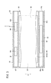
図2〜図4は、放射線検出カセッテ24の外観及び内部構成図である。   2 to 4 are an external view and an internal configuration diagram of the radiation detection cassette 24.

放射線検出カセッテ24は、放射線Xを透過させる材料からなるケーシング(筐体)36を備える。このケーシング36は、略長方形状で所定間隔離間した一組の第1及び第2平板部38、40と、該第1及び第2平板部38、40の長手方向に沿った両側部に設けられる一組の第1及び第2テーパ部42、44と、前記第1及び第2平板部38、40、第1及び第2テーパ部42、44に対して略直交し、その端部を閉塞する一組の接続壁46a、46bとから構成される。なお、ケーシング36は、第1平板部38が撮影装置22に臨み、第2平板部40が手術台16に臨むように配置される。   The radiation detection cassette 24 includes a casing (housing) 36 made of a material that transmits the radiation X. The casing 36 is provided in a pair of first and second flat plate portions 38 and 40 which are substantially rectangular and spaced apart from each other by a predetermined distance, and on both side portions along the longitudinal direction of the first and second flat plate portions 38 and 40. The pair of first and second taper portions 42 and 44, the first and second flat plate portions 38 and 40, and the first and second taper portions 42 and 44 are substantially orthogonal to each other and block their ends. It is composed of a set of connection walls 46a and 46b. The casing 36 is disposed such that the first flat plate portion 38 faces the imaging device 22 and the second flat plate portion 40 faces the operating table 16.

この放射線検出カセッテ24を構成する第1平板部38と第2平板部40との間には、放射線Xが照射されるケーシング36の照射面48側から、患者14による放射線Xの散乱線を除去するグリッド50、患者14を透過した放射線Xを検出する放射線検出器52、及び、前記放射線Xのバック散乱線を吸収する鉛板54が順に配設される。なお、ケーシング36の照射面48をグリッドとして構成してもよい。   Between the first flat plate portion 38 and the second flat plate portion 40 constituting the radiation detection cassette 24, the scattered radiation of the radiation X by the patient 14 is removed from the irradiation surface 48 side of the casing 36 irradiated with the radiation X. A grid 50, a radiation detector 52 that detects the radiation X transmitted through the patient 14, and a lead plate 54 that absorbs the back scattered radiation of the radiation X are arranged in this order. In addition, you may comprise the irradiation surface 48 of the casing 36 as a grid.

第1及び第2テーパ部42、44は、断面略V字状に形成され、第1及び第2平板部38、40の両側部から離間する方向に徐々に先細となるテーパ状に形成される。   The first and second taper portions 42 and 44 are formed in a substantially V-shaped cross section, and are formed in a taper shape that gradually tapers in a direction away from both side portions of the first and second flat plate portions 38 and 40. .

この第1及び第2テーパ部42、44は、第1平板部38に接合され、所定角度で下方に向かって延在する第1傾斜部56と、第2平板部40に接合され、所定角度で上方に向かって延在する第2傾斜部58とから構成され、前記第1傾斜部56の端部と第2傾斜部58の端部とが第1及び第2平板部38、40から所定間隔離間した位置で互いに接合される。なお、第1及び第2テーパ部42、44は、第1及び第2平板部38、40を挟んで互いに離間する方向に向かって先細状となった対称形状で形成される。   The first and second taper portions 42 and 44 are joined to the first flat plate portion 38 and joined to the first inclined portion 56 extending downward at a predetermined angle and the second flat plate portion 40 at a predetermined angle. And an end portion of the first inclined portion 56 and an end portion of the second inclined portion 58 are predetermined from the first and second flat plate portions 38 and 40, respectively. They are joined together at spaced apart positions. The first and second taper portions 42 and 44 are formed in a symmetrical shape that tapers in a direction away from each other with the first and second flat plate portions 38 and 40 interposed therebetween.

すなわち、ケーシング36は、その長手方向と直交した幅方向(矢印A方向)の略中央部が、第1及び第2平板部38、40によって一定厚さで形成され、前記幅方向(矢印A方向)の両端部が外側に向かって徐々に厚さが薄くなるように形成される。換言すれば、ケーシング36を含む放射線検出カセッテ24は、幅方向(矢印A方向)における両端部から中央部に向かって厚肉状となるように形成されている。   That is, the casing 36 is formed with a substantially central portion in the width direction (arrow A direction) orthogonal to the longitudinal direction by the first and second flat plate portions 38 and 40, and the width direction (arrow A direction). ) Are formed so that the thickness gradually decreases toward the outside. In other words, the radiation detection cassette 24 including the casing 36 is formed so as to be thicker from both ends in the width direction (arrow A direction) toward the center.

第1テーパ部42の内部には、その内壁面に沿って放射線Xの透過を遮断可能な放射線遮断部材60aが設けられ、中空状に形成された放射線遮断部材60aの内部に放射線検出カセッテ24の電源であるバッテリ62が収容される。   A radiation blocking member 60a capable of blocking the transmission of the radiation X along the inner wall surface is provided inside the first taper portion 42, and the radiation detection cassette 24 is disposed inside the radiation blocking member 60a formed in a hollow shape. A battery 62 as a power source is accommodated.

一方、第2テーパ部44の内部には、第1テーパ部42と同様に、内壁面に沿って放射線Xの透過を遮断可能な放射線遮断部材60bが設けられ、中空状に形成された放射線遮断部材60bの内部には、前記バッテリ62から供給される電力により放射線検出器52を駆動制御するカセッテ制御部64と、前記放射線検出器52によって検出した放射線Xの情報を含む信号をコンソール28との間で送受信する送受信機(無線通信手段)66とが収容される。この放射線遮断部材60a、60bは、例えば、シート状の鉛から形成された放射線遮断シートからなる。   On the other hand, a radiation blocking member 60b capable of blocking the transmission of the radiation X along the inner wall surface is provided inside the second taper portion 44, similarly to the first taper portion 42, and the radiation blocking member is formed in a hollow shape. Inside the member 60b, there is a cassette control unit 64 that drives and controls the radiation detector 52 by the electric power supplied from the battery 62, and a signal including information on the radiation X detected by the radiation detector 52 is sent to the console 28. A transmitter / receiver (wireless communication means) 66 for transmitting and receiving data is accommodated. The radiation blocking members 60a and 60b are made of, for example, a radiation blocking sheet formed from sheet-like lead.

このように、第1及び第2テーパ部42、44に筒状の放射線遮断部材60a、60bを設け、その内部にバッテリ62、カセッテ制御部64及び送受信機66を収容することにより、ケーシング36の照射面48に照射される放射線Xによる損傷を回避することが可能となり、前記バッテリ62、カセッテ制御部64及び送受信機66が好適に保護されることとなる。   As described above, the cylindrical radiation blocking members 60a and 60b are provided in the first and second taper portions 42 and 44, and the battery 62, the cassette control unit 64, and the transceiver 66 are accommodated therein, so that the casing 36 It is possible to avoid damage due to the radiation X irradiated to the irradiation surface 48, and the battery 62, the cassette control unit 64, and the transceiver 66 are suitably protected.

なお、第1及び第2テーパ部42、44に収容されるバッテリ62、カセッテ制御部64及び送受信機66の配置は、上述した場合に限定されるものではなく、例えば、第1テーパ部42に前記バッテリ62、カセッテ制御部64及び送受信機66の全てを収容するようにしてもよいし、反対に、第2テーパ部44に前記バッテリ62、カセッテ制御部64及び送受信機66の全てを収容するようにしてもよい。   In addition, arrangement | positioning of the battery 62 accommodated in the 1st and 2nd taper parts 42 and 44, the cassette control part 64, and the transmitter / receiver 66 is not limited to the case mentioned above, For example, the 1st taper part 42 is arranged. The battery 62, the cassette control unit 64, and the transmitter / receiver 66 may all be accommodated. Conversely, the battery 62, the cassette control unit 64, and the transmitter / receiver 66 are all accommodated in the second taper portion 44. You may do it.

一組の接続壁46a、46bは、第1及び第2平板部38、40、第1及び第2テーパ部42、44とからなる断面形状に応じた扁平菱形状に形成される。   The pair of connection walls 46a and 46b are formed in a flat rhombus shape corresponding to the cross-sectional shape including the first and second flat plate portions 38 and 40 and the first and second tapered portions 42 and 44.

図5は、放射線検出器52の回路構成ブロック図である。放射線検出器52は、放射線Xを感知して電荷を発生させるアモルファスセレン(a−Se)等の物質からなる光電変換層69を行列状の薄膜トランジスタ(TFT:Thin Film Transistor)70のアレイの上に配置した構造を有し、発生した電荷を蓄積容量71に蓄積した後、各行毎にTFT70を順次オンにして、電荷を画像信号として読み出す。図5では、光電変換層69及び蓄積容量71からなる1つの画素68と1つのTFT70との接続関係のみを示し、その他の画素68の構成については省略している。なお、アモルファスセレンは、高温になると構造が変化して機能が低下してしまうため、所定の温度範囲内で使用する必要がある。従って、放射線検出カセッテ24内に放射線検出器52を冷却する手段を配設することが好ましい。   FIG. 5 is a circuit configuration block diagram of the radiation detector 52. The radiation detector 52 has a photoelectric conversion layer 69 made of a material such as amorphous selenium (a-Se) that senses the radiation X and generates charges on an array of thin film transistors (TFTs) 70. After the generated charge is stored in the storage capacitor 71, the TFTs 70 are sequentially turned on for each row, and the charge is read as an image signal. In FIG. 5, only the connection relationship between one pixel 68 including the photoelectric conversion layer 69 and the storage capacitor 71 and one TFT 70 is shown, and the configuration of the other pixels 68 is omitted. Amorphous selenium must be used within a predetermined temperature range because its structure changes and its function decreases at high temperatures. Therefore, it is preferable to provide means for cooling the radiation detector 52 in the radiation detection cassette 24.

各画素68に接続されるTFT70には、行方向と平行に延びるゲート線72と、列方向と平行に延びる信号線74とが接続される。各ゲート線72は、ライン走査駆動部76に接続され、各信号線74は、読取回路を構成するマルチプレクサ84に接続される。   A gate line 72 extending parallel to the row direction and a signal line 74 extending parallel to the column direction are connected to the TFT 70 connected to each pixel 68. Each gate line 72 is connected to a line scanning drive unit 76, and each signal line 74 is connected to a multiplexer 84 constituting a reading circuit.

ゲート線72には、行方向に配列されたTFT70をオンオフ制御する制御信号Von、Voffがライン走査駆動部76から供給される。この場合、ライン走査駆動部76は、ゲート線72を切り替える複数のスイッチSW1と、スイッチSW1の1つを選択する選択信号を出力するアドレスデコーダ78とを備える。アドレスデコーダ78には、カセッテ制御部64からアドレス信号が供給される。   Control signals Von and Voff for controlling on / off of the TFTs 70 arranged in the row direction are supplied from the line scanning drive unit 76 to the gate line 72. In this case, the line scan driving unit 76 includes a plurality of switches SW1 for switching the gate lines 72 and an address decoder 78 for outputting a selection signal for selecting one of the switches SW1. An address signal is supplied to the address decoder 78 from the cassette control unit 64.

また、信号線74には、列方向に配列されたTFT70を介して各画素68の蓄積容量71に保持されている電荷が流出する。この電荷は、増幅器80によって増幅される。増幅器80には、サンプルホールド回路82を介してマルチプレクサ84が接続される。マルチプレクサ84は、信号線74を切り替える複数のスイッチSW2と、スイッチSW2の1つを選択する選択信号を出力するアドレスデコーダ86とを備える。アドレスデコーダ86には、カセッテ制御部64からアドレス信号が供給される。マルチプレクサ84には、A/D変換器88が接続され、前記A/D変換器88によってデジタル信号に変換された放射線画像情報がカセッテ制御部64に供給される。   Further, the charge held in the storage capacitor 71 of each pixel 68 flows out to the signal line 74 via the TFTs 70 arranged in the column direction. This charge is amplified by the amplifier 80. A multiplexer 84 is connected to the amplifier 80 via a sample and hold circuit 82. The multiplexer 84 includes a plurality of switches SW2 for switching the signal line 74 and an address decoder 86 for outputting a selection signal for selecting one of the switches SW2. An address signal is supplied from the cassette control unit 64 to the address decoder 86. An A / D converter 88 is connected to the multiplexer 84, and radiation image information converted into a digital signal by the A / D converter 88 is supplied to the cassette control unit 64.

図6は、撮影装置22、放射線検出カセッテ24、表示装置26及びコンソール28からなる放射線画像撮影システム10の構成ブロック図である。   FIG. 6 is a configuration block diagram of the radiation image capturing system 10 including the imaging device 22, the radiation detection cassette 24, the display device 26, and the console 28.

撮影装置22は、撮影スイッチ90と、放射線Xを出力する放射線源92と、コンソール28から無線通信により撮影条件を受信する一方、撮影完了信号等を無線通信でコンソール28に対して送信する送受信機94と、撮影スイッチ90から供給される撮影開始信号及び送受信機94から供給される撮影条件に基づいて放射線源92を制御する線源制御部96とを備える。   The imaging device 22 receives imaging conditions from the imaging switch 90, a radiation source 92 that outputs radiation X, and wireless communication from the console 28, and transmits and receives an imaging completion signal and the like to the console 28 by wireless communication. 94 and a radiation source control unit 96 that controls the radiation source 92 based on the imaging start signal supplied from the imaging switch 90 and the imaging conditions supplied from the transceiver 94.

放射線検出カセッテ24には、放射線検出器52、バッテリ62、カセッテ制御部64、送受信機66が収容される。   The radiation detection cassette 24 accommodates a radiation detector 52, a battery 62, a cassette control unit 64, and a transceiver 66.

カセッテ制御部64は、放射線検出器52を構成するライン走査駆動部76のアドレスデコーダ78及びマルチプレクサ84のアドレスデコーダ86に対してアドレス信号を供給するアドレス信号発生部98と、放射線検出器52によって検出された放射線画像情報を記憶する画像メモリ100と、該放射線検出カセッテ24を特定するためのカセッテID情報を記憶するカセッテIDメモリ102とを備える。   The cassette controller 64 is detected by the radiation detector 52 and an address signal generator 98 that supplies an address signal to the address decoder 78 of the line scan driver 76 and the address decoder 86 of the multiplexer 84 that constitute the radiation detector 52. An image memory 100 for storing the radiographic image information, and a cassette ID memory 102 for storing cassette ID information for specifying the radiation detection cassette 24.

送受信機66は、コンソール28から無線通信により送信要求信号を受信する一方、前記コンソール28に対して、カセッテIDメモリ102に記憶されたカセッテID情報、画像メモリ100に記憶された放射線画像情報を無線通信により送信する。   The transceiver 66 receives a transmission request signal from the console 28 by wireless communication, and wirelessly transmits the cassette ID information stored in the cassette ID memory 102 and the radiation image information stored in the image memory 100 to the console 28. Send by communication.

表示装置26は、コンソール28から放射線画像情報を受信する受信機104と、受信した放射線画像情報の表示制御を行う表示制御部106と、前記表示制御部106によって処理された放射線画像情報を表示する表示部108とを備える。   The display device 26 displays a receiver 104 that receives radiation image information from the console 28, a display control unit 106 that performs display control of the received radiation image information, and the radiation image information processed by the display control unit 106. And a display unit 108.

コンソール28は、撮影装置22、放射線検出カセッテ24及び表示装置26に対して、放射線画像情報、位置情報等を含む必要な情報を無線通信により送受信する送受信機110と、撮影装置22による撮影に必要な撮影条件を管理する撮影条件管理部112と、放射線検出カセッテ24から送信された放射線画像情報に対する画像処理を行う画像処理部114と、処理した放射線画像情報を記憶する画像メモリ116と、撮影対象である患者14の患者情報を管理する患者情報管理部118と、放射線検出カセッテ24から送信されたカセッテ情報を管理するカセッテ情報管理部120とを備える。   The console 28 is necessary for imaging by the imaging apparatus 22 and the transceiver 110 that transmits and receives necessary information including radiographic image information and position information to the imaging apparatus 22, the radiation detection cassette 24, and the display apparatus 26 by wireless communication. An imaging condition management unit 112 that manages various imaging conditions, an image processing unit 114 that performs image processing on radiation image information transmitted from the radiation detection cassette 24, an image memory 116 that stores processed radiation image information, and an imaging target A patient information management unit 118 that manages the patient information of the patient 14 and a cassette information management unit 120 that manages the cassette information transmitted from the radiation detection cassette 24.

なお、コンソール28は、撮影装置22、放射線検出カセッテ24及び表示装置26に対して無線通信による信号の送受信を行うことができるのであれば、手術室12の外に設置してもよい。   The console 28 may be installed outside the operating room 12 as long as it can transmit and receive signals to and from the imaging device 22, the radiation detection cassette 24, and the display device 26 by wireless communication.

本実施の形態の放射線検出カセッテ24が用いられた放射線画像撮影システム10は、基本的には以上のように構成されるものであり、次にその動作について説明する。   The radiographic imaging system 10 using the radiation detection cassette 24 of the present exemplary embodiment is basically configured as described above. Next, the operation thereof will be described.

放射線画像撮影システム10は、手術室12に設置されており、例えば、医師18による患者14の手術中において、放射線画像の撮影が必要となった際に使用される。そのため、撮影対象である患者14の患者情報は、撮影に先立ち、コンソール28の患者情報管理部118に予め登録される。また、撮影部位や撮影方法が予め決まっている場合には、これらの撮影条件を撮影条件管理部112に予め登録しておく。以上の準備作業が終了した状態において、患者14に対する手術が遂行される。   The radiographic image capturing system 10 is installed in the operating room 12 and is used, for example, when a radiographic image needs to be captured during surgery of the patient 14 by the doctor 18. Therefore, the patient information of the patient 14 to be imaged is registered in advance in the patient information management unit 118 of the console 28 before imaging. In addition, when an imaging region and an imaging method are determined in advance, these imaging conditions are registered in the imaging condition management unit 112 in advance. In the state where the above preparatory work is completed, the operation for the patient 14 is performed.

手術中において放射線画像の撮影を行う場合、医師18又は担当する放射線技師は、患者14と手術台16との間の所定位置に、ケーシング36の第1平板部38が撮影装置22及び患者14側(矢印B方向)、第2平板部40が手術台16側(矢印C方向)となるように放射線検出カセッテ24を設置する。   When radiographing is performed during surgery, the doctor 18 or the radiographer in charge takes the first plate 38 of the casing 36 at the imaging device 22 and patient 14 side at a predetermined position between the patient 14 and the operating table 16. The radiation detection cassette 24 is installed so that the second flat plate portion 40 is on the operating table 16 side (arrow C direction) (arrow B direction).

ここで、放射線検出カセッテ24の設置作業について図7A〜図7Cを参照しながら簡単に説明する。なお、図7A〜図7Cは、手術室12において患者14の足元側から見た説明図である。   Here, the installation operation of the radiation detection cassette 24 will be briefly described with reference to FIGS. 7A to 7C. 7A to 7C are explanatory diagrams viewed from the foot side of the patient 14 in the operating room 12.

先ず、図7Aに示されるように、ケーシング36の第1テーパ部42が患者14と手術台16との間の所定位置に臨むように放射線検出カセッテ24を前記手術台16における患者14の側方に載置する。なお、放射線検出カセッテ24は、第1テーパ部42を有する側部が患者14に対して略平行となるように載置される。そして、放射線検出カセッテ24を患者14側(矢印D方向)に向かって移動させることにより、該放射線検出カセッテ24は第1テーパ部42が患者14の側部に接触した後、第1及び第2傾斜部56、58を介して患者14と手術台16との間を押し広げるようにしながらに徐々に所定位置に向かって移動していく(図7B参照)。   First, as shown in FIG. 7A, the radiation detection cassette 24 is placed on the side of the patient 14 on the operating table 16 so that the first tapered portion 42 of the casing 36 faces a predetermined position between the patient 14 and the operating table 16. Placed on. The radiation detection cassette 24 is placed so that the side portion having the first tapered portion 42 is substantially parallel to the patient 14. Then, by moving the radiation detection cassette 24 toward the patient 14 side (in the direction of arrow D), the radiation detection cassette 24 has the first and second portions after the first taper portion 42 contacts the side portion of the patient 14. While moving between the patient 14 and the operating table 16 through the inclined portions 56 and 58, the head gradually moves toward a predetermined position (see FIG. 7B).

この際、患者14は、厚さが徐々に増大する第1テーパ部42を介して手術台16に対して徐々に持ち上げられるため(図7B参照)、前記第1テーパ部42を備えていない放射線検出カセッテを設置する場合と比較し、前記患者14と手術台16との間の所定位置に設置される際の負担が軽減されると共に、その設置作業をより容易に行うことができる。   At this time, since the patient 14 is gradually lifted with respect to the operating table 16 via the first tapered portion 42 whose thickness gradually increases (see FIG. 7B), the radiation that does not include the first tapered portion 42. Compared with the case where the detection cassette is installed, the burden when the detection cassette is installed at a predetermined position between the patient 14 and the operating table 16 is reduced, and the installation work can be performed more easily.

さらに、放射線検出カセッテ24を患者14側(矢印D方向)に向かって移動させることにより、該放射線検出カセッテ24の第1平板部38が前記患者14の下側に入り込み、該患者14の患部に応じた所定位置に設置された状態となる(図7C参照)。   Further, by moving the radiation detection cassette 24 toward the patient 14 (in the direction of arrow D), the first flat plate portion 38 of the radiation detection cassette 24 enters the lower side of the patient 14 and enters the affected area of the patient 14. It will be in the state installed in the corresponding predetermined position (refer FIG. 7C).

なお、第2テーパ部44側から放射線検出カセッテ24を患者14と手術台16との間となる所定位置に設置する場合も同様である。   The same applies to the case where the radiation detection cassette 24 is installed at a predetermined position between the patient 14 and the operating table 16 from the second tapered portion 44 side.

次いで、このように患者14と手術台16との間となる所定位置に放射線検出カセッテ24が確実に設置された後、撮影スイッチ90を操作して撮影を行う。この撮影装置22の線源制御部96は、送受信機94、110を介して、コンソール28の撮影条件管理部112より患者14の撮影部位に係る撮影条件を無線通信により取得し、取得した撮影条件に従って放射線源92を制御することにより、所定の線量からなる放射線Xを患者14に照射する。   Next, after the radiation detection cassette 24 is reliably installed at a predetermined position between the patient 14 and the operating table 16 as described above, the imaging switch 90 is operated to perform imaging. The radiation source control unit 96 of the imaging apparatus 22 acquires the imaging conditions related to the imaging region of the patient 14 by wireless communication from the imaging condition management unit 112 of the console 28 via the transceivers 94 and 110, and acquires the acquired imaging conditions. By controlling the radiation source 92 according to the above, the patient 14 is irradiated with the radiation X having a predetermined dose.

患者14を透過した放射線Xは、放射線検出カセッテ24のグリッド50によって散乱線が除去された後、放射線検出器52に照射され、放射線検出器52を構成する各画素68の光電変換層69によって電気信号に変換され、蓄積容量71に電荷として保持される(図5参照)。次いで、各蓄積容量71に保持された患者14の放射線画像情報である電荷情報は、カセッテ制御部64を構成するアドレス信号発生部98からライン走査駆動部76及びマルチプレクサ84に供給されるアドレス信号に従って読み出される。   After the scattered radiation is removed by the grid 50 of the radiation detection cassette 24, the radiation X transmitted through the patient 14 is irradiated to the radiation detector 52, and is electrically supplied by the photoelectric conversion layer 69 of each pixel 68 constituting the radiation detector 52. The signal is converted into a signal and held as a charge in the storage capacitor 71 (see FIG. 5). Next, the charge information, which is the radiographic image information of the patient 14 held in each storage capacitor 71, is in accordance with the address signal supplied from the address signal generator 98 constituting the cassette controller 64 to the line scan driver 76 and the multiplexer 84. Read out.

すなわち、ライン走査駆動部76のアドレスデコーダ78は、アドレス信号発生部98から供給されるアドレス信号に従って選択信号を出力してスイッチSW1の1つを選択し、対応するゲート線72に接続されたTFT70のゲートに制御信号Vonを供給する。一方、マルチプレクサ84のアドレスデコーダ86は、アドレス信号発生部98から供給されるアドレス信号に従って選択信号を出力してスイッチSW2を順次切り替え、ライン走査駆動部76によって選択されたゲート線72に接続された各画素68の蓄積容量71に保持された電荷情報である放射線画像情報を信号線74を介して読み出す。   That is, the address decoder 78 of the line scan driver 76 outputs a selection signal according to the address signal supplied from the address signal generator 98, selects one of the switches SW1, and the TFT 70 connected to the corresponding gate line 72. A control signal Von is supplied to the gates of the first and second gates. On the other hand, the address decoder 86 of the multiplexer 84 outputs a selection signal in accordance with the address signal supplied from the address signal generation unit 98, sequentially switches the switch SW2, and is connected to the gate line 72 selected by the line scan driving unit 76. Radiation image information which is charge information held in the storage capacitor 71 of each pixel 68 is read out via a signal line 74.

各放射線検出器52の選択されたゲート線72に接続された各画素68の蓄積容量71から読み出された放射線画像情報は、各増幅器80によって増幅された後、サンプルホールド回路82によってサンプリングされ、マルチプレクサ84を介してA/D変換器88に供給され、デジタル信号に変換される。デジタル信号に変換された放射線画像情報は、カセッテ制御部64の画像メモリ100に一旦記憶された後、送受信機66を介して、無線通信によりコンソール28に送信される。   The radiation image information read from the storage capacitor 71 of each pixel 68 connected to the selected gate line 72 of each radiation detector 52 is amplified by each amplifier 80 and then sampled by the sample and hold circuit 82. The signal is supplied to the A / D converter 88 via the multiplexer 84 and converted into a digital signal. The radiographic image information converted into the digital signal is temporarily stored in the image memory 100 of the cassette control unit 64 and then transmitted to the console 28 by wireless communication via the transceiver 66.

同様にして、ライン走査駆動部76のアドレスデコーダ78は、アドレス信号発生部98から供給されるアドレス信号に従ってスイッチSW1を順次切り替え、各ゲート線72に接続されている各画素68の蓄積容量71に保持された電荷情報である放射線画像情報を信号線74を介して読み出し、マルチプレクサ84及びA/D変換器88を介してカセッテ制御部64の画像メモリ100に記憶させる。   Similarly, the address decoder 78 of the line scan driving unit 76 sequentially switches the switch SW 1 according to the address signal supplied from the address signal generating unit 98, and the storage capacitor 71 of each pixel 68 connected to each gate line 72. The stored radiation image information, which is charge information, is read out via the signal line 74 and stored in the image memory 100 of the cassette control unit 64 via the multiplexer 84 and the A / D converter 88.

コンソール28に送信された放射線画像情報は、送受信機110によって受信され、画像処理部114において所定の画像処理が施された後、患者情報管理部118に登録されている患者14の患者情報と関連付けられた状態で画像メモリ116に記憶される。   The radiographic image information transmitted to the console 28 is received by the transceiver 110 and subjected to predetermined image processing in the image processing unit 114 and then associated with the patient information of the patient 14 registered in the patient information management unit 118. Stored in the image memory 116.

また、画像処理の施された放射線画像情報は、送受信機110から表示装置26に送信される。受信機104によって放射線画像情報を受信した表示装置26は、表示制御部106によって表示部108を制御し、放射線画像を表示する。医師18は、表示部108に表示された放射線画像を確認しながら手術を遂行する。   The radiographic image information subjected to the image processing is transmitted from the transceiver 110 to the display device 26. The display device 26 that has received the radiation image information by the receiver 104 controls the display unit 108 by the display control unit 106 to display the radiation image. The doctor 18 performs the operation while checking the radiation image displayed on the display unit 108.

この場合、放射線検出カセッテ24とコンソール28との間、撮影装置22とコンソール28との間、及び、コンソール28と表示装置26との間には、信号を送受信するためのケーブルが連結されていないため、例えば、手術室12の床面にこれらのケーブルが配設されることがなく、医師18等の作業に支障を来すおそれがない。   In this case, cables for transmitting and receiving signals are not connected between the radiation detection cassette 24 and the console 28, between the imaging device 22 and the console 28, and between the console 28 and the display device 26. Therefore, for example, these cables are not provided on the floor surface of the operating room 12, and there is no possibility of hindering the work of the doctor 18 or the like.

なお、ケーシング36は、上述したように該ケーシング36の両側部に沿った第1及び第2テーパ部42、44が設けられる場合に限定されるものではなく、例えば、一組の接続壁46a、46bが設けられる長手方向に沿った両端部にも、先端に向かって徐々に先細状となるテーパ部を設けるようにしてもよい。すなわち、ケーシング36における4つの側部に全てテーパ部を設けるようにしてもよい。この場合には、ケーシング36を含む放射線検出カセッテ24を、患者14と手術台16との間に対して長手方向に沿って移動させて設置させる際にも、テーパ部によって前記患者14に対する負担を軽減しつつ、容易に設置することが可能となる。   The casing 36 is not limited to the case where the first and second taper portions 42 and 44 are provided along both side portions of the casing 36 as described above. For example, the casing 36 includes a set of connection walls 46a, You may make it provide the taper part which becomes gradually tapered toward the front-end | tip also in the both ends along the longitudinal direction in which 46b is provided. That is, you may make it provide all the taper parts in four side parts in the casing 36. FIG. In this case, even when the radiation detection cassette 24 including the casing 36 is moved and installed along the longitudinal direction between the patient 14 and the operating table 16, the burden on the patient 14 is caused by the tapered portion. It becomes possible to install easily while reducing.

以上のように、本実施の形態では、放射線検出器52の収容されたケーシング36には、先端に向かって徐々に先細状となる第1及び第2テーパ部42、44を備え、前記第1及び第2テーパ部42、44の内部にバッテリ62、カセッテ制御部64及び送受信機66を収容すると共に、放射線遮断部材60a、60bを備えている。この第1及び第2テーパ部42、44は、放射線検出カセッテ24を患者14と手術台16との間に設置する際、前記患者14及び手術台16に対峙しない側面に設けられている。   As described above, in the present embodiment, the casing 36 in which the radiation detector 52 is housed includes the first and second taper portions 42 and 44 that gradually taper toward the tip, and the first 36 In addition, the battery 62, the cassette controller 64, and the transceiver 66 are housed inside the second taper portions 42, 44, and radiation shielding members 60a, 60b are provided. The first and second taper portions 42 and 44 are provided on the side surfaces that do not face the patient 14 and the operating table 16 when the radiation detection cassette 24 is installed between the patient 14 and the operating table 16.

従って、第1又は第2テーパ部42、44によって放射線検出カセッテ24を患者14と手術台16との間に徐々に挿入させることが可能となるため、前記放射線検出カセッテ24の設置作業を容易に行うことができ、前記設置作業を効率的に行うことができると共に、その設置作業による患者14への負担も軽減させることができる。   Accordingly, since the radiation detection cassette 24 can be gradually inserted between the patient 14 and the operating table 16 by the first or second taper portions 42 and 44, the installation work of the radiation detection cassette 24 is facilitated. The installation work can be performed efficiently, and the burden on the patient 14 due to the installation work can be reduced.

また、第1及び第2テーパ部42、44の内部にバッテリ62、カセッテ制御部64及び送受信機66を収容することにより、ケーシング36内のスペースを有効に利用することができ、前記第1及び第2テーパ部42、44を設けることによるケーシング36の大型化を抑制することができる。その結果、ケーシング36を含む放射線検出カセッテ24の小型化を図ることが可能となる。   Further, by accommodating the battery 62, the cassette control unit 64, and the transceiver 66 inside the first and second taper portions 42, 44, the space in the casing 36 can be used effectively, An increase in the size of the casing 36 due to the provision of the second tapered portions 42 and 44 can be suppressed. As a result, the radiation detection cassette 24 including the casing 36 can be downsized.

放射線検出カセッテ24は、手術室12等で使用されるとき、血液やその他の雑菌が付着するおそれがある。そこで、放射線検出カセッテ24を防水性、密閉性を有する構造とし、必要に応じて殺菌洗浄することにより、1つの放射線検出カセッテ24を繰り返し続けて使用することができる。   When the radiation detection cassette 24 is used in the operating room 12 or the like, there is a possibility that blood or other germs may adhere. Therefore, the radiation detection cassette 24 has a waterproof and airtight structure and is sterilized and washed as necessary, so that one radiation detection cassette 24 can be used repeatedly.

放射線検出カセッテ24は、手術室12で使用される場合に限られるものではなく、例えば、検診や病院内での回診にも適用することができる。   The radiation detection cassette 24 is not limited to being used in the operating room 12, and can be applied to, for example, medical examinations and rounds in hospitals.

また、放射線検出カセッテ24と外部機器との間での無線通信は、通常の電波による通信に代えて、赤外線等を用いた光無線通信で行うようにしてもよい。   Further, the wireless communication between the radiation detection cassette 24 and the external device may be performed by optical wireless communication using infrared rays or the like instead of normal communication using radio waves.

図8に示すように、放射線検出カセッテ500を構成すると、一層好適である。   As shown in FIG. 8, it is more preferable to configure the radiation detection cassette 500.

すなわち、放射線検出カセッテ500には、ケーシング502の放射線照射面側に、撮影領域及び撮影位置の基準となるガイド線504が形成される。このガイド線504を用いて、放射線検出カセッテ500に対する被写体の位置決めを行い、また、放射線の照射範囲を設定することにより、放射線画像情報を適切な撮影領域に記録することができる。   That is, in the radiation detection cassette 500, the guide line 504 serving as a reference for the imaging region and the imaging position is formed on the radiation irradiation surface side of the casing 502. Using this guide line 504, the subject is positioned with respect to the radiation detection cassette 500, and the radiation image information can be recorded in an appropriate imaging region by setting the radiation irradiation range.

放射線検出カセッテ500の撮影領域外の部位には、当該放射線検出カセッテ500に係る各種情報を表示する表示部506を配設する。この表示部506には、放射線検出カセッテ500に記録される被写体のID情報、放射線検出カセッテ500の使用回数、累積曝射線量、放射線検出カセッテ500に内蔵されているバッテリ62の充電状態(残容量)、放射線画像情報の撮影条件、被写体の放射線検出カセッテ500に対するポジショニング画像等を表示させる。この場合、技師は、例えば、表示部506に表示されたID情報に従って被写体を確認するとともに、当該放射線検出カセッテ500が使用可能な状態にあることを事前に確認し、表示されたポジショニング画像に基づいて被写体の所望の撮影部位を放射線検出カセッテ500に位置決めして、最適な放射線画像情報の撮影を行うことができる。   A display unit 506 for displaying various types of information related to the radiation detection cassette 500 is disposed in a portion outside the imaging region of the radiation detection cassette 500. The display unit 506 displays the subject ID information recorded in the radiation detection cassette 500, the number of times the radiation detection cassette 500 is used, the cumulative exposure dose, the state of charge of the battery 62 built in the radiation detection cassette 500 (remaining capacity) ), Radiographic image information imaging conditions, a positioning image of the subject with respect to the radiation detection cassette 500, and the like are displayed. In this case, for example, the engineer confirms the subject in accordance with the ID information displayed on the display unit 506, confirms in advance that the radiation detection cassette 500 is in a usable state, and based on the displayed positioning image. Thus, it is possible to position the desired imaging region of the subject on the radiation detection cassette 500 and to perform imaging of optimal radiation image information.

また、放射線検出カセッテ500に取手部508を形成することにより、当該放射線検出カセッテ500の取り扱い、持ち運びが容易になる。   Further, by forming the handle portion 508 in the radiation detection cassette 500, the radiation detection cassette 500 can be easily handled and carried.

放射線検出カセッテ500の側部には、ACアダプタの入力端子510と、USB(Universal Serial Bus)端子512と、メモリカード514を装填するためのカードスロット516とを配設すると好適である。   On the side of the radiation detection cassette 500, an AC adapter input terminal 510, a USB (Universal Serial Bus) terminal 512, and a card slot 516 for loading a memory card 514 are preferably provided.

入力端子510は、放射線検出カセッテ500に内蔵されているバッテリ62の充電機能が低下しているとき、あるいは、バッテリ62を充電するのに十分な時間を確保できないとき、ACアダプタを接続して外部から電力を供給することにより、当該放射線検出カセッテ500を直ちに使用可能な状態とすることができる。   The input terminal 510 is connected to an external AC adapter when the charging function of the battery 62 built in the radiation detection cassette 500 is deteriorated or when sufficient time for charging the battery 62 cannot be secured. The radiation detection cassette 500 can be immediately put into a usable state by supplying power from.

USB端子512又はカードスロット516は、放射線検出カセッテ500がコンソール28等の外部機器との間で無線通信による情報の送受信を行うことができないときに利用することができる。すなわち、USB端子512にケーブルを接続することにより、外部機器との間で有線通信による情報の送受信を行うことができる。また、カードスロット516にメモリカード514を装填し、このメモリカード514に必要な情報を記録した後、メモリカード514を取り出して外部機器に装填することにより、情報の送受信を行うことができる。   The USB terminal 512 or the card slot 516 can be used when the radiation detection cassette 500 cannot transmit and receive information by wireless communication with an external device such as the console 28. In other words, by connecting a cable to the USB terminal 512, information can be transmitted / received to / from an external device by wired communication. In addition, information can be transmitted and received by loading a memory card 514 into the card slot 516, recording necessary information on the memory card 514, and then removing the memory card 514 and loading it into an external device.

手術室12や病院内の必要な個所には、図9に示すように、放射線検出カセッテ24が装填され、内蔵されるバッテリ62の充電を行うクレードル518を配置すると好適である。この場合、クレードル518は、バッテリ62の充電だけでなく、クレードル518の無線通信機能又は有線通信機能を用いて、HIS、RIS、コンソール28等の外部機器との間で必要な情報の送受信を行うようにしてもよい。送受信する情報には、クレードル518に装填された放射線検出カセッテ24に記録された放射線画像情報を含めることができる。   As shown in FIG. 9, it is preferable to place a cradle 518 that is loaded with a radiation detection cassette 24 and charges a built-in battery 62 at a required location in the operating room 12 or hospital. In this case, the cradle 518 transmits and receives necessary information to and from external devices such as the HIS, RIS, and console 28 using not only the charging of the battery 62 but also the wireless communication function or the wired communication function of the cradle 518. You may do it. The information to be transmitted and received can include radiation image information recorded in the radiation detection cassette 24 loaded in the cradle 518.

また、クレードル518に表示部520を配設し、この表示部520に対して、装填された当該放射線検出カセッテ24の充電状態や、放射線検出カセッテ24から取得した放射線画像情報を含む必要な情報を表示させるようにしてもよい。   In addition, a display unit 520 is provided in the cradle 518, and necessary information including the charged state of the loaded radiation detection cassette 24 and the radiation image information acquired from the radiation detection cassette 24 is displayed on the display unit 520. You may make it display.

また、複数のクレードル518をネットワークに接続し、各クレードル518に装填されている放射線検出カセッテ24の充電状態をネットワークを介して収集し、使用可能な充電状態にある放射線検出カセッテ24の所在を確認できるように構成することもできる。   Also, a plurality of cradles 518 are connected to a network, and the charging state of the radiation detection cassette 24 loaded in each cradle 518 is collected via the network, and the location of the radiation detection cassette 24 in a usable charging state is confirmed. It can also be configured to be able to.

なお、本発明は、上述した実施形態に限定されるものではなく、本発明の主旨を逸脱しない範囲で自由に変更できることは勿論である。   In addition, this invention is not limited to embodiment mentioned above, Of course, it can change freely in the range which does not deviate from the main point of this invention.

本実施の形態に係る放射線画像撮影システムの設置された手術室の説明図である。It is explanatory drawing of the operating room where the radiographic imaging system which concerns on this Embodiment was installed. 放射線検出カセッテの内部構成斜視図である。It is an internal configuration perspective view of a radiation detection cassette. 図2に示す放射線検出カセッテの平面図である。It is a top view of the radiation detection cassette shown in FIG. 図2に示す放射線検出カセッテの縦断面図である。It is a longitudinal cross-sectional view of the radiation detection cassette shown in FIG. 放射線検出器の回路構成ブロック図である。It is a circuit block diagram of a radiation detector. 放射線画像撮影システムの構成ブロック図である。1 is a configuration block diagram of a radiographic image capturing system. 図7A〜図7Cは、放射線検出カセッテを患者と手術台との間に設置する際の一連の動作を示す説明図である。7A to 7C are explanatory views showing a series of operations when the radiation detection cassette is installed between the patient and the operating table. 放射線検出カセッテの他の構成図である。It is another block diagram of a radiation detection cassette. 放射線カセッテの充電を行うクレードルの構成図である。It is a block diagram of the cradle which charges a radiation cassette.

符号の説明Explanation of symbols

10…放射線画像撮影システム 12…手術室
14…患者 16…手術台
22…撮影装置 24、500…放射線検出カセッテ
26…表示装置 28…コンソール
36…ケーシング 38…第1平板部
40…第2平板部 42…第1テーパ部
44…第2テーパ部 48…照射面
52…放射線検出器 56…第1傾斜部
58…第2傾斜部 60a、60b…放射線遮断部材
62…バッテリ 64…カセッテ制御部
66、94、110…送受信機 92…放射線源
DESCRIPTION OF SYMBOLS 10 ... Radiographic imaging system 12 ... Operating room 14 ... Patient 16 ... Operating table 22 ... Imaging device 24,500 ... Radiation detection cassette 26 ... Display device 28 ... Console 36 ... Casing 38 ... 1st flat plate part 40 ... 2nd flat plate part 42 ... 1st taper part 44 ... 2nd taper part 48 ... Irradiation surface 52 ... Radiation detector 56 ... 1st inclination part 58 ... 2nd inclination part 60a, 60b ... Radiation shielding member 62 ... Battery 64 ... Cassette control part 66, 94, 110 ... transceiver 92 ... radiation source

Claims (3)

放射線源から照射され被写体を透過した放射線を検出し、放射線画像情報に変換可能な放射線変換パネルが収容された筐体と、
前記筐体に設けられ、先端に向かって徐々に先細状となるテーパ部と、
を備え、
前記テーパ部は、前記筐体が前記被写体と該被写体が臥位する臥台との間に設置される際、前記被写体及び臥台に対峙しない前記筐体の側面に設けられると共に、前記テーパ部の内部には、外部と無線通信が可能な無線通信手段を備えることを特徴とするカセッテ。
A housing that contains a radiation conversion panel that detects radiation that has been irradiated from a radiation source and transmitted through a subject, and that can be converted into radiation image information;
A tapered portion provided in the housing and gradually tapering toward the tip;
With
The taper portion is provided on a side surface of the housing that does not face the subject and the base when the case is installed between the subject and the base on which the subject stands. The cassette includes a wireless communication means capable of wireless communication with the outside.
請求項1記載のカセッテにおいて、
前記テーパ部の内部には、放射線の透過を遮断可能な放射線遮断部材が設けられ、該放射線遮断部材の内部に、前記無線通信手段が配設されることを特徴とするカセッテ。
The cassette of claim 1,
The cassette is characterized in that a radiation blocking member capable of blocking transmission of radiation is provided inside the taper portion, and the wireless communication means is disposed inside the radiation blocking member.
請求項1又は2記載のカセッテにおいて、
前記テーパ部の内部には、前記放射線変換パネル及び無線通信手段を駆動するバッテリが配設されることを特徴とするカセッテ。
The cassette according to claim 1 or 2,
The cassette is characterized in that a battery for driving the radiation conversion panel and the wireless communication means is disposed inside the tapered portion.
JP2008150561A 2007-07-27 2008-06-09 Cassette Abandoned JP2009053662A (en)

Priority Applications (3)

Application Number Priority Date Filing Date Title
JP2008150561A JP2009053662A (en) 2007-07-27 2008-06-09 Cassette
US12/219,734 US7663112B2 (en) 2007-07-27 2008-07-28 Cassette
US12/654,481 US20100148081A1 (en) 2007-07-27 2009-12-22 Cassette

Applications Claiming Priority (2)

Application Number Priority Date Filing Date Title
JP2007195624 2007-07-27
JP2008150561A JP2009053662A (en) 2007-07-27 2008-06-09 Cassette

Publications (1)

Publication Number Publication Date
JP2009053662A true JP2009053662A (en) 2009-03-12

Family

ID=40504758

Family Applications (1)

Application Number Title Priority Date Filing Date
JP2008150561A Abandoned JP2009053662A (en) 2007-07-27 2008-06-09 Cassette

Country Status (1)

Country Link
JP (1) JP2009053662A (en)

Cited By (8)

* Cited by examiner, † Cited by third party
Publication number Priority date Publication date Assignee Title
JP2009183523A (en) * 2008-02-07 2009-08-20 Fujifilm Corp Charging cradle and radiographic imaging system using the same
JP2013180059A (en) * 2012-03-01 2013-09-12 Canon Inc X-ray imaging apparatus
JP2016020893A (en) * 2014-06-18 2016-02-04 キヤノン株式会社 Radiographic imaging apparatus and radiographic imaging system
JP2016063874A (en) * 2014-09-22 2016-04-28 富士フイルム株式会社 Electronic cassette
JP2016065728A (en) * 2014-09-22 2016-04-28 富士フイルム株式会社 Electronic cassette system and electronic cassette
CN109959958A (en) * 2017-12-22 2019-07-02 富士胶片株式会社 Radiation detecting apparatus
JP2019122831A (en) * 2019-04-15 2019-07-25 富士フイルム株式会社 Electronic cassette
WO2024071154A1 (en) * 2022-09-29 2024-04-04 キヤノン株式会社 Radiography device

Citations (3)

* Cited by examiner, † Cited by third party
Publication number Priority date Publication date Assignee Title
JP2000347330A (en) * 1999-06-01 2000-12-15 Konica Corp Cassette type radiation image reader
WO2006006567A1 (en) * 2004-07-12 2006-01-19 Konica Minolta Medical & Graphic, Inc. Radiographic system, radiography program, and radiography
JP2006058366A (en) * 2004-08-17 2006-03-02 Canon Inc Radiographic imaging device

Patent Citations (3)

* Cited by examiner, † Cited by third party
Publication number Priority date Publication date Assignee Title
JP2000347330A (en) * 1999-06-01 2000-12-15 Konica Corp Cassette type radiation image reader
WO2006006567A1 (en) * 2004-07-12 2006-01-19 Konica Minolta Medical & Graphic, Inc. Radiographic system, radiography program, and radiography
JP2006058366A (en) * 2004-08-17 2006-03-02 Canon Inc Radiographic imaging device

Cited By (13)

* Cited by examiner, † Cited by third party
Publication number Priority date Publication date Assignee Title
JP2009183523A (en) * 2008-02-07 2009-08-20 Fujifilm Corp Charging cradle and radiographic imaging system using the same
JP2013180059A (en) * 2012-03-01 2013-09-12 Canon Inc X-ray imaging apparatus
CN108013890A (en) * 2014-06-18 2018-05-11 佳能株式会社 Radiographic equipment and radiography systems
JP2016020893A (en) * 2014-06-18 2016-02-04 キヤノン株式会社 Radiographic imaging apparatus and radiographic imaging system
JP2016063874A (en) * 2014-09-22 2016-04-28 富士フイルム株式会社 Electronic cassette
US9955931B2 (en) 2014-09-22 2018-05-01 Fujifilm Corporation Electronic cassette
JP2016065728A (en) * 2014-09-22 2016-04-28 富士フイルム株式会社 Electronic cassette system and electronic cassette
US10702228B2 (en) 2014-09-22 2020-07-07 Fujifilm Corporation Electronic cassette
US10959691B2 (en) 2014-09-22 2021-03-30 Fujifilm Corporation Electronic cassette
CN109959958A (en) * 2017-12-22 2019-07-02 富士胶片株式会社 Radiation detecting apparatus
CN109959958B (en) * 2017-12-22 2023-11-14 富士胶片株式会社 Radiation detection device
JP2019122831A (en) * 2019-04-15 2019-07-25 富士フイルム株式会社 Electronic cassette
WO2024071154A1 (en) * 2022-09-29 2024-04-04 キヤノン株式会社 Radiography device

Similar Documents

Publication Publication Date Title
JP5274915B2 (en) Radiation detection cassette and radiographic imaging system
CN101765405B (en) Radiation detecting cassette and radiation image picking-up system
JP5137763B2 (en) Radiation detection apparatus and radiographic imaging system
JP2009226188A (en) Radiation image capturing system
JP2009028449A (en) Radiation imaging system and radiation generator
US7829859B2 (en) Radiation detecting cassette and radiation image capturing system
JP2009080103A (en) Cassette system
JP2009053662A (en) Cassette
JP5485571B2 (en) Radiation detection apparatus, radiographic imaging system, and radiographic imaging method
JP2009034484A (en) Radiation imaging system
US20100148081A1 (en) Cassette
JP2010032980A (en) Cassette
JP2013233440A (en) Radiographic system
JP5192914B2 (en) Cassette and radiographic imaging system
US20090026380A1 (en) Cassette and radiation image capturing system
JP5400588B2 (en) Radiation imaging system
US20100208871A1 (en) Bed for capturing radiation image and radiation image capturing system
JP2009048171A (en) Cassette device and cassette storage bag provided in the cassette device
US7663112B2 (en) Cassette
JP4945467B2 (en) Radiation converter cradle
JP2009181001A (en) Radiation converter
JP5274916B2 (en) Radiation imaging system
JP4862016B2 (en) Radiation detection cassette and radiographic imaging system
JP5497274B2 (en) Radiation imaging system and radiation detection cassette
JP4805306B2 (en) Cassette

Legal Events

Date Code Title Description
A621 Written request for application examination

Free format text: JAPANESE INTERMEDIATE CODE: A621

Effective date: 20110127

A977 Report on retrieval

Free format text: JAPANESE INTERMEDIATE CODE: A971007

Effective date: 20110624

A131 Notification of reasons for refusal

Free format text: JAPANESE INTERMEDIATE CODE: A131

Effective date: 20110712

A762 Written abandonment of application

Free format text: JAPANESE INTERMEDIATE CODE: A762

Effective date: 20110830