JP2009030459A - Exhaust emission control device of internal combustion engine - Google Patents
Exhaust emission control device of internal combustion engine Download PDFInfo
- Publication number
- JP2009030459A JP2009030459A JP2007192746A JP2007192746A JP2009030459A JP 2009030459 A JP2009030459 A JP 2009030459A JP 2007192746 A JP2007192746 A JP 2007192746A JP 2007192746 A JP2007192746 A JP 2007192746A JP 2009030459 A JP2009030459 A JP 2009030459A
- Authority
- JP
- Japan
- Prior art keywords
- sulfur
- catalyst
- estimated
- detected
- sulfur concentration
- Prior art date
- Legal status (The legal status is an assumption and is not a legal conclusion. Google has not performed a legal analysis and makes no representation as to the accuracy of the status listed.)
- Pending
Links
- 238000002485 combustion reaction Methods 0.000 title claims description 20
- 239000011593 sulfur Substances 0.000 claims abstract description 287
- 229910052717 sulfur Inorganic materials 0.000 claims abstract description 287
- NINIDFKCEFEMDL-UHFFFAOYSA-N Sulfur Chemical compound [S] NINIDFKCEFEMDL-UHFFFAOYSA-N 0.000 claims abstract description 286
- 239000003054 catalyst Substances 0.000 claims abstract description 259
- 231100000572 poisoning Toxicity 0.000 claims abstract description 59
- 230000000607 poisoning effect Effects 0.000 claims abstract description 59
- 239000000446 fuel Substances 0.000 claims abstract description 58
- 150000003464 sulfur compounds Chemical class 0.000 claims abstract description 57
- 238000011084 recovery Methods 0.000 claims abstract description 45
- 238000003795 desorption Methods 0.000 claims description 100
- 238000000746 purification Methods 0.000 claims description 13
- 230000007423 decrease Effects 0.000 claims description 5
- 230000001877 deodorizing effect Effects 0.000 claims description 4
- 230000001186 cumulative effect Effects 0.000 claims description 3
- 238000004332 deodorization Methods 0.000 claims description 3
- 238000006243 chemical reaction Methods 0.000 abstract description 18
- 238000003379 elimination reaction Methods 0.000 abstract description 12
- 230000008030 elimination Effects 0.000 abstract description 7
- 239000007789 gas Substances 0.000 description 68
- 238000000034 method Methods 0.000 description 13
- 238000001179 sorption measurement Methods 0.000 description 13
- 238000002347 injection Methods 0.000 description 9
- 239000007924 injection Substances 0.000 description 9
- 238000011144 upstream manufacturing Methods 0.000 description 8
- QVGXLLKOCUKJST-UHFFFAOYSA-N atomic oxygen Chemical compound [O] QVGXLLKOCUKJST-UHFFFAOYSA-N 0.000 description 5
- 229910052760 oxygen Inorganic materials 0.000 description 5
- 239000001301 oxygen Substances 0.000 description 5
- 239000000498 cooling water Substances 0.000 description 4
- 230000006866 deterioration Effects 0.000 description 3
- 239000003638 chemical reducing agent Substances 0.000 description 2
- 238000000926 separation method Methods 0.000 description 2
- 150000001875 compounds Chemical class 0.000 description 1
- 238000001514 detection method Methods 0.000 description 1
- 230000002542 deteriorative effect Effects 0.000 description 1
- 238000010586 diagram Methods 0.000 description 1
- 230000000694 effects Effects 0.000 description 1
- 230000017525 heat dissipation Effects 0.000 description 1
- 230000020169 heat generation Effects 0.000 description 1
- 238000007254 oxidation reaction Methods 0.000 description 1
- 150000003463 sulfur Chemical class 0.000 description 1
- XLYOFNOQVPJJNP-UHFFFAOYSA-N water Substances O XLYOFNOQVPJJNP-UHFFFAOYSA-N 0.000 description 1
Images


Landscapes
- Exhaust Gas Treatment By Means Of Catalyst (AREA)
- Exhaust Gas After Treatment (AREA)
- Combined Controls Of Internal Combustion Engines (AREA)
Abstract
Description
本発明は、触媒の下流側に硫黄濃度センサを設置した排気浄化制御装置に関する発明である。 The present invention relates to an exhaust purification control apparatus in which a sulfur concentration sensor is installed on the downstream side of a catalyst.
近年、車両の排気浄化システムでは、NOx排出量を低減するために、NOx吸蔵還元型の触媒(以下「NOx触媒」という)を排気通路に設置したものがある。このNOx触媒は、排出ガス中のNOxを吸蔵する他に、硫黄化合物(SOx、H2 S等)も吸着しやすいという特性があり、この硫黄化合物の吸着量が増加するに従ってNOx吸蔵能力が低下するという“硫黄被毒”の問題が発生する。 In recent years, some exhaust gas purification systems for vehicles have a NOx occlusion reduction type catalyst (hereinafter referred to as “NOx catalyst”) installed in an exhaust passage in order to reduce NOx emissions. In addition to storing NOx in exhaust gas, this NOx catalyst has a characteristic of easily adsorbing sulfur compounds (SOx, H2S, etc.), and the NOx storage capacity decreases as the amount of adsorption of this sulfur compound increases. The problem of “sulfur poisoning” occurs.
この対策として、特許文献1(特開2004−68700号公報)に記載されているように、積算走行距離が所定距離に達する毎に、NOx触媒の硫黄被毒を回復させる硫黄被毒回復制御を実行し、この硫黄被毒回復制御の実行中にNOx触媒に流入する排出ガスに還元剤(燃料)を添加してその酸化反応熱でNOx触媒を硫黄化合物の脱離温度範囲内に昇温させながら、空燃比をストイキ(理論空燃比)よりリッチ側に制御して、硫黄被毒を回復させるようにしたものがある。更に、この特許文献1のものは、NOx触媒を硫黄化合物の脱離温度範囲内に昇温させる際に、還元剤の添加時間や内燃機関の運転状態に基づいて触媒温度を推定するようにしている。 As a countermeasure against this, as described in Patent Document 1 (Japanese Patent Laid-Open No. 2004-68700), sulfur poisoning recovery control for recovering sulfur poisoning of the NOx catalyst every time the accumulated traveling distance reaches a predetermined distance is performed. When the sulfur poisoning recovery control is executed, a reducing agent (fuel) is added to the exhaust gas flowing into the NOx catalyst, and the temperature of the NOx catalyst is raised within the sulfur compound desorption temperature range by the oxidation reaction heat. However, there is a technique in which sulfur poisoning is recovered by controlling the air-fuel ratio to be richer than stoichiometric (theoretical air-fuel ratio). Further, in Patent Document 1, when the temperature of the NOx catalyst is raised within the desorption temperature range of the sulfur compound, the catalyst temperature is estimated based on the addition time of the reducing agent and the operating state of the internal combustion engine. Yes.
その他、触媒温度の推定方法は、様々な方法があり、一般的には、排出ガスと触媒との間の熱の授受と、触媒での反応熱と、触媒熱容量等を考慮して触媒温度を推定するようにしたものが多い。
しかし、触媒温度を正確に推定することは困難であり、比較的大きな推定誤差が生じることは避けられない。例えば、燃料性状によって排気熱量が異なり、触媒での反応熱も変化する可能性がある。また、走行風、外気温等の相違によって触媒の放熱性が変化する。このような様々な影響で触媒温度の推定誤差が大きくなるため、推定触媒温度が実際の触媒温度よりも高い側にずれた場合は、硫黄被毒回復制御の実行中に実際の触媒温度が脱離温度まで上昇しない可能性あり、硫黄被毒を回復できない可能性がある。一方、推定触媒温度が実際の触媒温度よりも低い側にずれた場合は、実際の触媒温度が脱離温度範囲を越えて過昇温する可能性があり、触媒の過昇温によるNOx触媒の劣化や硫黄化合物の過剰な脱離による硫黄臭が発生する可能性がある。 However, it is difficult to accurately estimate the catalyst temperature, and it is inevitable that a relatively large estimation error occurs. For example, the amount of exhaust heat differs depending on the fuel properties, and the reaction heat at the catalyst may also change. Moreover, the heat dissipation of a catalyst changes with differences in traveling wind, outside air temperature, and the like. Due to these various effects, the estimation error of the catalyst temperature becomes large. Therefore, when the estimated catalyst temperature is shifted to a higher side than the actual catalyst temperature, the actual catalyst temperature is deviated during execution of the sulfur poisoning recovery control. There is a possibility that the temperature will not rise to the separation temperature, and sulfur poisoning may not be recovered. On the other hand, if the estimated catalyst temperature is shifted to a lower side than the actual catalyst temperature, the actual catalyst temperature may exceed the desorption temperature range, resulting in an excessive temperature rise. Sulfur odor may be generated due to deterioration or excessive elimination of sulfur compounds.
本発明はこのような事情を考慮してなされたものであり、従ってその目的は、触媒温度の推定精度を向上させて、硫黄被毒回復制御により触媒の硫黄被毒を確実に回復させることができると共に、触媒の過昇温による触媒の劣化や硫黄化合物の過剰な脱離による硫黄臭を防止できる内燃機関の排気浄化制御装置を提供することにある。 The present invention has been made in consideration of such circumstances. Therefore, the object of the present invention is to improve the estimation accuracy of the catalyst temperature and reliably recover the sulfur poisoning of the catalyst by the sulfur poisoning recovery control. Another object of the present invention is to provide an exhaust purification control device for an internal combustion engine that can prevent deterioration of the catalyst due to excessive temperature rise of the catalyst and sulfur odor due to excessive desorption of sulfur compounds.
上記目的を達成するために、請求項1に係る発明は、内燃機関の排気通路に設置した触媒の温度を推定する触媒温度推定手段と、触媒の硫黄被毒を回復させる要求が発生したときに前記触媒温度推定手段で推定した触媒温度に基づいて前記触媒の温度を所定温度範囲内に昇温させる硫黄被毒回復制御を実行する硫黄被毒回復制御手段とを備えた内燃機関の排気浄化制御装置において、前記排気通路のうちの前記触媒の下流側に、排出ガス中の硫黄化合物の濃度(以下「硫黄濃度」という)を検出する硫黄濃度センサを設置し、前記硫黄濃度センサの検出硫黄濃度又はこの検出硫黄濃度から算出した検出硫黄脱離速度(単位時間当たりの硫黄化合物の脱離量)に応じて推定触媒温度を補正手段によって補正するようにしたものである。 In order to achieve the above-mentioned object, the invention according to claim 1 is directed to a catalyst temperature estimating means for estimating the temperature of a catalyst installed in an exhaust passage of an internal combustion engine, and when a request to recover sulfur poisoning of the catalyst occurs. Exhaust gas purification control for an internal combustion engine comprising sulfur poisoning recovery control means for executing sulfur poisoning recovery control for raising the temperature of the catalyst within a predetermined temperature range based on the catalyst temperature estimated by the catalyst temperature estimating means In the apparatus, a sulfur concentration sensor that detects the concentration of sulfur compounds in the exhaust gas (hereinafter referred to as “sulfur concentration”) is installed downstream of the catalyst in the exhaust passage, and the detected sulfur concentration of the sulfur concentration sensor. Alternatively, the estimated catalyst temperature is corrected by the correcting means according to the detected sulfur desorption rate (desorption amount of sulfur compound per unit time) calculated from the detected sulfur concentration.
触媒に吸着された硫黄化合物の脱離反応が発生する触媒温度領域では、触媒温度が高くなるほど、単位時間当たりの硫黄化合物の脱離量(硫黄脱離速度)が大きくなって、触媒から流出する排出ガス中の硫黄濃度が高くなるという特性がある。従って、例えば、触媒から流出する排出ガス中の硫黄濃度が適正濃度(人が硫黄臭をあまり感じない硫黄濃度)よりも高くなっている場合は、実際の触媒温度が適正温度よりも高くなっていて、硫黄化合物の脱離が多くなり過ぎた状態となっている。この状態は、推定触媒温度が実際の触媒温度よりも低い側にずれていて、実際の触媒温度が適正温度よりも高い温度に制御されていることを意味する。また、触媒から流出する排出ガス中の硫黄濃度が適正濃度よりも低くなっている場合は、実際の触媒温度が適正温度よりも低くなっていて、硫黄化合物の脱離が少なくなり過ぎた状態となっている。この状態は、推定触媒温度が実際の触媒温度よりも高い側にずれていて、実際の触媒温度が適正温度よりも低い温度に制御されていることを意味する。 In the catalyst temperature range where the desorption reaction of the sulfur compound adsorbed on the catalyst occurs, the higher the catalyst temperature, the greater the desorption amount (sulfur desorption rate) of the sulfur compound per unit time, and the outflow from the catalyst. The sulfur concentration in the exhaust gas is high. Therefore, for example, when the sulfur concentration in the exhaust gas flowing out from the catalyst is higher than the appropriate concentration (the sulfur concentration at which a person does not feel much sulfur odor), the actual catalyst temperature is higher than the appropriate temperature. As a result, the sulfur compounds are excessively desorbed. This state means that the estimated catalyst temperature is shifted to a lower side than the actual catalyst temperature, and the actual catalyst temperature is controlled to be higher than the appropriate temperature. In addition, when the sulfur concentration in the exhaust gas flowing out from the catalyst is lower than the appropriate concentration, the actual catalyst temperature is lower than the appropriate temperature, and the sulfur compound is desorbed too much. It has become. This state means that the estimated catalyst temperature is shifted to a higher side than the actual catalyst temperature, and the actual catalyst temperature is controlled to a temperature lower than the appropriate temperature.
本発明は、このような推定触媒温度と実際の触媒温度と排出ガス中の硫黄濃度との関係を考慮して、硫黄濃度センサの検出硫黄濃度又はこの検出硫黄濃度から算出した検出硫黄脱離速度に応じて推定触媒温度を補正するようにしたものであり、これにより、触媒温度の推定精度を向上させて、実際の触媒温度を硫黄被毒回復制御に適した温度範囲内に制御することが可能となり、硫黄被毒回復制御により触媒の硫黄被毒を確実に回復させることができると共に、触媒の過昇温による触媒の劣化や硫黄化合物の過剰な脱離による硫黄臭を防止することができる。 The present invention considers the relationship between the estimated catalyst temperature, the actual catalyst temperature, and the sulfur concentration in the exhaust gas, and the detected sulfur desorption rate calculated from the detected sulfur concentration of the sulfur concentration sensor or the detected sulfur concentration. Accordingly, the estimated catalyst temperature is corrected according to the above, thereby improving the estimation accuracy of the catalyst temperature and controlling the actual catalyst temperature within the temperature range suitable for the sulfur poisoning recovery control. This makes it possible to reliably recover the sulfur poisoning of the catalyst by the sulfur poisoning recovery control, and to prevent the deterioration of the catalyst due to the excessive temperature rise of the catalyst and the sulfur odor due to excessive desorption of the sulfur compound. .
ところで、触媒から流出する排出ガス中の硫黄濃度が変化する原因は、触媒温度だけでなく、触媒の硫黄化合物吸着量や触媒に流入する排出ガス中の硫黄濃度によっても変化する。例えば、同じ触媒温度であっても、触媒の硫黄化合物吸着量が多くなるほど、触媒から流出する排出ガス中の硫黄濃度が高くなり、また、触媒に流入する排出ガス中の硫黄濃度が高くなるほど、触媒から流出する排出ガス中の硫黄濃度も高くなる。 By the way, the cause of the change in the sulfur concentration in the exhaust gas flowing out from the catalyst is changed not only by the catalyst temperature but also by the sulfur compound adsorption amount of the catalyst and the sulfur concentration in the exhaust gas flowing into the catalyst. For example, even at the same catalyst temperature, as the sulfur compound adsorption amount of the catalyst increases, the sulfur concentration in the exhaust gas flowing out from the catalyst increases, and as the sulfur concentration in the exhaust gas flowing into the catalyst increases, The sulfur concentration in the exhaust gas flowing out from the catalyst also increases.
そこで、請求項2のように、触媒から流出する排出ガス中の硫黄濃度又は当該触媒からの硫黄脱離速度を、内燃機関の運転状態又は前回の硫黄被毒回復制御実行後の積算走行距離又は積算消費燃料量に基づいて推定する硫黄濃度推定手段を備え、硫黄濃度センサの検出硫黄濃度又はこの検出硫黄濃度から算出した検出硫黄脱離速度を前記硫黄濃度推定手段の推定硫黄濃度又は推定硫黄脱離速度と比較してその比較結果に応じて推定触媒温度を補正するようにしても良い。このようにすれば、硫黄濃度センサの検出硫黄濃度(又は検出硫黄脱離速度)から、触媒の硫黄化合物吸着量や触媒に流入する排出ガス中の硫黄濃度による影響を排除して、推定触媒温度をより精度良く補正することができる。 Therefore, as in claim 2, the sulfur concentration in the exhaust gas flowing out from the catalyst or the sulfur desorption rate from the catalyst is determined based on the operating distance of the internal combustion engine or the cumulative travel distance after the previous execution of sulfur poisoning recovery control or Sulfur concentration estimation means for estimating based on the accumulated fuel consumption is provided, and the detected sulfur concentration of the sulfur concentration estimation means or estimated sulfur desorption rate calculated from the detected sulfur concentration of the sulfur concentration sensor or the detected sulfur concentration is provided. The estimated catalyst temperature may be corrected according to the comparison result compared with the separation speed. In this way, the estimated catalyst temperature is eliminated from the detected sulfur concentration (or detected sulfur desorption rate) of the sulfur concentration sensor by eliminating the influence of the sulfur compound adsorption amount of the catalyst and the sulfur concentration in the exhaust gas flowing into the catalyst. Can be corrected with higher accuracy.
具体的には、請求項3のように、検出硫黄濃度又は検出硫黄脱離速度が推定硫黄濃度又は推定硫黄脱離速度と比べて所定値以上大きいときに推定触媒温度を高くする方向に補正するようにしたり、或は、請求項4のように、検出硫黄濃度又は検出硫黄脱離速度が推定硫黄濃度又は推定硫黄脱離速度と比べて所定値以上小さいときに推定触媒温度を低くする方向に補正するようにしても良い。いずれの場合も、硫黄濃度又は硫黄脱離速度の検出値と推定値との差が小さい場合は、推定触媒温度を補正しない。 Specifically, as in claim 3, when the detected sulfur concentration or the detected sulfur desorption rate is larger than the estimated sulfur concentration or the estimated sulfur desorption rate by a predetermined value or more, the estimated catalyst temperature is corrected to be increased. Or when the detected sulfur concentration or the detected sulfur desorption rate is smaller than the estimated sulfur concentration or the estimated sulfur desorption rate by a predetermined value or more, the estimated catalyst temperature is lowered. You may make it correct | amend. In any case, when the difference between the detected value of the sulfur concentration or sulfur desorption rate and the estimated value is small, the estimated catalyst temperature is not corrected.
上記請求項3,4のいずれの場合も、推定触媒温度の補正量を一定値としても良いが、請求項5のように、検出硫黄濃度と推定硫黄濃度との差又は検出硫黄脱離速度と推定硫黄脱離速度との差に応じて推定触媒温度の補正量を変化させるようにしても良い。これにより、推定触媒温度をより精度良く補正することができる。 In any of claims 3 and 4, the correction amount of the estimated catalyst temperature may be a constant value. However, as in claim 5, the difference between the detected sulfur concentration and the estimated sulfur concentration or the detected sulfur desorption rate The correction amount of the estimated catalyst temperature may be changed according to the difference from the estimated sulfur desorption rate. Thereby, the estimated catalyst temperature can be corrected with higher accuracy.
一般に、硫黄被毒回復制御の実行中は、触媒に吸着した硫黄化合物の脱離反応を促進するために、排出ガスの空燃比をストイキ(理論空燃比)よりリッチ側に制御して、排出ガス中のリッチ成分(H2 、HC、CO等)によって硫黄化合物の脱離反応を促進するようにしている。 In general, during the execution of sulfur poisoning recovery control, the exhaust gas air-fuel ratio is controlled to be richer than stoichiometric (theoretical air-fuel ratio) in order to accelerate the desorption reaction of sulfur compounds adsorbed on the catalyst, and the exhaust gas A rich component (H2, HC, CO, etc.) in the inside promotes the elimination reaction of the sulfur compound.
この点を考慮して、請求項6,7のように、硫黄濃度センサの検出硫黄濃度又はこの検出硫黄濃度から算出した検出硫黄脱離速度が所定値以上となるときに、消臭制御手段によって空燃比をストイキよりリーン側に制御することで排出ガス中の硫黄化合物による臭い(硫黄臭)を低減するようにしても良い。このようにすれば、触媒から流出する排出ガス中の硫黄濃度が高くなり過ぎて硫黄臭が発生し始めたときに、空燃比をストイキよりリーン側に変化させることが可能となり、触媒で排出ガス中のリッチ成分をリーン成分(O2 等)と酸化反応させて、硫黄化合物の脱離反応に必要なリッチ成分を効果的に減少させることができ、硫黄化合物の過剰な脱離反応を抑制して、硫黄化合物の過剰な脱離による硫黄臭を確実に防止できる。 Considering this point, as in claims 6 and 7, when the detected sulfur concentration of the sulfur concentration sensor or the detected sulfur desorption rate calculated from this detected sulfur concentration is equal to or higher than a predetermined value, the deodorizing control means By controlling the air-fuel ratio to be leaner than stoichiometric, the odor (sulfur odor) due to sulfur compounds in the exhaust gas may be reduced. In this way, when the sulfur concentration in the exhaust gas flowing out from the catalyst becomes too high and a sulfur odor starts to be generated, the air-fuel ratio can be changed from the stoichiometric side to the lean side, and the exhaust gas is discharged by the catalyst. The rich component in the inside can be oxidized with the lean component (O2 etc.) to effectively reduce the rich component necessary for the elimination reaction of the sulfur compound, and the excessive elimination reaction of the sulfur compound can be suppressed. The sulfur odor due to excessive desorption of sulfur compounds can be reliably prevented.
尚、請求項7に係る発明を実施する場合は、硫黄濃度センサの検出硫黄濃度又は検出硫黄脱離速度に応じて推定触媒温度を補正する補正手段を省略した構成としても良い。 In the case where the invention according to claim 7 is carried out, the correction means for correcting the estimated catalyst temperature according to the detected sulfur concentration of the sulfur concentration sensor or the detected sulfur desorption rate may be omitted.
以下、本発明を実施するための最良の形態をリーンバーンエンジンに適用して具体化した一実施例を説明する。
まず、図1に基づいてエンジン制御システム全体の概略構成を説明する。
Hereinafter, an embodiment in which the best mode for carrying out the present invention is applied to a lean burn engine will be described.
First, a schematic configuration of the entire engine control system will be described with reference to FIG.
内燃機関であるエンジン11の吸気管12の最上流部には、エアクリーナ13が設けられ、このエアクリーナ13の下流側には、吸入空気量を検出するエアフローメータ14が設けられている。このエアフローメータ14の下流側には、スロットルバルブ15とスロットル開度を検出するスロットル開度センサ16とが設けられている。
An
更に、スロットルバルブ15の下流側には、サージタンク17が設けられ、このサージタンク17に、吸気管圧力を検出する吸気管圧力センサ18が設けられている。また、サージタンク17には、エンジン11の各気筒に空気を導入する吸気マニホールド19が設けられ、各気筒の吸気マニホールド19の吸気ポート近傍に、燃料を噴射する燃料噴射弁20が取り付けられている。
Further, a
一方、エンジン11の排気管21(排気通路)の途中には、排出ガス中のCO,HC,NOx等を浄化する三元触媒22とNOx触媒23(NOx吸蔵還元型の触媒)が直列に設置されている。この場合、NOx触媒23の上流側に配置された三元触媒22は、始動時に早期に暖機が完了して始動時の排気エミッションを低減するように比較的小容量に形成されている。一方、下流側のNOx触媒23は、排出ガスの空燃比がリーンのときにNOxを吸蔵し、空燃比がリッチ(又はストイキ)になったときに吸蔵NOxを還元浄化して放出する。このNOx触媒23は、排出ガス中のNOx量が多くなる高負荷域でも、NOxを十分に吸蔵できるように比較的大容量に形成されている。
On the other hand, in the middle of the exhaust pipe 21 (exhaust passage) of the
また、三元触媒22の上流側には、排出ガスの空燃比に応じたリニアな空燃比信号を出力する空燃比センサ24(A/Fセンサ)が設置され、三元触媒22の下流側(NOx触媒23の上流側)には、排出ガスの空燃比がストイキ(理論空燃比)に対してリッチかリーンかによって出力電圧が反転する酸素センサ25が設置されている。尚、三元触媒22の上流側に空燃比センサ24の代わりに酸素センサを設置しても良いし、三元触媒22の下流側に酸素センサ25の代わりに空燃比センサを設置しても良い。
In addition, an air-fuel ratio sensor 24 (A / F sensor) that outputs a linear air-fuel ratio signal corresponding to the air-fuel ratio of the exhaust gas is installed on the upstream side of the three-
更に、NOx触媒23の下流側に、排出ガス中の硫黄化合物の濃度(以下「硫黄濃度」という)を検出する硫黄濃度センサ26が設置されている。この硫黄濃度センサ26は、例えば、特開2002−267631号公報、特開平6−174692号公報に記載されたものを使用しても良いし、これ以外の構成のものを使用しても良い。
Further, a
一方、エンジン11のシリンダブロックには、冷却水温を検出する冷却水温センサ27や、エンジン回転速度を検出するクランク角センサ28が取り付けられている。
On the other hand, a cooling
これら各種のセンサ出力は、エンジン制御回路(以下「ECU」と表記する)29に入力される。このECU29は、マイクロコンピュータを主体として構成され、内蔵されたROM(記憶媒体)に記憶されたエンジン制御プログラム(図示せず)を実行することで、エンジン運転状態に応じて点火時期や燃料噴射量等を制御する。
These various sensor outputs are input to an engine control circuit (hereinafter referred to as “ECU”) 29. The
ところで、NOx触媒23は、排出ガス中のNOxを吸蔵する他に、硫黄化合物(SOx、H2 S等)も吸着しやすいという特性があり、この硫黄化合物の吸着量が増加するに従ってNOx吸蔵能力が低下するという“硫黄被毒”の問題が発生する。
By the way, the
この対策として、ECU29は、エンジン運転中に後述する図2の硫黄被毒回復制御プログラムを実行することで、排出ガスとNOx触媒23との間の熱の授受と、NOx触媒23での反応熱と、触媒熱容量等を考慮して、NOx触媒23の温度を推定すると共に、NOx触媒23の硫黄被毒を回復させる要求が発生したとき(例えば積算走行距離又は積算消費燃料量が所定値に達する毎に)、NOx触媒23の推定温度に基づいて当該NOx触媒23の温度を硫黄被毒回復に適した所定温度範囲内(例えば650〜700℃)に昇温させる硫黄被毒回復制御を実行する。以下の説明において、「触媒温度」とは、「NOx触媒23の温度」を意味する。
As a countermeasure, the
ここで、NOx触媒23に吸着された硫黄化合物の脱離反応が発生する触媒温度領域では、NOx触媒23の温度が高くなるほど、単位時間当たりの硫黄化合物の脱離量(硫黄脱離速度)が大きくなって、NOx触媒23から流出する排出ガス中の硫黄濃度が高くなるという特性がある。従って、例えば、NOx触媒23から流出する排出ガス中の硫黄濃度が適正濃度(人が硫黄臭をあまり感じない硫黄濃度)よりも高くなっている場合は、実際の触媒温度が適正温度よりも高くなっていて、硫黄化合物の脱離が多くなり過ぎた状態となっている。この状態は、推定触媒温度が実際の触媒温度よりも低い側にずれていて、実際の触媒温度が適正温度よりも高い温度に制御されていることを意味する。また、NOx触媒23から流出する排出ガス中の硫黄濃度が適正濃度よりも低くなっている場合は、実際の触媒温度が適正温度よりも低くなっていて、硫黄化合物の脱離が少なくなり過ぎた状態となっている。この状態は、推定触媒温度が実際の触媒温度よりも高い側にずれていて、実際の触媒温度が適正温度よりも低い温度に制御されていることを意味する。
Here, in the catalyst temperature region where the desorption reaction of the sulfur compound adsorbed on the
そこで、本実施例では、このような推定触媒温度と実際の触媒温度と排出ガス中の硫黄濃度との関係を考慮して、硫黄濃度センサ26の検出硫黄濃度又はこの検出硫黄濃度から算出した検出硫黄脱離速度(単位時間当たりの硫黄化合物の脱離量)に応じて推定触媒温度を補正することで、触媒温度の推定精度を向上させる。
Therefore, in this embodiment, in consideration of the relationship between the estimated catalyst temperature, the actual catalyst temperature, and the sulfur concentration in the exhaust gas, the detected sulfur concentration of the
ところで、NOx触媒23から流出する排出ガス中の硫黄濃度が変化する原因は、触媒温度だけでなく、NOx触媒23の硫黄化合物吸着量やNOx触媒23に流入する排出ガス中の硫黄濃度によっても変化する。例えば、同じ触媒温度であっても、NOx触媒23の硫黄化合物吸着量が多くなるほど、NOx触媒23から流出する排出ガス中の硫黄濃度が高くなり、また、NOx触媒23に流入する排出ガス中の硫黄濃度が高くなるほど、NOx触媒23から流出する排出ガス中の硫黄濃度も高くなる。
By the way, the cause of the change in the sulfur concentration in the exhaust gas flowing out from the
そこで、本実施例では、NOx触媒23から流出する排出ガス中の硫黄濃度又は当該NOx触媒23からの硫黄脱離速度(単位時間当たりの硫黄化合物の脱離量)を、エンジン運転状態又は前回の硫黄被毒回復制御実行後の積算走行距離又は積算消費燃料量等に基づいて推定し、硫黄濃度センサ26の検出硫黄濃度又はこの検出硫黄濃度から算出した検出硫黄脱離速度を上記推定硫黄濃度又は推定硫黄脱離速度と比較してその比較結果に応じて推定触媒温度を補正するようにしている。このようにすれば、硫黄濃度センサ26の検出硫黄濃度(又は検出硫黄脱離速度)から、NOx触媒23の硫黄化合物吸着量やNOx触媒23に流入する排出ガス中の硫黄濃度による影響を排除して、推定触媒温度をより精度良く補正することができる。
Accordingly, in this embodiment, the sulfur concentration in the exhaust gas flowing out from the
また、硫黄被毒回復制御の実行中は、NOx触媒23に吸着した硫黄化合物の脱離反応を促進するために、排出ガスの空燃比をストイキ(理論空燃比)よりリッチ側に制御して、排出ガス中のリッチ成分(H2 、HC、CO等)によって硫黄化合物の脱離反応を促進するようにしている。
Further, during the execution of the sulfur poisoning recovery control, in order to promote the desorption reaction of the sulfur compound adsorbed on the
この点を考慮して、本実施例では、硫黄濃度センサ26の検出硫黄濃度又はこの検出硫黄濃度から算出した検出硫黄脱離速度が所定値以上となるときに、空燃比をストイキよりリーン側に制御するように燃料噴射量を減量補正するようにしている。このようにすれば、NOx触媒23から流出する排出ガス中の硫黄濃度が高くなり過ぎて硫黄臭が発生し始めたときに、NOx触媒23に流入する排出ガスの空燃比をストイキよりリーン側に変化させることが可能となり、NOx触媒23で排出ガス中のリッチ成分をリーン成分(O2 等)と酸化反応させて、硫黄化合物の脱離反応に必要なリッチ成分を効果的に減少させることができ、硫黄化合物の過剰な脱離反応を抑制して、硫黄化合物の過剰な脱離による硫黄臭を確実に防止できる。
In consideration of this point, in this embodiment, when the detected sulfur concentration of the
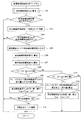
以上説明した本実施例の硫黄被毒回復制御は、ECU29によって図2の硫黄被毒回復制御プログラムに従って次のようにして実行される。
The sulfur poisoning recovery control of the present embodiment described above is executed by the
図2の硫黄被毒回復制御プログラムは、エンジン運転中に所定周期で実行される。本プログラムが起動されると、まずステップ101で、触媒温度推定ルーチン(図示せず)を実行してNOx触媒23の推定触媒温度Tcat を例えば次式により算出する。
The sulfur poisoning recovery control program of FIG. 2 is executed at a predetermined cycle during engine operation. When this program is started, first, in

ここで、入りガスエネルギは、NOx触媒23に流入する単位時間当たりの排出ガスの熱エネルギである。燃料性状によって排出ガスの温度が変化するため、入りガスエネルギも燃料性状によって変化する。入りガス熱容量は、NOx触媒23と熱交換する排出ガスの熱容量である。触媒エネルギは、NOx触媒23のもつ熱エネルギであり、触媒熱容量は、NOx触媒23の熱容量である。反応エネルギは、NOx触媒23での排出ガスのリッチ成分とリーン成分との反応によって発生する熱エネルギである。この反応エネルギは反応量と発熱係数との積によって計算される。この発熱係数は、燃料性状によって変化する。
Here, the incoming gas energy is the thermal energy of the exhaust gas per unit time flowing into the
この推定触媒温度Tcat の算出方法は、上記の方法に限定されず、どの様な方法で行っても良いが、例えばエンジン始動後の排気熱量積算値に基づいて始動後の触媒温度上昇量を推定して、この始動後の触媒温度上昇量を始動当初の触媒温度に加算して現時点の推定触媒温度Tcat を算出する。 The method for calculating the estimated catalyst temperature Tcat is not limited to the above method, and any method may be used. For example, the amount of catalyst temperature increase after starting is estimated based on the integrated value of exhaust heat after starting the engine. Then, the current estimated catalyst temperature Tcat is calculated by adding the amount of increase in the catalyst temperature after the start to the catalyst temperature at the start of the start.
Tcat =始動後の触媒温度上昇量+(始動当初の触媒温度)
=K×(始動後の排気熱量積算値)+(始動当初の触媒温度)
=K×∫(排気温度×排気流量)dt+(始動当初の触媒温度)
Tcat = catalyst temperature increase after start-up + (catalyst temperature at start-up)
= K x (exhaust heat integrated value after start-up) + (catalyst temperature at start-up)
= K x ∫ (exhaust temperature x exhaust flow rate) dt + (starting catalyst temperature)
ここで、Kは、排気熱量による推定触媒温度Tcat の上昇量を算出するための係数である。排気熱量や排気温度は、排気管21のNOx触媒23の上流側に設置した排気温度センサで実測しても良いし、エンジン運転条件から推定するようにしても良い。排気流量は、エアフローメータ14で検出した吸入空気流量から推定すれば良い。
Here, K is a coefficient for calculating the increase amount of the estimated catalyst temperature Tcat due to the exhaust heat amount. The exhaust heat quantity and the exhaust temperature may be measured by an exhaust temperature sensor installed on the upstream side of the
尚、始動後の排気熱量積算値の代わりに、例えば始動後の燃料噴射量積算値又は始動後経過時間に基づいて始動後の触媒温度上昇量を推定するようにしても良い。また、始動当初の触媒温度は、水温センサ27で検出した始動当初の冷却水温から推定しても良いし、冷却水温の他にエンジン停止時間や外気温等も考慮して始動当初の触媒温度を推定するようにしても良い。その他、NOx触媒23の下流側に設置した排気温度センサで検出した排出ガスの温度に基づいて推定触媒温度Tcat を算出しても良い。
上記ステップ101の処理が特許請求の範囲でいう触媒温度推定手段としての役割を果たす。
Instead of the exhaust heat amount integrated value after the start, the catalyst temperature increase amount after the start may be estimated based on the fuel injection amount integrated value after the start or the elapsed time after the start, for example. The initial catalyst temperature may be estimated from the initial cooling water temperature detected by the
The process of
推定触媒温度Tcat の算出後、ステップ102に進み、硫黄被毒回復制御実行条件が成立しているか否かを、例えば次の条件(1),(2) によって判定する。
(1) 前回の硫黄被毒回復制御実行後の積算走行距離又は積算消費燃料量が所定値に達すること(又は硫黄濃度センサ26で検出したNOx触媒23下流側の硫黄濃度が所定値以上であること)
(2) 硫黄被毒回復制御の終了条件が成立していないこと
After calculating the estimated catalyst temperature Tcat, the routine proceeds to step 102 where it is determined, for example, by the following conditions (1) and (2) whether or not the sulfur poisoning recovery control execution condition is satisfied.
(1) The accumulated travel distance or accumulated fuel consumption after execution of the previous sulfur poisoning recovery control reaches a predetermined value (or the sulfur concentration downstream of the
(2) End condition for sulfur poisoning recovery control is not satisfied
ここで、硫黄被毒回復制御の終了条件は、例えば硫黄被毒回復制御の実行時間が硫黄被毒の回復に必要な所定時間を越えたときに硫黄被毒回復制御を終了させるようにしたり、硫黄被毒回復制御の実行中に硫黄濃度センサ26で検出したNOx触媒23下流側の硫黄濃度が所定値以下になったときに、硫黄被毒回復制御を終了させるようにしても良い。
Here, the end condition of the sulfur poisoning recovery control is, for example, to end the sulfur poisoning recovery control when the execution time of the sulfur poisoning recovery control exceeds a predetermined time necessary for the sulfur poisoning recovery, The sulfur poisoning recovery control may be terminated when the sulfur concentration downstream of the
上記2つの条件(1),(2) のいずれか一方でも満たされない条件があれば、硫黄被毒回復制御実行条件が不成立となり、以降の処理を行うことなく本プログラムを終了する。
これに対して、上記2つの条件(1),(2) が両方とも満たされれば、硫黄被毒回復制御実行条件が成立して、ステップ103に進み、NOx触媒23の温度を硫黄被毒回復に適した所定温度範囲内(例えば650〜700℃)に昇温させるNOx触媒昇温制御を実行すると共に、NOx触媒23に吸着された硫黄化合物の脱離反応を促進させるために、NOx触媒23に流入する排出ガスの空燃比をストイキ(理論空燃比)よりリッチ側に制御する。
If there is a condition that does not satisfy one of the two conditions (1) and (2), the sulfur poisoning recovery control execution condition is not satisfied, and the program is terminated without performing the subsequent processing.
On the other hand, if both of the above two conditions (1) and (2) are satisfied, the sulfur poisoning recovery control execution condition is established, and the routine proceeds to step 103 where the temperature of the
この硫黄被毒回復制御(NOx触媒昇温制御+空燃比リッチ制御)は、例えば、燃料噴射量の増量補正と点火時期の遅角補正とを組み合わせて実施しても良いし、排気管21のうちのNOx触媒23の上流側に燃料等のHCを添加するHC添加ノズル(図示せず)を設けて、硫黄被毒回復制御の実行中にNOx触媒23に流入する排出ガスにHC添加ノズルからHCを添加することで、NOx触媒23に流入する排出ガスの空燃比をリッチ化して、NOx触媒23での反応熱を増加させてNOx触媒23を昇温させるようにしても良い。このステップ103の処理が特許請求の範囲でいう硫黄被毒回復制御手段としての役割を果たす。
This sulfur poisoning recovery control (NOx catalyst temperature increase control + air-fuel ratio rich control) may be implemented by combining, for example, fuel injection amount increase correction and ignition timing retardation correction, or the
この後、ステップ104に進み、現在の推定触媒温度Tcat が硫黄脱離開始温度以上(例えば600℃以上)であるか否かを判定し、まだ硫黄脱離開始温度に達していなければ、以降の処理を行うことなく本プログラムを終了する。 Thereafter, the routine proceeds to step 104 where it is determined whether or not the current estimated catalyst temperature Tcat is equal to or higher than the sulfur desorption start temperature (for example, 600 ° C. or higher). Exit this program without processing.
一方、上記ステップ104で、現在の推定触媒温度Tcat が硫黄脱離開始温度以上であると判定されれば、NOx触媒23に吸着された硫黄化合物の脱離反応が発生していると判断して、ステップ105に進み、硫黄濃度センサ26の検出硫黄濃度を読み込み、次のステップ106で、硫黄濃度センサ26の検出硫黄濃度と排出ガス流量とに基づいて検出硫黄脱離速度V1(単位時間当たりの硫黄化合物の脱離量)を算出する。
On the other hand, if it is determined in
この後、ステップ107に進み、エンジン運転状態又は前回の硫黄被毒回復制御実行後の積算走行距離又は積算消費燃料量等に基づいて推定硫黄脱離速度V2を算出する。この際、例えば、前回の硫黄被毒回復制御実行後の積算走行距離又は積算消費燃料量等に基づいてNOx触媒23の硫黄化合物の吸着量を推定し、図3の硫黄脱離速度推定マップ(その1)を参照して、NOx触媒23の硫黄化合物の推定吸着量と推定触媒温度Tcat に応じて推定硫黄脱離速度V2を算出するようにしても良い。図3の硫黄脱離速度推定マップ(その1)の特性は、硫黄化合物吸着量が多くなるほど、硫黄脱離速度が大きくなり、また、触媒温度が高くなるほど、硫黄脱離速度が大きくなるように設定されている。尚、硫黄化合物の推定吸着量は、燃料性状(燃料中の硫黄濃度)に応じて補正するようにしても良い。
Thereafter, the routine proceeds to step 107, where the estimated sulfur desorption speed V2 is calculated based on the engine operating state or the accumulated travel distance or accumulated fuel consumption after the previous execution of sulfur poisoning recovery control. At this time, for example, the sulfur compound adsorption amount of the
また、エンジン運転状態やNOx触媒23の上流側の酸素センサ25の出力等に基づいてNOx触媒23に流入する排出ガスの空燃比を検出し、図4の硫黄脱離速度推定マップ(その2)を参照して、NOx触媒23に流入する排出ガスの空燃比と推定触媒温度Tcat に応じて推定硫黄脱離速度V2を算出するようにしても良い。図4の硫黄脱離速度推定マップ(その2)の特性は、空燃比がリッチになるほど、硫黄脱離速度が大きくなり、また、触媒温度が高くなるほど、硫黄脱離速度が大きくなるように設定されている。
Further, based on the engine operating state, the output of the
以上のようにして、検出硫黄脱離速度V1と推定硫黄脱離速度V2を算出した後、ステップ108に進み、検出硫黄脱離速度V1と推定硫黄脱離速度V2との差(V1−V2)を所定値K1(正の値)と比較して、この差(V1−V2)が所定値K1よりも大きい場合、つまり、検出硫黄脱離速度V1が推定硫黄脱離速度V2と比べて所定値K1以上大きい場合は、推定触媒温度Tcat が実際の触媒温度よりも低い側にずれていて、実際の触媒温度が適正温度よりも高い温度に制御されていると判断して、ステップ109に進み、差(V1−V2)に応じて推定触媒温度Tcat を高い側に補正するための補正量ΔT(正の値)を補正量ΔTマップ(図示せず)により算出する。この補正量ΔTマップは、差(V1−V2)が大きくなるほど、補正量ΔTが大きくなるように設定されている。 After calculating the detected sulfur desorption rate V1 and the estimated sulfur desorption rate V2 as described above, the process proceeds to step 108, and the difference between the detected sulfur desorption rate V1 and the estimated sulfur desorption rate V2 (V1-V2). Is compared with a predetermined value K1 (positive value) and the difference (V1-V2) is larger than the predetermined value K1, that is, the detected sulfur desorption rate V1 is a predetermined value compared with the estimated sulfur desorption rate V2. If it is greater than K1, the estimated catalyst temperature Tcat is shifted to a lower side than the actual catalyst temperature, and it is determined that the actual catalyst temperature is controlled to a temperature higher than the appropriate temperature. A correction amount ΔT (positive value) for correcting the estimated catalyst temperature Tcat to a higher side according to the difference (V1−V2) is calculated from a correction amount ΔT map (not shown). This correction amount ΔT map is set so that the correction amount ΔT increases as the difference (V1−V2) increases.
この後、ステップ110に進み、推定触媒温度Tcat を補正量ΔTだけ高い側に補正する。
Tcat =Tcat +ΔT
Thereafter, the routine proceeds to step 110, where the estimated catalyst temperature Tcat is corrected to the higher side by the correction amount ΔT.
Tcat = Tcat + ΔT
そして、次のステップ111で、硫黄濃度センサ26の検出硫黄濃度(又は検出硫黄脱離速度V1)が所定値K3(硫黄臭が発生し始める硫黄濃度)よりも高いか否かを判定し、検出硫黄濃度(又は検出硫黄脱離速度V1)が所定値K3よりも高ければ、硫黄臭が発生していると判断して、ステップ112に進み、NOx触媒23に流入する排出ガスの空燃比をストイキよりリーン側に制御するように燃料噴射量を減量補正する。このようにすれば、NOx触媒23から流出する排出ガス中の硫黄濃度が高くなり過ぎて硫黄臭が発生し始めたときに、NOx触媒23に流入する排出ガスの空燃比をストイキよりリーン側に変化させることが可能となり、NOx触媒23で排出ガス中のリッチ成分をリーン成分(O2 等)と酸化反応させて、硫黄化合物の脱離反応に必要なリッチ成分を効果的に減少させることができ、硫黄化合物の過剰な脱離反応を抑制して、硫黄化合物の過剰な脱離による硫黄臭を確実に防止できる。上記ステップ111、112の処理が特許請求の範囲でいう消臭制御手段としての役割を果たす。
Then, in the
尚、上記ステップ111で、硫黄濃度センサ26の検出硫黄濃度(又は検出硫黄脱離速度V1)が所定値K3以下と判定されれば、硫黄臭が問題にならないと判断して、そのまま本プログラムを終了する。この場合は、硫黄化合物の脱離反応を促進させるために、空燃比リッチ制御が継続される。
If the detected sulfur concentration (or detected sulfur desorption rate V1) of the
一方、前述したステップ108で、検出硫黄脱離速度V1と推定硫黄脱離速度V2との差(V1−V2)が所定値K1(正の値)以下と判定されれば、ステップ113に進み、この差(V1−V2)を所定値K2(負の値)と比較して、この差(V1−V2)が所定値K2よりも小さい場合(V1−V2<K2の場合)、つまり、検出硫黄脱離速度V1が推定硫黄脱離速度V2と比べて所定値K2以上小さい場合は、推定触媒温度Tcat が実際の触媒温度よりも高い側にずれていて、実際の触媒温度が適正温度よりも低い温度に制御されていると判断して、ステップ114に進み、差(V1−V2)に応じて推定触媒温度Tcat を低い側に補正するための補正量ΔT(負の値)を補正量ΔTマップ(図示せず)により算出する。この補正量ΔTマップは、差(V1−V2)の絶対値が大きくなるほど、補正量ΔTの絶対値が大きくなるように設定されている。
On the other hand, if it is determined in
この後、ステップ115に進み、推定触媒温度Tcat を補正量ΔT(負の値)だけ低い側に補正する。
Tcat =Tcat +ΔT(負の値)
上記ステップ105〜110、113〜115の処理が特許請求の範囲でいう補正手段としての役割を果たす。
Thereafter, the routine proceeds to step 115, where the estimated catalyst temperature Tcat is corrected to the lower side by the correction amount ΔT (negative value).
Tcat = Tcat + ΔT (negative value)
The processes in
以上説明した本実施例によれば、NOx触媒23からの推定硫黄脱離速度V2を図3又は図4の硫黄脱離速度推定マップを用いて算出し、硫黄濃度センサ26の検出硫黄濃度から算出した検出硫黄脱離速度V1を上記推定硫黄脱離速度V2と比較してその比較結果に応じて推定触媒温度Tcat を補正するようにしたので、検出硫黄脱離速度V1から、NOx触媒23の硫黄化合物吸着量やNOx触媒23に流入する排出ガス中の硫黄濃度による影響を排除して、推定触媒温度Tcat を精度良く補正することができる。これにより、硫黄被毒回復制御に用いる推定触媒温度Tcat の精度を向上させて、実際の触媒温度を硫黄被毒回復制御に適した温度範囲内に制御することが可能となり、硫黄被毒回復制御によりNOx触媒23の硫黄被毒を確実に回復させることができると共に、NOx触媒23の過昇温によるNOx触媒23の劣化や硫黄化合物の過剰な脱離による硫黄臭を防止することができる。
According to the present embodiment described above, the estimated sulfur desorption rate V2 from the
また、本実施例では、検出硫黄脱離速度V1と上記推定硫黄脱離速度V2との差に応じて推定触媒温度Tcat の補正量ΔTを変化させるようにしたので、推定触媒温度Tcat をより精度良く補正することができる。 Further, in this embodiment, since the correction amount ΔT of the estimated catalyst temperature Tcat is changed according to the difference between the detected sulfur desorption rate V1 and the estimated sulfur desorption rate V2, the estimated catalyst temperature Tcat is more accurate. It can be corrected well.
但し、本発明は、推定触媒温度Tcat の補正量ΔTを一定値としても良く、この場合でも、上記図2の硫黄被毒回復制御プログラムを所定周期で繰り返し実行することで、推定触媒温度Tcat を精度良く補正することができる。 However, in the present invention, the correction amount ΔT of the estimated catalyst temperature Tcat may be a constant value. Even in this case, the estimated catalyst temperature Tcat can be set by repeatedly executing the sulfur poisoning recovery control program of FIG. Correction can be made with high accuracy.
また、本実施例では、検出硫黄脱離速度V1を推定硫黄脱離速度V2と比較して推定触媒温度Tcat を補正するようにしたが、推定硫黄脱離速度V2と排出ガス流量とに基づいて推定硫黄濃度を算出し、この推定硫黄濃度と硫黄濃度センサ26の検出硫黄濃度とを比較してその比較結果に応じて推定触媒温度Tcat を補正するようにしても良い。或は、推定硫黄濃度又は推定硫黄脱離速度V2を用いずに、硫黄濃度センサ26の検出硫黄濃度又は検出硫黄脱離速度V1のみで推定触媒温度Tcat を補正するようにしても良い。
Further, in this embodiment, the detected sulfur desorption rate V1 is compared with the estimated sulfur desorption rate V2 to correct the estimated catalyst temperature Tcat, but based on the estimated sulfur desorption rate V2 and the exhaust gas flow rate. An estimated sulfur concentration may be calculated, the estimated sulfur concentration may be compared with the detected sulfur concentration of the
また、本発明は、硫黄被毒回復制御の実行中だけでなく、硫黄被毒回復制御を実行していない場合でも、硫黄濃度センサ26の検出硫黄濃度(又は検出硫黄脱離速度V1)が所定値より高くなったときに、硫黄臭が発生していると判断して、NOx触媒23に流入する排出ガスの空燃比をストイキよりリーン側に制御するように燃料噴射量を減量補正するようにしても良い。
Further, according to the present invention, the detected sulfur concentration (or detected sulfur desorption rate V1) of the
その他、本発明は、リーンバーンエンジンの他に、筒内噴射エンジン等、硫黄被毒の問題が発生する触媒(NOx触媒等)を搭載したエンジンに適用して実施できる。 In addition to the lean burn engine, the present invention can be applied to an engine equipped with a catalyst (such as a NOx catalyst) that causes a problem of sulfur poisoning, such as an in-cylinder injection engine.
11…エンジン(内燃機関)、12…吸気管、20…燃料噴射弁、21…排気管(排気通路)、22…三元触媒、23…NOx触媒、24…空燃比センサ、25…酸素センサ、26…硫黄濃度センサ、29…ECU(硫黄被毒回復制御手段,触媒温度推定手段,補正手段,消臭制御手段)
DESCRIPTION OF
Claims (7)
排出ガス中の硫黄化合物による前記触媒の被毒(以下「硫黄被毒」という)を回復させる要求が発生したときに前記触媒温度推定手段で推定した触媒温度に基づいて前記触媒の温度を所定温度範囲内に昇温させる硫黄被毒回復制御を実行する硫黄被毒回復制御手段とを備えた内燃機関の排気浄化制御装置において、
前記排気通路のうちの前記触媒の下流側に、排出ガス中の硫黄化合物の濃度(以下「硫黄濃度」という)を検出する硫黄濃度センサを設置し、
前記触媒温度推定手段は、前記硫黄濃度センサの検出硫黄濃度又はこの検出硫黄濃度から算出した検出硫黄脱離速度に応じて推定触媒温度を補正する補正手段を有することを特徴とする内燃機関の排気浄化制御装置。 Catalyst temperature estimating means for estimating the temperature of the catalyst installed in the exhaust passage of the internal combustion engine;
The temperature of the catalyst is set to a predetermined temperature based on the catalyst temperature estimated by the catalyst temperature estimating means when a request for recovering poisoning of the catalyst by the sulfur compound in the exhaust gas (hereinafter referred to as “sulfur poisoning”) occurs. In an exhaust gas purification control device for an internal combustion engine, comprising sulfur poisoning recovery control means for performing sulfur poisoning recovery control for raising the temperature within a range,
A sulfur concentration sensor for detecting the concentration of sulfur compounds in the exhaust gas (hereinafter referred to as “sulfur concentration”) is installed downstream of the catalyst in the exhaust passage,
The exhaust temperature of the internal combustion engine, wherein the catalyst temperature estimating means includes a correcting means for correcting the estimated catalyst temperature according to the detected sulfur concentration of the sulfur concentration sensor or the detected sulfur desorption rate calculated from the detected sulfur concentration. Purification control device.
前記補正手段は、前記硫黄濃度センサの検出硫黄濃度又はこの検出硫黄濃度から算出した検出硫黄脱離速度を前記硫黄濃度推定手段の推定硫黄濃度又は推定硫黄脱離速度と比較してその比較結果に応じて推定触媒温度を補正することを特徴とする請求項1に記載の内燃機関の排気浄化制御装置。 Estimating the sulfur concentration in the exhaust gas flowing out from the catalyst or the sulfur desorption rate from the catalyst based on the operating state of the internal combustion engine or the cumulative travel distance or cumulative fuel consumption after the previous execution of sulfur poisoning recovery control Equipped with sulfur concentration estimation means,
The correction means compares the detected sulfur concentration of the sulfur concentration sensor or the detected sulfur desorption rate calculated from the detected sulfur concentration with the estimated sulfur concentration or estimated sulfur desorption rate of the sulfur concentration estimating means, and provides a comparison result. The exhaust purification control apparatus for an internal combustion engine according to claim 1, wherein the estimated catalyst temperature is corrected accordingly.
排出ガス中の硫黄化合物の濃度(以下「硫黄濃度」という)を検出する硫黄濃度センサを前記排気通路のうちの前記触媒の下流側に設置し、
前記硫黄濃度センサの検出硫黄濃度又はこの検出硫黄濃度から算出した検出硫黄脱離速度が所定値以上となるときに空燃比をストイキよりリーン側に制御することで排出ガス中の硫黄化合物による臭いを低減する消臭制御手段を備えていることを特徴とする内燃機関の排気浄化制御装置。 In an exhaust gas purification control device for an internal combustion engine in which a catalyst is installed in the exhaust passage of the internal combustion engine,
A sulfur concentration sensor that detects the concentration of sulfur compounds in the exhaust gas (hereinafter referred to as “sulfur concentration”) is installed downstream of the catalyst in the exhaust passage,
When the detected sulfur concentration of the sulfur concentration sensor or the detected sulfur desorption rate calculated from the detected sulfur concentration exceeds a predetermined value, the odor due to the sulfur compound in the exhaust gas is controlled by controlling the air-fuel ratio to the lean side from the stoichiometry. An exhaust purification control apparatus for an internal combustion engine, comprising deodorizing control means for reducing the deodorizing control means.
Priority Applications (1)
| Application Number | Priority Date | Filing Date | Title |
|---|---|---|---|
| JP2007192746A JP2009030459A (en) | 2007-07-25 | 2007-07-25 | Exhaust emission control device of internal combustion engine |
Applications Claiming Priority (1)
| Application Number | Priority Date | Filing Date | Title |
|---|---|---|---|
| JP2007192746A JP2009030459A (en) | 2007-07-25 | 2007-07-25 | Exhaust emission control device of internal combustion engine |
Publications (1)
| Publication Number | Publication Date |
|---|---|
| JP2009030459A true JP2009030459A (en) | 2009-02-12 |
Family
ID=40401241
Family Applications (1)
| Application Number | Title | Priority Date | Filing Date |
|---|---|---|---|
| JP2007192746A Pending JP2009030459A (en) | 2007-07-25 | 2007-07-25 | Exhaust emission control device of internal combustion engine |
Country Status (1)
| Country | Link |
|---|---|
| JP (1) | JP2009030459A (en) |
Cited By (4)
| Publication number | Priority date | Publication date | Assignee | Title |
|---|---|---|---|---|
| JP2010242688A (en) * | 2009-04-08 | 2010-10-28 | Honda Motor Co Ltd | Exhaust gas purification system for internal combustion engine |
| WO2011064900A1 (en) * | 2009-11-26 | 2011-06-03 | トヨタ自動車株式会社 | Sulfur component detection apparatus |
| WO2011142040A1 (en) * | 2010-05-12 | 2011-11-17 | トヨタ自動車株式会社 | Device for detecting sulfur component |
| US9429057B2 (en) | 2013-06-05 | 2016-08-30 | Toyota Jidosha Kabushiki Kaisha | Method and an apparatus for warming a catalyst in an internal combustion engine |
-
2007
- 2007-07-25 JP JP2007192746A patent/JP2009030459A/en active Pending
Cited By (11)
| Publication number | Priority date | Publication date | Assignee | Title |
|---|---|---|---|---|
| JP2010242688A (en) * | 2009-04-08 | 2010-10-28 | Honda Motor Co Ltd | Exhaust gas purification system for internal combustion engine |
| WO2011064900A1 (en) * | 2009-11-26 | 2011-06-03 | トヨタ自動車株式会社 | Sulfur component detection apparatus |
| CN102667457A (en) * | 2009-11-26 | 2012-09-12 | 丰田自动车株式会社 | Sulfur component detection apparatus |
| JP5196015B2 (en) * | 2009-11-26 | 2013-05-15 | トヨタ自動車株式会社 | Sulfur component detector |
| CN102667457B (en) * | 2009-11-26 | 2013-11-06 | 丰田自动车株式会社 | Sulfur component detection apparatus |
| US8621852B2 (en) | 2009-11-26 | 2014-01-07 | Toyota Jidosha Kabushiki Kaisha | Detector for detecting sulfur components |
| WO2011142040A1 (en) * | 2010-05-12 | 2011-11-17 | トヨタ自動車株式会社 | Device for detecting sulfur component |
| CN102869985A (en) * | 2010-05-12 | 2013-01-09 | 丰田自动车株式会社 | Device for detecting sulfur component |
| JP5196016B2 (en) * | 2010-05-12 | 2013-05-15 | トヨタ自動車株式会社 | Sulfur component detector |
| US8555699B2 (en) | 2010-05-12 | 2013-10-15 | Toyota Jidosha Kabushiki Kaisha | Detector for detecting sulfur components |
| US9429057B2 (en) | 2013-06-05 | 2016-08-30 | Toyota Jidosha Kabushiki Kaisha | Method and an apparatus for warming a catalyst in an internal combustion engine |
Similar Documents
| Publication | Publication Date | Title |
|---|---|---|
| JP3528739B2 (en) | Engine exhaust purification device | |
| US10316716B2 (en) | Exhaust purification system and method for restoring NOx purification capacity | |
| JP4305643B2 (en) | Exhaust gas purification device for internal combustion engine | |
| JP2010185325A (en) | DETERIORATION DIAGNOSIS DEVICE FOR NOx CATALYST | |
| JP4314636B2 (en) | Air-fuel ratio control device for internal combustion engine | |
| EP3266999B1 (en) | Exhaust purification system and catalyst regeneration method | |
| JP5786943B2 (en) | Exhaust gas purification device for internal combustion engine | |
| JP2003314350A (en) | Exhaust gas purifying device of internal combustion engine | |
| JP2009030459A (en) | Exhaust emission control device of internal combustion engine | |
| JP4259361B2 (en) | Exhaust gas purification device for internal combustion engine | |
| WO2007069780A1 (en) | Exhaust gas purification system for internal combustion engine | |
| JP4561656B2 (en) | Catalyst temperature estimation device for internal combustion engine | |
| JP2000110553A (en) | Exhaust gas emission control device of internal combustion engine | |
| JP4389141B2 (en) | Exhaust gas purification device for internal combustion engine | |
| JP4890209B2 (en) | Exhaust gas purification device for internal combustion engine | |
| JP4366976B2 (en) | Exhaust gas sensor abnormality detection device | |
| JP4032840B2 (en) | Exhaust gas purification device for internal combustion engine | |
| JP2015121118A (en) | Exhaust gas purification device for internal combustion engine | |
| JP2003336538A (en) | Exhaust gas purification device for internal combustion engine | |
| JP2008095603A (en) | Exhaust gas purification device for internal combustion engine | |
| JP5093079B2 (en) | Engine exhaust purification system | |
| JP4289133B2 (en) | Air-fuel ratio control device for internal combustion engine | |
| JP4422398B2 (en) | Exhaust gas purification device for internal combustion engine | |
| JP5093134B2 (en) | Exhaust gas purification device for internal combustion engine | |
| JP5169671B2 (en) | Engine exhaust purification system |