JP2009001765A - Adhesive composition, circuit connection structure, and semiconductor device - Google Patents
Adhesive composition, circuit connection structure, and semiconductor device Download PDFInfo
- Publication number
- JP2009001765A JP2009001765A JP2007229196A JP2007229196A JP2009001765A JP 2009001765 A JP2009001765 A JP 2009001765A JP 2007229196 A JP2007229196 A JP 2007229196A JP 2007229196 A JP2007229196 A JP 2007229196A JP 2009001765 A JP2009001765 A JP 2009001765A
- Authority
- JP
- Japan
- Prior art keywords
- circuit
- adhesive composition
- adhesive
- film
- meth
- Prior art date
- Legal status (The legal status is an assumption and is not a legal conclusion. Google has not performed a legal analysis and makes no representation as to the accuracy of the status listed.)
- Granted
Links
- 0 CC1(C(*)=CC(C2(c3ccccc3-c3ccccc23)c(cc2*)ccc2OCCO*CC(COC(C(*)=C)=O)O)=CC1)O*CCOCC(COC(C(*)=C)=O)O Chemical compound CC1(C(*)=CC(C2(c3ccccc3-c3ccccc23)c(cc2*)ccc2OCCO*CC(COC(C(*)=C)=O)O)=CC1)O*CCOCC(COC(C(*)=C)=O)O 0.000 description 1
Images


Classifications
-
- H10W72/07251—
-
- H10W72/073—
-
- H10W72/074—
-
- H10W72/20—
-
- H10W72/325—
-
- H10W72/352—
-
- H10W72/354—
Landscapes
- Wire Bonding (AREA)
- Adhesive Tapes (AREA)
- Adhesives Or Adhesive Processes (AREA)
Abstract
【課題】低温かつ短時間の硬化条件においても優れた接着強度を得ることができ、且つ、信頼性試験(例えば、85℃、85%RH放置)後においても優れた性能を維持することができ、更に貯蔵安定性にも優れた接着剤組成物を提供すること。
【解決手段】 (a)同一分子内にウレタン結合及びエステル結合を有する熱可塑性樹脂と、(b)ラジカル重合性化合物と、(c)ラジカル重合開始剤と、を含有する接着剤組成物であって、上記(a)熱可塑性樹脂を2種類以上含有し、且つ、少なくとも1種の上記(a)熱可塑性樹脂のガラス転移温度が40℃以下であることを特徴とする接着剤組成物。
【選択図】なしIt is possible to obtain excellent adhesive strength even under low temperature and short time curing conditions, and to maintain excellent performance even after a reliability test (for example, left at 85 ° C. and 85% RH). The present invention also provides an adhesive composition having excellent storage stability.
An adhesive composition containing (a) a thermoplastic resin having a urethane bond and an ester bond in the same molecule, (b) a radical polymerizable compound, and (c) a radical polymerization initiator. The adhesive composition is characterized in that it contains two or more types of the above-mentioned (a) thermoplastic resins, and the glass transition temperature of at least one of the above-mentioned (a) thermoplastic resins is 40 ° C. or lower.
[Selection figure] None
Description
本発明は、接着剤組成物、回路接続構造体及び半導体装置に関する。 The present invention relates to an adhesive composition, a circuit connection structure, and a semiconductor device.
半導体素子及び液晶表示素子において、素子中の種々の部材を結合させる目的で従来から種々の接着剤組成物が使用されている。接着剤組成物に要求される特性は、接着性をはじめとして、耐熱性、高温高湿状態における信頼性等、多岐に渡る。 2. Description of the Related Art Various adhesive compositions have been conventionally used in semiconductor elements and liquid crystal display elements for the purpose of bonding various members in the elements. The properties required for the adhesive composition are diverse, including adhesiveness, heat resistance, reliability in a high temperature and high humidity state, and the like.
また、接着に使用される被着体には、プリント配線板、ポリイミド等の有機基材をはじめ、銅、アルミニウム等の金属や、ITO、SiN、SiO2等の多種多様な表面状態を有する基材が用いられる。そのため、接着剤組成物は、各被着体にあわせた分子設計が必要である。 In addition, the adherends used for bonding include printed wiring boards, organic substrates such as polyimide, metals such as copper and aluminum, and substrates having various surface states such as ITO, SiN, and SiO 2. A material is used. Therefore, the adhesive composition needs to have a molecular design tailored to each adherend.
従来から、半導体素子や液晶表示素子用の接着剤組成物としては、高接着性でかつ高信頼性を示すエポキシ樹脂等の熱硬化性樹脂が用いられてきた(例えば、特許文献1参照)。かかる接着剤組成物の構成成分としては、エポキシ樹脂、エポキシ樹脂と反応性を有するフェノール樹脂などの硬化剤、エポキシ樹脂と硬化剤との反応を促進する熱潜在性触媒が一般に用いられている。このうち熱潜在性触媒は、硬化温度及び硬化速度を決定する重要な因子となっており、室温での貯蔵安定性と加熱時の硬化速度の観点から種々の化合物が用いられてきた。このような接着剤組成物は、170〜250℃の温度で1〜3時間熱硬化することにより、所望の接着が得られる。 Conventionally, thermosetting resins such as epoxy resins having high adhesion and high reliability have been used as adhesive compositions for semiconductor elements and liquid crystal display elements (for example, see Patent Document 1). As a component of such an adhesive composition, a curing agent such as an epoxy resin, a phenol resin having reactivity with the epoxy resin, and a thermal latent catalyst that accelerates the reaction between the epoxy resin and the curing agent are generally used. Among these, the heat latent catalyst is an important factor for determining the curing temperature and the curing rate, and various compounds have been used from the viewpoints of storage stability at room temperature and curing rate during heating. Such an adhesive composition can obtain desired adhesion by thermosetting at a temperature of 170 to 250 ° C. for 1 to 3 hours.
しかしながら、最近の半導体素子の高集積化、液晶素子の高精細化に伴い、素子間及び配線間ピッチが狭小化し、硬化時の加熱によって、周辺部材に悪影響を及ぼす恐れが出てきた。 However, with the recent high integration of semiconductor elements and high definition of liquid crystal elements, the pitch between elements and wirings has narrowed, and there has been a risk of adversely affecting peripheral members due to heating during curing.
さらに、低コスト化のためには、スループットを向上させる必要性があり、より低温でかつ短時間で硬化する接着剤組成物、換言すれば「低温速硬化」の接着剤組成物が要求されている。接着剤組成物の低温速硬化を達成するために、例えば、活性化エネルギーの低い熱潜在性触媒が使用されることもあるが、その場合、室温付近での貯蔵安定性を兼備することが非常に難しいことが知られている。 Furthermore, in order to reduce the cost, there is a need to improve the throughput, and there is a demand for an adhesive composition that cures at a lower temperature and in a shorter time, in other words, an adhesive composition that is “low temperature fast cure”. Yes. In order to achieve low-temperature rapid curing of the adhesive composition, for example, a thermal latent catalyst having a low activation energy may be used, and in that case, it is extremely desirable to combine storage stability near room temperature. It is known to be difficult.
また、低温速硬化の要求に応える接着剤組成物として、最近、アクリレート誘導体やメタクリレート誘導体(以下、「(メタ)アクリレート誘導体」という)とラジカル重合開始剤である過酸化物とを併用した、ラジカル硬化型接着剤が注目されている。このような接着剤組成物は、反応活性種であるラジカルが反応性に富むため、短時間硬化が可能である(例えば、特許文献2参照)。 In addition, as an adhesive composition that meets the requirements for low-temperature rapid curing, recently, radicals that use acrylate derivatives and methacrylate derivatives (hereinafter referred to as “(meth) acrylate derivatives”) and peroxides as radical polymerization initiators in combination. A curable adhesive is drawing attention. Such an adhesive composition can be cured in a short time because radicals that are reactive species are highly reactive (see, for example, Patent Document 2).
一方、ラジカル硬化型接着剤を用いた場合に接着強度を向上するために、シリコン変性ポリイミド樹脂やポリエステルウレタン樹脂といった特定の官能基を有する熱可塑性樹脂が用いる方法も提案されている(例えば、特許文献3及び4参照)。 On the other hand, a method using a thermoplastic resin having a specific functional group such as a silicon-modified polyimide resin or a polyester urethane resin has been proposed in order to improve the adhesive strength when using a radical curable adhesive (for example, patents). References 3 and 4).
しかしながら、上記特許文献2に記載されたラジカル硬化型接着剤は、接着強度が必ずしも十分ではないという問題がある。また、ラジカル重合性化合物と過酸化物とを併用した場合、十分な低温速硬化を達成するためには活性化エネルギーの低い過酸化物を使用する必要があり、室温付近での貯蔵安定性が低下することがある。また、接着強度の十分な耐湿信頼性を確保することが困難である。
However, the radical curable adhesive described in
また、上記特許文献3及び4に示されるような特定の官能基を有する熱可塑性樹脂を用いた場合であっても、低温で硬化させた場合、ラジカル重合性化合物の反応が十分に進まず、高い接着強度を示すことが困難である。 Further, even when a thermoplastic resin having a specific functional group as shown in Patent Documents 3 and 4 is used, when cured at a low temperature, the reaction of the radical polymerizable compound does not sufficiently proceed, It is difficult to show high adhesive strength.
本発明は上記従来技術の有する課題に鑑みてなされたものであり、低温かつ短時間の硬化条件においても優れた接着強度を得ることができ、且つ、信頼性試験(例えば、85℃、85%RH放置)後においても優れた性能を維持することができ、更に貯蔵安定性にも優れた接着剤組成物、この接着剤組成物を用いた回路接続構造体及び半導体装置を提供することを目的とする。 The present invention has been made in view of the above-described problems of the prior art, and can provide excellent adhesive strength even under low-temperature and short-time curing conditions. In addition, a reliability test (for example, 85 ° C., 85% An object of the present invention is to provide an adhesive composition that can maintain excellent performance even after RH leaving) and also has excellent storage stability, and a circuit connection structure and a semiconductor device using the adhesive composition. And
上記目的を達成するために、本発明は、(a)同一分子内にウレタン結合及びエステル結合を有する熱可塑性樹脂と、(b)ラジカル重合性化合物と、(c)ラジカル重合開始剤と、を含有する接着剤組成物であって、上記(a)熱可塑性樹脂を2種類以上含有し、且つ、少なくとも1種の上記(a)熱可塑性樹脂のガラス転移温度が40℃以下であることを特徴とする接着剤組成物を提供する。 In order to achieve the above object, the present invention comprises (a) a thermoplastic resin having a urethane bond and an ester bond in the same molecule, (b) a radical polymerizable compound, and (c) a radical polymerization initiator. An adhesive composition containing two or more types of the above-mentioned (a) thermoplastic resin, and at least one of the above-mentioned (a) thermoplastic resins has a glass transition temperature of 40 ° C. or lower. An adhesive composition is provided.
かかる接着剤組成物によれば、上記構成を有することにより、低温かつ短時間の硬化条件においても優れた接着強度を得ることができ、且つ、信頼性試験(例えば、85℃、85%RH放置)後においても優れた性能を維持することができ、更に、優れた貯蔵安定性を得ることができる。特に、ガラス転移温度が40℃以下の(a)熱可塑性樹脂を少なくとも1種含有することで、接続直後のみならず信頼性試験後においても優れた接着強度を得ることができる。 According to such an adhesive composition, by having the above-described configuration, excellent adhesive strength can be obtained even under low temperature and short time curing conditions, and a reliability test (for example, left at 85 ° C. and 85% RH). ) Excellent performance can be maintained afterwards, and excellent storage stability can be obtained. In particular, by containing at least one thermoplastic resin (a) having a glass transition temperature of 40 ° C. or lower, excellent adhesive strength can be obtained not only immediately after connection but also after a reliability test.
本発明の接着剤組成物において、少なくとも1種の上記(a)熱可塑性樹脂のガラス転移温度が、60℃以上であることが好ましい。ガラス転移温度が60℃以上である(a)熱可塑性樹脂を、ガラス転移温度が40℃以下である(a)熱可塑性樹脂と併用することにより、接着剤組成物の耐熱性をより高度に確保することができる。 In the adhesive composition of the present invention, the glass transition temperature of at least one of the above-mentioned (a) thermoplastic resins is preferably 60 ° C. or higher. (A) A thermoplastic resin having a glass transition temperature of 60 ° C. or higher and (a) a thermoplastic resin having a glass transition temperature of 40 ° C. or lower in combination with (a) a thermoplastic resin to further secure the heat resistance of the adhesive composition. can do.
また、本発明の接着剤組成物は、さらに(d)分子内に1つ以上のリン酸基を有するビニル化合物を含有することが好ましい。これにより、低温かつ短時間の硬化条件において、より優れた接着強度を得ることができる。 The adhesive composition of the present invention preferably further contains (d) a vinyl compound having one or more phosphate groups in the molecule. Thereby, more excellent adhesive strength can be obtained under low temperature and short time curing conditions.
また、本発明の接着剤組成物は、さらに(e)導電性粒子を含有することが好ましい。これにより、接着剤組成物に導電性又は異方導電性を付与することができるため、接着剤組成物を、回路電極を有する回路部材同士の接続用途等により好適に使用することが可能となる。また、上記接着剤組成物を介して電気的に接続した回路電極間の接続抵抗を十分に低減することができる。 Moreover, it is preferable that the adhesive composition of this invention contains (e) electroconductive particle further. Thereby, since electroconductivity or anisotropic conductivity can be provided to an adhesive composition, it becomes possible to use an adhesive composition suitably for the connection use etc. of the circuit members which have a circuit electrode. . Moreover, the connection resistance between the circuit electrodes electrically connected through the adhesive composition can be sufficiently reduced.
本発明はまた、対向配置された一対の回路部材と、上記一対の回路部材の間に設けられ、上記一対の回路部材が有する回路電極同士が電気的に接続されるように回路部材同士を接着する接続部材と、を備え、上記接続部材が、上記本発明の接着剤組成物の硬化物からなるものである、回路接続構造体を提供する。 The present invention also provides a pair of circuit members disposed opposite to each other, and the circuit members provided between the pair of circuit members so that the circuit electrodes of the pair of circuit members are electrically connected to each other. A circuit connection structure, wherein the connection member is made of a cured product of the adhesive composition of the present invention.
かかる回路接続構造体は、一対の回路部材を接続する接続部材が上記本発明の接着剤組成物の硬化物により構成されているため、回路部材間の接着強度を十分に高くすることができ、且つ、高温高湿環境下に長期間おかれた場合であっても接着強度の低下を十分に抑制することができる。 In such a circuit connection structure, since the connection member for connecting the pair of circuit members is composed of the cured product of the adhesive composition of the present invention, the adhesive strength between the circuit members can be sufficiently increased. And even if it is a case where it is left for a long time in a high-temperature, high-humidity environment, the fall of adhesive strength can fully be suppressed.
本発明は更に、半導体素子と、上記半導体素子を搭載する基板と、上記半導体素子及び上記基板間に設けられ、上記半導体素子及び上記基板を電気的に接続するとともに接着する接続部材と、を備え、上記接続部材が、上記本発明の接着剤組成物の硬化物からなるものである、半導体装置を提供する。 The present invention further includes a semiconductor element, a substrate on which the semiconductor element is mounted, and a connection member that is provided between the semiconductor element and the substrate and electrically connects and bonds the semiconductor element and the substrate. A semiconductor device in which the connecting member is made of a cured product of the adhesive composition of the present invention is provided.
かかる半導体装置は、半導体素子と基板とを接続する接続部材が上記本発明の接着剤組成物の硬化物により構成されているため、半導体素子と基板との間の接着強度を十分に高くすることができ、且つ、高温高湿環境下に長期間おかれた場合であっても接着強度の低下を十分に抑制することができる。 In such a semiconductor device, since the connecting member for connecting the semiconductor element and the substrate is made of the cured product of the adhesive composition of the present invention, the bonding strength between the semiconductor element and the substrate is sufficiently increased. Even if it is a case where it is left for a long time in a high-temperature and high-humidity environment, it is possible to sufficiently suppress the decrease in the adhesive strength.
本発明によれば、低温かつ短時間の硬化条件においても優れた接着強度を得ることができ、且つ、信頼性試験(例えば、85℃、85%RH放置)後においても優れた性能を維持することができ、更に貯蔵安定性にも優れた接着剤組成物、この接着剤組成物を用いた回路接続構造体及び半導体装置を提供することができる。 According to the present invention, excellent adhesive strength can be obtained even under low-temperature and short-time curing conditions, and excellent performance can be maintained even after a reliability test (for example, at 85 ° C. and 85% RH). In addition, it is possible to provide an adhesive composition excellent in storage stability, a circuit connection structure using the adhesive composition, and a semiconductor device.
以下、場合により図面を参照しつつ、本発明の好適な実施形態について詳細に説明する。なお、図面中、同一又は相当部分には同一符号を付し、重複する説明は省略する。また、本発明において、(メタ)アクリル酸とはアクリル酸又はそれに対応するメタクリル酸を示し、(メタ)アクリレートとはアクリレート又はそれに対応するメタクリレートを意味し、(メタ)アクリロイル基とはアクリロイル基又はメタクリロイル基を意味する。 Hereinafter, preferred embodiments of the present invention will be described in detail with reference to the drawings as the case may be. In the drawings, the same or corresponding parts are denoted by the same reference numerals, and redundant description is omitted. In the present invention, (meth) acrylic acid indicates acrylic acid or methacrylic acid corresponding thereto, (meth) acrylate means acrylate or methacrylate corresponding thereto, and (meth) acryloyl group means acryloyl group or Means a methacryloyl group;
本発明の接着剤組成物は、(a)同一分子内にウレタン結合及びエステル結合を有する熱可塑性樹脂と、(b)ラジカル重合性化合物と、(c)ラジカル重合開始剤と、を含有する接着剤組成物であって、上記(a)熱可塑性樹脂を2種類以上含有し、且つ、少なくとも1種の上記(a)熱可塑性樹脂のガラス転移温度が40℃以下であることを特徴とするものである。以下、各成分について詳細に説明する。 The adhesive composition of the present invention is an adhesive containing (a) a thermoplastic resin having a urethane bond and an ester bond in the same molecule, (b) a radical polymerizable compound, and (c) a radical polymerization initiator. A composition comprising two or more types of the above-mentioned (a) thermoplastic resin, and at least one of the above-mentioned (a) thermoplastic resins has a glass transition temperature of 40 ° C. or lower. It is. Hereinafter, each component will be described in detail.
本発明で用いる(a)同一分子内にウレタン結合及びエステル結合を有する熱可塑性樹脂(以下、場合により「ポリエステルウレタン樹脂」という)は、例えば、ポリエステルポリオールとジイソシアネートとの反応により得ることができる。(a)ポリエステルウレタン樹脂の重量平均分子量としては、5,000〜150,000が好ましく、10,000〜80,000がより好ましい。この値が5,000未満では、フィルム状で用いる場合にフィルム形成性が劣る傾向があり、また150,000を超えると他の成分との相溶性が悪くなる傾向がある。 The thermoplastic resin (a) having a urethane bond and an ester bond in the same molecule (hereinafter sometimes referred to as “polyester urethane resin”) used in the present invention can be obtained, for example, by a reaction between a polyester polyol and a diisocyanate. (A) As a weight average molecular weight of a polyester urethane resin, 5,000-150,000 are preferable and 10,000-80,000 are more preferable. If this value is less than 5,000, the film formability tends to be inferior when used in the form of a film, and if it exceeds 150,000, the compatibility with other components tends to be poor.
ポリエステルウレタン樹脂の合成に用いられるポリエステルポリオールは、例えば、ジカルボン酸とジオールとの反応により得ることができる。ジカルボン酸としては、具体的にはテレフタル酸、イソフタル酸、フタル酸、アジピン酸、セバチン酸などが挙げられる。また、ジオールとしては、具体的にはエチレングリコール、プロピレングリコール、1,4−ブタンジオール、1,6−ヘキサンジオール、ネオペンチルグリコール、トリエチレングリコールなどが挙げられる。これらは1種を単独で又は複数を混合して用いることができる。 The polyester polyol used for the synthesis | combination of a polyester urethane resin can be obtained by reaction of dicarboxylic acid and diol, for example. Specific examples of the dicarboxylic acid include terephthalic acid, isophthalic acid, phthalic acid, adipic acid, and sebacic acid. Specific examples of the diol include ethylene glycol, propylene glycol, 1,4-butanediol, 1,6-hexanediol, neopentyl glycol, triethylene glycol, and the like. These can be used alone or in combination.
また、ジイソシアネート化合物は、具体的には2,4−トリレンジイソシアネート、3,3’−ジメチル−4,4’−ビフェニレンジイソシアネート、1、6−ヘキサメチレンジイソシアネート、1,3−フェニレンジイソシアネート、1,4−フェニレンジイソシアネート、ナフタレン−1,5−ジイソシアネート、3,3’−ジメチルジフェニルメタン−4,4’−ジイソシアネート、4,4’−メチレンビス(シクロヘキシルイソシアネート)、イソホロンジイソシアネート、4,4’−ジフェニルメタンジイソシアネート、ジシクロヘキシルメタン−4,4’−ジイソシアネート、トルエン−2,6−ジイソシアネート、トルエン−2,4−ジイソシアネート、トリエチルヘキサメチレンジイソシアネート、m−キシレンジイソシアネートなどが挙げられる。これらは1種を単独で又は複数を混合して用いることができる。 Further, the diisocyanate compound specifically includes 2,4-tolylene diisocyanate, 3,3′-dimethyl-4,4′-biphenylene diisocyanate, 1,6-hexamethylene diisocyanate, 1,3-phenylene diisocyanate, 1, 4-phenylene diisocyanate, naphthalene-1,5-diisocyanate, 3,3′-dimethyldiphenylmethane-4,4′-diisocyanate, 4,4′-methylenebis (cyclohexyl isocyanate), isophorone diisocyanate, 4,4′-diphenylmethane diisocyanate, Dicyclohexylmethane-4,4′-diisocyanate, toluene-2,6-diisocyanate, toluene-2,4-diisocyanate, triethylhexamethylene diisocyanate, m-xylene diisocyanate Such as over doors and the like. These can be used alone or in combination.
本発明の接着剤組成物は、2種類以上の(a)ポリエステルウレタン樹脂を含み、少なくとも1種のガラス転移温度が40℃以下であることを特徴とするものである。ガラス転移温度が40℃以下の(a)ポリエステルウレタン樹脂を含まない場合、耐湿試験後に接着強度が著しく低下する。 The adhesive composition of the present invention comprises two or more types of (a) polyester urethane resins, and has at least one glass transition temperature of 40 ° C. or lower. When the (a) polyester urethane resin having a glass transition temperature of 40 ° C. or lower is not included, the adhesive strength is significantly lowered after the moisture resistance test.
ガラス転移温度が40℃以下の(a)ポリエステルウレタン樹脂のガラス転移温度は、0〜35℃であることがより好ましく、5〜30℃であることが特に好ましい。ガラス転移温度が0℃未満であると、接着剤組成物の耐熱性が著しく低下する傾向がある。 The glass transition temperature of the (a) polyester urethane resin having a glass transition temperature of 40 ° C. or lower is more preferably 0 to 35 ° C., and particularly preferably 5 to 30 ° C. When the glass transition temperature is less than 0 ° C., the heat resistance of the adhesive composition tends to be remarkably lowered.
ここで、2種類以上の(a)ポリエステルウレタン樹脂全体に占める、ガラス転移温度が40℃以下の(a)ポリエステルウレタン樹脂の比率は、(a)ポリエステルウレタン樹脂全体の量を基準として、5〜60質量%であることが好ましく、10〜40質量%であることがより好ましい。この比率が5質量%未満であると、耐湿試験後に接着強度が低下しやすい傾向があり、60質量%を超えると、接着剤組成物の耐熱性が低下する傾向がある。 Here, the ratio of the (a) polyester urethane resin having a glass transition temperature of 40 ° C. or less in the entire two or more types of (a) polyester urethane resins is 5 to 5% on the basis of the amount of the whole (a) polyester urethane resin. It is preferably 60% by mass, more preferably 10 to 40% by mass. If this ratio is less than 5% by mass, the adhesive strength tends to decrease after the moisture resistance test, and if it exceeds 60% by mass, the heat resistance of the adhesive composition tends to decrease.
また、本発明の接着剤組成物は、2種類以上の(a)ポリエステルウレタン樹脂のうち、少なくとも1種の(a)ポリエステルウレタン樹脂のガラス転移温度が60℃以上であることが好ましい。ガラス転移温度が60℃以上の(a)ポリエステルウレタン樹脂を含まない場合、十分な耐熱性の確保が困難となる傾向がある。 Moreover, it is preferable that the glass transition temperature of at least 1 type (a) polyester urethane resin is 60 degreeC or more among the 2 or more types (a) polyester urethane resins of the adhesive composition of this invention. When the (a) polyester urethane resin having a glass transition temperature of 60 ° C. or higher is not included, it tends to be difficult to ensure sufficient heat resistance.
ガラス転移温度が60℃以上の(a)ポリエステルウレタン樹脂のガラス転移温度は、60〜90℃であることがより好ましく、65〜85℃であることが特に好ましい。ガラス転移温度が90℃を超えると、接着剤組成物の流動性が低下する傾向がある。 The glass transition temperature of the (a) polyester urethane resin having a glass transition temperature of 60 ° C. or higher is more preferably 60 to 90 ° C., and particularly preferably 65 to 85 ° C. When the glass transition temperature exceeds 90 ° C., the fluidity of the adhesive composition tends to decrease.
ここで、2種類以上の(a)ポリエステルウレタン樹脂全体に占める、ガラス転移温度が60℃以上の(a)ポリエステルウレタン樹脂の比率は、(a)ポリエステルウレタン樹脂全体の量を基準として、40〜95質量%であることが好ましく、60〜90質量%であることがより好ましい。この比率が40質量%未満であると、十分な耐熱性の確保が困難となる傾向があり、95質量%を超えると、耐湿試験後に接着強度が低下する傾向がある。 Here, the ratio of the (a) polyester urethane resin having a glass transition temperature of 60 ° C. or higher in the entire two or more types of (a) polyester urethane resins is 40 to 40% on the basis of the amount of the whole (a) polyester urethane resins. It is preferably 95% by mass, and more preferably 60 to 90% by mass. If this ratio is less than 40% by mass, it tends to be difficult to ensure sufficient heat resistance, and if it exceeds 95% by mass, the adhesive strength tends to decrease after the moisture resistance test.
本発明の接着剤組成物において、2種類以上の(a)ポリエステルウレタン樹脂全体の含有量は、接着剤組成物全量を基準として、2.5〜60質量%であることが好ましく、5〜55質量%であることがより好ましい。この添加量が2.5質量%未満では耐湿試験後に接着力が低下する傾向があり、60質量%を超えると流動性が低下する恐れがある。 In the adhesive composition of the present invention, the total content of two or more types of (a) polyester urethane resins is preferably 2.5 to 60% by mass based on the total amount of the adhesive composition, and is preferably 5 to 55%. More preferably, it is mass%. If the amount added is less than 2.5% by mass, the adhesive strength tends to decrease after the moisture resistance test, and if it exceeds 60% by mass, the fluidity may decrease.
本発明において用いる(b)ラジカル重合性化合物としては、特に制限無く公知のものを使用することができる。また、(b)ラジカル重合性化合物は、モノマー、オリゴマーいずれの状態でも使用することができ、モノマーとオリゴマーとを混合して用いてもよい。 As the radically polymerizable compound (b) used in the present invention, known compounds can be used without any particular limitation. The (b) radical polymerizable compound can be used in either a monomer or oligomer state, and a monomer and an oligomer may be mixed and used.
(b)ラジカル重合性化合物として具体的には、エポキシ(メタ)アクリレートオリゴマー、ウレタン(メタ)アクリレートオリゴマー、ポリエーテル(メタ)アクリレートオリゴマー、ポリエステル(メタ)アクリレートオリゴマー等のオリゴマー、トリメチロールプロパントリ(メタ)アクリレート、ポリエチレングリコールジ(メタ)アクリレート、ポリアルキレングリコールジ(メタ)アクリレート、ジシクロペンテニル(メタ)アクリレート、ジシクロペンテニロキシエチル(メタ)アクリレート、ネオペンチルグリコールジ(メタ)アクリレート、ジペンタエリスリトールヘキサ(メタ)アクリレート、イソシアヌル酸変性2官能(メタ)アクリレート、イソシアヌル酸変性3官能(メタ)アクリレート、ビスフェノールフルオレンジグリシジルエーテルのグリシジル基に(メタ)アクリル酸を付加させたエポキシ(メタ)アクリレート、ビスフェノールフルオレンジグリシジルエーテルのグリシジル基にエチレングリコールやプロピレングリコールを付加させた化合物に(メタ)アクリロイルオキシ基を導入した化合物、下記一般式(1)及び(2)で示される化合物等が挙げられる。これらの化合物は、1種を単独で又は2種以上を混合して用いることができる。 (B) Specific examples of the radical polymerizable compound include epoxy (meth) acrylate oligomers, urethane (meth) acrylate oligomers, polyether (meth) acrylate oligomers, polyester (meth) acrylate oligomers, trimethylolpropane tri ( (Meth) acrylate, polyethylene glycol di (meth) acrylate, polyalkylene glycol di (meth) acrylate, dicyclopentenyl (meth) acrylate, dicyclopentenyloxyethyl (meth) acrylate, neopentyl glycol di (meth) acrylate, di Pentaerythritol hexa (meth) acrylate, isocyanuric acid modified bifunctional (meth) acrylate, isocyanuric acid modified trifunctional (meth) acrylate, bisphenol fluor (Meth) acryloyloxy group is introduced into compounds in which ethylene glycol or propylene glycol is added to the glycidyl group of bisphenol fluorenediglycidyl ether. And the compounds represented by the following general formulas (1) and (2). These compounds can be used individually by 1 type or in mixture of 2 or more types.
[式中、R1及びR2は各々独立に水素原子又はメチル基を示し、k及びlは各々独立に1〜8の整数を示す。なお、式中、R1同士及びR2同士はそれぞれ同一でも異なっていてもよい。]
[Wherein, R 1 and R 2 each independently represent a hydrogen atom or a methyl group, and k and l each independently represent an integer of 1 to 8. In the formula, R 1 and R 2 may be the same or different. ]
[式中、R3及びR4は各々独立に水素原子又はメチル基を示し、m及びnは各々独立に0〜8の整数を示す。なお、式中、R3同士及びR4同士はそれぞれ同一でも異なっていてもよい。]
[Wherein, R 3 and R 4 each independently represent a hydrogen atom or a methyl group, and m and n each independently represents an integer of 0 to 8. In the formula, R 3 and R 4 may be the same or different. ]
本発明の接着剤組成物は、(b)ラジカル重合性化合物として、分子内に2つ以上の(メタ)アクリロイル基を有する化合物を含むことが好ましい。 The adhesive composition of the present invention preferably contains a compound having two or more (meth) acryloyl groups in the molecule as the radically polymerizable compound (b).
また、本発明の接着剤組成物は、流動性の調節を目的に、(b)ラジカル重合性化合物として、単官能(メタ)アクリレートを含んでいてもよい。単官能(メタ)アクリレートとしては、例えば、ペンタエリスリトール(メタ)アクリレート、2−シアノエチル(メタ)アクリレート、シクロヘキシル(メタ)アクリレート、ジシクロペンテニル(メタ)アクリレート、ジシクロペンテニロキシエチル(メタ)アクリレート、2−(2−エトキシエトキシ)エチル(メタ)アクリレート、2−エトキシエチル(メタ)アクリレート、2−エチルヘキシル(メタ)アクリレート、n−ヘキシル(メタ)アクリレート、2−ヒドロキシエチル(メタ)アクリレート、ヒドロキシプロピル(メタ)アクリレート、イソボルニル(メタ)アクリレート、イソデシル(メタ)アクリレート、イソオクチル(メタ)アクリレート、n−ラウリル(メタ)アクリレート、2−メトキシエチル(メタ)アクリレート、2−フェノキシエチル(メタ)アクリレート、テトラヒドロフルフリール(メタ)アクリレート、2−(メタ)アクリロイロキシエチルホスフェート、N,N−ジメチルアミノエチル(メタ)アクリレート、N,N−ジメチルアミノプロピル(メタ)アクリレート、(メタ)アクリロイルモルホリン等が挙げられる。これらの化合物は1種を単独で使用する以外に、必要に応じて複数の化合物を混合して用いてもよい。 Moreover, the adhesive composition of this invention may contain monofunctional (meth) acrylate as a (b) radically polymerizable compound for the purpose of adjustment of fluidity | liquidity. Examples of monofunctional (meth) acrylates include pentaerythritol (meth) acrylate, 2-cyanoethyl (meth) acrylate, cyclohexyl (meth) acrylate, dicyclopentenyl (meth) acrylate, and dicyclopentenyloxyethyl (meth) acrylate. 2- (2-ethoxyethoxy) ethyl (meth) acrylate, 2-ethoxyethyl (meth) acrylate, 2-ethylhexyl (meth) acrylate, n-hexyl (meth) acrylate, 2-hydroxyethyl (meth) acrylate, hydroxy Propyl (meth) acrylate, isobornyl (meth) acrylate, isodecyl (meth) acrylate, isooctyl (meth) acrylate, n-lauryl (meth) acrylate, 2-methoxyethyl (meth) acrylate Rate, 2-phenoxyethyl (meth) acrylate, tetrahydrofurfuryl (meth) acrylate, 2- (meth) acryloyloxyethyl phosphate, N, N-dimethylaminoethyl (meth) acrylate, N, N-dimethylaminopropyl (Meth) acrylate, (meth) acryloylmorpholine, etc. are mentioned. These compounds may be used alone or in combination with a plurality of compounds in addition to the use of one kind alone.
更に、本発明の接着剤組成物は、橋架け率の向上を目的として、(b)ラジカル重合性化合物として、上記(メタ)アクリロイル基を有する化合物の他に、アリル基、マレイミド基、ビニル基等の活性ラジカルによって重合する官能基を有する化合物を適宜添加してもよい。具体的には、N−ビニルイミダゾール、N−ビニルピリジン、N−ビニルピロリドン、N−ビニルホルムアミド、N−ビニルカプロラクタム、4,4’−ビニリデンビス(N,N−ジメチルアニリン)、N−ビニルアセトアミド、N,N−ジメチルアクリルアミド、N−イソプロピルアクリルアミド、N,N−ジエチルアクリルアミド等が挙げられる。 Furthermore, for the purpose of improving the crosslinking rate, the adhesive composition of the present invention is an allyl group, a maleimide group, a vinyl group in addition to the compound having the (meth) acryloyl group as the radical polymerizable compound (b). A compound having a functional group that is polymerized by an active radical, such as, may be added as appropriate. Specifically, N-vinylimidazole, N-vinylpyridine, N-vinylpyrrolidone, N-vinylformamide, N-vinylcaprolactam, 4,4′-vinylidenebis (N, N-dimethylaniline), N-vinylacetamide N, N-dimethylacrylamide, N-isopropylacrylamide, N, N-diethylacrylamide and the like.
本発明の接着剤組成物において、(b)ラジカル重合性化合物の含有量は、(a)ポリエステルウレタン樹脂100質量部に対して、50〜250質量部であることが好ましく、60〜150質量部であることがより好ましい。この含有量が50質量部未満の場合には、硬化後の耐熱性低下が懸念され、250質量部を越える場合には、接着剤組成物をフィルム状に成形して使用する場合にフィルム形成性が低下する恐れがある。 In the adhesive composition of the present invention, the content of the (b) radical polymerizable compound is preferably 50 to 250 parts by mass, and 60 to 150 parts by mass with respect to 100 parts by mass of the (a) polyester urethane resin. It is more preferable that When this content is less than 50 parts by mass, there is a concern about a decrease in heat resistance after curing, and when it exceeds 250 parts by mass, the film forming property is used when the adhesive composition is formed into a film. May decrease.
本発明において用いる(c)ラジカル重合開始剤としては、従来から知られている過酸化物やアゾ化合物等公知の化合物を用いることができるが、安定性、反応性、相溶性の観点から、1分間半減期温度が90〜175℃で、かつ分子量が180〜1,000の過酸化物が好ましい。ここで、「1分間半減期温度」とは、半減期が1分となる温度をいい、「半減期」とは、化合物の濃度が初期値の半分に減少するまでの時間をいう。 As the radical polymerization initiator (c) used in the present invention, known compounds such as conventionally known peroxides and azo compounds can be used. From the viewpoint of stability, reactivity, and compatibility, 1 Peroxides having a minute half-life temperature of 90 to 175 ° C. and a molecular weight of 180 to 1,000 are preferred. Here, “one-minute half-life temperature” refers to the temperature at which the half-life is 1 minute, and “half-life” refers to the time until the concentration of the compound decreases to half of the initial value.
(c)ラジカル重合開始剤として具体的には、1,1,3,3−テトラメチルブチルパーオキシネオデカノエート、ジ(4−t−ブチルシクロヘキシル)パーオキシジカーボネート、ジ(2−エチルヘキシル)パーオキシジカーボネート、クミルパーオキシネオデカノエート、1,1,3,3−テトラメチルブチルパーオキシネオデカノエート、ジラウロイルパーオキサイド、1−シクロヘキシル−1−メチルエチルパーオキシネオデカノエート、t−ヘキシルパーオキシネオデカノエート、t−ブチルパーオキシネオデカノエート、t−ブチルパーオキシピバレート、1,1,3,3−テトラメチルブチルパーオキシ−2−エチルヘキサノエート、2,5−ジメチル−2,5−ジ(2−エチルヘキサノイルパーオキシ)ヘキサン、t−ヘキシルパーオキシ−2−エチルヘキサノエート、t−ブチルパーオキシ−2−エチルヘキサノエート、t−ブチルパーオキシネオヘプタノエート、t−アミルパーオキシ−2−エチルヘキサノエート、ジ−t−ブチルパーオキシヘキサヒドロテレフタレート、t−アミルパーオキシ−3,5,5−トリメチルヘキサノエート、3−ヒドロキシ−1,1−ジメチルブチルパーオキシネオデカノエート、1,1,3,3−テトラメチルブチルパーオキシ−2−エチルヘキサノエート、t−アミルパーオキシネオデカノエート、t−アミルパーオキシ−2−エチルヘキサノエート、3−メチルベンゾイルパーオキサイド、4−メチルベンゾイルパーオキサイド、ジ(3−メチルベンゾイル)パーオキサイド、ジベンゾイルパーオキサイド、ジ(4−メチルベンゾイル)パーオキサイド、2,2’−アゾビス−2,4−ジメチルバレロニトリル、1,1’−アゾビス(1−アセトキシ−1−フェニルエタン)、2,2’−アゾビスイソブチロニトリル、2,2’−アゾビス(2−メチルブチロニトリル)、ジメチル−2,2’−アゾビスイソブチロニトリル、4,4’−アゾビス(4−シアノバレリン酸)、1,1’−アゾビス(1−シクロヘキサンカルボニトリル)、t−ヘキシルパーオキシイソプロピルモノカーボネート、t−ブチルパーオキシマレイン酸、t−ブチルパーオキシ−3,5,5−トリメチルヘキサノエート、t−ブチルパーオキシラウレート、2,5−ジメチル−2,5−ジ(3−メチルベンゾイルパーオキシ)ヘキサン、t−ブチルパーオキシ−2−エチルヘキシルモノカーボネート、t−ヘキシルパーオキシベンゾエート、2,5−ジメチル−2,5−ジ(ベンゾイルパーオキシ)ヘキサン、t−ブチルパーオキシベンゾエート、ジブチルパーオキシトリメチルアジペート、t−アミルパーオキシノルマルオクトエート、t−アミルパーオキシイソノナノエート、t−アミルパーオキシベンゾエート等が挙げられる。これらの化合物は、1種を単独で用いる他に、2種以上の化合物を混合して用いてもよい。 (C) Specific examples of radical polymerization initiators include 1,1,3,3-tetramethylbutylperoxyneodecanoate, di (4-t-butylcyclohexyl) peroxydicarbonate, and di (2-ethylhexyl). ) Peroxydicarbonate, cumylperoxyneodecanoate, 1,1,3,3-tetramethylbutylperoxyneodecanoate, dilauroyl peroxide, 1-cyclohexyl-1-methylethylperoxyneodecano Ate, t-hexylperoxyneodecanoate, t-butylperoxyneodecanoate, t-butylperoxypivalate, 1,1,3,3-tetramethylbutylperoxy-2-ethylhexanoate 2,5-dimethyl-2,5-di (2-ethylhexanoylperoxy) hexane, t-hex Luperoxy-2-ethylhexanoate, t-butylperoxy-2-ethylhexanoate, t-butylperoxyneoheptanoate, t-amylperoxy-2-ethylhexanoate, di-t-butyl Peroxyhexahydroterephthalate, t-amylperoxy-3,5,5-trimethylhexanoate, 3-hydroxy-1,1-dimethylbutylperoxyneodecanoate, 1,1,3,3-tetramethyl Butylperoxy-2-ethylhexanoate, t-amylperoxyneodecanoate, t-amylperoxy-2-ethylhexanoate, 3-methylbenzoyl peroxide, 4-methylbenzoyl peroxide, di ( 3-methylbenzoyl) peroxide, dibenzoyl peroxide, di (4-me Rubenzoyl) peroxide, 2,2′-azobis-2,4-dimethylvaleronitrile, 1,1′-azobis (1-acetoxy-1-phenylethane), 2,2′-azobisisobutyronitrile, 2,2′-azobis (2-methylbutyronitrile), dimethyl-2,2′-azobisisobutyronitrile, 4,4′-azobis (4-cyanovaleric acid), 1,1′-azobis (1 -Cyclohexanecarbonitrile), t-hexylperoxyisopropyl monocarbonate, t-butylperoxymaleic acid, t-butylperoxy-3,5,5-trimethylhexanoate, t-butylperoxylaurate, 2, 5-dimethyl-2,5-di (3-methylbenzoylperoxy) hexane, t-butylperoxy-2-ethylhexyl mono Carbonate, t-hexylperoxybenzoate, 2,5-dimethyl-2,5-di (benzoylperoxy) hexane, t-butylperoxybenzoate, dibutylperoxytrimethyladipate, t-amylperoxynormal octoate, t -Amyl peroxy isononanoate, t-amyl peroxybenzoate, etc. are mentioned. These compounds may be used alone or in combination of two or more compounds.
また、(c)ラジカル重合開始剤としては、波長150〜750nmの光照射によってラジカルを発生する化合物を用いることができる。このような化合物としては、特に制限無く、公知の化合物を使用することができるが、例えば、Photoinitiation,Photopolymerization,and Photocuring,J.−P. Fouassier,Hanser Publishers(1995年)、p17〜p35に記載されているα−アセトアミノフェノン誘導体やホスフィンオキサイド誘導体が光照射に対する感度が高いためより好ましい。これらの化合物は、1種を単独で用いる他に、上記過酸化物やアゾ化合物と混合して用いてもよい。 Moreover, as (c) radical polymerization initiator, the compound which generate | occur | produces a radical by light irradiation with a wavelength of 150-750 nm can be used. As such a compound, a known compound can be used without any particular limitation. For example, Photoinitiation, Photopolymerization, and Photocuring, J. Biol. -P. The α-acetaminophenone derivatives and phosphine oxide derivatives described in Fouassier, Hanser Publishers (1995), p17 to p35 are more preferable because of their high sensitivity to light irradiation. These compounds may be used alone or in combination with the above peroxides or azo compounds.
また、回路部材の接続端子の腐食を抑えるために、(c)ラジカル重合開始剤中に含有される塩素イオンや有機酸の量は5000ppm以下であることが好ましく、さらに、加熱分解後に発生する有機酸が少ないものがより好ましい。また、作製した回路接続材料の安定性が向上することから、室温、常圧下で24時間の開放放置後に20質量%以上の質量保持率を有する(c)ラジカル重合開始剤を用いることが好ましい。 Further, in order to suppress corrosion of the connection terminals of the circuit member, the amount of chlorine ions and organic acids contained in the radical polymerization initiator (c) is preferably 5000 ppm or less, and further, an organic matter generated after thermal decomposition. Those with less acid are more preferred. In addition, since the stability of the produced circuit connecting material is improved, it is preferable to use a radical polymerization initiator (c) having a mass retention of 20% by mass or more after being left open at room temperature and normal pressure for 24 hours.
本発明で必要に応じて用いる(d)分子内に1つ以上のリン酸基を有するビニル化合物としては、例えば、下記一般式(3)〜(5)で表される化合物が挙げられる。 Examples of the vinyl compound having one or more phosphate groups in the molecule (d) used as necessary in the present invention include compounds represented by the following general formulas (3) to (5).
[式中、R5は(メタ)アクリロイル基を示し、R6は水素原子又はメチル基を示し、w及びxは各々独立に1〜8の整数を示す。なお、式中、R5同士、R6同士、w同士及びx同士はそれぞれ同一でも異なっていてもよい。]
[Wherein, R 5 represents a (meth) acryloyl group, R 6 represents a hydrogen atom or a methyl group, and w and x each independently represents an integer of 1 to 8. In the formula, R 5 s , R 6 s , w s, and x s may be the same or different. ]
[式中、R7は(メタ)アクリロイル基を示し、y及びzは各々独立に1〜8の整数を示す。なお、式中、R7同士、y同士及びz同士はそれぞれ同一でも異なっていてもよい。]
Wherein, R 7 represents a (meth) acryloyl group, y and z each independently represents a 1-8 integer. In the formula, R 7 s , y s, and z s may be the same or different. ]
[式中、R8は(メタ)アクリロイル基を示し、R9は水素原子又はメチル基を示し、a及びbは各々独立に1〜8の整数を示す。なお、式中、R9同士及びa同士はそれぞれ同一でも異なっていてもよい。]
[Wherein, R 8 represents a (meth) acryloyl group, R 9 represents a hydrogen atom or a methyl group, and a and b each independently represents an integer of 1 to 8. In the formulas, R 9 and between a each other may be the same as or different from each other. ]
(d)分子内に1つ以上のリン酸基を有するビニル化合物として具体的には、アシッドホスホオキシエチルメタクリレート、アシッドホスホオキシエチルアクリレート、アシッドホスホオキシプロピルメタクリレート、アシッドホスホオキシポリオキシエチレングリコールモノメタクリレート、アシッドホスホオキシポリオキシプロピレングリコールモノメタクリレート、2,2’−ジ(メタ)アクリロイロキシジエチルホスフェート、EO変性リン酸ジメタクリレート、リン酸変性エポキシアクリレート、リン酸ビニル等が挙げられる。 (D) Specific examples of vinyl compounds having one or more phosphate groups in the molecule include acid phosphooxyethyl methacrylate, acid phosphooxyethyl acrylate, acid phosphooxypropyl methacrylate, and acid phosphooxypolyoxyethylene glycol monomethacrylate. Acid phosphooxypolyoxypropylene glycol monomethacrylate, 2,2′-di (meth) acryloyloxydiethyl phosphate, EO-modified phosphate dimethacrylate, phosphate-modified epoxy acrylate, vinyl phosphate and the like.
本発明の接着剤組成物において、(d)分子内に1つ以上のリン酸基を有するビニル化合物の含有量は、(a)ポリエステルウレタン樹脂50質量部に対して、0.1〜15質量部であることが好ましく、0.5〜10質量部であることがより好ましい。この含有量が0.1質量部未満の場合には、高い接着強度が得られにくい傾向があり、15質量部を超える場合には、硬化後の接着剤組成物の物性低下が生じやすく、信頼性が低下する恐れがある。 In the adhesive composition of the present invention, (d) the content of the vinyl compound having one or more phosphate groups in the molecule is 0.1 to 15 masses per 50 mass parts of the (a) polyester urethane resin. Part, preferably 0.5 to 10 parts by weight. When this content is less than 0.1 parts by mass, high adhesive strength tends to be difficult to obtain, and when it exceeds 15 parts by mass, the physical properties of the adhesive composition after curing are likely to deteriorate, and the reliability May be reduced.
本発明で必要に応じて用いる(e)導電性粒子としては、例えば、Au、Ag、Ni、Cu、はんだ等の金属粒子やカーボン粒子などが挙げられる。また、(e)導電性粒子は、非導電性のガラス、セラミック、プラスチック等を核とし、この核に上記金属、金属粒子、カーボン等を被覆したものであってもよい。(e)導電性粒子が、プラスチックを核とし、この核に上記金属、金属粒子、カーボン等を被覆したもの、又は、熱溶融金属粒子である場合、加熱加圧により変形性を有するので回路部材同士を接続する際に、導電性粒子と電極との接触面積が増加して信頼性が向上するので好ましい。 Examples of the conductive particles (e) used as necessary in the present invention include metal particles such as Au, Ag, Ni, Cu, and solder, and carbon particles. Further, (e) the conductive particles may have non-conductive glass, ceramic, plastic or the like as a core, and the core is coated with the metal, metal particles, carbon or the like. (E) In the case where the conductive particles are made of plastic as a core and the core is coated with the above metal, metal particles, carbon, or the like, or a hot-melt metal particle, the circuit member is deformable by heating and pressing. When connecting each other, the contact area between the conductive particles and the electrode is increased, which is preferable because the reliability is improved.
また、これらの導電性粒子の表面を、さらに高分子樹脂などで被覆した微粒子は、導電性粒子の配合量を増加した場合の粒子同士の接触による短絡を抑制し、回路電極間の絶縁性を向上させることができる。導電性粒子の表面を高分子樹脂などで被覆した粒子は、それ単独で又は他の導電性粒子と混合して用いることができる。 In addition, the fine particles with the surface of these conductive particles coated with a polymer resin or the like suppress short circuit due to contact between particles when the amount of the conductive particles is increased, and provide insulation between circuit electrodes. Can be improved. The particle | grains which coat | covered the surface of the electroconductive particle with polymeric resin etc. can be used individually or in mixture with another electroconductive particle.
(e)導電性粒子の平均粒径は、良好な分散性及び導電性を得る観点から、1〜18μmであることが好ましい。 (E) It is preferable that the average particle diameter of electroconductive particle is 1-18 micrometers from a viewpoint of obtaining favorable dispersibility and electroconductivity.
このような(e)導電性粒子を含有する場合、接着剤組成物は、異方導電性接着剤組成物として好適に用いることができる。 When such (e) conductive particles are contained, the adhesive composition can be suitably used as an anisotropic conductive adhesive composition.
本発明の接着剤組成物における(e)導電性粒子の含有量は、特に制限されないが、接着剤組成物の全体積を基準として0.1〜30体積%とすることが好ましく、0.1〜10体積%とすることがより好ましい。この含有量が0.1体積%未満であると導電性が劣る傾向があり、30体積%を超えると回路電極間の短絡が生じやすくなる傾向がある。なお、(e)導電性粒子の含有量(体積%)は、23℃での硬化前の各成分の体積をもとに決定される。なお、各成分の体積は、比重を利用して質量を体積に換算することで求めることができる。また、体積を測定しようとする成分を溶解したり膨潤させたりせず、その成分をよくぬらすことができる適当な溶媒(水、アルコール等)をメスシリンダー等に入れ、そこへ測定対象の成分を投入して増加した体積をその成分の体積として求めることもできる。 The content of the conductive particles (e) in the adhesive composition of the present invention is not particularly limited, but is preferably 0.1 to 30% by volume based on the total volume of the adhesive composition. More preferably, it is made into 10 volume%. When this content is less than 0.1% by volume, the conductivity tends to be inferior, and when it exceeds 30% by volume, a short circuit between circuit electrodes tends to occur. In addition, (e) Content (volume%) of electroconductive particle is determined based on the volume of each component before hardening at 23 degreeC. In addition, the volume of each component can be calculated | required by converting mass into a volume using specific gravity. Also, put an appropriate solvent (water, alcohol, etc.) that can wet the component well without dissolving or swelling the component whose volume is to be measured. It is also possible to obtain the volume increased by charging as the volume of the component.
また、本発明の接着剤組成物には、上述した(a)ポリエステルウレタン樹脂に加えて、特に制限のない公知の熱可塑性樹脂を混合して使用することができる。 Moreover, in addition to (a) polyester urethane resin mentioned above, the adhesive composition of this invention can mix and use the well-known thermoplastic resin which does not have a restriction | limiting in particular.
公知の熱可塑性樹脂としては、ポリイミド樹脂、ポリアミド樹脂、フェノキシ樹脂類、ポリ(メタ)アクリレート樹脂類、ポリイミド樹脂類、ポリウレタン樹脂類、ポリエステル樹脂類、ポリビニルブチラール樹脂類などを用いることができる。 As a known thermoplastic resin, polyimide resin, polyamide resin, phenoxy resin, poly (meth) acrylate resin, polyimide resin, polyurethane resin, polyester resin, polyvinyl butyral resin, or the like can be used.
さらに、これら熱可塑性樹脂中にはシロキサン結合やフッ素置換基が含まれていても良い。これらは、混合する樹脂同士が完全に相溶するか、もしくはミクロ相分離が生じて白濁する状態であれば好適に用いることができる。上記樹脂の分子量は大きいほどフィルム形成性が容易に得られ、また接着剤としての流動性に影響する溶融粘度を広範囲に設定できる。分子量は特に制限を受けるものではないが、一般的な重量平均分子量としては5,000〜150,000が好ましく、10,000〜80,000がより好ましい。この値が、5,000未満ではフィルム形成性が劣る傾向があり、また150,000を超えると他の成分との相溶性が悪くなる傾向がある。 Furthermore, these thermoplastic resins may contain siloxane bonds or fluorine substituents. These can be suitably used as long as the resins to be mixed are completely compatible with each other or microphase separation occurs and becomes cloudy. The larger the molecular weight of the resin, the easier it is to obtain film formability, and the melt viscosity that affects the fluidity as an adhesive can be set over a wide range. The molecular weight is not particularly limited, but a general weight average molecular weight is preferably 5,000 to 150,000, and more preferably 10,000 to 80,000. If this value is less than 5,000, the film formability tends to be inferior, and if it exceeds 150,000, the compatibility with other components tends to deteriorate.
本発明のフィルム状接着剤組成物には、硬化速度の制御や貯蔵安定性を付与するために、安定化剤を添加することもできる。このような安定化剤としては、特に制限なく公知の化合物を使用することができるが、ベンゾキノンやハイドロキノン等のキノン誘導体、4−メトキシフェノールや4−t−ブチルカテコール等のフェノール誘導体、2,2,6,6−テトラメチルピペリジン−1−オキシルや4−ヒドロキシ−2,2,6,6−テトラメチルピペリジン−1−オキシル等のアミノキシル誘導体、テトラメチルピペリジルメタクリレート等のヒンダードアミン誘導体が好ましい。 A stabilizer may be added to the film-like adhesive composition of the present invention in order to control the curing rate and impart storage stability. As such a stabilizer, known compounds can be used without particular limitation, but quinone derivatives such as benzoquinone and hydroquinone, phenol derivatives such as 4-methoxyphenol and 4-t-butylcatechol, 2,2 Preferred are aminoxyl derivatives such as 1,6,6-tetramethylpiperidine-1-oxyl and 4-hydroxy-2,2,6,6-tetramethylpiperidine-1-oxyl, and hindered amine derivatives such as tetramethylpiperidyl methacrylate.
安定化剤の添加量は、(a)ポリエステルウレタン樹脂100質量部に対して、0.01〜30質量部であることが好ましく、0.05〜10質量部であることがより好ましい。この添加量が0.01質量部未満の場合には、添加効果が十分に得られない傾向があり、30質量部を超える場合には、他の成分との相溶性が低下する恐れがある。 The addition amount of the stabilizer is preferably 0.01 to 30 parts by mass and more preferably 0.05 to 10 parts by mass with respect to 100 parts by mass of the (a) polyester urethane resin. When this addition amount is less than 0.01 parts by mass, the effect of addition tends to be insufficient, and when it exceeds 30 parts by mass, the compatibility with other components may be reduced.
本発明の接着剤組成物には、アルコキシシラン誘導体やシラザン誘導体に代表されるカップリング剤や密着向上剤、レベリング剤などの接着助剤を適宜添加してもよい。かかる接着助剤として具体的には、下記一般式(6)で表される化合物が好ましい。これらの接着助剤は、1種を単独で又は2種以上を混合して用いることができる。 To the adhesive composition of the present invention, a bonding aid such as a coupling agent represented by an alkoxysilane derivative or a silazane derivative, an adhesion improver, or a leveling agent may be appropriately added. Specifically, a compound represented by the following general formula (6) is preferable as such an adhesion assistant. These adhesion assistants can be used alone or in combination of two or more.
[式中、R10、R11及びR12は各々独立に、水素原子、炭素数1〜5のアルキル基、炭素数1〜5のアルコキシ基、炭素数1〜5のアルコキシカルボニル基、又は、アリール基を示し、R13は(メタ)アクリロイル基、ビニル基、イソシアナート基、イミダゾール基、メルカプト基、アミノ基、メチルアミノ基、ジメチルアミノ基、ベンジルアミノ基、フェニルアミノ基、シクロヘキシルアミノ基、モルホリノ基、ピペラジノ基、ウレイド基、又は、グリシジル基を示し、cは1〜10の整数を示す。]
[Wherein R 10 , R 11 and R 12 are each independently a hydrogen atom, an alkyl group having 1 to 5 carbon atoms, an alkoxy group having 1 to 5 carbon atoms, an alkoxycarbonyl group having 1 to 5 carbon atoms, or R 13 represents an aryl group, and R 13 represents a (meth) acryloyl group, a vinyl group, an isocyanate group, an imidazole group, a mercapto group, an amino group, a methylamino group, a dimethylamino group, a benzylamino group, a phenylamino group, a cyclohexylamino group, A morpholino group, a piperazino group, a ureido group, or a glycidyl group is shown, and c represents an integer of 1 to 10. ]
本発明の接着剤組成物には、応力緩和及び接着性向上を目的として、ゴム成分を添加してもよい。ゴム成分として具体的には、ポリイソプレン、ポリブタジエン、カルボキシル基末端ポリブタジエン、水酸基末端ポリブタジエン、1,2−ポリブタジエン、カルボキシル基末端1,2−ポリブタジエン、水酸基末端1,2−ポリブタジエン、アクリルゴム、スチレン−ブタジエンゴム、水酸基末端スチレン−ブタジエンゴム、アクリロニトリル−ブタジエンゴム、カルボキシル基、水酸基、(メタ)アクリロイル基またはモルホリン基をポリマー末端に含有するアクリロニトリル−ブタジエンゴム、カルボキシル化ニトリルゴム、水酸基末端ポリ(オキシプロピレン)、アルコキシシリル基末端ポリ(オキシプロピレン)、ポリ(オキシテトラメチレン)グリコール、ポリオレフィングリコール、ポリ−ε−カプロラクトンが挙げられる。 A rubber component may be added to the adhesive composition of the present invention for the purpose of stress relaxation and improved adhesion. Specific examples of the rubber component include polyisoprene, polybutadiene, carboxyl-terminated polybutadiene, hydroxyl-terminated polybutadiene, 1,2-polybutadiene, carboxyl-terminated 1,2-polybutadiene, hydroxyl-terminated 1,2-polybutadiene, acrylic rubber, styrene- Butadiene rubber, hydroxyl-terminated styrene-butadiene rubber, acrylonitrile-butadiene rubber, carboxyl group, hydroxyl group, (meth) acryloyl group or morpholine group-containing acrylonitrile-butadiene rubber, carboxylated nitrile rubber, hydroxyl-terminated poly (oxypropylene) ), Alkoxysilyl group-terminated poly (oxypropylene), poly (oxytetramethylene) glycol, polyolefin glycol, and poly-ε-caprolactone.
上記ゴム成分としては、接着性向上の観点から、高極性基であるシアノ基、カルボキシル基を側鎖あるいは末端に含むゴム成分が好ましく、さらに流動性向上の観点から、液状ゴムがより好ましい。ゴム成分として具体的には、液状アクリロニトリル−ブタジエンゴム、カルボキシル基、水酸基、(メタ)アクリロイル基またはモルホリン基をポリマー末端に含有する液状アクリロニトリル−ブタジエンゴム、液状カルボキシル化ニトリルゴムが挙げられる。これらのゴム成分において、極性基であるアクリロニトリル含有量は10〜60質量%であることが好ましい。これらの化合物は1種を単独で又は2種以上を混合して用いることができる。 As the rubber component, a rubber component containing a cyano group or a carboxyl group, which is a highly polar group, in the side chain or terminal is preferable from the viewpoint of improving adhesiveness, and liquid rubber is more preferable from the viewpoint of improving fluidity. Specific examples of the rubber component include liquid acrylonitrile-butadiene rubber, liquid acrylonitrile-butadiene rubber containing a carboxyl group, a hydroxyl group, a (meth) acryloyl group or a morpholine group at the polymer terminal, and a liquid carboxylated nitrile rubber. In these rubber components, the acrylonitrile content, which is a polar group, is preferably 10 to 60% by mass. These compounds can be used individually by 1 type or in mixture of 2 or more types.
本発明の接着剤組成物は、常温(25℃)で液状である場合にはペースト状で使用することができる。常温(25℃)で固体の場合には、加熱して使用する他、溶剤を用いてペースト化して使用してもよい。ここで、使用できる溶剤としては、接着剤組成物(添加剤も含む)と反応性がなく、且つ接着剤組成物を十分に溶解可能なものであれば特に制限されないが、常圧での沸点が50〜150℃であるものが好ましい。沸点が50℃未満の場合、常温(25℃)で放置すると揮発する恐れがあり、開放系での使用が制限される。また、沸点が150℃を超えると、溶剤を揮発させることが難しく、接着後の信頼性に悪影響を及ぼす恐れがある。 The adhesive composition of the present invention can be used in the form of a paste when it is liquid at normal temperature (25 ° C.). In the case of a solid at normal temperature (25 ° C.), it may be used by heating, or by pasting it with a solvent. Here, the solvent that can be used is not particularly limited as long as it is not reactive with the adhesive composition (including additives) and can sufficiently dissolve the adhesive composition, but it has a boiling point at normal pressure. Is preferably from 50 to 150 ° C. If the boiling point is less than 50 ° C., it may volatilize if left at room temperature (25 ° C.), which limits the use in an open system. On the other hand, if the boiling point exceeds 150 ° C., it is difficult to volatilize the solvent, which may adversely affect the reliability after bonding.
本発明の接着剤組成物は、フィルム状に形成してフィルム状接着剤として用いることもできる。フィルム状接着剤を形成する場合、接着剤組成物に必要に応じて溶剤等を加えるなどして得られた溶液を、フッ素樹脂フィルム、ポリエチレンテレフタレートフィルム、離形紙等の剥離性基材上に塗布し、あるいは不織布等の基材に上記溶液を含浸させて剥離性基材上に載置し、溶剤等を除去することで、フィルム状に形成することができる。フィルム状接着剤として使用すると、取り扱い性等の点から一層便利である。 The adhesive composition of the present invention can be formed into a film and used as a film adhesive. When forming a film-like adhesive, a solution obtained by adding a solvent or the like to the adhesive composition as necessary is placed on a peelable substrate such as a fluororesin film, a polyethylene terephthalate film, or a release paper. It can be formed into a film by applying or impregnating a base material such as a nonwoven fabric with the above solution and placing it on a peelable base material and removing the solvent and the like. When used as a film adhesive, it is more convenient from the viewpoint of handleability.
図1は、本発明の接着剤組成物からなるフィルム状接着剤の一実施形態を示す模式断面図である。図1に示すフィルム状接着剤1は、上述した接着剤組成物をフィルム状に形成してなるものである。このフィルム状接着剤によれば、取り扱いが容易であり、被着体へ容易に設置することができ、接続作業を容易に行うことができる。また、フィルム状接着剤1は、2種以上の層からなる多層構成(図示せず)を有していてもよい。また、フィルム状接着剤1が上記(e)導電性粒子(図示せず)を含有する場合には、異方導電性フィルムとして好適に用いることができる。
FIG. 1 is a schematic cross-sectional view showing an embodiment of a film adhesive comprising the adhesive composition of the present invention. The
本発明の接着剤組成物及びフィルム状接着剤は、通常、加熱及び加圧を併用して被着体同士を接着させることができる。加熱温度は特に制限されないが、100〜250℃の温度であることが好ましい。圧力は、被着体に損傷を与えない範囲であれば特に制限されないが、一般的には0.1〜10MPaであることが好ましい。これらの加熱及び加圧は、0.5秒〜120秒間の範囲で行うことが好ましい。本発明の接着剤組成物及びフィルム状接着剤によれば、例えば、150〜200℃、3MPaの条件にて、10秒間の短時間の加熱及び加圧でも被着体同士を十分に接着させることが可能である。 The adhesive composition and the film adhesive of the present invention can usually adhere adherends together using heating and pressurization. The heating temperature is not particularly limited, but is preferably 100 to 250 ° C. The pressure is not particularly limited as long as it does not damage the adherend, but it is generally preferably 0.1 to 10 MPa. These heating and pressurization are preferably performed in the range of 0.5 seconds to 120 seconds. According to the adhesive composition and the film-like adhesive of the present invention, for example, adherends can be sufficiently bonded to each other even under short-time heating and pressurization for 10 seconds under conditions of 150 to 200 ° C. and 3 MPa. Is possible.
また、本発明の接着剤組成物及びフィルム状接着剤は、熱膨張係数の異なる異種の被着体の接着剤として使用することができる。具体的には、異方導電接着剤、銀ペースト、銀フィルム等に代表される回路接続材料、CSP用エラストマー、CSP用アンダーフィル材、LOCテープ等に代表される半導体素子接着材料として使用することができる。 The adhesive composition and film adhesive of the present invention can be used as an adhesive for different types of adherends having different thermal expansion coefficients. Specifically, it is used as a semiconductor element adhesive material typified by anisotropic conductive adhesive, silver paste, silver film, etc., circuit connection material, CSP elastomer, CSP underfill material, LOC tape, etc. Can do.
以下、本発明の接着剤組成物及びフィルム状接着剤を異方導電性接着剤組成物及び異方導電性フィルムとして使用し、回路基板の主面上に回路電極が形成された回路部材同士を接続する場合の一例について説明する。すなわち、異方導電性接着剤組成物又は異方導電性フィルムを、回路基板上の相対時する回路電極間に配置し、加熱加圧することにより、対向する回路電極間の電気的接続と回路基板間の接着とを行い、回路部材同士を接続することができる。ここで、回路電極を形成する回路基板としては、半導体、ガラス、セラミック等の無機物からなる基板、ポリイミド、ポリカーボネート等の有機物からなる基板、ガラス/エポキシ等の無機物と有機物とを組み合わせた基板等を用いることができる。また、こうした回路接続材料としての用途に本発明の接着剤組成物及びフィルム状接着剤を使用する場合、これらには導電性粒子を含有させることが好ましい。 Hereinafter, using the adhesive composition and the film-like adhesive of the present invention as an anisotropic conductive adhesive composition and an anisotropic conductive film, circuit members having circuit electrodes formed on the main surface of a circuit board. An example of connection will be described. That is, an anisotropic conductive adhesive composition or an anisotropic conductive film is disposed between circuit electrodes facing each other on a circuit board, and heated and pressed to thereby connect the electrical connection between the facing circuit electrodes and the circuit board. The circuit members can be connected with each other. Here, as a circuit board for forming a circuit electrode, a substrate made of an inorganic substance such as a semiconductor, glass or ceramic, a board made of an organic substance such as polyimide or polycarbonate, a board formed by combining an inorganic substance such as glass / epoxy and an organic substance, or the like. Can be used. Moreover, when using the adhesive composition and film adhesive of this invention for the use as such a circuit connection material, it is preferable to make these contain electroconductive particle.
図2は、本発明の回路接続構造体(回路部材の接続構造)の一実施形態を示す概略断面図である。図2に示すように、本実施形態の回路部材の接続構造は、相互に対向する第一の回路部材20及び第二の回路部材30を備えており、第一の回路部材20と第二の回路部材30との間には、これらを接続する回路接続部材10が設けられている。
FIG. 2 is a schematic cross-sectional view showing an embodiment of the circuit connection structure (circuit member connection structure) of the present invention. As shown in FIG. 2, the circuit member connection structure of the present embodiment includes a
第一の回路部材20は、回路基板(第一の回路基板)21と、回路基板21の主面21a上に形成される回路電極(第一の回路電極)22とを備えている。なお、回路基板21の主面21a上には、場合により絶縁層(図示せず)が形成されていてもよい。
The
一方、第二の回路部材30は、回路基板(第二の回路基板)31と、回路基板31の主面31a上に形成される回路電極(第二の回路電極)32とを備えている。また、回路基板31の主面31a上にも、場合により絶縁層(図示せず)が形成されていてもよい。
On the other hand, the
第一及び第二の回路部材20,30としては、電気的接続を必要とする電極が形成されているものであれば特に制限はない。具体的には、液晶ディスプレイに用いられているITO等で電極が形成されているガラス又はプラスチック基板、プリント配線板、セラミック配線板、フレキシブル配線板、半導体シリコンチップ等が挙げられ、これらは必要に応じて組み合わせて使用される。このように、本実施形態では、プリント配線板やポリイミド等の有機物からなる材質をはじめ、銅、アルミニウム等の金属やITO(indium tin oxide)、窒化ケイ素(SiNx)、二酸化ケイ素(SiO2)等の無機材質のように多種多様な表面状態を有する回路部材を用いることができる。
The first and
回路接続部材10は、本発明の接着剤組成物又はフィルム状接着剤の硬化物からなるものである。この回路接続部材10は、絶縁性物質11及び導電性粒子7を含有している。導電性粒子7は、対向する回路電極22と回路電極32との間のみならず、主面21a,31a同士間にも配置されている。回路部材の接続構造においては、回路電極22,32が、導電性粒子7を介して電気的に接続されている。即ち、導電性粒子7が回路電極22,32の双方に直接接触している。
The
ここで、導電性粒子7は、先に説明した(e)導電性粒子であり、絶縁性物質11は、本発明の接着剤組成物又はフィルム状接着剤を構成する絶縁性の各成分の硬化物である。
Here, the
この回路部材の接続構造においては、上述したように、対向する回路電極22と回路電極32とが導電性粒子7を介して電気的に接続されている。このため、回路電極22,32間の接続抵抗が十分に低減される。従って、回路電極22,32間の電流の流れを円滑にすることができ、回路の持つ機能を十分に発揮することができる。なお、回路接続部材10が導電性粒子7を含有していない場合には、回路電極22と回路電極32とが直接接触することで、電気的に接続される。
In the circuit member connection structure, as described above, the
回路接続部材10は、本発明の接着剤組成物又はフィルム状接着剤の硬化物により構成されていることから、回路部材20又は30に対する回路接続部材10の接着強度が十分に高くなり、信頼性試験(高温高湿試験)後においても安定した性能(接着強度や接続抵抗)を維持することができる。
Since the
次に、上述した回路部材の接続構造の製造方法の一例について説明する。まず、上述した第一の回路部材20と、フィルム状接着剤(フィルム状回路接続材料)40とを用意する(図3(a)参照)。フィルム状回路接続材料40は、接着剤組成物(回路接続材料)をフィルム状に成形してなるものであり、導電性粒子7と接着剤成分5とを含有する。なお、回路接続材料が導電性粒子7を含有しない場合でも、その回路接続材料は絶縁性接着剤として異方導電性接着に使用でき、特にNCP(Non−Conductive Paste)と呼ばれることもある。また、回路接続材料が導電性粒子7を含有する場合には、その回路接続材料はACP(Anisotropic Conductive Paste)と呼ばれることもある。
Next, an example of the manufacturing method of the circuit member connection structure described above will be described. First, the
フィルム状回路接続材料40の厚さは、10〜50μmであることが好ましい。フィルム状回路接続材料40の厚さが10μm未満では、回路電極22,32間に回路接続材料が充填不足となる傾向がある。他方、50μmを超えると、回路電極22,32間の接着剤組成物を十分に排除しきれなくなり、回路電極22,32間の導通の確保が困難となる傾向がある。
The thickness of the film-like
次に、フィルム状回路接続材料40を第一の回路部材20の回路電極22が形成されている面上に載せる。なお、フィルム状回路接続材料40が支持体(図示せず)上に付着している場合には、フィルム状回路接続材料40側を第一の回路部材20に向けるようにして、第一の回路部材20上に載せる。このとき、フィルム状回路接続材料40はフィルム状であり、取り扱いが容易である。このため、第一の回路部材20と第二の回路部材30との間にフィルム状回路接続材料40を容易に介在させることができ、第一の回路部材20と第二の回路部材30との接続作業を容易に行うことができる。
Next, the film-like
そして、フィルム状回路接続材料40を、図3(a)の矢印A及びB方向に加圧し、フィルム状回路接続材料40を第一の回路部材20に仮接続する(図3(b)参照)。このとき、加熱しながら加圧してもよい。但し、加熱温度はフィルム状回路接続材料40中の接着剤組成物が硬化しない温度、すなわちラジカル重合開始剤がラジカルを発生する温度よりも低い温度とする。
And the film-form
続いて、図3(c)に示すように、第二の回路部材30を、第二の回路電極を第一の回路部材20に向けるようにしてフィルム状回路接続材料40上に載せる。なお、フィルム状回路接続材料40が支持体(図示せず)上に付着している場合には、支持体を剥離してから第二の回路部材30をフィルム状回路接続材料40上に載せる。
Subsequently, as shown in FIG. 3C, the
そして、フィルム状回路接続材料40を加熱しながら、図3(c)の矢印A及びB方向に第一及び第二の回路部材20,30を介して加圧する。このときの加熱温度は、ラジカル重合開始剤がラジカルを発生可能な温度とする。これにより、ラジカル重合開始剤においてラジカルが発生し、ラジカル重合性化合物の重合が開始される。こうして、フィルム状回路接続材料40が硬化処理されて本接続が行われ、図2に示すような回路部材の接続構造が得られる。
And it heats through the 1st and
ここで、接続条件は先に述べた通り、加熱温度100〜250℃、圧力0.1〜10MPa、接続時間0.5秒〜120秒間であることが好ましい。これらの条件は、使用する用途、接着剤組成物、回路部材によって適宜選択され、必要に応じて、後硬化を行ってもよい。 Here, as described above, the connection conditions are preferably a heating temperature of 100 to 250 ° C., a pressure of 0.1 to 10 MPa, and a connection time of 0.5 seconds to 120 seconds. These conditions are appropriately selected depending on the application to be used, the adhesive composition, and the circuit member, and may be post-cured as necessary.
上記のようにして回路部材の接続構造を製造することにより、得られる回路部材の接続構造において、導電性粒子7を対向する回路電極22,32の双方に接触させることが可能となり、回路電極22,32間の接続抵抗を十分に低減することができる。
By manufacturing the circuit member connection structure as described above, in the circuit member connection structure obtained, the
また、フィルム状回路接続材料40の加熱により、回路電極22と回路電極32との間の距離を十分に小さくした状態で接着剤成分5が硬化して絶縁性物質11となり、第一の回路部材20と第二の回路部材30とが回路接続部材10を介して強固に接続される。すなわち、得られる回路部材の接続構造においては、回路接続部材10が本発明の接着剤組成物からなる回路接続材料の硬化物により構成されていることから、回路部材20又は30に対する回路接続部材10の接着強度が十分に高くなるとともに、電気的に接続した回路電極間の接続抵抗を十分に低減することができる。また、高温高湿環境下に長期間おかれた場合であっても、接着強度の低下及び接続抵抗の増大を十分に抑制することができる。
Further, by heating the film-like
なお、上記実施形態では、接着剤成分5として、少なくとも加熱によりラジカルを発生するラジカル重合開始剤を含むものが用いられているが、このラジカル重合開始剤に代えて、光照射のみでラジカルを発生するラジカル重合開始剤を用いてもよい。この場合、フィルム状回路接続材料40の硬化処理に際して、加熱に代えて光照射を行えばよい。また、上記実施形態では、フィルム状回路接続材料40を用いて回路部材の接続構造を製造しているが、フィルム状回路接続材料40に代えて、フィルム状に形成していない回路接続材料を用いてもよい。この場合でも、回路接続材料を溶媒に溶解させ、その溶液を、第一の回路部材20又は第二の回路部材30のいずれかに塗布し乾燥させれば、第一及び第二の回路部材20,30間に回路接続材料を介在させることができる。
In the above embodiment, the adhesive component 5 includes at least a radical polymerization initiator that generates radicals by heating. Instead of this radical polymerization initiator, radicals are generated only by light irradiation. A radical polymerization initiator may be used. In this case, when the film-like
なお、回路部材の接続構造の製造方法では、加熱又は光照射によりラジカルを発生するラジカル重合開始剤のほかに、必要に応じて、超音波、電磁波等によりラジカルを発生するラジカル重合開始剤を用いてもよい。 In addition, in the manufacturing method of the circuit member connection structure, in addition to the radical polymerization initiator that generates radicals by heating or light irradiation, a radical polymerization initiator that generates radicals by ultrasonic waves, electromagnetic waves, or the like is used as necessary. May be.
また、図4は、本発明の半導体装置の一実施形態を示す模式断面図である。図4に示すように、半導体装置2は、半導体素子50と、半導体の支持部材となる基板60とを備えており、半導体素子50及び基板60の間には、これらを電気的に接続する半導体素子接続部材80が設けられている。また、半導体素子接続部材80は基板60の主面60a上に積層され、半導体素子50は更にその半導体素子接続部材80上に積層されている。
FIG. 4 is a schematic cross-sectional view showing an embodiment of the semiconductor device of the present invention. As shown in FIG. 4, the
基板60は回路パターン61を備えており、回路パターン61は、基板60の主面60a上で半導体接続部材80を介して又は直接に半導体素子50と電気的に接続されている。そして、これらが封止材70により封止され、半導体装置2が形成される。
The
半導体素子50の材料としては特に制限されないが、シリコン、ゲルマニウムの4族の半導体素子、GaAs、InP、GaP、InGaAs、InGaAsP、AlGaAs、InAs、GaInP、AlInP、AlGaInP、GaNAs、GaNP、GaInNAs、GaInNP、GaSb、InSb、GaN、AlN、InGaN、InNAsPなどのIII−V族化合物半導体素子、HgTe、HgCdTe、CdMnTe、CdS、CdSe、MgSe、MgS、ZnSe、ZeTeなどのII−VI族化合物半導体素子、そして、CuInSe(ClS)などの種々のものを用いることができる。
The material of the
半導体素子接続部材80は、絶縁性物質11及び導電性粒子7を含有している。導電性粒子7は、半導体素子50と回路パターン61との間のみならず、半導体素子50と主面60aとの間にも配置されている。半導体装置2においては、半導体素子50と回路パターン61とが、導電性粒子7を介して電気的に接続されている。このため、半導体素子50及び回路パターン61間の接続抵抗が十分に低減される。したがって、半導体素子50及び回路パターン61間の電流の流れを円滑にすることができ、半導体の有する機能を十分に発揮することができる。
The semiconductor
なお、半導体素子接続部材80が導電性粒子7を含有していない場合には、半導体素子50と回路パターン61とを所望の量の電流が流れるように直接接触させるか若しくは十分に近づけることで電気的に接続される。
When the semiconductor
半導体素子接続部材80は上記本発明の接着剤組成物の硬化物により構成されている。このことから、半導体素子50及び基板60に対する半導体素子接続部材80の接着強度は十分高く、かつ、半導体素子50及び回路パターン61間の接続抵抗は十分小さくなっている。また、高温高湿環境下に長期間おかれた場合であっても、接着強度の低下及び接続抵抗の増大を十分に抑制することができる。更に、半導体素子接続部材80は低温短時間の加熱処理により形成され得るものである。よって、半導体装置2は、従来よりも高い信頼性を有することが可能である。
The semiconductor
また、半導体装置2は、上述した回路部材の接続構造の製造方法における第一及び第二の回路部材20,30に基板60及び半導体素子50を用いて、上述した回路部材の接続構造の製造方法と同様の方法で製造することができる。
Further, the
以下、実施例及び比較例に基づいて本発明をより具体的に説明するが、本発明は以下の実施例に限定されるものではない。 EXAMPLES Hereinafter, although this invention is demonstrated more concretely based on an Example and a comparative example, this invention is not limited to a following example.
(ポリエステルポリオールの調製方法)
撹拌機、温度計、コンデンサー、真空発生装置及び窒素ガス導入管が備え付けられたヒーター付きステンレス製オートクレーブに、ジカルボン酸及びジオールを所定の比率で投入し、更に、触媒としての三酸化アンチモンを上記ジカルボン酸100molに対して0.003molの比率で、界面活性剤としての水酸化コリンを上記ジカルボン酸100molに対して4molの比率でそれぞれ投入した。次いで、0.35MPaの窒素圧下で2.5時間かけて250℃まで昇温し、そのまま1時間撹拌した。その後、大気圧(760mmHg)まで30mmHg/分の条件で減圧し、そのまま250℃で3時間撹拌した。次いで、25℃まで冷却した後、白色沈殿を取り出し、水洗後、真空乾燥することでポリエステルポリオールを得た。
(Method for preparing polyester polyol)
A dicarboxylic acid and a diol are charged at a predetermined ratio into a stainless steel autoclave equipped with a heater equipped with a stirrer, a thermometer, a condenser, a vacuum generator, and a nitrogen gas introduction pipe, and antimony trioxide as a catalyst is further added to the above dicarboxylic acid. Choline hydroxide as a surfactant was added at a ratio of 0.003 mol per 100 mol of acid at a ratio of 4 mol per 100 mol of the dicarboxylic acid. Subsequently, it heated up to 250 degreeC over 2.5 hours under 0.35 Mpa nitrogen pressure, and stirred as it was for 1 hour. Thereafter, the pressure was reduced to atmospheric pressure (760 mmHg) at 30 mmHg / min, and the mixture was stirred at 250 ° C. for 3 hours. Next, after cooling to 25 ° C., a white precipitate was taken out, washed with water, and vacuum dried to obtain a polyester polyol.
(ポリエステルウレタン樹脂の調製方法)
上述したジカルボン酸とジオールとの反応によって得られたポリエステルポリオールを十分に乾燥した後、トルエンに溶解し、撹拌機、滴下漏斗、還流冷却機及び窒素ガス導入管を取り付けた四つ口フラスコに投入した。また、触媒としてジブチル錫ラウレートをポリエステルポリオール100質量部に対して0.02質量部となる量投入した。
(Preparation method of polyester urethane resin)
After sufficiently drying the polyester polyol obtained by the reaction of the dicarboxylic acid and the diol described above, it is dissolved in toluene and charged into a four-necked flask equipped with a stirrer, dropping funnel, reflux condenser and nitrogen gas inlet tube. did. Further, dibutyltin laurate was added as a catalyst in an amount of 0.02 parts by mass with respect to 100 parts by mass of the polyester polyol.
一方、ジイソシアネートをトルエンに溶解し、上記の滴下漏斗に入れた。反応系内を乾燥窒素で置換してから加熱を開始し、還流が始まったら滴下漏斗内の溶液を一度に半分加えて激しく撹拌した。残りの溶液は3時間かけて滴下し、滴下後さらに1時間撹拌した。次いで、25℃まで冷却することで得られた沈殿を、ジメチルホルムアミドに溶解し、これにメタノールをジメチルホルムアミドと等量加えて冷蔵庫(5℃)内に一晩放置した。放置後に得られた沈殿を真空乾燥することで、目的とするポリエステルウレタン樹脂を得た。 On the other hand, diisocyanate was dissolved in toluene and placed in the dropping funnel. Heating was started after the reaction system was replaced with dry nitrogen, and when refluxing started, the solution in the dropping funnel was added half at a time and stirred vigorously. The remaining solution was added dropwise over 3 hours, and the mixture was further stirred for 1 hour after the addition. Subsequently, the precipitate obtained by cooling to 25 ° C. was dissolved in dimethylformamide, methanol was added in an amount equal to dimethylformamide, and the mixture was left overnight in a refrigerator (5 ° C.). The target polyester urethane resin was obtained by vacuum-drying the precipitate obtained after leaving to stand.
(ポリエステルウレタン樹脂A〜Eの合成)
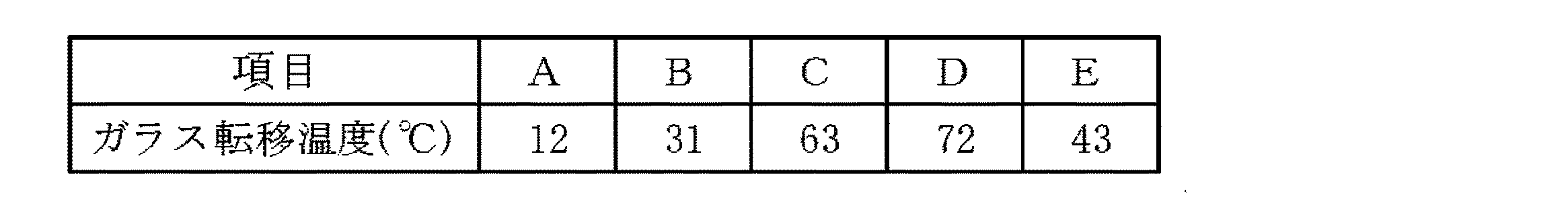
ジガルボン酸としてテレフタル酸、イソフタル酸又はアジピン酸を、ジオールとしてネオペンチルグリコールを、ジイソシアネートとして4,4’−ジフェニルメタンジイソシアネートを、表1に示す質量比となるようにそれぞれ用い、上記手順に従って各種ポリエステルウレタン樹脂A〜Eを得た。得られた各ポリエステルウレタン樹脂60gをメチルエチルケトン90gに溶解し、40質量%のポリエステルウレタン樹脂溶液を調製した。
(Synthesis of polyester urethane resins A to E)
Various polyester urethanes were used according to the above procedure, using terephthalic acid, isophthalic acid or adipic acid as digalbonic acid, neopentyl glycol as diol, and 4,4'-diphenylmethane diisocyanate as diisocyanate so as to have the mass ratio shown in Table 1, respectively. Resins A to E were obtained. 60 g of each obtained polyester urethane resin was melt | dissolved in 90 g of methyl ethyl ketone, and the 40 mass% polyester urethane resin solution was prepared.
(ポリエステルウレタン樹脂A〜Eのガラス転移温度の測定)
得られた各ポリエステルウレタン樹脂のガラス転移温度を、DSCを用いて以下の条件で測定した。各ポリエステルウレタン樹脂を0.01g秤量し、パーキンエルマー社製のDSC7(商品名)を用いて、窒素雰囲気下、温度範囲25〜200℃、昇温速度10℃/minで測定した。得られた吸熱曲線の変極点前後の直線を延長し、2本の延長線間の2分の1となる直線と吸熱曲線が交差する温度をガラス転移温度とした。測定結果を表2に示す。
(Measurement of glass transition temperature of polyester urethane resins A to E)
The glass transition temperature of each obtained polyester urethane resin was measured on condition of the following using DSC. 0.01 g of each polyester urethane resin was weighed and measured using DSC7 (trade name) manufactured by PerkinElmer Co., Ltd. under a nitrogen atmosphere at a temperature range of 25 to 200 ° C. and a heating rate of 10 ° C./min. The straight line before and after the inflection point of the obtained endothermic curve was extended, and the temperature at which the endothermic curve intersected with a half line between the two extended lines was defined as the glass transition temperature. The measurement results are shown in Table 2.
(ポリエステルウレタン樹脂A〜Eの重量平均分子量の測定)
得られた各ポリエステルウレタン樹脂の重量平均分子量を、ゲル浸透クロマトグラフィーを用いて測定した。カラムはGelpackGL−R440+GL−R450+GL−R400Mを用い、溶媒はテトラヒドロフランを用い、流量2.05ml/min、注入量200μl及び圧力519.4MPa(53kgf/cm2)の条件で測定した。検出器は、株式会社日立製作所製のL−3300RIを用いた。ポリスチレンを用いた検量線から各ポリエステルウレタン樹脂の重量平均分子量を算出した。その結果を表3に示す。
(Measurement of weight average molecular weight of polyester urethane resins A to E)
The weight average molecular weight of each obtained polyester urethane resin was measured using gel permeation chromatography. The column was GelpackGL-R440 + GL-R450 + GL-R400M, the solvent was tetrahydrofuran, and the flow rate was 2.05 ml / min, the injection amount was 200 μl, and the pressure was 519.4 MPa (53 kgf / cm 2 ). As the detector, L-3300RI manufactured by Hitachi, Ltd. was used. The weight average molecular weight of each polyester urethane resin was calculated from a calibration curve using polystyrene. The results are shown in Table 3.
(導電性粒子の作製)
ポリスチレン粒子の表面上に、厚さ0.2μmになるようにニッケルからなる層を設け、更にこのニッケルからなる層の表面上に、厚さ0.04μmになるように金からなる層を設けた。こうして平均粒径10μmの導電性粒子を作製した。
(Preparation of conductive particles)
A layer made of nickel was provided on the surface of the polystyrene particles so as to have a thickness of 0.2 μm, and a layer made of gold was provided on the surface of the layer made of nickel so as to have a thickness of 0.04 μm. . Thus, conductive particles having an average particle diameter of 10 μm were produced.
(実施例1〜5及び比較例1〜2)
熱可塑性樹脂として40質量%ポリエステルウレタン樹脂A〜E溶液、ラジカル重合性化合物としてイソシアヌル酸EO変性ジアクリレート(商品名:M−215、東亞合成株式会社製)、ウレタンアクリレート(商品名:AT−600、共栄社化学株式会社製)、2−(メタ)アクリロイロキシエチルホスフェート(商品名:ライトエステルP−2M、共栄社化学株式会社製)、及び、ラジカル重合開始剤として炭化水素希釈50質量%t−ヘキシルペルオキシ−2−エチルヘキサノエート(商品名:パーヘキシルO、1分間半減期温度:133℃、日本油脂株式会社製)を表4に示す配合量(単位:質量部)で配合し、更に上記の導電性粒子を全体の3体積%となるような量加えてこれを均一に分散させて、塗工用の分散液を得た。なお、表中の配合量は固形分の配合量を示す。次いで、得られた分散液を、片面を表面処理したPETフィルム(厚み80μm)に塗工装置を用いて塗布し、70℃で10分間熱風乾燥して、厚さ18μmのフィルム状の回路接続材料(接着剤組成物)を得た。
(Examples 1-5 and Comparative Examples 1-2)
40 mass% polyester urethane resins A to E solutions as thermoplastic resins, isocyanuric acid EO-modified diacrylate (trade name: M-215, manufactured by Toagosei Co., Ltd.), urethane acrylate (trade name: AT-600) as radical polymerizable compounds , Manufactured by Kyoeisha Chemical Co., Ltd.), 2- (meth) acryloyloxyethyl phosphate (trade name: Light Ester P-2M, manufactured by Kyoeisha Chemical Co., Ltd.), and
(比較例3)
ポリエステルウレタン樹脂Aの合成の際に用いたポリエステルポリオール(ガラス転移温度:−5℃)60gをメチルエチルケトン90gに溶解し40質量%の溶液にしてから、表1に示す配合量で配合した以外は実施例1〜5及び比較例1〜2と同様にして、フィルム状の回路接続材料(接着剤組成物)を得た。
(Comparative Example 3)
The procedure was carried out except that 60 g of the polyester polyol (glass transition temperature: −5 ° C.) used in the synthesis of the polyester urethane resin A was dissolved in 90 g of methyl ethyl ketone to form a 40 mass% solution, and then blended in the blending amounts shown in Table 1. In the same manner as in Examples 1 to 5 and Comparative Examples 1 and 2, a film-like circuit connecting material (adhesive composition) was obtained.
(接着強度及び接続抵抗の測定1)
実施例1〜5及び比較例1〜3で得られたフィルム状回路接続材料を用いて、ライン幅25μm、ピッチ50μm及び厚さ18μmの銅回路を500本有するフレキシブル回路板(FPC)と、厚さ0.2μmの酸化インジウム(ITO)の薄層を形成したガラス(厚さ1.1mm、表面抵抗20Ω/□)とを、熱圧着装置(加熱方式:コンスタントヒート型、東レエンジニアリング株式会社製)を用いて160℃の温度にて3MPaで10秒間の加熱加圧を行った。これにより、幅2mmにわたりFPC基板とITO基板とをフィルム状回路接続材料の硬化物により接続した接続体(回路接続構造体)を作製した。
(Measurement of adhesive strength and connection resistance 1)
Using the film-like circuit connecting materials obtained in Examples 1 to 5 and Comparative Examples 1 to 3, a flexible circuit board (FPC) having 500 copper circuits having a line width of 25 μm, a pitch of 50 μm, and a thickness of 18 μm, and a thickness A glass (thickness 1.1 mm, surface resistance 20Ω / □) on which a thin layer of indium oxide (ITO) having a thickness of 0.2 μm is formed, and a thermocompression bonding apparatus (heating method: constant heat type, manufactured by Toray Engineering Co., Ltd.) Was used for 10 seconds at 3 MPa at a temperature of 160 ° C. Thereby, the connection body (circuit connection structure) which connected the FPC board and the ITO board | substrate with the hardened | cured material of the film-form circuit connection material over width 2mm was produced.
この接続体の隣接回路間の抵抗値(接続抵抗)を、マルチメータで測定した。抵抗値は隣接回路間の抵抗37点の平均で示した。また、この接続体の接着強度を、JIS−Z0237に準じて90度剥離法で測定し、評価した。ここで、接着強度の測定装置は、東洋ボールドウィン株式会社製のテンシロンUTM−4(剥離速度50mm/min、25℃)を使用した。なお、接続抵抗及び接着強度は、接続直後、及び、85℃、85%RHの高温高湿槽中に168時間保持した後に測定した。それらの結果を表5に示す。
The resistance value (connection resistance) between adjacent circuits of this connection body was measured with a multimeter. The resistance value was shown as an average of 37 resistances between adjacent circuits. Moreover, the adhesive strength of this connection body was measured and evaluated by a 90-degree peeling method according to JIS-Z0237. Here, Tensilon UTM-4 (peeling
表5に示した結果から明らかなように、実施例1〜5で得られた接着剤組成物は、加熱温度160℃、時間10秒の低温かつ短時間の硬化条件において、接続直後及び85℃、85%RH高温高湿槽中に168時間保持した後で、良好な接続抵抗及び接着強度を示すことが確認された。これらに対し、ガラス転移温度が40℃以下のポリエステルウレタン樹脂を含まない比較例1〜2では、接続直後の接着強度は高いものの、85℃、85%RH高温高湿槽中で168時間後に接着強度が大幅に低下することが確認された。また、ガラス転移温度が40℃以下のポリエステルウレタン樹脂に代えて、ガラス転移温度が−5℃のポリエステルポリオールを用いた比較例3では接続直後の接着強度が低いことが確認された。 As is apparent from the results shown in Table 5, the adhesive compositions obtained in Examples 1 to 5 were heated immediately after connection and at 85 ° C. under a curing condition of a heating temperature of 160 ° C., a low temperature of 10 seconds and a short time. After holding in an 85% RH high-temperature and high-humidity tank for 168 hours, it was confirmed to show good connection resistance and adhesive strength. On the other hand, in Comparative Examples 1 and 2 that do not include a polyester urethane resin having a glass transition temperature of 40 ° C. or lower, the adhesive strength immediately after connection is high, but adhesion is performed after 168 hours in a 85 ° C., 85% RH high-temperature and high-humidity tank. It was confirmed that the strength was greatly reduced. Moreover, it replaced with the polyester urethane resin whose glass transition temperature is 40 degrees C or less, and it was confirmed that the adhesive strength immediately after a connection is low in the comparative example 3 using the polyester polyol whose glass transition temperature is -5 degreeC.
(実施例6〜7)
実施例1及び3で得られたフィルム状回路接続材料について、真空包装を施し、40℃で3日間放置した後、この放置後のフィルム状回路接続材料を用いて上記と同様にFPC基板とITO基板とを160℃、3MPa、10秒間の条件で加熱圧着した。以上のようにして作製した放置前後の接続体の接続抵抗、接着強度の測定結果を表6に示す。
(Examples 6 to 7)
The film-like circuit connecting material obtained in Examples 1 and 3 was vacuum packaged and left at 40 ° C. for 3 days, and then the film-like circuit connecting material after this standing was used in the same manner as described above for the FPC board and ITO. The substrate was thermocompression bonded at 160 ° C., 3 MPa, and 10 seconds. Table 6 shows the measurement results of the connection resistance and the adhesive strength of the connection body produced before and after being left as described above.
表6に示した結果から明らかなように、実施例6〜7で得られた接着剤組成物は、加熱温度160℃、時間10秒の低温かつ短時間の硬化条件において、40℃/3日の放置前後で良好な接続抵抗及び接着強度を示し、貯蔵安定性に優れることが確認された。 As is apparent from the results shown in Table 6, the adhesive compositions obtained in Examples 6 to 7 were 40 ° C./3 days under a curing condition of a heating temperature of 160 ° C., a low temperature of 10 seconds and a short time. It showed good connection resistance and adhesive strength before and after being left, and was excellent in storage stability.
1…フィルム状接着剤、2…半導体装置、5…接着剤成分、7…導電性粒子、10…回路接続部材、11…絶縁性物質、20…第一の回路部材、21…回路基板(第一の回路基板)、21a…主面、22…回路電極(第一の回路電極)、30…第二の回路部材、31…回路基板(第二の回路基板)、31a…主面、32…回路電極(第二の回路電極)、40…フィルム状回路接続材料、50…半導体素子、60…基板、61…回路パターン、70…封止材、80…半導体素子接続部材。
DESCRIPTION OF
Claims (6)
(b)ラジカル重合性化合物と、
(c)ラジカル重合開始剤と、
を含有する接着剤組成物であって、
前記(a)熱可塑性樹脂を2種類以上含有し、且つ、少なくとも1種の前記(a)熱可塑性樹脂のガラス転移温度が40℃以下であることを特徴とする接着剤組成物。 (A) a thermoplastic resin having a urethane bond and an ester bond in the same molecule;
(B) a radically polymerizable compound;
(C) a radical polymerization initiator;
An adhesive composition comprising:
An adhesive composition comprising two or more types of (a) thermoplastic resins, and at least one of the (a) thermoplastic resins having a glass transition temperature of 40 ° C. or lower.
前記一対の回路部材の間に設けられ、前記一対の回路部材が有する回路電極同士が電気的に接続されるように回路部材同士を接着する接続部材と、
を備え、
前記接続部材が、請求項1〜4のいずれか一項に記載の接着剤組成物の硬化物からなるものである、回路接続構造体。 A pair of circuit members disposed opposite to each other;
A connecting member that is provided between the pair of circuit members, and that bonds the circuit members such that the circuit electrodes of the pair of circuit members are electrically connected;
With
The circuit connection structure which the said connection member consists of the hardened | cured material of the adhesive composition as described in any one of Claims 1-4.
前記半導体素子を搭載する基板と、
前記半導体素子及び前記基板間に設けられ、前記半導体素子及び前記基板を電気的に接続するとともに接着する接続部材と、
を備え、
前記接続部材が、請求項1〜4のいずれか一項に記載の接着剤組成物の硬化物からなるものである、半導体装置。 A semiconductor element;
A substrate on which the semiconductor element is mounted;
A connecting member provided between the semiconductor element and the substrate, for electrically connecting and bonding the semiconductor element and the substrate;
With
The semiconductor device in which the said connection member consists of hardened | cured material of the adhesive composition as described in any one of Claims 1-4.
Priority Applications (2)
| Application Number | Priority Date | Filing Date | Title |
|---|---|---|---|
| JP2007229196A JP5023901B2 (en) | 2007-05-23 | 2007-09-04 | Adhesive composition, circuit connection structure, and semiconductor device |
| KR1020080047548A KR100973398B1 (en) | 2007-05-23 | 2008-05-22 | Adhesive Compositions, Circuit Connection Structures, and Semiconductor Devices |
Applications Claiming Priority (3)
| Application Number | Priority Date | Filing Date | Title |
|---|---|---|---|
| JP2007136701 | 2007-05-23 | ||
| JP2007136701 | 2007-05-23 | ||
| JP2007229196A JP5023901B2 (en) | 2007-05-23 | 2007-09-04 | Adhesive composition, circuit connection structure, and semiconductor device |
Publications (2)
| Publication Number | Publication Date |
|---|---|
| JP2009001765A true JP2009001765A (en) | 2009-01-08 |
| JP5023901B2 JP5023901B2 (en) | 2012-09-12 |
Family
ID=40318507
Family Applications (1)
| Application Number | Title | Priority Date | Filing Date |
|---|---|---|---|
| JP2007229196A Active JP5023901B2 (en) | 2007-05-23 | 2007-09-04 | Adhesive composition, circuit connection structure, and semiconductor device |
Country Status (1)
| Country | Link |
|---|---|
| JP (1) | JP5023901B2 (en) |
Cited By (7)
| Publication number | Priority date | Publication date | Assignee | Title |
|---|---|---|---|---|
| CN101955735A (en) * | 2009-07-17 | 2011-01-26 | 日立化成工业株式会社 | Adhesive composite and the syndeton body that uses the circuit block of said composition |
| JP2012067281A (en) * | 2010-08-24 | 2012-04-05 | Hitachi Chemical Co Ltd | Circuit connecting material, method for connecting circuit members using the same, circuit connection structure, and method for manufacturing circuit connection structure |
| KR20150111278A (en) * | 2014-03-25 | 2015-10-05 | 데쿠세리아루즈 가부시키가이샤 | Anisotropic conductive film, connection method, and joined structure |
| JP2016124933A (en) * | 2014-12-26 | 2016-07-11 | 株式会社タムラ製作所 | Anisotropic conductive paste and printed wiring board using the same |
| JP2016526586A (en) * | 2013-06-17 | 2016-09-05 | テーザ・ソシエタス・ヨーロピア | Reactive two-component adhesive film system |
| KR20190133021A (en) | 2017-03-29 | 2019-11-29 | 히타치가세이가부시끼가이샤 | Adhesive Compositions and Structures |
| US11898067B2 (en) | 2016-12-05 | 2024-02-13 | Tesa Se | Reactive 2-component adhesive system in film form having improved heat-and-humidity resistance |
Citations (7)
| Publication number | Priority date | Publication date | Assignee | Title |
|---|---|---|---|---|
| JPH0652715A (en) * | 1992-07-30 | 1994-02-25 | Fuji Kobunshi Kogyo Kk | Anisotropic conductive adhesive composite |
| JP2005530025A (en) * | 2002-06-19 | 2005-10-06 | スリーエム イノベイティブ プロパティズ カンパニー | Radiation curable, solventless and printable adhesive precursors |
| JP2005307210A (en) * | 1997-03-31 | 2005-11-04 | Hitachi Chem Co Ltd | Circuit connection material, circuit terminal connection structure and connection method |
| JP2005322938A (en) * | 1999-08-25 | 2005-11-17 | Hitachi Chem Co Ltd | Wiring connecting material and wiring board manufacturing method using the same |
| JP2006052258A (en) * | 2004-08-10 | 2006-02-23 | Unitika Ltd | Active energy ray-curing resin composition |
| JP2006269887A (en) * | 2005-03-25 | 2006-10-05 | Sumitomo Bakelite Co Ltd | Adhesive film for semiconductor and semiconductor device using the same |
| JP2006318990A (en) * | 2005-05-10 | 2006-11-24 | Hitachi Chem Co Ltd | Circuit connecting material, connection structure of circuit member and method of connecting the same |
-
2007
- 2007-09-04 JP JP2007229196A patent/JP5023901B2/en active Active
Patent Citations (7)
| Publication number | Priority date | Publication date | Assignee | Title |
|---|---|---|---|---|
| JPH0652715A (en) * | 1992-07-30 | 1994-02-25 | Fuji Kobunshi Kogyo Kk | Anisotropic conductive adhesive composite |
| JP2005307210A (en) * | 1997-03-31 | 2005-11-04 | Hitachi Chem Co Ltd | Circuit connection material, circuit terminal connection structure and connection method |
| JP2005322938A (en) * | 1999-08-25 | 2005-11-17 | Hitachi Chem Co Ltd | Wiring connecting material and wiring board manufacturing method using the same |
| JP2005530025A (en) * | 2002-06-19 | 2005-10-06 | スリーエム イノベイティブ プロパティズ カンパニー | Radiation curable, solventless and printable adhesive precursors |
| JP2006052258A (en) * | 2004-08-10 | 2006-02-23 | Unitika Ltd | Active energy ray-curing resin composition |
| JP2006269887A (en) * | 2005-03-25 | 2006-10-05 | Sumitomo Bakelite Co Ltd | Adhesive film for semiconductor and semiconductor device using the same |
| JP2006318990A (en) * | 2005-05-10 | 2006-11-24 | Hitachi Chem Co Ltd | Circuit connecting material, connection structure of circuit member and method of connecting the same |
Cited By (12)
| Publication number | Priority date | Publication date | Assignee | Title |
|---|---|---|---|---|
| CN101955735A (en) * | 2009-07-17 | 2011-01-26 | 日立化成工业株式会社 | Adhesive composite and the syndeton body that uses the circuit block of said composition |
| JP2012067281A (en) * | 2010-08-24 | 2012-04-05 | Hitachi Chemical Co Ltd | Circuit connecting material, method for connecting circuit members using the same, circuit connection structure, and method for manufacturing circuit connection structure |
| JP2016526586A (en) * | 2013-06-17 | 2016-09-05 | テーザ・ソシエタス・ヨーロピア | Reactive two-component adhesive film system |
| US10400140B2 (en) | 2013-06-17 | 2019-09-03 | Tesa Se | Reactive 2-component adhesive film system |
| US10711163B2 (en) | 2013-06-17 | 2020-07-14 | Tesa Se | Reactive 2-component adhesive film system |
| KR20150111278A (en) * | 2014-03-25 | 2015-10-05 | 데쿠세리아루즈 가부시키가이샤 | Anisotropic conductive film, connection method, and joined structure |
| JP2015185399A (en) * | 2014-03-25 | 2015-10-22 | デクセリアルズ株式会社 | Anisotropic conductive film, connection method and joined body |
| TWI645420B (en) * | 2014-03-25 | 2018-12-21 | 日商迪睿合股份有限公司 | Anisotropic conductive film, connection method, and joined structure |
| KR102395930B1 (en) * | 2014-03-25 | 2022-05-09 | 데쿠세리아루즈 가부시키가이샤 | Anisotropic conductive film, connection method, and joined structure |
| JP2016124933A (en) * | 2014-12-26 | 2016-07-11 | 株式会社タムラ製作所 | Anisotropic conductive paste and printed wiring board using the same |
| US11898067B2 (en) | 2016-12-05 | 2024-02-13 | Tesa Se | Reactive 2-component adhesive system in film form having improved heat-and-humidity resistance |
| KR20190133021A (en) | 2017-03-29 | 2019-11-29 | 히타치가세이가부시끼가이샤 | Adhesive Compositions and Structures |
Also Published As
| Publication number | Publication date |
|---|---|
| JP5023901B2 (en) | 2012-09-12 |
Similar Documents
| Publication | Publication Date | Title |
|---|---|---|
| JP5012903B2 (en) | Circuit connection adhesive composition, circuit connection film adhesive and circuit member connection structure | |
| JP4998468B2 (en) | Adhesive composition and circuit member connection structure | |
| CN102277124B (en) | Adhesive composition, circuit connecting material, connection structure of circuit member, and semiconductor device | |
| JP5456475B2 (en) | Adhesive and connection structure using the same | |
| JP4760070B2 (en) | Adhesive, adhesive for circuit connection, connector and semiconductor device | |
| JP6045918B2 (en) | Circuit connection material, circuit connection member connection structure, and semiconductor device | |
| JP5023901B2 (en) | Adhesive composition, circuit connection structure, and semiconductor device | |
| JP5292838B2 (en) | Adhesive and circuit member connection structure | |
| JP5293779B2 (en) | Adhesive composition, circuit connection structure, semiconductor device and solar cell module | |
| JP2011037953A (en) | Adhesive agent composition, circuit-connecting structure and semiconductor device | |
| JP5298977B2 (en) | Adhesive composition, adhesive for circuit connection, connector and semiconductor device | |
| JP5338051B2 (en) | Adhesive composition, circuit connection structure, and semiconductor device | |
| JP5070748B2 (en) | Adhesive composition, circuit connection material, connection body and semiconductor device | |
| JP2012204059A (en) | Circuit connection material and circuit connection structure using the same | |
| JP5034494B2 (en) | Adhesive composition, adhesive for circuit connection, connector and semiconductor device | |
| KR100973398B1 (en) | Adhesive Compositions, Circuit Connection Structures, and Semiconductor Devices | |
| TWI570208B (en) | Circuit connecting material and connection body | |
| JP2011157557A (en) | Adhesive, adhesive for circuit connection, connected body and semiconductor device |
Legal Events
| Date | Code | Title | Description |
|---|---|---|---|
| A621 | Written request for application examination |
Free format text: JAPANESE INTERMEDIATE CODE: A621 Effective date: 20091119 |
|
| A131 | Notification of reasons for refusal |
Free format text: JAPANESE INTERMEDIATE CODE: A131 Effective date: 20120124 |
|
| A521 | Request for written amendment filed |
Free format text: JAPANESE INTERMEDIATE CODE: A523 Effective date: 20120326 |
|
| TRDD | Decision of grant or rejection written | ||
| A01 | Written decision to grant a patent or to grant a registration (utility model) |
Free format text: JAPANESE INTERMEDIATE CODE: A01 Effective date: 20120522 |
|
| A01 | Written decision to grant a patent or to grant a registration (utility model) |
Free format text: JAPANESE INTERMEDIATE CODE: A01 |
|
| A61 | First payment of annual fees (during grant procedure) |
Free format text: JAPANESE INTERMEDIATE CODE: A61 Effective date: 20120604 |
|
| FPAY | Renewal fee payment (event date is renewal date of database) |
Free format text: PAYMENT UNTIL: 20150629 Year of fee payment: 3 |
|
| R151 | Written notification of patent or utility model registration |
Ref document number: 5023901 Country of ref document: JP Free format text: JAPANESE INTERMEDIATE CODE: R151 |
|
| S531 | Written request for registration of change of domicile |
Free format text: JAPANESE INTERMEDIATE CODE: R313531 |
|
| S533 | Written request for registration of change of name |
Free format text: JAPANESE INTERMEDIATE CODE: R313533 |
|
| FPAY | Renewal fee payment (event date is renewal date of database) |
Free format text: PAYMENT UNTIL: 20150629 Year of fee payment: 3 |
|
| R350 | Written notification of registration of transfer |
Free format text: JAPANESE INTERMEDIATE CODE: R350 |
|
| S531 | Written request for registration of change of domicile |
Free format text: JAPANESE INTERMEDIATE CODE: R313531 |
|
| S533 | Written request for registration of change of name |
Free format text: JAPANESE INTERMEDIATE CODE: R313533 |
|
| R350 | Written notification of registration of transfer |
Free format text: JAPANESE INTERMEDIATE CODE: R350 |
|
| S531 | Written request for registration of change of domicile |
Free format text: JAPANESE INTERMEDIATE CODE: R313531 |
|
| R350 | Written notification of registration of transfer |
Free format text: JAPANESE INTERMEDIATE CODE: R350 |