JP2008538612A - Configuration, system, and method capable of providing spectral domain polarization sensitive optical coherence tomography - Google Patents
Configuration, system, and method capable of providing spectral domain polarization sensitive optical coherence tomography Download PDFInfo
- Publication number
- JP2008538612A JP2008538612A JP2008507983A JP2008507983A JP2008538612A JP 2008538612 A JP2008538612 A JP 2008538612A JP 2008507983 A JP2008507983 A JP 2008507983A JP 2008507983 A JP2008507983 A JP 2008507983A JP 2008538612 A JP2008538612 A JP 2008538612A
- Authority
- JP
- Japan
- Prior art keywords
- configuration
- electromagnetic radiation
- polarization
- radiation
- elements
- Prior art date
- Legal status (The legal status is an assumption and is not a legal conclusion. Google has not performed a legal analysis and makes no representation as to the accuracy of the status listed.)
- Withdrawn
Links
- 230000010287 polarization Effects 0.000 title claims abstract description 90
- 238000000034 method Methods 0.000 title claims abstract description 59
- 238000012014 optical coherence tomography Methods 0.000 title description 56
- 230000003595 spectral effect Effects 0.000 title description 23
- 230000005670 electromagnetic radiation Effects 0.000 claims abstract description 45
- 230000005855 radiation Effects 0.000 claims abstract description 23
- 230000003287 optical effect Effects 0.000 claims description 33
- 238000001514 detection method Methods 0.000 claims description 24
- 208000010412 Glaucoma Diseases 0.000 description 43
- 238000005259 measurement Methods 0.000 description 43
- 241000282414 Homo sapiens Species 0.000 description 26
- 210000004126 nerve fiber Anatomy 0.000 description 23
- 238000001228 spectrum Methods 0.000 description 22
- 230000002207 retinal effect Effects 0.000 description 19
- 238000001727 in vivo Methods 0.000 description 17
- 239000000835 fiber Substances 0.000 description 16
- 229940125730 polarisation modulator Drugs 0.000 description 13
- 230000002123 temporal effect Effects 0.000 description 12
- 238000000506 liquid--solid chromatography Methods 0.000 description 11
- 230000005540 biological transmission Effects 0.000 description 10
- 238000004458 analytical method Methods 0.000 description 9
- 230000008901 benefit Effects 0.000 description 9
- 238000003384 imaging method Methods 0.000 description 9
- 206010047555 Visual field defect Diseases 0.000 description 7
- 230000000007 visual effect Effects 0.000 description 7
- 238000009825 accumulation Methods 0.000 description 6
- 238000010586 diagram Methods 0.000 description 6
- 238000012935 Averaging Methods 0.000 description 5
- 239000006185 dispersion Substances 0.000 description 5
- 210000001525 retina Anatomy 0.000 description 5
- 230000035945 sensitivity Effects 0.000 description 5
- 230000001360 synchronised effect Effects 0.000 description 5
- 230000004075 alteration Effects 0.000 description 4
- 230000007423 decrease Effects 0.000 description 4
- 238000002474 experimental method Methods 0.000 description 4
- 238000013507 mapping Methods 0.000 description 4
- 210000003733 optic disk Anatomy 0.000 description 4
- 238000006073 displacement reaction Methods 0.000 description 3
- 230000000694 effects Effects 0.000 description 3
- 210000005036 nerve Anatomy 0.000 description 3
- 102000008186 Collagen Human genes 0.000 description 2
- 108010035532 Collagen Proteins 0.000 description 2
- 101150072399 LSC1 gene Proteins 0.000 description 2
- 206010028980 Neoplasm Diseases 0.000 description 2
- 230000009286 beneficial effect Effects 0.000 description 2
- 230000008033 biological extinction Effects 0.000 description 2
- 229920001436 collagen Polymers 0.000 description 2
- 238000011109 contamination Methods 0.000 description 2
- 238000005516 engineering process Methods 0.000 description 2
- 230000004438 eyesight Effects 0.000 description 2
- 238000009499 grossing Methods 0.000 description 2
- 230000006872 improvement Effects 0.000 description 2
- 230000033001 locomotion Effects 0.000 description 2
- 230000002911 mydriatic effect Effects 0.000 description 2
- 210000001328 optic nerve Anatomy 0.000 description 2
- 230000008569 process Effects 0.000 description 2
- 238000012545 processing Methods 0.000 description 2
- 238000002310 reflectometry Methods 0.000 description 2
- 230000011218 segmentation Effects 0.000 description 2
- 238000000926 separation method Methods 0.000 description 2
- 238000012360 testing method Methods 0.000 description 2
- 230000001131 transforming effect Effects 0.000 description 2
- 238000002604 ultrasonography Methods 0.000 description 2
- 208000024172 Cardiovascular disease Diseases 0.000 description 1
- 208000002177 Cataract Diseases 0.000 description 1
- 208000003098 Ganglion Cysts Diseases 0.000 description 1
- 208000006550 Mydriasis Diseases 0.000 description 1
- 206010030348 Open-Angle Glaucoma Diseases 0.000 description 1
- 208000007479 Orofaciodigital syndrome type 1 Diseases 0.000 description 1
- 241000283973 Oryctolagus cuniculus Species 0.000 description 1
- 101100367016 Saccharomyces cerevisiae (strain ATCC 204508 / S288c) LSC2 gene Proteins 0.000 description 1
- 208000005400 Synovial Cyst Diseases 0.000 description 1
- BGDKAVGWHJFAGW-UHFFFAOYSA-N Tropicamide Chemical compound C=1C=CC=CC=1C(CO)C(=O)N(CC)CC1=CC=NC=C1 BGDKAVGWHJFAGW-UHFFFAOYSA-N 0.000 description 1
- 208000003443 Unconsciousness Diseases 0.000 description 1
- 229960000074 biopharmaceutical Drugs 0.000 description 1
- 230000004397 blinking Effects 0.000 description 1
- 210000004204 blood vessel Anatomy 0.000 description 1
- 201000011510 cancer Diseases 0.000 description 1
- 210000004027 cell Anatomy 0.000 description 1
- 230000008859 change Effects 0.000 description 1
- 210000004087 cornea Anatomy 0.000 description 1
- 210000004351 coronary vessel Anatomy 0.000 description 1
- 230000001186 cumulative effect Effects 0.000 description 1
- 238000007405 data analysis Methods 0.000 description 1
- 238000013075 data extraction Methods 0.000 description 1
- 230000007123 defense Effects 0.000 description 1
- 230000007812 deficiency Effects 0.000 description 1
- 230000003111 delayed effect Effects 0.000 description 1
- 238000013461 design Methods 0.000 description 1
- 238000003745 diagnosis Methods 0.000 description 1
- 238000013399 early diagnosis Methods 0.000 description 1
- 238000000572 ellipsometry Methods 0.000 description 1
- 210000003238 esophagus Anatomy 0.000 description 1
- 230000004424 eye movement Effects 0.000 description 1
- 239000011521 glass Substances 0.000 description 1
- 230000036541 health Effects 0.000 description 1
- 238000010191 image analysis Methods 0.000 description 1
- 238000000338 in vitro Methods 0.000 description 1
- 238000012623 in vivo measurement Methods 0.000 description 1
- 238000011835 investigation Methods 0.000 description 1
- 239000000463 material Substances 0.000 description 1
- 239000011159 matrix material Substances 0.000 description 1
- 238000012986 modification Methods 0.000 description 1
- 230000004048 modification Effects 0.000 description 1
- 210000004498 neuroglial cell Anatomy 0.000 description 1
- 230000007935 neutral effect Effects 0.000 description 1
- 210000002445 nipple Anatomy 0.000 description 1
- 238000005457 optimization Methods 0.000 description 1
- 201000003455 orofaciodigital syndrome I Diseases 0.000 description 1
- 229960003733 phenylephrine hydrochloride Drugs 0.000 description 1
- OCYSGIYOVXAGKQ-FVGYRXGTSA-N phenylephrine hydrochloride Chemical compound [H+].[Cl-].CNC[C@H](O)C1=CC=CC(O)=C1 OCYSGIYOVXAGKQ-FVGYRXGTSA-N 0.000 description 1
- 238000012805 post-processing Methods 0.000 description 1
- 210000001747 pupil Anatomy 0.000 description 1
- 238000003908 quality control method Methods 0.000 description 1
- 230000008929 regeneration Effects 0.000 description 1
- 238000011069 regeneration method Methods 0.000 description 1
- 230000003252 repetitive effect Effects 0.000 description 1
- 238000011160 research Methods 0.000 description 1
- 238000012827 research and development Methods 0.000 description 1
- 238000001356 surgical procedure Methods 0.000 description 1
- 210000002435 tendon Anatomy 0.000 description 1
- 238000003325 tomography Methods 0.000 description 1
- 238000013519 translation Methods 0.000 description 1
- 230000001960 triggered effect Effects 0.000 description 1
- 229960004791 tropicamide Drugs 0.000 description 1
- 230000004304 visual acuity Effects 0.000 description 1
- XLYOFNOQVPJJNP-UHFFFAOYSA-N water Substances O XLYOFNOQVPJJNP-UHFFFAOYSA-N 0.000 description 1
Images


Classifications
-
- G—PHYSICS
- G01—MEASURING; TESTING
- G01N—INVESTIGATING OR ANALYSING MATERIALS BY DETERMINING THEIR CHEMICAL OR PHYSICAL PROPERTIES
- G01N21/00—Investigating or analysing materials by the use of optical means, i.e. using sub-millimetre waves, infrared, visible or ultraviolet light
- G01N21/17—Systems in which incident light is modified in accordance with the properties of the material investigated
- G01N21/47—Scattering, i.e. diffuse reflection
-
- A—HUMAN NECESSITIES
- A61—MEDICAL OR VETERINARY SCIENCE; HYGIENE
- A61B—DIAGNOSIS; SURGERY; IDENTIFICATION
- A61B3/00—Apparatus for testing the eyes; Instruments for examining the eyes
- A61B3/10—Objective types, i.e. instruments for examining the eyes independent of the patients' perceptions or reactions
- A61B3/1005—Objective types, i.e. instruments for examining the eyes independent of the patients' perceptions or reactions for measuring distances inside the eye, e.g. thickness of the cornea
-
- A—HUMAN NECESSITIES
- A61—MEDICAL OR VETERINARY SCIENCE; HYGIENE
- A61B—DIAGNOSIS; SURGERY; IDENTIFICATION
- A61B3/00—Apparatus for testing the eyes; Instruments for examining the eyes
- A61B3/10—Objective types, i.e. instruments for examining the eyes independent of the patients' perceptions or reactions
- A61B3/102—Objective types, i.e. instruments for examining the eyes independent of the patients' perceptions or reactions for optical coherence tomography [OCT]
-
- G—PHYSICS
- G01—MEASURING; TESTING
- G01B—MEASURING LENGTH, THICKNESS OR SIMILAR LINEAR DIMENSIONS; MEASURING ANGLES; MEASURING AREAS; MEASURING IRREGULARITIES OF SURFACES OR CONTOURS
- G01B9/00—Measuring instruments characterised by the use of optical techniques
- G01B9/02—Interferometers
-
- G—PHYSICS
- G01—MEASURING; TESTING
- G01N—INVESTIGATING OR ANALYSING MATERIALS BY DETERMINING THEIR CHEMICAL OR PHYSICAL PROPERTIES
- G01N21/00—Investigating or analysing materials by the use of optical means, i.e. using sub-millimetre waves, infrared, visible or ultraviolet light
- G01N21/17—Systems in which incident light is modified in accordance with the properties of the material investigated
- G01N21/21—Polarisation-affecting properties
-
- G—PHYSICS
- G01—MEASURING; TESTING
- G01N—INVESTIGATING OR ANALYSING MATERIALS BY DETERMINING THEIR CHEMICAL OR PHYSICAL PROPERTIES
- G01N21/00—Investigating or analysing materials by the use of optical means, i.e. using sub-millimetre waves, infrared, visible or ultraviolet light
- G01N21/17—Systems in which incident light is modified in accordance with the properties of the material investigated
- G01N21/47—Scattering, i.e. diffuse reflection
- G01N21/4795—Scattering, i.e. diffuse reflection spatially resolved investigating of object in scattering medium
-
- A—HUMAN NECESSITIES
- A61—MEDICAL OR VETERINARY SCIENCE; HYGIENE
- A61B—DIAGNOSIS; SURGERY; IDENTIFICATION
- A61B3/00—Apparatus for testing the eyes; Instruments for examining the eyes
- A61B3/10—Objective types, i.e. instruments for examining the eyes independent of the patients' perceptions or reactions
- A61B3/117—Objective types, i.e. instruments for examining the eyes independent of the patients' perceptions or reactions for examining the anterior chamber or the anterior chamber angle, e.g. gonioscopes
- A61B3/1173—Objective types, i.e. instruments for examining the eyes independent of the patients' perceptions or reactions for examining the anterior chamber or the anterior chamber angle, e.g. gonioscopes for examining the eye lens
- A61B3/1176—Objective types, i.e. instruments for examining the eyes independent of the patients' perceptions or reactions for examining the anterior chamber or the anterior chamber angle, e.g. gonioscopes for examining the eye lens for determining lens opacity, e.g. cataract
Landscapes
- Health & Medical Sciences (AREA)
- Life Sciences & Earth Sciences (AREA)
- Physics & Mathematics (AREA)
- General Health & Medical Sciences (AREA)
- General Physics & Mathematics (AREA)
- Chemical & Material Sciences (AREA)
- Analytical Chemistry (AREA)
- Biochemistry (AREA)
- Immunology (AREA)
- Pathology (AREA)
- Engineering & Computer Science (AREA)
- Surgery (AREA)
- Biophysics (AREA)
- Ophthalmology & Optometry (AREA)
- Veterinary Medicine (AREA)
- Biomedical Technology (AREA)
- Heart & Thoracic Surgery (AREA)
- Medical Informatics (AREA)
- Molecular Biology (AREA)
- Public Health (AREA)
- Animal Behavior & Ethology (AREA)
- Radiology & Medical Imaging (AREA)
- Nuclear Medicine, Radiotherapy & Molecular Imaging (AREA)
- Optics & Photonics (AREA)
- Investigating Or Analysing Materials By Optical Means (AREA)
- Length Measuring Devices By Optical Means (AREA)
- Eye Examination Apparatus (AREA)
- Mechanical Optical Scanning Systems (AREA)
Abstract
電磁放射を分離し、電磁放射を使用してサンプルの情報を入手するシステム、構成、及び方法が提供されている。具体的には、電磁放射の少なくとも1つの偏光及び少なくとも1つの波長に従って電磁放射を少なくとも1つの第1部分及び少なくとも1つの第2部分に分離可能である。第1及び第2の分離された部分を同時に検出可能である。更には、第1放射をサンプルから入手可能であり、且つ、第2放射を基準から入手可能であり、第1及び第2放射を合成して更なる放射を形成可能であり、この場合に、第1及び第2放射は、電磁放射と関連付けられている。情報は、以前に分離された更なる放射の第1及び第2部分の関数として提供され、これを分析することにより、サンプルを特徴付けている複屈折情報を抽出可能である。
【選択図】図1Systems, configurations, and methods are provided for separating electromagnetic radiation and using electromagnetic radiation to obtain sample information. In particular, the electromagnetic radiation can be separated into at least one first part and at least one second part according to at least one polarization and at least one wavelength of the electromagnetic radiation. The first and second separated parts can be detected simultaneously. Furthermore, the first radiation can be obtained from the sample, and the second radiation can be obtained from the reference, and the first and second radiation can be combined to form further radiation, in which case The first and second radiation are associated with electromagnetic radiation. Information is provided as a function of the first and second portions of further radiation previously separated, and by analyzing this, birefringence information characterizing the sample can be extracted.
[Selection] Figure 1
Description
本発明は、光学画像生成に関するものであり、更に詳しくは、スペクトルドメイン偏光検出型光干渉断層法を提供する能力を有する構成、システム、及び方法に関するものである。 The present invention relates to optical image generation and, more particularly, to an arrangement, system, and method having the ability to provide spectral domain polarization detection optical coherence tomography.
(関連出願に対する相互参照)
本出願は、2005年4月22日付けで出願された米国特許出願第60/674,008号に基づくものであって、これに対する優先権の利益を主張するものであり、この開示内容は、本引用により、そのすべてが本明細書に包含される。
(連邦政府による資金提供をうけた研究開発の記載)
本発明は、国立衛生研究所によって付与された契約第RO1EY014975号及び第RO1RR019768号、並びに、国防省によって付与された契約第F49620−021−1−0014号の下に米国政府の支援によって行われたものである。従って、米国政府は、本発明において特定の権利を保有している。
偏光感受型光コヒーレンストモグラフィ(Polarization−Sensitive Optial Coherence Tomography:PS−OCT)システムの取得速度は、時間ドメイン技術を置換することによって大幅に向上させることが可能であり、この例は、J. F. de Boer他による「Two−dimensional birefringence imaging in biological tissue by polarization−sensitive optical coherence tomography」(Optics Letters、1997年、第22(12)巻、934〜936頁)及びB. H. Park他による「Real−time multi−functional optical coherence tomography」(Optics Express、2003年、第11(7)巻、782〜793頁)に記述されている。
(Cross-reference to related applications)
This application is based on US Patent Application No. 60 / 674,008, filed on April 22, 2005, and claims the benefit of priority thereto, the disclosure of which is All of which are hereby incorporated by reference.
(Description of research and development funded by the federal government)
This invention was made with US Government support under Contracts RO1EY014975 and RO1RR019766 granted by the National Institutes of Health, and Contract F49620-021-1-0014 awarded by the Department of Defense. Is. Accordingly, the US government has certain rights in this invention.
The acquisition speed of a polarization-sensitive optical coherence tomography (PS-OCT) system can be significantly improved by replacing the time-domain technique. F. de Boer et al., “Two-dimensional birefringence imaging in biological tissue-polarization-sensitive optical coherence tomography” (Vol. 9, Vol. 9, Vol. 9, Vol. H. Park et al., "Real-time multi-functional optical coherence tomography" (Optics Express, 2003, 11 (7), 782-793).
1つの模範的なスペクトルドメイン(SD)のファイバに基づいたシステムが、N. Nassif他による「In vivo human retinal imaging by ultrahigh−speed spectral domain optical coherence tomography」(Optics Letters、2004年、第29(5)巻、480〜482頁)及びN. A. Nassif他による「In vivo high−resolution video−rate spectral−domain optical coherence tomography of the human retina and optic nerve」(Optics Express、2004年、第12(3)巻、367〜376頁)に記述されている。これらの文献は、例えば、高速のデータ取得や改善された信号対雑音比などの時間ドメイン分析に対するスペクトルドメイン分析の利点について記述している。例えば、Michelson干渉計の出力における干渉の光学スペクトルをフーリエ変換することにより、構造情報(即ち、深さプロファイル)を取得可能である。 One exemplary spectral domain (SD) fiber based system is described in N.C. Nassif et al., “In vivo human imaging by ultrahigh-speed spectral domain optical coherence tomography” (Optics Letters, 2004, Vol. 29-48). A. Nasif et al., “In vivo high-resolution video-rate spectral-domain optical coherence of the human remanufacturing of the human retina and optical nr.”, Op.3, Op. . These documents describe the advantages of spectral domain analysis over time domain analysis such as, for example, fast data acquisition and improved signal-to-noise ratio. For example, structural information (ie, depth profile) can be obtained by Fourier transforming the optical spectrum of interference at the output of the Michelson interferometer.
又、J. F. de Boer他による「Two−dimensional birefringence imaging in biological tissue by polarization−sensitive optical coherence tomography」(Optics Letters、1997年、第22(12)巻、934〜936頁)には、模範的な偏光感受型時間ドメインシステム、並びに、ファイバに基づいたシステムについて記述されている。 In addition, J.H. F. de Boer et al., “Two-dimensional birefringence imaging in biologic tissue-by-polarization-sensitive optical coherence tomography” (Volume 9 to 19; Optics 97, Letters 97, Letters 97, Letters 97, Letters 97 Domain systems as well as fiber based systems are described.
例えば、既知の時間ドメインOCTシステムによって取得された健康なボランティアからの画像品質及び偏光検出型の結果をB. Cense他による「Thickness and birefringence of retinal nerve fiber layer of healthy and glaucomatous subject measured with polarization sensitive optical coherence tomography」(Ophthalmic Technologies XIV、2004年、Proceedings of SPIE、第5314巻、179〜187頁)に記述されている緑内障患者のものと比較可能である。 For example, image quality and polarization detection-type results from healthy volunteers acquired by known time domain OCT systems are described in B.C. Cense et al., "Thickness and birefringence of retinal nerve fiber layer of healthy and glaucomatous subject measured with polarization sensitive optical coherence tomography" (Ophthalmic Technologies XIV, 2004 years, Proceedings of SPIE, the 5314, pp. 179-187) is described in the It is comparable to that of glaucoma patients.
緑内障患者から得られた画像内における相対的に低い信号対雑音比が、恐らくは、信頼性の低い結果の原因であろうと確認された。更には、健康な被検者から得られた分析結果である網膜神経線維層(Retinal Nerve Fiber Layer:RNFL)の厚さ及びDPPR/UD(Double−Pass Phase Retardation per Unit Depth)データから、この文献に記述されているように、信頼性の高い複屈折計測のためには、75μmを上回るRNFLの厚さを使用する必要があることが確認された。この文献に示されているように、計測された大部分の緑内障の神経線維層の厚さは、この限度未満であるため、完全な緑内障データセットを取得することができなかった。更には、この文献に記述されている時間ドメインシステムにおける1スキャン当たりには6秒、そして、完全なデータセットにおいては72秒という長い取得時間は、無意識の眼の動き及び頻繁な瞬きによって引き起こされるデータ損失に起因した信頼性の低いデータを結果的にもたらしている。 It has been determined that the relatively low signal-to-noise ratio in images obtained from glaucoma patients is probably the cause of unreliable results. Furthermore, from the thickness of the retinal nerve fiber layer (RNFL) and the DPPR / UD (Double-Pass Phase Repetition per Depth) data, which are analysis results obtained from healthy subjects, It has been confirmed that for reliable birefringence measurements, it is necessary to use an RNFL thickness greater than 75 μm. As shown in this document, the measured glaucoma nerve fiber layer thickness was below this limit, so a complete glaucoma dataset could not be obtained. Furthermore, the long acquisition time of 6 seconds per scan in the time domain system described in this document and 72 seconds in the complete data set is caused by unconscious eye movements and frequent blinks. This results in unreliable data due to data loss.
Y. Yasuno他による「Birefringence imaging of human skin by polarization−sensitive spectral interferometric optical coherence tomography」(Optics Letters、2002年、第27(20)巻、1803〜1805頁)及びY. Yasuno他による「Polarization−sensitive complex Fourier domain optical coherence tomography for Jones matrix imaging of biological samples」(Applied Physics Letters、2004年、第85(15)巻、3023〜3025頁)には、分光計に基づいたフーリエドメインシステムを使用した生体外におけるヒトの皮膚並びに生体外におけるブタの食道の複屈折計測について記述されている。これらの文献においては、Aラインの計測レートについては記述されていない。計測については、J. Zhang他による「Full range polarization−sensitive Fourier domain optical coherence tomography」(Optics Express、2004年、第12(24)巻、6033〜6039頁)において提供されている偏光感受型OFDI(Optical Frequency−domain Imaging)システムを使用し、生体外におけるウサギの腱について記述されている。このようなシステムのAラインレートは、250Hzであり、これは、従来の時間ドメインPS−OCTシステムと比較した場合に、改善ではなかったと思われる。時間ドメインOCTに対するスペクトルドメインOCTの特定の利点(これらは、相対的に高い感度及び相対的に高い取得レートである)は、前述の文献によって実証されてはいない。これらの改善は、生体内における計測にとって好ましいものである。以下に記述されているのは、生体内における緑内障患者の網膜神経線維層の厚さ及びDPPR/UDを計測することによって得ることができる特定の利点である。 Y. Yasuno et al., “Birefrenceence imaging of human skin by polarization-sensitive spectral interferometric optical coherence tomography” (Vol. 3 to Y, 180, Y. Yasuno et al., "Polarization-sensitive complex Fourier domain optical optical coherence tomography for Jones matrix imaging of biologics, p. 30, p. It describes the birefringence measurement of human skin ex vivo and porcine esophagus using the domain system. In these documents, the measurement rate of the A line is not described. For the measurement, see J.H. Z ang et al., “Full Range Polarization-sensitive Fourier domain optical coherence tomography” (Optic Express, 2004, Vol. 12 (24), 6033-6039). The system is used to describe rabbit tendons in vitro. The A-line rate of such a system is 250 Hz, which appears to have not been an improvement when compared to conventional time domain PS-OCT systems. The particular advantages of spectral domain OCT over time domain OCT (these are relatively high sensitivity and relatively high acquisition rate) have not been demonstrated by the aforementioned literature. These improvements are preferable for in vivo measurements. Described below are certain advantages that can be obtained by measuring retinal nerve fiber layer thickness and DPPR / UD in glaucoma patients in vivo.
本発明の目的の1つは、従来技術によるシステムの(前述のものを含む)欠陥及び欠点を克服すると共に、スペクトルドメイン偏光感受型光コヒーレンストモグラフィを提供することの可能な構成、システム、及び方法の具体例を提供することにある。これは、(例えば、PS−SD−OCT構成、システム、及び方法などの)PS−OCTにおけるスペクトルドメイン(Spectral−Domain:SD)分析、構成、システム、及び方法を実現することにより可能となる。 One of the objects of the present invention is an arrangement, system, and system that can overcome the deficiencies and disadvantages (including those described above) of prior art systems and provide spectral domain polarization sensitive optical coherence tomography, and It is to provide a specific example of the method. This is made possible by implementing spectral-domain (SD) analysis, configurations, systems, and methods in PS-OCT (eg, PS-SD-OCT configurations, systems, and methods).
例えば、偏光の2つの連続生成入力状態における2つの直交偏光チャネルにおいてOCTシステムからの干渉分光信号を同時に分析することにより、調査対象の組織(サンプル又はターゲットなど)の偏光検出特性を取得可能である。本発明の一具体例によれば、例示的なPS−SD−OCT構成、システム、及び方法において高速分光計の様々な構成を使用可能である。 For example, the polarization detection characteristics of the tissue under investigation (such as a sample or target) can be obtained by simultaneously analyzing the interferometric spectral signals from the OCT system in two orthogonal polarization channels in two consecutively generated input states of polarization. . In accordance with one embodiment of the present invention, various configurations of high speed spectrometers can be used in exemplary PS-SD-OCT configurations, systems, and methods.
本発明によるPS−SD−OCTシステム、構成、及び方法の具体例においては、超高速取得及び高感度を偏光感受性と組み合わせることができる。この例示的な組み合わせは、緑内障患者から得られた計測値の信頼性を改善可能である。 In embodiments of PS-SD-OCT systems, configurations, and methods according to the present invention, ultrafast acquisition and high sensitivity can be combined with polarization sensitivity. This exemplary combination can improve the reliability of measurements obtained from glaucoma patients.
従って、電磁放射を分離すると共に、電磁放射を使用してサンプルの情報を取得するシステム、構成、及び方法の具体例が提供される。具体的には、電磁放射の少なくとも1つの偏光及び少なくとも1つの波長に応じて、電磁放射を少なくとも1つの第1部分と少なくとも1つの第2部分に分離可能である。分離された第1及び第2部分を同時に検出可能である。更には、第1放射をサンプルから取得可能であり、第2放射を基準から取得可能であり、且つ、第1及び第2放射を組み合わせて更なる放射を形成可能であり、この場合に、これらの第1及び第2放射は、電磁放射と関連付けられている。予め分離された更なる放射の第1及び第2部分の関数として情報を得ることができる。 Accordingly, examples of systems, configurations, and methods for separating electromagnetic radiation and using electromagnetic radiation to obtain sample information are provided. In particular, depending on at least one polarization and at least one wavelength of the electromagnetic radiation, the electromagnetic radiation can be separated into at least one first part and at least one second part. The separated first and second parts can be detected simultaneously. Furthermore, the first radiation can be obtained from the sample, the second radiation can be obtained from the reference, and the first and second radiation can be combined to form further radiation, in which case these The first and second radiation are associated with electromagnetic radiation. Information can be obtained as a function of the first and second parts of further radiation separated in advance.
本発明の別の具体例によれば、検出要素の単一の列を包含可能である検出構成を使用することにより、検出を実行可能である。更には、又は、この代わりに、2つの検出構成を使用可能であり、これらの検出構成のそれぞれは、検出要素の単一の列を含んでいる。更には、偏光に基づいて電磁放射を第1及び第2部分に分離するべく構成された第1要素と、波長に基づいて電磁放射を第1及び第2部分に分離するべく構成された第2要素を使用することにより、分離を実行可能である。第1要素は、電磁放射の光学経路内において第2要素に後続可能である。 According to another embodiment of the present invention, detection can be performed by using a detection configuration that can include a single row of detection elements. In addition or alternatively, two detection configurations can be used, each of which includes a single row of detection elements. Further, a first element configured to separate the electromagnetic radiation into first and second portions based on polarization and a second configured to separate the electromagnetic radiation into first and second portions based on wavelength. Separation can be performed by using elements. The first element can follow the second element in the optical path of electromagnetic radiation.
例えば、第1及び第2要素に近接した状態において(例えば、第1及び第2要素の間、並びに/又は、光学経路内において第1及び第2要素に後続した状態など)、光学経路内に第3光導波要素を設けることが可能である。更には、又は、この代わりに、第1及び第2要素に後続した状態において光学経路内に更なる光導波要素を設けることも可能である。これらの更なる要素のそれぞれは、個別の分離された部分の中の少なくとも1つを第2要素に向かって導波可能である。第2要素は、電磁放射の光学経路内において第1要素に後続可能である。生成された電磁放射の偏光を制御するべく、更なる構成を設けることが可能である。 For example, in the proximity of the first and second elements (eg, between the first and second elements and / or following the first and second elements in the optical path), in the optical path A third optical waveguide element can be provided. In addition, or alternatively, it is possible to provide further optical waveguide elements in the optical path in a state following the first and second elements. Each of these further elements can guide at least one of the individual separated portions towards the second element. The second element can follow the first element in the optical path of electromagnetic radiation. Additional arrangements can be provided to control the polarization of the generated electromagnetic radiation.
本発明のこれら及びその他の目的、特徴、及び利点については、添付の請求項との関連において、本発明の実施例に関する以下の詳細な説明を参照することにより、明らかとなろう。 These and other objects, features and advantages of the present invention will become apparent upon reference to the following detailed description of embodiments of the invention in connection with the appended claims.
本発明の更なる目的、特徴、及び利点については、本発明の例示用の実施例を示している添付図面との関連において、以下の詳細な説明を参照することにより、明らかとなろう。 Further objects, features, and advantages of the present invention will become apparent from the following detailed description, taken in conjunction with the accompanying drawings, illustrating by way of example embodiments of the invention.
添付図面において、同一の参照番号及び符号は、特記されていない限り、類似した例示用の実施例の特徴、要素、コンポーネント、又は部分を表すべく使用されている。更には、以下においては、図面を参照し、本発明について詳述することとするが、この説明は、例示用の実施例との関連において行われている。 In the accompanying drawings, the same reference numerals and symbols are used to represent the features, elements, components or parts of similar illustrative embodiments unless otherwise specified. Furthermore, in the following, the present invention will be described in detail with reference to the drawings, this description being made in the context of an exemplary embodiment.
(具体例の第1の例示的構成)
N. Nassif他による「In vivo human retinal imaging by ultrahigh−speed spectral domain optical coherence tomography」(Optics Letters、2004年、第29(5)巻、480〜482頁)及びN. A. Nassif他による「In vivo high−resolution video−rata spactral−domain optical coherence tomography of the human retina and optic nerve」(Optics Express、2004年、第12(3)巻、367〜376頁)は、スペクトルドメインのファイバに基づいたシステムについて記述している。本発明によるシステム及び構成の具体例が図1に示されている。図示のように、本システムは、2つのラインスキャンカメラを有する偏光検出型分光計を包含可能である。例示的なシステム/構成は、ラインスキャンカメラ1及び2(それぞれ、LSC1:1050、LSC2:1060)、偏光ビームスプリッタ(PBS:1040)、合焦器(F:1030)、透過格子(TG:1020)、及びコリメータ(C:1010)を包含可能である。クリーンアップ偏光器をラインスキャンカメラ1(LSC1:1050)の前に設けることが可能であるが、図には示されていない。本発明による例示的なシステム構成においては、検出器アーム内でラインスキャンカメラ1(LSC1:1050)、偏光ビームスプリッタ(1040)、及びクリーンアップ偏光器を使用し、ソースアーム内で偏光変調器を使用することにより、偏光感受型となるように、前述の以前のシステムを変更している。
(First exemplary configuration of specific example)
N. Nassif et al., “In vivo human imaging by ultrahigh-speed spectral domain optical coherence tomography” (Optics Letters, 2004, Vol. 29-48). A. Nassif et al., “In vivo high-resolution video-rata spatial-domain optical coherence of the human of the human retina and optical nr. Describes a fiber-based system. A specific example of a system and configuration according to the present invention is shown in FIG. As shown, the system can include a polarization detection spectrometer having two line scan cameras. Exemplary systems / configurations include line scan cameras 1 and 2 (respectively LSC1: 1050, LSC2: 1060), polarizing beam splitter (PBS: 1040), focuser (F: 1030), transmission grating (TG: 1020). ), And a collimator (C: 1010). A cleanup polarizer can be provided in front of the line scan camera 1 (LSC 1: 1050), but is not shown in the figure. In an exemplary system configuration according to the present invention, a line scan camera 1 (LSC 1: 1050), a polarizing beam splitter (1040), and a cleanup polarizer are used in the detector arm, and a polarization modulator is used in the source arm. By using it, the previous system described above has been modified to be polarization sensitive.
例えば、検出アーム内のファイバの端部において光又は電磁放射の偏光状態の2つの直交成分を偏光ビームスプリッタ(PBS:1040)によって分離可能であり、この後に、それぞれの偏光成分をその独自の光学コンポーネント及び/又はカメラ上に画像生成可能である。偏光ビームスプリッタ(PBS:1040)の性能は、理想的なものではないため、軸上にないカメラ(これは、偏光ビームスプリッタPBS:1040内に包含可能である)に向かって転送される偏光/電磁放射のいくつかは、その他の偏光状態を有する光/電磁放射によって汚染されることになる。従って、更なる偏光器を使用することにより、これを改善(即ち、浄化)する必要がある。 For example, two orthogonal components of the polarization state of light or electromagnetic radiation can be separated by a polarizing beam splitter (PBS: 1040) at the end of the fiber in the detection arm, after which each polarization component is separated into its own optical Images can be generated on components and / or cameras. Since the performance of the polarizing beam splitter (PBS: 1040) is not ideal, the polarization / transferred towards a non-axial camera (which can be included in the polarizing beam splitter PBS: 1040) Some of the electromagnetic radiation will be contaminated by light / electromagnetic radiation having other polarization states. Therefore, there is a need to improve (ie, clean) this by using additional polarizers.
(具体例の第2の例示的構成)
本発明によるシステム/構成の別の具体例が図2に示されており、これは、Wollastonプリズムを有する例示的な偏光感受型分光計を示している。この具体例においては、2つの偏光成分をWollastonプリズム(WP:2040)によって分離し、ラインスキャンカメラ(LSC:2050)上において画像生成している。この例示的なシステム/構成は、透過格子(TG:2020)、コリメータ(C:2010)、及び合焦構成(F:2030)を含んでいる。使用の際には、カメラは、例えば、図2に示されている2つのスペクトルを記録可能である。実際には、単一カメラ(2050)又は複数のカメラと共にWollastonプリズム(2040)又はRochon、Glan−Thomson偏光要素を使用することにより、従来技術によるシステム/構成を偏光感受型にすることができる。これらの偏光要素は、2つの直交偏光成分を空間的に分離可能である。
(Second exemplary configuration of specific example)
Another embodiment of the system / configuration according to the present invention is shown in FIG. 2, which illustrates an exemplary polarization sensitive spectrometer having a Wollaston prism. In this specific example, two polarization components are separated by a Wollaston prism (WP: 2040) and an image is generated on a line scan camera (LSC: 2050). This exemplary system / configuration includes a transmission grating (TG: 2020), a collimator (C: 2010), and a focusing configuration (F: 2030). In use, the camera can record, for example, the two spectra shown in FIG. In practice, the system / configuration according to the prior art can be made polarization sensitive by using a Wollaston prism (2040) or a Rochon, Glan-Thomson polarizing element with a single camera (2050) or multiple cameras. These polarization elements can spatially separate the two orthogonal polarization components.
例えば、Wollastonプリズム(WP:2020)の分割角度を選択することにより、2つのスペクトルの両方を同一のラインスキャンカメラ(2050)上において同時に画像生成できるように、2つのスペクトルを空間的に分離可能である。この例示的な構成は、単一カメラ(2050)を使用しており、この結果、システム/構成の設計を単純化すると共に、恐らくはコストを低減可能である。この具体例の別の可能な利点は、Wollastonプリズム(2040)が、従来の偏光ビームスプリッタによって実行されるものよりも大幅に大きな消光比によって直交偏光成分を分離可能であるという点にある。従って、クリーンアップ偏光器を設ける必要がなく、この結果、恐らくは、コストが更に低減されると共に、光学損失の低減によって分光計の効率が改善されることになる。 For example, by selecting the split angle of the Wollaston prism (WP: 2020), the two spectra can be spatially separated so that both spectra can be imaged simultaneously on the same line scan camera (2050). It is. This exemplary configuration uses a single camera (2050), which can simplify system / configuration design and possibly reduce costs. Another possible advantage of this embodiment is that the Wollaston prism (2040) can separate orthogonal polarization components with a much larger extinction ratio than that performed by conventional polarization beam splitters. Therefore, there is no need to provide a clean-up polarizer, possibly resulting in further cost savings and improved spectrometer efficiency due to reduced optical losses.
本発明のその他の具体例が図3A及び図3Bに示されており、これらは、Wollastonプリズムを有する更なる例示的な偏光感受型分光計を示している。図3Aにおいては、コリメータ(3010)の後において2つの直交状態を直接的に分離している。図3Bにおいては、これらの2つの状態を透過格子(TG:3030)の後において分離している。Wallastonプリズム(3020)は、例えば、コリメータ(3010)の直後、又は回折格子(3030)と合焦構成(3040)の間に配置可能である。Wollastonプリズム(3020)の分離角度は、場所の選択に応じて相応に選択可能である。 Other embodiments of the present invention are shown in FIGS. 3A and 3B, which show further exemplary polarization sensitive spectrometers with Wollaston prisms. In FIG. 3A, the two orthogonal states are directly separated after the collimator (3010). In FIG. 3B, these two states are separated after the transmission grating (TG: 3030). The Wallaston prism (3020) can be placed, for example, immediately after the collimator (3010) or between the diffraction grating (3030) and the focusing configuration (3040). The separation angle of the Wollaston prism (3020) can be selected accordingly depending on the location selection.
(具体例の第3の例示的構成)
本発明によるシステム/構成の更なる具体例が図4に示されており、これは、図2、図3A、及び図3Bにおいて前述した合焦レンズの代わりに、放物面鏡(4050、4070)を使用することにより、2つの直交偏光成分のスペクトルを画像生成可能であることを示しており、これは、図4に示されている単一のカメラ(4080)又は複数のカメラを利用可能である。この具体例の利点の1つは、放物面鏡は、一般に色分散を誘発しないため、色収差を低減可能であるという点にある。球面収差などのその他のタイプの収差も同様に極小化される。
(Third exemplary configuration of specific example)
A further embodiment of the system / configuration according to the present invention is shown in FIG. 4, which is a parabolic mirror (4050, 4070) instead of the focusing lens previously described in FIGS. 2, 3A and 3B. ) Can be used to image the spectrum of two orthogonally polarized components, which can utilize a single camera (4080) or multiple cameras as shown in FIG. It is. One advantage of this embodiment is that parabolic mirrors generally do not induce chromatic dispersion and thus can reduce chromatic aberration. Other types of aberrations such as spherical aberration are minimized as well.
前述の第1及び第2の例示的構成と同様に、コリメータC(4010)は、ファイバ(4000)から出る光/電磁放射をコリメート可能である。次いで、この光/電磁放射を透過格子(4020)を使用することにより、分散可能であり、且つ、偏光ビームスプリッタ(PBS:4030)を使用することにより、2つの直交偏光成分を分離可能である。2つの直線偏光成分は、2つの色消し1/4波長板(QWP:4040、4060)によって円偏光に変換可能である。これらの2つの直線偏光成分は、放物面鏡(4050、4070)によって反射された後に、同一の色消し1/4波長板(QWP:4040、4060)を使用することによって変換され、直線偏光に戻されている。これらの直線偏光は、一般に、初期の成分に対して直交状態となり、従って、PBS(4030)によって異なる方式において処理可能である。PBS(4030)によって最初に反射された直線偏光は、次いで、LSC(4080)に向かって透過可能であり、PBS(4030)によって最初に透過された直線成分も、同一のLSC(4080)に向かって反射可能である。2つのミラーをわずかに傾けることにより、LSC(4080)を使用して2つの偏光成分のスペクトルを分離可能である。 Similar to the first and second exemplary configurations described above, collimator C (4010) can collimate light / electromagnetic radiation exiting fiber (4000). This light / electromagnetic radiation can then be dispersed by using a transmission grating (4020) and two orthogonal polarization components can be separated by using a polarizing beam splitter (PBS: 4030). . Two linearly polarized light components can be converted to circularly polarized light by two achromatic quarter wave plates (QWP: 4040, 4060). These two linearly polarized components are reflected by a parabolic mirror (4050, 4070) and then converted by using the same achromatic quarter wave plate (QWP: 4040, 4060) to produce linearly polarized light. It has been returned to. These linear polarizations are generally orthogonal to the initial components and can therefore be processed in different ways by PBS (4030). The linearly polarized light first reflected by the PBS (4030) can then be transmitted towards the LSC (4080), and the linear component first transmitted by the PBS (4030) is also directed towards the same LSC (4080). And can be reflected. By slightly tilting the two mirrors, the spectrum of the two polarization components can be separated using LSC (4080).
この例示的な構成の別の利点は、光/電磁放射が、一般的に、PBS(4030)を2回通過しており、従って、追加のクリーンアップ偏光器を使用することなしに、偏光純度を大幅に改善可能であるという点であろう。 Another advantage of this exemplary configuration is that light / electromagnetic radiation is typically passed twice through PBS (4030), thus, without using additional cleanup polarizers, polarization purity It will be that it can be greatly improved.
第2及び第3構成においては、2つの直交偏光成分のスペクトルを同一のLSC上において画像生成可能である。別の例示的な構成を使用する場合には、矩形CCDの平行ラインに沿って2つのスペクトルを画像生成可能である。このような例示的な構成は、恐らくは軸ずれによる幾何学的収差を低減可能であるという点において有利であろう。 In the second and third configurations, it is possible to generate images of the spectra of two orthogonal polarization components on the same LSC. If another exemplary configuration is used, two spectra can be imaged along parallel lines of a rectangular CCD. Such an exemplary configuration would be advantageous in that it can possibly reduce geometric aberrations due to off-axis.
前述の例示的な構成においては、取得した2つのスペクトルをハードディスク(又は、別のストレージ装置)に保存し、且つ、リアルタイム並びに後処理において分析可能である。 In the exemplary configuration described above, two acquired spectra can be stored in a hard disk (or another storage device) and analyzed in real time as well as in post processing.
これらのスペクトルの分析の際には、「ゴースト複屈折」アーチファクトを回避することが好ましい。ゴースト複屈折とは、システムによって計測されるが、恐らく実際には存在していない複屈折のことである。これは、偏光感受型分光計の誤った較正によって生じる可能性がある。本発明のシステム、構成、及び方法の具体例は、後程詳述するように、分光計の正しい較正を提供するための手順を提供している。 In analyzing these spectra, it is preferable to avoid “ghost birefringence” artifacts. Ghost birefringence is birefringence that is measured by the system but probably does not actually exist. This can be caused by incorrect calibration of the polarization sensitive spectrometer. Specific examples of systems, configurations, and methods of the present invention provide procedures for providing correct calibration of a spectrometer, as will be described in detail later.
(具体例の更なる1つ又は複数の構成及び技法)
本発明の具体例による第1、第2、及び第3の例示的構成を参照して前述したように、従来のスペクトルドメイン光コヒーレンストモグラフィシステムを偏光感受型にすることができる。例えば、これは、ソースアーム内に、偏光変調器を、そして、検出アーム内に、更なるラインスキャンカメラ(例えば、Basler社の最大ライン周波数が29,300Hzであり、10x10μmの2048要素のもの)と組み合わせられた偏光ビームスプリッタ(CVI)を追加することにより、実行可能である。広帯域アイソレータ(OFR)を使用することにより、ハイパワーのスーパールミネッセントダイオード(例えば、Superlum社のSLD−371−HP(λ0=840nm、ΔλFWHM=50nm))を隔離可能である。アイソレータの出力において、光/電磁放射を恐らくは直線偏光可能である。
(One or more additional configurations and techniques of the examples)
As described above with reference to the first, second, and third exemplary configurations according to embodiments of the present invention, a conventional spectral domain optical coherence tomography system can be made polarization sensitive. For example, this includes a polarization modulator in the source arm, and a further line scan camera in the detection arm (eg, Basler's maximum line frequency of 29,300 Hz, 10 × 10 μm 2048 element) This can be done by adding a polarizing beam splitter (CVI) combined with. By using a broadband isolator (OFR), it is possible to isolate a high power superluminescent diode (eg, Superlum SLD-371-HP (λ 0 = 840 nm, Δλ FWHM = 50 nm)). At the output of the isolator, the light / electromagnetic radiation can possibly be linearly polarized.
本発明の更に別の具体例による処理構成を使用することにより、ライン取得のトリガ及び偏光変調器用の駆動波形を生成可能であり、これは、アイソレータに直接又は間接的に後続する状態において配置可能である。本発明による方法の1つの具体例が図5Aにおいて示されている。具体的には、この波形を高電圧増幅器によって増幅可能であり、且つ、変調器へ伝送可能である(段階5010)。この波形は、ポアンカレ球表現内において垂直である2つの異なる偏光状態が生成されるように、例えば、29,300Hzの最大周波数を有するブロック波を包含可能である。これらの波形の変調周波数を任意に減速させることにより(段階5020)、必要に応じて、計測感度を向上させることが可能である。相対的に低い速度において、相応して、ラインスキャンカメラの蓄積時間を増大させることができる(段階5030)。連続深さスキャン(Aライン)を交互に変化する入力偏光状態によって取得できるように、2つのラインスキャンカメラへ伝送されたライン取得トリガ波形を偏光変調器波形に同期させる(5040)。偏光状態が一定である場合にのみ、データを取得し、偏光変調器のスイッチングに起因した偏光不安定性は、2つのカメラの取得時間を22マイクロ秒に短縮することにより、記録しなかった(段階5050)。それぞれのBスキャン(又は、フレーム)をスリットランプ装置の高速スキャン軸と同期化した(段階5060)。この例示的な手順は、B. Cense他による「In vivo birefringence and thickness measurements of the human retinal nerve fiber layer using polarization−sensitive optical coherence tomography」(Journal of Biomedical Optics、2004年、第9(1)巻、121〜125頁)に記述されている技法及びシステムと共に使用可能である。 By using a processing arrangement according to yet another embodiment of the invention, a line acquisition trigger and drive waveform for a polarization modulator can be generated, which can be placed directly or indirectly following an isolator. It is. One embodiment of the method according to the invention is shown in FIG. 5A. Specifically, this waveform can be amplified by a high voltage amplifier and transmitted to the modulator (step 5010). This waveform can include, for example, a block wave having a maximum frequency of 29,300 Hz so that two different polarization states are generated that are perpendicular in the Poincare sphere representation. By arbitrarily decelerating the modulation frequency of these waveforms (step 5020), the measurement sensitivity can be improved as necessary. At relatively low speeds, the accumulation time of the line scan camera can be correspondingly increased (step 5030). The line acquisition trigger waveform transmitted to the two line scan cameras is synchronized to the polarization modulator waveform so that a continuous depth scan (A line) can be acquired with alternating input polarization states (5040). Only when the polarization state is constant, data was acquired, and polarization instability due to switching of the polarization modulator was not recorded by reducing the acquisition time of the two cameras to 22 microseconds (stage) 5050). Each B-scan (or frame) was synchronized with the fast scan axis of the slit lamp device (step 5060). This exemplary procedure is described in B.C. Cens et al., “In vivo birefringence and thickness measurements of the human retinal nerviver layered using the first tenth of the human reverberation. Can be used with certain techniques and systems.
図5Bは、本発明によるラインスキャンカメラ用の例示的な同期トリガ波形(例えば、ライントリガ、フレームトリガ)と、偏光変調器及び高速ガルバノメーター用の駆動波形を示すグラフである。図5Bに示されているグラフの時間スケールは左から右へいくにつれて短縮されている。図5Bに示されているトリガ及び駆動波形は、1つの画像について20個のAラインを取得する例示的な構成用に提供されている。このフレーム内において、20個のパルスを生成することにより、20個のスペクトルを取得するべく両方のラインスキャンカメラをトリガ可能である。又、これは、すべてのアップフランクにおいて発生可能である。カメラ内の内部遅延は、2マイクロ秒となり、偏光変調器内においては、1マイクロ秒であるため、ソフトウェアにおいて、偏光変調器信号を約1マイクロ秒だけ遅延可能である。高速ガルバノメーターの1サイクル当たりに1000個以上のスペクトルを記録可能であることを理解されたい。異なる波形の開始点の間の時間遅延(右のプロット)を生成することにより、ラインスキャンカメラ及び偏光変調器内における遅延を補償可能である。 FIG. 5B is a graph showing exemplary synchronized trigger waveforms (eg, line trigger, frame trigger) for a line scan camera according to the present invention and drive waveforms for a polarization modulator and a high speed galvanometer. The time scale of the graph shown in FIG. 5B is shortened from left to right. The trigger and drive waveforms shown in FIG. 5B are provided for an exemplary configuration that acquires 20 A-lines for one image. Within this frame, by generating 20 pulses, both line scan cameras can be triggered to acquire 20 spectra. This can also occur in all upflanks. Since the internal delay in the camera is 2 microseconds and 1 microsecond in the polarization modulator, the polarization modulator signal can be delayed by about 1 microsecond in software. It should be understood that over 1000 spectra can be recorded per cycle of the high speed galvanometer. By generating a time delay (right plot) between the start points of different waveforms, the delay in the line scan camera and polarization modulator can be compensated.
本発明による偏光感受型スペクトルドメイン光コヒーレンストモグラフィを実行することのできるシステムの別の具体例が図6に示されている。具体的には、広帯域光源(HP−SLD:6000)から供給される光(又は、電磁放射)がアイソレータ(I:6030)を通じて結合され、バルク偏光変調器(M:6040)で29,300Hzにおいて変調される。アイソレータ(I:6030)及び偏光変調器(M:6040)は、ファイバベンチ(6020)上に配置可能である。80/20ファイバカプラ(6050)により、変調光をサンプル及び基準アーム上に分配可能である。スリットランプ(SL:6160)に基づいた網膜スキャナにより、網膜をスキャニング可能であり、基準アームは、高速スキャニング遅延ライン(RSOD:6080〜6140)を包含可能であり、これらを偏光ビームスプリッタ(PBS:6090)と共に使用することにより、両方の偏光状態の等しい伝送を保証可能である。又、減衰のために可変中性濃度フィルタ(ND:6130)を設けることも可能である。戻り経路上において、高速偏光検出型分光計(要素6230〜6280)を使用することにより、干渉縞を検出可能である。光を(例えば、要素C:6230を使用することによって(−f=60mm))コリメートし、且つ、透過格子(TG:6240、1200ライン/mm)によって回折可能であり、この後に、レンズ(ASL:6250、f=100mm)により、スペクトルを2つのラインスキャンカメラ(LSC1:6270及び2:6280)上に合焦可能である。検出経路内の偏光ビームスプリッタ(6260)は、直交偏光成分を2つのカメラ(6270、6280)に導波しており、これらは、互いに、且つ、ソースアーム内の偏光変調器(6040)と同期化可能である。LSC1(6270)の前にクリーンアップ偏光器を配置することにより、汚染変調状態を除去可能である。偏光コントローラ(PC:6010、6060、6150、6210)を使用することにより、光の偏光状態を微調整可能である。 Another embodiment of a system capable of performing polarization sensitive spectral domain optical coherence tomography according to the present invention is shown in FIG. Specifically, light (or electromagnetic radiation) supplied from a broadband light source (HP-SLD: 6000) is coupled through an isolator (I: 6030) and at 29,300 Hz by a bulk polarization modulator (M: 6040). Modulated. The isolator (I: 6030) and the polarization modulator (M: 6040) can be disposed on the fiber bench (6020). An 80/20 fiber coupler (6050) can distribute the modulated light onto the sample and reference arms. The retina can be scanned by a retinal scanner based on a slit lamp (SL: 6160), and the reference arm can include a fast scanning delay line (RSOD: 6080-6140), which are polarized beam splitters (PBS: 6090), it is possible to guarantee equal transmission of both polarization states. It is also possible to provide a variable neutral density filter (ND: 6130) for attenuation. On the return path, interference fringes can be detected by using a fast polarization detection spectrometer (elements 6230-6280). The light can be collimated (eg by using element C: 6230 (−f = 60 mm)) and diffracted by a transmission grating (TG: 6240, 1200 lines / mm), after which a lens (ASL : 6250, f = 100 mm), the spectrum can be focused on two line scan cameras (LSC 1: 6270 and 2: 6280). A polarizing beam splitter (6260) in the detection path guides the orthogonal polarization components to the two cameras (6270, 6280), which are synchronized with each other and with the polarization modulator (6040) in the source arm. Is possible. By placing a cleanup polarizer in front of LSC1 (6270), the contamination modulation state can be removed. By using a polarization controller (PC: 6010, 6060, 6150, 6210), the polarization state of light can be finely adjusted.
例えば、80/20ファイバカプラ(6050)は、パワーの80%を基準アームに対して提供可能である。高速スキャニング遅延ライン(RSOD:6080〜6140)を偏光ビームスプリッタ(6090)と共に使用することにより、両方の入力偏光状態における遅延ラインを通じた(例えば、等しいパワー量の)伝送を円滑に実行可能である。RSODは、分散補償のために使用可能であり、ガルバノメーターミラー(6120)は、これらの計測において静止状態に維持可能である。RSODから返ってきた光は、サンプルアームから返ってきた光と干渉可能である。干渉スペクトルを検出アーム内の偏光検出型分光計によって記録可能であり、この場合には、2つのラインスキャンカメラ(6270、6280)を偏光ビームスプリッタ(6260)の周囲に配置可能である。ファイバから出た光を、まず、コリメートし6230、透過格子(6240)によって回折可能であり、この後に、この光をレンズ(6250)を使用することによって合焦可能である。偏光ビームスプリッタ(6260)は、直交状態を2つのラインスキャンカメラ(6270、6280)に導波可能であり、これらのカメラは、5軸の並進ステージ上に取り付け可能である。 For example, an 80/20 fiber coupler (6050) can provide 80% of the power to the reference arm. By using a high speed scanning delay line (RSOD: 6080-6140) with a polarizing beam splitter (6090), transmission through the delay line in both input polarization states (eg, of an equal amount of power) can be performed smoothly. . The RSOD can be used for dispersion compensation, and the galvanometer mirror (6120) can be kept stationary in these measurements. The light returned from the RSOD can interfere with the light returned from the sample arm. The interference spectrum can be recorded by a polarization detection spectrometer in the detection arm, in which case two line scan cameras (6270, 6280) can be placed around the polarizing beam splitter (6260). The light exiting the fiber can first be collimated 6230 and diffracted by the transmission grating (6240), after which this light can be focused by using a lens (6250). The polarizing beam splitter (6260) can guide the orthogonal state to two line scan cameras (6270, 6280), which can be mounted on a 5-axis translation stage.
偏光ビームスプリッタを通じて真っ直ぐに透過される偏光状態は、一般的に、純粋なものとなる(例えば、パワーの約99%が水平偏光された状態であってよい)。偏光ビームスプリッタによって90°の角度において反射された偏光状態は、相対的に純粋性が乏しくなり、水平偏光光が垂直偏光光と混合している。このような汚染は、適切な偏光分析を歪める可能性があるため、クリーンアップ偏光器を使用することにより、反射された偏光状態から水平偏光光をフィルタリング可能である。Polarcorのワイヤグリッド偏光器は、フル帯域幅にわたって1:10,000の消光比と、約90%を上回る透過性能を具備可能である。この偏光器を軸上にないラインスキャンカメラ(6270)の前面に配置可能である。このような偏光器の透過波面歪みは、(632.8nmにおいて)1/4波長未満と規定可能である。スペクトルを2つのラインスキャンカメラ(6270、6280)によって同時に記録し、且つ、ハードディスク又は任意のその他のストレージ装置に保存可能である。1秒当たりに約3フレームというオンスクリーンフレームレートをリアルタイムで維持可能である。偏光コントローラ(6010、6060、6150、6210)を使用することにより、干渉計のすべてのアーム内の偏光状態を最適化可能である。 The state of polarization transmitted straight through the polarizing beam splitter is generally pure (eg, about 99% of the power may be horizontally polarized). The polarization state reflected by the polarizing beam splitter at an angle of 90 ° is relatively impure, and horizontally polarized light is mixed with vertically polarized light. Since such contamination can distort proper polarization analysis, horizontal polarized light can be filtered from the reflected polarization state by using a cleanup polarizer. Polarcor's wire grid polarizers can have an extinction ratio of 1: 10,000 over a full bandwidth and transmission performance of greater than about 90%. This polarizer can be placed in front of a line scan camera (6270) that is not on-axis. The transmitted wavefront distortion of such a polarizer can be defined as less than a quarter wavelength (at 632.8 nm). The spectrum can be recorded simultaneously by two line scan cameras (6270, 6280) and saved to a hard disk or any other storage device. An on-screen frame rate of about 3 frames per second can be maintained in real time. By using polarization controllers (6010, 6060, 6150, 6210), the polarization state in all arms of the interferometer can be optimized.
更には、B. Cense他による「In vivo birefringence and thickness measurements of the human retinal nerve fiber layer using polarization−sensitive optical coherence tomography」(Journal of Biomedical Optics、2004年、第9(1)巻、121〜125頁)に記述されている従来技術によるシステムを利用することにより、OCTデータ及び/又はビデオ画像を同時に取得可能である。図6に示されているように、本発明の具体例によるPS−SD−OCDシステムは、例えば、視神経乳頭周辺におけるスキャンを位置決めするべく使用可能であるCCDカメラ(6170)を包含可能である。このようなカメラの画像は、ハードディスク又は任意のその他のストレージ装置上に保存する必要はないが、必要に応じて保存することも可能である。前述のデータ取得の前に(又は、その最中に)、CCDカメラ(6170)及びリアルタイムOCT構造強度ディスプレイからの情報を使用することにより、例えば、瞳孔の中心にスキャニングビームの狙いをつけ、視神経乳頭の周辺におけるスキャンを位置決め可能である。更には、両方の画像生成モードを使用して、例えば、ビームを網膜上に合焦することにより、可能な最高の信号対雑音比を有するデータを保証可能である。 Furthermore, B.I. Cens et al., “In vivo birefringence and thickness measurements of the human retinal nerviver layered using the first tenth of the human reverberation. OCT data and / or video images can be acquired simultaneously by using a prior art system. As shown in FIG. 6, a PS-SD-OCD system according to embodiments of the present invention can include a CCD camera (6170) that can be used, for example, to position a scan around the optic disc. Such camera images need not be stored on a hard disk or any other storage device, but can be stored as needed. Prior to (or during) such data acquisition, information from the CCD camera (6170) and real-time OCT structural intensity display can be used, for example, to aim the scanning beam at the center of the pupil and to optimize the optic nerve. A scan around the nipple can be positioned. Furthermore, both image generation modes can be used to ensure data with the highest possible signal to noise ratio, for example by focusing the beam on the retina.
(偏光感受型分光計の較正の例)
一般に、SD−OCTシステムにおいては、波長空間からk空間(k=2π/λ)へのリマッピングの結果得られるスペクトルのフーリエ変換として、反射率深さプロファイル(Aライン)を取得可能である。このリマッピングは、ラインスキャンカメラの異なる画素上に入射する波長に関する知識に依存可能である。仮定された入射波長λの誤差Δλを使用することにより、Δk=2πΔλ/λ2によって提供される波数の偏差を生成可能である。2つのラインスキャンカメラがわずかに異なる誤差を有している場合にも、この相対的な波数の偏差が複屈折性の人工的な外観をもたらすことになる。λ=850nmの入射波長と、カメラ間におけるΔλ=1nmの相対的なアライメントエラーの場合に、1mmの深さにおいて位相差Δφ=8.70ラジアンを得ることができる。ラインスキャンカメラに跨るこれらの位相差の累積的な影響が、サンプル複屈折に起因して位相遅延と弁別不可能である全体的な位相差に結び付く可能性がある。この人工的な(即ち、「ゴースト」の)複屈折の除去は、サンプル偏光特性の更に正確な判定を得るために恐らくは有益であろう。
(Example of calibration of polarization sensitive spectrometer)
In general, in an SD-OCT system, a reflectance depth profile (A line) can be acquired as a Fourier transform of a spectrum obtained as a result of remapping from a wavelength space to a k space (k = 2π / λ). This remapping can depend on knowledge about the wavelengths incident on different pixels of the line scan camera. By using the error Δλ of the assumed incident wavelength λ, the wave number deviation provided by Δk = 2πΔλ / λ 2 can be generated. Even if the two line scan cameras have slightly different errors, this relative wave number deviation will result in a birefringent artificial appearance. For an incident wavelength of λ = 850 nm and a relative alignment error of Δλ = 1 nm between cameras, a phase difference Δφ = 8.70 radians can be obtained at a depth of 1 mm. The cumulative effects of these phase differences across the line scan camera can lead to an overall phase difference that is indistinguishable from phase delay due to sample birefringence. This artificial (ie, “ghost”) birefringence removal is probably beneficial to obtain a more accurate determination of sample polarization properties.
LSC上の画素位置と、対応する波長λの間の関係は、簡単な幾何学を使用することによって標準格子式から得ることが可能であり、次の式によって提供可能である。 The relationship between the pixel position on the LSC and the corresponding wavelength λ can be obtained from a standard grid equation using simple geometry and can be provided by the following equation:
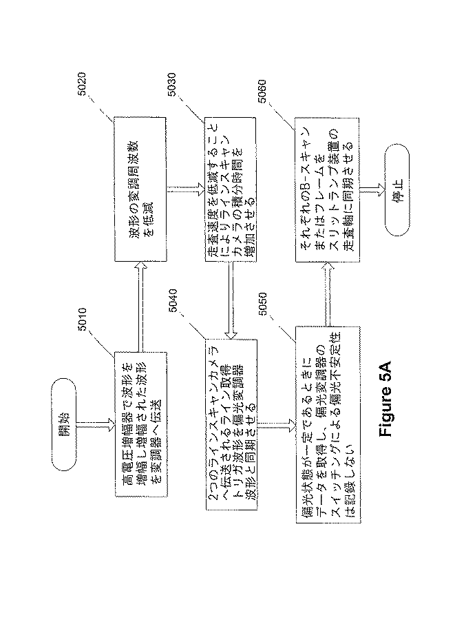
図7Aは、本発明の具体例による1つの偏光チャネル用の例示的な分光計の構成を示している。格子定数f=1/Δxを有する回折格子DG(7000)を提供可能である。又、この例示的な構成内に、焦点距離Fを有する合焦レンズL(7010)を更に包含することも可能である。図7Aに示されているように、θiは、入射角であり、θdは、回折角である。更には、λcは、角度θcにおいて回折され、合焦レンズLを通じて真っ直ぐに伝播し、CCD(7020)アレイの中心(x=0)から距離xoにおける画素上のCCD(7020)上に入射する中央波長を表している。Dは、格子(7000)と合焦レンズ(7010)の間の距離を表しており、dFは、レンズ(7010)の焦点面からのCCD(7020)の小さな変位を表している。この長手方向の変位dFは、合焦レンズ(7010)の焦点距離のわずかなチューニングに類似したものであってよい(又は、これに実質的に等価なものであってよい)。従って、Fは、較正パラメータと見なすことが可能である。その他の較正パラメータは、入射角θi、中央波長λc、及びCCD(7020)の横方向のシフトx0である。 FIG. 7A shows an exemplary spectrometer configuration for one polarization channel according to an embodiment of the invention. A diffraction grating DG (7000) having a grating constant f = 1 / Δx can be provided. It is also possible to further include a focusing lens L (7010) having a focal length F in this exemplary configuration. As shown in FIG. 7A, θ i is the angle of incidence and θ d is the diffraction angle. Furthermore, λ c is diffracted at an angle θ c and propagates straight through the focusing lens L, onto the CCD (7020) on the pixel at a distance x o from the center (x = 0) of the CCD (7020) array. It represents the incident central wavelength. D represents the distance between the grating (7000) and the focusing lens (7010), and dF represents the small displacement of the CCD (7020) from the focal plane of the lens (7010). This longitudinal displacement dF may be similar to (or substantially equivalent to) a slight tuning of the focal length of the focusing lens (7010). Therefore, F can be considered as a calibration parameter. Other calibration parameters are the incident angle θ i , the central wavelength λ c , and the lateral shift x 0 of the CCD (7020).
前述の図7Aに図示されている例示的な2つの偏光チャネルの構成においては、合焦レンズの後にビームスプリッタを提供可能であるため、入射角θi及び中央波長λcは、偏光チャネルについて実質的に同一であってよく、且つ、光学経路は、PBSまで共通であってよい。2つのLSCの変位に関係し得るパラメータ(F及びxo)は、好ましくは、互いに異なる必要がある。従って、例えば、θi、λc、F1、F2、xo1、及びxo2などの特定数の独立した較正パラメータが存在可能である。 In the exemplary two polarization channel configuration illustrated in FIG. 7A above, a beam splitter can be provided after the focusing lens, so that the incident angle θ i and the center wavelength λ c are substantially equal for the polarization channel. And the optical path may be common to the PBS. The parameters (F and xo) that can be related to the displacement of the two LSCs should preferably be different from each other. Thus, there can be a specific number of independent calibration parameters such as, for example, θ i , λ c , F 1 , F 2 , x o1 , and x o2 .
本発明の別の具体例による非偏光検出型システムにおける較正パラメータを判定するための本発明の例示的な実施例による例示的な手順が図7Bのフローチャートに示されており、以下、これについて説明する。 An exemplary procedure according to an exemplary embodiment of the present invention for determining calibration parameters in a non-polarization detection type system according to another embodiment of the present invention is shown in the flowchart of FIG. 7B, which will be described below. To do.
まず、段階7050において、基準アーム内の基準ミラーのいくつかの位置について2つのLSC上の強度プロファイルを記録する。段階7055において、サンプルアームは、水が充填された眼のモデル内がミラーを含むことにより、患者の計測をシミュレートしている。スペクトルを波長空間内、次いで、k空間内においてマッピング可能であり(段階7060)、且つ、k空間内のスペクトルのフーリエ変換としてコヒーレンス関数を取得可能である(段階7065)。段階7075において、基準アーム内のミラーの位置とは無関係に複素フーリエ変換の位相が一定になる時点まで較正パラメータをチューニング可能である。この位相項は、前述の患者の計測における分散補償のために使用可能である。
First, in
更には、段階7070において概略的なアライメントを実行可能であり、これは、データ取得段階7075の前に実行可能である。基準アーム信号を両方のカメラ上において極大化させている。2つのカメラを互いにアライメントさせるために、非複屈折スキャッタリングサンプル(顕微鏡カバースリップのスタックや均一散乱媒質など)を画像生成可能であり、且つ、リアルタイム偏光処理を実行することにより、例えば、大量の人工的な複屈折を視覚的に除去可能である。これは、本発明によるシステムの具体例によって計測される観察された複屈折が、小さくなるか、或いは、場合によっては、無視可能になる時点まで、ビームに対して垂直に1つのカメラの場所を移動させることにより、実行可能である。これにより、1つのカメラの他方のものに対する特定のアライメント(即ち、2つのラインスキャンカメラの対応する画素上における入射波長)を近似的又は粗く同一化することが可能であることを保証可能である。
Furthermore, a rough alignment can be performed in
第2に、マッピングパラメータの更に慎重な再較正を段階7080において実行可能である。これは、例えば、先程の基準アーム内のミラーの位置とは無関係な複素フーリエ変換の一定位相の条件以外の(又は、これに加えて)様々なメリット関数を最適化することにより、実現可能である。1つのこのような例示的な関数(例えば、Stokesベクトル)は、分光計に入射する光の偏光状態に依存可能である。ストークスベクトルは、J. F. de Boer他による「Determination of the depth−resolved Stokes parameters of light backscattered from turbid media by use of polarization−sensitive optical coherence tomography」(Optics Letters、1999年、第24(5)巻、300〜302頁)に記述されているように判定可能である。これらの較正パラメータは、計測された偏光状態が基準アーム内のミラーの位置とは無関係に一定になるように最適化可能である。2つのカメラ用の較正パラメータ及び位相係数の組は、患者の計測におけるスペクトルの正しいマッピング及び分散補償のために使用可能である。
Second, a more careful recalibration of the mapping parameters can be performed at
本発明の別の具体例によれば、段階7070を参照して先程説明した概略的なアライメントを実行する必要はない。2つのカメラ用のマッピングパラメータを適切に較正することにより、人工的な複屈折の出現を除去可能である。但し、段階7070を参照して先程説明した概略的なアライメントを伴わない場合には、x0などのパラメータの変化範囲が大きなものになる可能性がある。従って、概略的なアライメントは、最適化プロセスを更に容易且つ有益なものにすることができる。 According to another embodiment of the present invention, it is not necessary to perform the general alignment described above with reference to step 7070. Appropriate calibration of the mapping parameters for the two cameras can eliminate the appearance of artificial birefringence. However, if not accompanied by schematic alignment described earlier with reference to step 7070, there is a possibility that the range of variation of parameters such as x 0 becomes large. Thus, rough alignment can make the optimization process easier and more beneficial.
(被検者に対する例示的且つ実験的な計測手順)
ヘルシンキ宣言の教義に基づいたプロトコルに従って特定の実験を実行した。この実験のために、一人の健康なボランティアと7人の緑内障患者を動員した。様々な開放隅角度緑内障の段階を有する患者(原発性、色素性、及び擬似剥離形態)が得られ、且つ、患者が研究に対する適格性を有しているかどうかを判定した。インフォームドコンセントを付与し、且つ、患者が研究に参加するための適格性を有していることを判定した後に、緑内障患者の適格性を有する眼をフェニレフリン塩酸塩5.0%及びトロピカミド0.8%によって散瞳させた。本発明によるシステム、構成、及び方法の具体例を使用することにより、動員されたすべての被検者について計測を実行した。
(Example and experimental measurement procedure for the subject)
Specific experiments were performed according to a protocol based on the doctrine of the Declaration of Helsinki. For this experiment, one healthy volunteer and seven glaucoma patients were mobilized. Patients with various stages of open-angle glaucoma (primary, pigmented, and pseudo-exfoliated forms) were obtained and it was determined whether the patient was eligible for the study. After giving informed consent and determining that the patient is eligible to participate in the study, the eligible eyes of glaucoma patients are treated with phenylephrine hydrochloride 5.0% and tropicamide 0. Mydriasis were 8%. Measurements were performed on all mobilized subjects by using specific examples of systems, configurations, and methods according to the present invention.
(健康な被検者)
B. Cense他による「In vivo depth−resolved birefringence measurements of the human retinal nerve fiber layers by polarization−sensitive optical coherence tomography」(Opt. Lett.、2002年、第27(18)巻、1610〜1612頁)、B. Cense他による「In vivo birefringence and thickness measurements of the human retinal nerve fiber layer using polarization−sensitive optical coherence tomography」(Journal of Biomedical Optics、2004年、第9(1)巻、121〜125頁)、及びB. Cense他により「Thickness and birefringence of healthy retinal nerve fiber layer tissue measured with polarization−sensitive optical coherence tomography」(Investigative Ophthalmology & Visual Science、2004年、第45(8)巻、2606〜2612頁)に記述されている従来技術による偏光感受型時間ドメインシステム、並びに、N. Nassif他による「In vivo human retinal imaging by ultrahigh−speed spectral domain optical coherence tomography」(Optics Letters、2004年、第29(5)巻、480〜482頁)、N. A. Nassif他による「In vivo high−resolution video−rate spectral−domain optical coherence tomography of the human retina and optic nerve」(Optics Express、2004年、第12(3)巻、367〜376頁)、及びB. Cense他による「Ultrahigh−resolution high−speed retinal imaging using spectral−domain optical coherence tomography」(Optics Express、2004年)に記述されているスペクトルドメインシステムの両方により、比較のために、健康なボランティアの画像を予め生成した。
(Healthy subject)
B. Cens et al., “In vivo depth-resolved birefringence measurement of the the human reverberant fiber layered by biot. 16th year, p. 20th, p. Cens et al., “In vivo birefringence and thickness measurements of the human retinal nerve fibre layer ic. Cense the other by the "Thickness and birefringence of healthy retinal nerve fiber layer tissue measured with polarization-sensitive optical coherence tomography" has been described in (Investigative Ophthalmology & Visual Science, 2004 years, the first 45 (8), pp. 2606 to 2612) A polarization sensitive time domain system according to the prior art; Nassif et al. “In vivo human imaging by ultrahigh-speed spectral domain optical coherence tomography” (Optics Letters, 2004, Vol. 29-48). A. Nassif et al., “In vivo high-resolution video-rate spectral-domain optical coherence to the human of the human retina and optical nr., P.3, Op.6, 37”. Censé et al., "Ultrahigh-resolution high-speed repetitive imaging using spectral-domain optical coherence tomography" for the spectrum of the system by the comparison of the spectrum by the volunteers (Optics Express, 2004). Pre-generated.
この実験においては、ボランティアの散瞳されていない右眼上に入射する光のパワーは、470μWに等しかった。視神経乳頭の周辺において2つの異なるタイプのスキャンを実行した。同心円形スキャン(1.5〜2.6mmの半径間において等距離に離隔した1000個のAラインの12回の円形スキャン)によって1つのデータセットを生成し、6.3x6.4mmのエリアをカバーする500個のAラインの250回のラインスキャンにより、もう1つのデータセットを生成した。データは、1つのAライン当たりに33マイクロ秒又は132マイクロ秒のいずれかの蓄積時間において取得した。最後のセットにおいては、例示的なシステムの動作速度を4分の1に低減することにより、感度を4倍に改善した。この設定は、依然として、時間ドメインの計測と比べて、45倍高速であり、この結果、12回の円形スキャンにおいて、合計計測時間が72秒から1.6秒に低減された。調査対象の眼は、固定スポットによって安定化させた。 In this experiment, the power of light incident on the volunteer's non-mydriatic right eye was equal to 470 μW. Two different types of scans were performed around the optic disc. Generate one data set by concentric circular scan (12 circular scans of 1000 A lines equidistantly spaced between radii of 1.5-2.6mm), covering an area of 6.3x6.4mm Another data set was generated by 250 line scans of 500 A lines. Data was acquired at an accumulation time of either 33 or 132 microseconds per A line. In the last set, the sensitivity was improved by a factor of four by reducing the operating speed of the exemplary system by a factor of four. This setting was still 45 times faster than time domain measurements, resulting in a total measurement time reduced from 72 seconds to 1.6 seconds in 12 circular scans. The eye to be investigated was stabilized by a fixed spot.
(緑内障患者)
緑内障患者の場合には、眼に入射するパワーは500μW未満であった。患者が1つの眼によってしか見ることができない場合には、視力を欠いた眼の画像を生成した。画像生成対象の眼は、スプリットランプシステムの内部固定ライトによって安定化させた。この光を見ることができない患者の反対の眼には、外部固定ライトを使用した。33及び132マイクロ秒の蓄積時間を有する1000個のAラインの円形スキャンを実行した。更には、330マイクロ秒の蓄積時間により、これらの患者のいくつかの眼の画像を生成した。更には、1つのAライン当たりに132マイクロ秒において、線形スキャン(1000個のAラインの200回のスキャン(6.4x6.4mm))を実行した。
(Glaucoma patients)
In the case of glaucoma patients, the power incident on the eye was less than 500 μW. When the patient could only see with one eye, an eye image lacking vision was generated. The eye for image generation was stabilized by the internal fixed light of the split lamp system. An external fixed light was used on the opposite eye of the patient who cannot see this light. A circular scan of 1000 A lines with 33 and 132 microsecond accumulation times was performed. Furthermore, images of several eyes of these patients were generated with an accumulation time of 330 microseconds. In addition, a linear scan (200 scans of 1000 A lines (6.4 × 6.4 mm)) was performed at 132 microseconds per A line.
(例示的なデータ分析)
偏光分析は、いくつかの手順から構成されていた。第1の例示的な手順においては、分光計を前述のように較正した。計測されたスペクトルを、波長空間に、次いで、k空間に対してマッピングするべく、構成パラメータを使用した。更には、R. Chan他による「Anisotropic edge−preserving smoothing in carotid B−mode ultrasound for improved segmentation and intima−media thickness measurement」(Computer in Cardiology、Cambridge, MA、IEEE、2000年)に記述されているように、それぞれのカメラ用に判定された位相曲線を使用することにより、眼及び干渉計内の色分散を補償した。データをz空間にフーリエ変換した後に、M. C. Pierce他による「Simultaneous intensity, birefringence, and flow measurements with high−speed fiber−based optical coherence tomography」(Optics Letters、2002年、第27(17)巻、1534〜1536頁)に記述されているように、深さ分解ストークスパラメータを判定した。第1の深さ分解ストークスパラメータは、構造強度(例えば、深さ分解反射率)に対応している。R. Chan他による「Anisotropic edge−preserving smoothing in carotid B−mode ultrasound for improved segmentation and intima−media thickness measurement」(Computer in Cardiology、Cambridge, MA、IEEE、2000年)に記述されているように、このデータから網膜神経線維層の上部及び下部境界を判定した。偏光分析においては、C. E. Saxer他による「High−speed fiber−based polarization−sensitive optical coherence tomography of in vivo human skin」(Optics Letters、2000年、第25(18)巻、1355〜1357頁)、B. Cense他による「In vivo depth−resolved birefringence measurements of the human retinal nerve fiber layer by polarization−sensitive optical coherence tomography」(Opt. Lett.、2002年、第27(18)巻、1610〜1612頁)、B. Cense他による「In vivo birefringence and thickness measurements of the human retinal nerve fiber layer using polarization−sensitive optical coherence tomography」(Journal of Biomedical Optics、2004年、第9(1)巻、121〜125頁)、及びB. Cense他により「Thickness and birefringence of healthy retinal nerve fiber layer tissue measured with polarization−sensitive optical coherence tomography」(Investigative Ophthalmology & Visual Science、2004年、第45(8)巻、2606〜2612頁)に記述されているように、正規化された表面ストークスベクトルを特定の深さにおける正規化されたストークスベクトルと比較することにより、深さ分解位相遅延を判定した。
(Example data analysis)
Polarization analysis consisted of several procedures. In the first exemplary procedure, the spectrometer was calibrated as described above. Configuration parameters were used to map the measured spectrum to wavelength space and then to k-space. Furthermore, R.M. Chan et al., “Anisotropic edge-preserving smoothing in carrotid, B-mode ultrasound for improvised segmentation and intima-media, as well as Emerging By using the phase curve determined for the chromatic dispersion in the eye and interferometer. After Fourier transforming the data to z-space, M.M. C. Pierce et al., “Simultaneous intensity, birefringence, and flow measurements with high-speed fibre-based optical coherence tomography, vol. 15 to p. 27, Opt. Depth-resolved Stokes parameters were determined. The first depth-resolved Stokes parameter corresponds to the structural strength (eg, depth-resolved reflectivity). R. Chan, et al. “Anisotropic edge-preserving smoothing in carrotid B-mode ultrasound for improvised segmentation and intima-media information,” The upper and lower boundaries of the retinal nerve fiber layer were determined. In ellipsometry, C.I. E. Saxer et al., “High-speed fiber-based polarization-sensitive optical coherence of in vivo human skin” (Optics Letters, 2000, 135, 18). Cens et al., “In vivo depth-resolved birefringence measurement measurements of the human retin erive berber ly entr ent er. Cens et al., “In vivo birefringence and thickness measurements of the human retinal nerve fibre layer ic. Cense the other by the "Thickness and birefringence of healthy retinal nerve fiber layer tissue measured with polarization-sensitive optical coherence tomography" has been described in (Investigative Ophthalmology & Visual Science, 2004 years, the first 45 (8), pp. 2606 to 2612) As such, the depth-resolved phase delay was determined by comparing the normalized surface Stokes vector with the normalized Stokes vector at a particular depth.
健康なボランティアから取得されたデータについては、表面ストークスベクトルを自動的に検出された表面下方の10μmとなるように選択し、緑内障の患者の場合には、正確なデータ抽出のために可能な限り多くのポイントを保持するべく、3μmの値を選択した。移動平均フィルタを使用することにより、スペックル雑音の影響を低減した。水平方向においては、20を上回る数のAラインを平均し、垂直方向においては、3を上回る数のポイントを平均した(これは、10μmに対応している)。網膜神経線維層組織の厚さ及び複屈折をセクタ及び半径の関数として計測した。それぞれの円形スキャンを7.2°の50個のセクタに分割した。この50個のセクタは、時間ドメインデータに使用された48個のセクタに略マッチングしていた。 For data obtained from healthy volunteers, the surface Stokes vector is chosen to be 10 μm below the automatically detected surface, and in the case of glaucoma patients, as much as possible for accurate data extraction A value of 3 μm was selected to hold many points. The effect of speckle noise was reduced by using a moving average filter. In the horizontal direction, more than 20 A-lines were averaged, and in the vertical direction, more than 3 points were averaged (this corresponds to 10 μm). Retinal nerve fiber layer tissue thickness and birefringence were measured as a function of sector and radius. Each circular scan was divided into 50 sectors of 7.2 °. The 50 sectors substantially matched the 48 sectors used for time domain data.
線形スキャンによって取得されたデータセットを、眼底カメラ、スキャニングレーザー検眼鏡、又はスキャニングレーザー偏光計のいずれかによって生成されたものに実質的に等価である表面画像として処理した。これは、1つのAライン当たりの強度値をそれぞれの深さプロファイルに沿った1つの統合された反射率に対応する1つの値に合計することにより、実行された。例えば、3次元容積データセットを眼底画像として見える2次元画像に投影可能である。 The data set acquired by the linear scan was processed as a surface image that is substantially equivalent to that generated by either a fundus camera, a scanning laser ophthalmoscope, or a scanning laser polarimeter. This was done by summing the intensity values per A-line into one value corresponding to one integrated reflectivity along each depth profile. For example, a three-dimensional volume data set can be projected onto a two-dimensional image that appears as a fundus image.
(例示的な実験結果)
(健康な被検者から得られた結果)
本発明の具体例を使用することにより、眼底に似た画像として処理された線形スキャンの組(7.5kHzにおいて取得された6.4x6.4mmの500x250データポイント)が図8に示されている。具体的には、図8は、取得された三次元容積セットから再構築された視神経乳頭の例示的な擬似眼底画像を示している。白の円は、最小及び最大直径円形スキャンの概略的な位置を示している。上部側又は下部側エリア内において視神経から外に分岐している大きな血管を観察可能である。
(Example experimental results)
(Results obtained from healthy subjects)
By using an embodiment of the present invention, a set of linear scans (6.4 × 6.4 mm 500 × 250 data points acquired at 7.5 kHz) processed as a fundus-like image is shown in FIG. . Specifically, FIG. 8 shows an exemplary simulated fundus image of the optic disc reconstructed from the acquired three-dimensional volume set. White circles indicate the approximate location of the minimum and maximum diameter circular scans. Large blood vessels branching out from the optic nerve in the upper side or lower side area can be observed.
例えば、30kHz及び7.5kHzにおいて実行された円形スキャンを分析し、互いに比較した。7.5kHzのデータセットは、相対的に高い信号対雑音比(〜41dB対〜36dB)を示しており、顕著なモーションアーチファクトを含んではいなかった。図9は、40歳の健康なボランティアの散瞳されていない右眼の円形スキャンにより、7.5kHzのAラインレートにおいて取得された健康なボランティアの視神経乳頭周辺の円形スキャンの構造強度画像を示している。図9に示されているように、眼内の位置には、側頭部側(T)、上部側(S)、鼻側(N)、下部側(I)というラベルが付与されている。画像のサイズは、深さ0.96mmx幅12.6mmであり、これは、明瞭性のために、垂直方向において4倍に拡大されている。画像は、リアライメントされておらず、従って、視神経乳頭周辺の組織の真の形状を示している。ノイズフロアより上の画像のダイナミックレンジは、38.5dBであった。画像の最上部の下の水平ラインは、軸上にないラインスキャンカメラ内の電気雑音によって引き起こされたものである。 For example, circular scans performed at 30 kHz and 7.5 kHz were analyzed and compared to each other. The 7.5 kHz data set showed a relatively high signal-to-noise ratio (˜41 dB vs. −36 dB) and did not contain significant motion artifacts. FIG. 9 shows a structural intensity image of a circular scan around the optic nerve head of a healthy volunteer acquired at a 7.5 kHz A-line rate by a circular scan of the non-mydriatic right eye of a 40 year old healthy volunteer. ing. As shown in FIG. 9, labels in the eye are labeled as temporal side (T), upper side (S), nose side (N), and lower side (I). The size of the image is 0.96 mm deep x 12.6 mm wide, which is magnified four times in the vertical direction for clarity. The image is not realigned and thus shows the true shape of the tissue around the optic disc. The dynamic range of the image above the noise floor was 38.5 dB. The horizontal line below the top of the image is caused by electrical noise in the line scan camera that is not on axis.
画像のダイナミックレンジは、38.5dBである(同一データセット内において、最大で44dBのダイナミックレンジを有する画像が見出された)。強力な反射が図9内の黒い画素によって表されている。この画像は、明瞭性のために、垂直方向に拡大されている。B. Cense他による「Thickness and birefringence of healthy retinal nerve fiber layer tissue measured with polarization−sensitive optical coherence tomography」(Investigative Ophthalmology & Visual Science、2004年、第45(8)巻、2606〜2612頁)に記述されているように、上部側(F)及び下部側(I)エリアは、相対的に厚いRNFL組織を含んでいる。 The dynamic range of the image is 38.5 dB (images with a dynamic range of up to 44 dB were found in the same data set). Strong reflection is represented by the black pixels in FIG. This image is magnified in the vertical direction for clarity. B. Cense et al., "Thickness and birefringence of healthy retinal nerve fiber layer tissue measured with polarization-sensitive optical coherence tomography" has been described in (Investigative Ophthalmology & Visual Science, 2004 years, the first 45 (8), pp. 2606 to 2612) As such, the upper (F) and lower (I) areas contain relatively thick RNFL tissue.
両方のデータセットを分析することにより、セクタ及び半径の関数として厚さ及びDPPR/UD(Double−Pass Phase retardation per unit)を比較した。30kHzにおいて取得されたデータセットを、7.5kHzにおいて取得されたもの、並びに、256Hzにおいて時間ドメインシステム内において以前に取得されたものと比較した。図11A〜図11Fは、これらの例示的な計測値(例えば、異なる蓄積時間におけるRNFLの厚さ及びDPPR/UD計測値)のグラフを示している。例えば、図11A及び図11Bは、7.5kHzにおいて取得されたデータのグラフを示しており、図11C及び図11Dは、30kHzにおいて取得されたものを示している。時間ドメインのOCTシステムによって256Hzにおいて取得された図11E及び図11Fは、比較を目的として示されている。図11A、図11C、及び図11Eに示されている厚さのグラフは、類似した形態となっており、二重こぶのパターンを有しており、且つ、上部側(S)及び下部側(I)において相対的に高い値を有している。上部側のエリア内においては、相対的に小さな二重こぶのパターンを図11Cにおいて観察可能である。DPPR/UDのグラフも類似した形態となっており、上部側及び下部側において大きな値を有している。平均値の周辺における計測ポイント(例えば、ラインによって接続されているもの)の広がりは、恐らくは、図11Fに示されている時間ドメインデータにおけるよりも、図11B及び図11Dに示されているスペクトルドメインデータにおいて、相対的に大きいであろう By analyzing both data sets, the thickness and DPPR / UD (Double-Pass Phase reversion per unit) as a function of sector and radius were compared. Data sets acquired at 30 kHz were compared to those acquired at 7.5 kHz as well as those previously acquired in the time domain system at 256 Hz. 11A-11F show graphs of these exemplary measurements (eg, RNFL thickness and DPPR / UD measurements at different accumulation times). For example, FIGS. 11A and 11B show graphs of data acquired at 7.5 kHz, and FIGS. 11C and 11D show those acquired at 30 kHz. FIGS. 11E and 11F acquired at 256 Hz by the time domain OCT system are shown for comparison purposes. The thickness graphs shown in FIGS. 11A, 11C, and 11E are similar in shape, have a double hump pattern, and have an upper side (S) and a lower side ( It has a relatively high value in I). Within the upper area, a relatively small double hump pattern can be observed in FIG. 11C. The DPPR / UD graph has a similar form and has large values on the upper side and the lower side. The spread of measurement points around the mean value (eg, connected by a line) is probably the spectral domain shown in FIGS. 11B and 11D rather than in the time domain data shown in FIG. 11F. Will be relatively large in the data
以下、側頭部側のセクションの計測から開始して、図10A及び図10B内に示されているデータから取得された1つのセクタにわたって平均化されたスペクトルドメインのOCT計測について説明する、具体的には、図10Aは、本発明の具体例による構成、システム、及び/又は方法を使用して生成されたONHに対して側頭部側であるセクタの厚さ及DPPR(Douple−Pass Phase Retardation)を示す第1の模範的なグラフを示している。図10Bは、本発明の具体例による構成、システム、及び/又は方法を使用して生成されたONHに対して上部側であるセクタの厚さ及びDPPRの第1の例示的なグラフを示している。7.5kHzのAラインレートにより、ONHに対して側頭部側であるセクタ(A)及び上部側であるセクタ(B)の厚さ(例えば、破線として示されているもの)及びDPPR(例えば、実線として示されているもの)のグラフを取得した。このデータを20個のAライン又は7.5°のセクタにわたって平均した。RNFLに属するDPPRデータは、最小二乗線形フィットによってフィッティング可能である。式中の傾きは、DPPR/UDを表している。垂直ラインは、強度及びDPPRデータから判定されるRNFLの推定境界を示している。150μmを上回る深さにおけるDPPRにおける増大は、RNFLとRPEの間の低信号によって引き起こされている。 The following describes the spectral domain OCT measurement averaged over one sector obtained from the data shown in FIGS. 10A and 10B, starting with the measurement of the temporal section. FIG. 10A illustrates the sector thickness and DPPR (Double-Pass Phase Retardation) for the temporal side of ONH generated using an arrangement, system, and / or method according to embodiments of the invention. ) Shows a first exemplary graph. FIG. 10B shows a first exemplary graph of sector thickness and DPPR that is the upper side for ONH generated using configurations, systems, and / or methods according to embodiments of the invention. Yes. With the A line rate of 7.5 kHz, the thickness of the sector (A) on the temporal side and the sector (B) on the upper side with respect to ONH (for example, shown as a broken line) and DPPR (for example, , What is shown as a solid line). This data was averaged over 20 A-lines or 7.5 ° sectors. DPPR data belonging to RNFL can be fitted by a least square linear fit. The slope in the equation represents DPPR / UD. The vertical line indicates the estimated RNFL boundary determined from the intensity and DPPR data. The increase in DPPR at depths above 150 μm is caused by a low signal between RNFL and RPE.
例えば、側頭部側のエリア内においては、RNFLは薄く、相対的に小さなDPPR/UD値を取得可能である。上部側のセクタは、相対的に大きな複屈折を有する相対的に厚いRNFL組織を含んでいる。鼻側のプロットは、薄いRNFL及び小さな複屈折を示しており、下部側のプロットは、大きなDPPR/UD値を有する厚いRNFLを示している。厚さの値を半径及びセクタの関数としてプロットし、1つの半径において取得されたデータポイントをラインによって接続した。ラインの太さは、スキャンの半径をしており、スキャンのラインが太いほど、視神経乳頭に対して相対的に近接している。又、DPPR/UDの値も半径及びセクタの関数としてプロットしており、特定の半径におけるデータポイントは、同一のシンボルを保持している。1セクタ当たりの平均EPPR/UD値を判定し、1セクタ当たりの平均値をラインによって接続した。平均の標準誤差(Standard error:SE)を判定し、これを誤差バーによってグラフ内に表している。 For example, in the temporal area, the RNFL is thin and a relatively small DPPR / UD value can be acquired. The upper sector contains relatively thick RNFL tissue with relatively large birefringence. The nasal plot shows thin RNFL and small birefringence, and the bottom plot shows thick RNFL with large DPPR / UD values. Thickness values were plotted as a function of radius and sector, and data points acquired at one radius were connected by a line. The thickness of the line is the radius of the scan. The thicker the scan line, the closer to the optic nerve head. DPPR / UD values are also plotted as a function of radius and sector, with data points at a particular radius holding the same symbol. The average EPPR / UD value per sector was determined, and the average value per sector was connected by a line. An average standard error (SE) is determined and represented in the graph by an error bar.
図11A〜図11Fの厚さのグラフを比較することにより、上部側及び下部側において大きな値を有する類似した傾向を観察可能である。これらのエリア内の相対的に大きな厚さの値は、鋭い神経線維束の存在によって説明可能であり、これらは、中心窩に向かって分岐している。厚さの計測値の差は、操作者によるデータの主観的な解釈に帰することができる。本発明の模範的な一実施例による自動的な画像分析手順により、客観性及び分析を改善可能である。DPPR/UDのグラフも、上部側及び下部側において大きな値を有する同様の傾向を示している。7.5kHzにおいて得られたSD−OCTのデータ結果のほうが、TD−OCTのデータ結果と、より良好にマッチング可能である。側頭部側の値は、両方のSD−OCTデータセット内において増大可能であり、これらの結果は、TD−OCTセットアップの場合には、小さい。図11A〜図11Fのすべてのグラフにおいて、下部側及び上部側の値が相対的に大きいという一般的な傾向を観察可能である。この被検者についてPS−SD−OCTによって計測された最大平均DPPR/UD値は、約0.45°/μmであり、最小平均値は、約0.2°/μmに等しい。これらの値は、840nmにおいて計測されたそれぞれ5.4x10-4及び2.4x10-4の複屈折に略等しいであろう。 By comparing the thickness graphs of FIGS. 11A-11F, it is possible to observe a similar trend with large values on the upper and lower sides. The relatively large thickness values in these areas can be explained by the presence of sharp nerve fiber bundles, which branch off towards the fovea. The difference in thickness measurements can be attributed to the subjective interpretation of the data by the operator. An automatic image analysis procedure according to an exemplary embodiment of the present invention can improve objectivity and analysis. The DPPR / UD graph also shows a similar tendency with large values on the upper and lower sides. The SD-OCT data result obtained at 7.5 kHz can be better matched with the TD-OCT data result. The temporal value can be increased in both SD-OCT data sets, and these results are small for the TD-OCT setup. In all the graphs of FIGS. 11A to 11F, it is possible to observe a general tendency that the values on the lower side and the upper side are relatively large. The maximum average DPPR / UD value measured by PS-SD-OCT for this subject is about 0.45 ° / μm, and the minimum average value is equal to about 0.2 ° / μm. These values will be approximately equal to the birefringence of each measured 5.4 × 10 -4 and 2.4 × 10 -4 at 840 nm.
(健康な被検者から得られた例示的な結果の検討)
図11Fに示されている時間ドメインのDPPR/UDプロットを図11B及び図11Dに示されているスペクトルドメインプロットと比較すれば、スペクトルドメインのデータポイントは、相対的に大きな範囲にわたって散乱した状態で示されている。これは、部分的に、スペクトルドメインデータに使用した際の本発明のシステム、構成、及び方法の具体例の操作者による(自動スロープフィッティング手順の使用及び相対的に小さな数のAラインにわたる平均化に伴う)不完全な使用法に帰することができる。雑音の多い時間ドメイン計測の場合には、RNFLより下の平均DPPR値を使用することにより、DPPR/UDを算出した。平均DPPR値をRNFLの厚さによって除算することにより、DPPR/UDを算出可能である。スペクトルドメインの値の場合には、この手順により、データ上に存在している雑音とは無関係に、RNFLのDPPRデータポイントを通じてラインをフィッティング可能である。フィッティングするべき多数のデータポイントを有するRNFLの厚い部分の場合には、この例示的な手順は、恐らくは、信頼性の高い結果をもたらすであろう。
(Examination of exemplary results obtained from healthy subjects)
Comparing the time domain DPPR / UD plot shown in FIG. 11F with the spectral domain plots shown in FIGS. 11B and 11D, the spectral domain data points are scattered over a relatively large range. It is shown. This is partly due to the use of an embodiment of the inventive system, configuration and method when used for spectral domain data (use of an automatic slope fitting procedure and averaging over a relatively small number of A-lines. Can be attributed to incomplete usage. For noisy time domain measurements, DPPR / UD was calculated by using the average DPPR value below RNFL. By dividing the average DPPR value by the thickness of RNFL, DPPR / UD can be calculated. For spectral domain values, this procedure allows the line to be fitted through the RNFL DPPR data points regardless of the noise present on the data. In the case of a thick part of the RNFL with a large number of data points to be fitted, this exemplary procedure will probably yield reliable results.
(緑内障被検者の結果)
例示的なPS−SD−OCTシステム、構成、及び方法により、緑内障患者の画像を生成した。特定のデータセットは、分析するのに有益な信号対雑音比を具備していた。このデータセットは、81歳の白人女性の左眼から得られたものである。彼女は、6年前に白内障手術を経験している(これは、恐らくは、相対的に高い画像品質に結び付く)。彼女の最良に補正された視力は、20/20であり、内部固定スポットを使用することにより、眼を安定化させた。視野試験の結果は、上部側の視野欠陥を示しており、これは、下部側エリア内における相対的に薄い神経線維層を結果的にもたらすはずである(即ち、眼の視力に反比例可能である)。報告された視野欠陥は相対的に小さいものであった。図12は、この緑内障患者の視神経乳頭周辺の円形スキャンから取得された例示的な構造強度画像を示している。この画像は、緑内障によって引き起こされた相対的に薄い下部側の神経線維層(I)を示している。その他のエリアは、いずれも、変化のない状態において示されている。眼内の位置には、側頭部側(T)、上部側(S)、鼻側(N)、下部側(I)というラベルが付与されている。この画像のサイズは、0.96mm深さx12.6mm幅であり、且つ、これは、明瞭性のために、垂直方向において4倍に拡大されている。ノイズフロアよりも上の画像のダイナミックレンジは、37.4dBであり、Aラインは、7.5kHzにおいて取得している。この画像は、2mmの半径及び7.5kHzのAライン取得レートにおいて取得されたものである。
(Results of glaucoma subjects)
An image of a glaucoma patient was generated by an exemplary PS-SD-OCT system, configuration, and method. Certain data sets had a signal-to-noise ratio that was useful for analysis. This data set was obtained from the left eye of an 81 year old white female. She has experienced cataract surgery 6 years ago (which probably leads to a relatively high image quality). Her best corrected visual acuity was 20/20 and the eye was stabilized by using an internal fixation spot. The results of the visual field test show an upper visual field defect, which should result in a relatively thin nerve fiber layer in the lower area (ie, can be inversely proportional to eye vision) ). The reported visual field defects were relatively small. FIG. 12 shows an exemplary structural intensity image obtained from a circular scan around the optic disc of this glaucoma patient. This image shows a relatively thin lower nerve fiber layer (I) caused by glaucoma. All other areas are shown unchanged. Labels such as the temporal side (T), the upper side (S), the nose side (N), and the lower side (I) are assigned to the positions in the eye. The size of this image is 0.96 mm deep x 12.6 mm wide, and it has been enlarged four times in the vertical direction for clarity. The dynamic range of the image above the noise floor is 37.4 dB, and the A line is acquired at 7.5 kHz. This image was acquired at a radius of 2 mm and an A-line acquisition rate of 7.5 kHz.
健康な被検者内において実行されたスキャン(例えば、図9に示されている画像)と比較した場合に、RNFLと神経節細胞層の間のコントラスト(これは、RNFLの境界をなしている)は、それほど強力ではない。この患者の下部側(I)のRNFL組織は、健康な被検者の同じ下部側の組織と比べて薄くなっている。 Contrast between the RNFL and the ganglion cell layer (which bounds the RNFL when compared to a scan performed in a healthy subject (eg, the image shown in FIG. 9) ) Is not so powerful. The lower (I) RNFL tissue of this patient is thinner than the same lower tissue of a healthy subject.
図13Aは、本発明の具体例による構成、システム、及び/又は方法を使用して生成されたONHに対して側頭部側であるセクタの厚さ及びDPPRの第2の例示的なグラフを示しており、図13Bは、本発明の具体例による構成、システム、及び/又は方法を使用して生成されたONHに対して上部側であるセクタの厚さ及びDPPRの第2の例示的なグラフを示している。図13A及び図13Bに提供されているデータは、緑内障患者から得られたものである。RNFLに属するそれぞれのグラフ内のDPPRデータを最小二乗線形フィットによってフィッティングしている。式中のスロープは、DPPR/UDを表している。垂直ラインは、強度及びDPPRデータから判定されたRNFLの推定境界を示している。 FIG. 13A shows a second exemplary graph of sector thickness and DPPR that is temporally to ONH generated using an arrangement, system, and / or method according to embodiments of the invention. FIG. 13B shows a second exemplary sector thickness and DPPR that is the upper side for ONH generated using an arrangement, system, and / or method according to embodiments of the invention. The graph is shown. The data provided in FIGS. 13A and 13B was obtained from a glaucoma patient. DPPR data in each graph belonging to RNFL is fitted by a least square linear fit. The slope in the formula represents DPPR / UD. The vertical line indicates the estimated boundary of the RNFL determined from the intensity and DPPR data.
図12に示されている構造強度画像においては、(「I」というラベルが付与されている)下部側のエリア内において視野欠陥が観察された。図14は、緑内障患者の下部側のエリア内におけるこの視野欠陥内のセクタからのDPPRの結果(実線)及び厚さ(破線)のグラフを示している。RNFLは、相対的に薄い状態において示されているが、DPPR/UDは、大きな値に留まっている。 In the structural intensity image shown in FIG. 12, visual field defects were observed in the lower area (labeled “I”). FIG. 14 shows a graph of DPPR results (solid line) and thickness (dashed line) from a sector within this visual field defect in the lower area of the glaucoma patient. Although RNFL is shown in a relatively thin state, DPPR / UD remains large.
すべての半径においてすべてのセクタを分析した後に、2つのグラフ内において厚さ及びDPPR/UDのプロットを組み合わせた。例えば、図15Aに示されている厚さのグラフは、上部側のエリア内において計測される厚さが半径の関数として減少することを示している。B. Cense他による「Thickness and birefringence of healthy retinal nerve fiber layer tissue measured with polarization−sensitive optical coherence tomography」(Investigative Ophthalmology & Visual Science、2004年、第45(8)巻、2606〜2612頁)及びB. Cense他による「Thickness and birefringence of retinal nerve fiber layer of healthy and glaucomatous subjects measured with polarization sensitive optical coherence tomography」(Ophthalmic Technologies XIV、Proceedings of SPIE、第5314巻、2004年、179〜187頁)に記述されているように、この減少は、健康な被検者においても観察されている。下部側のエリア内においては、この半径の関数としての減少は、異なる半径の曲線がオーバーラップしているため、それほど明瞭ではないであろう。健康な被検者の厚さのグラフと比較した場合に、緑内障被検者の下部側のエリアは、相対的に薄くなっている。具体的には、上部側及び下部側のエリアの間の比率は、健康な被検者の場合と比べて、この緑内障患者の場合には、格段に大きくなっている。相対的に薄い下部側のエリアは、視野試験によって計測された視野欠陥と合致している。 After analyzing all sectors at all radii, the plots of thickness and DPPR / UD were combined in the two graphs. For example, the thickness graph shown in FIG. 15A shows that the measured thickness in the upper area decreases as a function of radius. B. Cense et al., "Thickness and birefringence of healthy retinal nerve fiber layer tissue measured with polarization-sensitive optical coherence tomography" (Investigative Ophthalmology & Visual Science, 2004 years, the first 45 (8), pp. 2606-2612) and B. Cense et al., "Thickness and birefringence of retinal nerve fiber layer of healthy and glaucomatous subjects measured with polarization sensitive optical coherence tomography" (Ophthalmic Technologies XIV, Proceedings of SPIE, the 5314 Volume, 2004, pp. 179-187) is described in the As can be seen, this decrease has also been observed in healthy subjects. Within the lower area, this decrease as a function of radius will not be as obvious as the curves of different radii overlap. When compared to the graph of healthy subject thickness, the lower area of the glaucoma subject is relatively thin. Specifically, the ratio between the upper and lower areas is much greater for this glaucoma patient than for a healthy subject. The relatively thin lower area coincides with the visual field defect measured by the visual field test.
図15Bに示されているDPPR/UDのグラフは、大きな上部側(S)における値を示している。また、鼻側(N)及び下部側(I)エリアの間においても、大きな値を取得可能であり、小さな値は、鼻側及び側頭部側のエリアにおいて発生している。側頭部側及び下部側エリアの間において落ち込みが明白である。スペクトルドメイン及び時間ドメインのOCTシステム及び手順の両方と共に使用する場合には、一般的な傾向は、健康な被検者において観察される傾向と類似している。 The DPPR / UD graph shown in FIG. 15B shows values on the large upper side (S). Also, a large value can be acquired between the nose side (N) and lower side (I) areas, and small values are generated in the nose side and temporal side areas. A depression is evident between the temporal and lower area. When used with both spectral and time domain OCT systems and procedures, the general trend is similar to that observed in healthy subjects.
健康な被検者からの結果の分析に基づいて、わずかに雑音が多いDPPRグラフの可能な影響を低減するべく、本発明の更なる具体例に従って別の平均化手順を開発した。例えば、この手順によれば、データを再度分析し、平均化フィルタを実装することにより、40個のAラインのStokesパラメータを平均化している。次いで、データをスキャン内の相対的に少ない数のデータポイントに対してマッピングすることにより、セクタの数を2分の1に減少させた。 Based on the analysis of results from healthy subjects, another averaging procedure was developed in accordance with a further embodiment of the present invention to reduce the possible effects of slightly noisy DPPR graphs. For example, according to this procedure, 40 A-line Stokes parameters are averaged by analyzing the data again and implementing an averaging filter. The number of sectors was then reduced by a factor of two by mapping the data to a relatively small number of data points in the scan.
図16Aは、緑内障患者のONHに対して鼻側であるエリアの厚さ(破線)及びDPPR(実線)のプロットを提供する例示的なグラフを示している。図16Bは、緑内障患者のONHに対して上部側であるエリアの厚さ及びDPPRのプロットを提供する例示的なグラフを示しており、且つ、図16Cは、緑内障患者のONHに対して下部側であるエリアの厚さ及びDPPRのプロットを提供する例示的なグラフを示している。これらのグラフは、図15A及び図15Bのグラフ内に表示されているものに類似したDPPR/UDを示している。これらのグラフの場合には、40個のAラインのStokesパラメータを平均化することにより、スペックル雑音の影響を低減している。これらのグラフを相対的に少ない数のAラインにわたって平均化された(図13A及び図13Bに示されている)同一患者のセクタグラフと比較すれば、これらの曲線のほうが、雑音が少なくなっている。すべてのセクタ及び半径の結果が図17A及び図17Bに示されている。具体的には、図17Aは、緑内障患者の神経線維層組織のRNFLの厚さを提供する例示的なグラフを示しており、図17Bは、緑内障患者の神経線維層組織のDPPR/UDの値を提供する例示的なグラフを示している。これらのグラフにおいては、40個のAラインからのStokesパラメータを平均化している。20個のAラインにわたって平均化された緑内障データにおいて観察可能であった傾向は、同一に留まっており、DPPR/UD値は、上部側及び下部側において大きくなっており、最も厚い組織は、上部側のエリア内に配置されている。この平均化手順は、データポイント内における広がりを低減しているが、全体的な傾向は、非常に類似した状態に留まっている。 FIG. 16A shows an exemplary graph that provides plots of the thickness (dashed line) and DPPR (solid line) of the area that is nasal to the ONH of glaucoma patients. FIG. 16B shows an exemplary graph that provides a plot of the thickness and DPPR of the upper area for ONH of glaucoma patients, and FIG. 16C shows the lower side of ONH for glaucoma patients. FIG. 6 shows an exemplary graph providing a plot of area thickness and DPPR that are These graphs show DPPR / UD similar to that displayed in the graphs of FIGS. 15A and 15B. In the case of these graphs, the effect of speckle noise is reduced by averaging the Stokes parameters of 40 A lines. Comparing these graphs with the same patient sector graph (shown in FIGS. 13A and 13B) averaged over a relatively small number of A-lines, these curves are less noisy. Yes. The results for all sectors and radii are shown in FIGS. 17A and 17B. Specifically, FIG. 17A shows an exemplary graph providing the RNFL thickness of nerve fiber layer tissue of glaucoma patients, and FIG. 17B shows the DPPR / UD value of nerve fiber layer tissue of glaucoma patients. 2 illustrates an exemplary graph that provides In these graphs, the Stokes parameters from 40 A lines are averaged. The trend that was observable in glaucoma data averaged over 20 A-lines remains the same, DPPR / UD values are higher on the upper and lower sides, and the thickest tissue is Located in the side area. This averaging procedure reduces the spread within the data points, but the overall trend remains very similar.
この患者についてPS−SD−OCTシステム及び手順によって計測された最大平均DPPR/UD値は、約0.4°/μmであり、最小平均値は、約0.15°/μmであろう。これらの値は、840nmにおいて計測されたそれぞれ4.8x10-4及び1.8x10-4の複屈折に略等しくなっている。 The maximum average DPPR / UD value measured by the PS-SD-OCT system and procedure for this patient will be about 0.4 ° / μm and the minimum average value will be about 0.15 ° / μm. These values are substantially equal to the birefringence of each measured 4.8 × 10 -4 and 1.8x10 -4 at 840 nm.
(緑内障被検者の結果の検討)
本発明の具体例によれば、緑内障の場合には、明確にアライメントされた複屈折性を有する神経線維が複屈折性の小さな無定形のグリア細胞によって置換されことになるため、RNFLの複屈折の減少が発生すると考えられる。緑内障患者の下部側のエリアは、緑内障の結果として相対的に薄くなるが、このエリア内のDPPR/UD値の大部分は、正常な状態で観察される。下部側及び側頭部側エリアの間の領域内に、わずかな落ち込みが存在しており、これは、何人かの健康な被検者においても観察可能であるが、鼻側及び下部側エリアの間には、正常な下部側の値が生じている。約0.4°/μmというピーク値は、上部側のエリア内におけるDPPR/UD値、並びに、健康な被検者の下部側及び上部側のエリアのものに非常に類似している。
(Examination of the results of glaucoma subjects)
According to an embodiment of the present invention, in the case of glaucoma, the birefringence of RNFL is replaced because the clearly aligned birefringent nerve fibers are replaced by amorphous glial cells with small birefringence. It is considered that a decrease in The lower area of glaucoma patients becomes relatively thin as a result of glaucoma, but most of the DPPR / UD values in this area are observed in a normal state. There is a slight depression in the area between the lower and temporal areas, which can be observed in some healthy subjects, but in the nasal and lower areas. In the meantime, a normal lower value is generated. The peak value of about 0.4 ° / μm is very similar to the DPPR / UD values in the upper area, as well as those in the lower and upper areas of healthy subjects.
下部側エリア内のRNFLの大部分は、75μmよりもわずかに厚いのみである。同一の信号対雑音比における時間ドメイン計測の場合には、DPPR/UD計測は、一般に、信頼性が高い。しかしながら、これらの計測は、健康な被検者から取得された計測よりも低い信号対雑音比において取得されている(図11B及び図11Dに示されている)。実際に、緑内障データの信号対雑音比は、健康な被検者からのデータと比べて、平均で約3dBだけ低くなっている。このような例示的な結果は、緑内障の1つのタイプを有する一人の緑内障患者から取得されたものであるが、これは、すべての緑内障患者について有用であろう。 Most of the RNFL in the lower area is only slightly thicker than 75 μm. In the case of time domain measurements at the same signal-to-noise ratio, DPPR / UD measurements are generally reliable. However, these measurements have been acquired at a lower signal to noise ratio than those obtained from healthy subjects (shown in FIGS. 11B and 11D). In fact, the signal-to-noise ratio of glaucoma data is on average about 3 dB lower than that from data from healthy subjects. Such exemplary results were obtained from a single glaucoma patient with one type of glaucoma, but this would be useful for all glaucoma patients.
更には、本発明の具体例によるいくつかの方法によって更に高い信号対雑音比(SNR)を実現可能である。まず、最初に、ソースアームパワーを増大させることにより、SNRを改善可能である。ANSI規格は、スキャニングビームについて、600μWを上回る大きなパワーの使用を提供している。7.5kHzの取得速度、9.4mmのスキャン長(最短半径によるスキャン)、及び1スキャン当たりに132msのスキャン時間において、パワーを15倍の約9mWまで増大可能である。更には、パワーを低減することなしに、スキャンレートを低減することも可能である。例えば、スキャンレートを約3kHzに低速化させることにより、信頼性の高いDPPR/UD結果を入手可能である。モーションアーチファクトが発生する可能性が高いため、緑内障患者の場合には、相対的に長い取得時間は、問題となろう。網膜トラッカは、このようなアーチファクトを回避可能であり、且つ、R. D. Ferguson他による「Tracking optical coherence tomography」(Optics letters、2004年、第29(18)巻、2139〜2141頁)に記述されているように、瞬きに起因して失われたエリアを自動的に再スキャンすることも可能である。健康な被検者におけるスペクトルドメイン計測は、時間ドメイン計測において取得されたものと良好にマッチングしているため、更なる選択肢は、緑内障を有する若い被検者に対して本発明による例示的な手順を実行することであろう。 Furthermore, even higher signal-to-noise ratios (SNR) can be achieved by several methods according to embodiments of the invention. First, the SNR can be improved by first increasing the source arm power. The ANSI standard provides for the use of large power above 600 μW for the scanning beam. With an acquisition speed of 7.5 kHz, a scan length of 9.4 mm (scan with the shortest radius), and a scan time of 132 ms per scan, the power can be increased by a factor of 15 to about 9 mW. Furthermore, the scan rate can be reduced without reducing the power. For example, a reliable DPPR / UD result can be obtained by reducing the scan rate to about 3 kHz. For glaucoma patients, a relatively long acquisition time may be a problem, as motion artifacts are likely to occur. The retinal tracker can avoid such artifacts, and R.I. D. As described in “Tracking optical coherence tomography” by Ferguson et al. (Optics letters, 2004, Vol. 29 (18), pp. 2139-2141), the area lost due to blinking is automatically reestablished. It is also possible to scan. Since spectral domain measurements in healthy subjects are well matched to those obtained in time domain measurements, a further option is an exemplary procedure according to the present invention for young subjects with glaucoma. Would do.
(例示的な実験の結論)
本発明の具体例によるスペクトルドメイン偏光検出型OCTシステム、構成、及び方法によって一人の健康な被検者について計測された健康なRNFL組織の複屈折は、スキャン半径の関数として一定であってよく、且つ、ONH周辺の位置の関数として変化可能であり、ONHに対して上部側及び下部側において高い値が生じている。一人の健康な被検者のONHの周囲における計測平均DPPR/UDは、0.20〜0.45°/μmの間において変化した。これらの値は、840nmにおいて計測された2.4x10-4及び5.4x10-4の複屈折に等しいものであってよい。
(Conclusion of exemplary experiment)
The birefringence of healthy RNFL tissue measured for a healthy subject by a spectral domain polarization-detected OCT system, configuration, and method according to embodiments of the present invention may be constant as a function of scan radius, Moreover, it can change as a function of the position around the ONH, and a high value is generated on the upper side and the lower side with respect to the ONH. The measured average DPPR / UD around ONH of one healthy subject varied between 0.20 and 0.45 ° / μm. These values can be equal to the birefringence of the measured 2.4 × 10 -4 and 5.4 × 10 -4 at 840 nm.
小さな視野欠陥を有する緑内障被検者における計測値は、緑内障に起因して、下部側のセクタ内において薄くなった神経線維層を示している。本発明の具体例による偏光感受型の計測値は、恐らくは、これらのセクタ内の神経線維層組織の一部が健康な組織と同程度に複屈折性を有していることを通知している。 Measurements in glaucoma subjects with small visual field defects show a thinned nerve fiber layer in the lower sector due to glaucoma. The polarization-sensitive measurements according to embodiments of the present invention probably indicate that some of the nerve fiber layer tissue in these sectors is as birefringent as healthy tissue. .
(例示的な使用法及びアプリケーション)
本発明によるシステム、構成、及び方法の具体例と共に使用可能である(又は、これらを内蔵可能である)特定の例示的なシステム、構成、製品、プロセス、サービス、手順、又は研究ツールは、(i)B. Cense他による「In vivo depth−resolved birefringence measurements of the human retinal nerve fiber layer by polarization−sensitive optical coherence tomography」(Opt. Lett.、2002年、第27(18)巻、1610〜1612頁)、B. Cense他による「In vivo birefringence and thickness measurements of the human retinal nerve fiber layer using polarization−sensitive optical coherence tomography」(Journal of Biomedical Optics、2004年、第9(1)巻、121〜125頁)、及びB. Cense他による「Thickness and birefringence of healthy retinal nerve fiber layer tissue measured with polarization−sensitive optical coherence tomography」(Investigative Ophthalmology & Visual science、2004年、第45(8)巻、2606〜2612頁)に記述されている緑内障の早期検出用のPS−SD−OCTシステム、(ii)角膜の複屈折計測値を入手するためのPS−SD−OCTシステム、(iii)B. H. Park他による「In vivo burn depth determination by high−speed fiber−based polarization sensitive optical coherence tomography」(journal of Biomedical Optics、2001年、第6(4)、474〜9頁)に記述された火傷深さ分析を提供するため、並びに、M. C. Pierce他による「Birefringence measurements in human skin using polarization−sensitive optical coherence tomography」(Journal of Biomedical optics、2004年、第9(2)巻、287〜291頁)及びM. C. Pierce他による「Advances in Optical Coherence Tomography Imaging for Dermatology」(J Invest Dermatology、2004年、第123(3)巻、458〜463頁)に記述された皮膚のコラーゲン含有量を計測することによる皮膚癌検出を実行するためのPS−SD−OCTシステム、(iv)冠状動脈のコラーゲン含有量を計測することによる心血管系疾病の光学的診断を実行するPS−SD−OCTシステム、(v)腫瘍及び癌組織の早期診断を実行するPS−SD−OCTシステム、及び/又は(vi)プラスチック、ガラス、及び組織などの散乱材料の品質管理用の計測を実行するPS−SD−OCTシステムを包含可能である(但し、これらに限定されない)。
(Example usage and application)
Certain exemplary systems, configurations, products, processes, services, procedures, or research tools that can be used with (or can incorporate) specific examples of systems, configurations, and methods according to the present invention are ( i) B. Cens et al., “In vivo depth-resolved birefringence measurement measurements of the human retin erive berber ly entr ent er. Cens et al., “In vivo birefringence and thickness measurements of the human retinal nerve fibre layer ic. Cense et al., "Thickness and birefringence of healthy retinal nerve fiber layer tissue measured with polarization-sensitive optical coherence tomography" has been described in (Investigative Ophthalmology & Visual science, 2004 years, the first 45 (8), pp. 2606 to 2612) PS-SD-OCT system for early detection of glaucoma, (ii) PS-SD-OCT system for obtaining birefringence measurements of the cornea, (iii) B. H. Park et al., “In vivo burn depth determination by high-speed fiber-based polarized optical coherence tomography” (Journal of Biomedics, p. 4) As well as M.S. C. Pierre et al., “Birfringence measurements in human skin using polarization-sensitive optical coherence tomography” (Journal of Biomedical optics, 2004, Vol. 9, pp. 29-29). C. Collagen content of skin as described by Pierce et al., “Advanced in Coherence Tomography Imaging for Dermatology” (J Invest Dermatology, 2004, 123 (3), 458-463) (Iv) PS-SD-OCT system for performing optical diagnosis of cardiovascular disease by measuring the collagen content of coronary arteries, (v) Tumor and cancer PS-SD-OCT system that performs early diagnosis of tissue and / or (vi) PS-SD-OCT system that performs measurements for quality control of scattering materials such as plastic, glass, and tissue (However, this Not limited to, et al).
以上は、本発明の原理を例示したものに過ぎない。本明細書の開示内容に鑑み、当業者には、記述されている実施例に対する様々な変更及び変形が明らかであろう。実際に、本発明の具体例による構成、システム、及び方法は、任意のOCTシステム、OFDIシステム、SD−OCTシステム又はその他の画像生成システム、並びに、例えば、2004年9月8日付けで出願された国際特許出願第PCT/US2004/029148号、2005年11月2日付けで出願された米国特許出願第11/266,779号、及び2004年7月9日付けで出願された米国特許出願第10/501,276号に記述されているものと共に使用可能であり、これらの開示内容は、本引用により、そのすべてが本明細書に包含される。従って、当業者であれば、本発明の原理を実施すると共に本発明の精神及び範囲内に属する(但し、本明細書には明示的に図示及び記述されてはいない)多数のシステム、構成、及び方法を考案可能であることを理解されたい。更には、引用によって本明細書に明示的に包含されていない場合にも、従来技術における知識は、そのすべてが本明細書に明示的に包含されている。本明細書において参照されたすべての文献は、引用により、そのすべてが本明細書に包含されている。 The foregoing is merely illustrative of the principles of the present invention. Various modifications and variations to the described embodiments will be apparent to those skilled in the art in view of the disclosure herein. Indeed, configurations, systems, and methods according to embodiments of the present invention are filed on any OCT system, OFDI system, SD-OCT system or other image generation system, as well as, for example, dated September 8, 2004. International Patent Application No. PCT / US2004 / 029148, US Patent Application No. 11 / 266,779 filed on November 2, 2005, and US Patent Application No. 11 / 266,797 filed on July 9, 2004. 10 / 501,276, the disclosures of which are hereby incorporated by reference in their entirety. Accordingly, those skilled in the art will recognize many systems, configurations, implementations that implement the principles of the invention and that fall within the spirit and scope of the invention (but are not explicitly shown and described herein). It should be understood that and methods can be devised. Moreover, all knowledge in the prior art is expressly incorporated herein, even if not explicitly incorporated herein by reference. All documents referred to herein are hereby incorporated by reference in their entirety.
Claims (22)
前記電磁放射の少なくとも1つの偏光及び少なくとも1つの波長に応じて前記電磁放射を少なくとも1つの第1部分及び少なくとも1つの第2部分に分離するべく構成された第1構成と、
前記分離された第1及び第2部分を同時に検出するべく構成された第2構成と、
を有する装置。 A device for separating electromagnetic radiation,
A first configuration configured to separate the electromagnetic radiation into at least one first portion and at least one second portion in response to at least one polarization and at least one wavelength of the electromagnetic radiation;
A second configuration configured to detect the separated first and second portions simultaneously;
Having a device.
前記電磁放射を生成するべく構成された第1構成と、
前記サンプルからの第1放射と基準からの第2放射を受光し、更なる放射へと合成するべく構成された第2干渉計構成であって、前記第1及び第2放射は、前記電磁放射と関連付けられている、第2干渉計構成と、
前記電磁放射の少なくとも1つの偏光及び少なくとも1つの波長に応じて前記更なる放射を少なくとも1つの第1部分と少なくとも1つの第2部分に分離するべく構成された第3構成と、
前記分離された第1及び第2部分を同時に検出し、前記分離された第1及び第2部分の関数として前記情報を取得するべく構成された第4構成と、
を有する装置。 An apparatus for obtaining sample information using electromagnetic radiation,
A first configuration configured to generate the electromagnetic radiation;
A second interferometer arrangement configured to receive a first radiation from the sample and a second radiation from a reference and combine them into further radiation, wherein the first and second radiation are the electromagnetic radiation; A second interferometer configuration associated with
A third configuration configured to separate the further radiation into at least one first portion and at least one second portion in response to at least one polarization and at least one wavelength of the electromagnetic radiation;
A fourth configuration configured to simultaneously detect the separated first and second portions and obtain the information as a function of the separated first and second portions;
Having a device.
前記電磁放射の少なくとも1つの偏光及び少なくとも1つの波長に応じて前記電磁放射を少なくとも1つの第1部分及び少なくとも1つの第2部分に分離し、
前記分離された第1及び第2部分を同時に検出すること、
を有する方法。 A method for separating electromagnetic radiation, comprising:
Separating the electromagnetic radiation into at least one first part and at least one second part according to at least one polarization and at least one wavelength of the electromagnetic radiation;
Detecting the separated first and second parts simultaneously;
Having a method.
前記サンプルからの第1放射及び基準からの第2放射を受光し、更なる放射へと合成することであって、前記第1及び第2放射は、前記電磁放射と関連付けられていることと、
前記電磁放射の少なくとも1つの偏光及び少なくとも1つの波長に応じて前記更なる放射から分離された前記更なる放射の第1及び第2部分を同時に検出することと、
前記分離された第1及び第2部分の関数として前記情報を取得することと、
を有する方法。 A method for obtaining sample information using electromagnetic radiation, comprising:
Receiving a first radiation from the sample and a second radiation from a reference and combining them into further radiation, wherein the first and second radiation are associated with the electromagnetic radiation;
Simultaneously detecting first and second portions of the further radiation separated from the further radiation according to at least one polarization and at least one wavelength of the electromagnetic radiation;
Obtaining the information as a function of the separated first and second parts;
Having a method.
Applications Claiming Priority (2)
| Application Number | Priority Date | Filing Date | Title |
|---|---|---|---|
| US67400805P | 2005-04-22 | 2005-04-22 | |
| PCT/US2006/015484 WO2006116317A1 (en) | 2005-04-22 | 2006-04-24 | Arrangements, systems and methods capable of providing spectral-domain polarization-sensitive optical coherence tomography |
Related Child Applications (1)
| Application Number | Title | Priority Date | Filing Date |
|---|---|---|---|
| JP2014125751A Division JP2014199259A (en) | 2005-04-22 | 2014-06-18 | Arrangements, systems and methods capable of providing spectral-domain polarization-sensitive optical coherence tomography |
Publications (1)
| Publication Number | Publication Date |
|---|---|
| JP2008538612A true JP2008538612A (en) | 2008-10-30 |
Family
ID=36717097
Family Applications (2)
| Application Number | Title | Priority Date | Filing Date |
|---|---|---|---|
| JP2008507983A Withdrawn JP2008538612A (en) | 2005-04-22 | 2006-04-24 | Configuration, system, and method capable of providing spectral domain polarization sensitive optical coherence tomography |
| JP2014125751A Pending JP2014199259A (en) | 2005-04-22 | 2014-06-18 | Arrangements, systems and methods capable of providing spectral-domain polarization-sensitive optical coherence tomography |
Family Applications After (1)
| Application Number | Title | Priority Date | Filing Date |
|---|---|---|---|
| JP2014125751A Pending JP2014199259A (en) | 2005-04-22 | 2014-06-18 | Arrangements, systems and methods capable of providing spectral-domain polarization-sensitive optical coherence tomography |
Country Status (5)
| Country | Link |
|---|---|
| US (1) | US20070038040A1 (en) |
| EP (1) | EP1872109A1 (en) |
| JP (2) | JP2008538612A (en) |
| KR (1) | KR20080013919A (en) |
| WO (1) | WO2006116317A1 (en) |
Cited By (6)
| Publication number | Priority date | Publication date | Assignee | Title |
|---|---|---|---|---|
| JP2012018129A (en) * | 2010-07-09 | 2012-01-26 | Canon Inc | Optical tomographic imaging device and imaging method for the same |
| JPWO2010143601A1 (en) * | 2009-06-11 | 2012-11-22 | 国立大学法人 筑波大学 | 2-beam optical coherence tomography system |
| WO2013008784A1 (en) | 2011-07-12 | 2013-01-17 | 国立大学法人宇都宮大学 | Ellipsometry system |
| JP2013146448A (en) * | 2012-01-20 | 2013-08-01 | Canon Inc | Imaging apparatus |
| JP2018050819A (en) * | 2016-09-27 | 2018-04-05 | テルモ株式会社 | Diagnostic imaging apparatus, control method of diagnostic imaging apparatus, computer program, computer-readable storage medium |
| JP2021531481A (en) * | 2018-10-15 | 2021-11-18 | キョンブク ナショナル ユニヴァーシティ インダストリー−アカデミック コオペレーション ファウンデーション | Optical coherent tomography equipment and video generation method using this |
Families Citing this family (122)
| Publication number | Priority date | Publication date | Assignee | Title |
|---|---|---|---|---|
| DE60141090D1 (en) | 2000-10-30 | 2010-03-04 | Gen Hospital Corp | OPTICAL SYSTEMS FOR TISSUE ANALYSIS |
| US9295391B1 (en) | 2000-11-10 | 2016-03-29 | The General Hospital Corporation | Spectrally encoded miniature endoscopic imaging probe |
| US7865231B2 (en) | 2001-05-01 | 2011-01-04 | The General Hospital Corporation | Method and apparatus for determination of atherosclerotic plaque type by measurement of tissue optical properties |
| US7355716B2 (en) | 2002-01-24 | 2008-04-08 | The General Hospital Corporation | Apparatus and method for ranging and noise reduction of low coherence interferometry LCI and optical coherence tomography OCT signals by parallel detection of spectral bands |
| US7643153B2 (en) * | 2003-01-24 | 2010-01-05 | The General Hospital Corporation | Apparatus and method for ranging and noise reduction of low coherence interferometry LCI and optical coherence tomography OCT signals by parallel detection of spectral bands |
| CN1741768A (en) * | 2003-01-24 | 2006-03-01 | 通用医疗有限公司 | System and method for identifying tissue using low-coherence interferometry |
| EP1611470B1 (en) | 2003-03-31 | 2015-10-14 | The General Hospital Corporation | Speckle reduction in optical coherence tomography by path length encoded angular compounding |
| EP2280260B1 (en) | 2003-06-06 | 2017-03-08 | The General Hospital Corporation | Process and apparatus for a wavelength tuned light source |
| CN1875242A (en) | 2003-10-27 | 2006-12-06 | 通用医疗公司 | Method and apparatus for optical imaging using frequency domain interferometry |
| WO2005117534A2 (en) * | 2004-05-29 | 2005-12-15 | The General Hospital Corporation | Process, system and software arrangement for a chromatic dispersion compensation using reflective layers in optical coherence tomography (oct) imaging |
| JP4995720B2 (en) | 2004-07-02 | 2012-08-08 | ザ ジェネラル ホスピタル コーポレイション | Endoscopic imaging probe with double clad fiber |
| US8081316B2 (en) | 2004-08-06 | 2011-12-20 | The General Hospital Corporation | Process, system and software arrangement for determining at least one location in a sample using an optical coherence tomography |
| EP1793730B1 (en) * | 2004-08-24 | 2011-12-28 | The General Hospital Corporation | Process, system and software arrangement for determining elastic modulus |
| WO2006024015A1 (en) * | 2004-08-24 | 2006-03-02 | The General Hospital Corporation | Method and apparatus for imaging of vessel segments |
| KR101269455B1 (en) | 2004-09-10 | 2013-05-30 | 더 제너럴 하스피탈 코포레이션 | System and method for optical coherence imaging |
| WO2006037132A1 (en) | 2004-09-29 | 2006-04-06 | The General Hospital Corporation | System and method for optical coherence imaging |
| EP1825214A1 (en) * | 2004-11-24 | 2007-08-29 | The General Hospital Corporation | Common-path interferometer for endoscopic oct |
| WO2006058346A1 (en) | 2004-11-29 | 2006-06-01 | The General Hospital Corporation | Arrangements, devices, endoscopes, catheters and methods for performing optical imaging by simultaneously illuminating and detecting multiple points on a sample |
| EP2325803A1 (en) | 2005-04-28 | 2011-05-25 | The General Hospital Corporation | Evaluating optical coherence tomography information for an anatomical structure |
| WO2006130802A2 (en) * | 2005-06-01 | 2006-12-07 | The General Hospital Corporation | Apparatus, method and system for performing phase-resolved optical frequency domain imaging |
| CN101238347B (en) | 2005-08-09 | 2011-05-25 | 通用医疗公司 | Apparatus, methods and storage medium for performing polarization-based quadrature demodulation in optical coherence tomography |
| US20070049833A1 (en) * | 2005-08-16 | 2007-03-01 | The General Hospital Corporation | Arrangements and methods for imaging in vessels |
| EP1940286A1 (en) | 2005-09-29 | 2008-07-09 | General Hospital Corporation | Method and apparatus for method for viewing and analyzing of one or more biological samples with progressively increasing resolutions |
| EP1945094B1 (en) * | 2005-10-14 | 2018-09-05 | The General Hospital Corporation | Spectral- and frequency- encoded fluorescence imaging |
| JP5680826B2 (en) * | 2006-01-10 | 2015-03-04 | ザ ジェネラル ホスピタル コーポレイション | Data generation system using endoscopic technology for encoding one or more spectra |
| WO2007084849A1 (en) * | 2006-01-18 | 2007-07-26 | The General Hospital Corporation | System and methods for generating data using one or more endoscopic microscopy techniques |
| US8145018B2 (en) | 2006-01-19 | 2012-03-27 | The General Hospital Corporation | Apparatus for obtaining information for a structure using spectrally-encoded endoscopy techniques and methods for producing one or more optical arrangements |
| EP2289398A3 (en) | 2006-01-19 | 2011-04-06 | The General Hospital Corporation | Methods and systems for optical imaging of epithelial luminal organs by beam scanning thereof |
| WO2007084933A2 (en) * | 2006-01-20 | 2007-07-26 | The General Hospital Corporation | Systems and processes for providing endogenous molecular imaging with mid-infared light |
| CN101370426A (en) * | 2006-01-20 | 2009-02-18 | 通用医疗公司 | Systems, devices, and processes for providing speckle reduction using wavefront modulation for optical coherence tomography |
| US9186066B2 (en) * | 2006-02-01 | 2015-11-17 | The General Hospital Corporation | Apparatus for applying a plurality of electro-magnetic radiations to a sample |
| JP5524487B2 (en) | 2006-02-01 | 2014-06-18 | ザ ジェネラル ホスピタル コーポレイション | A method and system for emitting electromagnetic radiation to at least a portion of a sample using a conformal laser treatment procedure. |
| WO2007092911A2 (en) * | 2006-02-08 | 2007-08-16 | The General Hospital Corporation | Methods, arrangements and systems for obtaining information associated with an anatomical sample using optical microscopy |
| JP2009527770A (en) | 2006-02-24 | 2009-07-30 | ザ ジェネラル ホスピタル コーポレイション | Method and system for performing angle-resolved Fourier domain optical coherence tomography |
| WO2007133961A2 (en) | 2006-05-10 | 2007-11-22 | The General Hospital Corporation | Processes, arrangements and systems for providing frequency domain imaging of a sample |
| US20100165335A1 (en) * | 2006-08-01 | 2010-07-01 | The General Hospital Corporation | Systems and methods for receiving and/or analyzing information associated with electro-magnetic radiation |
| US7920271B2 (en) * | 2006-08-25 | 2011-04-05 | The General Hospital Corporation | Apparatus and methods for enhancing optical coherence tomography imaging using volumetric filtering techniques |
| US8838213B2 (en) | 2006-10-19 | 2014-09-16 | The General Hospital Corporation | Apparatus and method for obtaining and providing imaging information associated with at least one portion of a sample, and effecting such portion(s) |
| US7911621B2 (en) * | 2007-01-19 | 2011-03-22 | The General Hospital Corporation | Apparatus and method for controlling ranging depth in optical frequency domain imaging |
| EP2104968A1 (en) * | 2007-01-19 | 2009-09-30 | The General Hospital Corporation | Rotating disk reflection for fast wavelength scanning of dispersed broadband light |
| DE102007032849A1 (en) * | 2007-03-16 | 2008-09-18 | Biocomfort Diagnostics Gmbh | Measuring device and method for optical concentration determination of blood sugar and / or lactate in biological systems |
| US20080234567A1 (en) * | 2007-03-19 | 2008-09-25 | The General Hospital Corporation | Apparatus and method for providing a noninvasive diagnosis of internal bleeding |
| US9176319B2 (en) * | 2007-03-23 | 2015-11-03 | The General Hospital Corporation | Methods, arrangements and apparatus for utilizing a wavelength-swept laser using angular scanning and dispersion procedures |
| US10534129B2 (en) | 2007-03-30 | 2020-01-14 | The General Hospital Corporation | System and method providing intracoronary laser speckle imaging for the detection of vulnerable plaque |
| US8045177B2 (en) * | 2007-04-17 | 2011-10-25 | The General Hospital Corporation | Apparatus and methods for measuring vibrations using spectrally-encoded endoscopy |
| JP5149535B2 (en) * | 2007-04-27 | 2013-02-20 | 国立大学法人 筑波大学 | Polarization-sensitive optical coherence tomography apparatus, signal processing method for the apparatus, and display method for the apparatus |
| EP2173254A2 (en) * | 2007-07-31 | 2010-04-14 | The General Hospital Corporation | Systems and methods for providing beam scan patterns for high speed doppler optical frequency domain imaging |
| US20090073439A1 (en) * | 2007-09-15 | 2009-03-19 | The General Hospital Corporation | Apparatus, computer-accessible medium and method for measuring chemical and/or molecular compositions of coronary atherosclerotic plaques in anatomical structures |
| JP2011500173A (en) * | 2007-10-12 | 2011-01-06 | ザ ジェネラル ホスピタル コーポレイション | System and process for optical imaging of luminal anatomical structures |
| US7933021B2 (en) * | 2007-10-30 | 2011-04-26 | The General Hospital Corporation | System and method for cladding mode detection |
| US20090225324A1 (en) * | 2008-01-17 | 2009-09-10 | The General Hospital Corporation | Apparatus for providing endoscopic high-speed optical coherence tomography |
| US11123047B2 (en) | 2008-01-28 | 2021-09-21 | The General Hospital Corporation | Hybrid systems and methods for multi-modal acquisition of intravascular imaging data and counteracting the effects of signal absorption in blood |
| US7898656B2 (en) | 2008-04-30 | 2011-03-01 | The General Hospital Corporation | Apparatus and method for cross axis parallel spectroscopy |
| JP5607610B2 (en) * | 2008-05-07 | 2014-10-15 | ザ ジェネラル ホスピタル コーポレイション | Apparatus for determining structural features, method of operating apparatus and computer-accessible medium |
| EP2288948A4 (en) * | 2008-06-20 | 2011-12-28 | Gen Hospital Corp | ARRANGEMENT OF CONDENSED GLASS FIBER COUPLERS AND METHOD FOR THEIR USE |
| JP5667051B2 (en) | 2008-07-14 | 2015-02-12 | ザ ジェネラル ホスピタル コーポレイション | Equipment for color endoscopy |
| EP2341823B1 (en) * | 2008-11-05 | 2016-06-15 | The General Hospital Corporation | System and method for providing full jones matrix-based analysis to determine non-depolarizing polarization parameters using optical frequency domain imaging |
| JP5731394B2 (en) * | 2008-12-10 | 2015-06-10 | ザ ジェネラル ホスピタル コーポレイション | System, apparatus and method for extending imaging depth range of optical coherence tomography through optical subsampling |
| US8049889B2 (en) * | 2008-12-11 | 2011-11-01 | Raytheon Company | Switchable imaging polarimeter and method |
| US9615748B2 (en) * | 2009-01-20 | 2017-04-11 | The General Hospital Corporation | Endoscopic biopsy apparatus, system and method |
| JP2012515930A (en) * | 2009-01-26 | 2012-07-12 | ザ ジェネラル ホスピタル コーポレーション | System, method and computer-accessible medium for providing a wide-field super-resolution microscope |
| US9178330B2 (en) * | 2009-02-04 | 2015-11-03 | The General Hospital Corporation | Apparatus and method for utilization of a high-speed optical wavelength tuning source |
| JP4603100B2 (en) * | 2009-02-23 | 2010-12-22 | オリンパスメディカルシステムズ株式会社 | Living body observation apparatus and living body tomographic image generation method |
| JP5543126B2 (en) * | 2009-04-16 | 2014-07-09 | キヤノン株式会社 | Medical image processing apparatus and control method thereof |
| EP2453791B1 (en) * | 2009-07-14 | 2023-09-06 | The General Hospital Corporation | Apparatus for measuring flow and pressure within a vessel |
| US20110137178A1 (en) * | 2009-10-06 | 2011-06-09 | The General Hospital Corporation | Devices and methods for imaging particular cells including eosinophils |
| WO2011072055A2 (en) * | 2009-12-08 | 2011-06-16 | The General Hospital Corporation | Methods and arrangements for analysis, diagnosis, and treatment monitoring of vocal folds by optical coherence tomography |
| WO2011109818A2 (en) | 2010-03-05 | 2011-09-09 | The General Hospital Corporation | System, methods and computer- accessible medium which provide micoscopic images of at least one anatomical structure at a particular resolution |
| US9069130B2 (en) | 2010-05-03 | 2015-06-30 | The General Hospital Corporation | Apparatus, method and system for generating optical radiation from biological gain media |
| DE102010019657B4 (en) * | 2010-05-03 | 2025-07-31 | Carl Zeiss Meditec Ag | Arrangement for improved imaging of eye structures |
| EP2575598A2 (en) | 2010-05-25 | 2013-04-10 | The General Hospital Corporation | Apparatus, systems, methods and computer-accessible medium for spectral analysis of optical coherence tomography images |
| US9557154B2 (en) | 2010-05-25 | 2017-01-31 | The General Hospital Corporation | Systems, devices, methods, apparatus and computer-accessible media for providing optical imaging of structures and compositions |
| WO2011153434A2 (en) | 2010-06-03 | 2011-12-08 | The General Hospital Corporation | Apparatus and method for devices for imaging structures in or at one or more luminal organs |
| JP5883018B2 (en) | 2010-10-27 | 2016-03-09 | ザ ジェネラル ホスピタル コーポレイション | Apparatus, system, and method for measuring blood pressure within at least one blood vessel |
| US20120224176A1 (en) * | 2011-03-03 | 2012-09-06 | Nanometrics Incorporated | Parallel Acquisition Of Spectra For Diffraction Based Overlay |
| US9179843B2 (en) | 2011-04-21 | 2015-11-10 | Hassan Ghaderi MOGHADDAM | Method and system for optically evaluating proximity to the inferior alveolar nerve in situ |
| JP2014523536A (en) | 2011-07-19 | 2014-09-11 | ザ ジェネラル ホスピタル コーポレイション | System, method, apparatus and computer-accessible medium for providing polarization mode dispersion compensation in optical coherence tomography |
| EP2748587B1 (en) | 2011-08-25 | 2021-01-13 | The General Hospital Corporation | Methods and arrangements for providing micro-optical coherence tomography procedures |
| JP2015502562A (en) | 2011-10-18 | 2015-01-22 | ザ ジェネラル ホスピタル コーポレイション | Apparatus and method for generating and / or providing recirculating optical delay |
| JP5988772B2 (en) | 2012-01-20 | 2016-09-07 | キヤノン株式会社 | Image processing apparatus and image processing method |
| JP5936368B2 (en) | 2012-01-20 | 2016-06-22 | キヤノン株式会社 | Optical coherence tomography apparatus and method for operating the same |
| JP6146951B2 (en) | 2012-01-20 | 2017-06-14 | キヤノン株式会社 | Image processing apparatus, image processing method, photographing apparatus, and photographing method |
| JP2013148509A (en) | 2012-01-20 | 2013-08-01 | Canon Inc | Image processing device and image processing method |
| JP6061554B2 (en) | 2012-01-20 | 2017-01-18 | キヤノン株式会社 | Image processing apparatus and image processing method |
| WO2013148306A1 (en) | 2012-03-30 | 2013-10-03 | The General Hospital Corporation | Imaging system, method and distal attachment for multidirectional field of view endoscopy |
| JP2015517387A (en) | 2012-05-21 | 2015-06-22 | ザ ジェネラル ホスピタル コーポレイション | Apparatus, device and method for capsule microscopy |
| EP2888616A4 (en) | 2012-08-22 | 2016-04-27 | Gen Hospital Corp | SYSTEM, METHOD AND COMPUTER-ACCESSIBLE MEDIA FOR MANUFACTURING MINIATURE ENDOSCOPES USING SOFT LITHOGRAPHY |
| US9163929B2 (en) * | 2012-08-23 | 2015-10-20 | Samsung Electronics Co., Ltd. | Tomographic image generation apparatus having modulation and correction device and method of operating the same |
| WO2014043801A1 (en) | 2012-09-24 | 2014-03-27 | Tornado Medical Systems Inc. | Multi-function spectrometer-on-chip with a single detector array |
| US8818492B2 (en) | 2012-10-26 | 2014-08-26 | Korea Institute Of Science And Technology | Apparatus and method for measuring ganglion cells |
| US9107610B2 (en) * | 2012-11-30 | 2015-08-18 | Kabushiki Kaisha Topcon | Optic neuropathy detection with three-dimensional optical coherence tomography |
| WO2014117130A1 (en) | 2013-01-28 | 2014-07-31 | The General Hospital Corporation | Apparatus and method for providing diffuse spectroscopy co-registered with optical frequency domain imaging |
| WO2014120791A1 (en) | 2013-01-29 | 2014-08-07 | The General Hospital Corporation | Apparatus, systems and methods for providing information regarding the aortic valve |
| US11179028B2 (en) | 2013-02-01 | 2021-11-23 | The General Hospital Corporation | Objective lens arrangement for confocal endomicroscopy |
| JP6158535B2 (en) * | 2013-02-28 | 2017-07-05 | 国立大学法人大阪大学 | Fundus analyzer |
| EP2967491B1 (en) | 2013-03-15 | 2022-05-11 | The General Hospital Corporation | A transesophageal endoscopic system for determining a mixed venous oxygen saturation of a pulmonary artery |
| CN103197511B (en) * | 2013-04-12 | 2015-02-18 | 中国科学院上海光学精密机械研究所 | Device and method for measuring performance of energy sensor of stepper |
| US9921148B2 (en) * | 2013-04-21 | 2018-03-20 | Mobileodt Ltd. | Polarized light imaging apparatus and methods thereof for separating light from a surface of a sample its deeper diffuse layers |
| EP2997354A4 (en) | 2013-05-13 | 2017-01-18 | The General Hospital Corporation | Detecting self-interefering fluorescence phase and amplitude |
| WO2015010133A1 (en) | 2013-07-19 | 2015-01-22 | The General Hospital Corporation | Determining eye motion by imaging retina. with feedback |
| EP3692887B1 (en) | 2013-07-19 | 2024-03-06 | The General Hospital Corporation | Imaging apparatus which utilizes multidirectional field of view endoscopy |
| EP3025173B1 (en) | 2013-07-26 | 2021-07-07 | The General Hospital Corporation | Apparatus with a laser arrangement utilizing optical dispersion for applications in fourier-domain optical coherence tomography |
| WO2015105870A1 (en) | 2014-01-08 | 2015-07-16 | The General Hospital Corporation | Method and apparatus for microscopic imaging |
| US9291500B2 (en) * | 2014-01-29 | 2016-03-22 | Raytheon Company | Configurable combination spectrometer and polarizer |
| US10736494B2 (en) | 2014-01-31 | 2020-08-11 | The General Hospital Corporation | System and method for facilitating manual and/or automatic volumetric imaging with real-time tension or force feedback using a tethered imaging device |
| US10228556B2 (en) | 2014-04-04 | 2019-03-12 | The General Hospital Corporation | Apparatus and method for controlling propagation and/or transmission of electromagnetic radiation in flexible waveguide(s) |
| KR102513779B1 (en) | 2014-07-25 | 2023-03-24 | 더 제너럴 하스피탈 코포레이션 | Apparatus, devices and methods for in vivo imaging and diagnosis |
| US9984459B2 (en) | 2015-04-15 | 2018-05-29 | Kabushiki Kaisha Topcon | OCT angiography calculation with optimized signal processing |
| CN107949311B (en) | 2015-04-16 | 2021-04-16 | Gentuity有限责任公司 | Low-light probes for neurology |
| EP4675259A2 (en) | 2015-08-31 | 2026-01-07 | Spryte Medical, Inc. | Imaging system includes imaging probe and delivery devices |
| WO2017104661A1 (en) | 2015-12-15 | 2017-06-22 | 株式会社堀場製作所 | Spectroscope, optical inspection device, and oct device |
| US11452442B2 (en) * | 2016-06-15 | 2022-09-27 | Oregon Health & Science University | Systems and methods for automated widefield optical coherence tomography angiography |
| RU2665809C2 (en) * | 2016-12-09 | 2018-09-04 | Федеральное государственное унитарное предприятие "Всероссийский научно-исследовательский институт метрологической службы" (ФГУП "ВНИИМС") | Measuring device of geometric parameters of objects |
| EP3700406A4 (en) | 2017-11-28 | 2021-12-29 | Gentuity LLC | Imaging system |
| EP3517021B1 (en) * | 2018-01-26 | 2020-10-14 | Visotec GmbH | Filling field oct method and system for generating an image of an eye fundus |
| CN112368539B (en) * | 2018-06-20 | 2023-05-16 | 普雷茨特光电有限公司 | Apparatus and method for chromatic confocal optical measurement and confocal imaging of a measurement object |
| US10458965B1 (en) * | 2018-08-15 | 2019-10-29 | P & P Optica Inc. | Device and system for optically analyzing food products |
| US12262872B2 (en) | 2018-09-17 | 2025-04-01 | Gentuity, Llc | Imaging system with optical pathway |
| CN109363627A (en) * | 2018-11-29 | 2019-02-22 | 中山大学 | Device and method for measuring blood flow rate |
| EP3962346A4 (en) | 2019-04-30 | 2023-04-19 | Gentuity LLC | IMAGING PROBE WITH FLUID PRESSURE ELEMENT |
| US12239412B2 (en) | 2019-05-21 | 2025-03-04 | Spryte Medical, Inc. | Systems and methods for OCT-guided treatment of a patient |
| WO2022150294A1 (en) * | 2021-01-05 | 2022-07-14 | Translational Imaging Innovations, Inc. | Apparatus for calibrating retinal imaging systems and related methods |
Citations (4)
| Publication number | Priority date | Publication date | Assignee | Title |
|---|---|---|---|---|
| JPH06511312A (en) * | 1991-04-29 | 1994-12-15 | マサチューセッツ・インステチュート・オブ・テクノロジー | Optical imaging and measurement methods and apparatus |
| JPH10507833A (en) * | 1994-10-21 | 1998-07-28 | サーマ−ウェイブ・インク | Spectroscopic ellipsometer |
| WO2003062802A2 (en) * | 2002-01-24 | 2003-07-31 | The General Hospital Corporation | Apparatus and method for rangings and noise reduction of low coherence interferometry lci and optical coherence tomography (oct) signals by parallel detection of spectral bands |
| JP2004028970A (en) * | 2002-06-21 | 2004-01-29 | Institute Of Tsukuba Liaison Co Ltd | Polarization-sensitive optical spectrum interference coherence tomography apparatus and method for measuring polarization information inside sample using the apparatus |
Family Cites Families (104)
| Publication number | Priority date | Publication date | Assignee | Title |
|---|---|---|---|---|
| US171691A (en) * | 1876-01-04 | Improvement in heating-stoves | ||
| US47137A (en) * | 1865-04-04 | Improvement in manufacture of propellers | ||
| US2339754A (en) * | 1941-03-04 | 1944-01-25 | Westinghouse Electric & Mfg Co | Supervisory apparatus |
| CH663466A5 (en) * | 1983-09-12 | 1987-12-15 | Battelle Memorial Institute | METHOD AND DEVICE FOR DETERMINING THE POSITION OF AN OBJECT IN RELATION TO A REFERENCE. |
| US5318024A (en) * | 1985-03-22 | 1994-06-07 | Massachusetts Institute Of Technology | Laser endoscope for spectroscopic imaging |
| US5202931A (en) * | 1987-10-06 | 1993-04-13 | Cell Analysis Systems, Inc. | Methods and apparatus for the quantitation of nuclear protein |
| US4854705A (en) * | 1988-04-05 | 1989-08-08 | Aerometrics, Inc. | Method and apparatus to determine the size and velocity of particles using light scatter detection from confocal beams |
| US4905169A (en) * | 1988-06-02 | 1990-02-27 | The United States Of America As Represented By The United States Department Of Energy | Method and apparatus for simultaneously measuring a plurality of spectral wavelengths present in electromagnetic radiation |
| DE3833602A1 (en) * | 1988-10-03 | 1990-02-15 | Krupp Gmbh | SPECTROMETER FOR SIMULTANEOUS INTENSITY MEASUREMENT IN DIFFERENT SPECTRAL AREAS |
| US4984888A (en) * | 1989-12-13 | 1991-01-15 | Imo Industries, Inc. | Two-dimensional spectrometer |
| US5197470A (en) * | 1990-07-16 | 1993-03-30 | Eastman Kodak Company | Near infrared diagnostic method and instrument |
| GB9015793D0 (en) * | 1990-07-18 | 1990-09-05 | Medical Res Council | Confocal scanning optical microscope |
| US5305759A (en) * | 1990-09-26 | 1994-04-26 | Olympus Optical Co., Ltd. | Examined body interior information observing apparatus by using photo-pulses controlling gains for depths |
| US5202745A (en) * | 1990-11-07 | 1993-04-13 | Hewlett-Packard Company | Polarization independent optical coherence-domain reflectometry |
| US5275594A (en) * | 1990-11-09 | 1994-01-04 | C. R. Bard, Inc. | Angioplasty system having means for identification of atherosclerotic plaque |
| JP3035336B2 (en) * | 1990-11-27 | 2000-04-24 | 興和株式会社 | Blood flow measurement device |
| US5293872A (en) * | 1991-04-03 | 1994-03-15 | Alfano Robert R | Method for distinguishing between calcified atherosclerotic tissue and fibrous atherosclerotic tissue or normal cardiovascular tissue using Raman spectroscopy |
| US6134003A (en) * | 1991-04-29 | 2000-10-17 | Massachusetts Institute Of Technology | Method and apparatus for performing optical measurements using a fiber optic imaging guidewire, catheter or endoscope |
| DE4128744C1 (en) * | 1991-08-29 | 1993-04-22 | Siemens Ag, 8000 Muenchen, De | |
| US5177488A (en) * | 1991-10-08 | 1993-01-05 | Hughes Aircraft Company | Programmable fiber optic delay line, and radar target simulation system incorporating the same |
| US5486701A (en) * | 1992-06-16 | 1996-01-23 | Prometrix Corporation | Method and apparatus for measuring reflectance in two wavelength bands to enable determination of thin film thickness |
| ES2102187T3 (en) * | 1992-11-18 | 1997-07-16 | Spectrascience Inc | DIAGNOSTIC DEVICE FOR IMAGE FORMATION. |
| US5383467A (en) * | 1992-11-18 | 1995-01-24 | Spectrascience, Inc. | Guidewire catheter and apparatus for diagnostic imaging |
| US5400771A (en) * | 1993-01-21 | 1995-03-28 | Pirak; Leon | Endotracheal intubation assembly and related method |
| JPH06222242A (en) * | 1993-01-27 | 1994-08-12 | Shin Etsu Chem Co Ltd | Optical fiber coupler and manufacturing method thereof |
| JP3112595B2 (en) * | 1993-03-17 | 2000-11-27 | 安藤電気株式会社 | Optical fiber strain position measuring device using optical frequency shifter |
| DE4310209C2 (en) * | 1993-03-29 | 1996-05-30 | Bruker Medizintech | Optical stationary imaging in strongly scattering media |
| DE4314189C1 (en) * | 1993-04-30 | 1994-11-03 | Bodenseewerk Geraetetech | Device for the examination of optical fibres made of glass by means of heterodyne Brillouin spectroscopy |
| US5590660A (en) * | 1994-03-28 | 1997-01-07 | Xillix Technologies Corp. | Apparatus and method for imaging diseased tissue using integrated autofluorescence |
| TW275570B (en) * | 1994-05-05 | 1996-05-11 | Boehringer Mannheim Gmbh | |
| US5491524A (en) * | 1994-10-05 | 1996-02-13 | Carl Zeiss, Inc. | Optical coherence tomography corneal mapping apparatus |
| US6033721A (en) * | 1994-10-26 | 2000-03-07 | Revise, Inc. | Image-based three-axis positioner for laser direct write microchemical reaction |
| US6454761B1 (en) * | 1995-01-30 | 2002-09-24 | Philip D. Freedman | Laser surgery device and method |
| US5600486A (en) * | 1995-01-30 | 1997-02-04 | Lockheed Missiles And Space Company, Inc. | Color separation microlens |
| RU2100787C1 (en) * | 1995-03-01 | 1997-12-27 | Геликонов Валентин Михайлович | Fibre-optical interferometer and fiber-optical piezoelectric transducer |
| US5735276A (en) * | 1995-03-21 | 1998-04-07 | Lemelson; Jerome | Method and apparatus for scanning and evaluating matter |
| JP2826280B2 (en) * | 1995-03-28 | 1998-11-18 | 株式会社生体光情報研究所 | Spectral image receiving device |
| CN1200174A (en) * | 1995-08-24 | 1998-11-25 | 普渡研究基金会 | Imaging technology and spectroscopic technology of human tissue and other irregular media based on fluorescence lifetime |
| US6016197A (en) * | 1995-08-25 | 2000-01-18 | Ceramoptec Industries Inc. | Compact, all-optical spectrum analyzer for chemical and biological fiber optic sensors |
| US5719399A (en) * | 1995-12-18 | 1998-02-17 | The Research Foundation Of City College Of New York | Imaging and characterization of tissue based upon the preservation of polarized light transmitted therethrough |
| ATA84696A (en) * | 1996-05-14 | 1998-03-15 | Adolf Friedrich Dr Fercher | METHOD AND ARRANGEMENTS FOR INCREASING CONTRAST IN OPTICAL COHERENCE TOMOGRAPHY |
| US6044288A (en) * | 1996-11-08 | 2000-03-28 | Imaging Diagnostics Systems, Inc. | Apparatus and method for determining the perimeter of the surface of an object being scanned |
| US6517532B1 (en) * | 1997-05-15 | 2003-02-11 | Palomar Medical Technologies, Inc. | Light energy delivery head |
| US5871449A (en) * | 1996-12-27 | 1999-02-16 | Brown; David Lloyd | Device and method for locating inflamed plaque in an artery |
| US6010449A (en) * | 1997-02-28 | 2000-01-04 | Lumend, Inc. | Intravascular catheter system for treating a vascular occlusion |
| EP0971624A1 (en) * | 1997-03-13 | 2000-01-19 | Biomax Technologies, Inc. | Methods and apparatus for detecting the rejection of transplanted tissue |
| US5887009A (en) * | 1997-05-22 | 1999-03-23 | Optical Biopsy Technologies, Inc. | Confocal optical scanning system employing a fiber laser |
| DE69840791D1 (en) * | 1997-06-02 | 2009-06-10 | Joseph A Izatt | DOPPLER ILLUSTRATION OF A FLOW THROUGH OPTICAL COHERENCE TOMOGRAPHY |
| US6208415B1 (en) * | 1997-06-12 | 2001-03-27 | The Regents Of The University Of California | Birefringence imaging in biological tissue using polarization sensitive optical coherent tomography |
| US5892583A (en) * | 1997-08-21 | 1999-04-06 | Li; Ming-Chiang | High speed inspection of a sample using superbroad radiation coherent interferometer |
| US6193676B1 (en) * | 1997-10-03 | 2001-02-27 | Intraluminal Therapeutics, Inc. | Guide wire assembly |
| US6052186A (en) * | 1997-11-05 | 2000-04-18 | Excel Precision, Inc. | Dual laser system for extended heterodyne interferometry |
| US6341036B1 (en) * | 1998-02-26 | 2002-01-22 | The General Hospital Corporation | Confocal microscopy with multi-spectral encoding |
| US6048742A (en) * | 1998-02-26 | 2000-04-11 | The United States Of America As Represented By The Secretary Of The Air Force | Process for measuring the thickness and composition of thin semiconductor films deposited on semiconductor wafers |
| US6174291B1 (en) * | 1998-03-09 | 2001-01-16 | Spectrascience, Inc. | Optical biopsy system and methods for tissue diagnosis |
| US6175669B1 (en) * | 1998-03-30 | 2001-01-16 | The Regents Of The Universtiy Of California | Optical coherence domain reflectometry guidewire |
| US6996549B2 (en) * | 1998-05-01 | 2006-02-07 | Health Discovery Corporation | Computer-aided image analysis |
| US6191862B1 (en) * | 1999-01-20 | 2001-02-20 | Lightlab Imaging, Llc | Methods and apparatus for high speed longitudinal scanning in imaging systems |
| US6185271B1 (en) * | 1999-02-16 | 2001-02-06 | Richard Estyn Kinsinger | Helical computed tomography with feedback scan control |
| US20070048818A1 (en) * | 1999-03-12 | 2007-03-01 | Human Genome Sciences, Inc. | Human secreted proteins |
| US6353693B1 (en) * | 1999-05-31 | 2002-03-05 | Sanyo Electric Co., Ltd. | Optical communication device and slip ring unit for an electronic component-mounting apparatus |
| US6208887B1 (en) * | 1999-06-24 | 2001-03-27 | Richard H. Clarke | Catheter-delivered low resolution Raman scattering analyzing system for detecting lesions |
| US6687010B1 (en) * | 1999-09-09 | 2004-02-03 | Olympus Corporation | Rapid depth scanning optical imaging device |
| US6198956B1 (en) * | 1999-09-30 | 2001-03-06 | Oti Ophthalmic Technologies Inc. | High speed sector scanning apparatus having digital electronic control |
| US6680780B1 (en) * | 1999-12-23 | 2004-01-20 | Agere Systems, Inc. | Interferometric probe stabilization relative to subject movement |
| US6889075B2 (en) * | 2000-05-03 | 2005-05-03 | Rocky Mountain Biosystems, Inc. | Optical imaging of subsurface anatomical structures and biomolecules |
| DE10042840A1 (en) * | 2000-08-30 | 2002-03-14 | Leica Microsystems | Device and method for exciting fluorescence microscope markers in multiphoton scanning microscopy |
| US6687007B1 (en) * | 2000-12-14 | 2004-02-03 | Kestrel Corporation | Common path interferometer for spectral image generation |
| US6697652B2 (en) * | 2001-01-19 | 2004-02-24 | Massachusetts Institute Of Technology | Fluorescence, reflectance and light scattering spectroscopy for measuring tissue |
| US6702744B2 (en) * | 2001-06-20 | 2004-03-09 | Advanced Cardiovascular Systems, Inc. | Agents that stimulate therapeutic angiogenesis and techniques and devices that enable their delivery |
| US6685885B2 (en) * | 2001-06-22 | 2004-02-03 | Purdue Research Foundation | Bio-optical compact dist system |
| US6795199B2 (en) * | 2001-07-18 | 2004-09-21 | Avraham Suhami | Method and apparatus for dispersion compensated reflected time-of-flight tomography |
| US20030030816A1 (en) * | 2001-08-11 | 2003-02-13 | Eom Tae Bong | Nonlinearity error correcting method and phase angle measuring method for displacement measurement in two-freqency laser interferometer and displacement measurement system using the same |
| EP1293925A1 (en) * | 2001-09-18 | 2003-03-19 | Agfa-Gevaert | Radiographic scoring method |
| US7006231B2 (en) * | 2001-10-18 | 2006-02-28 | Scimed Life Systems, Inc. | Diffraction grating based interferometric systems and methods |
| US7365858B2 (en) * | 2001-12-18 | 2008-04-29 | Massachusetts Institute Of Technology | Systems and methods for phase measurements |
| EP1468245B1 (en) * | 2002-01-11 | 2011-03-30 | The General Hospital Corporation | Apparatus for OCT imaging with axial line focus for improved resolution and depth of field |
| US20040039252A1 (en) * | 2002-06-27 | 2004-02-26 | Koch Kenneth Elmon | Self-navigating endotracheal tube |
| GB0229734D0 (en) * | 2002-12-23 | 2003-01-29 | Qinetiq Ltd | Grading oestrogen and progesterone receptors expression |
| US7347548B2 (en) * | 2003-05-01 | 2008-03-25 | The Cleveland Clinic Foundation | Method and apparatus for measuring a retinal sublayer characteristic |
| EP1627248A4 (en) * | 2003-05-29 | 2008-06-04 | Univ Michigan | Double-clad fiber scanning microscope |
| EP1644697A4 (en) * | 2003-05-30 | 2006-11-29 | Univ Duke | SYSTEM AND METHOD FOR WIDEBAND AND LOW-COHERENCE QUADRATURE INTERFEROMETRY |
| US6943881B2 (en) * | 2003-06-04 | 2005-09-13 | Tomophase Corporation | Measurements of optical inhomogeneity and other properties in substances using propagation modes of light |
| JP2005077964A (en) * | 2003-09-03 | 2005-03-24 | Fujitsu Ltd | Spectroscope apparatus |
| US20050059894A1 (en) * | 2003-09-16 | 2005-03-17 | Haishan Zeng | Automated endoscopy device, diagnostic method, and uses |
| US20050057680A1 (en) * | 2003-09-16 | 2005-03-17 | Agan Martin J. | Method and apparatus for controlling integration time in imagers |
| US7935055B2 (en) * | 2003-09-19 | 2011-05-03 | Siemens Medical Solutions Usa, Inc. | System and method of measuring disease severity of a patient before, during and after treatment |
| EP1677095A1 (en) * | 2003-09-26 | 2006-07-05 | The Kitasato Gakuen Foundation | Variable-wavelength light generator and light interference tomograph |
| US8081316B2 (en) * | 2004-08-06 | 2011-12-20 | The General Hospital Corporation | Process, system and software arrangement for determining at least one location in a sample using an optical coherence tomography |
| WO2006050320A2 (en) * | 2004-10-29 | 2006-05-11 | The General Hospital Corporation | Polarization-sensitive optical coherence tomography |
| US7336366B2 (en) * | 2005-01-20 | 2008-02-26 | Duke University | Methods and systems for reducing complex conjugate ambiguity in interferometric data |
| US7342659B2 (en) * | 2005-01-21 | 2008-03-11 | Carl Zeiss Meditec, Inc. | Cross-dispersed spectrometer in a spectral domain optical coherence tomography system |
| US7664300B2 (en) * | 2005-02-03 | 2010-02-16 | Sti Medical Systems, Llc | Uterine cervical cancer computer-aided-diagnosis (CAD) |
| JP4709278B2 (en) * | 2005-05-23 | 2011-06-22 | エフ. ヘスス ハラルド | Optical microscopy using optically convertible optical labels |
| US7292347B2 (en) * | 2005-08-01 | 2007-11-06 | Mitutoyo Corporation | Dual laser high precision interferometer |
| CN101238347B (en) * | 2005-08-09 | 2011-05-25 | 通用医疗公司 | Apparatus, methods and storage medium for performing polarization-based quadrature demodulation in optical coherence tomography |
| US7450241B2 (en) * | 2005-09-30 | 2008-11-11 | Infraredx, Inc. | Detecting vulnerable plaque |
| EP2289398A3 (en) * | 2006-01-19 | 2011-04-06 | The General Hospital Corporation | Methods and systems for optical imaging of epithelial luminal organs by beam scanning thereof |
| US7599074B2 (en) * | 2006-06-19 | 2009-10-06 | The Board Of Trustees Of The Leland Stanford Junior University | Grating angle magnification enhanced angular sensor and scanner |
| JP5507247B2 (en) * | 2006-08-28 | 2014-05-28 | サーモ エレクトロン サイエンティフィック インストルメンツ リミテッド ライアビリティ カンパニー | Spectroscopic microscopy with image-driven analysis |
| US7911621B2 (en) * | 2007-01-19 | 2011-03-22 | The General Hospital Corporation | Apparatus and method for controlling ranging depth in optical frequency domain imaging |
| US8166967B2 (en) * | 2007-08-15 | 2012-05-01 | Chunyuan Qiu | Systems and methods for intubation |
| JP5546112B2 (en) * | 2008-07-07 | 2014-07-09 | キヤノン株式会社 | Ophthalmic imaging apparatus and ophthalmic imaging method |
| US9089331B2 (en) * | 2009-07-31 | 2015-07-28 | Case Western Reserve University | Characterizing ablation lesions using optical coherence tomography (OCT) |
-
2006
- 2006-04-24 JP JP2008507983A patent/JP2008538612A/en not_active Withdrawn
- 2006-04-24 US US11/410,937 patent/US20070038040A1/en not_active Abandoned
- 2006-04-24 KR KR1020077027171A patent/KR20080013919A/en not_active Withdrawn
- 2006-04-24 EP EP06751266A patent/EP1872109A1/en not_active Withdrawn
- 2006-04-24 WO PCT/US2006/015484 patent/WO2006116317A1/en not_active Ceased
-
2014
- 2014-06-18 JP JP2014125751A patent/JP2014199259A/en active Pending
Patent Citations (5)
| Publication number | Priority date | Publication date | Assignee | Title |
|---|---|---|---|---|
| JPH06511312A (en) * | 1991-04-29 | 1994-12-15 | マサチューセッツ・インステチュート・オブ・テクノロジー | Optical imaging and measurement methods and apparatus |
| JP2004105708A (en) * | 1991-04-29 | 2004-04-08 | Massachusetts Inst Of Technology | System, method and apparatus for forming an optical image |
| JPH10507833A (en) * | 1994-10-21 | 1998-07-28 | サーマ−ウェイブ・インク | Spectroscopic ellipsometer |
| WO2003062802A2 (en) * | 2002-01-24 | 2003-07-31 | The General Hospital Corporation | Apparatus and method for rangings and noise reduction of low coherence interferometry lci and optical coherence tomography (oct) signals by parallel detection of spectral bands |
| JP2004028970A (en) * | 2002-06-21 | 2004-01-29 | Institute Of Tsukuba Liaison Co Ltd | Polarization-sensitive optical spectrum interference coherence tomography apparatus and method for measuring polarization information inside sample using the apparatus |
Cited By (9)
| Publication number | Priority date | Publication date | Assignee | Title |
|---|---|---|---|---|
| JPWO2010143601A1 (en) * | 2009-06-11 | 2012-11-22 | 国立大学法人 筑波大学 | 2-beam optical coherence tomography system |
| JP2012018129A (en) * | 2010-07-09 | 2012-01-26 | Canon Inc | Optical tomographic imaging device and imaging method for the same |
| WO2013008784A1 (en) | 2011-07-12 | 2013-01-17 | 国立大学法人宇都宮大学 | Ellipsometry system |
| JP2013019812A (en) * | 2011-07-12 | 2013-01-31 | Utsunomiya Univ | Polarization analysis system |
| US9612193B2 (en) | 2011-07-12 | 2017-04-04 | Utsunomiya University | Ellipsometry system |
| JP2013146448A (en) * | 2012-01-20 | 2013-08-01 | Canon Inc | Imaging apparatus |
| JP2018050819A (en) * | 2016-09-27 | 2018-04-05 | テルモ株式会社 | Diagnostic imaging apparatus, control method of diagnostic imaging apparatus, computer program, computer-readable storage medium |
| JP2021531481A (en) * | 2018-10-15 | 2021-11-18 | キョンブク ナショナル ユニヴァーシティ インダストリー−アカデミック コオペレーション ファウンデーション | Optical coherent tomography equipment and video generation method using this |
| JP7357385B2 (en) | 2018-10-15 | 2023-10-06 | キョンブク ナショナル ユニヴァーシティ インダストリー-アカデミック コオペレーション ファウンデーション | Optical coherence tomography device and image generation method using the same |
Also Published As
| Publication number | Publication date |
|---|---|
| WO2006116317A1 (en) | 2006-11-02 |
| KR20080013919A (en) | 2008-02-13 |
| JP2014199259A (en) | 2014-10-23 |
| EP1872109A1 (en) | 2008-01-02 |
| US20070038040A1 (en) | 2007-02-15 |
Similar Documents
| Publication | Publication Date | Title |
|---|---|---|
| JP2014199259A (en) | Arrangements, systems and methods capable of providing spectral-domain polarization-sensitive optical coherence tomography | |
| Ducros et al. | Polarization sensitive optical coherence tomography of the rabbit eye | |
| JP6026406B2 (en) | Device for improving the image of the eye structure | |
| RU2533976C2 (en) | Optic tomographic image former and method for forming image for above device | |
| US8931903B2 (en) | Ophthalmologic apparatus, control method therefore, and recording medium storing method | |
| JP5149535B2 (en) | Polarization-sensitive optical coherence tomography apparatus, signal processing method for the apparatus, and display method for the apparatus | |
| CN102421351B (en) | Optical imaging device and optical image imaging method | |
| JP5255524B2 (en) | Optical tomographic imaging device, optical tomographic image processing device. | |
| JP5641744B2 (en) | Imaging apparatus and control method thereof | |
| US9226655B2 (en) | Image processing apparatus and image processing method | |
| WO2014188946A1 (en) | Jones matrix oct system and program for carrying out image processing on measured data obtained by said oct | |
| EP2012653A2 (en) | Hybrid spectral domain optical coherence tomography line scanning laser ophthalmoscope | |
| US9888844B2 (en) | Control apparatus and control method | |
| Kang et al. | Endoscopic functional Fourier domain common-path optical coherence tomography for microsurgery | |
| Pircher et al. | Corneal birefringence compensation for polarization sensitive optical coherence tomography of the human retina | |
| US8797551B2 (en) | Compact, affordable optical test, measurement or imaging device | |
| WO2016110917A1 (en) | Image processing apparatus and image processing method for polarization-sensitive optical coherence tomography | |
| JP2010151684A (en) | Polarization sensitive optical image measuring instrument for extracting local double refraction information | |
| JP2013081763A (en) | Fundus tomographic apparatus | |
| WO2011122685A1 (en) | Tomographic imaging appratus and tomographic imaging method | |
| US9241625B2 (en) | Image processing apparatus and image processing method | |
| Makita et al. | Jones matrix imaging of biological samples using parallel-detecting polarization-sensitive Fourier domain optical coherence tomography | |
| Baumann et al. | Single-vs. two-camera based spectral-domain polarization-sensitive OCT systems | |
| HUANG | Megahertz multi-parametric ophthalmic OCT system for whole eye imaging | |
| Götzinger et al. | Comparison of scanning laser polarimetry and polarization sensitive spectral domain optical coherence tomography |
Legal Events
| Date | Code | Title | Description |
|---|---|---|---|
| A621 | Written request for application examination |
Free format text: JAPANESE INTERMEDIATE CODE: A621 Effective date: 20090420 |
|
| A977 | Report on retrieval |
Free format text: JAPANESE INTERMEDIATE CODE: A971007 Effective date: 20110628 |
|
| A131 | Notification of reasons for refusal |
Free format text: JAPANESE INTERMEDIATE CODE: A131 Effective date: 20110712 |
|
| A601 | Written request for extension of time |
Free format text: JAPANESE INTERMEDIATE CODE: A601 Effective date: 20111011 |
|
| A602 | Written permission of extension of time |
Free format text: JAPANESE INTERMEDIATE CODE: A602 Effective date: 20111018 |
|
| A521 | Request for written amendment filed |
Free format text: JAPANESE INTERMEDIATE CODE: A523 Effective date: 20111101 |
|
| A131 | Notification of reasons for refusal |
Free format text: JAPANESE INTERMEDIATE CODE: A131 Effective date: 20120117 |
|
| A601 | Written request for extension of time |
Free format text: JAPANESE INTERMEDIATE CODE: A601 Effective date: 20120417 |
|
| A602 | Written permission of extension of time |
Free format text: JAPANESE INTERMEDIATE CODE: A602 Effective date: 20120424 |
|
| A131 | Notification of reasons for refusal |
Free format text: JAPANESE INTERMEDIATE CODE: A131 Effective date: 20130219 |
|
| A601 | Written request for extension of time |
Free format text: JAPANESE INTERMEDIATE CODE: A601 Effective date: 20130517 |
|
| A602 | Written permission of extension of time |
Free format text: JAPANESE INTERMEDIATE CODE: A602 Effective date: 20130524 |
|
| A521 | Request for written amendment filed |
Free format text: JAPANESE INTERMEDIATE CODE: A523 Effective date: 20130819 |
|
| A02 | Decision of refusal |
Free format text: JAPANESE INTERMEDIATE CODE: A02 Effective date: 20140218 |
|
| A521 | Request for written amendment filed |
Free format text: JAPANESE INTERMEDIATE CODE: A523 Effective date: 20140618 |
|
| A521 | Request for written amendment filed |
Free format text: JAPANESE INTERMEDIATE CODE: A523 Effective date: 20140703 |
|
| A911 | Transfer to examiner for re-examination before appeal (zenchi) |
Free format text: JAPANESE INTERMEDIATE CODE: A911 Effective date: 20140724 |
|
| A761 | Written withdrawal of application |
Free format text: JAPANESE INTERMEDIATE CODE: A761 Effective date: 20140801 |