JP2008524874A - High energy real-time capable direct radiation conversion X-ray imaging system for Cd-Te and Cd-Zn-Te based cameras - Google Patents
High energy real-time capable direct radiation conversion X-ray imaging system for Cd-Te and Cd-Zn-Te based cameras Download PDFInfo
- Publication number
- JP2008524874A JP2008524874A JP2007519900A JP2007519900A JP2008524874A JP 2008524874 A JP2008524874 A JP 2008524874A JP 2007519900 A JP2007519900 A JP 2007519900A JP 2007519900 A JP2007519900 A JP 2007519900A JP 2008524874 A JP2008524874 A JP 2008524874A
- Authority
- JP
- Japan
- Prior art keywords
- pixel
- image
- module
- frame
- time
- Prior art date
- Legal status (The legal status is an assumption and is not a legal conclusion. Google has not performed a legal analysis and makes no representation as to the accuracy of the status listed.)
- Pending
Links
Images


Landscapes
- Apparatus For Radiation Diagnosis (AREA)
- Solid State Image Pick-Up Elements (AREA)
- Transforming Light Signals Into Electric Signals (AREA)
Abstract
直接放射線変換X線撮像カメラ及び高速画像プロセッサモジュールを含む較正された実時間高エネルギーX線撮像システムが開示される。高エネルギー撮像カメラはCd−Te又はCd−Zn−Te直接変換検出器基板を利用する。画像プロセッサは画像フレームの各画素に対して補正係数の時間関連シリーズを与えるために時間依存生デジタル画素データを分析するためのアルゴリズムを使用するソフトウェア駆動較正モジュールを含む。さらに画像プロセッサは毎秒10フレームを越えて毎秒100フレームまでのフレーム読出しレートで画像フレームを生成しうる高速画像フレームプロセッサモジュールを含む。画像プロセッサは実時間で正規化画像フレームを与えることができるか又は信号対ノイズ比の典型的な付随する劣化なしに実質的に極めて長い時間静的フレームデータを蓄積できる。
【選択図】 図1aA calibrated real-time high-energy x-ray imaging system is disclosed that includes a direct radiation conversion x-ray imaging camera and a high-speed image processor module. High energy imaging cameras utilize Cd-Te or Cd-Zn-Te direct conversion detector substrates. The image processor includes a software driven calibration module that uses an algorithm to analyze the time dependent raw digital pixel data to provide a time related series of correction factors for each pixel of the image frame. The image processor further includes a high speed image frame processor module capable of generating image frames at a frame readout rate of greater than 10 frames per second up to 100 frames per second. The image processor can provide normalized image frames in real time or can store static frame data for a substantially very long time without the typical attendant degradation of the signal-to-noise ratio.
[Selection] Figure 1a
Description
本願は、2004年7月6日に出願した米国特許仮出願第60/585742号および2004年12月20日に出願した正規の米国特許出願第11/017629号の優先権を主張し、それらの内容を参照によって本明細書に援用する。本願はそれらのPCT出願であり、かつ米国一部継続出願である。 This application claims the priority of US Provisional Application No. 60/585742 filed on July 6, 2004 and Regular US Application No. 11/017629 filed on December 20, 2004, The contents are incorporated herein by reference. This application is those PCT applications and is a US continuation-in-part application.
本発明は、X線およびガンマ線放射エネルギーを撮像するための半導体撮像システムの分野に存する。さらに詳しくは、本発明は、Cd−TeまたはCd−Zn−Teベース検出器基板をCMOS読出し基板と組み合わせて利用する、高フレームレート高エネルギー電荷集積撮像装置に関する。さらに、本発明はそのような高エネルギー放射線撮像システムを較正するためのプロセスに関する。 The invention resides in the field of semiconductor imaging systems for imaging X-ray and gamma radiant energy. More particularly, the present invention relates to a high frame rate, high energy charge integrated imaging device that utilizes a Cd-Te or Cd-Zn-Te based detector substrate in combination with a CMOS readout substrate. Furthermore, the invention relates to a process for calibrating such a high energy radiation imaging system.
過去10年の間に、デジタル放射線撮像は徐々に従来の特定用途用放射線撮像に取って代わるようになってきた。従来の放射線撮像用途では、検出または記録手段は感光性フィルム、またはイメージインテンシファイアのようなアナログ装置である。デジタル放射線撮像は、撮像装置(すなわち、カメラ)に衝突する放射線を電子信号に変換し、その後に電子信号をデジタル化してデジタル画像を生成することによって実行される。 During the past decade, digital radiography has gradually replaced traditional application specific radiography. In conventional radiation imaging applications, the detection or recording means is a photosensitive film or an analog device such as an image intensifier. Digital radiation imaging is performed by converting radiation impinging on the imaging device (ie, camera) into an electronic signal and then digitizing the electronic signal to generate a digital image.
X線放射線画像を生成するためのデジタル撮像システムは、現在存在する。幾つかのそのような装置では、衝突または入射放射線が、検出器の半導体材料内で局所的に電荷に変換され、次いでそれは収集接点/画素で収集され、次いで電気信号として信号処理回路に伝達される。信号回路は、アナログ電荷蓄積、撮像装置またはカメラにおける衝突放射線の照射野強度のデジタル画像表現を生成するのに使用するための電子信号の増幅、識別、およびデジタル化などの様々な機能を実行する。これらの型の撮像システムは、「直接放射線検出」装置と呼ばれる。 Digital imaging systems for generating x-ray radiation images currently exist. In some such devices, impinging or incident radiation is converted locally into charge within the semiconductor material of the detector, which is then collected at the collection contact / pixel and then transmitted as an electrical signal to the signal processing circuit. The The signal circuit performs various functions such as analog charge storage, amplification, identification, and digitization of electronic signals for use in generating digital image representations of the field intensity of impact radiation in an imaging device or camera. . These types of imaging systems are referred to as “direct radiation detection” devices.
他の装置では、衝突放射線は最初に、可視光スペクトルの光学部分または近光学部分の光に変換される。光はその後に、光検出器ダイオード等を使用して電子信号に変換され、結果的に得られた電子信号は次いでデジタル化され、撮像装置またはカメラにおける衝突放射線の照射野強度のデジタル画像表現を生成するために使用される。この型の撮像システムは「間接放射線検出」装置と呼ばれる。 In other devices, the impinging radiation is first converted to light in the optical or near optical portion of the visible light spectrum. The light is then converted to an electronic signal, such as using a photodetector diode, and the resulting electronic signal is then digitized to provide a digital image representation of the field intensity of the impinging radiation at the imaging device or camera. Used to generate. This type of imaging system is called an “indirect radiation detection” device.
現在、(直接型または間接型いずれかの検出器の)フラットパネル撮像装置/カメラの動作は一般的に、画素の電荷を一定期間にわたって収集かつ集積し、結果的に得られるアナログ信号を出力することを含み、アナログ信号はその後デジタル化される。現在の電荷集積時間は一般的に100ミリ秒ないし数秒である。該分野で現在入手可能な装置は、1回照射デジタルX線/ガンマ線画像、または最高10fps(1秒当たりフレーム数)までのレートの遅いマルチフレーム動作に適している。デジタル化精度は一般的にわずか約10ビットであるが、電荷集積時間が充分に長ければ14ないし16ビットになり得る。高性能のデジタル化精度は現在、典型的な電荷集積時間が数ミリ秒から数秒までの範囲である撮像システムで達成される。したがって、これらの現在の撮像システムでは、精度を向上するには画素電荷集積時間を増加する必要がある。残念ながら、現在の撮像システムに固有の誤差により、電荷集積周期の長さは、信号対雑音比が最初に「飽和」し、次いで非常に悪化して電荷集積時間の増加による精度の向上が不可能になるまでのせいぜい数秒に限定される。 Currently, the operation of flat panel imagers / cameras (either direct or indirect detectors) generally collects and accumulates pixel charge over a period of time and outputs the resulting analog signal. The analog signal is then digitized. Current charge integration times are typically 100 milliseconds to several seconds. Devices currently available in the field are suitable for single-irradiation digital X-ray / gamma-ray images or slow rate multi-frame operation up to 10 fps (frames per second). Digitization accuracy is typically only about 10 bits, but can be 14 to 16 bits if the charge integration time is long enough. High performance digitization accuracy is currently achieved in imaging systems where typical charge integration times range from milliseconds to seconds. Therefore, in these current imaging systems, it is necessary to increase the pixel charge integration time in order to improve accuracy. Unfortunately, due to errors inherent in current imaging systems, the length of the charge integration period is such that the signal-to-noise ratio first “saturates” and then becomes very worse and does not improve accuracy due to increased charge integration time. Limited to a few seconds at best before it becomes possible.
いずれにしても、カメラから読み出されかつデジタル化されるのは累積的集積アナログ信号である。次いで、フラットパネル撮像装置に固有の不均一性を補正し、かつ、より稀には、撮像システム自体の非線形挙動を補正するために、較正が適用される。 In any case, it is the cumulative integrated analog signal that is read from the camera and digitized. Calibration is then applied to correct the non-uniformity inherent in flat panel imaging devices and, more rarely, to correct the nonlinear behavior of the imaging system itself.
高感度高エネルギー放射線撮像装置の設計および製造は、非常に複雑な仕事である。完全に機能するカメラを構築する前に、全ての装置の構造モジュールおよび性能特徴は注意深く設計し、検証し、組み立て、かつ試験しなければならない。半導体放射線撮像装置の研究および開発は大きく前進したが、多数の古い性能上の問題が残っており、かつ特定の新しい性能上の問題が生じてきた。新しい性能上の問題の一部は、他のもっと深刻な性能上の問題を解決する結果発生する一方、一部はそのような装置の動作原理に内在するものである。 The design and manufacture of high sensitivity, high energy radiation imaging devices is a very complex task. Prior to building a fully functional camera, the structural modules and performance characteristics of all devices must be carefully designed, verified, assembled and tested. Although research and development of semiconductor radiation imaging devices has made great progress, a number of old performance problems remain and certain new performance problems have arisen. Some of the new performance problems arise as a result of solving other more serious performance problems, while some are inherent in the operating principles of such devices.
高エネルギー「直接放射線検出器」型X線撮像システムは一般的に、Cd−TeまたはCd−Zn−Te組成物から構成された半導体検出器基板を利用する。Cd−TeまたはCd−Zn−Te検出器基板は一般的に、CMOS読出し(信号処理)基板にバンプ結合される。それはまた、導電性接着剤によりCMOS読出しに電子通信することもできる(Vuorelaの米国特許公開第2003/0215056号参照)。CMOS読出し基板上の各画素は、検出器基板の材料の厚さにおける衝突X/ガンマ線の吸収から発生する電荷を集積する。Cd−TeまたはCd−Zn−Te/CMOSベースの電荷集積装置の性能に影響する周知の問題は、2つの主要な領域、すなわち電気的性能の問題および材料/製造欠陥に分けることができる。電気的性能の問題はさらに、6種類の部分的に重複する問題、すなわち漏れ電流、分極または電荷トラップ、時間的変化、温度依存性、X線照射野の不均一性、およびスペクトル依存性に細分することができる。材料/製造欠陥の問題もまた、さらにCd−TeまたはCd−Zn−Te検出器材料の問題、CMOS−ASIC製造の問題、および装置全体の製造の問題に細分することができる。 High energy “direct radiation detector” type X-ray imaging systems generally utilize a semiconductor detector substrate composed of a Cd—Te or Cd—Zn—Te composition. A Cd-Te or Cd-Zn-Te detector substrate is typically bump bonded to a CMOS readout (signal processing) substrate. It can also be in electronic communication with a CMOS readout by means of a conductive adhesive (see Vuorela, US 2003/0215056). Each pixel on the CMOS readout substrate accumulates charge generated from absorption of impact X / gamma rays at the thickness of the detector substrate material. Known problems affecting the performance of Cd-Te or Cd-Zn-Te / CMOS based charge integrated devices can be divided into two main areas: electrical performance problems and material / manufacturing defects. Electrical performance issues are further subdivided into six partially overlapping issues: leakage current, polarization or charge trap, temporal variation, temperature dependence, x-ray field non-uniformity, and spectral dependence. can do. Material / manufacturing defect issues can also be further subdivided into Cd-Te or Cd-Zn-Te detector material issues, CMOS-ASIC manufacturing issues, and overall device manufacturing issues.
電荷集積撮像装置の検出器基板にCdTeおよびCdZnTeのような結晶化合物半導体を使用する主な理由は、それらの卓越した感度、優れた画素分解能、および入射に対する迅速な応答(残光がほとんど無い)である。他方、Cd−TeおよびCd−Zn−Teフラットパネル基板を製造する現在の方法は、それらの均一性を制限し、それらの材料の結晶欠陥率に影響を及ぼし、それは上述した問題の幾つかの原因となり得る。加えて、100V/mm程度以上の電界を使用するため、かなりの漏れ電流(または暗電流)が生じ、画像劣化の原因となる。 The main reasons for using crystalline compound semiconductors such as CdTe and CdZnTe in the detector substrate of charge integrated imaging devices are their outstanding sensitivity, excellent pixel resolution, and rapid response to incidence (little afterglow) It is. On the other hand, current methods of manufacturing Cd-Te and Cd-Zn-Te flat panel substrates limit their uniformity and affect the crystal defect rate of those materials, which may be associated with some of the problems described above. It can be a cause. In addition, since an electric field of about 100 V / mm or more is used, a considerable leakage current (or dark current) is generated, which causes image deterioration.
Cd−TeまたはCd−Zn−TeベースのX線/ガンマ線撮像装置については、先行記述が存在する。例えばKramerらの米国特許第5379336号およびOravaらの第5812191号は、電荷集積型デジタル撮像カメラのASIC基板にバンプ結合されたCd−TeまたはCd−Zn−Te半導体検出器基板の使用を一般的に記載している。しかし、これらの文書は、この型の装置が10fpsを越える高フレームレートで動作するときに生じる問題について、つまりそのような用途の場合にいかに較正を行なうか、あるいは較正が必要であるかどうかについてさえ、示しておらず、扱ってもいない。別の例として、Cd−TeまたはCd−Zn−Te撮像装置の画素値を補正するためのアルゴリズムについて記載した欧州特許第0904655号がある。しかし、高レートで装置を作動させる問題、および多くの補正されていない個々のフレームから画像をいかに構成するかについては扱われていない。欧州特許第0904655号は単に、1回の照射から画素値を補正し、かつその結果としてそのような画素置を表示するための補正アルゴリズムを提供するにすきない。 There is a preceding description for Cd-Te or Cd-Zn-Te based X-ray / gamma ray imaging devices. For example, Kramer et al., U.S. Pat. No. 5,379,336 and Orava et al., 5,821,191, generally describe the use of Cd-Te or Cd-Zn-Te semiconductor detector substrates bump bonded to the ASIC substrate of a charge integrated digital imaging camera. It is described in. However, these documents discuss the problems that arise when devices of this type operate at high frame rates in excess of 10 fps, i.e. how to calibrate for such applications or whether calibration is necessary. Even not shown or treated. Another example is EP 0904655 which describes an algorithm for correcting pixel values of a Cd-Te or Cd-Zn-Te imaging device. However, the problem of operating the device at a high rate and how to construct an image from many uncorrected individual frames is not addressed. EP 0 904 655 simply does not provide a correction algorithm for correcting pixel values from a single exposure and consequently displaying such a pixel arrangement.
これらの先行装置および方法は、各々その意図された目的に有用であるかもしれないが、実質的に10fpsより高い増大した画像フレーム読出しレートおよび16ビットより高い精度の両方を達成する、高エネルギーX線実時間撮像システムを持つことが当該分野では有益であろう。例えば、増大したフレーム読出しレートおよび高精度の両方を備えた高エネルギーX線撮像システムを有することは、歯科パノラマ撮像、頭蓋計測、およびコンピュータ断層撮影の分野で有用であろう。照射時間が単一フレーム持続時間の倍数である静止画撮像でさえも、そのような撮像システムを持つことは有用であろう。 Each of these predecessors and methods may be useful for their intended purpose, but high energy X that achieves both an increased image frame readout rate substantially higher than 10 fps and an accuracy higher than 16 bits. It would be beneficial in the art to have a line real-time imaging system. For example, having a high energy x-ray imaging system with both increased frame readout rate and high accuracy would be useful in the fields of dental panoramic imaging, cranial metrology, and computed tomography. It would be useful to have such an imaging system even for still image imaging where the illumination time is a multiple of a single frame duration.
本発明は、高エネルギー直接放射線変換実時間X線撮像システムである。さらに詳しくは、本発明の実時間X線撮像システムは、Cd−TeおよびCd−Zn−Teベースのカメラと共に使用するように意図されている。本発明は特に、CMOS読出しに結合されたCdTeおよびCdZnTe画素化放射線検出器で遭遇するような非線形画素性能の存在下で、高い画像フレーム取得レートを要求するX線撮像システムで有用である。本発明は、それが1Kev以上の照射野強度を有するX線およびガンマ線放射線撮像システムと共に使用するように意図されているという点で、「高エネルギー」である。本X線撮像システムの高エネルギー能力は、撮像カメラにおけるカドミウムおよびテルル化物を含む検出器基板組成(例えばCd−TeおよびCd−Zn−Teベースの放射線検出器基板)の利用から派生する。Cd−TeおよびCd−Zn−Teベースの検出器基板は、衝突放射線が検出器材料自体の中で電荷に直接変換されるので、本発明を直接放射線変換型検出器と定める。 The present invention is a high energy direct radiation conversion real time x-ray imaging system. More particularly, the real-time x-ray imaging system of the present invention is intended for use with Cd-Te and Cd-Zn-Te based cameras. The present invention is particularly useful in X-ray imaging systems that require high image frame acquisition rates in the presence of non-linear pixel performance such as encountered with CdTe and CdZnTe pixelated radiation detectors coupled to CMOS readout. The present invention is “high energy” in that it is intended for use with x-ray and gamma radiation imaging systems having a field strength of 1 Kev or greater. The high energy capability of the present X-ray imaging system stems from the use of detector substrate compositions containing cadmium and telluride in imaging cameras (eg, Cd-Te and Cd-Zn-Te based radiation detector substrates). Cd-Te and Cd-Zn-Te based detector substrates define the present invention as a direct radiation conversion detector because impinging radiation is converted directly into charge in the detector material itself.
検出器基板はモノリスであり、高度に画素化された読出し面または表面を有する。つまり、その上に高密度パターンの画素電荷収集器/電極を有する。画素電荷収集器のピッチ(中心間距離)が0.5mm以下であるため、パターンは高密度である。各画素の収集器/電極は、読出し/信号処理基板上の画素読出しASIC(「特定用途向け集積回路」)の入力に(例えばバンプ結合または導電性接着剤のような電気接点を介して)電気通信している。検出器基板は、入射X線またはガンマ放射線を電荷に直接変換し、かつ画素電気接点を介して読出しASICに電荷信号を伝達することを提供する。読出し/信号処理ASICは、その関連画素からの電気信号を、さらなる調整および表示のために送信する前に、必要に応じて処理すること(例えば信号のデジタル化、カウント、および/または格納)を提供する。高フレームレートで読み出す本発明の能力は、実時間撮像機能を可能にし、かつ第二に、複数のデジタル化された個別フレームからの画像再構成(実時間または静止)を可能にする。実時間撮像とは、動きがヒトの目には実質的に実時間に発生しているように見える動画記録を提供するのに充分な高速で連続的に、表示用の画像フレームを生成するシステムの能力を指す。 The detector substrate is a monolith and has a highly pixelated readout surface or surface. That is, it has a pixel charge collector / electrode with a high density pattern on it. Since the pixel charge collector pitch (center-to-center distance) is 0.5 mm or less, the pattern has a high density. Each pixel collector / electrode is electrically connected to an input of a pixel readout ASIC (“application specific integrated circuit”) on the readout / signal processing board (eg, via electrical contacts such as bump bonding or conductive adhesive). Communicating. The detector substrate provides direct conversion of incident X-rays or gamma radiation into charge and transmits the charge signal to the readout ASIC via pixel electrical contacts. Read / Signal Processing ASICs process electrical signals from their associated pixels as needed (eg, digitization, counting, and / or storage of signals) before sending them for further adjustment and display. provide. The ability of the present invention to read at high frame rates allows for real-time imaging capabilities and secondly allows image reconstruction (real time or still) from multiple digitized individual frames. Real-time imaging is a system that generates image frames for display at a high speed and continuously enough to provide a moving image recording that appears to be moving substantially in real time to the human eye. Refers to the ability.
ASIC読出し/信号処理基板に結合された意図されたCd−TeまたはCd−Zn−Teベースの電荷集積検出器と実質的に類似したフラットパネルX線撮像カメラの詳細は、当業界で周知である。例は、放射線撮像装置およびシステムに関するSpartiotisらの米国特許出願公開第2003−0155516号、および低温バンプ結合放射線撮像装置に関するVuorelaの米国特許出願公開第2003−0173523号に開示されており、該文書をそれらがあたかもそっくりそのまま本明細書に記載されているかのように本明細書に参照により援用する。 Details of a flat panel X-ray imaging camera substantially similar to the intended Cd-Te or Cd-Zn-Te based charge integration detector coupled to an ASIC readout / signal processing board are well known in the art. . Examples are disclosed in United States Patent Application Publication No. 2003-0155516 to Spatiostis et al. Regarding radiation imaging devices and systems, and US Patent Application Publication No. 2003-0173523 to Vuorela regarding low temperature bump coupled radiation imaging devices, which documents They are hereby incorporated by reference as if they were fully described herein.
本発明の撮像システムの好適な実施形態では、撮像装置またはカメラは高フレームレートで「読み出される」。本明細書で使用する高フレームレートとは、検出器半導体基板で発生する電荷の蓄積および分布を利用して(「読み出して」)、毎秒約10個以上の個別画像フレームないし毎秒50個以上の個別画像フレーム以上の高いレートで、特定の実施形態では毎秒300個のフレーム以上で、デジタル画像フレームを生成することを意味する。個別画像フレームとは、カメラの検出器基板の活性領域(画素パターン)のデジタル表現である。画像フレームは、ASIC基板が読み出されるたびに生成される。デジタル表現は、デジタル化された個別画素信号値のマトリクスとして記述することができる。つまり、画像フレームの各画素の各画素値は、検出器基板の対応する特定の画素に対して読み出された電子信号レベルの強度のデジタル化表現である。 In a preferred embodiment of the imaging system of the present invention, the imaging device or camera is “read” at a high frame rate. As used herein, high frame rate refers to the accumulation and distribution of charge generated on the detector semiconductor substrate (“read out”), using about 10 or more individual image frames per second or 50 or more per second. This means generating digital image frames at a higher rate than individual image frames, and in certain embodiments at more than 300 frames per second. An individual image frame is a digital representation of the active area (pixel pattern) of the detector substrate of the camera. An image frame is generated each time the ASIC board is read. The digital representation can be described as a matrix of digitized individual pixel signal values. That is, each pixel value of each pixel of the image frame is a digitized representation of the intensity of the electronic signal level read for the corresponding specific pixel of the detector substrate.
本発明では、画像フレームの各画素値は、特定のフレームのその画素値に特異的な個々の較正補正を含み、したがって事実上、補正されたデジタル画素値である。各画像画素の特定の較正補正は、画素値補正較正プロセスから導き出される。異なる画像フレームからの同じ特定の画像画素の個々の補正済みデジタル画素値は、収集された画像フレームの少なくとも一部に対し較正プロセスのアルゴリズムに従って処理され、最終的画像で表示される画素値を提供する。最終的画像は実時間画像またはデジタル蓄積された静止画像とすることができる。 In the present invention, each pixel value in an image frame includes an individual calibration correction specific to that pixel value in a particular frame, and thus is effectively a corrected digital pixel value. The specific calibration correction for each image pixel is derived from the pixel value correction calibration process. Individual corrected digital pixel values of the same specific image pixel from different image frames are processed according to an algorithm of the calibration process for at least a portion of the collected image frames to provide pixel values that are displayed in the final image To do. The final image can be a real time image or a digitally stored still image.
本発明の特徴は、表示される最終的画像が、個々のフレームからの画素のビット深度より高いビット深度の画素値を有することである。例えば各フレームは12ビットの分解能を持つかもしれないが、幾つかのそのようなフレームを蓄積して実時間画像または静止画像を構成する場合、表示される画像の最終的画素深度は実際、実時間で14ビット、16ビット、または18ビットにさえすることができる。余分のビット分解能は他の点における性能を犠牲にして実現したものではないので、これは先行技術に比べてかなりの進歩である。例えば先行技術では、16ビット以上を達成するために、数百ミリ秒間または数秒間も装置に集積しなければならない(アナログ集積)。しかし、そうする際に、暗(または漏れ)電流および他の型のノイズも同様に集積される。所望の性能を達成するためには、個々のフレームを較正すること、および個々のフレームの画素値を高精度で補正することが最も重要である。したがって、本発明の更なる目的は、本発明の実現を可能にするそのような較正(または補正)方法を提供することである。該較正方法は撮像システムの各画素に適用可能であり、オフセットおよび利得補正のみならず、これが1フレームづつ適用されるので時間的(時間)補正をも考慮に入れる。各画素および各フレームに異なる補正をする必要はないかもしれないが、本発明では、フレームの少なくとも幾つかは、対応する画素に対して異なる時間的補正をする。
図1aは本発明の高エネルギー直接放射線変換実時間X線撮像システムの構成部品の相互接続関係を概略的に示すブロック図である。
図1bは本発明のX線撮像システムの略図である。
図2aは本発明のカメラモジュールで有用な撮像装置の略図である。
図2bは本発明のカメラの断面側面図である。
図2cは画像画素の配列から構成される本発明のカメラおよび/またはフレームの略図である。
図3aは本発明の静的フレーム蓄積方法の略図である。
図3bは本発明のシフトアンドアド(shift−and−add)法の略図である。
図3cは理想的な画素応答と比較した測定画素応答のグラフである。
図4aは検出器バイアス電圧スイッチングを使用したCd−Teベースの直接変換カメラの単一画素回路の経時的出力のグラフである。この図は、回路がバイアス電圧スイッチング事象(パルス)から回復すると、典型的な画素回路からの出力信号が経時的にドリフトすることを示す。
図4bは本発明で使用される検出器基板バイアススイッチング回路の略図である。
図5はバイアス電圧スイッチング事象後に時間の経過と共に発生する一連の画像フレーム取得点と重ね合わせて、図4aの同じ単一画像画素の生強度値の時間的変動を示すグラフである。
図6は特定の時間依存補正係数を各画像フレームに出力される特定の画像画素の生強度値に適用することによる、画像画素の強度値の正規化を示すグラフである。
図7は過剰なデータ収集および処理負荷の問題を改善するための本発明の撮像システムの較正手順の非対称データサンプリングの特徴を示すグラフである。
図8は本発明の較正手順の簡易ブロック図である。
図9は本発明の較正手順の概要を示すブロックフローチャートである。
図10は特定の基準X線照射野強度における単一画素回路からのデータ収集戦略を示すブロックフロー図である。
図11は画素フレーム内の各画像画素の補正係数を算出するための戦略を示すブロックフロー図である。
図12は不良または未補正画素を検出しかつ補うための戦略を示すブロックフロー図である。
図13は正規化された画像フレームを提供するための本発明の較正プロセスの適用を示すブロックフロー図である。
図14aは区分的定数関数を使用して特定の時間の画素強度値または強度を正規化するための補正係数を決定して曲線に当てはめる、典型的な先行する均一サンプリング方法を示すグラフである。
図14bは区分的定数関数を使用して特定の時間の画素強度値を正規化するための補正係数を決定する、不均一サンプリング方法を示すグラフである。
図14cは区分的線形関数を使用して特定の時間の画素強度値を正規化するための補正係数を決定する、代替的(不均一)サンプリング方法を示すグラフである。
A feature of the present invention is that the final image to be displayed has a pixel value with a bit depth higher than the bit depth of the pixels from the individual frames. For example, each frame may have a resolution of 12 bits, but if several such frames are accumulated to form a real-time or still image, the final pixel depth of the displayed image is actually real. It can be 14 bits, 16 bits, or even 18 bits in time. This is a significant advance over the prior art because the extra bit resolution is not realized at the expense of performance in other respects. For example, in the prior art, to achieve 16 bits or more, it must be integrated into the device for hundreds of milliseconds or seconds (analog integration). However, in doing so, dark (or leakage) currents and other types of noise are integrated as well. In order to achieve the desired performance, it is most important to calibrate the individual frames and correct the pixel values of the individual frames with high accuracy. Accordingly, a further object of the present invention is to provide such a calibration (or correction) method that enables the realization of the present invention. The calibration method is applicable to each pixel of the imaging system and takes into account not only offset and gain correction, but also temporal (time) correction since it is applied frame by frame. Although it may not be necessary to make different corrections for each pixel and each frame, in the present invention at least some of the frames have different temporal corrections for the corresponding pixels.
FIG. 1a is a block diagram schematically illustrating the interconnection relationships of the components of the high energy direct radiation conversion real-time X-ray imaging system of the present invention.
FIG. 1b is a schematic diagram of the X-ray imaging system of the present invention.
FIG. 2a is a schematic diagram of an imaging device useful with the camera module of the present invention.
FIG. 2b is a cross-sectional side view of the camera of the present invention.
FIG. 2c is a schematic diagram of the camera and / or frame of the present invention comprised of an array of image pixels.
FIG. 3a is a schematic diagram of the static frame storage method of the present invention.
FIG. 3b is a schematic representation of the shift-and-add method of the present invention.
FIG. 3c is a graph of the measured pixel response compared to the ideal pixel response.
FIG. 4a is a graph of the output over time of a single pixel circuit of a Cd-Te based direct conversion camera using detector bias voltage switching. This figure shows that when the circuit recovers from a bias voltage switching event (pulse), the output signal from a typical pixel circuit drifts over time.
FIG. 4b is a schematic diagram of a detector substrate bias switching circuit used in the present invention.
FIG. 5 is a graph showing the temporal variation of the raw intensity value of the same single image pixel of FIG. 4a overlaid with a series of image frame acquisition points that occur over time after a bias voltage switching event.
FIG. 6 is a graph showing normalization of intensity values of image pixels by applying specific time-dependent correction coefficients to raw intensity values of specific image pixels output in each image frame.
FIG. 7 is a graph showing the characteristics of asymmetric data sampling of the calibration procedure of the imaging system of the present invention to ameliorate excessive data collection and processing load problems.
FIG. 8 is a simplified block diagram of the calibration procedure of the present invention.
FIG. 9 is a block flowchart showing an outline of the calibration procedure of the present invention.
FIG. 10 is a block flow diagram illustrating a data collection strategy from a single pixel circuit at a specific reference X-ray field intensity.
FIG. 11 is a block flow diagram illustrating a strategy for calculating a correction coefficient for each image pixel in a pixel frame.
FIG. 12 is a block flow diagram illustrating a strategy for detecting and compensating for defective or uncorrected pixels.
FIG. 13 is a block flow diagram illustrating the application of the calibration process of the present invention to provide normalized image frames.
FIG. 14a is a graph illustrating a typical preceding uniform sampling method that uses a piecewise constant function to determine a correction factor to normalize a pixel intensity value or intensity at a particular time and fit it to the curve.
FIG. 14b is a graph illustrating a non-uniform sampling method that uses a piecewise constant function to determine a correction factor for normalizing pixel intensity values at a particular time.
FIG. 14c is a graph illustrating an alternative (non-uniform) sampling method that uses a piecewise linear function to determine a correction factor for normalizing pixel intensity values at a particular time.
ここで、図面を参照すると、本発明の好適な実施形態の詳細がグラフおよび略図で示されている。図面における同様の要素は同様の番号で表わし、類似の要素は同様の番号に異なる小文字の添え字を付けて表わす。図1aおよび2bに示す通り、本発明は高エネルギーの実時間可能な直接放射線変換X線撮像システム10である。さらに詳しくは、本発明は、Cd−TeまたはCd−Zn−Teベースカメラを利用するそのようなX線撮像システム10に関する。本発明の実時間可能なX線撮像システム10は、一般的な撮像システムと同様に、カメラモジュールと、画像プロセッサ14と、ディスプレイ手段16とを備える。本発明の実時間X線撮像システム10では、カメラモジュール12は、特定用途向け集積回路(ASIC)読出し基板32と電気通信するCd−TeまたはCd−Zn−Teベースの放射線検出器基板30を有するX線撮像装置28を含む。検出器30上の各アクティブ画素36は、ASIC読出し基板32上の対応する画素回路31に電気的に接続される。
Referring now to the drawings, the details of preferred embodiments of the invention are shown graphically and schematically. Like elements in the drawings are represented by like numbers, and similar elements are represented by like numbers with different lower case subscripts. As shown in FIGS. 1 a and 2 b, the present invention is a high energy real time capable direct radiation conversion
ここで、図1bを参照すると、システム10は、カメラ37、電源86、およびac/dcアダプタ88を含むX線ユニット84にカメラリンク82を介して接続された、フレームグラバ78および撮像ソフトウェア80が作動するPC76を含む。X線ユニット84は一般的に、例えばPCまたはネットワークの端末に接続するためのネットワーク接続90をさらに含む。
Referring now to FIG. 1b, the
ここで、図2aを参照すると、カメラ37は、データバス94を介して検出器PCB96に接続されかつ冷却素子98を有する、インタフェース印刷回路基板(PCB)92を有する。
Referring now to FIG. 2 a, the
X線撮像装置28は、多数の画像フレーム44を生成することができる。各フレーム44は、未補正画像画素値の配列45から構成される。
The
ここで、図2bを参照すると、本発明の撮像システム10のカメラモジュール12で有用な撮像装置28の略図が示されている。図2に一般的に例示するこれらの撮像装置28では、検出器半導体基板30は、読出しASIC基板32への電気的接続35(例えば図示した好適な実施形態ではバンプ結合)を有する。半導体基板30の本発明の検出器の材料34すなわちテルル化カドミウムまたはテルル化カドミウム亜鉛系組成物は入射放射線を吸収し、吸収に応答して、放射線エネルギーを検出器材料34の厚さ内で電荷に直接変換する。電荷は各アクティブまたは機能画素36の検出器画素の収集電極(画素接点)38に収集され、電気接続35を通して、読出しASIC基板32の画素回路31上の画素回路接点33に電気通信される。電荷信号は、読出しASIC32上の検出器画素の対応する画素回路31に蓄積かつ/または処理される。その後、ASIC画素回路31は通常多重化され、アナログ出力がオンチップまたはオフチップのいずれかで配列されかつデジタル化される。本発明では、画像フレーム44内の各画素値36はデジタル化され、かつさらに特定のフレームのその画素値に特異的な個別較正補正を含み、したがって実際には補正されたデジタル画素値である。各画像画素47の特定の較正補正は、補正較正プロセスに従って補正される多数の個別単一フレーム画素値36から導出される。異なる画像フレーム44からの同じ特定の画像画素47の個別の補正されたデジタル画素値36は、正規化モジュール24のアルゴリズムに従って、補正された画像フレーム44の少なくとも一部にわたって処理され、最終的画像に表示される画素値を提供する。最終的画像は実時間画像またはデジタル蓄積された静止画像とすることができる。
Referring now to FIG. 2b, there is shown a schematic diagram of an
ここで、図2cを参照すると、本発明の撮像装置28は複数の画像フレーム44を生成することができ、各フレームは、特定のビット深度(つまり、個々の画素のカラーまたはグレースケール。8ビット×3色は24ビットであるので、1色当たり8ビットの画素で24ビットの画像が得られる。例えば24ビットの色分解能は1670万色である)を持つ、フレーム画素値36の配列45を含む。システム10は、様々なフレーム44の画素値36から画像画素値47を算出するための処理手段24を含み、ここで画像画素値47のビット深度は、個々のフレーム44の画素値36のビット深度より大きい。例として、単一フレームのデジタル化は例えばわずか12ビット、あるいは0ないし最大で4096ビットとすることができる。そのようなアナログデジタル変換器(ADC)は今日では極めて一般的であり、かつ安価である。さらに、それらは極めて高速とすることができ、5MHzまたは10MHz〜20MHzのクロックレートでさえも動作することができる。本発明の譲受人によって実現された典型的なCdTe−CMOSカメラは、10k画素ないし1M画素を含むことができる。これは、20fps〜300fpsまたは2000fpsまでのフレームレートさえも単一のADCにより達成することができることを意味する。フレーム44が読み出された後、未補正画素値はデジタル化され、その後本発明に従って、画素補正アルゴリズム20を用いて計算される補正がデジタル画素値に適用され、単一フレームから補正されたフレームデジタル画素値36が得られる。次いで、図3aに描くように、異なるフレーム44からのデジタル補正画素値36を蓄積して、12ビットよりずっと大きいビット分解能で表示される画像のデジタル補正画素値47をもたらすことができる。例えば、12ビット分解能の17個のフレームでは、各々がデジタル蓄積後に16ビットを超えるようになることができる(17×4096=69632>16ビット)。そのような分解能は以前には、長い集積時間および非常に高価でありかつ非常に遅い16ビットADCの使用を代償として達成可能であり、したがって実時間画像ディスプレイは阻害されていたので、これは実際、デジタルX線撮像における飛躍的進歩である。加えて、すでに説明し、かつさらに説明する通り、アナログ信号の長い集積時間は、暗電流および他の型のノイズの増加など、他の問題を引き起こす。
Referring now to FIG. 2c, the
ここで、図3bを参照すると、異なるフレーム44と組み合わされた補正デジタル画素値36は、対応する画素値とすることができ、あるいはフレーム44の異なる位置のものとすることができる(スキャンの場合のように)。本質的にシステム10は、異なる画像フレーム44から画像画素値を補正するための方法20、49、および画像の補正画素値47を算出するための処理方法24を含み、該方法は幾つかのフレームからの広い意味で対応する補正デジタル画素値を利用する。
Referring now to FIG. 3b, the corrected
述べた通り、本発明10は、CdTeまたはCdZnTeベースのX線/ガンマ線撮像装置28を備えることが好ましく、それによってCdTe/CdZnTe画素化検出器基板または基板30が少なくとも1つの読出しASIC32にバンプ結合され、CdTe/CdZnTe検出器基板は衝突X線またはガンマ線を電子信号に直接変換するために設けられ、読出しASICは各画素36からの電子信号を蓄積かつ/または処理し、その後信号を読み出すために設けられる。CdTe/CdZnTe撮像装置28は、好ましくは毎秒10個の個別フレーム、またはそれよりさらに好ましくは25fps〜100fps、場合によって300fps以上の高フレームレートで読み出される。個別フレーム44は各フレームが画素値36のストリングとなるようにデジタル化され、各画素値は、装置28によって生成されたフレーム内の特定画素36のデジタル化信号レベルに対応する。各フレーム44のデジタル化画素値は、以下で述べる画素補正アルゴリズム49に従って補正される。同一画素36に対応する異なるフレーム44の個々の補正デジタル画素値36は、補正フレームの少なくとも幾つかに対してアルゴリズムに従ってデジタル的に加算、または平均化、あるいは処理され、最終的画像に表示される画素値47が提供される。
As stated, the
本発明に絶対不可欠なことは、各個別フレーム44からのデジタル画素値の補正の実際の実現であり、それはCdTeまたはCdZnTe結晶の欠陥、CMOS非線形性およびオフセット、暗電流、分極、および他の効果を全て考慮に入れる必要があり、これらについては後で説明する。次の部分で、実時間、効率的画素補正について説明する。範囲を変更することなく、あるいは発明から逸脱することなく、本発明で異なる補正および/または較正技術を使用することができる。
Essential to the present invention is the actual realization of digital pixel value correction from each
カメラモジュール12および高速フレームプロセッサモジュール18は、ケーブルリンク60を介して通信される。カメラモジュール12は、各画素36(または画素セル29)の個別生画素回路出力を表わす処理されかつ編成された画素データをフレームプロセッサモジュール18に提供する。高速フレームプロセッサモジュール18は、当該分野で一般的なフレームグラバ78用の回路を含み(任意選択的にフレームグラバ78はカメラモジュール12の一部とすることもできる)、それはカメラモジュール12から画素回路データを捕獲し、さらに画素回路データを処理して、各画素セル29の生の画素回路出力を表わす生のタイムスタンプ画像フレームを提供する。フレームプロセッサは次いで、フレームデータリンク66を介して、生のタイムスタンプ画像フレームデータを、システム10が較正モードの場合には較正モジュール20に通信し、さもなくば正規化モジュール24に通信する。
The
較正モジュール20は較正プロセス49を制御する。較正プロセス49は、生のタイムスタンプ画像フレームデータ、および基準照射野放射線強度のような他の較正パラメータを解析し、較正データ構造モジュール22の検索テーブルをロードするために必要なデータを生成する。較正モジュール20はデータベースリンク68を介してデータ構造に書き込む。検索テーブルに適切な較正データがロードされなければ、正規化モジュール24からディスプレイモジュールに出力される画像は不正確である。したがって、本発明のシステム10の通常の撮像動作の前に、較正プロセス49を実行しなければならない。
較正モードでない場合、フレームプロセッサ18は、画像フレーム44のタイムスタンプデータを正規化モジュール24に通信した。正規化モジュール24は、画像画素の対応する補正要件を検索テーブルから第2データベースリンク70を介して導出して、生のタイムスタンプ画像フレームの各画像画素に動作する。正規化モジュール24は次いで、ディスプレイデータリンク74を介して、正規化された画像フレームをディスプレイモジュール16に提供する。正規化された画像フレームの全ての画像画素は、検索テーブルからのその対応する補正係数によって補正されたその対応する生の画像画素強度値を表わす。
When not in calibration mode, the
高品質画像を得るために、テルル化カドミウム系の検出器基板30に関連する幾つかの傷害を克服する必要がある。例えば、補わなければならない連続的漏れ電流(別名:暗電流)がある。漏れ電流のレベルを制御するために、ブロッキング接点(図示せず)を有する特定のCd−TeまたはCd−Zn−Te検出器材料34が製造される。他の製造物は、漏れ電流を抑制するために、検出器材料34に様々な量のZnまたは他のドーパントを有する。いずれの場合も、漏れ電流はノイズを生み出し、各画素回路31の電荷収集ゲートをも満たす。加えて、ブロッキング接点の使用は、分極または電荷トラップの問題をもたらし、それは数秒の動作後に、例えば装置によって5秒後、10秒後、または60秒後等に明白になる。
In order to obtain high quality images, it is necessary to overcome some injuries associated with the cadmium telluride based
テルル化カドミウム系組成物(つまりCd−TeおよびCd−Zn−Te)を本発明の検出器基板30の放射線吸収媒体34として使用する利点は、それらの非常に高い放射線吸収効率、最小限の残光、およびそれらの高画像解像度の潜在的可能性である。したがって、上記の問題を緩和または解消する撮像システムを持つことは有益である。たとえブロッキング接点が無くても、漏れ電流および結晶欠陥の問題は、ASIC読出し基板32の各画素回路31上の電荷蓄積コンデンサのサイズを増大しなければ、100ミリ秒を越える長い照射はできない。しかし、電荷蓄積電気容量が大きければ大きいほど感度は低下するので、これは感度の損失になる。例えば本発明は、電荷を受容する各ASIC画素回路の電荷蓄積電気容量として、50fF程度の電気容量を使用して実施することに成功してきた。このサイズの電気容量により、Cd−TeまたはCd−Zn−Teの漏れ電流および他の欠陥をもたらす実用的な最大照射時間は100ミリ秒以下であろう。
The advantage of using cadmium telluride-based compositions (ie, Cd—Te and Cd—Zn—Te) as the
ここで、図4aおよび4bを参照すると、過度の分極(電荷トラップ)が直接変換(電荷結合)放射線検出器装置で形成されるのを防止するための非常に有用な機構は、高電圧バイアスのオフとオンを短期間繰り返すこと、つまり検出器バイアス電圧スイッチング技術と呼ばれる技術であり、そこで検出器基板バイアス電圧はデータ収集サイクルの最後に短期間(100ミリ秒未満)オフに切換えられる。データ収集サイクルの持続時間は選択可能であり、例えば3秒ないし20秒以上毎である。バイアス電圧スイッチングは、検出器基板30で分極または電荷トラップが発生するのを防止する。しかし、バイアス電圧スイッチング技術はX線撮像システムの分野では新しく、対処しなければ画像品質に影響を及ぼし得るある態様がある。1つのそのような態様は「不惑時間」であり、もう1つは「画素応答ドリフト」である。「不惑時間」とは、データ収集サイクルにおいて、検出器バイアス電圧がオフであり、検出器の電荷を収集することができない期間である。「画素応答ドリフト」は検出器バイアス電圧をオンに戻す結果であり、静的放射線照射野に対する画素の応答がまだ安定化していない、データ収集サイクルの初期の期間である。これらの限界の両方を図4aに示す。検出器基板バイアススイッチング回路121を図4bに示す。
Referring now to FIGS. 4a and 4b, a very useful mechanism for preventing excessive polarization (charge trap) from being formed in a direct conversion (charge coupled) radiation detector device is the high voltage bias. It is a technique that repeats off and on for a short period of time, a technique called detector bias voltage switching technique, in which the detector substrate bias voltage is switched off for a short period (less than 100 milliseconds) at the end of the data acquisition cycle. The duration of the data collection cycle is selectable, for example every 3 to 20 seconds or more. Bias voltage switching prevents the occurrence of polarization or charge traps at the
図4aに示した実施形態の場合、データ収集サイクル時間Ctは、検出器バイアス電圧オフ/オンパルス50の開始間の時間であった。不惑時間Dtは、高電圧がオンに戻った後の多少の安定化時間を加えた実際の高電圧ダウン時間V0から構成される。不惑時間Dtの効果はV0未満とすることはできず、したがって切換え式検出器バイアス電圧撮像システムで完全に排除することはできない。しかし、分極(トラップされた電荷)を徐々に減少させ、かつ/または不惑時間をデータ収集サイクルの無視できるほど小さい部分に維持させるように適宜短い期間にまでバイアス電圧のオフ時間を低減することによって、それを最小化することができる。
For the embodiment shown in FIG. 4 a, the data collection cycle time Ct was the time between the start of the detector bias voltage off / on
バイアス電圧切換え式検出器のもう1つの潜在的に制限的な態様は、画素応答ドリフトRdであり、それは、静的放射線照射野の照射レベルに応答する経時的な画素回路の出力信号の非線形的態様40に関係する(図4a参照)。この非線形性は、電圧オフ−オンパルス50の電圧オンステップの直後に最も顕著である。補正しなければ、この非線形性は、実時間画像ディスプレイにおける画像の全体的輝度レベルのポンピングを引き起こす。バイアス電圧切換え式撮像装置の画素セルの非線形応答は、本発明の撮像システムの画像フレーム生成後の較正方法を適用して、実時間X線画像ディスプレイのこの強度歪みを解消する優れた事例である。
Another potentially limiting aspect of the switched bias voltage detector is the pixel response drift Rd, which is a non-linear of the output signal of the pixel circuit over time in response to the exposure level of the static radiation field. Related to aspect 40 (see FIG. 4a). This non-linearity is most noticeable immediately after the voltage on-step of the voltage off-on
ここで、図9を参照すると、本発明の較正方法49は、暗電流強度を含め多数の異なる均質基準放射線照射野強度における、完全なデータ収集サイクルに対する較正データを収集する。したがって、方法49は、検出器のバイアス電圧スイッチングを利用するデジタル撮像システムでの実践に特に有用である。検出器バイアス電圧スイッチングを利用するデジタル撮像システムのカメラモジュール12は一般的に、各々が検出器画素36および関連画素回路31を含む数千個の画素セル29を有する検出器/ASICアセンブリ28を備える。各画素回路31は、関連回路および画素回路信号出力(図示せず)を含み、その画素回路31用のデジタル化画素信号を生成する。画素回路出力信号は、関連検出器画素36に衝突するX線/ガンマ線放射エネルギーの強度を示す。図2b参照。さらに、各基準強度に対し、ランダムノイズを低減するためにサイクルは繰り返される。
Referring now to FIG. 9, the
収集されたデジタル化画素信号出力は、カメラリンク60を介して、画像プロセッサ14の高速フレームプロセッサモジュール18に通信される。フレームプロセッサモジュール18は、各画素回路31から個別画素回路出力信号を受け取るフレームグラバ回路を含む。フレームプロセッサモジュールは個別デジタル画素信号を画像フレームに編成し、画像フレームの各画像画素はカメラモジュール12の撮像装置28における対応する画素回路の画素信号を表わす。画像フレームにおける画像画素の強度は、対応する画素回路31から受け取る画素信号の強度を表わす。しかし、各画素セル29の個々の構成成分の機械的および電気的性質の本質的相違のため、たとえ均一なX線照射野に応答する場合でも、画像フレームを構成する様々な画素の強度応答は均一ではない。したがって、画像フレームによって表わされる情報がユーザにとって有用になるにはその前に、撮像システムの較正が必要である。
The collected digitized pixel signal output is communicated via the
較正手順
ここで、図8を参照すると、補正関数110に画素値36を入力し、ここにおいて補正係数120を適用し、補正画素値47を生み出すことを含む、較正手順49の非常に高レベルのフローチャートが示されている。図9は、本発明の撮像システム10の較正プロセス49のステップのより詳細な概要である。暗電流強度IDを含めて多数の異なる均質な基準放射線照射野強度における完全なデータ収集サイクルの較正データが収集される。第1ステップ49aで、暗電流IDのデータが収集される。第2ステップ49bで、X線強度I1のデータが収集される。第3ステップ49cで、X線強度INのデータが収集される。第4ステップ49dで、補正係数が算出され、検索テーブル22に書き込まれる。
Calibration Procedure Referring now to FIG. 8, a very high level of
ここで、図10ないし12を参照すると、較正手順49がさらに詳細に記載されている。図10には、データ収集サイクルサブ方法120が記載されている。第1ステップ122でデータビンが初期化され、そのようなビンは次の構造を有する。
ビン1:時間0....T1
ビン2:時間T1....T2
ビンN:時間TN−1....TN
第2ステップ124で、放射線照射野強度が設定される。第3ステップ126で、高電圧がパルス化される。第4ステップ130で、タイマがリセットされる。第5ステップ132で、収集時間が画像フレームの時間TIFに等しいように設定され、サイクルがアクティブである限り続くループで、データビンBが見つけられ、フレーム44がビンに付加される。次いで、第7ステップ134で、実行される繰返しがさらに存在する場合、例えばノイズを低減するために、ループが再び実行される。
Referring now to FIGS. 10-12, the
Bin 1: Time 0. . . . T 1
Bin 2: Time T 1 . . . . T 2
Bin N: Time T N−1 . . . . T N
In a second step 124, the radiation field intensity is set. In a
図11で、補正係数を算出するためのサブ方法120は、以下のステップを含む。各ビンに対するループ140で、かつそのループ内で、各画素36に対するループ142において、第1ステップ144で、多項式が全ての強度値10....1Nに当てはめられ、画素が閾値検査に不合格の場合、画素36にフラッグが立てられる。第2ステップ146で、データ構造(検索テーブル)に書き込まれる。第3ステップ148で、サブ方法120はマスキングルーチン150に続く。
In FIG. 11, the sub-method 120 for calculating the correction coefficient includes the following steps. In a
図12で、マスキングサブ方法150が以下のステップを含む。第1ステップ152で、サブ方法150はフラッグを立てられた画素36が無いか検査する。フラッグを立てられた各画素36に対し、第2ステップ154で、サブ方法150は適正な隣接画素36を見つけ出す。第3ステップ156で、適正な隣接画素位置がデータ構造20に書き込まれる。フラッグを立てられた画素36が残っていない場合、サブ方法150は終了する。
In FIG. 12, the masking
図13に、フレームプロセッサモジュールからの生の画像画素データに実行される、以下のステップを含む正規化手順160を記載する。第1ステップ162で、システム10の動作中に、画像フレーム44を受け取り、タイムスタンプを「T」に設定する。第2ステップ164で、時間「T」のビンを見つける。第3ステップ166で、各画素36を循環しながら、画素にフラッグが立てられていないか、あるいは画素が不良であるかどうかが検査される。そうである場合には、第4ステップ168で、画素値47が適正な隣接画素の加重平均値に置換される。第4ステップ170で、いずれかの補正多項式が適用される。
FIG. 13 describes a
フレームプロセッサモジュールからの生の画像画素データ。較正プロセスはソフトウェア駆動較正モジュール20を使用して、データ構造モジュール22に常駐する「検索テーブル」を形成しかつ維持する。検索テーブルは、画像フレームの各画素のための1組の時間依存する画像画素特異的な補正係数54である。画素特異的な補正値54は目標の均一な強度値52(図5参照)を参照し、特定画像画素の生の値を正規化値に補正するために使用される。したがって、画像フレームに表わされる各画像画素は、多数の基準X線照射野強度の各々に対して生成されるデータ構造モジュール22の検索テーブル内に、時間依存補正係数のデータセットを有する。
Raw image pixel data from the frame processor module. The calibration process uses software-driven
1組の補正係数/値の時間依存性は、高速フレームモジュールによって処理される各画像フレームにタイムスタンプを適用することから派生する。タイムスタンプは、画像フレーム44が生成されたデータ収集サイクルCtの開始から経過した時間を示す。図5に示す好適な実施形態では、タイムスタンプを刻印された画像フレーム44が、データ収集サイクルCtの均一フレーム間隔46で、カメラモジュール12から取得(捕捉)される。したがって、タイムスタンプを刻印された画像フレーム44は常に、相互に対して同じ時間差を持っていた。検出器バイアス電圧がオンに切換えられた後で捕捉された最初のフレームには、タイムスタンプ=0が割り当てられ、2番目はタイムスタンプ=1を有し、以下、タイムスタンプ=Nまで同様である。実際には、各画像画素に対し別個の較正データセットが算出され、データ収集サイクルCtの各タイムスタンプでその特定の画像画素に対する補正値を含んでいた。代替的に、較正データは、データ収集サイクルCtの各画像フレームに対し1つづつ、N個の異なる較正データセットから構成されると考えあるいは編成することができ、各フレームデータセットはフレーム内の各画像画素に対する別個の補正値/係数を含む。最良の画像品質のために、Nは異なるタイムスタンプの最高可能な個数Nmaxあるいは換言すると最高可能なフレームレートとして選択する必要がある。しかし、これは極めてデータ集約的条件であり、現在の技術上の限界、例えば限定されたコンピュータメモリ処理時間のため、N<Nmaxを選択しなければならない。
The time dependence of a set of correction factors / values is derived from applying a timestamp to each image frame processed by the fast frame module. The time stamp indicates the time that has elapsed since the start of the data collection cycle Ct at which the
ここで、図6を参照すると、グラフ180は、各画像フレーム44の特定の画像画素出力の生の強度値に特定の時間依存補正係数を適用することによる、画像画素47の強度値の正規化を示す。
Referring now to FIG. 6, the
データの収集。較正方法の第1ステップは、関連データ、特に異なる基準放射線照射野強度に対するカメラの撮像装置28の応答を収集することである。装置28の各画素セル29の応答は、データ収集サイクルCtで全てのタイムスタンプに対して収集される。図示した好適な実施形態では、このステップは、入射量子ノイズの影響を低減するために、1回以上(一般的に20回以上)繰り返された。関連データをこのようにして収集することにより、検出器またはASIC構成要素における不均一性は補正されるが、本質的に「フラットフィールド」補正も達成される。この実施形態では、該較正方法は、カメラモジュール12の撮像装置28を放射線源との特定の幾何学的関係に結び付けた。換言すると、放射線源または撮像装置28と放射線源との間の幾何学的が変更されたときはいつでも、較正を再実行しなければならなかった。また、較正は使用される各放射スペクトルに対しても繰り返されるべきである。
Data collection. The first step of the calibration method is to collect the relevant data, in particular the response of the camera's
画素特異的補正係数/値の計算。異なる基準放射線照射野強度への照射による、時間の関数としての単一画素セル29の応答は、特徴的な形状を有する。本発明の較正方法の背後にある基本的概念は均一性である。各々の画素セル29は全て、同一強度の放射線に曝露された場合、同一画素出力信号を出力するはずである。これは、較正関数
![]()
![]()
多項式は計算が極めて高速であり、それは実時間演算には絶対的に必要であるので、多項式を使用する選択が行なわれた。多項式は、それらの予想外の補間および補外挙動のため、このような回帰問題の最良基底ではない。関数fpix()はここで、明示的に次のように書くことができる。
較正パラメータの推定。このような回帰問題でモデルパラメータを推定する一般的な方法は、最尤(ML)推定を使用することである。これは、関数およびノイズモデルを前提として、ある時間における1画素の全データ点の尤度を最大化することを意味する。正規分布する零平均ノイズを前提として、1つのデータサンプルxiの確率は、
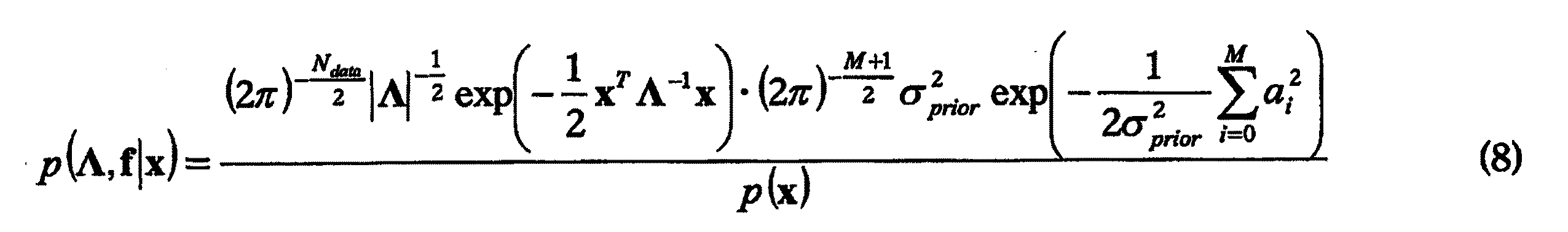
最尤推定の問題点は、事前の知識を正確に適用することが非常に難しいことである。これを克服するために、最大事後確率(MAP)推定が使用される。MAP推定では、全てのサンプルの事後分布が、
上記公式の自然対数を取り、全ての定係数を新しいものにグループ化すると、次の費用関数
実現および性能上の考慮事項。画像品質を最適化するために、全ての計算に32ビット浮動小数点演算を使用した。現在の×86プロセッサは、非常に効率的な並行処理を可能にする適正なSIMD(単一命令多重データ)コマンドを提供する。 Implementation and performance considerations. To optimize image quality, 32-bit floating point arithmetic was used for all calculations. Current x86 processors provide the proper SIMD (single instruction multiple data) commands that allow very efficient parallel processing.
補正プロトコル用の適切なタイムスタンプ較正画像フレーム。生成されるデータの量が巨大であり、かつ特定の状況では処理時間およびメモリ割当てが莫大であるため、実務上の理由から、データ収集サイクルCtの全てのタイプスタンプを用いることはできない。これは、現在の大面積カメラが最高で508×512画素の画像を提供するためである。1画素当たり最高で4つのパラメータがあり(三次多項式が用いられる場合)、各パラメータは4バイトである。これは、1フレーム当たり3.97MBのデータが収集されることを意味する。本実施形態では、カメラは毎秒50フレームを提供した。それは198MB/秒のデータ収集レートを意味する。これに加えて、画像は16ビットフォーマットでPCIバス全体に読み出され(24.8MB/秒)、メモリに格納された(別の24.8MB/秒)。したがって、50fpsの動作の場合の総合データレートは248MB/秒であった。フレーム平均モードでは、以前の画像値もメモリから読み出され、それは別の24.8MB/秒をもたらし、合計すると273MB/秒のメモリ帯域幅となる。画像がスクリーンに表示される場合、16ビット画素値がメモリから読み出され、32ビットのカラー値が画素毎に検索テーブルから読み出され、最終的32ビット値がディスプレイメモリに格納され、さらなる124MB/秒が加わり、合計すると397MB/秒となる。さらに、当該分野はもっと大きいカメラに移行しつつある。 An appropriate timestamp calibration image frame for the correction protocol. Due to the huge amount of data generated and in certain circumstances the processing time and memory allocation is enormous, for practical reasons, not all type stamps of the data collection cycle Ct can be used. This is because current large area cameras provide images of up to 508 × 512 pixels. There are a maximum of 4 parameters per pixel (when a cubic polynomial is used), and each parameter is 4 bytes. This means that 3.97 MB of data is collected per frame. In this embodiment, the camera provided 50 frames per second. That means a data collection rate of 198 MB / sec. In addition to this, the image was read across the PCI bus in 16-bit format (24.8 MB / sec) and stored in memory (another 24.8 MB / sec). Therefore, the total data rate in the case of 50 fps operation was 248 MB / sec. In frame average mode, the previous image value is also read from memory, which yields another 24.8 MB / sec, which totals a memory bandwidth of 273 MB / sec. When the image is displayed on the screen, 16-bit pixel values are read from memory, 32-bit color values are read from the lookup table for each pixel, and the final 32-bit value is stored in display memory for an additional 124 MB. / Second is added, for a total of 397 MB / second. In addition, the field is moving to larger cameras.
一次モデルを使用する場合、1つの画素は少なくとも2つの32ビット浮動小数点数/フレームを必要とする。30秒のデータ収集サイクル時間の場合、300fpsのフレームレートで96000画素の画像フレームは、単一データ収集サイクルで6.4GBのデータが生成されることを意味する。図12Aないし12Cはこれのさらなる例証である。図14aは、300fps、30秒サイクル、100000画素、4つのパラメータ、4バイト/パラメータの均一サンプリングとして知られる誤差サンプリングの先行技術の方法を示す。ここで我々は信号に対しては3次多項式、時間に対しては0次多項式を有する。しかし、300fps、30秒のデータ収集サイクル、および100000画素のカメラ、ならびに4バイト/パラメータで4つのパラメータの場合、13GBのデータを収集し、かつ処理しなければならない。これは非現実的である。図14bは、図14aと同様のカメラ動作パラメータ下で、収集しかつ処理すべきデータを約480MBしか生成しなかった、0次補間、300のデータセット、4つのパラメータでの誤差サンプリングの本発明の不均一な方法を示す。これにより、格納および処理要件は先行技術に比べて30分の1に減少する。サイクルの始めと終わりにアーチファクトがあることに注目されたい。図14cは、10のデータセット、4つのパラメータの場合に線形補間を使用する好適な不均一誤差サンプリング方法を示す。図14aと同様のカメラ動作パラメータ下で、この方法は、収集しかつ処理すべきデータを約16MB生成しただけであった。これにより、格納および処理要件は図14aの先行技術の方法に比べて30分の1に減少する。サイクルの始めと終わりに小さいアーチファクトがあることに注目されたい。双線形補正は、信号に対し線形かつ時間に対し線形であった。時間の線形補間は見かけの信号の非線形性を低減し、したがって信号の信号補正は適正である。 When using the primary model, one pixel requires at least two 32-bit floating point numbers / frame. For a 30 second data acquisition cycle time, an image frame of 96000 pixels at a frame rate of 300 fps means that 6.4 GB of data is generated in a single data acquisition cycle. Figures 12A-12C are a further illustration of this. FIG. 14a shows a prior art method of error sampling known as 300 fps, 30 second cycle, 100000 pixels, 4 parameters, 4 bytes / parameter uniform sampling. Here we have a third order polynomial for the signal and a 0th order polynomial for the time. However, for 300 fps, a 30 second data collection cycle, and a 100,000 pixel camera, and 4 parameters at 4 bytes / parameter, 13 GB of data must be collected and processed. This is unrealistic. FIG. 14b shows the present invention of zero-order interpolation, 300 data sets, error sampling with four parameters, which produced only about 480 MB of data to be collected and processed under the same camera operating parameters as FIG. 14a. This shows a non-uniform method. This reduces storage and processing requirements by a factor of 30 compared to the prior art. Note that there are artifacts at the beginning and end of the cycle. FIG. 14c shows a preferred non-uniform error sampling method using linear interpolation for 10 data sets, 4 parameters. Under the same camera operating parameters as in FIG. 14a, this method only generated about 16 MB of data to collect and process. This reduces storage and processing requirements by a factor of 30 compared to the prior art method of FIG. 14a. Note the small artifacts at the beginning and end of the cycle. Bilinear correction was linear with respect to the signal and linear with respect to time. Linear interpolation of time reduces the non-linearity of the apparent signal, so signal correction of the signal is correct.
図7および14cに示す通り、最適化された部分集合画像フレームを利用することを選択することができ、それに本発明の較正が行なわれる。データ収集サイクルCtの始めにおける画素セルの時間40にわたる回路出力信号の変化はより劇的である。この大きい変動性のため、較正データセットは、収集サイクルCtのこの部分からの基準フレームを、時間40にわたる出力信号が比較的平坦になり得る収集サイクルCtの終わり付近より、比較的多く含む必要がある。好適な実施形態では、自動的方法を使用して、ユーザが照射時間(つまりフレームレート)および/または検出器バイアス電圧50のオフ時間を変更できるようにしたが、設定は手動的に達成することもできる。図示したグラフでは、1つの棒が1組の較正値を表わすことに注目されたい。
As shown in FIGS. 7 and 14c, one can choose to utilize an optimized subset image frame, which is subjected to the calibration of the present invention. The change in the circuit output signal over
どの画素をマスキングするかの選択方法。撮像装置28の画素セル29の一部は、材料および製造上の欠陥のため、事実上役に立たない。したがって、これらの画素セル29を特定し、マスキングしなければならない。つまり、これらの出力の各々は、隣接する画素セル29から算出された何らかの合理的な値と置換される。本発明の較正方法は、1組の隣接する画素セル出力の局所的平均値を算出し、次いでこの値を個別画素出力信号値と比較する。これにより、該較正方法を非静止放射線分野に適応させることができる。好適な実施形態により、単一の基準放射線照射野強度設定で少なくとも5つの完全なデータ収集サイクルでの平均フレームを算出した。これにより、最小限の時間で撮像装置28における不良画素セル29の非常に頑健で信頼できる決定が達成された。
How to select which pixels are masked. Some of the
置換値の算出。全ての不良画素セル29が特定された後、それらの値はそれらの局所的算術平均値に置換される。したがって、単独の不良画素セル29の出力信号は、4つの適正な隣接画素出力信号の平均値に置換される。不良画素セル29からの画素出力信号は、この計算で除外される。全ての可能な方向が同等に加重されるように、4つの適正な隣接画素セル29を選択した。例えば第1不良画素セル29の上の画素セル29も不良である場合には、代わりに左上または右上いずれかの画素セル29が、第1不良画素セル29の画素出力信号の置換値の計算に使用される。
Calculation of replacement values. After all
幾何形状補正および非アクティブゾーンの充填。ASICハイブリッド上の相対的位置は理想的には近接し、かつ均等である。それは、隣接するハイブリッド間に多少の非アクティブ領域不活性領域(デッドスペース)があること、および異なる隣接ハイブリッド間の相対的距離が変動し得ることを意味する。この問題の解決策は2段階である。最初にハイブリッド間の距離、および基準物体の較正画像に基づくハイブリッドの可能な回転角について測定した。次いで、これらの測定に基づいて誤差を補正した。カメラ自体を測定装置として使用し、非常に正確な寸法を有する較正済み基準物体の画像を撮影することによって、測定を行なった。次いで、距離を測定した後、既知の値と測定値とを比較し、不一致を検出した。 Geometric correction and inactive zone filling. The relative positions on the ASIC hybrid are ideally close and even. That means that there is some inactive area inactive area (dead space) between adjacent hybrids and the relative distance between different adjacent hybrids can vary. The solution to this problem is in two stages. First, the distance between the hybrids and the possible rotation angle of the hybrids based on the calibration image of the reference object were measured. The error was then corrected based on these measurements. Measurements were made by taking an image of a calibrated reference object with very accurate dimensions, using the camera itself as a measuring device. Then, after measuring the distance, the known value was compared with the measured value, and a mismatch was detected.
不一致の補正および充填。ハイブリッドの正確な測位の後、補正アルゴリズムを実現した。距離に基づいて、所定の画素が画像内でどこに位置するべきかを厳格に示すグリッドを構築した。これに基づいて、双線形補間(または他のいずれかの補間方法)方法を使用して、サブ画素を平行移動しかつ回転した新しい画素値を得た。 Inconsistency correction and filling. After the accurate positioning of the hybrid, the correction algorithm was realized. Based on the distance, a grid was constructed that shows exactly where a given pixel should be located in the image. Based on this, bilinear interpolation (or any other interpolation method) method was used to obtain new pixel values that were translated and rotated subpixels.
本明細書に記載した発明の実施形態に、多数の変形および修正が可能である。本発明の特定の例示的実施形態についてここで図示しかつ説明したが、上記の開示に広範囲の修正、変形、および置換が考えられる。場合によっては、本発明の一部の特徴を、他の特徴を相応して使用することなく、使用することができる。したがって、上記の説明は広義に解釈し、単なる解説および実施例として掲げたものと理解することが適切であり、本発明の精神および範囲は添付する特許請求の範囲によってのみ限定される。 Numerous variations and modifications can be made to the embodiments of the invention described herein. Although particular exemplary embodiments of the present invention have been illustrated and described herein, a wide range of modifications, variations, and substitutions are possible in the above disclosure. In some cases, some features of the present invention can be used without correspondingly using other features. Accordingly, it is appropriate that the above description be interpreted broadly and understood as merely illustrative and exemplary, and the spirit and scope of the present invention be limited only by the appended claims.
Claims (47)
各フレームは未補正画像画素値の配列(45)を含み、装置が
a.異なる画像フレームからの前記画像画素値を補正するための手段(20、49、22、24)と、
b.複数のフレームからの補正画素値を利用し、画像の補正画素値を算出するための処理手段(24)と、
を備えることを特徴とする装置(28)。 An X-ray imaging device (28) capable of generating a plurality of image frames (44) suitable for displaying an image in real time,
Each frame includes an array (45) of uncorrected image pixel values, and the device includes a. Means (20, 49, 22, 24) for correcting the image pixel values from different image frames;
b. Processing means (24) for calculating corrected pixel values of an image using corrected pixel values from a plurality of frames;
A device (28) comprising:
前記検出基板は、衝突高エネルギーX線ガンマ線放射(80)を電荷に直接変換すること、および前記電荷を前記画素(36)間の電気接続(35)を介して前記ASIC読出し基板(32)上の対応する画素回路に電荷信号として伝達することを提供し、
前記画素回路は、各画素から電荷信号を処理することを提供する、
請求項1に記載の装置(28)。 High energy with high pixel density direct conversion radiation detector substrate (30) and detector substrate pixels (36) electrically connected to corresponding pixel circuits (31) on the ASIC readout substrate (32) An X-ray imaging camera (37);
The detection substrate directly converts impinging high energy X-ray gamma radiation (80) into charge, and the charge on the ASIC readout substrate (32) via an electrical connection (35) between the pixels (36). Providing a charge signal to a corresponding pixel circuit of
The pixel circuit provides for processing a charge signal from each pixel;
Apparatus (28) according to claim 1.
前記正規化モジュールが前記高速フレームプロセッサモジュールから実時間画像フレームデータ/レコードを受け取り、前記検索テーブルから画素特異的補正データを受け取り、ディスプレイモジュール(14)用のディスプレイ画像出力を介して正規化画像データを提供して、高エネルギーの直接検出X線撮像システム(10)のX線画像を提示する、請求項5に記載の装置(28)。 The normalization module (24) is in selective communication with the fast frame processor module (18) and the lookup table (22);
The normalization module receives real time image frame data / records from the high speed frame processor module, receives pixel specific correction data from the lookup table, and normalizes image data via a display image output for a display module (14). The apparatus (28) of claim 5, wherein the apparatus (28) provides an x-ray image of a high energy direct detection x-ray imaging system (10).
前記検出基板は、衝突高エネルギーX線ガンマ線放射(80)を電荷に直接変換すること、かつ前記電荷を前記画素(36)間の電気接続(35)を介して前記ASIC読出し基板(32)上の対応する画素回路に電荷信号として伝達することを提供し、
前記画素回路は、各画素からの電荷信号を処理することを提供する、
請求項21に記載の装置(28)。 High energy with high pixel density direct conversion radiation detector substrate (30) and detector substrate pixels (36) electrically connected to corresponding pixel circuits (31) on the ASIC readout substrate (32) An X-ray imaging camera (37);
The detection substrate directly converts impinging high energy X-ray gamma radiation (80) into charge, and the charge on the ASIC readout substrate (32) via an electrical connection (35) between the pixels (36). Providing a charge signal to a corresponding pixel circuit of
The pixel circuit provides for processing a charge signal from each pixel;
Device (28) according to claim 21.
Applications Claiming Priority (4)
| Application Number | Priority Date | Filing Date | Title |
|---|---|---|---|
| US60/585,742 | 2004-07-06 | ||
| US11/017,629 | 2004-12-20 | ||
| US11/017,629 US20060011853A1 (en) | 2004-07-06 | 2004-12-20 | High energy, real time capable, direct radiation conversion X-ray imaging system for Cd-Te and Cd-Zn-Te based cameras |
| PCT/IB2005/001896 WO2006003487A1 (en) | 2004-07-06 | 2005-07-01 | High energy, real time capable, direct radiation conversion x-ray imaging system for cd-te and cd-zn-te based cameras |
Publications (2)
| Publication Number | Publication Date |
|---|---|
| JP2008524874A true JP2008524874A (en) | 2008-07-10 |
| JP2008524874A6 JP2008524874A6 (en) | 2009-12-24 |
Family
ID=39661477
Family Applications (1)
| Application Number | Title | Priority Date | Filing Date |
|---|---|---|---|
| JP2007519900A Pending JP2008524874A (en) | 2004-12-20 | 2005-07-01 | High energy real-time capable direct radiation conversion X-ray imaging system for Cd-Te and Cd-Zn-Te based cameras |
Country Status (1)
| Country | Link |
|---|---|
| JP (1) | JP2008524874A (en) |
Cited By (7)
| Publication number | Priority date | Publication date | Assignee | Title |
|---|---|---|---|---|
| JP2009543603A (en) * | 2006-07-10 | 2009-12-10 | コーニンクレッカ フィリップス エレクトロニクス エヌ ヴィ | Energy spectrum reconstruction |
| WO2010125609A1 (en) * | 2009-04-30 | 2010-11-04 | 株式会社島津製作所 | Light or radiation imaging device |
| CN111226140A (en) * | 2017-10-19 | 2020-06-02 | 克罗梅克集团公开有限责任公司 | Modular Gamma Imaging Device |
| CN115273748A (en) * | 2022-09-01 | 2022-11-01 | 维沃移动通信有限公司 | Display module, display system, display driver, display method and electronic equipment |
| CN115755155A (en) * | 2022-11-04 | 2023-03-07 | 成都善思微科技有限公司 | Detector image quality monitoring method and system |
| US12033324B2 (en) | 2019-06-06 | 2024-07-09 | The Research Foundation For The State University Of New York | System and method for identifying fractures in digitized x-rays |
| US12379509B2 (en) | 2022-04-22 | 2025-08-05 | Canon Kabushiki Kaisha | Radiation detector, radiation imaging system, radiation image processing method, and storage medium |
Citations (6)
| Publication number | Priority date | Publication date | Assignee | Title |
|---|---|---|---|---|
| JPH0772252A (en) * | 1993-09-01 | 1995-03-17 | Fuji Photo Film Co Ltd | Image-signal reading method |
| JPH1098651A (en) * | 1996-09-25 | 1998-04-14 | Toshiba Corp | Solid-state imaging device |
| JPH11307756A (en) * | 1998-02-20 | 1999-11-05 | Canon Inc | Photoelectric conversion device and radiation reader |
| WO2003008999A2 (en) * | 2001-07-18 | 2003-01-30 | Koninklijke Philips Electronics Nv | Solid state x-radiation detector modules and mosaics thereof, and an imaging method and apparatus employing the same |
| JP2003066149A (en) * | 2000-08-14 | 2003-03-05 | Toshiba Corp | Radiation detector, radiation detection system, X-ray CT device |
| JP2003156565A (en) * | 2001-11-20 | 2003-05-30 | Canon Inc | Photographing device using photoelectric conversion device |
-
2005
- 2005-07-01 JP JP2007519900A patent/JP2008524874A/en active Pending
Patent Citations (6)
| Publication number | Priority date | Publication date | Assignee | Title |
|---|---|---|---|---|
| JPH0772252A (en) * | 1993-09-01 | 1995-03-17 | Fuji Photo Film Co Ltd | Image-signal reading method |
| JPH1098651A (en) * | 1996-09-25 | 1998-04-14 | Toshiba Corp | Solid-state imaging device |
| JPH11307756A (en) * | 1998-02-20 | 1999-11-05 | Canon Inc | Photoelectric conversion device and radiation reader |
| JP2003066149A (en) * | 2000-08-14 | 2003-03-05 | Toshiba Corp | Radiation detector, radiation detection system, X-ray CT device |
| WO2003008999A2 (en) * | 2001-07-18 | 2003-01-30 | Koninklijke Philips Electronics Nv | Solid state x-radiation detector modules and mosaics thereof, and an imaging method and apparatus employing the same |
| JP2003156565A (en) * | 2001-11-20 | 2003-05-30 | Canon Inc | Photographing device using photoelectric conversion device |
Cited By (9)
| Publication number | Priority date | Publication date | Assignee | Title |
|---|---|---|---|---|
| JP2009543603A (en) * | 2006-07-10 | 2009-12-10 | コーニンクレッカ フィリップス エレクトロニクス エヌ ヴィ | Energy spectrum reconstruction |
| WO2010125609A1 (en) * | 2009-04-30 | 2010-11-04 | 株式会社島津製作所 | Light or radiation imaging device |
| CN111226140A (en) * | 2017-10-19 | 2020-06-02 | 克罗梅克集团公开有限责任公司 | Modular Gamma Imaging Device |
| CN111226140B (en) * | 2017-10-19 | 2024-04-12 | 克罗梅克集团公开有限责任公司 | Modularized gamma imaging equipment |
| US12033324B2 (en) | 2019-06-06 | 2024-07-09 | The Research Foundation For The State University Of New York | System and method for identifying fractures in digitized x-rays |
| US12379509B2 (en) | 2022-04-22 | 2025-08-05 | Canon Kabushiki Kaisha | Radiation detector, radiation imaging system, radiation image processing method, and storage medium |
| CN115273748A (en) * | 2022-09-01 | 2022-11-01 | 维沃移动通信有限公司 | Display module, display system, display driver, display method and electronic equipment |
| CN115755155A (en) * | 2022-11-04 | 2023-03-07 | 成都善思微科技有限公司 | Detector image quality monitoring method and system |
| CN115755155B (en) * | 2022-11-04 | 2024-06-11 | 成都善思微科技有限公司 | Method and system for monitoring image quality of detector |
Similar Documents
| Publication | Publication Date | Title |
|---|---|---|
| US8530850B2 (en) | High energy, real time capable, direct radiation conversion X-ray imaging system for Cd-Te and Cd-Zn-Te based cameras | |
| US7355183B2 (en) | Imaging device | |
| US8072514B2 (en) | Imaging system and method for error reduction processing | |
| JP5317388B2 (en) | Radiation imaging apparatus, radiation imaging system, and program | |
| CN104285164A (en) | Digital X-ray Sensor | |
| US7512214B2 (en) | Radiography apparatus, radiography system, and control method thereof | |
| KR101999266B1 (en) | X-ray image apparatus and control method for the same | |
| CN103946692B (en) | The multiple repairing weld cmos sensor with the correction being for non-ideal sensor row for X-ray diffraction measurement | |
| CN112088320B (en) | Photon counting spectral CT | |
| US8547464B2 (en) | Solid-state imaging device and frame data correcting method which determine a voltage value corresponding to a pixel portion in frame data | |
| JP2008524874A (en) | High energy real-time capable direct radiation conversion X-ray imaging system for Cd-Te and Cd-Zn-Te based cameras | |
| JP2008524874A6 (en) | High energy real-time capable direct radiation conversion X-ray imaging system for Cd-Te and Cd-Zn-Te based cameras | |
| EP1617372B1 (en) | Imaging apparatus, control method thereof, and program | |
| US20050151086A1 (en) | Imaging device | |
| EP1795918B1 (en) | High energy, real time capable, direct radiation conversion x-ray imaging system for CD-TE and CD-ZN-TE based cameras | |
| JP5124332B2 (en) | Radiation inspection apparatus and calibration method | |
| US7415097B2 (en) | Method for recording correction frames for high energy images | |
| US8294793B2 (en) | Solid-state imaging device and frame data correcting method | |
| JP2004020300A (en) | Radiation diagnostic equipment | |
| Spartiotis et al. | X-and gamma ray imaging systems based on CdTe-CMOS detector technology |
Legal Events
| Date | Code | Title | Description |
|---|---|---|---|
| A521 | Request for written amendment filed |
Free format text: JAPANESE INTERMEDIATE CODE: A523 Effective date: 20080507 |
|
| A621 | Written request for application examination |
Free format text: JAPANESE INTERMEDIATE CODE: A621 Effective date: 20080507 |
|
| A521 | Request for written amendment filed |
Free format text: JAPANESE INTERMEDIATE CODE: A821 Effective date: 20100325 |
|
| RD02 | Notification of acceptance of power of attorney |
Free format text: JAPANESE INTERMEDIATE CODE: A7422 Effective date: 20100325 |
|
| RD04 | Notification of resignation of power of attorney |
Free format text: JAPANESE INTERMEDIATE CODE: A7424 Effective date: 20100407 |
|
| A521 | Request for written amendment filed |
Free format text: JAPANESE INTERMEDIATE CODE: A821 Effective date: 20100325 |
|
| A131 | Notification of reasons for refusal |
Free format text: JAPANESE INTERMEDIATE CODE: A131 Effective date: 20100629 |
|
| A601 | Written request for extension of time |
Free format text: JAPANESE INTERMEDIATE CODE: A601 Effective date: 20100908 |
|
| A602 | Written permission of extension of time |
Free format text: JAPANESE INTERMEDIATE CODE: A602 Effective date: 20100916 |
|
| A02 | Decision of refusal |
Free format text: JAPANESE INTERMEDIATE CODE: A02 Effective date: 20110301 |