JP2008522817A - Material processing equipment and its application - Google Patents
Material processing equipment and its application Download PDFInfo
- Publication number
- JP2008522817A JP2008522817A JP2007545819A JP2007545819A JP2008522817A JP 2008522817 A JP2008522817 A JP 2008522817A JP 2007545819 A JP2007545819 A JP 2007545819A JP 2007545819 A JP2007545819 A JP 2007545819A JP 2008522817 A JP2008522817 A JP 2008522817A
- Authority
- JP
- Japan
- Prior art keywords
- reaction
- group
- processing apparatus
- liquid
- material processing
- Prior art date
- Legal status (The legal status is an assumption and is not a legal conclusion. Google has not performed a legal analysis and makes no representation as to the accuracy of the status listed.)
- Pending
Links
Images


Classifications
-
- B—PERFORMING OPERATIONS; TRANSPORTING
- B01—PHYSICAL OR CHEMICAL PROCESSES OR APPARATUS IN GENERAL
- B01F—MIXING, e.g. DISSOLVING, EMULSIFYING OR DISPERSING
- B01F27/00—Mixers with rotary stirring devices in fixed receptacles; Kneaders
- B01F27/27—Mixers with stator-rotor systems, e.g. with intermeshing teeth or cylinders or having orifices
- B01F27/272—Mixers with stator-rotor systems, e.g. with intermeshing teeth or cylinders or having orifices with means for moving the materials to be mixed axially between the surfaces of the rotor and the stator, e.g. the stator rotor system formed by conical or cylindrical surfaces
-
- B—PERFORMING OPERATIONS; TRANSPORTING
- B29—WORKING OF PLASTICS; WORKING OF SUBSTANCES IN A PLASTIC STATE IN GENERAL
- B29B—PREPARATION OR PRETREATMENT OF THE MATERIAL TO BE SHAPED; MAKING GRANULES OR PREFORMS; RECOVERY OF PLASTICS OR OTHER CONSTITUENTS OF WASTE MATERIAL CONTAINING PLASTICS
- B29B7/00—Mixing; Kneading
- B29B7/30—Mixing; Kneading continuous, with mechanical mixing or kneading devices
- B29B7/34—Mixing; Kneading continuous, with mechanical mixing or kneading devices with movable mixing or kneading devices
- B29B7/38—Mixing; Kneading continuous, with mechanical mixing or kneading devices with movable mixing or kneading devices rotary
- B29B7/40—Mixing; Kneading continuous, with mechanical mixing or kneading devices with movable mixing or kneading devices rotary with single shaft
- B29B7/405—Mixing heads
- B29B7/407—Mixing heads with a casing closely surrounding the rotor, e.g. with conical rotor
-
- B—PERFORMING OPERATIONS; TRANSPORTING
- B01—PHYSICAL OR CHEMICAL PROCESSES OR APPARATUS IN GENERAL
- B01F—MIXING, e.g. DISSOLVING, EMULSIFYING OR DISPERSING
- B01F23/00—Mixing according to the phases to be mixed, e.g. dispersing or emulsifying
- B01F23/40—Mixing liquids with liquids; Emulsifying
- B01F23/41—Emulsifying
-
- B—PERFORMING OPERATIONS; TRANSPORTING
- B01—PHYSICAL OR CHEMICAL PROCESSES OR APPARATUS IN GENERAL
- B01F—MIXING, e.g. DISSOLVING, EMULSIFYING OR DISPERSING
- B01F27/00—Mixers with rotary stirring devices in fixed receptacles; Kneaders
- B01F27/27—Mixers with stator-rotor systems, e.g. with intermeshing teeth or cylinders or having orifices
- B01F27/272—Mixers with stator-rotor systems, e.g. with intermeshing teeth or cylinders or having orifices with means for moving the materials to be mixed axially between the surfaces of the rotor and the stator, e.g. the stator rotor system formed by conical or cylindrical surfaces
- B01F27/2722—Mixers with stator-rotor systems, e.g. with intermeshing teeth or cylinders or having orifices with means for moving the materials to be mixed axially between the surfaces of the rotor and the stator, e.g. the stator rotor system formed by conical or cylindrical surfaces provided with ribs, ridges or grooves on one surface
Landscapes
- Chemical & Material Sciences (AREA)
- Chemical Kinetics & Catalysis (AREA)
- Engineering & Computer Science (AREA)
- Mechanical Engineering (AREA)
- Physical Or Chemical Processes And Apparatus (AREA)
- Physical Water Treatments (AREA)
- Extraction Or Liquid Replacement (AREA)
- Colloid Chemistry (AREA)
- Mixers Of The Rotary Stirring Type (AREA)
Abstract
本発明では、材料を処理するのに用いることができる材料処理装置が開示される。本発明の材料処理装置は、円筒形状の処理部および駆動部を有して成る。処理部は、第1要素、および第1要素内に配置された第2要素を有して成る。第1要素と第2要素との間の隙間には、処理すべき材料が含まれる収容チャンバーが形成されている。駆動部によって第2要素が駆動されることによって、第2要素が第1要素に対して相対的に回転する。第2要素の収容チャンバー側の面は、第1要素の軸に対して平行な方向の力を生じさせることが可能な分散部が設けられている。かかる第2要素に起因して、本発明の装置では、収容チャンバーにおける材料保持時間を制御することができ、混合されないブラインド領域へと材料が供されるのを防止できるので、全ての材料を十分に処理することができる。The present invention discloses a material processing apparatus that can be used to process materials. The material processing apparatus of the present invention includes a cylindrical processing unit and a driving unit. The processing unit includes a first element and a second element arranged in the first element. In the gap between the first element and the second element, an accommodation chamber containing a material to be processed is formed. When the second element is driven by the drive unit, the second element rotates relative to the first element. The surface of the second element on the side of the accommodation chamber is provided with a dispersion part capable of generating a force in a direction parallel to the axis of the first element. Due to this second element, the device of the present invention can control the material retention time in the containment chamber and prevent the material from being provided to the unblinded blind area, so that all the material is sufficient Can be processed.
Description
本発明は、材料を処理するための装置およびその応用に関する。 The present invention relates to an apparatus for processing materials and its applications.
食品産業および化学産業にとって、あるいは、抽出技術等にとって、材料の混合プロセスは非常に重要な工程である。混合プロセスによって、例えば以下のようなことが可能となる:
可溶性固形分、液体または気体を溶媒内に十分に混合させることができるので、均一な溶液を得ることができる。
不溶性固形粒子、気体または液体を一時的に溶媒内に分散させることができるので、懸濁液を得ることができる。
僅かに可溶性を有する液体を液滴として溶媒内に分散させることができるのでエマルションを得ることができる。
十分な混合により、反応原系同士の対流現象が促進されるので局所的な濃度差を減じることができる。
溶液内で対流を促進させて局所的な温度差を減じることができるので、熱放出を均一にすることができ、温度を一定に維持することができる。
現在、混合プロセスにおいて使用される方法が数多く存在している。
The material mixing process is a very important step for the food and chemical industries or for the extraction technology. The mixing process allows, for example:
Since the soluble solid, liquid or gas can be sufficiently mixed in the solvent, a uniform solution can be obtained.
Since insoluble solid particles, gas or liquid can be temporarily dispersed in the solvent, a suspension can be obtained.
Since a slightly soluble liquid can be dispersed in the solvent as droplets, an emulsion can be obtained.
By sufficient mixing, the convection phenomenon between the reaction source systems is promoted, so that the local concentration difference can be reduced.
Since convection can be promoted in the solution to reduce the local temperature difference, the heat release can be made uniform and the temperature can be kept constant.
There are currently many methods used in the mixing process.
最も直接的な混合は、容器内で材料を高速に攪拌する方法である。数多くの攪拌機(またはスターラー)が市販されている。最も一般的な攪拌法は、ある程度の長い時間、容器内に設けられた1つ以上の攪拌棒を迅速に作動させて液体を混合する方法である。例えば、長く攪拌を行うと、油と水との混合物は、適当なエマルション状態の液体となる。 The most direct mixing is a method of stirring the material at high speed in a container. Many stirrers (or stirrers) are commercially available. The most common stirring method is a method in which liquid is mixed by rapidly operating one or more stirring rods provided in a container for a certain long time. For example, if stirring is performed for a long time, the mixture of oil and water becomes a liquid in an appropriate emulsion state.
攪拌棒に対して十分なスペース(または空間)を確保するためには、容量の大きい容器が必要とされる。しかしながら、そのような大きい容器は、マイクロスケールで液体を混合するのに適していないだけでなく、気体と液体との混合にも適していない。更に、混合物が飛び散る(又ははじき飛ばされる)のでミキサーの速度(または攪拌速度)は制限されており、あまり速い速度にすることができない。複数の混合プロセスの自動化および効率化の程度は、各々の混合工程の後に洗浄が必要となるので低いといえる。また、混合に際してガスが発生する場合では、発生したガスを大きな容器で回収するのは好都合ではない。また、反応プロセスにおいて混合物の加熱または冷却が必要な場合では、かかる大きな容器内を均一に加熱または冷却するのは容易ではなく、反応が不均一となってしまう。それゆえ、容器内での材料混合に攪拌棒を使用する方法は、混合率が良いとはいえない。 In order to ensure a sufficient space (or space) for the stirring bar, a container having a large capacity is required. However, such large containers are not only suitable for mixing liquids on a microscale, but also not suitable for mixing gases and liquids. Furthermore, the speed of the mixer (or stirring speed) is limited because the mixture splatters (or is repelled) and cannot be made too fast. The degree of automation and efficiency of the plurality of mixing processes can be said to be low because cleaning is required after each mixing step. In addition, when gas is generated during mixing, it is not convenient to collect the generated gas in a large container. Further, when heating or cooling of the mixture is required in the reaction process, it is not easy to uniformly heat or cool the inside of such a large container, and the reaction becomes non-uniform. Therefore, it cannot be said that the method of using a stirring bar for mixing the materials in the container has a good mixing rate.
別の方法としては、ステーター(stator)と同軸になるようにステーターの円筒形状ホール内に配置された円筒形ローターを用いる方法がある。ステーターとローターとの2つの対向する円筒形面によって、狭い環状チャンバーが形成される。流体を環状チャンバー内に注入した後、ローターを高速に回転させると、スターターとローターとの相対的な運動によって流体に大きな剪断力がもたらされるので混合を行うことができる。回転速度が或る値に達すると、ローターの遠心力によって流体内にクエット流(Coutte)が形成される。クエット流が生じると混合効率が非常に高くなる(特に種々の非混和性流体に対する混合率が高い)。なぜなら、クエット流によって、非混和性流体が小さい粒状体へと分散されるので、流体間の接触面積が増大するからである。 Another method is to use a cylindrical rotor placed in a cylindrical hole in the stator so as to be coaxial with the stator. A narrow annular chamber is formed by two opposing cylindrical surfaces of the stator and the rotor. When the rotor is rotated at a high speed after the fluid is injected into the annular chamber, the relative movement between the starter and the rotor brings about a large shearing force on the fluid, so that mixing can be performed. When the rotational speed reaches a certain value, a Couette flow (Coutte) is formed in the fluid by the centrifugal force of the rotor. When the Couette flow occurs, the mixing efficiency becomes very high (particularly, the mixing ratio for various immiscible fluids is high). This is because the immiscible fluid is dispersed into small particles by the Couette flow, so that the contact area between the fluids increases.
しかしながら、ローター面の回転速度が或る程度大きくなると、環状チャンバー内の流体が不安定化してテイラー渦(またはテイラー渦流)が発生することになる。個々のテイラー渦内では独立した微小な循環流れ(microcirculation)が形成され、その外側の他の渦の流体との物質交換は行われない。更に、各々の渦内の層の間における相対速度または全体的な速度は小さい。そのため、テイラー渦が発生すると混合効率が低くなる。テイラー渦は、ローターのシャフトの横断方向にて環状チャンバー内に挟まれるように存在するので、環状チャンバー内の流体の速度は低くなる。更に、テイラー渦は、多量のエネルギーを消費するので、エネルギー節約の点から好ましいものではない。 However, when the rotational speed of the rotor surface increases to some extent, the fluid in the annular chamber becomes unstable and Taylor vortex (or Taylor vortex) is generated. Within each Taylor vortex, an independent microcirculation is formed, and no mass exchange with other vortex fluids outside it occurs. Furthermore, the relative velocity or overall velocity between the layers in each vortex is small. Therefore, when the Taylor vortex is generated, the mixing efficiency is lowered. Since the Taylor vortex exists so as to be sandwiched in the annular chamber in the transverse direction of the rotor shaft, the velocity of the fluid in the annular chamber is low. Furthermore, the Taylor vortex consumes a large amount of energy and is not preferable from the viewpoint of energy saving.
上述のような問題を解決するために、環状チャンバーのサイズ、面特性およびローターの回転速度を相互に適当に調整してテイラー渦の発生を回避すると共にクエット流を発生させて流体の混合を行う方法が存在している。かかる方法は、米国特許第6471392号および同6742774号にそれぞれ開示されている。米国特許第6471392号および同6742774号では、以下の2つのファクターによってテイラー渦の発生を回避している:
環状チャンバー厚さがローターおよびステーターの表面における流体層全体の厚さ以下となっている(即ち、ローターとステーターとの隙間が、テイラー渦を回避すべく十分に小さくなっている)。
ローターおよびステーターの円筒形状面が、テイラー渦の発生を阻止すべく円滑になっている。
In order to solve the above-described problems, the size of the annular chamber, the surface characteristics, and the rotational speed of the rotor are adjusted appropriately to avoid the generation of Taylor vortices and generate Couette flow to mix the fluid. There is a way. Such methods are disclosed in US Pat. Nos. 6,471,392 and 6,742,774, respectively. US Pat. Nos. 6,471,392 and 6,742,774 avoid the generation of Taylor vortices by the following two factors:
The annular chamber thickness is less than or equal to the total fluid layer thickness on the rotor and stator surfaces (ie, the gap between the rotor and stator is sufficiently small to avoid Taylor vortices).
The cylindrical surfaces of the rotor and stator are smooth to prevent Taylor vortex generation.
しかしながら、テイラー渦理論に基づくと、回転速度、環状チャンバーの半径および流体粘度から求められるテイラー係数の値が臨界値を越えてしまうと、環状チャンバーの隙間がどのような厚さ(または大きさ)であれ、テイラー渦が生じることになる。例えば、流体特性および環状チャンバー・サイズが一定の場合、回転速度が十分に大きいと、テイラー渦が発生する可能性がある。それゆえ、米国特許第6471392号および同6742774号に基づいて製造された環状チャンバーでは、或る限定された回転速度および流体粘度においてのみクエット流を発生できるにすぎない。つまり、回転速度が或る値を上回り、流体粘度が或る値を下回ると、テイラー渦が発生してしまう。 However, based on the Taylor vortex theory, if the value of the Taylor coefficient determined from the rotation speed, the radius of the annular chamber and the fluid viscosity exceeds a critical value, the thickness (or size) of the gap in the annular chamber Even so, a Taylor vortex will occur. For example, if the fluid properties and the annular chamber size are constant, Taylor vortices can occur if the rotational speed is high enough. Therefore, annular chambers manufactured according to US Pat. Nos. 6,471,392 and 6,742,774 can only generate Couette flow at certain limited rotational speeds and fluid viscosities. That is, if the rotational speed exceeds a certain value and the fluid viscosity falls below a certain value, a Taylor vortex is generated.
尚、流体粘度が臨界値未満の条件では、回転速度が臨界値を越えるような速度で環状チャンバーを運転しなければならず、テイラー渦の発生を回避することができない。つまり、「テイラー渦をもたらす回転速度の増加」と「混合効率」とが相反する結果となる。従って、既存の混合法の条件下では、「回転速度の増加」とテ「イラー渦発生回避」との間で妥協点を見つけなければならない。 Note that, under conditions where the fluid viscosity is less than the critical value, the annular chamber must be operated at a speed at which the rotational speed exceeds the critical value, and the generation of Taylor vortices cannot be avoided. That is, the “increase in the rotational speed that causes the Taylor vortex” and the “mixing efficiency” conflict with each other. Therefore, under the conditions of the existing mixing method, a compromise must be found between "increase in rotational speed" and tele "avoid vortex generation".
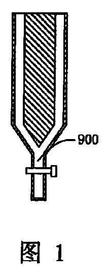
図1を参照して説明する。既存のローターが回転する場合、不完全な混合状態の流体が、重力の影響を受けて環状チャンバー底部の出口から流出することになり、混合率および反応率に悪影響がもたらされ得る。かかる流体の流出を防止するために、一般的には底部の出口にバルブを設ける。しかしながら、バルブと環状チャンバーとの間には、参照番号900で示すように「混合されないブラインド領域(または淀み領域,blind area)」が必然的に多少なりとも形成されてしまい、かかるブラインド領域では流体の十分な混合が行われないので無駄な流体が発生し、原料が無駄となってしまう。
A description will be given with reference to FIG. When the existing rotor rotates, the fluid with imperfect mixing will flow out of the outlet at the bottom of the annular chamber under the influence of gravity, which can adversely affect the mixing rate and reaction rate. In order to prevent the fluid from flowing out, a valve is generally provided at the bottom outlet. However, a “blind area” (or a stagnation area) is inevitably formed between the valve and the annular chamber, as indicated by
それゆえ、従来技術の上記問題点を解決できるような新規な材料処理装置の提供が望まれている。 Therefore, it is desired to provide a novel material processing apparatus that can solve the above-described problems of the prior art.
本発明は、材料を十分に処理することができる材料処理装置に関する。 The present invention relates to a material processing apparatus capable of sufficiently processing a material.
上述の目的を達成するため、本発明では、処理部(または「材料処理を行うように機能する部分」,working part)および駆動部を有して成る材料処理装置が提供される。かかる本発明の材料処理装置では、処理部が、第1要素、および第1要素内に配置された第2要素を有して成り、
第1要素と第2要素との間の隙間には、処理すべき材料が含まれる収容チャンバー(containing chamber)が形成されており、
駆動部によって第2要素が駆動されることによって、第2要素が第1要素に対して相対的に回転し、
第1要素または第2要素の収容チャンバー側の面(または表面)が非平滑(non-smooth)となっている。尚、材料の処理としては、混合、乳化、マイクロ乳化、重合、抽出、反応および調製ならびにそれらの組合せ等を挙げることができる。第2要素が第1要素に対して相対的に回転する際、第2要素の非平滑な面は第1要素に接触しないようになっている。
In order to achieve the above object, the present invention provides a material processing apparatus having a processing unit (or “working part that functions to perform material processing”) and a driving unit. In the material processing apparatus of the present invention, the processing unit includes a first element and a second element arranged in the first element,
In the gap between the first element and the second element, a containing chamber containing the material to be processed is formed,
When the second element is driven by the driving unit, the second element rotates relative to the first element,
The surface (or surface) of the first element or the second element on the accommodation chamber side is non-smooth. Examples of material processing include mixing, emulsification, microemulsification, polymerization, extraction, reaction and preparation, and combinations thereof. When the second element rotates relative to the first element, the non-smooth surface of the second element does not contact the first element.
ある態様では、第1要素および第2要素の双方の収容チャンバー側の面が非平滑となっている(又は滑らかになっていない)。 In a certain aspect, the surface of the accommodation chamber side of both the first element and the second element is non-smooth (or not smooth).
ある態様では、第1要素の収容チャンバー側の非平滑な面が、第1要素の軸に対して平行な方向に軸力(axial force)を生じさせることが可能な分散部(または分配部, distributing part)を有して成る。 In one embodiment, the non-smooth surface of the first element on the receiving chamber side can generate an axial force in a direction parallel to the axis of the first element (or distribution part, distributing part).
ある態様では、第2要素の収容チャンバー側の非平滑な面が、第1要素の軸に対して平行な方向に軸力を生じさせることが可能な分散部を有している。 In one aspect, the non-smooth surface of the second element on the accommodation chamber side has a dispersion portion that can generate an axial force in a direction parallel to the axis of the first element.
従来技術と比べて、本発明の材料処理装置の非平滑な面または第2要素の分散部は、テイラー渦を分散させる機能を有している。その結果、混合効率を上げることができ、また、収容チャンバー内の流体の保持時間(または滞留時間)を制御することができ、更には、液体が「ブラインド領域」へと流れ込むことを防止して流体の全てを十分に混合することができる。従って、本発明の装置では材料の十分な混合を行うことができ、収容チャンバー内の材料の保持時間を制御することができ、全ての材料の混合または反応等を十分に行うことができる。 Compared with the prior art, the non-smooth surface of the material processing apparatus of the present invention or the dispersion portion of the second element has a function of dispersing Taylor vortices. As a result, the mixing efficiency can be increased, the retention time (or residence time) of the fluid in the containing chamber can be controlled, and further, the liquid can be prevented from flowing into the “blind area”. All of the fluids can be mixed well. Therefore, in the apparatus of the present invention, the materials can be sufficiently mixed, the retention time of the materials in the storage chamber can be controlled, and all materials can be sufficiently mixed or reacted.
ある態様では、第1要素15が静止した(または固定された)ステーターであり、第2要素16が高速で回転可能なローターである。ある態様では、第1要素15および第2要素16が円筒形状を有している。この場合、第1要素15は、その軸方向に沿うように円筒形状ホール(cylindrical hole)を有しており、第2要素16が第1要素15と同軸となるように第1要素15の円筒形状ホール内に配置されている。
In one embodiment, the
ある態様では、第1要素と第2要素との隙間に形成される収容チャンバーの少なくとも1つの寸法は、ミクロンオーダー(μmオーダー)となっている。例えば、収容チャンバー17の厚さ(または幅)は、数十ミクロン〜数千ミクロンのミクロンオーダーとなっている。より具体的には、収容チャンバー17の厚さ(または幅)は、50〜80ミクロン、80〜120ミクロン(例えば100ミクロン)、120〜130ミクロン、130〜200ミクロン(例えば200ミクロン)、200〜350ミクロン、約350ミクロン、約1000ミクロン、約2000ミクロン、約3000ミクロンなどに設定されている。収容チャンバー17の厚さが非常に小さくなっていると共に、第2要素16の収容チャンバー側の面が非平滑となっているにもかかわらず、第2要素16が第1要素15に対して相対的に回転する際、第2要素16と第1要素15が相互に接触しないようになっている。
In one embodiment, at least one dimension of the storage chamber formed in the gap between the first element and the second element is on the order of microns (μm order). For example, the thickness (or width) of the
ある態様では、図3および図4に示すように、第2要素16の収容チャンバー17側の非平滑面が分散部160として構成されている。かかる分散部160は、微細加工、電食、フォトエッチング(もしくは写真食刻)などによって第2要素16の面に一体的に形成することができる。あるいは、電気メッキ、強力な接着剤などによって第2要素16の面に分散部160を取り付けることができる。分散部160は、その回転に際して第1要素の軸に対して平行な軸力を供することができるものであれば、いずれの形態であってもよい。しかしながら、分散部160がどのような形態であろうと、また、収容チャンバー17に対してどのように突出した形態を有していようとも、第2要素16が第1要素15に対して相対的に回転する際に第2要素16と第1要素15が相互に接触することはない。即ち、分散部160の配置がどのようなものであっても、分散部160は収容チャンバー17内に位置することになる。
In one embodiment, as shown in FIGS. 3 and 4, the non-smooth surface of the
ある態様では、分散部160は、第2要素16の面にて凸形状を有していてもよいし、凹形状を有していてもよい。ある態様では、分散部160の凸部または凹部は、収容チャンバー17の平均厚さの約1%〜300%である。例えば、収容チャンバーの厚さが100ミクロンに設定される場合、第2要素160の半径方向において最も突出している箇所と最も凹んでいる箇所と間の長さが、約1〜300ミクロンである。ある態様では、分散部160の凸部または凹部は、収容チャンバー17の平均厚さの約5%〜100%である。また、ある態様では、分散部160の凸部または凹部は、収容チャンバー17の平均厚さの約10%〜30%である。尚、第2要素の面における分散部160の凸部および/または凹部の程度は、同じであってもよいし、あるいは、異なっていてもよい。
In a certain aspect, the dispersion |
ある態様では、第2要素15に設けられている分散部160は、第2要素15の面の50%未満を占めている。好ましい態様では、分散部160が第2要素15の面の10%〜40%未満を占めている。
In a certain aspect, the
ある態様では、分散部160は、複数のドット(または点、dot)の配列、連続的なストライプ(もしくは連続的なストライプ模様もしくは連続的な縞模様、continuous stripes)または不連続なストライプ(もしくは不連続なストライプ模様、もしくは不連続な縞模様、discontinuous stripe)であり、あるいは、そのようなドットとストライプとの組合せである。ある態様では、分散部160は第2要素16の面に不規則に又は規則正しく設けられている。ある態様では、各ストライプの方向は、第2要素16の軸方向に対して垂直または平行でない限り、不規則であってよい。ある態様では、ストライプ状の分散部160が、第2要素16の底部から頂部まで連続的または不連続に設けられている。ある態様では、ストライプの間隔が、等間隔(equi-spaced)または非等間隔(unequi-spaced)となっており、ストライプが互いに交差していてもよい。ある態様では、特に制限するわけではないが、分散部160は図4に示すような連続的で等間隔なストライプを有して成る。
In some embodiments, the
ある態様では、分散部160の断面は、特に制限するわけではないが、三角形、台形、正方形、多角形、半円形、半楕円形またはそれらを組み合せたような形状を有している。図4には断面が三角形の分散部160が示されている。
In one embodiment, the cross section of the
ある態様では、図4に示すように、分散部160は連続的なストライプを成している。第2要素16が回転する際、分散部160の連続的ストライプと第2要素16の面の接平面とが交差するポイント(または交点)が連続的に流れることになる。かかる交点の流れ方向は、対応するストライプのトレンド方向(または傾斜方向、trend direction)である。分散部160のトレンド方向は、その一般的な回転方向が第2要素16の回転方向と反対または同じである限り、不規則となり得る。全て又は大部分のストライプが同じトレンド方向となる場合、流体に対してトレンド方向に沿う衝撃力(impulse force)が加えられる。かかる衝撃力は、第1要素15の軸に平行な方向の力を成し得るので、流体が第2要素16の回転シャフトまたは軸方向に沿って流れることになる。分散部のトレンド方向は、第2要素16の回転方向に相当する。第2要素が回転する際、分散部の回転方向とトレンド方向との関係に応じて、分散部160が入口31および/または32に向かう方向へと力を生じるので、収容チャンバー17内の流体の保持時間を長くすることができる。尚、分散部は出口に向かう方向にも力を生じることができるので、その場合には、収容チャンバー17内の流体の保持時間を短くできる。
In one embodiment, as shown in FIG. 4, the
ある態様では、図5および図6に示すように、第2要素16の断面は多角形または楕円形であってよい。この場合、第2要素が高速で回転すると、収容チャンバー17内の或る位置が回転に伴って変化することになる。従って、収容チャンバー17内の流体には不均一な力が加えられ、流体が十分に混合される。当然のことであるが、第2要素16の断面は、他の形状であってもよく、図5の楕円形または図6の多角形は例示にすぎない。
In certain aspects, as shown in FIGS. 5 and 6, the cross-section of the
ある態様では、図7に示すように、第2要素16の軸と第1要素15の軸とがずれていてもよい(または非同軸であってもよい)。この場合、収容チャンバー17内の流体には不均一な力が加えられ、流体が十分に混合される。
In one aspect, as shown in FIG. 7, the axis of the
ある態様では、第1要素と第2要素との位置関係を入れ替えてもよい。即ち、第2要素16が静止した(または固定された)ステーターであり、第1要素15が高速で回転できるローターであってよい。ある態様では、第1要素15と第2要素16とが相対的に反対方向に回転する回転要素であってもよい(この場合、回転速度は互いに異なっていてもよい)。第1要素15と第2要素16との間に流体のための収容チャンバー17が形成される限り、第1要素15および第2要素16はいずれの形状を有していてもよく、相互に接近した形態でもよい(例えば相互に接近したパッチなどの形状であってよい)。ある態様では、第1要素15および/または第2要素16に分散部が設けられ得る。
In an aspect, the positional relationship between the first element and the second element may be interchanged. That is, the
ある態様では、第1要素の内面(即ち、第1要素の収容チャンバー側の面)に第1分散部が設けられ、第2要素の外側(即ち、第2要素の収容チャンバー側の面)に第2分散部が設けられる。ある態様では、第1要素に設けられた第1分散部と、第2要素に設けられた第2分散部とが同じトレンド方向を成している。あるいは、第1要素に設けられた第1分散部は、第2要素に設けられた第2分散部とは逆または反対のトレンド方向を有している。 In one embodiment, the first dispersion portion is provided on the inner surface of the first element (that is, the surface of the first element on the accommodation chamber side), and on the outer side of the second element (that is, the surface of the second element on the accommodation chamber side). A second dispersion unit is provided. In a certain aspect, the 1st dispersion | distribution part provided in the 1st element and the 2nd dispersion | distribution part provided in the 2nd element have comprised the same trend direction. Or the 1st dispersion | distribution part provided in the 1st element has a trend direction contrary or opposite to the 2nd dispersion | distribution part provided in the 2nd element.
ある態様では、収容チャンバー17の頂部には、材料を収容チャンバー17内に供するための入口が2つ(30,31)設けられている一方、収容チャンバー17の底部には出口18が設けられている。必要に応じて、入口30,31および出口18は他の位置に設けてよい。尚、入口30,31および出口18は収容チャンバー17と連通状態となっている。入口30,31および出口18は、収容チャンバー17内に材料を供給した後、かかる収容チャンバー17から材料を排出できるものであれば、いずれの要素であってよく、例えばパイプまたはバルブである。ある態様では、入口30,31および出口18は、同じ要素もしくはデバイスであってよく、あるいは、相互に異なる要素もしくはデバイスであってもよい。
In one embodiment, the top of the
ある態様において、処理すべき材料が混合流体である場合、本発明の処理装置に設ける入口は1つであってよい。また、ある態様において、処理(混合および/または反応)すべき材料が複数である場合、本発明の処理装置に複数の入口を設けてもよい。更に、ある態様において、反応時に必要とされる材料を供するために、予め複数の入口を設けておいてもよい。 In one embodiment, when the material to be processed is a mixed fluid, the processing apparatus of the present invention may have one inlet. Moreover, in a certain aspect, when there are a plurality of materials to be processed (mixed and / or reacted), a plurality of inlets may be provided in the processing apparatus of the present invention. Further, in some embodiments, a plurality of inlets may be provided in advance in order to provide materials required during the reaction.
処理される材料は、入口30および31を介して環状収容チャンバー17内に供給される。そして、高剪断力、大きい遠心力および軸力などの作用を第2要素16から受けることになるので、供給された材料の迅速かつ均一な混合が達成される。材料同士が反応する場合、材料の十分な混合により十分な反応を達成することができる。
The material to be processed is fed into the
本発明の装置において、収容チャンバー17内の流体の流れ状態は、層流であっても、乱流であってもよい。第2要素16の高速回転によって生じる力によって、層流状態の流体は複数の流体薄層物(lamella)へと分けられることになる。環状収容チャンバーの半径方向では、流体薄層物の流速が相互に異なるので、流体薄層物が相互に迅速に緊密な状態となり、迅速に拡散する。これによって、流体の十分な混合が行われる。テイラー・クエット流の理論に基づくと、次のことが言える。あるサイズの処理部を製作した後に、かかる処理部に応じて収容チャンバー17のギャップ幅が決められる。ローターの種々の回転速度の条件下、種々の粘度の流体について、クエット流れが生じるか、あるいはテイラー渦が生じるかは、テイラー係数に依存している。ローターの回転が低速の場合、流体は収容チャンバー17内を層流状態で流れることになり、かかる条件では混合効率が比較的良いものの、低い回転速度に起因して、供給される流体の流速を大きくすることができない。仮に、供給される流体の流速を大きくすると、流体が収容チャンバー17内をその軸方向に迅速に流れ去ることになり、高い混合効率を得ることができない。好ましい混合効率および大きい流速の条件で流体を混合するには、ローターの回転速度を上げる必要があるが、ローターの回転速度を上げてしまうと、テイラー渦が生じてしまい混合効率が低下してしまう。本発明の処理装置では、上述したように、第2要素16に設けられた分散部160に起因した軸力が生じる。その結果、第2要素16の軸方向において、垂直方向に配列されたテイラー渦が乱さると共に、テイラー渦によって形成された「閉鎖形態の流体セル」が破壊されることになる。それゆえ、渦の内側と外側とで流体の物質交換が相互に交換されることになり、混合効率が向上する。また、分散部160によって、各渦内の独立したマイクロ循環(microcirculation)が乱されるので、かかるマイクロ循環内の流体の攪拌および混合が促進される。このように、第2要素に分散部160が存在することによって、本発明の処理装置の混合効率は、供給流速および回転速度の影響を受けないようになっている。また、本発明の処理装置を流れる混合流体の粒子は非常に小さく、その半径はナノメーター・オーダーである。従って、混合効率および/または反応効率は大きく向上することになる。
In the apparatus of the present invention, the flow state of the fluid in the
テイラー渦を乱し、混合効率を向上させることに加えて、分散部160は、収容チャンバー17内の流体の保持時間を制御する機能も有している。分散部160のトレンド方向は、第2要素16の回転方向と逆方向または反対方向であってよいが、この場合、第2要素16が高速に回転すると、第2要素16によって上方向の軸力がもたらされるので、収容チャンバー17内の流体の降下が抑制される。この結果、全ての流体が収容チャンバー17内に制限されることになり、混合および反応に必要な時間が十分に確保されると共に、流体が「ブラインド領域」へと流れ込むことが防止され収容チャンバー17内の全ての液体が十分な混合および/または反応に付されることになる。混合および/または反応が行われた後では、収容チャンバー17の上部に圧力を加えることによって、または、第2要素16を反対方向に回転させることによって(即ち、分散部160のトレンド方向と第2要素16の回転方向とを同じにすることによって)、流体を下降させて出口18から排出させることができる。尚、分散部160のトレンド方向と第2要素16の回転方向とを同じにすると、上方向の軸力が分散部160によってもたらされ、収容チャンバー17内の流体の出口18方向下方への移動が促進される。
In addition to disturbing the Taylor vortex and improving the mixing efficiency, the
同様の理論により、処理部を逆に配置しなければならない場合であっても、分散部160は上述したような機能を有している。
According to the same theory, even when the processing units must be arranged in reverse, the
分散部160による軸力によって、流れ状態をある程度制御することができる。かかる制御として、制限するわけではないが、処理部内の流体の保持時間の制御、処理部からの流体の排出(または流出)の促進、処理部から排出される流体の流速の変更、または、処理部に供給された材料の滞留時間の増減を挙げることができる。
The flow state can be controlled to some extent by the axial force by the
ある態様において、本発明の処理装置は、第2要素16に連結された相互接続部13およびシャフトブロック11を更に有して成る。具体的には、第2要素16は、相互接続部13を介して駆動部12のシャフトと接続されている。第2要素16は、シャフトブロック11を通過しており、第1要素15と共に、環状収容チャンバー17を形成している。
In one embodiment, the processing apparatus of the present invention further comprises an
ある態様では、本発明の処理装置は、駆動部12と第2要素16とを相互に接続する相互接続部13を有し得、それによって、駆動部12が第2要素16を回転させることができる。駆動部13は、第2要素16の駆動に必要なエネルギーを供することができる電気モーターまたは他のデバイスであり得る。第2要素16の最大回転速度は、駆動部12のパワーおよびトルク(モーメント力)によって決められる。通常、パワーおよびトルク(モーメント力)が最大になると、回転速度が最大になる。ある態様では、第2要素16の最大回転速度は、10350rpmである。種々の流体の種々の特性に応じて回転速度を適切に又はより大きく選択することができ、それによって、現実に必要とされる混合効率および/もしくは反応効率、あるいは、より好ましい混合効率および/もしくは反応効率を達成することができる。第2要素16の回転速度が3000rpm以上(例えば3000rpm、5000rpm、6000rpm、8000rpm、9000rpmなど)の場合、生成物の粒子半径が、マイクロメーターまたはナノメーターとなり得る。必要に応じて適切な駆動部12を選択することによって、回転速度をより速くすることができる。処理部の温度は、−150℃〜300℃(例えば、−150℃〜50℃、−50℃〜100℃、20℃〜250℃、150℃〜300℃など)に設定することができる。
In one aspect, the processing apparatus of the present invention may have an
ある態様において、本発明の処理装置は、少なくとも1つの第1温度制御部14を更に有して成る。かかる第1温度制御部14は、収容チャンバー14の周囲の一部又は周囲全体に設けてよく、あるいは、処理部の他の場所に設けてもよい。第1温度制御部14は、例えばバルブまたはパイプなどの開口部32,33を備えている。かかる開口部32,33を介して、第1温度制御部14内を流体で満たすことができ、それによって、処理部の温度を迅速に変えることができる。ある態様では、混合反応に起因して発熱または吸熱が生じる。従って、開口部32を介して処理部の第1温度制御部14内へと流体を供給し、かかる流体が熱を放出または吸収する熱交換を経た後に、開口部33を介して処理部の第1温度制御部14から流体を排出させるように流体循環を行う必要がある。第2要素16が高速に回転する場合、剪断摩擦力に起因して、収容チャンバー17内の流体には多量の熱が発生する。かかる熱が混合効率に悪影響を与えないように、第1温度制御部14に低温流体を循環させる。つまり、開口部32を介して第1温度制御部14内へと低温流体を供給し、かかる流体と収容チャンバー17との熱交換を行った後、開口部33を介して第1温度制御部14から流体を排出する。尚、収容チャンバー17内で行われる化学反応が熱を必要とする場合(摩擦に起因した熱で不十分な場合)では、収容チャンバー17を加熱すべく高温流体を第1温度制御部14に循環させる。収容チャンバー17および第1要素の壁は非常に薄いので、ある温度の循環流体と混合反応プロセスの流体との熱交換が迅速に行われることになり、混合反応プロセスの流体の温度と循環流体の温度とが略等しくなる。更に、収容チャンバー17は非常に狭く、そのチャンバー内の流体が容易に均一化できるので、反応を均一に行うのに適している。第1温度制御部14を用いることによって、収容チャンバー17内の温度を設定でき、また、かかる温度を一定にすることができるので、ある混合反応で必要とされる特殊な温度条件も満たすことができる。
In one embodiment, the processing apparatus of the present invention further comprises at least one first
ある態様では、本発明の処理装置は、少なくとも1つの第2温度制御部を更に有して成り得る。かかる第2温度制御部は、シャフトブロック11に設けられる。第2温度制御部は、例えばバルブまたはパイプなどの開口部34,35を備えている。第2温度制御部の開口部34,35を介して、シャフトブロック11をシャフトベアリング・オイル(軸受油)または水などの流体で満たすことができ、それによって、シャフトブロック11の温度を迅速に変えることができる。ある態様において、第2要素16が高速に回転すると、シャフトブロック11内のシャフトベアリング(軸受)が加熱される。従って、熱を除去してシャフトベアリングを潤滑にすべく、開口部34からシャフトベアリングオイルまたは水などの流体をシャフトブロック11内に供給した後、開口部35を介してかかる流体を排出させる。ある態様では、シャフトブロック11内にて延在する第2要素の上部に起因して、第2温度制御部によって第2要素16の温度を付加的に制御することができる。収容チャンバー17の選択された温度に応じて、第2温度制御部の温度を適切に設定することができ、それによって、第2要素16の上部の温度と、収容チャンバー17内の第2要素底部温度とを同じにすることができる。このようにして、第2要素16の上部と底部との温度差に起因する熱交換であって、収容チャンバー17に熱損失または過剰熱を引き起こす熱交換が防止される。
In one aspect, the processing apparatus of the present invention may further include at least one second temperature control unit. The second temperature control unit is provided in the
ある態様では、本発明の処理装置は、少なくとも1つの第3温度制御部を更に有して成り得る。かかる第2温度制御部は駆動部12に設けられる。第3温度制御部は、例えばバルブまたはパイプなどの開口部36,37を備えている。第3温度制御部の開口部36,37を介して駆動部12を流体で満たすことができ、それによって、駆動部12の温度を迅速に変えることができる。駆動部12から熱を除去すべく、開口部36から流体を駆動部12内に供給した後、開口部37を介して流体を排出させる。例えば、駆動部12が高速に回転すると大量の熱が発生するので、駆動部12の温度を下げるべく水冷却システムが用いられる。
In one aspect, the processing apparatus of the present invention may further include at least one third temperature control unit. The second temperature control unit is provided in the
ある態様では、本発明の処理装置は、支持デバイスを介して作業台(workbench)に設けてもよい。設置態様として、本発明の処理装置を垂直または水平に設けてもよく、作業台の角度はいずれの角度でもよい。支持デバイスは、基礎部9(または土台9)および支持フレーム10を有して成る。基礎部9が作業台の上に設けられる。支持フレーム10は、駆動部12および処理部を基礎部9に固定するのに用いられる。
In one aspect, the processing apparatus of the present invention may be provided on a workbench via a support device. As an installation mode, the processing apparatus of the present invention may be provided vertically or horizontally, and the angle of the work table may be any angle. The support device includes a base portion 9 (or a base 9) and a
ある態様では、本発明の処理装置に用いられる要素または部品は、同じ材料または異なる材料から形成されていてもよい。処理される材料の特性、生成物の特性、混合条件および/または反応条件、コストならびに他のファクターに応じて、本発明の処理装置の要素を、鋳鉄、ステンレス、合金、アルミニウムまたは他の金属材料から形成してよい。また、本発明の処理装置の要素を、プラスチック、ガラス、石英ガラスまたは他の有機材料から形成してもよい。更には、本発明の処理装置の要素を、セラミック材料または無機材料から形成してもよい。具体的にいうと、本発明の処理装置で腐食性の高い材料が処理できるように、例えば、第1要素15および第2要素16がステンレスから形成される。
In some embodiments, the elements or components used in the processing apparatus of the present invention may be formed from the same material or different materials. Depending on the characteristics of the material being processed, the characteristics of the product, the mixing and / or reaction conditions, the cost and other factors, the elements of the processing apparatus according to the invention can be cast iron, stainless steel, alloys, aluminum or other metallic materials May be formed from Also, the elements of the processing apparatus of the present invention may be formed from plastic, glass, quartz glass or other organic materials. Furthermore, the elements of the processing apparatus of the present invention may be formed from ceramic materials or inorganic materials. Specifically, for example, the
本発明は、上述した本発明の処理装置の応用にも関している。即ち、処理装置の他に、本発明は、材料を処理する方法にも関している。かかる方法は、
少なくとも2種類の材料を用意する工程、
収容チャンバーを供する工程、および
材料を処理すべく収容チャンバーに材料を供給する工程
を含んで成る。ここで、収容チャンバーは、第1要素および第1要素内に配置された第2要素から形成されており、第2要素が外力の作用で第1要素に対して相対的に回転することができるようになっている。第1要素または第2要素の収容チャンバー側の面は非平滑となっている。
The present invention also relates to the application of the processing apparatus of the present invention described above. That is, besides the processing apparatus, the present invention also relates to a method for processing a material. Such a method is
Preparing at least two types of materials;
Providing a containment chamber, and supplying material to the containment chamber to process the material. Here, the storage chamber is formed of a first element and a second element disposed in the first element, and the second element can rotate relative to the first element by the action of an external force. It is like that. The surface of the first element or the second element on the accommodation chamber side is not smooth.
更に、本発明の材料処置装置の応用には、材料の均一化、分散、乳化、マイクロ乳化、抽出、反応および調製が含まれる。ある態様では、更に、生成物を分析する工程が含まれる。以下では、本発明をより詳細に説明するが、本発明を制限する意図はないことに留意されたい。 Furthermore, applications of the material treatment device of the present invention include material homogenization, dispersion, emulsification, microemulsification, extraction, reaction and preparation. In some embodiments, the method further includes analyzing the product. In the following, the invention will be described in more detail, but it should be noted that it is not intended to limit the invention.
1.2種類以上の液体の迅速な混合、均一化および分散
本発明の装置は、2種類以上の液体の迅速な混合、均一化および分散に使用することができる。用いられる液体としては、ポリマー、コーティング剤、顔料、染料、インク、塗料、接着剤、潤滑油、接着剤、界面活性剤、乳化剤、グリセリン、ガソリン、原油、ディーゼル油、重油、水、有機溶剤、イオン性液体、パラフィン油、食料品または飼料などを挙げることができる。流体は、通常は溶液形態であるものの、エマルション、マイクロエマルション、コロイドまたは他の液体形態であってよい。尚、処理される有機混合材料が固体形態である場合では、かかる固体を溶媒に溶解させたり、固体を加熱して溶融させたりしたうえで用いてよい。
1.2 Rapid mixing, homogenization and dispersion of two or more liquids The apparatus of the present invention can be used for rapid mixing, homogenization and dispersion of two or more liquids. Liquids used include polymers, coating agents, pigments, dyes, inks, paints, adhesives, lubricants, adhesives, surfactants, emulsifiers, glycerin, gasoline, crude oil, diesel oil, heavy oil, water, organic solvents, There may be mentioned ionic liquids, paraffin oil, foodstuffs or feeds. The fluid is usually in solution form but may be in the form of an emulsion, microemulsion, colloid or other liquid. In the case where the organic mixed material to be treated is in a solid form, it may be used after dissolving the solid in a solvent or heating and melting the solid.
更に、処理された材料(または試料もしくはサンプル)を分析する手法は、光学顕微鏡画像分析(OM)、走査電子顕微鏡画像分析(SEM)、原子間力顕微鏡画像分析(AFM)および透過電子顕微鏡画像分析(TEM)から選択される少なくとも1種類以上の分析である。一般的に、これらの分析手法は、混合物の均一性および分散度の測定、ならびに混合物中の液滴または粒子のサイズの測定に用いられる。 In addition, techniques for analyzing processed materials (or specimens or samples) include optical microscope image analysis (OM), scanning electron microscope image analysis (SEM), atomic force microscope image analysis (AFM) and transmission electron microscope image analysis. (TEM) is at least one type of analysis selected. In general, these analytical techniques are used to measure the homogeneity and dispersity of the mixture, as well as the size of the droplets or particles in the mixture.
混合、均一化および分散は、混合物の質を評価する上で重要なファクターであるのみならず、処理システムの混合性能を評価する上で主要なパラメーターとなる。ある場合、2種類以上の材料の均一な混合および分散によって、材料の物理的性質が大きく向上する。例えば、密度、分子量、粘度、pH値などが変化する。それゆえ、本発明の混合プロセス、均一化プロセスおよび分散プロセスは、より広範な混合プロセスに適用することができる。例えば、無機物質と無機物質との混合/均一化/分散、有機物質と有機物質との混合/均一化/分散、有機物質と無機物質との混合/均一化/分散、粘度の低い物質と粘度の低い物質との混合/均一化/分散、中程度の粘度を有する物質と中程度の粘度を有する物質との混合/均一化/分散、粘度の高い物質と粘度の高い物質との混合/均一化/分散、粘度の異なる物質間の混合/均一化/分散に適用できる。有機物質または無機物質の溶液形態であってよい。あるいは、有機物質または無機物質の形態は、エマルション、マイクロエマルション、コロイドもしくは他の液体形態であってよい。混合される出発物質が固体である場合には、かかる固体を溶媒に溶解させたり、固体を加熱して溶融させたりしたうえで用いてよい。本発明の均一化および分散は、異なる液相混合物系に特に適している。 Mixing, homogenization and dispersion are not only important factors in assessing the quality of the mixture, but are key parameters in assessing the mixing performance of the processing system. In some cases, uniform mixing and dispersion of two or more materials greatly improves the physical properties of the material. For example, density, molecular weight, viscosity, pH value, etc. change. Therefore, the mixing process, homogenization process and dispersion process of the present invention can be applied to a wider range of mixing processes. For example, mixing / homogenization / dispersion of inorganic substance and inorganic substance, mixing / homogenization / dispersion of organic substance and organic substance, mixing / homogenization / dispersion of organic substance and inorganic substance, low viscosity substance and viscosity Mixing / homogenizing / dispersing with a low-viscosity substance, mixing / homogenizing / dispersing a medium-viscosity substance with a medium-viscosity substance, mixing / homogeneous with a high-viscosity substance and a high-viscosity substance It can be applied to mixing / homogenization / dispersion between substances having different viscosities. It may be in the form of a solution of organic or inorganic material. Alternatively, the organic or inorganic material form may be an emulsion, microemulsion, colloid or other liquid form. When the starting material to be mixed is a solid, it may be used after dissolving the solid in a solvent or heating and melting the solid. The homogenization and dispersion of the present invention is particularly suitable for different liquid phase mixture systems.
2.液体の乳化
通常の相乳化、即ち、O/W乳化プロセス(水中に油が存在する乳化プロセス)によってエマルションを調製することができる。また、転相乳化、即ち、W/O乳化プロセス(油中に水が存在する乳化プロセス)によってもエマルションを調製することができる。更には、三相乳化(例えば、油溶媒/乳化剤/水乳化プロセス)および四相乳化(例えば、油溶媒/乳化剤/共乳化剤/水プロセス)によって、エマルションを調製することができる。
2. Emulsions of liquids Emulsions can be prepared by the usual phase emulsification, ie O / W emulsification process (emulsification process in which oil is present in water). The emulsion can also be prepared by phase inversion emulsification, that is, W / O emulsification process (emulsification process in which water is present in oil). Furthermore, emulsions can be prepared by three-phase emulsification (eg oil solvent / emulsifier / water emulsification process) and four-phase emulsification (eg oil solvent / emulsifier / coemulsifier / water process).
乳化系のオイル溶媒は、通常C6〜C8アルカンまたはC6〜C8シクロアルカンである。一般的な乳化剤は、イオン性界面活性剤または非イオン性界面活性剤を含んで成る。典型的なカチオン性界面活性剤としては、臭化セチルトリメチルアンモニウム(CTAB)、塩化ドデシルトリメチルアンモニウム(DTAC)、塩化ジオクトデシルアンモニウム(DODMAC)および臭化セチルピリジニウム(CPB)等を挙げることができる。また、アニオン性界面活性剤としては、ドデシル硫酸ナトリウム(SDS)、ジ(2-エチルヘキシル)スルホコハク酸ナトリウム(AOT)ドデシルベンゼンスルホン酸ナトリウム(SDBS)およびドデシルポリオキシエチレンエーテル硫酸ナトリウム(AES)等を主に挙げることができる。非イオン性界面活性剤としては、ポリビニルアルコール、ドデカノイルエタノールアミン、ポリオキシエチレン脂肪アルコールエーテルおよびアルキルフェノールポリオキシエチレンエーテル等を主に挙げることができる(例えば、TX−6、AEO5、AEO7、AEO9、AEO12、トリトンX−100、Span系およびTween系など)。尚、上述した界面活性剤は、単独で用いてもよいし、あるいは、それらの2種類以上を組み合わせて用いてもよい。一般的な共乳化剤としては、n−ブタノール、n−ペンタノール、n−ヘキサノール、n−ヘプタノール、n−オクタノール、n−デカノール、n−ドデカノールおよび他の脂肪アルコールを挙げることができる。 The oil solvent for the emulsification system is usually a C 6 -C 8 alkane or a C 6 -C 8 cycloalkane. Common emulsifiers comprise ionic or nonionic surfactants. Typical cationic surfactants include cetyltrimethylammonium bromide (CTAB), dodecyltrimethylammonium chloride (DTAC), dioctodecylammonium chloride (DODMAC) and cetylpyridinium bromide (CPB). . Examples of anionic surfactants include sodium dodecyl sulfate (SDS), sodium di (2-ethylhexyl) sulfosuccinate (AOT), sodium dodecylbenzenesulfonate (SDBS), and sodium dodecyl polyoxyethylene ether sulfate (AES). I can mention mainly. Nonionic surfactants can mainly include polyvinyl alcohol, dodecanoyl ethanolamine, polyoxyethylene fatty alcohol ether, alkylphenol polyoxyethylene ether, and the like (for example, TX-6, AEO 5 , AEO 7 , AEO 9 , AEO 12 , Triton X-100, Span system, Tween system, etc.). In addition, the surfactant described above may be used alone or in combination of two or more thereof. Common coemulsifiers can include n-butanol, n-pentanol, n-hexanol, n-heptanol, n-octanol, n-decanol, n-dodecanol and other fatty alcohols.
本発明の装置による乳化は幅広く種々の製造に対して適用できる。例えば、牛乳、クリーム、アイスクリームおよび他の食材; バニシングクリーム、洗顔乳液および他の化粧品;ならびに、エマルションペイント、金属機械用液体、繊維補助剤およびエマルション(重油、ディーゼル油およびガソリンなどの分野で用いられるエマルション)などを製造できるだけでなく、触媒、接着剤、印刷インク、コーティング、染料、顔料、セラミック染料、磁性材料、液晶材料、ポリマーおよび他の無機化合物および有機化合物を製造できる。 The emulsification by the apparatus of the present invention can be widely applied to various productions. For example, milk, cream, ice cream and other ingredients; vanishing creams, facial milks and other cosmetics; and emulsion paints, metal machine fluids, fiber auxiliaries and emulsions (used in fields such as heavy oil, diesel oil and gasoline) As well as catalysts, adhesives, printing inks, coatings, dyes, pigments, ceramic dyes, magnetic materials, liquid crystal materials, polymers and other inorganic and organic compounds.
尚、上述した乳化プロセスから得られるエマルションの分析は、OM、SEM、AFMまたはTEMなどの手法によって行うことができる。かかる分析手法は、エマルションの均一性および分散度、ならびにエマルション中の液滴または粒子のサイズを測定するのに一般に用いられる。 The analysis of the emulsion obtained from the above-described emulsification process can be performed by a technique such as OM, SEM, AFM, or TEM. Such analytical techniques are commonly used to measure emulsion uniformity and dispersity, as well as the size of droplets or particles in the emulsion.
本発明の装置を用いた乳化プロセスの技術的な効果としては、エマルション粒子(粒子サイズは1μm未満)の均一性および分散度が高いことであり、エマルションが変色または分離することなく数週間安定に存在することである。 The technical effect of the emulsification process using the apparatus of the present invention is that the emulsion particles (particle size is less than 1 μm) are highly uniform and highly dispersed, and the emulsion is stable for several weeks without discoloration or separation. It exists.
3.マイクロエマルションへの適用
本発明の装置を用いたマイクロエマルション調製法は、マイクロ分散系だけでなく、マイクロ反応系に対しても適している。マイクロエマルション系の生成プロセスでは、それぞれ異なる量の2種類の非混和性液体またはマイクロエマルションが材料処理装置に供給されることになり、大きい剪断力および大きい遠心力が作用して、得られる混合物において無数の微小液滴が乳化剤に囲まれて存在することになる。これにより、液体中への分散が均一になり、マイクロエマルション系が形成される。高い脂向性および液滴表面の表面張力に起因して、マイクロエマルション系中の液滴同士の結合は容易に起こらない。マイクロエマルション系中の溶媒が蒸発した後に得られる、液滴中のナノメーター固体粒子は、水相中に均一に分散することができ、凝集または沈殿することなく一定に維持される。
3. Application to microemulsion The microemulsion preparation method using the apparatus of the present invention is suitable not only for microdispersion systems but also for microreaction systems. In the production process of the microemulsion system, different amounts of two types of immiscible liquids or microemulsions are supplied to the material processing apparatus, and a large shear force and a large centrifugal force act on the resulting mixture. Innumerable microdroplets will be surrounded by emulsifiers. Thereby, the dispersion in the liquid becomes uniform, and a microemulsion system is formed. Due to the high oil tropism and the surface tension of the droplet surface, bonding between the droplets in the microemulsion system does not occur easily. The nanometer solid particles in the droplets obtained after evaporation of the solvent in the microemulsion system can be uniformly dispersed in the aqueous phase and remain constant without agglomeration or precipitation.
マイクロエマルション系の生成プロセスでは、ある液体またはマイクロエマルションと別の液体またはマイクロエマルションとが個々に高剪断力ミキサーに注入され、高い剪断力および高い遠心力を受けることになるので、無数の微小液滴が形成される。かかる液滴は、「マイクロリアクター」とみなすことができ、或る条件(例えば、照射、温度などの条件)の下で化学反応(例えば、重合、レドックス反応(酸化還元反応)、加水分解反応、錯体反応など)を迅速に行うことができる。マイクロリアクターとして機能するマイクロエマルションの液滴を用いて反応生成物の成長を制御することによって、種々のナノメーター材料を製造することができる。 In the process of producing microemulsion systems, one or more liquids or microemulsions are individually injected into a high shear mixer and subjected to high shear and high centrifugal forces, so a myriad of microfluids Drops are formed. Such droplets can be regarded as “microreactors”, and under certain conditions (eg, irradiation, temperature, etc.) chemical reactions (eg, polymerization, redox reactions (redox reactions), hydrolysis reactions, Complex reaction etc.) can be carried out rapidly. By controlling the growth of reaction products using microemulsion droplets that function as microreactors, various nanometer materials can be produced.
通常のマイクロ相乳化プロセス(即ち、O/Wマイクロ乳化プロセス)によってマイクロエマルションを調製することができる。また、マイクロ転相乳化プロセス(即ち、W/Oマイクロ乳化プロセス)によってもマイクロエマルションを調製することができる。更には、三相マイクロ乳化プロセス(例えば、油溶媒/乳化剤/水)および四相マイクロ乳化プロセス(例えば、油溶媒/乳化剤/共乳化剤/水)によって、マイクロエマルションを調製することができる。 Microemulsions can be prepared by conventional microphase emulsification processes (ie, O / W microemulsification processes). Microemulsions can also be prepared by a micro phase inversion emulsification process (ie, W / O micro emulsification process). Furthermore, microemulsions can be prepared by three-phase microemulsification processes (eg oil solvent / emulsifier / water) and four-phase microemulsification processes (eg oil solvent / emulsifier / coemulsifier / water).
マイクロエマルション系のオイル溶媒は、通常C6〜C8アルカンまたはC6〜C8シクロアルカンである。常套の乳化剤はイオン性界面活性剤および非イオン性界面活性剤を含んで成る。典型的なカチオン性界面活性剤としては、臭化セチルトリメチルアンモニウム(CTAB)、塩化ドデシルトリメチルアンモニウム(DTAC)、塩化ジオクトデシルアンモニウム(DODMAC)および臭化セチルピリジニウム(CPB)等を挙げることができる。また、アニオン性界面活性剤としては、ドデシル硫酸ナトリウム(SDS)、ジ(2-エチルヘキシル)スルホコハク酸ナトリウム(AOT)ドデシルベンゼンスルホン酸ナトリウム(SDBS)およびドデシルポリオキシエチレンエーテル硫酸ナトリウム(AES)等を主に挙げることができる。非イオン性界面活性剤としては、ポリビニルアルコール、ドデカノイルエタノールアミン、ポリオキシエチレン脂肪アルコールエーテルおよびアルキルフェノールポリオキシエチレンエーテル等を主に挙げることができる(例えば、TX−6、AEO5、AEO7、AEO9、AEO12、トリトンX−100、Span系およびTween系など)。尚、上述した界面活性剤は、単独で用いてもよいし、あるいは、それらの2種類以上を組み合わせて用いてもよい。一般的な共乳化剤としては、n−ブタノール、n−ペンタノール、n−ヘキサノール、n−ヘプタノール、n−オクタノール、n−デカノール、n−ドデカノールおよび他の脂肪アルコールを挙げることができる。 Oil solvent of the microemulsion system is usually C 6 -C 8 alkane or C 6 -C 8 cycloalkane. Conventional emulsifiers comprise ionic and non-ionic surfactants. Typical cationic surfactants include cetyltrimethylammonium bromide (CTAB), dodecyltrimethylammonium chloride (DTAC), dioctodecylammonium chloride (DODMAC) and cetylpyridinium bromide (CPB). . Examples of anionic surfactants include sodium dodecyl sulfate (SDS), sodium di (2-ethylhexyl) sulfosuccinate (AOT), sodium dodecylbenzenesulfonate (SDBS), and sodium dodecyl polyoxyethylene ether sulfate (AES). I can mention mainly. Nonionic surfactants can mainly include polyvinyl alcohol, dodecanoyl ethanolamine, polyoxyethylene fatty alcohol ether, alkylphenol polyoxyethylene ether, and the like (for example, TX-6, AEO 5 , AEO 7 , AEO 9 , AEO 12 , Triton X-100, Span system, Tween system, etc.). In addition, the surfactant described above may be used alone or in combination of two or more thereof. Common coemulsifiers can include n-butanol, n-pentanol, n-hexanol, n-heptanol, n-octanol, n-decanol, n-dodecanol and other fatty alcohols.
本発明の装置によるマイクロ乳化は幅広く種々の調製に適用できる。例えば、種々の触媒、染料、顔料、セラミック染料、半導体、超電導体、磁性材料、液晶材料、ポリマー、他のナノメーター粒子(例えば、金属元素、合金、酸化物、硫化物などから成る粒子)、他の無機化合物およびナノメーター有機ポリマーを製造することができる。また、本発明の装置を用いたマイクロ乳化による調製では、自己集合したナノメーター粒子、ナノメーター粉末結晶、ナノメーターの非結晶粉末を得ることができる。このようなナノメーター粉末は、粒径範囲が狭く、粒子径が非常に小さいものであり、例えば、100nm未満となるように容易に制御することができる。 The microemulsification by the apparatus of the present invention can be widely applied to various preparations. For example, various catalysts, dyes, pigments, ceramic dyes, semiconductors, superconductors, magnetic materials, liquid crystal materials, polymers, other nanometer particles (eg particles made of metal elements, alloys, oxides, sulfides, etc.), Other inorganic compounds and nanometer organic polymers can be made. In addition, in the preparation by microemulsification using the apparatus of the present invention, self-assembled nanometer particles, nanometer powder crystals, and nanometer amorphous powders can be obtained. Such a nanometer powder has a narrow particle size range and a very small particle size, and can be easily controlled to be, for example, less than 100 nm.
また、マイクロ乳化による調製は、種々の無機ナノメーター材料または有機ナノメーター材料を製造するのに幅広く用いることができる。 Also, the preparation by microemulsification can be widely used to produce various inorganic nanometer materials or organic nanometer materials.
更に、本発明の装置におけるマイクロ乳化法で得られるマイクロエマルションの分析は、光学顕微鏡画像分析(OM)、走査電子顕微鏡画像分析(SEM)、原子間力顕微鏡画像分析(AFM)、透過電子顕微鏡画像分析(TEM)またはX線回折分析(XRD)によって行うことができる。これらの分析手法は、一般的に、マイクロエマルションの形成、液滴または粒子の均一性および分散度、ならびに、粒子サイズを測定するのに用いられる。 Furthermore, the analysis of the microemulsion obtained by the microemulsification method in the apparatus of the present invention includes optical microscope image analysis (OM), scanning electron microscope image analysis (SEM), atomic force microscope image analysis (AFM), and transmission electron microscope image. Analysis (TEM) or X-ray diffraction analysis (XRD) can be performed. These analytical techniques are commonly used to measure microemulsion formation, droplet or particle uniformity and dispersity, and particle size.
本発明の装置を用いたマイクロ乳化プロセスの技術的な効果としては、次のとおりである:
・マイクロエマルションが好ましい透明性を有している
・粒子の均一性および分散度が高い
・粒子サイズが100nmである
・固形分含量が多い
・マイクロエマルションが変色または分離することなく長期間安定に存在する
The technical effects of the microemulsification process using the apparatus of the present invention are as follows:
・ Microemulsion has favorable transparency ・ High uniformity and dispersity of particles ・ Particle size is 100 nm ・ High solid content ・ Stable presence for a long time without discoloration or separation Do
4.物質抽出への適用
本発明の抽出は、溶剤抽出だけでなく、錯体抽出にも適用することができる。また、本発明の抽出は、抽出剤または抽出相としてイオン性液体を用いた抽出にも適用することができる。
4). Application to substance extraction The extraction of the present invention can be applied not only to solvent extraction but also to complex extraction. The extraction of the present invention can also be applied to extraction using an ionic liquid as an extractant or extraction phase.
溶剤抽出では、抽出相の抽出成分の溶解特性の違いに基づいて抽出および分離が行われる。常套の抽出相は、有機溶剤または水を主に含んで成る。本発明の溶剤抽出および分離は、幅広く適用することができ、例えば、無機化学、分析化学、放射線化学、核種の抽出および再利用に用いることができ、その他の分野にも用いることができる。 In solvent extraction, extraction and separation are performed based on the difference in solubility characteristics of the extracted components in the extraction phase. The conventional extraction phase mainly comprises an organic solvent or water. The solvent extraction and separation of the present invention can be widely applied, for example, can be used for inorganic chemistry, analytical chemistry, radiation chemistry, nuclide extraction and reuse, and can also be used in other fields.
錯体抽出は、次の工程を含んでいる。
・抽出成分と、錯化剤を含んだ抽出剤を接触させる工程
・錯化剤と抽出成分とを反応させて錯体を形成する工程
・錯体を抽出相に移動させる工程
溶質は逆反応によりリサイクルされ、抽出剤が再利用されることになる。溶剤抽出法と比較して、錯体抽出法は以下の2つの明確な利点を有している:
(a)低い溶質濃度の条件下でも高い分散係数が得られる。それゆえ、低濃度の条件でも極性有機物質を完全に分離することができる。
(b)溶質分離は錯体反応に依存するので、選択性が高い。
Complex extraction includes the following steps.
-The process of bringing the extractant into contact with the extractant containing the complexing agent-The process of reacting the complexing agent with the extractant to form a complex-The process of moving the complex to the extraction phase The solute is recycled by the reverse reaction The extractant will be reused. Compared to the solvent extraction method, the complex extraction method has two distinct advantages:
(A) A high dispersion coefficient can be obtained even under low solute concentration conditions. Therefore, the polar organic substance can be completely separated even under a low concentration condition.
(B) Since the solute separation depends on the complex reaction, the selectivity is high.
本発明の錯体抽出では極性有機物質の抽出および分離を行うことができる。例えば、有機カルボン酸化合物、有機スルホン酸化合物、有機アミン化合物、有機硫黄化合物、および両性官能基を含んだ有機化合物の抽出および分離を行うことができる。この場合、錯化剤、共溶媒、希釈剤(およびそれらの異なる形態から成る組成物)を適切に選択することが重要となる。 In the complex extraction of the present invention, polar organic substances can be extracted and separated. For example, organic carboxylic acid compounds, organic sulfonic acid compounds, organic amine compounds, organic sulfur compounds, and organic compounds containing amphoteric functional groups can be extracted and separated. In this case, it is important to properly select complexing agents, co-solvents, diluents (and compositions comprising their different forms).
錯化剤は、少なくとも以下の要件を満たす必要がある:
(a)対応する官能基を有しており、かかる官能基と分離すべき溶質との結合エネルギーが所定量となっている。これにより、錯体化合物が容易に形成され、相間移動を行うことができる。
(b)結合エネルギーがあまり高くないこと。これにより、錯体化合物を第2工程にて容易に逆反応に付すことができ、錯化剤が容易に再生される。
(c)錯化反応および溶質分離のプロセスにおいて、錯化剤の水抽出量ができるだけ少ないか、あるいは、錯化剤によって水が溶剤から容易に除去されること。
(d)不可逆的損失を回避するために、錯体抽出において他の副反応がなく、錯化剤が熱的に安定しており、容易に分解および劣化しないこと。
The complexing agent must meet at least the following requirements:
(A) It has a corresponding functional group, and the binding energy between the functional group and the solute to be separated is a predetermined amount. Thereby, a complex compound is easily formed and phase transfer can be performed.
(B) The binding energy is not so high. Thereby, the complex compound can be easily subjected to the reverse reaction in the second step, and the complexing agent is easily regenerated.
(C) In the complexing reaction and solute separation process, the amount of water extracted from the complexing agent is as small as possible, or water is easily removed from the solvent by the complexing agent.
(D) To avoid irreversible losses, there should be no other side reactions in complex extraction, the complexing agent should be thermally stable and not easily decomposed and degraded.
共溶媒および希釈剤は次の要件を満たす必要がある:
(a)錯化剤にとって好ましい溶剤となるように、溶剤が錯体化合物の形成を促進させ、相間移動を促進させること。
(b)液−液抽出が容易に達成できるように、粘度、密度を調整でき、また、抽出剤と混合された際の界面張力を調整できること。
(c)加えられる希釈剤によって水の抽出量を減じることができること。
Cosolvents and diluents must meet the following requirements:
(A) The solvent promotes the formation of a complex compound and promotes phase transfer so as to be a preferable solvent for the complexing agent.
(B) The viscosity and density can be adjusted so that liquid-liquid extraction can be easily achieved, and the interfacial tension when mixed with the extractant can be adjusted.
(C) The amount of water extracted can be reduced by the added diluent.
有機溶剤を用いた抽出法と比較して、イオン性液体を抽出相または抽出剤として用いる抽出法は、低い揮発度、不燃性、熱安定性および再使用性の点で特異な利点を有している。かかる利点によって、有機溶剤を使用する上で避けて通れない環境汚染が生じることがない。抽出相または抽出剤としてイオン性液体を用いる抽出法は、原油からの有機物質の抽出および廃水からの有機物質または金属イオンの抽出に適している。イオン性液体によって原油または水から有機物質を抽出するにあたっては、イオン性液体およびその組成を適切に選択することが重要となる。 Compared with extraction methods using organic solvents, extraction methods using ionic liquids as extraction phase or extractant have unique advantages in terms of low volatility, nonflammability, thermal stability and reusability. ing. This advantage does not cause environmental pollution that cannot be avoided when using organic solvents. Extraction methods using ionic liquids as the extraction phase or extractant are suitable for extraction of organic substances from crude oil and extraction of organic substances or metal ions from wastewater. In extracting an organic substance from crude oil or water with an ionic liquid, it is important to appropriately select the ionic liquid and its composition.
抽出される有機物質としては、油または廃水に存在する芳香族炭化水素、芳香族炭化水素の誘導体、有機カルボン酸化合物、有機スルホン酸化合物、有機硫黄化合物および有機アミン化合物を主に挙げることができる。関連する重金属としては、Ni2+、Cu2+、Ag+、Au2+、Hg2+、Pt2+、Pb2+、Cr3+、Cd2+、Mn2+などの重金属イオンを挙げることができる。 The organic substances to be extracted can mainly include aromatic hydrocarbons, aromatic hydrocarbon derivatives, organic carboxylic acid compounds, organic sulfonic acid compounds, organic sulfur compounds and organic amine compounds present in oil or wastewater. . Related heavy metals include heavy metal ions such as Ni 2+ , Cu 2+ , Ag + , Au 2+ , Hg 2+ , Pt 2+ , Pb 2+ , Cr 3+ , Cd 2+ , and Mn 2+ .
本発明のイオン性液体は、少なくとも以下の要件を満たす必要がある:
(a)常温で液体であって、空気中で安定性を有している。
(b)原油または水に対してできる限り低い溶解性を有している。これにより、クロスコンタミネーションが減じられる。
アニオンおよびカチオンを適切に選択することによって、また、種々の混合されたイオン液体を適切に選択することによって、イオン性液体の融点、安定性、溶解度および抽出効率を調整することができる。
The ionic liquid of the present invention must satisfy at least the following requirements:
(A) It is liquid at normal temperature and has stability in air.
(B) It has the lowest possible solubility in crude oil or water. As a result, cross contamination is reduced.
By proper selection of anions and cations, and by appropriate selection of various mixed ionic liquids, the melting point, stability, solubility and extraction efficiency of the ionic liquid can be adjusted.
本発明における抽出物の分析としては、OM、SEM、AFM、TEM、FTIR、NMRおよびCEから成る群から選択される少なくとも1種類の分析が挙げられる。かかる分析は、均一性、分散度、液滴サイズ、抽出効率および抽出液体の他の性質を測定するのに一般的に使用される。 The analysis of the extract in the present invention includes at least one analysis selected from the group consisting of OM, SEM, AFM, TEM, FTIR, NMR and CE. Such analysis is commonly used to measure uniformity, degree of dispersion, droplet size, extraction efficiency and other properties of the extraction liquid.
本発明の装置で材料抽出を行う利点としては以下の事項を挙げることができる:
・均一性が高い
・液滴の分散度が高い
・液滴サイズがミクロンオーダーである
・時間をかければ、抽出液体を自然に分離できる
・抽出効率が高い
Advantages of performing material extraction with the apparatus of the present invention include the following:
・ High uniformity ・ High dispersion of droplets ・ Drop size is in micron order ・ Extracted liquid can be separated naturally over time ・ High extraction efficiency
5.物質反応への適用
本発明の装置の物質反応への適用として、気相反応系、液相反応系、気相−液相反応系、特に不均一相反応系を挙げることができる。更に、制限するわけではないが、反応としては、液−液反応、重合、酸化−脱硫反応などを挙げることができる。
5. Application to Material Reaction Application of the apparatus of the present invention to material reaction includes a gas phase reaction system, a liquid phase reaction system, a gas phase-liquid phase reaction system, particularly a heterogeneous phase reaction system. Further, although not limited, examples of the reaction include liquid-liquid reaction, polymerization, oxidation-desulfurization reaction, and the like.
5.1 液−液反応への適用
液−液反応への適用において、液体は純粋な液体であってもよし、数種類の液体から成る混合物であってもよい(かかる混合物は予め混合または調製されていてもよい)。気相−液相反応系は、圧力制御バルブを介して圧力容器から供される少なくとも1種類の物質が気体である(かかる気体はミキサーの出口から排出されることになる)。
5.1 Application to liquid-liquid reactions In application to liquid-liquid reactions, the liquid may be a pure liquid or a mixture of several liquids (such a mixture may be premixed or prepared). May be). In the gas phase-liquid phase reaction system, at least one kind of substance provided from the pressure vessel via the pressure control valve is a gas (the gas will be discharged from the outlet of the mixer).
液−液反応としては、加水分解反応、複分解反応、中和反応、イオン交換反応、レドックス反応、錯体生成反応(錯体化反応)、複合反応、キレート化反応、ハロゲン化反応、ニトロ化反応、シアネート化反応、エポキシ化反応、ジアゾ反応、アルキル化反応、エステル化反応、縮合反応、フリーデル−クラフト反応および重合を挙げることができる。気体−液体反応法では、気体が液体中に迅速に溶解するので、気体および液体の2種類以上の物質が相互に高速に反応することになる(場合によっては、従来技術で用いられている触媒および/または界面活性剤がなくても高速に反応する)。それゆえ、経済的に実施可能な反応速度を得ることができる。 Liquid-liquid reactions include hydrolysis reaction, metathesis reaction, neutralization reaction, ion exchange reaction, redox reaction, complex formation reaction (complexation reaction), complex reaction, chelation reaction, halogenation reaction, nitration reaction, cyanate Mention may be made of oxidative reaction, epoxidation reaction, diazo reaction, alkylation reaction, esterification reaction, condensation reaction, Friedel-Craft reaction and polymerization. In the gas-liquid reaction method, since the gas dissolves rapidly in the liquid, two or more substances of the gas and the liquid react with each other at high speed (in some cases, the catalyst used in the prior art) And / or react fast without surfactant). Therefore, economically feasible reaction rates can be obtained.
5.2 重合への適用 5.2 Application to polymerization
本発明の装置は、アニオン重合のための活性流体を混合するのに適している。尚、かかる活性流体の少なくとも1つは、少なくとも1種類の(メタ)アクリル酸モノマーを含んでいる。 The device of the present invention is suitable for mixing an active fluid for anionic polymerization. At least one of the active fluids contains at least one (meth) acrylic acid monomer.
(メタ)アクリル酸モノマーとしては、アクリル酸無水物、メタアクリル酸無水物、アクリル酸メチル、アクリル酸エチル、アクリル酸プロピル、アクリル酸n−ブチル、アクリル酸エチルヘキシル、アクリル酸ノニル、アクリル酸2−ジメチルアミノエチルを挙げることができる。 Examples of (meth) acrylic acid monomers include acrylic anhydride, methacrylic anhydride, methyl acrylate, ethyl acrylate, propyl acrylate, n-butyl acrylate, ethyl hexyl acrylate, nonyl acrylate, 2-acrylic acid 2- Mention may be made of dimethylaminoethyl.
本発明の液−液反応または気−液反応への適用としては、アルケンポリマーと有機モノマー含有開始剤とのグラフト反応が適当であり、その場合、少なくとも1種類の有機モノマーが、窒素、硫黄または酸素を含んだビニル化不飽和ヘテロ環モノマーである。 As an application to the liquid-liquid reaction or gas-liquid reaction of the present invention, a graft reaction of an alkene polymer and an organic monomer-containing initiator is suitable, in which case at least one organic monomer is nitrogen, sulfur or It is a vinylated unsaturated heterocyclic monomer containing oxygen.
アルケンポリマーとしては、ポリエチレン、エチレン−プロピレン共重合体、スチレン−ブタジエンゴム、ポリイソプレン、エチレン−プロピレン−ジエン三元共重合体、ポリメタクリレート、ポリスチレン、ブダジエン−スチレン共重合体などを特に挙げることができる。 Examples of the alkene polymer include polyethylene, ethylene-propylene copolymer, styrene-butadiene rubber, polyisoprene, ethylene-propylene-diene terpolymer, polymethacrylate, polystyrene, budadiene-styrene copolymer, and the like. it can.
窒素、硫黄または酸素を含んだビニル化不飽和ヘテロ環モノマーとしては、N−ビニルイミダゾール、1−ビニル−ピロリジン、C−ビニルイミダゾール、N−アルキルイミダゾール、1−ビニルピロリジン、2−ビニルピリジン、4−ビニルピリジン、N−メチル−N−ビニルアセトアミド、ジアリルホルムアミド、N−メチル−N−アリルホルムアミド、N−エチル−N−アリルホルムアミド、N−シクロヘキシル−N−アリルホルムアミド、4−メチル−5−エチルチアゾール、N−アリル−2−イソオクチルベンゾチアジン、2−メチル−1−ビニルイミダゾール、3−メチル−1−ビニルイミダゾール、N−ビニルピペラジン、N−ビニルスクシンイミド、ビニルピリジン、ビニルモルホリン、マレイン酸、アクリル酸、無水マレイン酸などを特に挙げることができる。 Examples of the vinylated unsaturated heterocyclic monomer containing nitrogen, sulfur or oxygen include N-vinylimidazole, 1-vinyl-pyrrolidine, C-vinylimidazole, N-alkylimidazole, 1-vinylpyrrolidine, 2-vinylpyridine, 4 -Vinylpyridine, N-methyl-N-vinylacetamide, diallylformamide, N-methyl-N-allylformamide, N-ethyl-N-allylformamide, N-cyclohexyl-N-allylformamide, 4-methyl-5-ethyl Thiazole, N-allyl-2-isooctylbenzothiazine, 2-methyl-1-vinylimidazole, 3-methyl-1-vinylimidazole, N-vinylpiperazine, N-vinylsuccinimide, vinylpyridine, vinylmorpholine, maleic acid , Acrylic acid, maleic anhydride Such as phosphate may be mentioned in particular the.
開始剤としては、過酸化ジ−t−ブチル、過酸化ジクミル、過酸化−t−ブチルクミル、t−ブチルパーオキシベンゾエート、t−アミルパーオキシベンゾエート、t−ブチルパーオキシベンゾエート、t−ブチルパーオキシベンゾエート、過酸化ベンゾイル、t−ブチルモノペルオキシフタレート、過酸化水素、クメンヒドロペルオキシド、t−アミルパーオキシドなどが好ましい。 Examples of the initiator include di-t-butyl peroxide, dicumyl peroxide, t-butyl cumyl peroxide, t-butyl peroxybenzoate, t-amyl peroxybenzoate, t-butyl peroxybenzoate, t-butyl peroxy. Benzoate, benzoyl peroxide, t-butyl monoperoxyphthalate, hydrogen peroxide, cumene hydroperoxide, t-amyl peroxide and the like are preferable.
グラフト重合では、迅速な反応および好ましい生成物性質を得るために、混合比、流速、混合温度、回転速度および他の実験パラメーターをシステム・ソフトウエアを介して調整してもよい。 In graft polymerization, mixing ratios, flow rates, mixing temperatures, rotational speeds and other experimental parameters may be adjusted via system software to obtain rapid reaction and favorable product properties.
尚、グラフト重合は、本発明のミキサーの外側で行うこともできる。あるいは、グラフト重合を本発明のミキサーで開始させ、その後、グラフト重合をミキサーの外側で行ってもよい。 In addition, graft polymerization can also be performed outside the mixer of the present invention. Alternatively, graft polymerization may be initiated with the mixer of the present invention and then graft polymerization may be performed outside the mixer.
本発明に関連する気−液反応は、ガス脱硫法に好適である。特に、少なくとも1種類のアルコールアミン化合物または水酸化物を含んだアルカリ性液体を用いて、酸性ガスとアルカリ液体との混合反応に適している。 The gas-liquid reaction associated with the present invention is suitable for gas desulfurization processes. In particular, it is suitable for a mixed reaction of an acidic gas and an alkaline liquid using an alkaline liquid containing at least one alcoholamine compound or hydroxide.
アルコールアミン化合物としては、モノエタノールアミン、ジエタノールアミン、ジイソプロパノールアミン、N−メチルジエタノールアミン、N−エチルジエタノールアミン、N−プロピルジエタノールアミン、N−ブチルジエタノールアミンおよび他のアルカリ溶液が好ましい。より満足のいく脱硫効率が得られるように、アルコールアミン化合物と他の脱硫溶媒(例えばスルホラン)とを種々の体積比で混合してもよい。 As the alcohol amine compound, monoethanolamine, diethanolamine, diisopropanolamine, N-methyldiethanolamine, N-ethyldiethanolamine, N-propyldiethanolamine, N-butyldiethanolamine and other alkaline solutions are preferable. In order to obtain more satisfactory desulfurization efficiency, the alcoholamine compound and other desulfurization solvent (for example, sulfolane) may be mixed in various volume ratios.
水酸化物としては、水酸化ナトリウム(NaOH)、水酸化カリウム(KOH)、水酸化カルシウム(CaOH)、水酸化アンモニウムおよび他のアルカリ溶液が好ましい。 Preferred hydroxides are sodium hydroxide (NaOH), potassium hydroxide (KOH), calcium hydroxide (CaOH), ammonium hydroxide and other alkaline solutions.
気体としては、硫化水素、有機硫黄(チオール)、二酸化炭素などの不純物を含んだ天然ガス、精油所ガス、排ガス、合成ガスなどが好ましい。 The gas is preferably natural gas containing impurities such as hydrogen sulfide, organic sulfur (thiol), carbon dioxide, refinery gas, exhaust gas, or synthetic gas.
ガス脱硫反応プロセスで、迅速な脱硫反応および最適な脱硫効率を得るために、混合比、流速、混合温度、回転速度および他の実験パラメーターをシステム・ソフトウエアを介して調整してもよい。 In the gas desulfurization reaction process, the mixing ratio, flow rate, mixing temperature, rotational speed and other experimental parameters may be adjusted via system software to obtain rapid desulfurization reaction and optimum desulfurization efficiency.
ガス脱硫反応は、本発明のミキサーの外側で行うこともできる。あるいは、ガス脱硫反応を本発明のミキサーで開始させ、その後、ガス脱硫反応をミキサーの外側で行ってもよい。 The gas desulfurization reaction can also be performed outside the mixer of the present invention. Alternatively, the gas desulfurization reaction may be started with the mixer of the present invention, and then the gas desulfurization reaction may be performed outside the mixer.
本発明のガス脱硫法は、いずれの気−液反応にも適している。 The gas desulfurization method of the present invention is suitable for any gas-liquid reaction.
更に、本発明の液−液反応の適用は、ガス脱硫法に好適である。特に、酸性ガスとアルカリ液体(少なくとも1つのアルカリ液体が、少なくとも1種類のアルコールアミン化合物または水酸化物を含んでいる)との混合反応に適している。 Furthermore, the application of the liquid-liquid reaction of the present invention is suitable for a gas desulfurization method. In particular, it is suitable for a mixed reaction between an acid gas and an alkali liquid (at least one alkali liquid contains at least one alcoholamine compound or hydroxide).
5.4 液相脱硫への適用
液相脱硫は、酸性媒体にオキシダント(または酸化体)を含んだ活性流体(少なくとも1つの活性流体が少なくとも1種類の硫黄含有化合物を含んでいる)のレドックス反応に適している。
5.4 Application to liquid phase desulfurization Liquid phase desulfurization is a redox reaction of an active fluid containing at least one oxidant in an acidic medium (at least one active fluid contains at least one sulfur-containing compound). Suitable for
硫黄含有化合物としては、ジアルキル置換硫化物(またはジアルキル置換された硫化物)、ジアルキル置換チオフェン(ジアルキル置換されたチオフェン)、ジアルキル置換チオフェン誘導体(ジアルキル置換されたチオフェン誘導体)、アルキル置換ベンゾチオフェン(アルキル置換されたベンゾチオフェン)、アルキル置換ベンゾチオフェン誘導体(アルキル置換されたベンゾチオフェン誘導体)、アルキル置換ジベンゾチオフェン(アルキル置換されたジベンゾチオフェン)およびアルキル置換ジベンゾチオフェン誘導体(アルキル置換されたジベンゾチオフェン誘導体)を特に挙げることができる。アルキルとしては、メチル、エチル、プロピル、n−ブチル、t−ブチル、エチルヘキシルおよびノニルなどを挙げることができる。 Sulfur-containing compounds include dialkyl substituted sulfides (or dialkyl substituted sulfides), dialkyl substituted thiophenes (dialkyl substituted thiophenes), dialkyl substituted thiophene derivatives (dialkyl substituted thiophene derivatives), alkyl substituted benzothiophenes (alkyl Substituted benzothiophene), alkyl substituted benzothiophene derivatives (alkyl substituted benzothiophene derivatives), alkyl substituted dibenzothiophenes (alkyl substituted dibenzothiophene) and alkyl substituted dibenzothiophene derivatives (alkyl substituted dibenzothiophene derivatives) Particular mention may be made. Examples of alkyl include methyl, ethyl, propyl, n-butyl, t-butyl, ethylhexyl and nonyl.
オキシダントは過酸化物および他の酸化物を含んで成る。特に、オキシダントは、H2O2、O3、N2O、ClO2、ClO−、(CH3)2CO2、t−BuOOH、C5H11NO2、ClO3 −、HSO3 −、およびIO4 −などを含んで成る。 Oxidants comprise peroxides and other oxides. In particular, oxidants include H 2 O 2 , O 3 , N 2 O, ClO 2 , ClO − , (CH 3 ) 2 CO 2 , t-BuOOH, C 5 H 11 NO 2 , ClO 3 − , HSO 3 − , And IO 4 − and the like.
酸性媒体は、無機酸および有機酸を含んで成る。特に、酸性媒体は、塩酸、臭化水素酸、ヨウ化水素酸、硫酸、硝酸、リン酸、ホウ酸、炭酸、メタン酸、酢酸、トリフルオロ酢酸などを含んで成る。 The acidic medium comprises an inorganic acid and an organic acid. In particular, the acidic medium comprises hydrochloric acid, hydrobromic acid, hydroiodic acid, sulfuric acid, nitric acid, phosphoric acid, boric acid, carbonic acid, methanoic acid, acetic acid, trifluoroacetic acid and the like.
酸化−脱硫反応は、本発明のミキサーの外側で行うこともできる。あるいは、酸化−脱硫反応を本発明のミキサーで開始させ、その後、酸化−脱硫反応をミキサーの外側で行ってもよい。 The oxidation-desulfurization reaction can also be performed outside the mixer of the present invention. Alternatively, the oxidation-desulfurization reaction may be started with the mixer of the present invention, and then the oxidation-desulfurization reaction is performed outside the mixer.
本発明の装置における物質反応(substance reaction)は、上述したものに限定されるものではなく、種々の有機化学反応が考えられる。例えば、水素化反応、ヒドロホルミル化反応、カルボニル化反応、オレフィンの二量体化、オレフィンのオリゴマー化、ディールス−アルダー反応、アシル化反応、ヘック反応、鈴木反応、スティルカップリング反応、辻−トロストカップリング反応、アリル化反応、求核置換反応、ベイリス−ヒルマン反応、ウィッティヒ反応、フリーラジカル付加環化反応、エポキシドの不斉開環反応、連続多段階反応、酵素触媒有機反応、不斉合成反応などが考えられる。それらの反応の反応原系は、常套的に必要とされる触媒がない場合であっても迅速に反応し得る。 The substance reaction in the apparatus of the present invention is not limited to that described above, and various organic chemical reactions can be considered. For example, hydrogenation reaction, hydroformylation reaction, carbonylation reaction, olefin dimerization, olefin oligomerization, Diels-Alder reaction, acylation reaction, Heck reaction, Suzuki reaction, Still coupling reaction, 辻 -trost cup Ring reaction, allylation reaction, nucleophilic substitution reaction, Baylis-Hillman reaction, Wittig reaction, free radical cycloaddition reaction, asymmetric ring-opening reaction of epoxide, continuous multistage reaction, enzyme-catalyzed organic reaction, asymmetric synthesis reaction, etc. Can be considered. The reaction system of these reactions can react rapidly even in the absence of a conventionally required catalyst.
酸化−脱硫反応は、本発明の装置内で行うことができる。また、酸化−脱硫反応は、2つの滑らかな面を有する収容チャンバー内でも行うことができる。 The oxidation-desulfurization reaction can be performed in the apparatus of the present invention. The oxidation-desulfurization reaction can also be performed in a storage chamber having two smooth surfaces.
尚、本発明では、硫黄含有材料を脱硫する方法も供される。かかる方法は、
脱硫剤および硫黄含有材料を用意する工程、
収容チャンバーを供する工程、および
硫黄含有材料を処理すべく収容チャンバーに脱硫剤および硫黄含有材料を供給する工程
を含んで成る。脱硫剤は、第1要素および前記第1要素内に配置された第2要素から形成されており、尚、収容チャンバーでは、第2要素が外力の作用で第1要素に対して相対的に回転することができるようになっている。
In the present invention, a method for desulfurizing a sulfur-containing material is also provided. Such a method is
Providing a desulfurizing agent and a sulfur-containing material;
Providing a containment chamber and supplying a desulfurizing agent and a sulfur-containing material to the containment chamber to treat the sulfur-containing material. The desulfurizing agent is formed of a first element and a second element disposed in the first element. In the accommodation chamber, the second element rotates relative to the first element by the action of an external force. Can be done.
ある態様において、第1要素または第2要素の収容チャンバー側の面は平滑(もしくは滑らか)であってもよいし、あるいは、非平滑であってもよい。 In a certain aspect, the surface at the side of the accommodation chamber of the first element or the second element may be smooth (or smooth), or may be non-smooth.
ある態様において、第1要素または第2要素の収容チャンバー側の面には分散部が設けられていてもよいし、そのような分散部が設けられていなくてもよい。 In a certain aspect, the dispersion | distribution part may be provided in the surface at the side of the accommodation chamber of a 1st element or a 2nd element, and such a dispersion | distribution part does not need to be provided.
硫黄含有材料は、硫黄含有ガスおよび/または硫黄含有液体を含んで成る。硫黄含有ガスとしては天然ガスを挙げることができる。また、硫黄含有液体としては、硫黄含有原油を挙げることができる。脱硫剤としては、従来技術のいずれの種類の脱硫剤を用いてもよい。 The sulfur-containing material comprises a sulfur-containing gas and / or a sulfur-containing liquid. A natural gas can be mentioned as a sulfur containing gas. Moreover, a sulfur containing crude oil can be mentioned as a sulfur containing liquid. As the desulfurization agent, any type of desulfurization agent of the prior art may be used.
ある態様において、収容チャンバーの厚さは、ミクロンオーダーとなっている。 In some embodiments, the thickness of the containment chamber is on the order of microns.
6.材料調製への適用
イオン性液体の調製への適用
ある態様では、イオン性液体の調製は、以下の一般反応式で表すことができる。
6). Application to Material Preparation Application to Preparation of Ionic Liquid In some embodiments, the preparation of an ionic liquid can be represented by the following general reaction equation:
R1およびR2は、それぞれ、メチル(CH3)、エチル(C2H5)、プロピル(C3H7)、ブチル(C4H9)または炭素数1〜20の他の直鎖アルキルもしくは分岐アルキルであり、
R3は、水素(H)、メチル(CH3)、エチル(C2H5)、プロピル(C3H7)、ブチル(C4H9)または炭素数1〜20の他の直鎖アルキルもしくは分岐アルキルであり、
Xは、塩素元素(Cl)、臭素元素(Br)またはヨウ素元素(I)等であり、
Yは、PF6 −、BF4 −、CH3SO3 −、CH3CO3 −またはN(SO2CF3)2 −等であり、
Mは、ナトリウム(Na)、カリウム(K)、銀(Ag)またはアンモニウムイオン(NH4 +)であり、
Hは、水素原子であり、また
Nは、窒素原子である。
R 1 and R 2 are each methyl (CH 3 ), ethyl (C 2 H 5 ), propyl (C 3 H 7 ), butyl (C 4 H 9 ) or other linear alkyl having 1 to 20 carbon atoms Or a branched alkyl,
R 3 is hydrogen (H), methyl (CH 3 ), ethyl (C 2 H 5 ), propyl (C 3 H 7 ), butyl (C 4 H 9 ) or other linear alkyl having 1 to 20 carbon atoms. Or a branched alkyl,
X is elemental chlorine (Cl), elemental bromine (Br), elemental iodine (I) or the like,
Y is PF 6 − , BF 4 − , CH 3 SO 3 − , CH 3 CO 3 — or N (SO 2 CF 3 ) 2 —, etc.
M is sodium (Na), potassium (K), silver (Ag) or ammonium ion (NH 4 + );
H is a hydrogen atom, and N is a nitrogen atom.
反応式(I)および反応式(II)において、R3がHである場合、R1およびR2が個々に置換され又は一体的に作用して種々の環を形成する。この場合、得られる環の構造は、以下の5員ヘテロ環およびそのベンゾヘテロ環である:
あるいは、得られる環の構造は、以下の6員ヘテロ環およびそのベンゾヘテロ環である:
Alternatively, the resulting ring structure is the following 6-membered heterocycle and its benzoheterocycle:
反応式(I)および反応式(II)に関して、温度範囲は、室温(RT)〜ミキサーの最大温度(Tmax:通常は約150℃)である。回転速度の範囲は、0〜ミキサーの最大回転速度(Vmax:通常は約10000rpm)である。 Regarding Reaction Formula (I) and Reaction Formula (II), the temperature range is from room temperature (RT) to the maximum temperature of the mixer (Tmax: usually about 150 ° C.). The range of the rotation speed is 0 to the maximum rotation speed of the mixer (Vmax: usually about 10,000 rpm).
イオン性液体の調製は、本発明の装置内で行うことができる。また、イオン性液体の調製は、2つの滑らかな面を有する収容チャンバー内でも行うことができる。 The preparation of the ionic liquid can be performed in the apparatus of the present invention. The preparation of the ionic liquid can also be performed in a storage chamber having two smooth surfaces.
更に、本発明では、イオン性液体を処理する方法も供される。かかる方法は、
少なくとも2種類のイオン性液体を用意する工程、
収容チャンバーを供する工程、および
イオン性液体を処理すべく前記収容チャンバーにイオン性液体供給する工程、
を含んで成る。尚、収容チャンバーは、第1要素および第1要素内に配置された第2要素から形成されており、第2要素が外力の作用で第1要素に対して相対的に回転することができるようになっている。
Furthermore, the present invention also provides a method for treating an ionic liquid. Such a method is
Preparing at least two types of ionic liquids;
Providing an accommodation chamber; and supplying an ionic liquid to the accommodation chamber to process the ionic liquid;
Comprising. The accommodation chamber is formed of a first element and a second element disposed in the first element, so that the second element can rotate relative to the first element by the action of an external force. It has become.
ある態様において、第1要素または第2要素の収容チャンバー側の面は平滑(もしくは滑らか)であってもよいし、あるいは、非平滑であってもよい。 In a certain aspect, the surface at the side of the accommodation chamber of the first element or the second element may be smooth (or smooth), or may be non-smooth.
ある態様において、第1要素または第2要素の収容チャンバー側の面には分散部が設けられていてもよいし、そのような分散部が設けられていなくてもよい。 In a certain aspect, the dispersion | distribution part may be provided in the surface at the side of the accommodation chamber of a 1st element or a 2nd element, and such a dispersion | distribution part does not need to be provided.
ある態様では、収容チャンバーの厚さはミクロンオーダーである。 In some embodiments, the thickness of the containment chamber is on the order of microns.
更に、本発明の装置は、溶媒もしくは触媒としてのイオン性液体との化学反応もしくは未反応状態の化学反応に用いることができる。また、本発明の方法は、無機物質、有機物質、薬剤、触媒および高分子ポリマーなどの調製にも用いることができる。 Furthermore, the apparatus of the present invention can be used for a chemical reaction with an ionic liquid as a solvent or a catalyst or a chemical reaction in an unreacted state. The method of the present invention can also be used for preparing inorganic substances, organic substances, drugs, catalysts, polymer polymers and the like.
上述の化学反応または未反応状態の化学反応の系には、水素化反応、ヒドロホルミル化反応、カルボニル化反応、オレフィンの二量体化、オレフィンのオリゴマー化、ディールス−アルダー反応、アシル化反応、ヘック反応、鈴木反応、スティルカップリング反応、辻−トロスト反応、アリル化反応、求核置換反応、ベイリス−ヒルマン反応、ウィ;ツティヒ反応、フリーラジカル付加環化反応、エポキシドの不斉開環反応、連続多段階反応、酵素触媒有機反応および不斉合成反応などが含まれる。 The above-mentioned chemical reaction system or unreacted chemical reaction system includes hydrogenation reaction, hydroformylation reaction, carbonylation reaction, olefin dimerization, olefin oligomerization, Diels-Alder reaction, acylation reaction, Heck reaction. Reaction, Suzuki reaction, Stille coupling reaction, ト ロ -Tross reaction, allylation reaction, nucleophilic substitution reaction, Baylis-Hillman reaction, Wietzhi reaction, free radical cycloaddition reaction, asymmetric ring opening reaction of epoxide, continuous Multistage reactions, enzyme-catalyzed organic reactions, asymmetric synthesis reactions and the like are included.
更に、本発明の装置は、製薬業(特に、外用または内服用の注入可能な薬剤の製造)で用いることができる。 Furthermore, the device of the present invention can be used in the pharmaceutical industry (especially for the manufacture of injectable drugs for external or internal use).
本発明の装置によって調製される材料は、均一液体反応系、不均一気体−液体反応系、不均一液体−液体反応系が適当である。 The material prepared by the apparatus of the present invention is suitably a homogeneous liquid reaction system, a heterogeneous gas-liquid reaction system, or a heterogeneous liquid-liquid reaction system.
更に、本発明の装置をより良く用いるために、本発明の装置をコンピューター・ソフトウエア・システムに接続してもよく、それによって、装置全体を制御することができる。従って、連続式またはバッチ式の材料調製を迅速・正確・自動的に行うことができる。本発明の装置とコンピューター・ソフトウエア・システムとの接続には、従来技術のいずれの手段を用いてもよい。 Furthermore, in order to better use the apparatus of the present invention, the apparatus of the present invention may be connected to a computer software system so that the entire apparatus can be controlled. Therefore, continuous or batch material preparation can be performed quickly, accurately, and automatically. Any means of the prior art may be used for connection between the apparatus of the present invention and the computer software system.
尚、コンピューター・ソフトウエア・システムを用いた本発明の装置における材料処理は、以下の工程を含んで成る:
(a)原料を調製する工程、
(b)入口30,31を介して原料を収容チャンバーへと供給する工程、
(c)原料の混合、生成物の回収、反応系の洗浄および乾燥に関連した操作を設計する工程、
(d)原料の混合比、2つの入口における原料の流速、リアクター温度、シャフトベアリング温度(軸受温度)、回転速度および回収量に関連したパラメーターを設定する工程、
(e)種々の条件の混合成分の調整が望ましい場合、工程(c)および工程(d)を繰り返し、望ましい値となるようにパラメーターを変化させる工程、
(f)操作を実施する工程(自己診断システムがうまく機能することによって、操作が自動的かつ逐次的に行われることになり、種々の混合成分が得られる)
(g)操作を終了する工程、
(h)得られた材料を処理して分析する工程、
(i)全工程を終了する工程。
The material processing in the apparatus of the present invention using a computer software system includes the following steps:
(A) a step of preparing a raw material;
(B) supplying the raw material to the storage chamber through the
(C) Designing operations related to raw material mixing, product recovery, reaction system washing and drying,
(D) a step of setting parameters related to the mixing ratio of the raw materials, the flow rate of the raw materials at the two inlets, the reactor temperature, the shaft bearing temperature (bearing temperature), the rotation speed, and the recovery amount;
(E) If adjustment of mixed components under various conditions is desired, step (c) and step (d) are repeated, and the parameters are changed so as to be a desired value.
(F) Step of performing the operation (the self-diagnosis system functions well, so that the operation is performed automatically and sequentially, and various mixed components are obtained)
(G) a step of ending the operation;
(H) processing and analyzing the resulting material;
(I) A step of completing all steps.
上述の工程に関連した液体の原料は、単一の物質であってよいし、あるいは、2種類以上の物質から成る混合物であってもよい。かかる混合物は、自動液体ディストリビューターによって自動的に調製してもよいし、あるいは、本発明の装置の入口の上流側に接続したマルチチャンネル液体供給システムによって調製してもよい。 The liquid raw material associated with the above-described process may be a single substance or a mixture of two or more substances. Such a mixture may be prepared automatically by an automatic liquid distributor or may be prepared by a multi-channel liquid supply system connected upstream of the inlet of the apparatus of the present invention.
上述の操作は、システム・ソフトウエアによってプログラム化されている。かかる操作の順番は、必要に応じて調整することができる。例えば、混合、回収、洗浄および乾燥という順で行うことができるし、あるいは、洗浄、乾燥、混合、回収、洗浄および乾燥の順で行うこともできる。乾燥は、不活性ガスを吹き付けることによって行うことができる。パラメーターは、以下の事項のように選択または調整することができる。
・2つの入口を介して供給される原料の量は、1ml、5ml、10ml、20ml、25mlまたは50mlなどになるように調整することができる。
・混合比は、モル比、体積比または重量比となるように選択することができる。
・回転速度は、0〜12000rpm(回転/分)の範囲で調整することができる。
・流速は、0〜10ml/minの範囲で調整することができる。
・供給手段の温度は、室温〜100℃の範囲で調整することができる。
・リアクター温度は、室温〜250℃の範囲で調整することができる。
・シャフトベアリングの温度は、室温〜80℃の範囲で調整することができる。
The above operations are programmed by system software. The order of such operations can be adjusted as necessary. For example, it can be performed in the order of mixing, recovery, washing and drying, or it can be performed in the order of cleaning, drying, mixing, recovery, washing and drying. Drying can be performed by blowing an inert gas. Parameters can be selected or adjusted as follows:
The amount of raw material supplied through the two inlets can be adjusted to be 1 ml, 5 ml, 10 ml, 20 ml, 25 ml or 50 ml.
The mixing ratio can be selected to be a molar ratio, volume ratio or weight ratio.
The rotation speed can be adjusted in the range of 0 to 12000 rpm (rotation / minute).
-Flow rate can be adjusted in the range of 0-10 ml / min.
-The temperature of a supply means can be adjusted in the range of room temperature-100 degreeC.
-Reactor temperature can be adjusted in the range of room temperature to 250 degreeC.
-The temperature of a shaft bearing can be adjusted in the range of room temperature to 80 degreeC.
操作に関連する洗浄溶剤(または洗浄溶媒)は、混合される原料および生成物の溶解度に応じて選択される。かかる洗浄溶剤は、単一成分から成るものであってもよいし、あるいは、混合物の形態であってもよい。一般的な洗浄溶剤としては、n−ヘキサン、二塩化メチレン、クロロホルム、四塩化炭素、ベンゼン、トルエン、テトラヒドロフラン、アセトン、酢酸エチル、アセトニトリル、メタノール、エタノールおよび水などを挙げることができる。 The cleaning solvent (or cleaning solvent) associated with the operation is selected according to the raw materials to be mixed and the solubility of the product. Such cleaning solvents may consist of a single component or may be in the form of a mixture. Examples of common cleaning solvents include n-hexane, methylene dichloride, chloroform, carbon tetrachloride, benzene, toluene, tetrahydrofuran, acetone, ethyl acetate, acetonitrile, methanol, ethanol and water.
操作に関連する試料処理には、溶剤抽出、遠心分離、濾過、真空乾燥、カラムクロマトグラフィー分離などが含まれる。溶剤抽出に用いられる一般的な溶剤は、生成物に対して不溶性を有している一方、原料に対して溶解性を有している溶剤である。一般的な有機溶媒としては、n−ヘキサン、二塩化メチレン、クロロホルム、四塩化炭素、ベンゼン、トルエン、テトラヒドロフラン、アセトン、酢酸エチル、アセトニトリル、メタノール、エタノールなどを挙げることができる。カラムクロマトグラフィー分離は、生成物を粗分離するために用いられる。カラムクロマトグラフィー分離としては、一般的に、吸収クロマトグラフィー分離、ゲル浸透クロマトグラフィー分離およびイオン交換クロマトグラフィー分離などを挙げることができる。尚、用いられる充填物としては、シリコーンゲル、アルミナ、アルキルシリコーン系ゲル、セルロースまたはポリアミドなどを挙げることができる。 Sample processing associated with the operation includes solvent extraction, centrifugation, filtration, vacuum drying, column chromatography separation, and the like. A general solvent used for solvent extraction is a solvent that is insoluble in the product and soluble in the raw material. Examples of common organic solvents include n-hexane, methylene dichloride, chloroform, carbon tetrachloride, benzene, toluene, tetrahydrofuran, acetone, ethyl acetate, acetonitrile, methanol, ethanol and the like. Column chromatographic separation is used to roughly separate the products. Examples of column chromatography separation generally include absorption chromatography separation, gel permeation chromatography separation, and ion exchange chromatography separation. Examples of the filler used include silicone gel, alumina, alkyl silicone gel, cellulose, and polyamide.
操作に関連する材料処理としては、キャピラリー電気泳動(CE)、ガスクロマトグラフィー(GC)、液体クロマトグラフィー(LC)、誘導結合プラズマ発光分光分析(ICP)、質量分析(MSまたはQMS)、フーリエ変換赤外分光分析(FTIR)、核磁気共鳴(NMR)、X線回折分析(XRD)、光学顕微鏡画像分析(OM)、走査電子顕微鏡画像分析(SEM)、原子間力顕微鏡画像分析(AFM)および透過電子顕微鏡画像分析(TEM)を主として挙げることができる。CE、GCおよびLCは、混合生成物の分離分析、定性分析、定量分析に適している。IPCは、混合生成物の金属成分の定性分析および定量分析に適している。MS、FTIRおよびNMRは、混合生成物の分子量、構造および官能基を分析するのに適している。OM、SEM、AFM、TEMおよびXRDは、色、粒径および均一性などの形状および形態の検査に適している。本発明に関連する分析は、個別に行ってもよいし、CE(またはHPLCもしくはGC)とMSとの組合せ及びCE(またはHPLCもしくはGC)とFTIRとの組合せのように組み合せて行ってもよい。このように幾つかの分析手法を組み合せると、混合生成物の分析が迅速かつ正確に行えるようになるので好ましい。 Material processing related to operation includes capillary electrophoresis (CE), gas chromatography (GC), liquid chromatography (LC), inductively coupled plasma emission spectroscopy (ICP), mass spectrometry (MS or QMS), Fourier transform Infrared spectroscopy (FTIR), nuclear magnetic resonance (NMR), X-ray diffraction analysis (XRD), optical microscope image analysis (OM), scanning electron microscope image analysis (SEM), atomic force microscope image analysis (AFM) and Mainly can be mentioned transmission electron microscope image analysis (TEM). CE, GC and LC are suitable for separation analysis, qualitative analysis and quantitative analysis of mixed products. IPC is suitable for qualitative and quantitative analysis of metal components of mixed products. MS, FTIR and NMR are suitable for analyzing the molecular weight, structure and functional groups of the mixed product. OM, SEM, AFM, TEM and XRD are suitable for inspection of shapes and forms such as color, particle size and uniformity. Analyzes related to the present invention may be performed individually or in combination such as a combination of CE (or HPLC or GC) and MS and a combination of CE (or HPLC or GC) and FTIR. . It is preferable to combine several analysis methods in this way, because the mixed product can be analyzed quickly and accurately.
現存する技術と比べて、本発明の材料処理システムは次のような利点を有している:
1.連続性:流れ注入法と高速剪断混合法との組合せによって材料調製を行うので、全体的な調製工程(原料注入〜生成物の排出)を乱すことなく、連続性が達成されるだけでなく、連続式およびバッチ式の工業生産にとって好ましい。このことは、従来の「ワンポット反応(one-pot reaction)」の固定された態様とは明らかに異なる。
2.迅速性:高速剪断ミキサーが用いられているので、反応原系が初期の時点から迅速かつ効率的に混合される。その結果、十分に均一となる混合が達成されたり、あるいは、反応が完全に完了できる。更に、連続流れの条件でプロセスが進行することになるので、混合時間または反応時間が大幅に短縮される。一般的に、数分〜約10分で全プロセスを終了できる。これは、従来技術の攪拌混合の場合よりも迅速である。
3.自動化:流れ注入法は自動化の1つの形態である。流れ注入法と高速剪断混合法とを接続して材料調製に用いる場合、反応時間および速度などを含めた調製プロセス全体が一定のシステム・ソフトウエアでもって制御することができる。このように容易に制御および操作でき、調製プロセスを視覚化を行うことができる。更に、効率が向上するので工業化が容易となる。
4.精度:全てのサンプリングおよび反応条件をソフトウエアで制御することができる。これにより、結果の再現性が向上するだけでなく、結果の精度も向上する。
Compared to existing technology, the material processing system of the present invention has the following advantages:
1. Continuity : As the material is prepared by a combination of flow injection method and high speed shear mixing method, continuity is not only achieved without disturbing the overall preparation process (raw material injection ~ product discharge), Preferred for continuous and batch industrial production. This is clearly different from the fixed mode of the conventional “one-pot reaction”.
2. Rapidness : Since a high-speed shear mixer is used, the reaction source system is rapidly and efficiently mixed from the initial time point. As a result, a sufficiently uniform mixing can be achieved or the reaction can be completely completed. Furthermore, since the process proceeds under continuous flow conditions, the mixing time or reaction time is greatly reduced. In general, the entire process can be completed in a few minutes to about 10 minutes. This is faster than in the case of the prior art stirring and mixing.
3. Automation : The flow injection method is a form of automation. When the flow injection method and the high-speed shear mixing method are used for material preparation, the entire preparation process including the reaction time and speed can be controlled with a certain system software. In this way it can be easily controlled and manipulated and the preparation process can be visualized. Furthermore, since the efficiency is improved, industrialization becomes easy.
4). Accuracy : All sampling and reaction conditions can be controlled by software. This not only improves the reproducibility of the results, but also improves the accuracy of the results.
本発明の詳細な説明
本発明の材料処理システムと比べて、本発明の材料処理装置は簡易なものであるので、以下では、本発明の材料処理システムを中心に説明を行う。尚、供給モードは、2つの供給デバイスを用いて入口から原料が供給される態様を例示的に採用している。
Detailed Description of the Invention
Since the material processing apparatus of the present invention is simpler than the material processing system of the present invention, the following description will focus on the material processing system of the present invention. The supply mode illustratively adopts a mode in which the raw material is supplied from the inlet using two supply devices.
1.蜂蜜(honey)とアクリルとの混合への適用
(1)蜂蜜とアクリルをそれぞれ乾燥供給デバイスAおよびBに供給する。
(2)混合、回収、洗浄および乾燥に関連する操作を設定する。洗浄溶剤はアセトンおよび水である。乾燥は、窒素ガスを吹き付けることによって行う。回収ボトルの容量は5mlである。操作は2つに分けて設定される。
(3)第1の操作のパラメーターを次のように設定する。
・供給デバイスの温度:80℃
・リアクター温度:80℃
・シャフトベアリング温度:50℃
・回転速度:8000rpm
・蜂蜜とアクリルとの体積比: 1:1
・全流速:0.5ml/min
・洗浄時間:5分間
第2の操作のパラメーターは、回転速度が10000rpmおよび全流速が0.2ml/minであること以外は第1の操作のパラメーターの値と同じである。
(4)操作を実施する(自己診断システムがうまく機能することによって、混合が開始され、混合が中断されることなく行われる)。
(5)流出してくる混合物を回収する。
(6)調製を終了する。
(7)回収された混合物を2枚のガラス・スライドの間に少量供給した後、かかる2枚のガラス・スライドを押圧して混合物をできる限り押し広げる。そして、光学顕微鏡を用いて混合物の混合特性を観察する。
1. Application to mixing of honey and acrylic (1) Supply honey and acrylic to dry feeding devices A and B, respectively.
(2) Set operations related to mixing, recovery, washing and drying. The cleaning solvent is acetone and water. Drying is performed by blowing nitrogen gas. The capacity of the recovery bottle is 5 ml. The operation is set in two parts.
(3) Set the parameters for the first operation as follows.
・ Temperature of supply device: 80 ℃
・ Reactor temperature: 80 ℃
・ Shaft bearing temperature: 50 ℃
・ Rotation speed: 8000rpm
-Volume ratio of honey to acrylic: 1: 1
・ Total flow rate: 0.5 ml / min
Washing time: 5 minutes The parameters of the second operation are the same as the values of the parameters of the first operation except that the rotational speed is 10,000 rpm and the total flow rate is 0.2 ml / min.
(4) Carry out the operation (mixing is started without interruption by the successful functioning of the self-diagnosis system).
(5) Collect the flowing mixture.
(6) Finish the preparation.
(7) After a small amount of the collected mixture is supplied between the two glass slides, the two glass slides are pressed to spread the mixture as much as possible. And the mixing characteristic of a mixture is observed using an optical microscope.
2.PMMAポリマーの乳化への適用
(1)溶液を調製する。100gのクロロホルム溶媒に対して5gのPMMAを添加して十分溶解させることによって、クロロホルム中にPMMAが溶解した溶液を得る;また、100gの水に対して0.5gの界面活性剤を加えて十分溶解させることによって、水中にSDSが溶解した溶液を得る。
(2)25mlの「クロロホルム中にPMMAが溶解した溶液」および25mlの「水中にSDSが溶解した溶液」を供給デバイスAおよびBに供給する。
(3)混合、回収、洗浄および乾燥に関連する操作を設定する。洗浄溶剤はクロロホルムおよび水である。乾燥は、窒素ガスを吹き付けることによって行う。回収ボトルの容量は5mlである。操作は5つに分けて設定される。
(4)第1の操作のパラメーターを次のように設定する。
・供給デバイスの温度:25℃
・リアクター温度:25℃
・シャフトベアリング温度:50℃
・回転速度:8000rpm
・「水中にSDSが溶解した溶液」に対する「クロロホルム中にPMMAが溶解した溶液」の体積比: 1:9
全流速:1ml/min
回収体積:2ml
水に対するクロロホルムの体積比:1:1
全流速:0.5ml/min
洗浄時間および乾燥時間:それぞれ5分間
第2の操作のパラメーターは、「水中にSDSが溶解した溶液」に対する「クロロホルム中にPMMAが溶解した溶液」の体積比が1:4および全流速が0.5ml/minであること以外は第1の操作のパラメーターの値と同じである。
第3の操作のパラメーターは、「水中にSDSが溶解した溶液」に対する「クロロホルム中にPMMAが溶解した溶液」の体積比が1:4であること以外は第1の操作のパラメーターの値と同じである。
第4の操作のパラメーターは、全流速が0.5ml/minであること以外は第1の操作のパラメーターの値と同じである。
第5の操作のパラメーターは、「水中にSDSが溶解した溶液」に対する「クロロホルム中にPMMAが溶解した溶液」の体積比が1:15および全流速が0.8ml/minであること以外は第1の操作のパラメーターの値と同じである。
(5)操作を実施する(自己診断システムがうまく機能することによって、混合が開始され、混合が中断されることなく行われる)
(6)流出してくる混合物を回収する。回収された混合物にはそれぞれ異なる番号(051013−4、051013−5、051013−6、051013−7および051013−8)を付す。
(7)調製を終了する。
(8)回収された混合物を2枚のガラス・スライドの間に少量供給した後、かかる2枚のガラス・スライドを押圧して混合物をできる限り押し広げる。そして、光学顕微鏡を用いて混合物の混合特性を観察する。
2. Application of PMMA polymer to emulsification (1) Prepare a solution. Add 5 g of PMMA to 100 g of chloroform solvent and dissolve well to obtain a solution of PMMA dissolved in chloroform; add 0.5 g of surfactant to 100 g of water By dissolving, a solution in which SDS is dissolved in water is obtained.
(2) 25 ml of “solution in which PMMA is dissolved in chloroform” and 25 ml of “solution in which SDS is dissolved in water” are supplied to supply devices A and B.
(3) Set operations related to mixing, recovery, washing and drying. The cleaning solvent is chloroform and water. Drying is performed by blowing nitrogen gas. The capacity of the recovery bottle is 5 ml. The operation is set in five parts.
(4) Set the parameters for the first operation as follows.
・ Temperature of supply device: 25 ℃
・ Reactor temperature: 25 ℃
・ Shaft bearing temperature: 50 ℃
・ Rotation speed: 8000rpm
-Volume ratio of "solution in which PMMA is dissolved in chloroform" to "solution in which SDS is dissolved in water": 1: 9
Total flow rate: 1 ml / min
Collection volume: 2 ml
Volume ratio of chloroform to water: 1: 1
Total flow rate: 0.5 ml / min
Washing time and drying time: 5 minutes each The parameters of the second operation were 1: 4 volume ratio of “solution in which PMMA was dissolved in chloroform” to “solution in which SDS was dissolved in water” and a total flow rate of 0.1. It is the same as the parameter value of the first operation except that it is 5 ml / min.
The parameters of the third operation are the same as the values of the parameters of the first operation except that the volume ratio of the “solution in which PMMA is dissolved in chloroform” to the “solution in which SDS is dissolved in water” is 1: 4. It is.
The parameters for the fourth operation are the same as the parameters for the first operation except that the total flow rate is 0.5 ml / min.
The parameters of the fifth operation are as follows except that the volume ratio of “solution in which PMMA is dissolved in chloroform” to “solution in which SDS is dissolved in water” is 1:15 and the total flow rate is 0.8 ml / min. It is the same as the value of the parameter of operation 1.
(5) Carry out the operation (mixing is started without interruption when the self-diagnosis system works well)
(6) Collect the mixture flowing out. Different numbers (051013-4, 051013-5, 051013-6, 051013-7 and 051013-8) are assigned to the collected mixtures.
(7) Complete the preparation.
(8) After a small amount of the collected mixture is supplied between two glass slides, the two glass slides are pressed to spread the mixture as much as possible. And the mixing characteristic of a mixture is observed using an optical microscope.
2.PCポリマーの乳化への適用
(1)溶液を調製する。100gのクロロホルム溶媒に対して5gのPCを添加して十分溶解させることによって、クロロホルム中にPCが溶解した溶液を得る;また、100gの水に対して0.5gの界面活性剤を加えて十分溶解させることによって、水中にSDSが溶解した溶液を得る。
(2)25mlの「クロロホルム中にPCが溶解した溶液」および25mlの「水中にSDSが溶解した溶液」を供給デバイスAおよびBに供給する。
(3)混合、回収、洗浄および乾燥に関連する操作を設定する。洗浄溶剤はクロロホルムおよび水である。乾燥は、窒素ガスを吹き付けることによって行う。回収ボトルの容量は5mlである。操作は3つに分けて設定される。
(4)第1の操作のパラメーターを次のように設定する。
・供給デバイスの温度:25℃
・リアクター温度:25℃
・シャフトベアリング温度:50℃
・回転速度:8000rpm
・「水中にSDSが溶解した溶液」に対する「クロロホルム中にPCが溶解した溶液」の体積比: 1:9
全流速:1ml/min
回収体積:2ml
水に対するクロロホルムの体積比:1:1
全流速:0.5ml/min
洗浄時間および乾燥時間:それぞれ5分間
第2の操作のパラメーターは、「水中にSDSが溶解した溶液」に対する「クロロホルム中にPCが溶解した溶液」の体積比が1:4および全流速が0.5ml/minであること以外は第1の操作のパラメーターの値と同じである。
第3の操作のパラメーターは、「水中にSDSが溶解した溶液」に対する「クロロホルム中にPCが溶解した溶液」の体積比が1:4であること以外は第1の操作のパラメーターの値と同じである。
(5)操作を実施する(自己診断システムがうまく機能することによって、混合が開始され、混合が中断されることなく行われる)
(6)流出してくる混合物を回収する。回収された混合物にはそれぞれ異なる番号(051013−1、051013−2および051013−3)を付す。
(7)調製を終了する。
(8)回収された混合物を2枚のガラス・スライドの間に少量供給した後、かかる2枚のガラス・スライドを押圧して混合物をできる限り押し広げる。そして、光学顕微鏡を用いて混合物の混合特性を観察する。
2. Application of PC polymer to emulsification (1) Prepare a solution. Add 5 g of PC to 100 g of chloroform solvent and dissolve well to obtain a solution in which PC is dissolved in chloroform; add 0.5 g of surfactant to 100 g of water By dissolving, a solution in which SDS is dissolved in water is obtained.
(2) 25 ml of “solution in which PC is dissolved in chloroform” and 25 ml of “solution in which SDS is dissolved in water” are supplied to supply devices A and B.
(3) Set operations related to mixing, recovery, washing and drying. The cleaning solvent is chloroform and water. Drying is performed by blowing nitrogen gas. The capacity of the recovery bottle is 5 ml. The operation is set in three parts.
(4) Set the parameters for the first operation as follows.
・ Temperature of supply device: 25 ℃
・ Reactor temperature: 25 ℃
・ Shaft bearing temperature: 50 ℃
・ Rotation speed: 8000rpm
-Volume ratio of "solution in which PC is dissolved in chloroform" to "solution in which SDS is dissolved in water": 1: 9
Total flow rate: 1 ml / min
Collection volume: 2ml
Volume ratio of chloroform to water: 1: 1
Total flow rate: 0.5 ml / min
Washing time and drying time: 5 minutes each The second operating parameters were 1: 4 volume ratio of “solution in which PC was dissolved in chloroform” to “solution in which SDS was dissolved in water” and a total flow rate of 0.1. It is the same as the parameter value of the first operation except that it is 5 ml / min.
The parameters of the third operation are the same as the values of the parameters of the first operation except that the volume ratio of “solution in which PC is dissolved in chloroform” to “solution in which SDS is dissolved in water” is 1: 4. It is.
(5) Carry out the operation (mixing is started without interruption when the self-diagnosis system works well)
(6) Collect the mixture flowing out. Different numbers (051013-1, 051013-3 and 051013-3) are assigned to the collected mixtures.
(7) Complete the preparation.
(8) After a small amount of the collected mixture is supplied between two glass slides, the two glass slides are pressed to spread the mixture as much as possible. And the mixing characteristic of a mixture is observed using an optical microscope.
4.酸性条件下でのジベンゾチオフェンおよびH2O2の酸化−脱硫実験
(1)溶液を調製する。ジベンゾチオフェン(DBT)のヘプタン濃度は2500ppmである。 ;H2O2の酸性溶液は、30%H2O2と氷酢酸とを体積比1:1で混合することによって調製する。
(2)25mlの「DBTのヘプタン溶液」および25mlの「H2O2の酸性溶液」を供給デバイスAおよびBに供給する。
(3)混合、回収、洗浄および乾燥に関連する操作を設定する。洗浄溶剤はヘプタンおよび水である。乾燥は、窒素ガスを吹き付けることによって行う。回収ボトルの容量は5mlである。操作は4つに分けて設定される。
(4)第1の操作のパラメーターを次のように設定する。
・供給デバイスの温度:25℃
・リアクター温度:70℃
・シャフトベアリング温度:50℃
・回転速度:8000rpm
・「H2O2の酸性溶液」に対する「DBTのヘプタン溶液」の体積比: 10:1
全流速:1ml/min
回収体積:2ml
水に対するヘプタンの体積比:1:1
全流速:0.5ml/min
洗浄時間および乾燥時間:それぞれ5分間
第2の操作パラメーターは、「H2O2の酸性溶液」に対する「DBTのヘプタン溶液」の体積比が5:1であること以外は第1の操作のパラメーターの値と同じである。
第3の操作のパラメーターは、リアクター温度が95℃であること以外は第1の操作のパラメーターの値と同じである。
第4の操作のパラメーターは、リアクター温度が95℃および「H2O2の酸性溶液」に対する「DBTのヘプタン溶液」の体積比が5:1であること以外は第1の操作のパラメーターの値と同じである。
(5)操作を実施する(自己診断システムがうまく機能することによって、混合が開始され、混合が中断されることなく行われる)
(6)流出してくる混合物を回収する。
(7)調製を終了する。
4). Oxidation-desulfurization experiment of dibenzothiophene and H 2 O 2 under acidic conditions (1) Prepare a solution. The heptane concentration of dibenzothiophene (DBT) is 2500 ppm. ; Acid solution of H 2 O 2 and 30% H 2 O 2 and glacial acetic acid volume ratio of 1: prepared by mixing 1.
(2) Supply 25 ml of “DBT heptane solution” and 25 ml of “H 2 O 2 acidic solution” to supply devices A and B.
(3) Set operations related to mixing, recovery, washing and drying. The cleaning solvent is heptane and water. Drying is performed by blowing nitrogen gas. The capacity of the recovery bottle is 5 ml. The operation is set in four parts.
(4) Set the parameters for the first operation as follows.
・ Temperature of supply device: 25 ℃
・ Reactor temperature: 70 ℃
・ Shaft bearing temperature: 50 ℃
・ Rotation speed: 8000rpm
Volume ratio of “DBT heptane solution” to “H 2 O 2 acidic solution”: 10: 1
Total flow rate: 1 ml / min
Collection volume: 2 ml
Volume ratio of heptane to water: 1: 1
Total flow rate: 0.5 ml / min
Washing time and drying time: 5 minutes each The second operating parameter is the first operating parameter except that the volume ratio of “DBT heptane solution” to “H 2 O 2 acidic solution” is 5: 1 Is the same as
The parameters of the third operation are the same as the values of the parameters of the first operation except that the reactor temperature is 95 ° C.
The parameters of the fourth operation are the values of the parameters of the first operation except that the reactor temperature is 95 ° C. and the volume ratio of “DBT heptane solution” to “H 2 O 2 acidic solution” is 5: 1. Is the same.
(5) Carry out the operation (mixing is started without interruption when the self-diagnosis system works well)
(6) Collect the mixture flowing out.
(7) Complete the preparation.
5.抽出への適用
(1)「3−ブチル−1−メチルイミダゾリウム・ヘキサフルオロホスフェートのイオン性液体」および「1種類の原油」を供給デバイスAおよびBに供給する。
(2)混合、回収、洗浄および乾燥に関連する操作を設定する。洗浄溶剤はn−ヘキサンである。乾燥は、窒素ガスを吹き付けることによって行う。回収ボトルの容量は5mlである。操作は3つに分けて設定される。
(3)第1の操作のパラメーターを次のように設定する。
・供給デバイスの温度:25℃
・リアクター温度:25℃
・シャフトベアリング温度:50℃
・回転速度:8000rpm
・「原油」に対する「イオン性液体」の体積比: 1:10
全流速:1.0ml/min
回収体積:2ml
n−ヘキサンの全流速:0.5ml/min
洗浄時間:5分間
第2の操作のパラメーターは、「原油」に対する「イオン性液体」の体積比が1:1であること以外は第1の操作のパラメーターの値と同じである。
第3の操作のパラメーターは、「原油」に対する「イオン性液体」の体積比が10:1であること以外は第1の操作のパラメーターの値と同じである。
(4)操作を実施する(自己診断システムがうまく機能することによって、混合が開始され、混合が中断されることなく行われる)
(5)流出してくる混合物を回収する。
(6)調製を終了する。
(7)回収された混合物を2枚のガラス・スライドの間に少量供給した後、かかる2枚のガラス・スライドを押圧して混合物をできる限り押し広げる。そして、光学顕微鏡を用いて混合物の混合特性を観察する。
5. Application to extraction (1) Supply “3-butyl-1-methylimidazolium hexafluorophosphate ionic liquid” and “one crude oil” to supply devices A and B.
(2) Set operations related to mixing, recovery, washing and drying. The cleaning solvent is n-hexane. Drying is performed by blowing nitrogen gas. The capacity of the recovery bottle is 5 ml. The operation is set in three parts.
(3) Set the parameters for the first operation as follows.
・ Temperature of supply device: 25 ℃
・ Reactor temperature: 25 ℃
・ Shaft bearing temperature: 50 ℃
・ Rotation speed: 8000rpm
-Volume ratio of "ionic liquid" to "crude oil": 1:10
Total flow rate: 1.0 ml / min
Collection volume: 2ml
Total flow rate of n-hexane: 0.5 ml / min
Washing time: 5 minutes The parameters of the second operation are the same as the values of the parameters of the first operation except that the volume ratio of “ionic liquid” to “crude oil” is 1: 1.
The parameters of the third operation are the same as the values of the parameters of the first operation except that the volume ratio of “ionic liquid” to “crude oil” is 10: 1.
(4) Carry out the operation (the self-diagnosis system works well and mixing is started and mixing is performed without interruption)
(5) Collect the flowing mixture.
(6) Finish the preparation.
(7) After a small amount of the collected mixture is supplied between the two glass slides, the two glass slides are pressed to spread the mixture as much as possible. And the mixing characteristic of a mixture is observed using an optical microscope.
6.エチレン−プロピレン・ゴムと2−ビニルピリデン・グラフト・コポリマーの合成への適用
原料:エチレン−プロピレン・ゴム(ジリン・ペトリファクション社(Jilin Petrifaction Company)、J−0050)
2−ビニルピリデン(アルドリッチ社(Aldrich))
t−ブチルパーオキシベンゾエート
1,2−ジクロロベンゼン(シャンハイ・エクスペリメンタル・リージェント社(Shanghai experimental reagent Co., Ltd.)、バッチNo.20051016)
合成方法:
a)90gの1,2−ジクロロベンゼンを250mlフラスコに仕込み、混合物を80℃に加熱する。その後、10gのエチレン−プロピレン・ゴムを加えて30分間攪拌することによって、10%エチレン−プロピレン・ゴム溶液を調製する。
b)95gの1,2−ジクロロベンゼンおよび5gの2−ビニルピリデンを250mlフラスコに加えて、−20℃での冷貯用5%モノマー溶液を形成する。
c)99.5gの1,2−ジクロロベンゼンおよび0.5gのブチルパーオキシベンゾエートを250mlフラスコに加えて、−20℃での冷貯用0.5%開始剤溶液を形成する。
d)25mlの10%エチレン−プロピレン・ゴム溶液を高速ミキサーの供給デバイス1に注入し、5mlの5%モノマー溶液と5mlの0.5%開始剤溶液とを高速ミキサーの供給デバイス1に注入する。
e)リアクター・パラメーターを設定する。
i.流速1に対する流速2の比:0.4
ii.流れの合計:7ml
iii.温度:140℃
iv.回転速度:2000rpm
f)操作を実施し、生成物を回収する
生成物の精製:
工程f)で得られる生成物をn−ヘプタンに溶解させ、得られる混合物を濾過する。濾液を200mlアセトン中に滴下により加え、沈殿物が生じるまで攪拌する。次いで、生成物をアセトンで3回洗浄した後、60℃で12時間および150℃で0.5時間の条件の真空乾燥に生成物を付す。
グラフト比の測定:
80.9mgの精製された生成物を20mlのn−ヘプタンに加えて、得られる混合物を振揺に付して生成物を溶解させる。ANTEK9000硫黄および窒素分析デバイスを用いて溶液の窒素含量を測定する。
実験結果:
生成物の窒素含量:10.6ppm(g/ml)
グラフト比の計算:窒素含量/サンプリングされた生成物の濃度/ピリデン中の窒素の割合
生成物のグラフト比:0.49重量%
6). Application to synthesis of ethylene-propylene rubber and 2-vinylpyridene graft copolymer
Raw material : Ethylene-propylene rubber (Jilin Petrifaction Company, J-0050)
2-Vinylpyridene (Aldrich)
t-Butylperoxybenzoate 1,2-dichlorobenzene (Shanghai experimental reagent Co., Ltd., Batch No. 2005016)
Synthesis method :
a) Charge 90 g of 1,2-dichlorobenzene into a 250 ml flask and heat the mixture to 80 ° C. Thereafter, 10 g of ethylene-propylene rubber is added and stirred for 30 minutes to prepare a 10% ethylene-propylene rubber solution.
b) Add 95 g of 1,2-dichlorobenzene and 5 g of 2-vinylpyridene to a 250 ml flask to form a 5% monomer solution for cold storage at −20 ° C.
c) 99.5 g of 1,2-dichlorobenzene and 0.5 g of butyl peroxybenzoate are added to a 250 ml flask to form a cold storage 0.5% initiator solution at -20 ° C.
d) 25 ml of 10% ethylene-propylene rubber solution is injected into the high speed mixer feed device 1 and 5 ml of 5% monomer solution and 5 ml of 0.5% initiator solution are injected into the high speed mixer feed device 1 .
e) Set the reactor parameters.
i. Ratio of flow rate 2 to flow rate 1: 0.4
ii. Total flow: 7ml
iii. Temperature: 140 ° C
iv. Rotation speed: 2000rpm
f) Perform the operation and recover the product
Product purification :
The product obtained in step f) is dissolved in n-heptane and the resulting mixture is filtered. The filtrate is added dropwise in 200 ml acetone and stirred until a precipitate forms. The product is then washed three times with acetone and then subjected to vacuum drying at 60 ° C. for 12 hours and 150 ° C. for 0.5 hour.
Graft ratio measurement :
80.9 mg of purified product is added to 20 ml of n-heptane and the resulting mixture is shaken to dissolve the product. Measure the nitrogen content of the solution using an ANTEK 9000 sulfur and nitrogen analysis device.
Experimental results :
Nitrogen content of the product: 10.6 ppm (g / ml)
Graft ratio calculation: nitrogen content / sampled product concentration / nitrogen ratio in pyridene product graft ratio: 0.49 wt%
7.3−ブチル−1−メチルイミダゾリウム臭化物のイオン性液体の調製
(1)1−メチルイミダゾールおよび1−ブロモブダンを乾燥させ、乾燥供給デバイスAおよびBにそれぞれ供給する。
(2)リアクター温度を105℃、シャフトベアリング温度を50℃および回転速度を10000rpmに調整する。
(3)供給デバイスAおよびBにおける流速をそれぞれ1ml/minに設定して、1分間運転することによって、ミキサーの正面側パイプを原料で満たす。
(4)供給デバイスAの流速を0.37ml/minに再設定し、供給デバイスBの流速を0.6ml/minに再設定し、混合を開始する。混合を中断することなく行う。
(5)粗生成物を回収する。
(6)調製を終了し、反応系を水およびアセトンを別個に用いて洗浄する。
(7)生成物の上層の未反応相を除去し、酢酸エチルを加えて液体の下層を洗浄し、未反応原料を除去する。生成物の色が乳白色または「むぎわら色(straw yellow)」になるまで3回繰り返す。
(8)洗浄された生成物を120℃の温度で5時間の真空乾燥に付す。
収率は89%である。
7. Preparation of ionic liquid of 3-butyl-1-methylimidazolium bromide (1) 1-methylimidazole and 1-bromobutane are dried and fed to dry feeding devices A and B, respectively.
(2) Adjust the reactor temperature to 105 ° C., the shaft bearing temperature to 50 ° C., and the rotation speed to 10,000 rpm.
(3) The flow rate in the supply devices A and B is set to 1 ml / min, respectively, and the operation is performed for 1 minute to fill the front pipe of the mixer with the raw material.
(4) Reset the flow rate of the supply device A to 0.37 ml / min, reset the flow rate of the supply device B to 0.6 ml / min, and start mixing. Mixing is performed without interruption.
(5) Collect the crude product.
(6) Finish the preparation and wash the reaction system with water and acetone separately.
(7) The upper unreacted phase of the product is removed, ethyl acetate is added to wash the liquid lower layer, and the unreacted raw material is removed. Repeat three times until the color of the product is milky white or “straw yellow”.
(8) Subject the washed product to vacuum drying at 120 ° C. for 5 hours.
The yield is 89%.
8.3−ブチル−1−イミダゾリウム塩化物のイオン性液体の調製
(1)1−メチルイミダゾールおよび1−クロロブタンを乾燥させ、それぞれ乾燥供給デバイスAおよびBに供給する。
(2)リアクター温度を120℃、シャフトベアリング温度を50℃および回転速度を8000rpmに調整する。
(3)上記7の(3)と同じ。
(4)供給デバイスAの流速を0.36ml/minに再設定し、供給デバイスBの流速を0.6ml/minに再設定し、混合を開始する。混合を中断することなく行う。
(5)上記7の(5)と同じ。
(6)上記7の(6)と同じ。
(7)上記7の(7)と同じ。
(8)洗浄された生成物を100℃の温度で5時間の真空乾燥に付す。収率は75%である。
8. Preparation of ionic liquid of 3-butyl-1-imidazolium chloride (1) 1-methylimidazole and 1-chlorobutane are dried and fed to dry feeding devices A and B, respectively.
(2) Adjust reactor temperature to 120 ° C., shaft bearing temperature to 50 ° C. and rotation speed to 8000 rpm.
(3) Same as (3) in 7 above.
(4) Reset the flow rate of the supply device A to 0.36 ml / min, reset the flow rate of the supply device B to 0.6 ml / min, and start mixing. Mixing is performed without interruption.
(5) Same as (7) above.
(6) Same as (6) in 7 above.
(7) Same as (7) above.
(8) The washed product is subjected to vacuum drying at a temperature of 100 ° C. for 5 hours. The yield is 75%.
9.3−デカニル−1−メチルイミダゾリウム臭化物のイオン性液体の調製
(1)1−メチルイミダゾールおよび1−ブロモデカンを乾燥させ、それぞれ乾燥供給デバイスAおよびBに供給する。
(2)リアクター温度を115℃、シャフトベアリング温度を50℃および回転速度を5000rpmに調整する。
(3)上記7の(3)と同じ。
(4)供給デバイスAの流速を0.23ml/minに再設定し、供給デバイスBの流速を0.6ml/minに再設定し、混合を開始する。混合を中断することなく行う。
(5)上記7の(5)と同じ。
(6)上記7の(6)と同じ。
(7)上記7の(7)と同じ。
(8)洗浄された生成物を80℃の温度で10時間の真空乾燥に付す。収率は80%である。
9. Preparation of ionic liquid of 3-decanyl-1-methylimidazolium bromide (1) 1-methylimidazole and 1-bromodecane are dried and fed to dry feeding devices A and B, respectively.
(2) Adjust the reactor temperature to 115 ° C., the shaft bearing temperature to 50 ° C., and the rotational speed to 5000 rpm.
(3) Same as (3) in 7 above.
(4) Reset the flow rate of the supply device A to 0.23 ml / min, reset the flow rate of the supply device B to 0.6 ml / min, and start mixing. Mixing is performed without interruption.
(5) Same as (7) above.
(6) Same as (6) in 7 above.
(7) Same as (7) above.
(8) The washed product is subjected to vacuum drying at a temperature of 80 ° C. for 10 hours. The yield is 80%.
10.3−デカニル−1−メチルイミダゾリウムヨウ化物のイオン性液体の調製
(1)1−メチルイミダゾールおよび1−ヨードブタンを乾燥させ、それぞれ乾燥供給デバイスAおよびBに供給する。
(2)リアクター温度を150℃、シャフトベアリング温度を50℃および回転速度を8000rpmに調整する。
(3)上記7の(3)と同じ。
(4)供給デバイスAの流速を0.33ml/minに再設定し、供給デバイスBの流速を0.5ml/minに再設定し、混合を開始する。混合を中断することなく行う。
(5)上記7の(5)と同じ。
(6)上記7の(6)と同じ。
(7)上記7の(7)と同じ。
(8)洗浄された生成物を120℃の温度で10時間の真空乾燥に付す。収率は80%である。
Preparation of ionic liquid of 10.3-decanyl-1-methylimidazolium iodide (1) 1-methylimidazole and 1-iodobutane are dried and fed to dry feeding devices A and B, respectively.
(2) Adjust the reactor temperature to 150 ° C., the shaft bearing temperature to 50 ° C., and the rotational speed to 8000 rpm.
(3) Same as (3) in 7 above.
(4) Reset the flow rate of the supply device A to 0.33 ml / min, reset the flow rate of the supply device B to 0.5 ml / min, and start mixing. Mixing is performed without interruption.
(5) Same as (7) above.
(6) Same as (6) in 7 above.
(7) Same as (7) above.
(8) The washed product is subjected to vacuum drying at a temperature of 120 ° C. for 10 hours. The yield is 80%.
11.3−デカニル−1−メチルイミダゾリウム・ヘキサフルオロフォスフェートのイオン性液体の調製
(1)「メチルイミダゾリウム臭化物」および「ある濃度のヘキサフルオロリン酸カリウム水溶液」をそれぞれ乾燥供給デバイスAおよびBに供給する。
(2)リアクター温度を80℃、シャフトベアリング温度を50℃および回転速度を8000rpmに調整する。
(3)上記7の(3)と同じ。
(4)供給デバイスAの流速を0.5ml/minに再設定し、供給デバイスBの流速を0.6ml/minに再設定し、混合を開始する。混合を中断することなく行う。
(5)上記7の(5)と同じ。
(6)上記7の(6)と同じ。
(7)生成物の上層の水を除去し、多量の水を加えて下層液体を洗浄して、過剰のFPF6を除去する。これを3回繰り返す。
(8)洗浄された生成物を80℃の温度で10時間の真空乾燥に付す。収率は56%である。
11. Preparation of an ionic liquid of 11.3-decanyl-1-methylimidazolium hexafluorophosphate (1) “Methylimidazolium bromide” and “a certain concentration of aqueous hexafluorophosphate potassium solution” are supplied to the dry feeding device A and Supply to B.
(2) Adjust the reactor temperature to 80 ° C., the shaft bearing temperature to 50 ° C., and the rotational speed to 8000 rpm.
(3) Same as (3) in 7 above.
(4) Reset the flow rate of the supply device A to 0.5 ml / min, reset the flow rate of the supply device B to 0.6 ml / min, and start mixing. Mixing is performed without interruption.
(5) Same as (7) above.
(6) Same as (6) in 7 above.
(7) The water in the upper layer of the product is removed, and a large amount of water is added to wash the lower liquid to remove excess FPF6. Repeat three times.
(8) The washed product is subjected to vacuum drying at a temperature of 80 ° C. for 10 hours. The yield is 56%.
12.9,9−ジエチルヘキシルポリフルオレンのナノメーター粒子の調製
(1)原料を用意する。具体的には、9,9−ジエチルヘキシルポリフルオレン(PF)濃度が3.0重量%のクロロホルム溶液、および、SDS濃度が0.3%の水溶液を用意する。
(2)25mlの「PFのクロロホルム溶液」および25mlの「SDSの水溶液」を供給デバイスAおよびBに供給する。
(3)混合、回収、洗浄および乾燥に関連する操作を設定する。洗浄溶剤はクロロホルムおよび水である。乾燥は、窒素ガスを吹き付けることによって行う。回収ボトルの容量は5mlである。操作は3つに分けて設定される。
(4)第1の操作のパラメーターを次のように設定する。
・供給デバイスの温度:25℃
・リアクター温度:25℃
・シャフトベアリング温度:50℃
・回転速度:8000rpm
・「SDSの水溶液」に対する「PFのクロロホルム溶液」の体積比: 1:5
全流速:1ml/min
回収体積:2ml
水に対するクロロホルムの体積比:1:1
全流速:0.5ml/min
洗浄時間:5分間
第2の操作のパラメーターは、「SDSの水溶液」に対する「PFのクロロホルム溶液」の体積比が1:1および全流速が0.5ml/minであること以外は第1の操作のパラメーターの値と同じである。
第3の操作のパラメーターは、「SDSの水溶液」に対する「PFのクロロホルム溶液」の体積比が1:3であること以外は第1の操作のパラメーターの値と同じである。
(5)操作を実施する(自己診断システムがうまく機能することによって、混合が開始され、混合が中断されることなく行われる)
(6)流出してくる混合物をそれぞれ回収する。
(7)調製を終了する。
このような調製で得られる混合物の粒子サイズは100nm未満であり、ポリマー含量は5%よりも多い。
12.9 Preparation of Nanometer Particles of 9,9-Diethylhexyl Polyfluorene (1) Prepare raw materials. Specifically, a chloroform solution having a 9,9-diethylhexylpolyfluorene (PF) concentration of 3.0% by weight and an aqueous solution having an SDS concentration of 0.3% are prepared.
(2) 25 ml of “PF in chloroform” and 25 ml of “SDS in water” are fed to feeding devices A and B.
(3) Set operations related to mixing, recovery, washing and drying. The cleaning solvent is chloroform and water. Drying is performed by blowing nitrogen gas. The capacity of the recovery bottle is 5 ml. The operation is set in three parts.
(4) Set the parameters for the first operation as follows.
・ Temperature of supply device: 25 ℃
・ Reactor temperature: 25 ℃
・ Shaft bearing temperature: 50 ℃
・ Rotation speed: 8000rpm
Volume ratio of “PF chloroform solution” to “SDS aqueous solution”: 1: 5
Total flow rate: 1 ml / min
Collection volume: 2ml
Volume ratio of chloroform to water: 1: 1
Total flow rate: 0.5 ml / min
Washing time: 5 minutes The parameters of the second operation are the first operation except that the volume ratio of “PF chloroform solution” to “SDS aqueous solution” is 1: 1 and the total flow rate is 0.5 ml / min. This is the same as the parameter value of.
The parameters of the third operation are the same as the values of the parameters of the first operation except that the volume ratio of “chloroform solution of PF” to “aqueous solution of SDS” is 1: 3.
(5) Carry out the operation (mixing is started without interruption when the self-diagnosis system works well)
(6) Collect the mixture flowing out.
(7) Complete the preparation.
The particle size of the mixture obtained by such preparation is less than 100 nm and the polymer content is more than 5%.
13.ポリ(ブチルアクリレート)のマイクロ乳化−重合による調製
(1)原料を用意する。具体的には、ブチルアクリレートのマイクロエマルションおよび3重量%アゾ開始剤VA−086溶液を用意する。ブチルアクリレートのマイクロエマルションは、次のように用意する。まず、ブチルアクリレート(モノマー)、ヘキサデカン(補助安定剤)および有機溶剤をある割合で混合する。混合物に対して、アルカリ(Morez101、5重量%、pH=8.3)に可溶性を有する樹脂溶液を滴下して加えると共に、混合物が透明または半透明になるまで超音波を付す。混合物が透明または半透明になることにより、マイクロエマルションの形成が示唆される。
(2)25mlの「マイクロエマルション」および25mlの「開始剤溶液」を供給デバイスAおよびBに供給する。
(3)混合、回収、洗浄および乾燥に関連する操作を設定する。洗浄溶剤はクロロホルムおよび水である。乾燥は、窒素ガスを吹き付けることによって行う。回収ボトルの容量は5mlである。操作は3つに分けて設定される。
(4)第1の操作のパラメーターを次のように設定する。
・供給デバイスの温度:25℃
・リアクター温度:25℃
・シャフトベアリング温度:50℃
・回転速度:6000rpm
・「開始剤溶液」に対する「マイクロエマルション」の体積比: 10:1
全流速:1ml/min
回収体積:2ml
水に対するクロロホルムの体積比:1:1
全流速:0.5ml/min
洗浄時間および乾燥時間:それぞれ5分間
第2の操作のパラメーターは、「開始剤溶液」に対する「マイクロエマルション」の体積比が20:1および全流速が0.5ml/minであること以外は第1の操作のパラメーターの値と同じである。
第3の操作のパラメーターは、「開始剤溶液」に対する「マイクロエマルション」の体積比が5:1であること以外は第1の操作のパラメーターの値と同じである。
(5)操作を実施する(自己診断システムがうまく機能することによって、混合が開始され、混合が中断されることなく行われる)
(6)流出してくる混合物をそれぞれ回収する。
(7)調製を終了する。
このような調製で得られる混合物の粒子サイズは300nmよりも大きく、ポリマー含量は50%よりも多い。
13. Preparation by microemulsion-polymerization of poly (butyl acrylate) (1) Prepare raw materials. Specifically, a butyl acrylate microemulsion and a 3 wt% azo initiator VA-086 solution are prepared. A butyl acrylate microemulsion is prepared as follows. First, butyl acrylate (monomer), hexadecane (auxiliary stabilizer) and an organic solvent are mixed in a certain ratio. A resin solution soluble in alkali (Morez 101, 5% by weight, pH = 8.3) is added dropwise to the mixture, and ultrasonic waves are applied until the mixture becomes transparent or translucent. The mixture becomes clear or translucent, suggesting the formation of a microemulsion.
(2) Feed 25 ml of “microemulsion” and 25 ml of “initiator solution” to feeding devices A and B.
(3) Set operations related to mixing, recovery, washing and drying. The cleaning solvent is chloroform and water. Drying is performed by blowing nitrogen gas. The capacity of the recovery bottle is 5 ml. The operation is set in three parts.
(4) Set the parameters for the first operation as follows.
・ Temperature of supply device: 25 ℃
・ Reactor temperature: 25 ℃
・ Shaft bearing temperature: 50 ℃
・ Rotation speed: 6000rpm
-Volume ratio of "microemulsion" to "initiator solution": 10: 1
Total flow rate: 1 ml / min
Collection volume: 2ml
Volume ratio of chloroform to water: 1: 1
Total flow rate: 0.5 ml / min
Washing time and drying time: 5 minutes each The second operating parameter is the first except that the volume ratio of “microemulsion” to “initiator solution” is 20: 1 and the total flow rate is 0.5 ml / min. This is the same as the value of the operation parameter.
The parameters of the third operation are the same as the values of the parameters of the first operation except that the volume ratio of “microemulsion” to “initiator solution” is 5: 1.
(5) Carry out the operation (mixing is started without interruption when the self-diagnosis system works well)
(6) Collect the mixture flowing out.
(7) Complete the preparation.
The particle size of the mixture obtained in such a preparation is greater than 300 nm and the polymer content is greater than 50%.
14.スルフィノール法(sulfinol method)のガス脱硫反応
(1)原料を用意する。具体的には、原料1および原料2を用意する。
原料1:シクロブチルスルホンおよびメチルジエタノールアミンの水溶液を脱硫剤として用いた。かかる脱硫剤の主成分は、メチルジエタノールアミン、シクロブチルスルホンおよび水である(質量比はそれぞれ45:40:15である)。
原料2:CH4を75.17%、H2Sを36g/m3、硫黄(チオール)を500mg/m3および他のガスを22.28%含んだ天然ガス
(2)流れ注入供給システムの供給デバイスAに原料1を仕込み、供給デバイスBに原料2を仕込む。
(3)操作を設定する。第1の操作のパラメーターは次のように設定する。
・供給デバイスの温度:25℃
・リアクター温度:25℃
・シャフトベアリング温度:50℃
・回転速度:8000rpm
ガスに対する液体の体積比:1:10
全流速:0.5ml/min
第2の操作のパラメーターは、ガスに対する液体の体積比が1:5および全流速が0.5ml/minであること以外は第1の操作のパラメーターの値と同じである。
第3の操作のパラメーターは、ガスに対する液体の体積比が1:3であること以外は第1の操作のパラメーターの値と同じである。
(5)操作を実施する(自己診断システムがうまく機能することによって、混合が開始され、混合が中断されることなく行われる)
(6)流出してくるガスをそれぞれ回収し、MSで定量分析を行う。
(7)調製を終了する。
脱硫剤として用いたシクロブチルスルホンおよびメチルジエタノールアミンの水溶液は、化学吸収および物理吸収の2つの特徴を有している。シクロブチルスルホンおよびメチルジエタノールアミンの水溶液は、有機硫化物を部分的に除去することができる(チオールの平均除去率:75%以上)。メチルジエタノールアミンは、満足のいくH2S選択的吸収特性を有している。かかる方法では、H2Sの濃度(質量基準)を7mg/m3にまで減じることができ、また、チオールの濃度(質量基準)を16mg/m3にまで減じることができる。
14 Gas desulfurization reaction of sulfinol method (1) Prepare raw materials. Specifically, raw material 1 and raw material 2 are prepared.
Raw material 1: An aqueous solution of cyclobutylsulfone and methyldiethanolamine was used as a desulfurization agent. The main components of such a desulfurizing agent are methyldiethanolamine, cyclobutylsulfone and water (mass ratio is 45:40:15, respectively).
Raw material 2: CH 4 to 75.17%, H 2 S and 36 g / m 3, sulfur (thiol) of natural gas (2) Flow injection supply system including 22.28% of 500 mg / m 3 and other gases The raw material 1 is charged into the supply device A, and the raw material 2 is charged into the supply device B.
(3) Set the operation. The parameters for the first operation are set as follows.
・ Temperature of supply device: 25 ℃
・ Reactor temperature: 25 ℃
・ Shaft bearing temperature: 50 ℃
・ Rotation speed: 8000rpm
Volume ratio of liquid to gas: 1:10
Total flow rate: 0.5 ml / min
The parameters of the second operation are the same as the values of the parameters of the first operation except that the volume ratio of liquid to gas is 1: 5 and the total flow rate is 0.5 ml / min.
The parameters of the third operation are the same as the values of the parameters of the first operation except that the volume ratio of liquid to gas is 1: 3.
(5) Carry out the operation (mixing is started without interruption when the self-diagnosis system works well)
(6) Collect each outflowing gas and perform quantitative analysis with MS.
(7) Complete the preparation.
An aqueous solution of cyclobutylsulfone and methyldiethanolamine used as a desulfurizing agent has two characteristics of chemical absorption and physical absorption. An aqueous solution of cyclobutylsulfone and methyldiethanolamine can partially remove organic sulfides (average thiol removal rate: 75% or more). Methyldiethanolamine has satisfactory H 2 S selective absorption properties. In such a method, the concentration (mass basis) of H 2 S can be reduced to 7 mg / m 3 , and the concentration of thiol (mass basis) can be reduced to 16 mg / m 3 .
Claims (70)
前記処理部は、第1要素および前記第1要素内に配置された第2要素を有して成り、
前記第1要素と前記第2要素との隙間には、処理すべき材料が含まれる収容チャンバーが形成されており、
前記駆動部によって前記第2要素が駆動されることによって、前記第2要素が前記第1要素に対して相対的に回転し、
前記第1要素または前記第2要素の前記収容チャンバー側の面が非平滑となっていることを特徴する、材料処理装置。 A material processing apparatus comprising a processing unit and a driving unit,
The processing unit includes a first element and a second element disposed in the first element,
In the gap between the first element and the second element, a storage chamber containing a material to be processed is formed,
When the second element is driven by the driving unit, the second element rotates relative to the first element,
The material processing apparatus, wherein a surface of the first element or the second element on the storage chamber side is non-smooth.
The material processing apparatus according to claim 11, wherein a convex portion or a concave portion of the dispersion portion is 5% to 100% of an average thickness of the accommodation chamber.
前記処理部は、第1要素および前記第1要素内に配置された第2要素を有して成り、
前記第1要素と前記第2要素との隙間には、処理すべき材料が含まれる収容チャンバーが形成されており、
前記駆動部によって前記第1要素が駆動されることによって、前記第1要素が前記第2要素に対して相対的に回転し、
前記第1要素または前記第2要素の前記収容チャンバー側の面が非平滑となっていることを特徴する、材料処理装置。 A material processing apparatus comprising a processing unit and a driving unit,
The processing unit includes a first element and a second element disposed in the first element,
In the gap between the first element and the second element, a storage chamber containing a material to be processed is formed,
When the first element is driven by the driving unit, the first element rotates relative to the second element;
The material processing apparatus, wherein a surface of the first element or the second element on the storage chamber side is non-smooth.
少なくとも2種類の材料を用意する工程、
収容チャンバーを供する工程、および
前記材料を処理すべく前記材料を前記収容チャンバーに供給する工程
を含んで成り、
前記収容チャンバーは、第1要素および前記第1要素内に配置された第2要素から形成されており、外力の作用で前記第2要素が前記第1要素に対して相対的に回転することができ、また、前記第1要素または前記第2要素の前記収容チャンバー側の面が非平滑となっている、方法。 A method for processing a material comprising:
Preparing at least two types of materials;
Providing a storage chamber; and supplying the material to the storage chamber to process the material;
The storage chamber is formed of a first element and a second element disposed in the first element, and the second element is rotated relative to the first element by the action of an external force. The surface of the first element or the second element on the receiving chamber side is non-smooth.
(a)錯体化合物が容易に形成されて相間移動が達成できるように、対応する官能基を有し、かつ、分離される溶剤と結合するための結合エネルギーが所定量であること、
(b)第2工程で錯体化合物の逆反応を行って、錯化剤を容易に再生できるように、結合エネルギーが高すぎないこと、
(c)錯化反応および溶質分離に際して、錯化剤による水抽出量ができるだけ少ないこと、または、錯化剤に起因して水が溶媒から容易に除去されること、
(d)不可逆的損失が回避されるように、錯体抽出において他の副反応が生じず、錯化剤が熱的に安定し、容易に分解または劣化しないこと。 The method according to claim 32, wherein the complexing agent used for the complex extraction satisfies at least one of the following requirements (a) to (d):
(A) the complex compound has a corresponding functional group so that the complex compound can be easily formed and phase transfer can be achieved, and the bond energy for binding to the solvent to be separated is a predetermined amount;
(B) The binding energy is not too high so that the complexing agent can be easily regenerated by performing the reverse reaction of the complex compound in the second step.
(C) During the complexing reaction and solute separation, the amount of water extracted by the complexing agent is as small as possible, or water is easily removed from the solvent due to the complexing agent,
(D) To avoid irreversible losses, no other side reactions occur in the complex extraction, the complexing agent is thermally stable and does not easily decompose or deteriorate.
(a)錯化剤にとって好ましい溶剤として、共溶剤および希釈剤が、錯体化合物の形成および相間移動を促進すること、
(b)液−液抽出が容易に行われるように、共溶剤および希釈剤が、混合される抽出剤の粘度、密度および界面張力を調整できること、
(c)希釈剤が、水抽出量を減じることができること。 The method according to claim 32, wherein the co-solvent and diluent used for the complex extraction satisfy at least one of the following requirements (a) to (c):
(A) as a preferred solvent for the complexing agent, the co-solvent and diluent promote the formation of complex compounds and phase transfer;
(B) the co-solvent and diluent can adjust the viscosity, density and interfacial tension of the mixed extractant so that liquid-liquid extraction can be easily performed;
(C) The diluent can reduce the amount of water extraction.
前記金属イオンが、Ni2+、Cu2+、Ag+、Au2+、Hg2+、Pt2+、Pb2+、Cr3+、Cd2+、Mn2+のうちの少なくとも1種類以上を含んだ重金属イオンである、請求項36に記載の方法。 The organic substance to be extracted is selected from the group consisting of aromatic hydrocarbons, aromatic hydrocarbon derivatives, organic carboxylic acid compounds, organic sulfonic acid compounds, organic sulfur compounds, and organic amine compounds present in crude oil or wastewater. Including at least one type,
The metal ion is a heavy metal ion containing at least one of Ni 2+ , Cu 2+ , Ag + , Au 2+ , Hg 2+ , Pt 2+ , Pb 2+ , Cr 3+ , Cd 2+ , and Mn 2+. Item 37. The method according to Item 36.
(a)常温で液体状態であり、空気中で安定性を有していること、
(b)原油または水に対する溶解性ができる限り低いこと。 36. The method of claim 35, wherein the ionic liquid meets at least one of the following requirements (a) and (b):
(A) It is in a liquid state at room temperature and has stability in the air,
(B) The solubility in crude oil or water is as low as possible.
前記オキシダントが、過酸化物および他の酸化物から成る群から選択される1種類のオキシダントであり、また
前記酸性媒体が、無機酸および有機酸から成る群から選択される1種以上の酸性媒体である、
請求項43に記載の方法。 The sulfur-containing compound is a compound selected from the group consisting of dialkyl-substituted sulfides, dialkyl-substituted thiophenes, dialkyl-substituted thiophene derivatives, alkyl-substituted benzothiophenes, alkyl-substituted benzothiophene derivatives, alkyl-substituted dibenzothiophenes, and alkyl-substituted dibenzothiophene derivatives. Wherein the alkyl is an alkyl selected from the group consisting of methyl, ethyl, propyl, n-butyl, t-butyl, ethylhexyl and nonyl;
The oxidant is one type of oxidant selected from the group consisting of peroxides and other oxides, and the acidic medium is one or more acidic media selected from the group consisting of inorganic acids and organic acids Is,
44. The method of claim 43.
R1およびR2は、メチル(CH3)、エチル(C2H5)、プロピル(C3H7)、ブチル(C4H9)または炭素数1〜20の他の直鎖アルキルもしくは分岐アルキルであり、
R3は、水素(H)、メチル(CH3)、エチル(C2H5)、プロピル(C3H7)、ブチル(C4H9)または炭素数1〜20の他の直鎖アルキルもしくは分岐アルキルであり、
Xは、塩素元素(Cl)、臭素元素(Br)またはヨウ素元素(I)であり、
Yは、PF6 −、BF4 −、CH3SO3 −、CH3CO3 −またはN(SO2CF3)2 −であり、
Mは、Na、K、AgまたはNH4 +であり、
Hは、水素原子であり、また
Nは、窒素原子である) 49. The method of claim 48, wherein the general reaction formula for the preparation of the ionic liquid is:
R 1 and R 2 are methyl (CH 3 ), ethyl (C 2 H 5 ), propyl (C 3 H 7 ), butyl (C 4 H 9 ), or other straight-chain alkyl having 1 to 20 carbon atoms or branched Alkyl,
R 3 is hydrogen (H), methyl (CH 3 ), ethyl (C 2 H 5 ), propyl (C 3 H 7 ), butyl (C 4 H 9 ) or other linear alkyl having 1 to 20 carbon atoms. Or a branched alkyl,
X is elemental chlorine (Cl), elemental bromine (Br) or elemental iodine (I),
Y is PF 6 − , BF 4 − , CH 3 SO 3 − , CH 3 CO 3 — or N (SO 2 CF 3 ) 2 —
M is Na, K, Ag or NH 4 + ,
H is a hydrogen atom, and N is a nitrogen atom)
または、以下の6員ヘテロ環およびそのベンゾヘテロ環、
である、請求項49に記載の方法。 In Reaction Formula (I) and Reaction Formula (II), when R 3 is H, R 1 and R 2 are individually substituted or act together to form various rings, and the resulting ring structure Is the following 5-membered heterocycle and its benzoheterocycle:
Or the following 6-membered heterocycle and its benzoheterocycle,
50. The method of claim 49, wherein
用いられる充填物が、シリコーンゲル、アルミナ、アルキルシリコーン系ゲル、セルロースまたはポリアミドのいずれかを含んで成る、請求項53に記載の方法。 The column chromatography separation includes a column chromatography separation selected from absorption chromatography separation, gel permeation chromatography separation and ion exchange chromatography separation,
54. The method of claim 53, wherein the filler used comprises any of silicone gel, alumina, alkyl silicone gel, cellulose or polyamide.
少なくとも2種類のイオン性液体を用意する工程、
収容チャンバーを供する工程、および
前記イオン性液体を処理すべく前記イオン性液体を前記収容チャンバーに供給する工程を含んで成り、
前記収容チャンバーは、第1要素および前記第1要素内に配置された第2要素から形成されており、外力の作用で前記第2要素が前記第1要素に対して相対的に回転することができる、方法。 A method for treating an ionic liquid comprising:
Preparing at least two types of ionic liquids;
Providing a storage chamber; and supplying the ionic liquid to the storage chamber to treat the ionic liquid;
The storage chamber is formed of a first element and a second element disposed in the first element, and the second element is rotated relative to the first element by the action of an external force. A way you can.
脱硫剤および硫黄含有材料を用意する工程、
収容チャンバーを供する工程、および
前記硫黄含有材料を処理すべく前記収容チャンバーに前記脱硫剤および前記硫黄含有材料を供給する工程
を含んで成り、
前記収容チャンバーは、第1要素および前記第1要素内に配置された第2要素から形成されており、外力の作用で前記第2要素が前記第1要素に対して相対的に回転することができる、方法。 A method for desulfurizing a sulfur-containing material comprising:
Providing a desulfurizing agent and a sulfur-containing material;
Providing a containment chamber, and supplying the desulfurization agent and the sulfur-containing material to the containment chamber to treat the sulfur-containing material,
The storage chamber is formed of a first element and a second element disposed in the first element, and the second element is rotated relative to the first element by the action of an external force. A way you can.
Applications Claiming Priority (5)
| Application Number | Priority Date | Filing Date | Title |
|---|---|---|---|
| US63590504P | 2004-12-13 | 2004-12-13 | |
| US68030005P | 2005-05-11 | 2005-05-11 | |
| US68964905P | 2005-06-09 | 2005-06-09 | |
| CN 200510029546 CN1927439A (en) | 2005-09-09 | 2005-09-09 | Mixing and reacting apparatus |
| PCT/CN2005/002177 WO2006063516A1 (en) | 2004-12-13 | 2005-12-13 | An apparatus for processing materials |
Publications (1)
| Publication Number | Publication Date |
|---|---|
| JP2008522817A true JP2008522817A (en) | 2008-07-03 |
Family
ID=36587532
Family Applications (1)
| Application Number | Title | Priority Date | Filing Date |
|---|---|---|---|
| JP2007545819A Pending JP2008522817A (en) | 2004-12-13 | 2005-12-13 | Material processing equipment and its application |
Country Status (6)
| Country | Link |
|---|---|
| US (1) | US20080159064A1 (en) |
| EP (1) | EP1829605A1 (en) |
| JP (1) | JP2008522817A (en) |
| AU (1) | AU2005316051A1 (en) |
| CA (1) | CA2590772A1 (en) |
| WO (1) | WO2006063516A1 (en) |
Cited By (7)
| Publication number | Priority date | Publication date | Assignee | Title |
|---|---|---|---|---|
| JP2011235224A (en) * | 2010-05-10 | 2011-11-24 | Tomotaka Marui | Apparatus for performing process by using phase-mixed flow of material to be processed and minute bubble |
| WO2012169351A1 (en) * | 2011-06-10 | 2012-12-13 | エム・テクニック株式会社 | Fluid treatment method including extraction |
| JP2013527845A (en) * | 2010-04-30 | 2013-07-04 | エイチ アール ディー コーポレーション | Use of high shear in drug delivery |
| JP2014226660A (en) * | 2013-05-17 | 2014-12-08 | 片山 寛武 | Micro counterflow liquid liquid extractor agitating liquid film |
| JP2015077582A (en) * | 2013-10-18 | 2015-04-23 | 国立大学法人茨城大学 | Ionic liquid micro bead |
| JPWO2016021465A1 (en) * | 2014-08-04 | 2017-04-27 | 国立大学法人信州大学 | Fluid distributor and photochemical reactor |
| JP2022045588A (en) * | 2020-09-09 | 2022-03-22 | 株式会社チップトン | Taylor reactor |
Families Citing this family (12)
| Publication number | Priority date | Publication date | Assignee | Title |
|---|---|---|---|---|
| DE102004018283A1 (en) * | 2004-04-15 | 2005-11-03 | Wacker-Chemie Gmbh | Process for the continuous production of silicone emulsions |
| WO2008080366A1 (en) * | 2006-12-30 | 2008-07-10 | Accelergy Shanghai R & D Center Co., Ltd. | Material processing apparatus with a pre-processing zone and a processing zone |
| CN101274233B (en) * | 2006-12-30 | 2011-08-31 | 亚申科技研发中心(上海)有限公司 | Substance processing equipment and substance processing method |
| JP4877996B2 (en) * | 2007-03-23 | 2012-02-15 | キユーピー株式会社 | Bubble dispersion emulsification apparatus for high viscosity liquid and method for producing oil-in-water emulsified food with bubbles using the same |
| CA2692280C (en) * | 2007-06-27 | 2012-12-11 | H R D Corporation | System and process for production of nitrobenzene |
| WO2009087209A1 (en) | 2008-01-09 | 2009-07-16 | Werner Hilf | Apparatus and method for the manufacture of an emulsion |
| US20130180489A1 (en) * | 2010-04-01 | 2013-07-18 | Jens-Uwe Reeh | Pyrolysis oil containing fuel and use thereof, method for preparing the fuel, internal combustion engine system and method for operating the same |
| US8888993B2 (en) | 2010-07-30 | 2014-11-18 | Chevron U.S.A. Inc. | Treatment of a hydrocarbon feed |
| EP2489427A1 (en) * | 2011-02-16 | 2012-08-22 | Helmholtz-Zentrum für Infektionsforschung GmbH | Device and method for production and analysis of prions |
| CN109433038A (en) * | 2018-12-19 | 2019-03-08 | 南京清研新材料研究院有限公司 | A kind of industrial chemicals pretreatment unit |
| NO345361B1 (en) * | 2019-04-08 | 2020-12-21 | Thermtech Holding As | Fluidized bed reactor apparatus and a method for processing organic material using a fluidized bed reactor apparatus |
| CN119608055B (en) * | 2025-02-12 | 2025-09-26 | 苏州恒瑞迦俐生生物医药科技有限公司 | A device for manufacturing developing microspheres and a method for manufacturing developing microspheres |
Family Cites Families (4)
| Publication number | Priority date | Publication date | Assignee | Title |
|---|---|---|---|---|
| GB9822750D0 (en) * | 1998-10-20 | 1998-12-16 | Kaltor Ltd | Mixer |
| US6471392B1 (en) * | 2001-03-07 | 2002-10-29 | Holl Technologies Company | Methods and apparatus for materials processing |
| CN2395788Y (en) * | 1999-09-10 | 2000-09-13 | 孟立增 | Pre-mixer for heavy oil and water |
| CN2561503Y (en) * | 2002-07-23 | 2003-07-23 | 黎嘉森 | Agitators |
-
2005
- 2005-12-13 JP JP2007545819A patent/JP2008522817A/en active Pending
- 2005-12-13 EP EP05818726A patent/EP1829605A1/en not_active Withdrawn
- 2005-12-13 WO PCT/CN2005/002177 patent/WO2006063516A1/en not_active Ceased
- 2005-12-13 AU AU2005316051A patent/AU2005316051A1/en not_active Abandoned
- 2005-12-13 CA CA002590772A patent/CA2590772A1/en not_active Abandoned
- 2005-12-13 US US11/793,193 patent/US20080159064A1/en not_active Abandoned
Cited By (10)
| Publication number | Priority date | Publication date | Assignee | Title |
|---|---|---|---|---|
| JP2013527845A (en) * | 2010-04-30 | 2013-07-04 | エイチ アール ディー コーポレーション | Use of high shear in drug delivery |
| JP2011235224A (en) * | 2010-05-10 | 2011-11-24 | Tomotaka Marui | Apparatus for performing process by using phase-mixed flow of material to be processed and minute bubble |
| WO2012169351A1 (en) * | 2011-06-10 | 2012-12-13 | エム・テクニック株式会社 | Fluid treatment method including extraction |
| JP5213001B1 (en) * | 2011-06-10 | 2013-06-19 | エム・テクニック株式会社 | Fluid treatment method including extraction |
| US9764250B2 (en) | 2011-06-10 | 2017-09-19 | M. Technique Co., Ltd. | Fluid processing method including extraction |
| JP2014226660A (en) * | 2013-05-17 | 2014-12-08 | 片山 寛武 | Micro counterflow liquid liquid extractor agitating liquid film |
| JP2015077582A (en) * | 2013-10-18 | 2015-04-23 | 国立大学法人茨城大学 | Ionic liquid micro bead |
| JPWO2016021465A1 (en) * | 2014-08-04 | 2017-04-27 | 国立大学法人信州大学 | Fluid distributor and photochemical reactor |
| JP2022045588A (en) * | 2020-09-09 | 2022-03-22 | 株式会社チップトン | Taylor reactor |
| JP7522443B2 (en) | 2020-09-09 | 2024-07-25 | 株式会社チップトン | Taylor Reactor |
Also Published As
| Publication number | Publication date |
|---|---|
| WO2006063516A1 (en) | 2006-06-22 |
| US20080159064A1 (en) | 2008-07-03 |
| EP1829605A1 (en) | 2007-09-05 |
| CA2590772A1 (en) | 2006-06-22 |
| AU2005316051A1 (en) | 2006-06-22 |
Similar Documents
| Publication | Publication Date | Title |
|---|---|---|
| JP2008522817A (en) | Material processing equipment and its application | |
| US7534404B2 (en) | Methods of operating surface reactors and reactors employing such methods | |
| US8187554B2 (en) | Apparatus and methods for nanoparticle generation and process intensification of transport and reaction systems | |
| EP0913187B1 (en) | Continuous polymerisation process with reactive fluids micromixer | |
| Su et al. | Continuous-flow microreactors for polymer synthesis: engineering principles and applications | |
| US7287899B2 (en) | Method for continuously and dynamically mixing at least two fluids, and micromixer | |
| Li et al. | Encapsulated dye/polymer nanoparticles prepared via miniemulsion polymerization for inkjet printing | |
| EA024431B1 (en) | Process and system for production of polymers, in particular polyethylene and polypropylene | |
| CN101076393B (en) | Matter treating device and its application | |
| Arenas-Blanco et al. | Sulfonated graphene oxide nanofluid: potential applications for enhanced oil recovery | |
| Yan et al. | Suzuki-Miyura cross-coupling reaction in droplet-based microreactor | |
| Fan et al. | Demulsification of oil-in-water emulsions in a novel rotating microchannel | |
| CN113227027A (en) | Method for producing organic compound | |
| WO2008080366A1 (en) | Material processing apparatus with a pre-processing zone and a processing zone | |
| Pan et al. | Purification of ionic liquid solvents in a Self-Optimizing, continuous microfluidic process via extraction of metal ions and phase separation | |
| CA3124118A1 (en) | In situ production and functionalization of carbon materials via gas-liquid mass transfer and uses thereof | |
| JP2009041000A (en) | Pigment ink composition and image forming method using the same | |
| JP5078018B2 (en) | Centrifugal extraction method and centrifugal extraction device | |
| CN114471300B (en) | Microchannel assembly, microchannel mixing device, mixing system and application | |
| CN101274234B (en) | Substance processing equipment | |
| CN1938078A (en) | Forming method of granular material | |
| CN223669183U (en) | Multistage stirring tube type continuous micro-channel reactor | |
| Fan et al. | Gas‐liquid‐liquid flow patterns and extraction in a rotating microchannel extractor | |
| CN101434857B (en) | Heavy oil modification method | |
| CN202107527U (en) | Phosphoric acid purifying device |