JP2008513763A - System and method for improving imaging performance - Google Patents
System and method for improving imaging performance Download PDFInfo
- Publication number
- JP2008513763A JP2008513763A JP2007531872A JP2007531872A JP2008513763A JP 2008513763 A JP2008513763 A JP 2008513763A JP 2007531872 A JP2007531872 A JP 2007531872A JP 2007531872 A JP2007531872 A JP 2007531872A JP 2008513763 A JP2008513763 A JP 2008513763A
- Authority
- JP
- Japan
- Prior art keywords
- receiver
- quality value
- group
- echo signal
- groups
- Prior art date
- Legal status (The legal status is an assumption and is not a legal conclusion. Google has not performed a legal analysis and makes no representation as to the accuracy of the status listed.)
- Granted
Links
- 238000000034 method Methods 0.000 title claims abstract description 361
- 238000003384 imaging method Methods 0.000 title claims description 55
- 238000005070 sampling Methods 0.000 claims abstract description 126
- 230000008569 process Effects 0.000 claims description 238
- 239000002131 composite material Substances 0.000 claims description 44
- 230000003595 spectral effect Effects 0.000 claims description 30
- 230000015572 biosynthetic process Effects 0.000 claims description 22
- 238000003786 synthesis reaction Methods 0.000 claims description 22
- 230000004044 response Effects 0.000 claims description 9
- 238000002604 ultrasonography Methods 0.000 claims description 8
- 230000002194 synthesizing effect Effects 0.000 claims description 5
- 230000003362 replicative effect Effects 0.000 claims description 2
- 238000002592 echocardiography Methods 0.000 claims 2
- 238000012285 ultrasound imaging Methods 0.000 abstract description 6
- 230000008901 benefit Effects 0.000 abstract description 5
- 230000008859 change Effects 0.000 abstract description 5
- 230000006870 function Effects 0.000 abstract description 5
- 230000000875 corresponding effect Effects 0.000 description 52
- 230000005540 biological transmission Effects 0.000 description 24
- 238000010586 diagram Methods 0.000 description 11
- 238000012545 processing Methods 0.000 description 9
- 238000005259 measurement Methods 0.000 description 8
- 230000005855 radiation Effects 0.000 description 4
- 230000002596 correlated effect Effects 0.000 description 3
- 238000013507 mapping Methods 0.000 description 3
- 230000001902 propagating effect Effects 0.000 description 3
- 238000003491 array Methods 0.000 description 2
- 238000001914 filtration Methods 0.000 description 2
- 230000006872 improvement Effects 0.000 description 2
- 230000003993 interaction Effects 0.000 description 2
- XLYOFNOQVPJJNP-UHFFFAOYSA-N water Substances O XLYOFNOQVPJJNP-UHFFFAOYSA-N 0.000 description 2
- 241000287127 Passeridae Species 0.000 description 1
- 230000003044 adaptive effect Effects 0.000 description 1
- 238000004458 analytical method Methods 0.000 description 1
- 238000000429 assembly Methods 0.000 description 1
- 230000000712 assembly Effects 0.000 description 1
- 230000006399 behavior Effects 0.000 description 1
- 238000012512 characterization method Methods 0.000 description 1
- 238000012937 correction Methods 0.000 description 1
- 230000003247 decreasing effect Effects 0.000 description 1
- 230000001934 delay Effects 0.000 description 1
- 230000003111 delayed effect Effects 0.000 description 1
- 230000000694 effects Effects 0.000 description 1
- 238000000605 extraction Methods 0.000 description 1
- 230000014509 gene expression Effects 0.000 description 1
- 239000000203 mixture Substances 0.000 description 1
- 238000012986 modification Methods 0.000 description 1
- 230000004048 modification Effects 0.000 description 1
- 230000003287 optical effect Effects 0.000 description 1
- 230000000737 periodic effect Effects 0.000 description 1
- 230000011218 segmentation Effects 0.000 description 1
- 238000004904 shortening Methods 0.000 description 1
- 230000008054 signal transmission Effects 0.000 description 1
- 238000000638 solvent extraction Methods 0.000 description 1
- 238000006467 substitution reaction Methods 0.000 description 1
- 238000001308 synthesis method Methods 0.000 description 1
- 230000002123 temporal effect Effects 0.000 description 1
- 238000012546 transfer Methods 0.000 description 1
Images


Classifications
-
- A—HUMAN NECESSITIES
- A61—MEDICAL OR VETERINARY SCIENCE; HYGIENE
- A61B—DIAGNOSIS; SURGERY; IDENTIFICATION
- A61B8/00—Diagnosis using ultrasonic, sonic or infrasonic waves
-
- G—PHYSICS
- G01—MEASURING; TESTING
- G01S—RADIO DIRECTION-FINDING; RADIO NAVIGATION; DETERMINING DISTANCE OR VELOCITY BY USE OF RADIO WAVES; LOCATING OR PRESENCE-DETECTING BY USE OF THE REFLECTION OR RERADIATION OF RADIO WAVES; ANALOGOUS ARRANGEMENTS USING OTHER WAVES
- G01S7/00—Details of systems according to groups G01S13/00, G01S15/00, G01S17/00
- G01S7/52—Details of systems according to groups G01S13/00, G01S15/00, G01S17/00 of systems according to group G01S15/00
- G01S7/52017—Details of systems according to groups G01S13/00, G01S15/00, G01S17/00 of systems according to group G01S15/00 particularly adapted to short-range imaging
- G01S7/52023—Details of receivers
- G01S7/52025—Details of receivers for pulse systems
- G01S7/52026—Extracting wanted echo signals
- G01S7/52028—Extracting wanted echo signals using digital techniques
-
- A—HUMAN NECESSITIES
- A61—MEDICAL OR VETERINARY SCIENCE; HYGIENE
- A61B—DIAGNOSIS; SURGERY; IDENTIFICATION
- A61B8/00—Diagnosis using ultrasonic, sonic or infrasonic waves
- A61B8/44—Constructional features of the ultrasonic, sonic or infrasonic diagnostic device
- A61B8/4483—Constructional features of the ultrasonic, sonic or infrasonic diagnostic device characterised by features of the ultrasound transducer
-
- G—PHYSICS
- G01—MEASURING; TESTING
- G01S—RADIO DIRECTION-FINDING; RADIO NAVIGATION; DETERMINING DISTANCE OR VELOCITY BY USE OF RADIO WAVES; LOCATING OR PRESENCE-DETECTING BY USE OF THE REFLECTION OR RERADIATION OF RADIO WAVES; ANALOGOUS ARRANGEMENTS USING OTHER WAVES
- G01S15/00—Systems using the reflection or reradiation of acoustic waves, e.g. sonar systems
- G01S15/88—Sonar systems specially adapted for specific applications
- G01S15/89—Sonar systems specially adapted for specific applications for mapping or imaging
- G01S15/8906—Short-range imaging systems; Acoustic microscope systems using pulse-echo techniques
- G01S15/8909—Short-range imaging systems; Acoustic microscope systems using pulse-echo techniques using a static transducer configuration
- G01S15/8915—Short-range imaging systems; Acoustic microscope systems using pulse-echo techniques using a static transducer configuration using a transducer array
- G01S15/8918—Short-range imaging systems; Acoustic microscope systems using pulse-echo techniques using a static transducer configuration using a transducer array the array being linear
-
- G—PHYSICS
- G01—MEASURING; TESTING
- G01S—RADIO DIRECTION-FINDING; RADIO NAVIGATION; DETERMINING DISTANCE OR VELOCITY BY USE OF RADIO WAVES; LOCATING OR PRESENCE-DETECTING BY USE OF THE REFLECTION OR RERADIATION OF RADIO WAVES; ANALOGOUS ARRANGEMENTS USING OTHER WAVES
- G01S7/00—Details of systems according to groups G01S13/00, G01S15/00, G01S17/00
- G01S7/52—Details of systems according to groups G01S13/00, G01S15/00, G01S17/00 of systems according to group G01S15/00
- G01S7/52017—Details of systems according to groups G01S13/00, G01S15/00, G01S17/00 of systems according to group G01S15/00 particularly adapted to short-range imaging
- G01S7/52046—Techniques for image enhancement involving transmitter or receiver
-
- G—PHYSICS
- G10—MUSICAL INSTRUMENTS; ACOUSTICS
- G10K—SOUND-PRODUCING DEVICES; METHODS OR DEVICES FOR PROTECTING AGAINST, OR FOR DAMPING, NOISE OR OTHER ACOUSTIC WAVES IN GENERAL; ACOUSTICS NOT OTHERWISE PROVIDED FOR
- G10K11/00—Methods or devices for transmitting, conducting or directing sound in general; Methods or devices for protecting against, or for damping, noise or other acoustic waves in general
- G10K11/18—Methods or devices for transmitting, conducting or directing sound
- G10K11/26—Sound-focusing or directing, e.g. scanning
- G10K11/34—Sound-focusing or directing, e.g. scanning using electrical steering of transducer arrays, e.g. beam steering
-
- G—PHYSICS
- G01—MEASURING; TESTING
- G01S—RADIO DIRECTION-FINDING; RADIO NAVIGATION; DETERMINING DISTANCE OR VELOCITY BY USE OF RADIO WAVES; LOCATING OR PRESENCE-DETECTING BY USE OF THE REFLECTION OR RERADIATION OF RADIO WAVES; ANALOGOUS ARRANGEMENTS USING OTHER WAVES
- G01S15/00—Systems using the reflection or reradiation of acoustic waves, e.g. sonar systems
- G01S15/88—Sonar systems specially adapted for specific applications
- G01S15/89—Sonar systems specially adapted for specific applications for mapping or imaging
- G01S15/8906—Short-range imaging systems; Acoustic microscope systems using pulse-echo techniques
- G01S15/8909—Short-range imaging systems; Acoustic microscope systems using pulse-echo techniques using a static transducer configuration
- G01S15/8915—Short-range imaging systems; Acoustic microscope systems using pulse-echo techniques using a static transducer configuration using a transducer array
- G01S15/8927—Short-range imaging systems; Acoustic microscope systems using pulse-echo techniques using a static transducer configuration using a transducer array using simultaneously or sequentially two or more subarrays or subapertures
-
- G—PHYSICS
- G01—MEASURING; TESTING
- G01S—RADIO DIRECTION-FINDING; RADIO NAVIGATION; DETERMINING DISTANCE OR VELOCITY BY USE OF RADIO WAVES; LOCATING OR PRESENCE-DETECTING BY USE OF THE REFLECTION OR RERADIATION OF RADIO WAVES; ANALOGOUS ARRANGEMENTS USING OTHER WAVES
- G01S7/00—Details of systems according to groups G01S13/00, G01S15/00, G01S17/00
- G01S7/52—Details of systems according to groups G01S13/00, G01S15/00, G01S17/00 of systems according to group G01S15/00
- G01S7/52003—Techniques for enhancing spatial resolution of targets
-
- G—PHYSICS
- G01—MEASURING; TESTING
- G01S—RADIO DIRECTION-FINDING; RADIO NAVIGATION; DETERMINING DISTANCE OR VELOCITY BY USE OF RADIO WAVES; LOCATING OR PRESENCE-DETECTING BY USE OF THE REFLECTION OR RERADIATION OF RADIO WAVES; ANALOGOUS ARRANGEMENTS USING OTHER WAVES
- G01S7/00—Details of systems according to groups G01S13/00, G01S15/00, G01S17/00
- G01S7/52—Details of systems according to groups G01S13/00, G01S15/00, G01S17/00 of systems according to group G01S15/00
- G01S7/52017—Details of systems according to groups G01S13/00, G01S15/00, G01S17/00 of systems according to group G01S15/00 particularly adapted to short-range imaging
- G01S7/52023—Details of receivers
- G01S7/52036—Details of receivers using analysis of echo signal for target characterisation
Landscapes
- Engineering & Computer Science (AREA)
- Physics & Mathematics (AREA)
- Radar, Positioning & Navigation (AREA)
- Remote Sensing (AREA)
- Health & Medical Sciences (AREA)
- Life Sciences & Earth Sciences (AREA)
- Computer Networks & Wireless Communication (AREA)
- General Physics & Mathematics (AREA)
- Acoustics & Sound (AREA)
- Veterinary Medicine (AREA)
- Animal Behavior & Ethology (AREA)
- Pathology (AREA)
- Radiology & Medical Imaging (AREA)
- Biomedical Technology (AREA)
- Heart & Thoracic Surgery (AREA)
- Medical Informatics (AREA)
- Molecular Biology (AREA)
- Surgery (AREA)
- Nuclear Medicine, Radiotherapy & Molecular Imaging (AREA)
- General Health & Medical Sciences (AREA)
- Public Health (AREA)
- Biophysics (AREA)
- Gynecology & Obstetrics (AREA)
- Multimedia (AREA)
- Investigating Or Analyzing Materials By The Use Of Ultrasonic Waves (AREA)
- Ultra Sonic Daignosis Equipment (AREA)
- Transforming Light Signals Into Electric Signals (AREA)
- Measurement Of Velocity Or Position Using Acoustic Or Ultrasonic Waves (AREA)
Abstract
受信機群(144)のアレイ(130)からの信号群により形成される画像の解像度及び品質を改善するシステム及び方法。複数の受信機(144)は、到達時間を変化させることにより、該到達時間を動作信号の周期よりも短くし、更にサンプリング動作に関連する周期よりも短くする。従って、複数の受信機(144)によって、動作信号に関連する分解能以下の微細構造からの反射信号のサンプリングが可能になる。複数の受信機(144)を使用することによって更に、個々の受信機のサンプリングレートよりも高い実効サンプリングレートが実現される。同様の利点が複数の送信機(142)を使用しても得られる。このような有利な機能を使用することで、媒質(132)中のオブジェクトの高解像度画像を超音波撮像のような用途において得ることができる。A system and method for improving the resolution and quality of images formed by signals from an array (130) of receivers (144). The plurality of receivers (144) change the arrival time to make the arrival time shorter than the cycle of the operation signal, and further shorter than the cycle related to the sampling operation. Thus, multiple receivers (144) allow sampling of reflected signals from fine structures below the resolution associated with the operating signal. By using multiple receivers (144), an effective sampling rate higher than the sampling rate of the individual receivers is achieved. Similar advantages are obtained using multiple transmitters (142). By using such advantageous functions, a high resolution image of the object in the medium (132) can be obtained in applications such as ultrasound imaging.
Description
本発明は概して、波を利用する撮像の分野に関し、特に送信機及び受信機のアレイにより取得される画像の解像度を高くするシステム及び方法に関する。 The present invention relates generally to the field of imaging using waves, and more particularly to a system and method for increasing the resolution of images acquired by an array of transmitters and receivers.
超音波装置のような撮像装置は信号を媒質内に送信し、媒質の中の種々の構造による反射を測定する。所定の構造の画像は、構造からの反射信号の強度及び周波数のような量に基づいて再現することができる。画像を形成するために、撮像装置に対する構造の相対位置、特に装置の受信要素の位置を何らかの手段によって求める必要がある。 An imaging device, such as an ultrasound device, transmits signals into the medium and measures reflections from various structures in the medium. An image of a given structure can be reproduced based on quantities such as the intensity and frequency of the reflected signal from the structure. In order to form an image, it is necessary to determine the relative position of the structure relative to the imaging device, in particular the position of the receiving element of the device by some means.
従来の超音波装置は通常、送信機−受信機のペア群のアレイを有する。動作状態では、各ペアは、当該ペアから媒質に向かって延びる、通常スキャンラインと呼ばれる一つのラインに沿って「観察を行なう」だけである。このような前提の下で、当該スキャンラインに沿った構造には、構造に向かって送信され、構造によって反射される信号の伝播時間を求めることにより「フォーカスする」ことができる。伝播時間tは、νを信号の媒質中の速度とし、dを注目距離(例えば、構造から受信機までの)とする場合にt=d/νとして計算することができる。距離dは、スキャンラインを離散要素群に所定の方法により分割して各要素の位置が判明するようにすることにより求めることができる。速度νは、媒質中で一定と仮定することができる、またはこの技術分野では広く知られている方法によって計算することができる。 Conventional ultrasound devices typically have an array of transmitter-receiver pairs. In the operating state, each pair only “sees” along one line, usually called a scan line, that extends from the pair toward the medium. Under such assumptions, the structure along the scan line can be “focused” by determining the propagation time of a signal transmitted toward the structure and reflected by the structure. The propagation time t can be calculated as t = d / ν where ν is the velocity of the signal in the medium and d is the distance of interest (eg, from the structure to the receiver). The distance d can be obtained by dividing the scan line into discrete element groups by a predetermined method so that the position of each element can be determined. The velocity ν can be assumed to be constant in the medium or can be calculated by methods well known in the art.
このような操作に基づく場合、形成画像の解像度及び品質は、スキャンライン要素のサイズによって制限されることが分かる。スキャンライン要素を任意に小さくすることができる場合でも、画像を装置から取得するための効果的な操作が、送信機−受信機のペアの固有分解能だけでなく、有用な結果を生成するためのサンプリング基準によって制約を受ける傾向がある。 Based on such operations, it can be seen that the resolution and quality of the formed image is limited by the size of the scan line element. Even if the scanline elements can be arbitrarily small, an effective operation to acquire an image from the device is not only for generating the intrinsic resolution of the transmitter-receiver pair, but also for producing useful results. There is a tendency to be constrained by the sampling criteria.
検出器の固有分解能は、検出器の実効寸法に対する信号の動作波長の比によって変わるように表現することができる(一般的に、レイリー基準またはスパロー基準と呼ばれる)。検出器のこのような分解能は、検出器の波長及び/又は実効寸法を変えることにより変更することができる。例えば、検出器の波長を短くする(周波数を高くする)、及び/又は検出器の実効寸法を大きくすることにより分解能を高くすることができる。しかしながら、このような変更は不所望の効果を伴なう。例えば、周波数を高くした信号は超音波用途において到達深度が浅くなる。 The intrinsic resolution of the detector can be expressed as a function of the ratio of the operating wavelength of the signal to the effective dimension of the detector (commonly referred to as the Rayleigh or Sparrow criterion). Such resolution of the detector can be changed by changing the wavelength and / or effective dimensions of the detector. For example, the resolution can be increased by shortening the wavelength of the detector (increasing the frequency) and / or increasing the effective dimension of the detector. However, such changes are accompanied by undesirable effects. For example, a signal having a higher frequency has a smaller depth of arrival in ultrasonic applications.
更に、動作周波数を高くすることによって更に、最低サンプリング周波数を使用せざるを得なくなる。ナイキストサンプリング定理として広く知られているように、信号は、有用な結果を生成するためには、動作信号の周波数の少なくとも約2倍の周波数でサンプリングする必要がある。 Furthermore, the minimum sampling frequency must be used by increasing the operating frequency. As widely known as the Nyquist sampling theorem, the signal must be sampled at a frequency at least about twice that of the operating signal in order to produce useful results.
前述の課題及び制約があるために、撮像装置を設計し、動作させる方法を継続的に改善する必要がある。 Due to the above-mentioned problems and limitations, it is necessary to continuously improve the method for designing and operating the imaging apparatus.
前述の要求は、受信機群のアレイからの信号群により形成される画像の解像度及び品質を高くするシステム及び方法によって満たすことができる。複数の受信機は、到達時間を変化させるように作用し、到達時間は動作信号の周期よりも短く、更にサンプリング動作に関連する周期よりも短い。従って、複数の受信機によって、動作信号に関連する分解能よりも高い反射信号を発する微細構造をサンプリングすることができる。複数の受信機を使用することによって更に、実効サンプリングレートを個々の受信機のサンプリングレートよりも高くすることができる。同様の利点が、複数の送信機を使用して得られる。このような有利な構造を使用して、超音波撮像のような用途において媒質中のオブジェクトの高解像度画像を取得することができる。 The foregoing needs can be met by systems and methods that increase the resolution and quality of images formed by signals from an array of receivers. The plurality of receivers act to change the arrival time, the arrival time being shorter than the period of the operation signal and further shorter than the period associated with the sampling operation. Thus, a plurality of receivers can sample fine structures that emit reflected signals that are higher than the resolution associated with the operating signal. By using multiple receivers, the effective sampling rate can be made higher than the sampling rate of the individual receivers. Similar benefits are obtained using multiple transmitters. Such advantageous structures can be used to obtain high resolution images of objects in the medium in applications such as ultrasound imaging.
或る実施形態では、本発明は媒質中のオブジェクトを超音波で撮像する方法に関する。本方法では、音響エネルギーを送信機からオブジェクトに送信して音響エネルギーが散乱されるようにする。本方法では更に、散乱エネルギーを複数の受信機で受信して、複数の個別のアナログエコー信号を生成する。本方法では更に、アナログエコー信号群を周波数Fでサンプリングし、サンプリングされたアナログエコー信号群の各々は周波数F/2を十分に超えるスペクトル周波数成分を含む。このようなサンプリングによって複数の個別のデジタルエコー信号が生成される。本方法では更に、デジタルエコー信号群を合成して合成デジタル信号を生成する。デジタルエコー信号群の各々は、デジタルエコー信号群の他のデジタルエコー信号に対して時間オフセットされている。従って、前記合成デジタル信号は、複数の異なる前記デジタルエコー信号群の合成から選択されたものとして生成される。本方法では更に、オブジェクトの画像ピクセルを前記合成デジタル信号に基づいて生成する。 In one embodiment, the present invention relates to a method for imaging an object in a medium with ultrasound. In this method, acoustic energy is transmitted from a transmitter to an object so that the acoustic energy is scattered. The method further includes receiving scattered energy at a plurality of receivers to generate a plurality of individual analog echo signals. The method further samples the analog echo signal groups at a frequency F, and each of the sampled analog echo signal groups includes a spectral frequency component sufficiently exceeding the frequency F / 2. A plurality of individual digital echo signals are generated by such sampling. In this method, the digital echo signal group is further synthesized to generate a synthesized digital signal. Each of the digital echo signal groups is time offset with respect to the other digital echo signals of the digital echo signal group. Accordingly, the synthesized digital signal is generated as selected from the synthesis of a plurality of different digital echo signal groups. The method further generates an image pixel of the object based on the composite digital signal.
本方法の一つの実施形態では更に、複数の画像ピクセルを、複数の異なるデジタルエコー信号群の合成から生成する。複数のピクセルは、媒質中での平均音速を4Fで除算した距離よりも短い距離で互いに近接する該媒質中の2つのオブジェクトを判別可能に描出する。一つの実施形態では、このような方法によって、音響エネルギーが約3.5MHzの中心ピーク周波数を有する場合に約100マイクロメートル未満の距離で互いに近接する媒質中の2つのオブジェクトを判別可能に描出することができる。 In one embodiment of the method, a plurality of image pixels is further generated from a combination of a plurality of different digital echo signal groups. The plurality of pixels depict two objects in the medium that are close to each other at a distance shorter than a distance obtained by dividing the average sound speed in the medium by 4F. In one embodiment, such a method can distinguishably depict two objects in a medium that are close to each other at a distance of less than about 100 micrometers when the acoustic energy has a central peak frequency of about 3.5 MHz. be able to.
本方法の一つの実施形態では、周波数F/2を十分に超えるスペクトル周波数成分は、所定の値よりも大きい強度を有する高い周波数を含む。このような所定の値は、サンプリングアナログエコー信号群のうちの一つのスペクトル周波数成分の最大強度よりも50dB,40dB,30dB,20dB,10dB,または5dBだけ小さい、というような異なる値を有することができる。 In one embodiment of the method, spectral frequency components well above the frequency F / 2 include high frequencies having an intensity greater than a predetermined value. Such a predetermined value may have a different value such as 50 dB, 40 dB, 30 dB, 20 dB, 10 dB, or 5 dB smaller than the maximum intensity of one spectral frequency component of the sampling analog echo signal group. it can.
本方法の一つの実施形態においては、デジタルエコー信号群を合成するステップでは、第1受信機に関連する第1デジタルエコー信号を選択する。本ステップでは更に、第1デジタルエコー信号と一つ以上の他の受信機に関連する一つ以上のデジタルエコー信号との複数の合成を第1デジタルエコー信号の選択時間ウィンドウの周囲で時間をシフトして行なう。複数の合成の各々は、前記合成の品質を表わす品質値を有する。 In one embodiment of the method, the step of combining the digital echo signals includes selecting a first digital echo signal associated with the first receiver. The step further includes shifting a plurality of combinations of the first digital echo signal and one or more digital echo signals associated with one or more other receivers around a selected time window of the first digital echo signal. And do it. Each of the plurality of composites has a quality value that represents the quality of the composite.
本方法の一つの実施形態においては、複数のデジタルエコー信号を合成するステップでは更に、複数の合成のうち特定の品質値を有する一つの合成を、第1受信機のスキャンラインに対して割り当てる。一つの実施形態では、選択時間ウィンドウは、前記スキャンラインに沿って第1の厚さを有するレイヤに対応する。一つの実施形態では、特定の品質値は、複数の合成のうちの一つの合成の振幅の移動平均を含む。一つの実施形態では、特定の品質値は、複数の合成のうちの一つの合成の時間対振幅の移動平均の傾斜を含む。 In one embodiment of the method, the step of combining the plurality of digital echo signals further assigns one combination having a specific quality value among the plurality of combinations to the scan line of the first receiver. In one embodiment, the selection time window corresponds to a layer having a first thickness along the scan line. In one embodiment, the particular quality value includes a moving average of the amplitudes of one of the multiple combinations. In one embodiment, the particular quality value includes a slope of the moving average of the time-to-amplitude of one of the multiple combinations.
本方法の一つの実施形態においては、デジタルエコー信号群を合成するステップでは更に、親レイヤを2つ以上のサブレイヤに分割し、サブレイヤ群の各々に対して時間シフトによる合成を実行する。本ステップでは更に、サブレイヤ群の各々に関する最大品質値を求める。本ステップでは更に、親レイヤの最大品質値をサブレイヤ群の各々の最大品質値と比較する。親レイヤの最大品質値がサブレイヤ群の各々の最大品質値よりも実質的に低い場合、本ステップでは更に、サブレイヤ群の各々に対する最終サブレイヤ群への分割を継続する。最終サブレイヤ群の各々の最大品質値は、最終サブレイヤ群の親レイヤの最大品質値よりも低い。一つの実施形態においては、本ステップでは更に、最終サブレイヤ群の親レイヤの合成デジタル信号をスキャンラインに割り当てる。 In one embodiment of the method, the step of synthesizing the digital echo signal group further divides the parent layer into two or more sublayers, and performs synthesis by time shift for each of the sublayer groups. In this step, the maximum quality value for each of the sublayer groups is further obtained. In this step, the maximum quality value of the parent layer is further compared with the maximum quality value of each sublayer group. If the maximum quality value of the parent layer is substantially lower than the maximum quality value of each of the sublayer groups, this step further continues to divide each of the sublayer groups into the final sublayer group. The maximum quality value of each of the final sublayer groups is lower than the maximum quality value of the parent layer of the final sublayer group. In one embodiment, this step further assigns the composite digital signal of the parent layer of the final sublayer group to the scan line.
本方法の一つの実施形態では、スキャンラインは複数のレイヤに分割され、前記複数の合成の前記特定の品質は、受信機に最も近いレイヤから開始される形で連続的に決定される。 In one embodiment of the method, the scan line is divided into a plurality of layers, and the specific quality of the plurality of composites is continuously determined starting from the layer closest to the receiver.
或る実施形態では、本発明はオブジェクトを超音波で撮像する方法に関する。本方法では、送信機群Tx(i)のアレイを設ける。ここで、iは、1〜N(Nは2以上)の範囲の相対位置指標を表わす。本方法では更に、受信機群Rx(i)のアレイを設ける。受信機群Rx(i)の各々は、個別の送信機Tx(i)に関連付けられる。本方法では更に、超音波エネルギーを送信機群からオブジェクトに送信して、超音波エネルギーが散乱されるようにする。本方法では更に、送信機Tx(i)から送信された散乱エネルギーを全ての受信機Rx(i+j)で受信する。ここで、jは、iからの相対位置オフセットを表わし、かつゼロよりも大きい。本方法では更に、全ての受信機Rx(i+j)で受信された散乱エネルギーに応じて、第1の複数の信号を生成する。本方法では更に、第1の複数の信号を合成してオブジェクトの画像を生成する。 In one embodiment, the present invention relates to a method for imaging an object with ultrasound. In this method, an array of transmitter groups Tx (i) is provided. Here, i represents a relative position index in the range of 1 to N (N is 2 or more). The method further provides an array of receiver groups Rx (i). Each receiver group Rx (i) is associated with an individual transmitter Tx (i). The method further transmits ultrasonic energy from the transmitter group to the object so that the ultrasonic energy is scattered. In this method, the scattered energy transmitted from the transmitter Tx (i) is received by all the receivers Rx (i + j). Where j represents the relative position offset from i and is greater than zero. The method further generates a first plurality of signals in response to scattered energy received by all receivers Rx (i + j). The method further combines the first plurality of signals to generate an image of the object.
本方法の一つの実施形態では、j=1である。一つの実施形態においては、本方法では更に、送信機Tx(i)から送信された散乱エネルギーを全ての受信機Rx(i+k)で受信する。ここで、kは、iからの相対位置オフセットを表わし、ゼロよりも大きく、かつjとは等しくない。本方法では更に、全ての受信機Rx(i+j)及びRx(i+k)で受信された散乱エネルギーに応じて、第2の複数の信号を生成する。本方法では更に、第1及び第2の複数の信号を合成してオブジェクトの画像を生成する。 In one embodiment of the method, j = 1. In one embodiment, the method further receives the scattered energy transmitted from transmitter Tx (i) at all receivers Rx (i + k). Here, k represents a relative position offset from i, is greater than zero, and is not equal to j. The method further generates a second plurality of signals in response to the scattered energy received at all receivers Rx (i + j) and Rx (i + k). The method further combines the first and second signals to generate an image of the object.
或る実施形態では、本発明は超音波撮像装置に関するものであり、超音波撮像装置は、音響エネルギーを媒質中の一つ以上のオブジェクトに送信して音響エネルギーが散乱されるように構成される複数の送信機を含む。本装置は更に、散乱エネルギーを受信し、それに応答して複数の個別のアナログエコー信号を生成するように構成された複数の受信機を含む。本装置は更にプロセッサを含み、このプロセッサによってアナログエコー信号群が周波数Fでサンプリングされる。サンプリングされたアナログエコー信号群の各々は周波数F/2を十分に超えるスペクトル周波数成分を含む。前記サンプリングによって複数の個別のデジタルエコー信号が生成される。プロセッサは更に、前記デジタルエコー信号群の合成を行って合成デジタル信号を生成する。デジタルエコー信号群の各々は、デジタルエコー信号群の他のデジタルエコー信号に対して時間オフセットされている。その結果、前記合成デジタル信号は、複数の異なるデジタルエコー信号群の合成から選択されたものとして生成される。プロセッサは更に、オブジェクトの画像ピクセルを前記合成デジタル信号に基づいて生成する。 In certain embodiments, the invention relates to an ultrasound imaging device, wherein the ultrasound imaging device is configured to transmit acoustic energy to one or more objects in a medium so that the acoustic energy is scattered. Includes multiple transmitters. The apparatus further includes a plurality of receivers configured to receive the scattered energy and generate a plurality of individual analog echo signals in response thereto. The apparatus further includes a processor by which the analog echo signals are sampled at frequency F. Each of the sampled analog echo signal groups includes spectral frequency components sufficiently exceeding the frequency F / 2. A plurality of individual digital echo signals are generated by the sampling. The processor further combines the digital echo signal groups to generate a combined digital signal. Each of the digital echo signal groups is time offset with respect to the other digital echo signals of the digital echo signal group. As a result, the synthesized digital signal is generated as selected from the synthesis of a plurality of different digital echo signal groups. The processor further generates an image pixel of the object based on the composite digital signal.
本装置の一つの実施形態では、プロセッサは更に、複数の画像ピクセルを、複数の異なるデジタルエコー信号群の合成に基づいて生成する。複数の画像ピクセルは、媒質中の平均音速を4Fで除算した距離よりも短い距離で互いに近接する該媒質中の2つのオブジェクトを判別可能に描出する。一つの実施形態では、このような装置は、音響エネルギーが約3.5MHzの中心ピーク周波数を有する場合に約100マイクロメートル未満の距離で互いに近接する媒質中の前記2つのオブジェクトを判別可能に描出することができる。 In one embodiment of the apparatus, the processor further generates a plurality of image pixels based on a combination of a plurality of different digital echo signals. The plurality of image pixels depict two objects in the medium that are close to each other at a distance shorter than a distance obtained by dividing the average sound speed in the medium by 4F. In one embodiment, such an apparatus can discriminately depict the two objects in a medium that are close to each other at a distance of less than about 100 micrometers when the acoustic energy has a central peak frequency of about 3.5 MHz. can do.
本装置の一つの実施形態では、周波数F/2を十分に超えるスペクトル周波数成分は、所定の値よりも大きい強度を有する高い周波数を含む。このような所定の値は、サンプリングアナログエコー信号群のうちの一つのアナログエコー信号のスペクトル周波数成分の最大強度よりも50dB,40dB,30dB,20dB,10dB,または5dBだけ小さい、といった異なる値を有することができる。 In one embodiment of the apparatus, spectral frequency components well above the frequency F / 2 include high frequencies having an intensity greater than a predetermined value. Such a predetermined value has a different value such as 50 dB, 40 dB, 30 dB, 20 dB, 10 dB, or 5 dB smaller than the maximum intensity of the spectral frequency component of one analog echo signal in the sampling analog echo signal group. be able to.
本装置の一つの実施形態では、プロセッサはデジタルエコー信号群を一つのプロセスによって合成する。本プロセスでは、第1受信機に関連する第1デジタルエコー信号が選択される。本プロセスでは更に、第1デジタルエコー信号と一つ以上の他の受信機に関連する一つ以上のデジタルエコー信号との複数の合成を、第1デジタルエコー信号の選択時間ウィンドウの周囲で時間をシフトして行なう。複数の合成の各々は、前記合成の品質を表わす品質値を有する。 In one embodiment of the apparatus, the processor combines the digital echo signals by a single process. In the process, a first digital echo signal associated with the first receiver is selected. The process further includes combining multiple combinations of the first digital echo signal and one or more digital echo signals associated with one or more other receivers to obtain a time around a selected time window of the first digital echo signal. Shift and do. Each of the plurality of composites has a quality value that represents the quality of the composite.
本装置の一つの実施形態においては、本プロセスでは更に、複数の合成のうち、特定の品質値を有する一つの合成を、第1受信機のスキャンラインに対して割り当てる。一つの実施形態では、選択時間ウィンドウは、スキャンラインに沿って第1の厚さを有するレイヤに対応する。一つの実施形態では、特定の品質値は、複数の合成のうちの一つの合成の振幅の移動平均を含む。一つの実施形態では、特定の品質値は、複数の合成のうちの一つの合成の時間対振幅の移動平均の傾斜を含む。 In one embodiment of the apparatus, the process further assigns one of the multiple combinations having a specific quality value to the scan line of the first receiver. In one embodiment, the selection time window corresponds to a layer having a first thickness along the scan line. In one embodiment, the particular quality value includes a moving average of the amplitudes of one of the multiple combinations. In one embodiment, the particular quality value includes a slope of the moving average of the time-to-amplitude of one of the multiple combinations.
本装置の一つの実施形態においては、本プロセスでは更に、親レイヤを2つ以上のサブレイヤに分割し、サブレイヤ群の各々に対して時間シフトによる合成を実行する。本プロセスでは更に、サブレイヤ群の各々に関する最大品質値を求める。本プロセスでは更に、親レイヤの最大品質値を、サブレイヤ群の各々の最大品質値と比較する。親レイヤの最大品質値がサブレイヤ群の各々の最大品質値よりも実質的に低い場合、サブレイヤ群の各々に対する最終サブレイヤ群への分割を継続する。最終サブレイヤ群の各々の最大品質値は最終サブレイヤ群の親レイヤの最大品質値よりも低い。 In one embodiment of the apparatus, the process further divides the parent layer into two or more sublayers and performs a time shift synthesis for each of the sublayer groups. The process further determines a maximum quality value for each sublayer group. The process further compares the maximum quality value of the parent layer with the maximum quality value of each of the sublayers. If the maximum quality value of the parent layer is substantially lower than the maximum quality value of each of the sublayer groups, the division of each of the sublayer groups into the final sublayer group is continued. The maximum quality value of each final sublayer group is lower than the maximum quality value of the parent layer of the final sublayer group.
本装置の一つの実施形態においては、本プロセスでは更に、最終サブレイヤ群の親レイヤの合成デジタル信号をスキャンラインに割り当てる。一つの実施形態では、スキャンラインは複数のレイヤに分割され、複数の合成の前記特定の品質を求める動作を、受信機に最も近いレイヤから開始する形で連続的に行なう。 In one embodiment of the apparatus, the process further assigns the composite digital signal of the parent layer of the final sublayer group to the scan line. In one embodiment, the scan line is divided into a plurality of layers, and the operation for obtaining the specific quality of a plurality of composites is continuously performed starting from the layer closest to the receiver.
或る実施形態では、本発明はトランスデューサアセンブリを含む超音波撮像装置に関するものであり、トランスデューサアセンブリは複数の送信要素及び複数の受信要素を有する。複数の送信要素は、超音波エネルギーの中心ピーク周波数に対応する波長λを有する該超音波エネルギーを媒質中の或る領域に向けて送信するように構成される。複数の受信要素は複数の信号を当該領域からの散乱エネルギーに応じて生成する。トランスデューサアセンブリのアパーチャサイズDは、トランスデューサアセンブリのいずれか2つの受信要素の間の最大距離である。本装置は更にプロセッサを含み、当該プロセッサは、複数の信号をサンプリングして複数の個別のデジタルエコー信号を生成するように構成される。プロセッサは更に、デジタルエコー信号群を合成して、θを媒質中の2つのオブジェクトの分解可能な最小角度間隔とする場合に、θ=(0.25)λ/D以下の空間分解能限界を有する画像を生成するように構成される。 In certain embodiments, the present invention relates to an ultrasound imaging apparatus that includes a transducer assembly, the transducer assembly having a plurality of transmitting elements and a plurality of receiving elements. The plurality of transmitting elements are configured to transmit the ultrasonic energy having a wavelength λ corresponding to the central peak frequency of the ultrasonic energy toward a region in the medium. The plurality of receiving elements generate a plurality of signals according to scattered energy from the region. The aperture size D of the transducer assembly is the maximum distance between any two receiving elements of the transducer assembly. The apparatus further includes a processor that is configured to sample the plurality of signals to generate a plurality of individual digital echo signals. The processor further has a spatial resolution limit of θ = (0.25) λ / D or less when the digital echo signal group is synthesized and θ is the minimum resolvable angular interval between two objects in the medium. It is configured to generate an image.
本装置の一つの実施形態では、空間分解能限界は、超音波エネルギーが約3.5MHzの中心ピーク周波数を有する場合に、媒質中で約100マイクロメートル未満の距離で互いに近接する2つのオブジェクトを分解することができる。一つの実施形態では、プロセッサはデジタルエコー信号群を一つのプロセスによって合成する。本プロセスでは、第1受信機に関連する第1デジタルエコー信号を選択し、第1デジタルエコー信号と一つ以上の他の受信機に関連する一つ以上のデジタルエコー信号との複数の合成を、第1デジタルエコー信号の選択時間ウィンドウの周囲で時間をシフトして行なう。複数の合成の各々は合成の品質を表わす品質値を有する。 In one embodiment of the apparatus, the spatial resolution limit decomposes two objects that are close to each other at a distance of less than about 100 micrometers in the medium when the ultrasonic energy has a central peak frequency of about 3.5 MHz. can do. In one embodiment, the processor combines the digital echo signals by a single process. The process selects a first digital echo signal associated with the first receiver, and combines a plurality of combinations of the first digital echo signal and one or more digital echo signals associated with one or more other receivers. The time is shifted around the selection time window of the first digital echo signal. Each of the plurality of composites has a quality value that represents the quality of the composite.
本装置の一つの実施形態においては、本プロセスでは更に、複数の合成のうち、特定の品質値を有する一つの合成を、第1受信機のスキャンラインに対して割り当てる。一つの実施形態では、選択時間ウィンドウは、スキャンラインに沿って第1の厚さを有するレイヤに対応する。一つの実施形態では、特定の品質値は、複数の合成のうちの一つの合成の振幅の移動平均を含む。一つの実施形態では、特定の品質値は、複数の合成のうちの一つの合成の時間対振幅の移動平均の傾斜を含む。 In one embodiment of the apparatus, the process further assigns one of the multiple combinations having a specific quality value to the scan line of the first receiver. In one embodiment, the selection time window corresponds to a layer having a first thickness along the scan line. In one embodiment, the particular quality value includes a moving average of the amplitudes of one of the multiple combinations. In one embodiment, the particular quality value includes a slope of the moving average of the time-to-amplitude of one of the multiple combinations.
本装置の一つの実施形態においては、本プロセスでは更に、親レイヤを2つ以上のサブレイヤに分割し、サブレイヤ群の各々に対して時間シフトによる合成を実行する。本プロセスでは更に、サブレイヤ群の各々に関する最大品質値を求める。本プロセスでは更に、親レイヤの最大品質値を、サブレイヤ群の各々の最大品質値と比較する。親レイヤの最大品質値がサブレイヤ群の各々の最大品質値よりも実質的に低い場合、本プロセスでは更に、サブレイヤ群の各々に対する最終サブレイヤ群への分割を継続する。最終サブレイヤ群の各々の最大品質値は最終サブレイヤ群の親レイヤの最大品質値よりも低い。 In one embodiment of the apparatus, the process further divides the parent layer into two or more sublayers and performs a time shift synthesis for each of the sublayer groups. The process further determines a maximum quality value for each sublayer group. The process further compares the maximum quality value of the parent layer with the maximum quality value of each of the sublayers. If the maximum quality value of the parent layer is substantially lower than the maximum quality value of each of the sublayers, the process further continues to divide each of the sublayers into the final sublayers. The maximum quality value of each final sublayer group is lower than the maximum quality value of the parent layer of the final sublayer group.
本装置の一つの実施形態においては、本プロセスでは更に、最終サブレイヤ群の親レイヤの合成デジタル信号をスキャンラインに割り当てる。一つの実施形態では、スキャンラインは複数のレイヤに分割され、複数の合成の前記特定の品質を求める動作は、受信機に最も近いレイヤから開始する形で連続的に行なわれる。 In one embodiment of the apparatus, the process further assigns the composite digital signal of the parent layer of the final sublayer group to the scan line. In one embodiment, the scan line is divided into a plurality of layers, and the operation for determining the specific quality of a plurality of combinations is performed continuously, starting from the layer closest to the receiver.
或る実施形態では、本発明は超音波で撮像する方法に関するものである。本方法では、超音波エネルギーの中心ピーク周波数に対応する波長λを有する該超音波エネルギーを、トランスデューサアセンブリの複数の送信機から媒質に伝達して伝達エネルギーが散乱するようにする。トランスデューサアセンブリのアパーチャサイズDは、トランスデューサアセンブリのいずれか2つの送信機の間の最大距離である。本方法では更に、媒質からの散乱エネルギーを複数の受信機で受信する。本方法では更に、散乱エネルギーから生成された信号群をデジタル合成して、θを媒質中の2つのオブジェクトの分解可能な最小角度間隔とする場合に、θ=(0.25)λ/D以下の空間分解能限界を有する画像を生成する。 In certain embodiments, the present invention relates to a method for imaging with ultrasound. In this method, the ultrasonic energy having a wavelength λ corresponding to the central peak frequency of the ultrasonic energy is transmitted from a plurality of transmitters of the transducer assembly to the medium so that the transmitted energy is scattered. The aperture size D of the transducer assembly is the maximum distance between any two transmitters of the transducer assembly. In this method, the scattered energy from the medium is received by a plurality of receivers. In this method, when a signal group generated from the scattered energy is digitally synthesized and θ is set to a minimum resolvable angular interval between two objects in the medium, θ = (0.25) λ / D or less. An image having a spatial resolution limit of
本方法の一つの実施形態では、空間分解能限界は、超音波エネルギーが約3.5MHzの中心ピーク周波数を有する場合に、媒質中で約100マイクロメートル未満の距離で互いに近接する2つのオブジェクトを分解することができる。一つの実施形態では、信号群をデジタル合成するステップでは、信号群をデジタルサンプリングしてデジタルエコー信号群を生成する。本ステップでは更に、第1受信機に関連する第1デジタルエコー信号を選択する。本ステップでは更に、第1デジタルエコー信号と一つ以上の他の受信機に関連する一つ以上のデジタルエコー信号との複数の合成を、第1デジタルエコー信号の選択時間ウィンドウの周囲で時間をシフトして行なう。複数の合成の各々は合成の品質を表わす品質値を有する。 In one embodiment of the method, the spatial resolution limit resolves two objects that are close to each other at a distance of less than about 100 micrometers in the medium when the ultrasonic energy has a central peak frequency of about 3.5 MHz. can do. In one embodiment, the step of digitally synthesizing the signal group digitally samples the signal group to generate a digital echo signal group. This step further selects a first digital echo signal associated with the first receiver. This step further includes combining a plurality of combinations of the first digital echo signal and one or more digital echo signals associated with one or more other receivers to obtain a time around a selected time window of the first digital echo signal. Shift and do. Each of the plurality of composites has a quality value that represents the quality of the composite.
本方法の一つの実施形態では、信号群をデジタル合成するステップでは更に、複数の合成のうち、特定の品質値を有する一つの合成を、第1受信機のスキャンラインに対して割り当てる。一つの実施形態では、選択時間ウィンドウは、スキャンラインに沿って第1の厚さを有するレイヤに対応する。一つの実施形態では、特定の品質値は、複数の合成のうちの一つの合成の振幅の移動平均を含む。一つの実施形態では、特定の品質値は、複数の合成のうちの一つの合成の時間対振幅の移動平均の傾斜を含む。 In one embodiment of the method, the step of digitally combining the signal groups further assigns one of the multiple combinations having a specific quality value to the scan line of the first receiver. In one embodiment, the selection time window corresponds to a layer having a first thickness along the scan line. In one embodiment, the particular quality value includes a moving average of the amplitudes of one of the multiple combinations. In one embodiment, the particular quality value includes a slope of the moving average of the time-to-amplitude of one of the multiple combinations.
一つの実施形態においては、本方法では更に、親レイヤを2つ以上のサブレイヤに分割し、サブレイヤ群の各々に対して時間シフトによる合成を実行する。本方法では更に、サブレイヤ群の各々に関する最大品質値を求める。本方法では更に、親レイヤの最大品質値を、サブレイヤ群の各々の最大品質値と比較する。親レイヤの最大品質値がサブレイヤ群の各々の最大品質値よりも実質的に低い場合、本方法では更に、サブレイヤ群の各々に対する最終サブレイヤ群への分割を継続する。最終サブレイヤ群の各々の最大品質値は最終サブレイヤ群の親レイヤの最大品質値よりも低い。本方法の一つの実施形態では更に、最終サブレイヤ群の親レイヤの合成デジタル信号をスキャンラインに割り当てる。 In one embodiment, the method further divides the parent layer into two or more sublayers, and performs a time shift synthesis for each of the sublayer groups. The method further determines a maximum quality value for each sublayer group. The method further compares the maximum quality value of the parent layer with the maximum quality value of each sublayer group. If the maximum quality value of the parent layer is substantially lower than the maximum quality value of each of the sublayer groups, the method further continues to divide each of the sublayer groups into the final sublayer group. The maximum quality value of each final sublayer group is lower than the maximum quality value of the parent layer of the final sublayer group. In one embodiment of the method, the combined digital signal of the parent layer of the final sublayer group is further assigned to the scan line.
本方法の一つの実施形態では、スキャンラインは複数のレイヤに分割され、複数の合成の前記特定の品質を求める動作は、受信機に最も近いレイヤから開始する形で連続的に行なわれる。 In one embodiment of the method, the scan line is divided into a plurality of layers, and the operation for determining the particular quality of a plurality of combinations is performed continuously, starting from the layer closest to the receiver.
或る実施形態では、本発明は、オブジェクトから経時的に放出される波形エネルギーに基づいて情報を複製する方法に関するものであり、情報は周波数F/2を超える周波数成分を含むスペクトル周波数分布を含む。本方法では、波形エネルギーをF未満の時間周波数でデジタルサンプリングしてサンプリングデータを取得する。本方法では更に、情報の複製をサンプリングデータに基づいて生成し、複製情報は、周波数F/2よりも低い範囲のスペクトル周波数分布にほぼ一致するスペクトル周波数分布を含む。エネルギーは複数の放出装置から放出され、前記オブジェクトによって反射される。 In one embodiment, the present invention relates to a method of replicating information based on waveform energy emitted from an object over time, the information including a spectral frequency distribution that includes frequency components above frequency F / 2. . In this method, the waveform energy is digitally sampled at a time frequency less than F to obtain sampling data. The method further generates a replica of the information based on the sampling data, the replica information including a spectral frequency distribution that substantially matches the spectral frequency distribution in the range below the frequency F / 2. Energy is emitted from a plurality of emitting devices and reflected by the object.
本方法の一つの実施形態では、エネルギーを複数の検出器でサンプリングする。一つの実施形態では、エネルギーは音響エネルギーである。一つの実施形態では、エネルギーは電磁エネルギーである。 In one embodiment of the method, energy is sampled with multiple detectors. In one embodiment, the energy is acoustic energy. In one embodiment, the energy is electromagnetic energy.
本発明の他の態様、利点、及び新規の特徴については、次の詳細な説明及び添付の図面に記載される。図面は、同様の構成要素には同様の参照番号が付される。 Other aspects, advantages and novel features of the invention are set forth in the following detailed description and the accompanying drawings. In the drawings, similar components are denoted by similar reference numerals.
本発明は概して、媒質の一部分の画像を形成するシステム及び方法に関する。図1は、トランスデューサ群のアレイ110を含む一実施形態の撮像装置100のブロック図を示す。一つのトランスデューサは送信機または受信機を表わすことができる。公知のように、或るトランスデューサは送信機として、かつ受信機として動作することができる。従って、説明を分かり易くするために、一つのトランスデューサは一つの送信機、一つの受信機、または送信機及び受信機の複合体を表わすことができるものとする。 The present invention generally relates to systems and methods for forming an image of a portion of a medium. FIG. 1 shows a block diagram of an imaging device 100 of one embodiment that includes an array 110 of transducer groups. One transducer can represent a transmitter or a receiver. As is known, certain transducers can operate as transmitters and receivers. Thus, for ease of explanation, it is assumed that one transducer can represent one transmitter, one receiver, or a combination of transmitter and receiver.
図1に示すように、撮像装置100は更にアレイインターフェース112を備え、このアレイインターフェース112によって、トランスデューサ群のアレイ110の動作が容易になる。アレイインターフェース112は、例えば送信機群及び/又は受信機群への、及び/又は、送信機群及び/又は受信機群からの複数の信号を多重化する、及び/又は逆多重化することができる。トランスデューサアレイ110にはインターフェース112を通して信号を信号発生器114から供給することができる。信号をアレイ110に供給する、及び/又は受信機からの受信信号を読み出すためのインターフェース112の動作は、プロセッサ116によって実現することができる。以下に更に詳細に説明するように、プロセッサ116は撮像装置100を、取得画像の解像度が高くなるような方法で動作させることができる。
As shown in FIG. 1, the imaging apparatus 100 further includes an
図1に示すように、撮像装置100は更に記憶装置118を含み、この記憶装置118によって、種々の動作パラメータを以下に説明する方法により読み出し可能に格納することができる。撮像装置100は更にユーザインターフェース120を含むことができ、このユーザインターフェース120はユーザに出力を供給する、及び/又は撮像装置100を動作させる方法のかなりの部分をユーザにより制御可能とする。
As shown in FIG. 1, the imaging apparatus 100 further includes a storage device 118, and various storage parameters can be stored in a readable manner by the method described below. The imaging device 100 can further include a
図1に示すように、撮像装置100は一つ以上の信号を媒質104内に送信し、このような送信信号に対する応答を当該媒質から検出する。測定をこのような方法で可能にする領域102を画像ボリューム(image volume)102と定義する。本明細書における説明では、画像ボリュームは2次元平面として表現される場合がある。多くの用途において、画像「平面」が画像ボリュームを正確に表わす。しかしながら、このような表現は決して本発明の技術範囲を制限するものではないことを理解し得る。また、画像ボリューム102の形状及びサイズは、媒質のような要素、使用する信号のタイプ、及び撮像装置の特性によって変り得るものであることを理解し得る。 As shown in FIG. 1, the imaging apparatus 100 transmits one or more signals into the medium 104 and detects a response to such a transmission signal from the medium. An area 102 that allows measurement in this way is defined as an image volume 102. In the description herein, the image volume may be expressed as a two-dimensional plane. In many applications, the image “plane” accurately represents the image volume. However, it can be understood that such expressions do not limit the scope of the present invention in any way. It can also be understood that the shape and size of the image volume 102 can vary depending on factors such as the medium, the type of signal used, and the characteristics of the imaging device.
また、図1の装置100のような撮像装置は縦波造波装置(longitudinal−wave device)及び横波造波装置(transverse−wave device)の両方を含むことができることを理解し得る。縦波造波装置は、これらには制限されないが、超音波装置、音波探知装置、または地下の地質的特徴(geological features)を探索する装置を含むことができる。横波造波装置は、これらには制限されないが、光学装置またはレーダ装置のような電磁波を捉えて動作する装置を含むことができる。 It can also be appreciated that an imaging device such as the device 100 of FIG. 1 can include both a longitudinal-wave device and a transverse-wave device. Longitudinal wave generators can include, but are not limited to, ultrasonic devices, acoustic detectors, or devices that search for underground geological features. Although not limited thereto, the transverse wave generator can include an apparatus that operates by capturing electromagnetic waves, such as an optical apparatus or a radar apparatus.
次に、図2は、ボリューム132を撮像する例示としてのトランスデューサアレイ130の一つの実施形態を示している。例示としてのボリューム132は、複数の隅位置134a〜134hによって定義することができる。ボリューム132内部には、例示としての単位ボリューム136(本明細書ではピクセル及び/又はボクセルとも表記される)が示される。複数のこのようなピクセル136がボリューム132を構成する。ここで、ピクセル(picture element:画像要素)及びボクセル(volume element:ボリューム要素)という用語は、本説明全体を通じて同じ意味に使用される。
Next, FIG. 2 illustrates one embodiment of an
一つの実施形態では、アレイ130の一つ以上のトランスデューサは一つ以上の信号をボリューム132に送信して、信号が当該ボリューム内のピクセル群の各々に到達するようにする。一つのピクセルに衝突する波はピクセルを透過するか、ピクセルによって反射されるか、またはこれらの挙動のいずれかの複合運動を行なう。例えば、或るオブジェクトがピクセルの位置の空間を占有している場合、当該オブジェクトによって部分反射及び部分透過が起こり得る。反射波が測定されるか、または反射波が無いことが測定されることによってピクセルの画像を生成することができる。
In one embodiment, one or more transducers of
従って、図2に示すように、例示としてのピクセル136は、例示としての送信機142からの送信信号138によって探索されるものとして描かれている。当該信号138に対するピクセルの応答を、例示としての受信機144が測定する様子が破線矢印140によって示される。
Accordingly, as shown in FIG. 2, the
ボリュームの画像の解像度はピクセル群のサイズ、及びこのようなピクセル群を分解する撮像装置の性能によって変わることが分かる。ここに説明するように、本発明の一つの態様は、ピクセル群を、これらのピクセルによって形成される画像の解像度が高くなるように探索し、測定するシステム及び方法に関する。 It can be seen that the resolution of the volume image depends on the size of the pixel groups and the ability of the imaging device to resolve such pixel groups. As described herein, one aspect of the invention relates to a system and method for searching and measuring groups of pixels such that the resolution of the image formed by these pixels is high.
図3は、ターゲットオブジェクト160を探索するトランスデューサ154a〜154eのアレイの一つの実施形態の例示としての波面表示を示している。この例では、トランスデューサ群154は、送信機群及び受信機群として動作するものとして示され、一つの受信機152が信号156を送信するものとして示されている。波面158がターゲット160に衝突し、当該ターゲットによって反射されて反射波166になる。伝播波164はまず、トランスデューサ154cが受信するものとして示されている。同じ波面164を次に、他のトランスデューサ154a,b,d,eが後の時点で受信する。反射波がトランスデューサ154a〜eに向かって伝播する様子を表わす放射波は破線矢印162a〜eによって示される。
FIG. 3 shows an exemplary wavefront display of one embodiment of an array of transducers 154a-154e searching for a
反射波(例示としての波164)の測定値を種々のトランスデューサによって同期処理し、合成することにより、品質の高いターゲット画像を形成することができる。図3は、単一の送信機及び複数の受信機を含む場合の動作を示しているが、送信機群及び受信機群の他のいずれかの組み合わせを使用することができることを理解し得る。一例として、撮像装置は、複数の送信機が複数の信号を送信し、これらの信号を単一の受信機が測定するように動作させることができる。別の例では、複数の送信機及び複数の受信機を種々の組み合わせで使用することができる。本発明の一つの態様は、送信機群及び/又は受信機群を同期させ、組み合わせて撮像装置の性能を向上させる方法に関する。 A high-quality target image can be formed by synchronously processing and synthesizing the measured values of the reflected wave (exemplary wave 164) using various transducers. Although FIG. 3 illustrates the operation when including a single transmitter and multiple receivers, it can be appreciated that any other combination of transmitter and receiver groups can be used. As an example, the imaging device can be operated such that multiple transmitters transmit multiple signals and these signals are measured by a single receiver. In another example, multiple transmitters and multiple receivers can be used in various combinations. One aspect of the present invention relates to a method for improving the performance of an imaging device by synchronizing and combining transmitters and / or receivers.
撮像装置は、媒質の内、一つ以上のターゲットを含む部分の画像を、当該部分を複数のピクセルとして定義することにより形成することができる。従って、この例では、図3のターゲットは一つ以上のピクセルを占有することができる。これらのピクセルを他のピクセル群と共に探索することにより、媒質中のターゲットの画像を生成することができる。 The imaging apparatus can form an image of a part including one or more targets in the medium by defining the part as a plurality of pixels. Thus, in this example, the target of FIG. 3 can occupy one or more pixels. By searching these pixels together with other pixel groups, an image of the target in the medium can be generated.
図4は、画像平面170に関して定義されるこのようなピクセル群のアレイの一つの実施形態を示している。画像平面170は、M行N列のアレイ状のピクセル群に分割されるものとして示されている。図4は説明を分かり易くするために、ピクセル群を方形状に描いているが、これらのピクセルはどのような定義可能な形状とすることもできることを理解し得る。更に、画像平面170の全体形状は矩形である必要はない。更に、説明を分かり易くするために、画像平面170は「平面」と表記されるが、画像平面170によって本発明が制限されるものではない。
FIG. 4 shows one embodiment of such an array of pixels defined with respect to the
画像平面170のピクセル群の幾つか、または全てをトランスデューサ要素群のアレイ172によって探索することができる。ピクセル群に対するこのような探索の様子は複数の矢印174によって示される。
Some or all of the pixels in the
図4は、或るラインに沿って配置されてアレイ172を形成するL個の要素を示している。トランスデューサ要素群をライン状に配置しているのは、画像平面170に関する説明を分かり易くするためであることを理解し得る。トランスデューサ要素群のアレイ172は2次元アレイとして、すなわち平面状に、または或る屈曲表面に沿って配置することができる。
FIG. 4 shows L elements that are arranged along a line to form an
次に、図5はピクセル186をどのようにして送信機182及び受信機184に関連付けることができるのかを示している。このような関連付けを、全ての考え得る送信機−ピクセル及び受信機−ピクセルの組み合わせに関して行なうことにより、一つのピクセルアレイに関する空間及び/又は時間配列セット(本明細書では「配列セット」とも表記される)が、送信機群及び受信機群のアレイに関して得られる。本発明の一つの態様は、受信機−ピクセルに関するマッピングとは別に、ピクセル群を送信機群に対してマッピングする方法に関するものである。以下に説明するように、このような機能は、所定のタイプの高分解能撮像動作の間に大きな利点をもたらす。
Next, FIG. 5 shows how
図5に示すように、ピクセル186は送信機182に対して距離dTx(矢印188で示すように)だけ離れて配置される。同様に、ピクセル186は受信機184に対して距離dRx(矢印190で示すように)だけ離れて配置される。距離dTxを使用して、送信機182からの信号がピクセル186に到達すると予測される時間を求めることができる。同様に、距離dRxを使用して、ピクセル186によって反射され得る信号が受信機184に到達すると予測される時間を求めることができる。このような予測情報を使用して、異なる送信機−ピクセル及び/又は受信機−ピクセルの組み合わせに関連付けられる信号群を効果的に合成することができる。
As shown in FIG. 5,
送信機−ピクセルの組み合わせに関する予測到達情報は距離dTxによって変わり、或る形の指標として表現することができる。このような指標は、信号の到達に影響する距離以外の要素を表わすこともできる。一例として、送信機に接続される電子回路によって信号を或る開始時間から或る遅延時間だけ遅らせた後に送信することができる。従って、距離dTxに対応する指標データ194はこのような他の要素を含むこともできる。
The predicted arrival information for the transmitter-pixel combination depends on the distance d Tx and can be expressed as a certain index. Such an indicator can also represent an element other than the distance that affects the arrival of the signal. As an example, the signal can be transmitted after being delayed by a delay time from a certain start time by an electronic circuit connected to the transmitter. Accordingly, the
同様に、受信機−ピクセルの組み合わせに関する予測到達情報は距離dRxによって変わり、或る形の指標として表現することができる。このような指標は、信号の到達に影響する距離以外の要素を表わすこともできる。一例として、受信機に関連する読み出しプロセスによって、信号が受信機に衝突する時間から或る遅延時間だけ遅らせた後に信号をサンプリングすることができる。従って、距離dRxに対応する指標データ192はこのような他の要素を含むこともできる。
Similarly, the predicted arrival information for the receiver-pixel combination varies with the distance d Rx and can be expressed as some form of index. Such an indicator can also represent an element other than the distance that affects the arrival of the signal. As an example, the readout process associated with the receiver can sample the signal after a certain delay time from the time the signal collides with the receiver. Accordingly, the
図5に示すように、指標194及び192は読み取り可能な記憶媒体196に個別に保存することができる。従って、送信機−ピクセル及び受信機−ピクセルの全ての考えられる組み合わせに関するこのような収集指標によって、ピクセルアレイの配列セットが定義される。
As shown in FIG. 5, the
次に、図6はピクセル186に関する配列セットを使用して、選択的にサンプリングされる信号210を受信機184の出力から取得することができる様子を示している。送信機182から送信され、ピクセル186に向かって伝播する信号を矢印202として示す。信号202はピクセル186によって反射される可能性があるし、または反射されない可能性もある。従って、矢印204は反射信号がピクセル186から受信機184に向かって伝播する場合の信号の様子を表わす。
Next, FIG. 6 illustrates how an array set for
図6に更に示すように、送信機−ピクセルの指標、及び受信機−ピクセルの指標を有するデータ208は記憶媒体196から取り出すことができ、このデータを使用して受信機184の出力206を選択的にサンプリングすることができる。一つの実施形態では、このように選択的にサンプリングされた信号210は、出力206を、送信機−ピクセルの指標と受信機−ピクセルの指標との合計に対応する指標に基づいてサンプリングすることにより得られる。これらの指標に関する種々の形態については後で更に詳細に説明する。
As further shown in FIG. 6,
図7及び8は、トランスデューサアレイに関する指標の決定、及びそれに続く当該指標の使用を実施するプロセスをそれぞれ示している。プロセス220は、所定のトランスデューサアレイに関する所定のピクセルアレイの指標を求める。プロセス220は開始状態222から始まり、プロセスブロック224では、プロセス220は検出器パラメータ及びマップパラメータを取得する。検出器パラメータは送信機の数、及び受信機の数を含むことができる。マップパラメータはピクセルの数、ピクセル群の所望サイズ、及びピクセル群の配列を含むことができる。
FIGS. 7 and 8 illustrate the processes for performing the determination of an indicator for the transducer array and the subsequent use of the indicator, respectively.
プロセス220はプロセスブロック226において、送信機群及び受信機群のアレイを定義する。一つの実施形態では、各送信機及び各受信機は、選択された座標系に対するこれらの送信機及び受信機の位置によって定義される。送信機及び受信機の機能を一つの共通のトランスデューサが実行する実施形態では、アレイ定義はトランスデューサアレイに対して行なうだけで済む。例示としてのアレイ定義については後で更に詳細に説明する。
プロセス220はプロセスブロック228において、マップパラメータによって決まるピクセル群のアレイを定義する。一つの実施形態では、各ピクセルは送信機/受信機アレイに対する当該ピクセルの位置によって定義される。例示としてのアレイ定義については後で更に詳細に説明する。
プロセス220はプロセスブロック230において、送信機−ピクセルの各組み合わせに対応する伝播指標を求める。例示としての伝播指標を求める操作については後で更に詳細に説明する。
プロセス220はプロセスブロック232において、受信機−ピクセル各組み合わせに対応するサンプリング指標を求める。例示としてのサンプリング指標を求める操作については後で更に詳細に説明する。
プロセス220はプロセスブロック234において、伝播指標及びサンプリング指標を保存する。これらの指標の保存の例については後で更に詳細に説明する。プロセス220は停止状態236で終了する。一つの実施形態では、配列セット生成プロセス220は、所定のトランスデューサアレイ及び所定のピクセルアレイに関して1度だけ実行し、撮像動作の間に再度実行する必要はない。
The
図8に示すように、画像生成プロセス240はピクセル群の幾つか、または全てに関連する測定信号を、トランスデューサ−ピクセルの構成に関して既に求めている配列セットを使用して求める。プロセス240は開始状態242から始まり、プロセスブロック244において、プロセス240は撮像パラメータを取得する。一つの実施形態では、撮像パラメータは送信機及び受信機の数、並びに送信機−ピクセルの組み合わせ及び受信機−ピクセルの組み合わせに関する配列セットを含む。
As shown in FIG. 8, the
プロセス240はプロセスブロック246において、分析対象のピクセル群の各々に関する初期値を設定する。このような初期化の例については後で更に詳細に説明する。
プロセス240はプロセスブロック248において、信号(群)をピクセルアレイに送信し、その信号群を、選択された送信機−ピクセル−受信機の組み合わせに対応する指標に基づいてサンプリングする。選択的に送信し、サンプリングする例については後で更に詳細に説明する。
The
プロセス240はプロセスブロック250において、選択されたピクセル群の各々の強度をサンプリング信号(群)に基づいて求める。強度を求めるこのような操作の例について以下に更に詳細に説明する。
The
プロセス240はプロセスブロック252において、ピクセル強度を処理して、ピクセルアレイに関連する画像を形成する。プロセス240は停止状態254で終了する。
次に、図9〜11は、トランスデューサ及びピクセルアレイを構成することができる更に特殊な方法を示し、更にマッピング動作及び撮像動作をどのようにしてこのような構成に対して実行することができるかについて示している。図9は、トランスデューサ群262のアレイに対するピクセル群264のアレイの例示としての構成260を示している。ここで、トランスデューサ262を例示として4つ使用しているのは単に説明を分かり易くするためであり、決して本発明の技術範囲を制限するためのものではないことを理解し得る。同様に、5行6列のアレイ状のピクセル群264を使用しているのは単に説明を分かり易くするためであり、決して本発明の技術範囲を制限するためのものではない。
Process 240 processes the pixel intensity at process block 252 to form an image associated with the pixel array.
Next, FIGS. 9-11 illustrate more specific ways in which transducers and pixel arrays can be constructed, and how further mapping and imaging operations can be performed on such configurations. Shows about. FIG. 9 shows an
一つの実施形態では、トランスデューサ群262の位置は座標系266に対して定義される。デカルト座標系を使用するが、どのような座標系もこのような定義に使用することができることを理解し得る。
In one embodiment, the position of
一つの実施形態では、ピクセル群264のアレイは、画像平面をグリッド状(この例では5行6列)のピクセル領域群に分割することにより形成される。このようなグリッドを定義する一つの方法では、1セットの対角ピクセル群、例えば、(1,1)及び(5,6)、または(1,6)及び(5,1)のピクセル群の位置を座標系266に対して定義する。次に、行の数(この例では5行)、及び列の数(この例では6列)を指定することができる。グリッドをこのように定義することにより、ピクセル群の各々のサイズ及び位置を定義するために十分な情報を提供することができる。ピクセルグリッドはどのような種類の方法によっても定義することができる。従って、本明細書に開示する例示としての方法は本発明の技術範囲を制限するものではない。
In one embodiment, the array of
一旦、ピクセルグリッド264が、選択された座標系266に対して設定されると、各ピクセルの位置を各トランスデューサに対する基準とすることができる。一例として、ピクセル(2,3)は、矢印268a〜268dで示すようにトランスデューサ1〜4に対する基準として示される。トランスデューサ群に対する当該ピクセルのこのような相対位置を使用して送信指標及びサンプリング指標を取得することができる。
Once the
所定のトランスデューサ−ピクセルの組み合わせに関連する指標を取得する一つの方法ではまず、トランスデューサとピクセルとの間の距離を求める。このような決定処理は、簡単な幾何学計算を、選択された座標系に基づいて実行することにより行なわれる。一例として、ピクセル及びトランスデューサの座標を(xp,yp,zp)及び(xt,yt,zt)とそれぞれ表わすことができる場合、2つのポイントの間の距離dは量(xt−xp)2+(yt−yp)2+(zt−zp)2の平方根として計算することができる。 One way to obtain an index associated with a given transducer-pixel combination is to first determine the distance between the transducer and the pixel. Such a determination process is performed by executing a simple geometric calculation based on the selected coordinate system. As an example, if the pixel and transducer coordinates can be expressed as (x p , y p , z p ) and (x t , y t , z t ), respectively, the distance d between the two points is the quantity (x t− x p ) 2 + (y t −y p ) 2 + (z t −z p ) 2 .
次に、前述の方法により得られる距離dを使用して、νを媒質中の注目信号の伝播速度の絶対値とする場合に、トランスデューサとピクセルとの間の伝播時間をt=d/νとして求めることができる。サンプリングを行なう場合、伝播時間tを更に、受信信号を或るサンプリングレートでサンプリングする状態におけるサンプル数isampleとして表現することができる。一つの実施形態では、サンプル数はisample=(t)(サンプルレート)として表わすことができる。前に説明したように、或る「開始」時間とサンプリング時間との間の実際の時間は伝播時間に追加される時間を含むことができる。このような追加時間は、あるとすれば、サンプリングレートベース量(sample−rate−based quantity)として表わすこともでき、かつ伝播時間に関連する量に加算することができる。 Next, when the distance d obtained by the above-described method is used and ν is the absolute value of the propagation speed of the signal of interest in the medium, the propagation time between the transducer and the pixel is t = d / ν. Can be sought. When sampling is performed, the propagation time t can be further expressed as the number of samples i sample in a state where the received signal is sampled at a certain sampling rate. In one embodiment, the number of samples can be expressed as i sample = (t) (sample rate). As previously described, the actual time between a certain “start” time and the sampling time may include time added to the propagation time. Such additional time, if any, can also be expressed as a sample-rate-based quantity and can be added to an amount related to propagation time.
サンプル数を求める操作に関するこれまでの説明から、同様の情報はどのような種類の方法によっても取得することができることが分かる。従って、どのような種類の他の方法を使用しても、または開示の方法の変形版を使用しても、送信機−ピクセルの組み合わせ、及び受信機−ピクセルの組み合わせに関連する指標を取得し、保存することができる。 From the above description regarding the operation for obtaining the number of samples, it can be seen that similar information can be obtained by any kind of method. Thus, using any other method, or using a variation of the disclosed method, obtain metrics related to the transmitter-pixel combination and the receiver-pixel combination. Can be saved.
図10は、所定の送信機及び受信機のアレイに対する所定のピクセルアレイの配列セットを求める詳細プロセス270の一つの実施形態を示している。プロセス270は開始状態272で始まり、プロセスブロック274において、送信機の数を求める。プロセスブロック276では、受信機の数を求める。プロセスブロック278では、各送信機の位置を求める。プロセスブロック280では、各受信機の位置を求める。
FIG. 10 illustrates one embodiment of a
プロセスブロック282では、プロセス270は画像平面を、画像平面の2つの対角の位置を求めることにより定義する。プロセスブロック286では、画像平面を、所定数の行及び列のピクセル群によって定義されるグリッドに分割する。
At
プロセスブロック288では、プロセス270は、撮像する媒質を通過する信号の速度を求める。プロセスブロック290では、サンプリングレートを求める。
ループ292(エンドループ308を有する)で示すように、プロセス270は送信機群をループスルーする。各送信機に関して、プロセス270はピクセル群をループスルーする(エンドループ306を有するループ294)。従って、送信機及びピクセルの各組み合わせに関して、プロセス270はピクセル位置をプロセスブロック296において求める。プロセスブロック298では、送信機とピクセルとの間の距離を求める。プロセスブロック300では、送信機とピクセルとの間の伝播時間を、距離及び信号速度(t=d/ν)に基づいて求める。プロセスブロック302では、伝播時間に対応する指標を求める。一つの実施形態では、指標は、伝播時間と撮像装置のサンプリングレートとの積として表わすことができる。プロセスブロック304では、送信機−ピクセルの組み合わせに対応する指標を、後の時点での読み出し、及び使用のために保存する。ループ294及び292はエンドループ306及び308でそれぞれ終了する。
At
As indicated by loop 292 (with end loop 308),
ループ310(エンドループ326を有する)で示すように、プロセス270は受信機群をループスルーする。各受信機に関して、プロセス270はピクセル群をループスルーする(エンドループ324を有するループ312)。従って、受信機及びピクセルの各組み合わせに関して、プロセス270はピクセル位置をプロセスブロック314において求める。プロセスブロック316では、受信機とピクセルとの間の距離を求める。プロセスブロック318では、ピクセルと受信機との間の伝播時間を、距離及び信号速度(t=d/ν)に基づいて求める。プロセスブロック320では、伝播時間に対応する指標を求める。一つの実施形態では、指標は、伝播時間と撮像装置のサンプリングレートとの積として表わすことができる。プロセスブロック322では、受信機−ピクセルの組み合わせに対応する指標を、後の時点での読み出し、及び使用のために保存する。ループ312及び310はエンドループ324及び326でそれぞれ終了する。プロセス270は停止状態328で終了する。
As indicated by loop 310 (with end loop 326),
上記で説明したように、プロセス270のような配列セット生成は通常、1回だけ行なわれ、後続の撮像動作の間に繰り返す必要はない。送信機−ピクセルの組み合わせ及び受信機−ピクセルの組み合わせに対応する保存指標によって、このような後続の高分解能撮像を効率良く行なうことができる。
As explained above, array set generation as in
図11は、撮像動作を、既に取得している配列セットを利用して行なう詳細プロセス330の一つの実施形態を示している。プロセス330は開始状態332から始まり、プロセスブロック334では、送信機群、受信機群、及びピクセル群の動作構成を求める。一つの実施形態では、このような動作構成によって、送信機群、受信機群、及びピクセル群の数及び位置が、配列セットを求めるプロセスに使用される方法と同様の方法により定義される。従って、一つ以上の動作構成を保存することができ、一つの構成をユーザが選択する、またはデフォルトとして使用することができる。
FIG. 11 illustrates one embodiment of a
プロセスブロック336では、プロセス330は、動作構成の送信機−ピクセルの組み合わせに対応する1セットの指標を取得する。プロセスブロック338では、動作構成の受信機−ピクセルの組み合わせに対応する1セットの指標を取得する。
At
プロセスブロック340では、プロセス330は撮像検出器を初期化する。一つの実施形態においては、このような初期化では、複数のピクセル強度の値を初期化する。
プロセスブロック342では、プロセス330は信号を選択送信機(群)から送信し、ピクセルアレイからの戻り信号のサンプリングを、選択受信機(群)を使用して開始する。一つの実施形態では、サンプリングの「開始」を、信号が送信機から送出される時間の近傍の或る所定時間に指示する。このような共通開始時間から始まるサンプリングを基準にすることにより、全ての送信機−ピクセル−受信機の組み合わせの相関サンプリングを行なうことができる。個々のセットの送信機−ピクセル指標、及び受信機−ピクセル指標を取得することにより、このような相関サンプリングだけでなく、撮像装置の他の変形動作を更に効率的に行なうことができる。
At
In
一つの実施形態では、プロセス330は、複数の送信機−ピクセル−受信機の組み合わせの各々に関連する信号群をサンプリングすることにより、ピクセルアレイを測定する。全ての組み合わせを処理するための一つの方法では、ネストループ結合(nested loop)を送信機群、ピクセル群、及び受信機群に対して実行する。従って、プロセス330は、選択ピクセル群をループスルーするものとして示される(ループ344、エンドループ364)。ピクセルループ344の各ピクセルに関して、当該ピクセルの強度値をプロセスブロック346において初期化する。初期化された各ピクセルに関して、プロセス330は選択送信機群をループスルーする(ループ348、エンドループ362)。各ピクセル−送信機の組み合わせに関して、プロセス330は、選択受信機群をループスルーする(ループ350、エンドループ360)。従って、ネストループ344,348,350のピクセル−送信機−受信機の各組み合わせに関して、プロセス330はプロセスブロック352において、信号を現在の受信機から取得する。プロセスブロック354では、現在の送信機−ピクセルの組み合わせに関する指標を取得する。プロセスブロック356では、現在の受信機−ピクセルの組み合わせに関する指標を取得する。プロセスブロック358では、ピクセル強度を、現在の送信機−ピクセルの指標と受信機−ピクセルの指標との合計に対応する受信機信号の値によって調整する。
In one embodiment,
図11に示すように、前述の方法によって取得したピクセル強度値はプロセスブロック366において更に解析または保存される(後の時点で解析するために)。プロセス330は停止状態368で終了する。
As shown in FIG. 11, the pixel intensity values obtained by the above-described method are further analyzed or stored at process block 366 (for later analysis).
図12及び13は、選択送信機(群)及び選択受信機(群)を使用して画質の向上を達成する2つの特定の例を示している。図12には、単一の選択送信機及び複数の選択受信機を使用する例示としてのプロセス370を示す。図13には、複数の選択送信機及び単一の選択受信機を使用する例示としてのプロセス400を示す。
FIGS. 12 and 13 show two specific examples of achieving improved image quality using a selected transmitter (s) and a selected receiver (s). FIG. 12 shows an
図12に示すように、例示としてのプロセス370はプロセスブロック372において、信号を選択送信機から送信し、サンプリングを開始する。このようなサンプリングは、送信信号が送信機から伝播し始める時間を基準として所定の時間に開始することができる。次に、プロセス370は、ピクセル群の全てをループ374(エンドループ390を有する)においてループスルーする。各ピクセルに関して、プロセス370は、プロセスブロック376において、当該ピクセルの初期値をゼロに設定する。更に、当該ピクセルに関して、プロセス370は、プロセスブロック378において、現在の送信機−ピクセルの組み合わせの指標iTxを取得する。
As shown in FIG. 12, the
次に、現在のピクセルに関して、プロセス370は選択受信機群の全てをループ380(エンドループ388を有する)においてループオーバする。プロセス370はプロセスブロック382において信号Sを現在の受信機から取得する。プロセスブロック384では、現在のピクセル−受信機の組み合わせの指標iRxを取得する。プロセスブロック386では、現在のピクセルの強度値をI=I+S(iTx+iRx)として調整する。
Next, for the current pixel, process 370 loops over all of the selected receivers in loop 380 (with end loop 388).
図13に示すように、例示としてのプロセス400はプロセスブロック402において、信号群を選択送信機群の全てから送信し、サンプリングを一つの選択受信機から開始する。信号群の選択送信機群からの送信は同時に行なうか、または所定の順番で行なう。選択送信機の数が相対的に少ない実施形態では、信号群はほぼ同時に送信することができ、サンプリングでは、複数の送信機−ピクセル−受信機の組み合わせを時間的に区別することができる。選択送信機の数が相対的に多い実施形態では、信号群を同時に送信することによって、複数の送信機−ピクセル−受信機の組み合わせに対する選択サンプリングを効果的に行なうことができなくなる。 As shown in FIG. 13, exemplary process 400 transmits a group of signals from all of the selected transmitter groups at process block 402 and begins sampling from one selected receiver. Transmission of the signal group from the selected transmitter group is performed simultaneously or in a predetermined order. In embodiments where the number of selected transmitters is relatively small, the signals can be transmitted at approximately the same time, and in sampling, multiple transmitter-pixel-receiver combinations can be distinguished in time. In embodiments where the number of selected transmitters is relatively large, transmitting a group of signals simultaneously prevents effective sampling of multiple transmitter-pixel-receiver combinations.
信号群を同時に送信する実施形態では、サンプリングは、送信信号群が送信機群から送信される時間を基準として所定の時間に開始することができる。信号群を或る順番で送信する実施形態では、サンプリングの開始は種々の方法により定義することができる。一つの方法では、共通の開始時間を設定し、異なる送信機に対応する異なる送信時間を、送信機−ピクセル組み合わせの指標に対する調整手段として考慮に入れる。 In embodiments that transmit signal groups simultaneously, sampling can begin at a predetermined time relative to the time at which the transmitted signal groups are transmitted from the transmitter group. In embodiments where signals are transmitted in a certain order, the start of sampling can be defined in various ways. In one method, a common start time is set, and different transmission times corresponding to different transmitters are taken into account as an adjustment means for the indicator of the transmitter-pixel combination.
次に、プロセス400はピクセル群の全てをループ404(エンドループ420を有する)においてループスルーする。各ピクセルに関して、プロセス400は、プロセスブロック406において、当該ピクセルの初期値をゼロに設定する。更に、当該ピクセルに関して、プロセス400は、現在の受信機−ピクセルの組み合わせの指標iRxをプロセスブロック408において取得する。 Next, process 400 loops through all of the pixels in loop 404 (with end loop 420). For each pixel, process 400 sets the initial value for that pixel to zero at process block 406. Further, for that pixel, the process 400 obtains an index i Rx for the current receiver-pixel combination at process block 408.
次に、現在のピクセルに関して、プロセス400は選択送信機群の全てをループ410(エンドループ418を有する)においてループオーバする。プロセス400はプロセスブロック412において信号Sを現在の受信機から取得する。プロセスブロック414では、現在の送信機−受信機の組み合わせの指標iTxを取得する。プロセスブロック416では、現在のピクセルの強度値をI=I+S(iTx+iRx)として調整する。 Next, for the current pixel, process 400 loops over all of the selected transmitters in loop 410 (with end loop 418). Process 400 obtains signal S from the current receiver at process block 412. In process block 414, an index i Tx for the current transmitter-receiver combination is obtained. In process block 416, the intensity value of the current pixel is adjusted as I = I + S (i Tx + i Rx ).
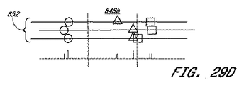
図14に示す一つの実施形態では、撮像装置は32個の要素を含む。詳細には、図14は、一つの送信機(送信機16)が信号506をオブジェクト504に送信して、32個の受信機(1〜32)が検出する反射波510が生成される構成の実施形態の放射図500を示している。受信機群502に向かって伝播する反射波510は反射放射波508によって表わされ、波面510が放射波508と交差する交点は放射波508の同相部分を表わす。
In one embodiment shown in FIG. 14, the imaging device includes 32 elements. Specifically, FIG. 14 shows a configuration in which one transmitter (transmitter 16) transmits a
例示としての実施形態500では、送信信号506を表わす指標iTxは32個の受信機群が使用するサンプリング指標の全てに共通する。オブジェクトがアレイ502の中間の高さに位置する特定の例では、反射波510は受信機16に最初に到達する。従って、オブジェクト504が位置するピクセルに関連するサンプリング指標は或る値を有し、この値によって受信機16からの信号が最初にサンプリングされる。その後、受信機15及び17からの信号がサンプリングされ、次に受信機14及び18からの信号がサンプリングされ、残りの信号も同様にサンプリングされることになる。受信機32からの信号は、波面510の余分の伝播距離に対応する時間に、最後にサンプリングされることになる。
In the
図15に示す一つの実施形態では、撮像装置は32個の要素を含む。詳細には、図15は、32個全ての送信機が信号群526をオブジェクト524に送信して受信機16が検出する反射信号528が生成される構成の実施形態の放射図520を示している。例示としての実施形態520では、反射信号528を表わす指標iRxは32個の受信機に関連するサンプリング指標の全てに共通する。
In one embodiment shown in FIG. 15, the imaging device includes 32 elements. Specifically, FIG. 15 shows a radiation diagram 520 of an embodiment in which all 32 transmitters transmit a
オブジェクトがアレイ502の中間の高さに位置する特定の例では、送信機16からの送信信号がオブジェクト524に最初に到達する(全ての信号が同時に送信されると仮定する)。従って、オブジェクト524が位置するピクセルに関連するサンプリング指標は或る値を有し、この値によって最初のサンプリング信号が送信機16に関連付けられる。次のセットのサンプリング信号が送信機15及び17に関連付けられ、残りのセットのサンプリング信号も同様に関連付けられる。最後のセットのサンプリング信号は送信機32に関連付けられることになる。
In the particular example where the object is located at an intermediate height of the array 502, the transmitted signal from the
図13を参照しながら前に説明したように、複数の信号を送信機群から異なる方法によって送信することができる。信号群を複数の送信機から順番に送信することにより、信号群のオブジェクト524への到達だけでなく、その後の反射信号群の受信機への到達を時間的に分離することができる。信号送信を順番に行なう一つの方法では、送信を送信機16から始め、次に所定時間が経過したときに送信を送信機15及び17から行ない、残りの送信も同様に行なう。このように送信を順番に行なうことにより、受信機群522のアレイに関連するサンプリングの時間間隔を長くすることができる。
As described above with reference to FIG. 13, multiple signals can be transmitted from the transmitter group in different ways. By transmitting the signal group sequentially from a plurality of transmitters, not only the arrival of the signal group to the
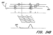
図16は、複数のトランスデューサによるサンプリングによってどのようにして、これらのトランスデューサの各々に関連するサンプリングレートよりも高い実効サンプリングレートが得られるかについて示している。例示としての動作構成600では、送信機602が、送信信号606に従って送信エネルギー604を媒質(図示せず)に伝達するものとして描かれている。送信信号606は周期信号として描かれているが、このような特徴は必須ではない。送信信号606は、或る時間特性パターンを有する波形であればどのような波形とすることもできる。例えば、送信信号606がシングルパルスである場合、当該信号を当該パルスの時間幅として特徴化することができる。
FIG. 16 shows how sampling by multiple transducers can yield an effective sampling rate that is higher than the sampling rate associated with each of these transducers. In the exemplary operational configuration 600, the
例示としての動作構成600は更に複数の受信機610を含み、これらの受信機は対応する反射エネルギー612を受信する。反射エネルギー612に従って、これらの受信機610はサンプリングされた個別の信号群614を出力する。この例では、複数の受信機610に対するサンプリングは、説明を分かり易くするために同時に行なわれるものとして示される。受信機信号群を同時にサンプリングする操作は必須ではないことを理解し得る。 The exemplary operating configuration 600 further includes a plurality of receivers 610 that receive the corresponding reflected energy 612. Depending on the reflected energy 612, these receivers 610 output a sampled group of signals 614. In this example, sampling for multiple receivers 610 is shown as being done simultaneously for ease of explanation. It can be appreciated that the operation of simultaneously sampling the receiver signals is not essential.
同様に、説明を分かり易くするために、共通サンプリングが、送信信号周期Tsignalのほぼ半分である周期Tsamplingで行なわれるものとして示される。従って、このような状態におけるサンプリング周波数は送信信号周波数の約2倍となる。一般的に、サンプリング周波数は解析対象の信号の周波数の少なくとも2倍にして、当該信号の特性化が可能になるようにする必要があり、「2倍」という最低限界はナイキスト限界と呼ばれることが多い。 Similarly, for ease of explanation, the common sampling is shown as being performed with a period T sampling which is approximately half the transmission signal period T signal . Therefore, the sampling frequency in such a state is about twice the transmission signal frequency. In general, the sampling frequency should be at least twice the frequency of the signal to be analyzed so that the signal can be characterized, and the minimum limit of “twice” is called the Nyquist limit. Many.
図16に示すように、受信機群610が出力する例示としての信号群614は、基礎となる「キャリア」信号波形(図を分かり易くするために重ねている破線曲線)を有するものとして示され、この信号波形は送信信号606と同様の波形を有することができる。信号群614は、キャリア信号波形の周りに複数の摂動(perturbations)を含む。このような摂動は送信信号606が媒質中の或る注目構造と相互作用する結果として現われるか、またはバックグランドノイズに起因する。原因が何であるにせよ、このような摂動は、キャリア信号波形またはサンプリング周期と比較すると、波長以下のパターンサイズを有する(かつ有するものとして描かれる)。従って、個々の受信機に対するサンプリングだけでは、ノイズまたは正規の信号に関連する微細なパターン波形を分解することができない。
As shown in FIG. 16, the exemplary signal group 614 output by the receiver group 610 is shown as having an underlying “carrier” signal waveform (dashed curve superimposed for clarity of illustration). This signal waveform can have a waveform similar to that of the
複数の受信機を使用する場合、これらの受信機は反射エネルギーが受信機群に異なる時間に到達するように配置することができる。このような到達時間の差は、媒質の異方性によって生じる経路長差及び/又は速度差に起因する伝播時間の差によって発生させることができる。図16では、このような到達時間の差は、受信機610a及び610bに関してΔTと表わされる。所定の受信機ペアでは、到達時間差ΔTはサンプリング周期Tsamplingまたは送信信号周期Tsignalよりもずっと短くすることができる。
When using multiple receivers, these receivers can be arranged so that the reflected energy reaches the receivers at different times. Such a difference in arrival time can be caused by a difference in propagation time caused by a path length difference and / or a speed difference caused by anisotropy of the medium. In FIG. 16, such a difference in arrival time is represented as ΔT for
受信機群をアレイ状に配列することにより、連続的な到達時間差を受信機群に生じさせることができる。従って、受信機群に対して同時にサンプリングすることにより、個々の受信機群に関して、受信信号群の異なる時間部分をサンプリングすることができるという効果が得られる。従って、例示としての構成600では、同時サンプリングを時間t1で同時に行なうことによって、例示としての信号614c(遅れて到達する)がキャリア波形の所定の時間部分(この例ではサイクルの最初の部分)でサンプリングされる。サンプリングを時間t1で行なうことによって、例示としての信号614bがキャリア波形の内、受信機610bと610cとの間の到達時間差にほぼ等しい時間の時間部分でサンプリングされる。同様に、サンプリングを時間t1で行なうことによって、例示としての信号614aがキャリア波形の内、受信機610aと610bとの間の到達時間差にほぼ等しい時間の時間部分でサンプリングされる。受信機610a,b,及びcに対するサンプリングを組み合わせる場合、結果として得られる測定値は、共通サンプリング間隔Tsamplingよりもずっと短い到達時間差ΔTの間隔で行なわれるサンプリングと等価な測定値とすることができる。
By arranging the receiver groups in an array, continuous arrival time differences can be generated in the receiver groups. Therefore, by simultaneously sampling the receiver group, it is possible to sample different time portions of the received signal group for each receiver group. Thus, in the example configuration 600, by performing simultaneous sampling at time t1, the example signal 614c (arriving late) is a predetermined time portion of the carrier waveform (in this example, the first part of the cycle). Sampled. By sampling at time t1, the exemplary signal 614b is sampled in the time portion of the carrier waveform that is approximately equal to the arrival time difference between the
受信機の数、及び/又は到達時間差は、実効サンプリング間隔が2つの共通サンプリング区間の間に(例えば、図16の同時サンプリング時間t1とt2との間に)分布するように選択することができることが分かる。従って、構成を適正に行なうことにより、受信機アレイを使用して受信信号群を共通サンプリング周波数よりもずっと高い周波数でサンプリングすることができるので、キャリア信号波形に「乗る」高い周波数(送信信号周波数よりも)の摂動信号成分を分解することができる。 The number of receivers and / or arrival time differences can be selected such that the effective sampling interval is distributed between two common sampling intervals (eg, between the simultaneous sampling times t1 and t2 in FIG. 16). I understand. Therefore, with proper configuration, the receiver array can be used to sample the received signal group at a frequency much higher than the common sampling frequency, so the carrier signal waveform “rides” a higher frequency (transmit signal frequency). Can be decomposed.
高い周波数の摂動パターンの抽出を可能にするために、一つの実施形態では、受信信号群をフィルタリングしないことが好ましい。或る従来のシステムでは、フィルタリングを使用して高い周波数の摂動を除去する。しかしながら、このようなフィルタリングを行なうと、注目する相互作用によって引き起こされる摂動がノイズ摂動とともに除去されてしまう。 In order to allow the extraction of high frequency perturbation patterns, in one embodiment it is preferred not to filter the received signals. Some conventional systems use filtering to remove high frequency perturbations. However, such filtering removes perturbations caused by the interaction of interest along with noise perturbations.
受信信号群を上述のような実質的に高い周波数でサンプリングすることが、撮像法を改善する一つの態様であることが分かる。このようなサンプリングによって、注目する摂動及びノイズの両方をサンプリングする。従って、撮像法を改善する別の態様は、異なる受信機に対するサンプリングを組み合わせて、サンプリングされる摂動の信号対雑音比が大きくなるような方法である。 It can be seen that sampling the received signal group at a substantially high frequency as described above is one aspect of improving the imaging method. With such sampling, both the perturbation and noise of interest are sampled. Thus, another way to improve imaging is to combine sampling for different receivers to increase the signal to noise ratio of the sampled perturbations.
図17は、複数の受信機に対するサンプリングを組み合わせて、媒質による注目反射によって生成される比較的弱い信号をどのようにして強くするかについての例を示している。複数の例示としての信号セグメント群620がキャリア信号(破線曲線622)に重なるように示される。例示としての信号セグメント群620の各々は、当該セグメント固有セットのノイズ波形の中に、比較的弱い注目信号626を含むものとして示される。各信号は異なるノイズ波形を有することができる。その理由は、信号は他の信号群とは異なる経路を表わすからである。信号内部の摂動が、複数の信号620の少なくともかなり広い部分に渡って観察される場合には必ず、このような摂動は、或る注目相互作用が媒質の中で生じることに起因して生じ得るのであり、かつこれらの信号に関連付けることができる。
FIG. 17 shows an example of how to strengthen the relatively weak signal generated by the reflection of interest by the medium by combining sampling for multiple receivers. A plurality of exemplary signal segment groups 620 are shown overlapping the carrier signal (dashed curve 622). Each of the exemplary signal segment groups 620 is shown as including a relatively weak signal of
図16を参照しながら説明したように、このような比較的微細なパターンの摂動は、正規の信号またはノイズであるかどうかに関係なく、共通サンプリング周波数のサンプリングレートよりもずっと高くすることができる実効サンプリングレートでサンプリングされる可能性が高くなる。従って、複数のこのような実効サンプリングの例を、破線624により示す。ここで、図17の実効サンプリングライン624は、正しい相関が行なわれる場合には、複数の信号620によって、注目摂動を周囲ノイズ摂動に対して強調することができることを明示するためにのみ示されていることを理解し得る。このような信号サンプリングの相関を作り出す方法については後で更に詳細に説明する。 As described with reference to FIG. 16, such a relatively fine pattern perturbation can be much higher than the sampling rate of the common sampling frequency, regardless of whether it is a regular signal or noise. The possibility of being sampled at the effective sampling rate is increased. Accordingly, a plurality of examples of such effective sampling are indicated by dashed line 624. Here, the effective sampling line 624 of FIG. 17 is shown only to demonstrate that the perturbation of interest can be enhanced with respect to ambient noise perturbations by the plurality of signals 620 if correct correlation is performed. I can understand that. A method of creating such a signal sampling correlation will be described in more detail later.
また、図17の注目摂動626は、説明を分かり易くするためにピーク近傍でサンプリングされるものとして描かれていることを理解し得る。受信機群における到達時間差(ΔT)は均一ではない可能性があるので、効果的な増加サンプリングの間の間隔は均一ではない可能性がある。その結果、摂動626に対するサンプリングは摂動ピーク波形の異なる部分で行なわれる可能性がある。一つの実施形態では、このような現象が、効果的な増加サンプリングによって実現する分解能を制限することになる。
In addition, it can be understood that the
一つの実施形態では、選択受信機群からの正しく相関させたアナログ信号は、互いに干渉させることができる。このような実施形態では、種々のアナログ信号に遅延を、信号群を相関させる方法に従って付加することができる。 In one embodiment, correctly correlated analog signals from selected receivers can interfere with each other. In such embodiments, delays can be added to the various analog signals according to the method of correlating signals.
一つの実施形態では、選択受信機群からの生の信号群を同時サンプリングの間にデジタル化する。従って、複数の受信機、及びこれらの受信機に接続されるサンプリング電子機器は、これらの機器の個別の信号の時間部分を効果的にサンプリングし、デジタル化している。図17には、デジタル化の結果を相関させ、合成して合成データ列628を生成する様子が示される。信号群に対するデジタル化の結果が正しく合成される場合、注目摂動626の個々のデジタル値が合成されて、強調されたデジタル値が生成される。これとは異なり、サンプリングされ、かつデジタル化されたノイズは合成されて互いに平均的にほぼ相殺される、または相関摂動値630よりも小さくなるように合成される。
In one embodiment, raw signals from selected receivers are digitized during simultaneous sampling. Thus, multiple receivers and the sampling electronics connected to these receivers effectively sample and digitize the time portion of the individual signals of these devices. FIG. 17 shows how the digitized results are correlated and combined to generate a combined
基本的に、信号群の合成は、アレイのいずれの受信機群に対しても行なうことができる。しかしながら、本出願人の経験から、送信機群及び受信機群の或る組み合わせからの信号群を相関させ、合成することによって画質に関して更に良好な結果が得られることが分かっている。 In principle, signal grouping can be done for any receiver group in the array. However, Applicants' experience has shown that better results in terms of image quality can be obtained by correlating and combining signals from certain combinations of transmitters and receivers.
図18A及び18Bは、このような送信機−受信機の組み合わせの2つの例を示している。図18Aでは、例示としての動作構成640において、i番目の送信機642aがエネルギー646を送信し、1要素に相当する間隔だけオフセットして位置する受信機(i+1)644bが反射信号648を(媒質中の任意のポイント658から)受信し、信号を生成する。従って、送信機(i+1)642bからのエネルギー650はエネルギー652として反射され、受信機(i+2)644cが受信する。同様に、送信機(i+2)642cからのエネルギー654はエネルギー656として反射され、受信機(i+3)644dが受信する。一つの実施形態では、トランスデューサ間のこのような送信機−受信機の組み合わせを1単位だけオフセットすることにより、媒質中の任意のポイント658に対するほぼ「真正面(head−on)」タイプの探索が可能になる。
18A and 18B show two examples of such transmitter-receiver combinations. In FIG. 18A, in the
図18Bでは、例示としての動作構成640において、i番目の送信機642aがエネルギー662を送信し、2要素に相当する間隔だけオフセットして位置する受信機(i+3)644cが反射信号664を(媒質中の任意のポイント658から)受信し、信号を生成する。従って、送信機(i+1)642bからのエネルギー666はエネルギー668として反射され、受信機(i+3)644dが受信する。このようにオフセットすることによって、媒質中のポイント658に対して更に大きい角度で探索することができる。
In FIG. 18B, in the
送信機及び受信機に関するこのようなオフセットペアは3,4,またはそれ以上のオフセット単位に拡張することができることが分かる。基本的に、アレイではどのようなオフセットも使用することができる。或る用途においては、このような機能を使用して所定のオブジェクトから隣接角度方向に向かう反射及び/又は放射を分析することができる。 It can be seen that such offset pairs for the transmitter and receiver can be extended to 3, 4, or more offset units. Basically any offset can be used in the array. In some applications, such a feature can be used to analyze reflections and / or radiations from a given object toward adjacent angular directions.
図19〜21は、サンプリング及び合成を、異なる送信機−受信機のオフセットからの信号群に対して行なう種々のプロセスを示している。図19は、送信を選択送信機群から順番に行なうプロセス680の一つの実施形態を示している。一つの実施形態では、マスター時間基準をプロセスブロック682において指定する。このようなマスター時間を使用して後続の時間関連動作の基準とすることができる。次に、プロセス680は選択送信機群をループスルーする(開始ループ684及び終了ループ694)。プロセスブロック686では、プロセス680は現在の送信機にエネルギーを媒質に伝達させる。プロセスブロック688では、戻り信号群を選択受信機群が受信する。一つの実施形態では、受信機群の全てが、これらの受信機に衝突する戻り信号群を受信する。プロセスブロック690では、プロセス680は選択受信機群からの結果データをサンプリングし、保存する。一つの実施形態では、プロセス680は、次の送信機から送信する前に選択期間に渡って待機する。
FIGS. 19-21 illustrate various processes for performing sampling and combining on signal groups from different transmitter-receiver offsets. FIG. 19 shows one embodiment of a
図20は、サンプリングデータを異なる送信機−受信機のオフセットグループに従って合成するプロセス700の一つの実施形態を示している。プロセス700は、注目する送信機と受信機との間のオフセットNの異なる値をループスルーする(開始ループ702及び終了ループ708)。一つの実施形態では、オフセットNの値は0(ゼロ)〜Nmaxの範囲であり、N=0は、受信機が送信機と同じアセンブリに含まれる場合を表わす。プロセスブロック704では、プロセス700は、選択送信機群から、現在値Nだけオフセットする受信機群からのデータを合成することによりデータ「ページ」を作成する。プロセスブロック706では、プロセスは、現オフセット値Nに対応するデータページを保存する。
FIG. 20 illustrates one embodiment of a
図21は、データページ(群)を使用して媒質を特徴付けるプロセス710の一つの実施形態を示している。プロセスブロック712では、プロセス710は、送信機−受信機のオフセット値(群)Nに対応する選択データページ(群)を取り出す。プロセスブロック714では、プロセス710は、選択データページ(群)を合成して媒質を特徴付ける。一つの実施形態では、媒質を特徴付けにより、媒質の画像が形成される。
FIG. 21 illustrates one embodiment of a
図22〜25は、送信機−受信機のペア群のオフセットに基づくデータページ作成の特定の例を示している。例示による説明を分かり易くするために、6セットの送信機−受信機のアセンブリ732を有する例示としての動作構成730を図22に示す。このような構成は単に説明を分かり易くするためのものであり、決して本発明の技術範囲を制限するためのものではないことを理解し得る。
FIGS. 22-25 show specific examples of data page creation based on the offset of the transmitter-receiver pair group. For ease of illustration by way of example, an exemplary
一つの実施形態では、送信機−受信機の各アセンブリは送信機(Tx)、及び当該送信機に近接して位置する受信機(R)を含む。矢印734で示すように、6個の例示としての送信機(Tx1〜Tx6)は、第1送信機Tx1から順番に「送信を行なう」。
In one embodiment, each transmitter-receiver assembly includes a transmitter (Tx) and a receiver (R) located proximate to the transmitter. As shown by
更に図22に示すのは、媒質中の任意のポイント736である。一つの実施形態では、所定の送信機は、ポイント736を含む媒質からの戻り信号が受信機群の全てに戻る時間が経過してしまうまで送信を行なわない。任意のポイント736は、説明を分かり易くするために示され、アレイ732に対する当該ポイントの位置についての先験的な認識または仮定は必要ではないことを理解し得る。
Further shown in FIG. 22 is an
図23A及び23Bは、図22の6個の例示としての受信機群が、所定の送信機に起因する反射信号群の受信に応答するときに生成される生の簡易アナログトレースの例を示している。特定の摂動ピークが異なるトレースの異なる時間部分で生じる様子を説明するために、これらのトレースはピークを示すためにのみ描かれている。ここで、図16及び17を参照しながら上に説明したように、これらのトレースには他の摂動パターンが生じ得ることを理解し得る。 FIGS. 23A and 23B show examples of raw simplified analog traces generated when the six exemplary receiver groups of FIG. 22 respond to reception of reflected signal groups resulting from a given transmitter. Yes. To illustrate how specific perturbation peaks occur at different time portions of different traces, these traces are only drawn to show the peaks. It can now be appreciated that other perturbation patterns can occur in these traces, as described above with reference to FIGS.
図23Aは、Tx1からの送信に関連する例示としてのトレース群750を示している。一つの実施形態では、これらのトレース750の各々は、マスター時間基準を基準にしながら「開始」時間と「停止」時間との間でサンプリングされる。従って、摂動ピークが図22のポイント736によって生じるものであると仮定すると、第2受信機R2への到達が、当該受信機が他の受信機群よりもTx1に近いので可能になる。他の受信機群は同じポイント736による摂動を後続の連続する時点で、ポイント736に対するこれらの受信機の配置に起因して受けることになる。到達時間の差はまた、媒質中の音の速度の変化によって影響され得る。原因が何であるにせよ、到達時間は、注目受信機群の各々に関して補正される必要があり、この場合、これらの注目受信機群からの信号群(またはデジタルデータ)が合成される。このような補正を行なう一つの方法については後で更に詳細に説明する。
FIG. 23A shows an
図23Bは、i番目の送信機Tx(i)からの送信に関連する例示としてのトレース群760を示している。同様に、サンプリングされるこれらのトレース760の各々は、時間基準を基準にしながら「開始」時間と「停止」時間との間でサンプリングすることができる。時間基準は、図23Aを参照しながら上に説明したマスター時間基準と同じとすることもできるが、必ずしも同じとする必要はない。例示としてのポイント736が第2受信機R2に近接しているので、摂動信号はR2に最初に到達することができ、その後連続してR2から離れた他の受信機群に到達することが分かる。トレース群760内での到達時間も、以下に説明する方法によって補正することができる。
FIG. 23B shows an
図23A及び23Bから、異なる送信機に関連する、異なる「セット」から得られる信号トレース群(生の、またはデジタル化された)は合成することができることが分かる。従って、受信機群の対応する送信機群から1単位だけオフセットする位置の受信機群が受信する戻り信号を解析しようとする場合、トレース群750のうちのR2トレースはトレース群760のうちのトレース(i+1)と合成することができる(例えば、i=3の場合、R2及び/又はR4のトレースを選択する)。これらの信号をこのような方法で合成することにより、送信機群に関する同様の「見通し(perspective)」をほぼ維持しながら摂動信号を強調することができる。
It can be seen from FIGS. 23A and 23B that signal trace groups (raw or digitized) from different “sets” associated with different transmitters can be combined. Therefore, when trying to analyze the return signal received by the receiver group at a position offset by one unit from the corresponding transmitter group of the receiver group, the R2 trace of the
図24及び25は、図22の例示としての動作構成に関連する、オフセット1のデータ及びオフセット2のデータの特定の可能な組み合わせの例を示している。異なる送信機に関連するトレース群の合成について説明するために、これらのトレースを既にデジタル化されているものとして簡易化した形で描いている。従って、これらのトレースのスパイクはサンプリングされた摂動信号群(図23A及び23Bの)のデジタル値を表わす。 FIGS. 24 and 25 illustrate examples of certain possible combinations of offset 1 data and offset 2 data associated with the exemplary operational configuration of FIG. To illustrate the synthesis of trace groups associated with different transmitters, these traces are drawn in a simplified form as already digitized. Thus, the spikes in these traces represent the digital values of the sampled perturbation signal group (of FIGS. 23A and 23B).
図24A〜24Fは、6個の例示としての送信機の各々に関連する受信機群から得られるサンプリングデータトレース群を示している。図25A〜25Fは、同じサンプリングデータトレース群を示している。 24A-24F show a sampling data trace group obtained from the receiver group associated with each of the six exemplary transmitters. 25A-25F show the same sampling data trace group.
図24A〜24F及び24Gは、オフセット1のデータの可能な合成結果を示し、図25A〜25F及び25Gは、オフセット2のデータの可能な合成結果を示している。従って、送信機群の各々に関連する受信機群から得られる同じセットのデータトレース群を異なるオフセット組み合わせに使用することができることが分かる。更に、オフセット3、オフセット4、または他のいずれかの番号Xが付されるオフセットXは、図24及び25を参照しながら説明される方法と同様の方法により実現することができる。 24A-24F and 24G show possible synthesis results for offset 1 data, and FIGS. 25A-25F and 25G show possible synthesis results for offset 2 data. Thus, it can be seen that the same set of data trace groups obtained from the receiver group associated with each of the transmitter groups can be used for different offset combinations. Furthermore, the offset X to which the offset 3, the offset 4, or any other number X is attached can be realized by a method similar to the method described with reference to FIGS.
送信機Tx1を使用する場合、図24Aに示すように、R2がオフセット1の受信機である。送信機Tx2を使用する場合、図24Bに示すように、R1及びR3がオフセット1の受信機であるので、受信機群のいずれか、または両方からのデータを使用することができる。同様に、他の送信機群に対応するオフセット1の受信機群を図24C〜24Fに示す。 When the transmitter Tx1 is used, R2 is an offset 1 receiver as shown in FIG. 24A. When using transmitter Tx2, as shown in FIG. 24B, R1 and R3 are offset 1 receivers, so data from either or both receiver groups can be used. Similarly, offset 1 receiver groups corresponding to other transmitter groups are shown in FIGS.
図24Gは合成データ772を示し、この合成データはオフセット1の受信機群に関するデータ770a〜fを合成した結果である。これらのデータが正しく合成される場合、合成データ772は注目構造に対応する強調ピーク774を含むことができる。このような合成を行なう方法については後で更に詳細に説明する。 FIG. 24G shows combined data 772, which is the result of combining data 770a-f for the receiver group at offset 1. If these data are correctly combined, the combined data 772 can include an emphasis peak 774 corresponding to the structure of interest. A method for performing such synthesis will be described in more detail later.
図25A〜25F及び25Gは、オフセット2のデータの可能な合成方法を示している。送信機Tx1を使用する場合、図25Aに示すように、R3がオフセット2の受信機である。送信機Tx2を使用する場合、図25Bに示すように、R4がオフセット2の受信機である。送信機Tx3を使用する場合、図25Cに示すように、R1及びR5がオフセット2の受信機である。従って、受信機群のいずれか、または両方からのデータを使用することができる。同様に、他の送信機群に対応するオフセット2の受信機群を図25D〜25Fに示す。 25A-25F and 25G show possible synthesis methods for offset 2 data. When the transmitter Tx1 is used, R3 is an offset 2 receiver as shown in FIG. 25A. When the transmitter Tx2 is used, R4 is a receiver with an offset 2 as shown in FIG. 25B. When the transmitter Tx3 is used, R1 and R5 are offset 2 receivers as shown in FIG. 25C. Thus, data from either or both receiver groups can be used. Similarly, receiver groups with offset 2 corresponding to other transmitter groups are shown in FIGS.
図25Gは合成データ782を示し、この合成データはオフセット2の受信機群に関するデータ780a〜fを合成した結果である。これらのデータが正しく合成される場合、合成データ782は注目構造に対応する強調ピーク784を含むことができる。このような合成を行なう方法については後で更に詳細に説明する。 FIG. 25G shows combined data 782, which is the result of combining data 780 a-f regarding the receiver group at offset 2. If these data are synthesized correctly, the synthesized data 782 can include an emphasis peak 784 corresponding to the structure of interest. A method for performing such synthesis will be described in more detail later.
他の受信機オフセット(3,4など)のデータを同様の方法によって合成することもできることが分かる。従って、オフセット1の構成及びオフセット2の構成に関する例示としての説明は決して本発明の技術範囲を制限するものではないことを理解し得る。 It can be seen that data for other receiver offsets (3, 4, etc.) can be combined in a similar manner. Accordingly, it can be understood that the exemplary descriptions regarding the configuration of offset 1 and the configuration of offset 2 are in no way intended to limit the scope of the present invention.
次に、図26〜33は、異なる受信機からの信号群をどのようにして合成すれば注目する強調信号を生成することができるかについて示している。異なる受信機はオフセット受信機(offset receivers)とすることもできるし、または単に複数の受信機の一部分とすることもできることを理解し得る。 Next, FIGS. 26 to 33 show how an emphasized signal of interest can be generated by combining signal groups from different receivers. It can be appreciated that the different receivers can be offset receivers or can simply be part of multiple receivers.
図26は、所定の受信機792が、図16及び17を参照しながら上に説明した微弱な摂動を有する例示としての信号796を出力する様子を示している。受信機信号796のような受信機信号は、受信機792に、当該受信機のほぼ真正面の方向を含む複数の方向から衝突する戻り信号群802から生じ得る。受信機のほぼ真正面の方向に延びる仮想ライン790を図26に示す。説明を分かり易くするために、ライン790はレイヤ794と交差するように描かれている。ライン790及びレイヤ794は直交するように描かれているが、向きのこのような関係は必須ではないことを理解し得る。一つのラインを当該レイヤに対して或る角度で傾けることができる。更に、一つのレイヤは平板状である必要はなく、当該レイヤを屈曲させ、貝殻様(shell−like)構造の一部分を受信機の近傍で構成することができる。
FIG. 26 illustrates how a given
一つの実施形態では、受信機信号群を合成してほぼライン790に沿って、レイヤ794の内部に位置する摂動構造を強調するか、または摂動構造に「フォーカス」を設定する。複数の受信機からの信号群に対するこのような「フォーカス」合成(“focused” combination)は、受信機792に関連する一つのスキャンラインと考えることができる。従って、複数の受信機に関連する複数のこのようなスキャンラインはスキャンライン群に沿った一つの画像を形成することができる。
In one embodiment, the receiver signals are combined to emphasize the perturbation structure located within
図27は、複数の受信機810a〜cに関連する複数の例示としてのスキャンライン812a〜cが例示としてのレイヤ814と交差する様子を示している。このような交差部分によって定義される領域群は必ずしも一つの「ピクセル」と等価ではないことを理解し得る。或る用途では、一つのピクセルのサイズによって或る制限が当該ピクセルから生成される画像の解像度に、検出器が更に高い分解能を備えるかどうかに関係なく課される。
FIG. 27 illustrates how the
図27では、例示としての領域818はスキャンライン812b及びレイヤ814によって定義される交差領域として定義される。一つの実施形態では、このような領域によって、フォーカスが行なわれる一つの窓(または、スキャンラインのフィールド深度)が定義される。一つの実施形態では、領域がこれ以上分割されることがない場合、当該領域は撮像を行なうための一つのピクセルと見なすことができる。
In FIG. 27,
一つの実施形態では、前述の方法によって定義されるフォーカス領域のサイズは固定する必要はない。以下に更に詳細に説明するように、レイヤ814をまず、相対的に大きくなるように選択することができる。一旦、「粗フォーカス」がこのような一つのレイヤに関して行なわれると、当該レイヤを更に薄いレイヤに分割することができる。従って、スキャンライン(群)を必要に応じて、及び/又は可能な場合に「微細フォーカス」を行なうことができる。従って、図27に示すように、レイヤ814は、例示としてのレイヤ816のような更に薄いレイヤ群に分割することができ、フォーカス領域820が相対的に薄い当該レイヤに関連付けられることになる。
In one embodiment, the size of the focus area defined by the method described above need not be fixed. As will be described in more detail below, the
図28〜30は、例示としての3個の受信機に関連するスキャンラインをどのようにして異なるレイヤにフォーカスを設定することができるかについて例を挙げて示している。説明を分かり易くするために、3個の受信機810a〜cの例示としてのアレイを図28A,29A,及び30Aに示す。受信機810a〜cに関連付けられるのは、これらの受信機からそれぞれ延びる仮想ライン812a〜cである。説明を分かり易くするために、ライン812a〜cを3つの例示としてのレイヤ822a〜cに分割する。説明を分かり易くするために更に、第1注目構造824が、ライン812a及びレイヤ822bによって定義される領域にほぼ位置するものとして示される。第2注目構造826は、ライン812b及びレイヤ822aによって定義される領域にほぼ位置するものとして示される。第3注目構造828は、ライン812c及びレイヤ822cによって定義される領域にほぼ位置するものとして示される。異なる注目構造をどのようにしてサンプリング時間に関してシフトさせることができるかについて示すために、3つの注目構造を三角形824、円形826、及び方形828として描いている。
FIGS. 28-30 illustrate by way of example how the scan lines associated with the three exemplary receivers can be focused on different layers. For ease of explanation, an exemplary array of three
図28B,29B,及び30Bも同じであり、それぞれの受信機810a〜cに関連するデータトレース830a〜cに基づいて、3つの例示としての注目構造824,826,及び828が相対的に異なる時間に「どのように見える」かについて示している。例えば、三角形824は受信機810aのほぼ真正面に、かつ最も近くに位置する。従って、受信機810aに関連するデータトレース830aが示すように、受信機810aが戻り信号を三角形824から最初に受信することができ、次に受信機810bが受信し、今度は受信機810cが受信する。同様に、円形826は受信機810bのほぼ真正面に、かつ最も近くに位置する。従って、データトレース830bが示すように、受信機810bが戻り信号を円形826から最初に受信することができ、その後、受信機810a及び810cが受信する。
28B, 29B, and 30B are the same, based on the data traces 830a-c associated with the
図28A,29A,及び30Aに示すように、受信機810a〜cは順番に配置される構成で表示されている。このような表示は、戻り信号が異なる受信機に到達する相対到着時間の概念、及びこのような信号を合成してフォーカススキャンライン(focused scanline)を形成することができる様子を示すためにのみ行なわれていることを理解し得る。詳細には、例示としての受信機810a〜cが順番に並ぶように示されているが、これらの受信機は必ずしもこのように物理的に並んでいる必要はないことを理解し得る。例えば、異なる受信機オフセットデータを上に説明したように合成することができ、このような状態においては、合成される信号を有する受信機群は互いに隣り合うか、または非常に近接している必要はない。従って、受信機810a〜cの配置は、説明を分かり易くするために論理的配置を表していると解釈され得る。
As shown in FIGS. 28A, 29A, and 30A, the
図28Cは、受信機810aに関連するスキャンライン834の例示としてのフォーカスレイヤ838aを示している。スキャンライン834と共に表示されるのは、スキャンラインにフォーカスが設定されているときの3つの構造824,826,828からの合成戻り信号に関連する相対ピーク高さ836である。フォーカスを行なうための戻り信号トレース群に対する相対シフトは、1セット832のシフトトレースとして示される。なお、フォーカスを行なうために、一つのトレースを別のトレースに対して予めどれだけシフトすべきかについて求めておく必要はない。シフト動作を異なる形で組み合わせることにより、フォーカス設定されている状態を決定する方法については以下に更に詳細に説明する。このようなフォーカス設定を所定のスキャンラインに対して行なった結果を図28〜30を参照しながら説明するために、複数のスキャンラインにフォーカスが設定される様子が描かれている。
FIG. 28C shows an exemplary focus layer 838a for the
同様に、図28Dは、受信機810aに関連するスキャンライン834の例示としてのフォーカスレイヤ838bを示している。スキャンライン834と共に表示されるのは、スキャンラインにフォーカスが設定されているときの3つの構造824,826,828からの合成戻り信号に関連する相対ピーク高さ836である。フォーカスを行なうための戻り信号トレース群に対する相対シフト動作は、1セット840のシフトトレースとして示される。
Similarly, FIG. 28D shows an exemplary focus layer 838b for
同様に、図28Eは、受信機810aに関連するスキャンライン834の例示としてのフォーカスレイヤ838cを示している。スキャンライン834と共に表示されるのは、スキャンラインにフォーカスが設定されているときの3つの構造824,826,828からの合成戻り信号に関連する相対ピーク高さ836である。フォーカスを行なうための戻り信号トレース群に対する相対シフト動作は、1セット844のシフトトレースとして示される。
Similarly, FIG. 28E shows an exemplary focus layer 838c for
図28Dでは、フォーカスレイヤ838bによって、三角形824の位置合わせ(データトレース群を正しくシフトさせることにより)に対応する強調ピーク842が生成されることが分かる。このような強調ピークを利用して、スキャンラインにフォーカスが所定のレイヤにおいて設定されているかどうかを判断することができる。このような判断について以下に更に詳細に説明する。
In FIG. 28D, it can be seen that the focus layer 838b generates an
受信機810aに関連するライン812aに関して、第1レイヤ822a及び第3レイヤ822cは、いかなる構造も含まない。従って、スキャンラインに正しくフォーカスを設定することにより得られる画像には、2つのレイヤ822a及び822cの構造群が表示されてはならない。一つの実施形態では、このような結果は、閾値カット(threshold cut)を所定のフォーカスレイヤのピーク(群)に対して行なって、当該閾値を下回るピーク群が画像情報として処理されることがないようにすることにより得られる。例えば、強調ピーク842を取り込み、それよりも小さいピークを排除するように閾値を設定した場合、第1フォーカスレイヤ838a及び第3フォーカスレイヤ838cはほとんど画像の無いフォーカス領域を形成する。
With respect to
図29Cは、受信機810bに関連するスキャンラインに関する例示としてのフォーカスレイヤ848aを示している。スキャンラインと共に表示されるのは、スキャンラインにフォーカスが設定されているときの3つの構造824,826,828からの合成戻り信号に関連する相対ピーク高さである。フォーカスを行なうための戻り信号トレース群に対する相対シフト動作は、1セット846のシフトトレースとして示される。
FIG. 29C shows an exemplary focus layer 848a for the scan line associated with
同様に、図29Dは、受信機810bに関連するスキャンラインに関する例示としてのフォーカスレイヤ848bを示している。スキャンラインと共に表示されるのは、スキャンラインにフォーカスが設定されているときの3つの構造824,826,828からの合成戻り信号に関連する相対ピーク高さである。フォーカスを行なうための戻り信号トレース群に対する相対シフト動作は、1セット852のシフトトレースとして示される。
Similarly, FIG. 29D shows an exemplary focus layer 848b for the scan line associated with
同様に、図29Eは、受信機810bに関連するスキャンラインに関する例示としてのフォーカスレイヤ848cを示している。スキャンラインと共に表示されるのは、スキャンラインにフォーカスが設定されているときの3つの構造824,826,828からの合成戻り信号に関連する相対ピーク高さである。フォーカスを行なうための戻り信号トレース群に対する相対シフト動作は、1セット854のシフトトレースとして示される。
Similarly, FIG. 29E shows an exemplary focus layer 848c for the scan line associated with
図29Cでは、フォーカスレイヤ848aによって、円形826の位置合わせ(データトレース群を正しくシフトさせることにより)に対応する強調ピーク850が生成されることが分かる。このような強調ピークを使用して、ライン812b及びレイヤ848aに関連する領域の画像を形成することができる。
In FIG. 29C, it can be seen that the focus layer 848a generates an
図30Cは、受信機810cに関連するスキャンラインに関する例示としてのフォーカスレイヤ858aを示している。スキャンラインと共に表示されるのは、スキャンラインにフォーカスが設定されているときの3つの構造824,826,828からの合成戻り信号に関連する相対ピーク高さである。フォーカスを行なうための戻り信号トレース群に対する相対シフト動作は、1セット856のシフトトレースとして示される。
FIG. 30C shows an exemplary focus layer 858a for the scan line associated with
同様に、図30Dは、受信機810cに関連するスキャンラインに関する例示としてのフォーカスレイヤ858bを示している。スキャンラインと共に表示されるのは、スキャンラインにフォーカスが設定されているときの3つの構造824,826,828からの合成戻り信号に関連する相対ピーク高さである。フォーカスを行なうための戻り信号トレース群に対する相対シフト動作は、1セット862のシフトトレースとして示される。
Similarly, FIG. 30D shows an
同様に、図30Eは、受信機810cに関連するスキャンラインに関する例示としてのフォーカスレイヤ858cを示している。スキャンラインと共に表示されるのは、スキャンラインにフォーカスが設定されているときの3つの構造824,826,828からの合成戻り信号に関連する相対ピーク高さである。フォーカスを行なうための戻り信号トレース群に対する相対シフト動作は、1セット864のシフトトレースとして示される。
Similarly, FIG. 30E shows an exemplary focus layer 858c for the scan line associated with
図30Eでは、フォーカスレイヤ858cによって、方形828の位置合わせ(データトレース群を正しくシフトさせることにより)に対応する強調ピーク860が生成されることが分かる。このような強調ピークを使用して、ライン812c及びレイヤ858cに関連する領域の画像を形成することができる。
In FIG. 30E, it can be seen that the focus layer 858c generates an
一つの実施形態では、所定の受信機に最も近いレイヤにまず、フォーカスを設定し、次に当該レイヤに続くレイヤにフォーカスを設定する。所定のレイヤにフォーカスを設定することにより、当該レイヤ内部の伝播時間を求めることができる。その理由は、種々のデータトレースのシフト量は複数の伝播時間に生じる差の大きさによって変わるからである。従って、正しいシフト量が適用される場合(すなわち、正しい伝播時間が当該レイヤに関して求められる場合)に所定のレイヤにフォーカスが設定される。 In one embodiment, focus is first set on the layer closest to a given receiver, and then focus is set on the layer following that layer. By setting the focus to a predetermined layer, the propagation time inside the layer can be obtained. The reason is that the amount of shift of various data traces varies depending on the magnitude of the difference occurring at a plurality of propagation times. Accordingly, when a correct shift amount is applied (that is, when a correct propagation time is obtained for the layer), a focus is set on a predetermined layer.
一つの実施形態では、これまでに説明したフォーカスプロセス、及び/又は当該プロセスから得られるフォーカス結果は、一つ以上のトランスデューサ要素を物理的に移動することにより利用することができる。例えば、適応光学系の要素と同様の可動要素を有するアレイ群を調整してフォーカスプロセスを支援する、または要素群を配置し直して次のフォーカスプロセスを更に効率的に実行することができるようにすることができる。一つの特定の例では、一つのスキャンラインの或るセクションにフォーカスを、一つ以上の受信機からのデータトレースを、これらのトレースの限界近くまでシフトさせることにより設定することができると仮定する。このような場合においては、対応する受信機群を移動させてこれらの受信機までの伝播時間を変化させ、対応するデータトレース群の「フォーカス」可能なセクションがこの時点で更に中心の近くに位置するようにして、データトレース群をシフトさせるための「操作」余地を大きくする。 In one embodiment, the focus process described above and / or the focus result obtained from the process can be utilized by physically moving one or more transducer elements. For example, an array group having movable elements similar to the elements of the adaptive optics system can be adjusted to support the focus process, or the elements can be rearranged to perform the next focus process more efficiently. can do. In one particular example, assume that focus can be set on a section of a scan line by shifting data traces from one or more receivers to near the limits of these traces. . In such a case, the corresponding receiver group is moved to change the propagation time to these receivers, and the “focus” capable section of the corresponding data trace group is now located closer to the center. In this way, the “operation” room for shifting the data trace group is increased.
最も近いレイヤにフォーカスを設定することにより、当該レイヤに関する伝播時間を求める。従って、次のレイヤにフォーカスを設定する動作は、第1レイヤに関する情報が明らかになっていることによって容易になる。伝播時間情報を求める動作は、受信機から離れて外に向かう方向に連続的に行なうことができる。 By setting the focus to the nearest layer, the propagation time for that layer is obtained. Therefore, the operation of setting the focus on the next layer is facilitated by the fact that the information regarding the first layer is clarified. The operation for obtaining the propagation time information can be continuously performed in the direction away from the receiver and outward.
データトレースを合成するために説明したデータトレース群のシフト動作は時間シフトと表記される。各データトレースが一連のデジタルサンプリング表示を含む実施形態においては、各サンプリングには、時間が関連付けられる。従って、時間シフトは、データトレースを、サンプリングのこのような「タイムスタンプ」に基づいてシフトさせる形で行なうことができる。これまでの説明に基づいて、「時間シフト合成」動作では、複数のデータトレースの一部分に関連する時間または位相を互いにシフトさせる。例えば、一つのスキャンラインに対してフォーカスが所定のレイヤにおいて設定されている場合、合成対象のデータトレース群の時間範囲は特定することができる(例えば、初期推定を幾何学的配置に基づいて行なうことにより)。従って、これらの範囲に含まれるデジタルデータを互いにシフトさせるとともに、合成して当該合成に関する品質値を生成することができる。 The shift operation of the data trace group described for synthesizing the data trace is expressed as a time shift. In embodiments where each data trace includes a series of digital sampling displays, each sampling is associated with time. Thus, the time shift can be performed in such a way that the data trace is shifted based on such a “time stamp” of sampling. Based on the previous discussion, the “time shift combining” operation shifts the time or phase associated with a portion of the plurality of data traces relative to each other. For example, when the focus is set in a predetermined layer for one scan line, the time range of the data trace group to be synthesized can be specified (for example, the initial estimation is performed based on the geometric arrangement). By). Therefore, the digital data included in these ranges can be shifted from each other and combined to generate a quality value related to the combination.
図31A〜Cは、このような連続したレイヤの特徴化方法を示している。図31Aでは、受信機から離れる向きの矢印872はレイヤを特徴付ける順番を示す。更に図31Aでは、例示としてのレイヤ866を示す。当該レイヤを、例えば図31Bのレイヤ868a及び868bに分割して更に微細なフォーカスを行なう場合、これらのサブレイヤは、受信機に最も近いサブレイヤから始める形で連続的に特徴付けることができる(矢印874で示す)。同様に、これらのサブレイヤ868の各々を更に分割して870a〜b、及び870c〜dとすることができる。ここでも同じように、このようなレイヤは、受信機に最も近いサブレイヤから始める形で連続的に特徴化することができる(矢印876で示す)。
31A-C illustrate such a continuous layer characterization method. In FIG. 31A, an
上記説明した連続するレイヤを特徴付ける動作(受信機に最も近いレイヤから始める)は、複数のレイヤにフォーカスを設定するための単なる一例に過ぎないことを理解し得る。本明細書において説明するように、所定のレイヤにフォーカスを設定する動作は、別のレイヤに関する情報が明らかになっている状態に必ずしも依存する訳ではない。従って、フォーカス設定は、本発明の技術範囲から逸脱しない範囲において、媒質中のどのレイヤから始めることもできる。 It can be appreciated that the above-described operation of characterizing successive layers (starting with the layer closest to the receiver) is merely an example for setting focus on multiple layers. As described in this specification, the operation of setting a focus on a predetermined layer does not necessarily depend on a state in which information regarding another layer is clarified. Accordingly, the focus setting can be started from any layer in the medium without departing from the technical scope of the present invention.
図32〜33は、スキャンラインに所定のレイヤで、どのようにしてフォーカスを設定することができるか、すなわち異なる受信機からの信号トレース群をどのように合成して注目摂動構造を最適に強調することができるようになるかについて示している。フォーカス動作について説明するために、「速度」(時間にほぼ反比例する)を使用して所定のレイヤ内での伝播時間を特徴付ける。なお、図32〜33のフォーカス動作では、速度が事前に明らかになっている必要は必ずしもない。 32 to 33 show how the focus can be set at a predetermined layer on the scan line, that is, how to combine signal trace groups from different receivers to optimally emphasize the perturbed structure of interest. Shows how you will be able to. To describe the focus operation, “velocity” (almost inversely proportional to time) is used to characterize the propagation time within a given layer. In the focus operations in FIGS. 32 to 33, the speed is not necessarily clarified in advance.
図32は、異なるレイヤでフォーカスが設定されている、一つ以上の受信機に関するスキャンラインを求めるプロセス880を示している。一つの実施形態においては、プロセス880では所定のレイヤを分割する更に細かいフォーカス動作が、当該分割によってスキャンラインフォーカスの精度が高くなる場合に可能になる。プロセス880は通常、プロセスブロック882を含み、このブロックでは、入力パラメータ群を取得する。これらの入力パラメータのうちの幾つかについては、図33を参照しながら更に特殊なプロセスの中で説明する。
FIG. 32 shows a process 880 for determining scanlines for one or more receivers that have focus set at different layers. In one embodiment, the process 880 allows a finer focus operation to divide a given layer when the division increases the accuracy of scan line focus. Process 880 typically includes
次に、プロセス880は受信機群をループスルーする(エンドループ914)。プロセスブロック886では、プロセス880は現在の受信機に対応するスキャンラインの位置を求める。現在の受信機に関して、プロセス880はZ個のレイヤの各々をループスルーする(エンドループ912)。一つの実施形態では、これらのレイヤを、受信機に最も近いレイヤ1からレイヤZまで連続的にループスルーする。
Next, process 880 loops through the receivers (end loop 914). At
現在の受信機及び現在のレイヤに関して、プロセス880はプロセスブロック890において、現在のレイヤにおける現在のスキャンラインに関する最大フォーカス度を実現する速度値を求める。フォーカス度を求めて、そのフォーカス度から「最大」フォーカス度を選択する種々の方法については後で更に詳細に説明する。上記で説明したように、速度値が事前に明らかになっている必要はない。しかしながら、速度値の取り得る範囲を提供することにより、更に効率的な組み合わせ計算が可能になって、フォーカス度を合成して求めることができる。 For the current receiver and current layer, process 880 determines a speed value that achieves the maximum focus for the current scanline in the current layer at process block 890. Various methods for obtaining the focus degree and selecting the “maximum” focus degree from the focus degree will be described in more detail later. As explained above, the speed value need not be known in advance. However, by providing a range in which the speed value can be obtained, more efficient combination calculation is possible, and the focus degree can be obtained by synthesis.
次に、プロセス880はプロセスブロック890において、現在のスキャンライン及びレイヤに対応する速度データを更新する。このようなデータはテーブルとして保存するか、または読み出して後の時点での使用が可能になるような任意の方法により保存することができる。 Next, process 880 updates the velocity data corresponding to the current scanline and layer at process block 890. Such data can be stored as a table or stored in any manner that allows it to be read and used at a later time.
一つの実施形態では、プロセスブロック894において、現在のレイヤをまず、複数のサブレイヤに分割し、新規に生成される複数のサブレイヤの各々において、サブレイヤループ896(エンドループ900)でフォーカス動作を行なう。これらのサブレイヤの各々を更に分割することができ、これらの新規に生成されるレイヤの各々に対して同様のループを実行することもできる。この連続分割プロセスを更に継続することができる。従って、説明を分かり易くするために、サブレイヤループ896はモジュールとして表示され、このモジュールには、1セットのサブレイヤをループスルーするときには必ずアクセスすることができる。
In one embodiment, at
サブレイヤループ896の内部では、プロセス880はプロセスブロック898において、フォーカス度が現在のサブレイヤに関して最大になる速度値を求める。当該速度を、現在のサブレイヤに重なる領域に関する既存の速度値の代わりに使用するかどうかは、現在のサブレイヤフォーカスが改善されるかどうかによって変わる。一つの実施形態では、速度値を求めるこのような操作は、サブレイヤごとに行なうこともできるし、または1セットのサブレイヤに関して一括して行なうこともできる。一例として、サブレイヤ群に関する複数のフォーカス度の平均値を親レイヤのフォーカス度と比較することができる。説明を分かり易くするために、プロセス880はプロセスブロック902において、フォーカス度が分割によって合計として大きくなったかどうかを判断するものとして示される。
Inside the
一旦、このような判断が行われると、プロセス880は決定ブロック904において、フォーカスが分割によって改善されたかどうかを判断する。処理結果が「yes」の場合、プロセス880はプロセスブロック906において、現在のレイヤ群のサブレイヤ群に関する速度テーブルを更新する。フォーカスを更に細かく設定して分解能を高くすることができるかどうかを確認するために、現在のサブレイヤ群の各々をプロセスブロック908において更に分割し、フォーカス動作を新規に生成されるサブレイヤ群の各々に対して、サブレイヤループ896を実行することにより行なう。決定ブロック904において、処理結果が「no」の場合、プロセス880はプロセスブロック910において、以前の分割を無効にする。その理由は、更に細かい「フォーカス」は更に良好な結果をもたらすことがないからである。
Once such a determination is made, process 880 determines at
次に、図33は、図32のプロセス880をどのようにして実行することができるかについて示す更に特殊な例示としてのプロセス920を示している。説明を簡単にするために、プロセス920に関する説明は、一つの所定の受信機に関して行なわれる。しかしながら、図32に示すように、このようなプロセスは、複数の受信機をループオーバするように実行することができる。
Next, FIG. 33 shows a more specific
プロセス880はプロセスブロック922において、解析対象の受信機に関連するスキャンラインの位置を求める。プロセスブロック924では、所定のレイヤ内部のサブレイヤの最大数を取得する。一つの実施形態では、当該最大数によって制限が、更に細かいフォーカスを行なうための分割度に課される。プロセスブロック926では、プロセス920は、更に分割を行なってフォーカスを更に細かく設定するために、フォーカス精度向上度を取得する。プロセスブロック928では、プロセス920は、利用可能な場合、及び/又は望ましい場合に、レイヤ群に関する現在の速度テーブルを取得する。プロセスブロック930では、利用可能な場合、及び/又は望ましい場合に、シードポイント(最低予測速度を表わす値のような)を取得する。プロセスブロック932では、プロセス920は、最大フォーカス度に関連する速度を求めるための速度範囲及び速度増分を取得する。
The process 880 determines the position of the scan line associated with the receiver to be analyzed at
次に、プロセス920はレイヤ1〜Zまでループ936(エンドループ960)においてループスルーする。現在の各レイヤに関して、プロセス920は速度値の範囲をループ936(エンドループ942)においてループスルーする。現在の速度値に関して、プロセス920はスキャンラインを現在のレイヤでプロセスブロック938において生成する。次に、プロセス920は現在の速度に関するスキャンラインのフォーカス度をプロセスブロック940において求める。
Next, process 920 loops through
一旦、プロセスループ936が完了すると、プロセス920はプロセスブロック944において、フォーカス度を現在のレイヤに関して最大にする速度を求める。プロセスブロック946において、プロセス920は、サブレイヤの現在の数がサブレイヤの選択最大数(プロセスブロック924において取得される)よりも少ない場合に、現在のレイヤを2つのサブレイヤに分割する。プロセスブロック948において、速度テーブルを、フォーカス度を現在のレイヤに関して最大にした速度値に更新する。
Once
次に、プロセス920は、新規に生成されたサブレイヤ群(新規に生成される場合の)を、ループ950(エンドループ954)のプロセスブロック946においてループスルーする。各サブレイヤに関して、プロセス920はプロセスブロック952において、速度範囲をループスルーし、フォーカス度を当該サブレイヤに関して最大にする速度値を、ループ936による方法と同様の方法で求める。次に、プロセス920は、サブレイヤ群に関連するフォーカス度が親レイヤのフォーカス度よりも大きいかどうかをプロセスブロック956において判断する。一つの実施形態では、新規のフォーカス度は、当該フォーカス度がプロセスブロック926において取得されるフォーカス精度向上度を超える場合に、親レイヤのフォーカス度よりも大きいと見なされる。
Next, the
サブレイヤのフォーカス度が親レイヤのフォーカス度よりも大きい場合、プロセス920はプロセスブロック958において、速度テーブルを更新し、現在のサブレイヤ群の各々を2つのサブレイヤに分割する。ここでも同じように、この分割は、プロセスブロック924において求められるサブレイヤの最大数によって制限することができる。サブレイヤのフォーカス度が親レイヤのフォーカス度よりも大きくない場合、プロセス920は以前の分割を無効にし、親レイヤのフォーカス度を維持する。
If the focus of the sublayer is greater than the focus of the parent layer,
図26〜33に関する本明細書における説明では、フォーカス動作、フォーカス度などについて種々の説明を行なっている。図34A及び34Bは、最大のフォーカス度を表わすパラメータを求めることによってフォーカスをどのようにして行なうことができるかについて例を通して示している。信号値群のアレイに関連する「フォーカス」は種々の方法により判断することができる。例えば、幾つかのオートフォーカスカメラは、隣接する、または近接する信号値の相対コントラストを比較する。このような動作を行なうのは、鮮明にフォーカスされた画像は、コントラストの急激な変化が相対的に大きくなるからである。同様の方法を適用して、注目スキャンラインに関するフォーカス度を判断することができる。 In the description of the present specification relating to FIGS. 26 to 33, various descriptions are made on the focus operation, the focus degree, and the like. FIGS. 34A and 34B show through an example how focus can be achieved by determining a parameter that represents the maximum degree of focus. The “focus” associated with the array of signal values can be determined in various ways. For example, some autofocus cameras compare the relative contrast of adjacent or adjacent signal values. The reason why such an operation is performed is that a sharply focused image becomes relatively large in a sharply focused image. By applying the same method, it is possible to determine the focus degree related to the target scan line.
一つの実施形態では、レイヤ群を分割することによって、所定のボリュームをどのようにして効率的に撮像することができるかという点で大きな利点が得られる。一例として、ボリュームが、比較的小さい領域に局所配置される比較的小さなグループの注目構造を含むと仮定する。ボリュームの残りの部分は信号を伝播するためにほぼ均質である。このような均質部分は分割する必要がない場合がある。その理由は、この部分の内部での速度は、どの位置でもほぼ同じであるからである。小さな非均質領域に達する場合、この領域を更に小さなレイヤに分割して、サブ領域群を異なる速度値で特徴付けることができるようにする。従って、合成プロセスでは、均質部分を分割しようとするために無駄な時間を費やす必要がないことが分かる。更に、非均質領域は、分割方法によって更に正確に特徴付けることができるので、ボリュームを更に正確に特徴付けることができる。 In one embodiment, dividing the layer group provides a significant advantage in how a given volume can be imaged efficiently. As an example, assume that a volume includes a relatively small group of structures of interest that are locally located in a relatively small area. The rest of the volume is nearly homogeneous to propagate the signal. Such a homogeneous portion may not need to be divided. The reason is that the velocity inside this part is almost the same at any position. If a small non-homogeneous region is reached, this region is divided into smaller layers so that the sub-regions can be characterized with different velocity values. Thus, it can be seen that the synthesis process does not require wasted time to attempt to divide the homogeneous portion. Furthermore, non-homogeneous regions can be more accurately characterized by the segmentation method, so that the volume can be more accurately characterized.
図34Aは、図28Dを参照しながら上に説明した「ピントが合っている(in focus)」構成に対応するシフトデータトレースセット840を示している。図34Aは更に、トレース組み合わせセット840に関するフォーカス度を判断する多数の可能な方法のうちの一つを示している。一つの実施形態では、合成スキャンラインの移動平均を選択ウィンドウに関して行なう。一つの実施形態では、このようなウィンドウはフォーカスレイヤ838bに重なり、かつ当該レイヤを超えて延びることができる。一つの実施形態では、当該ウィンドウは、フォーカスレイヤ838bに対応する境界群と時間的にほぼ同様の境界群を持つように定義することができる。 FIG. 34A shows a shifted data trace set 840 corresponding to the “in focus” configuration described above with reference to FIG. 28D. FIG. 34A further illustrates one of many possible ways of determining the degree of focus for the trace combination set 840. In one embodiment, a moving average of the composite scan line is performed on the selected window. In one embodiment, such a window can overlap the focus layer 838b and extend beyond that layer. In one embodiment, the window can be defined to have a boundary group that is substantially similar in time to the boundary group corresponding to the focus layer 838b.
一つの実施形態では、移動平均は、複数の部分重畳平均区間970によって求めることができる。区間群970に関連する平均値972は区間群970の適切な中心に表示される。
In one embodiment, the moving average can be determined by a plurality of partial overlap
図34Bは、「ほぼピントが合っている」構成に対応するシフトデータトレースセット980を示している。詳細には、当該組み合わせ980は、図34Aのトレースほど大きくはシフトしていない第2トレース(図34Bの990)を含む。移動平均区間に関連する平均値982も示す。 FIG. 34B shows a shifted data trace set 980 corresponding to a “substantially in focus” configuration. Specifically, the combination 980 includes a second trace (990 in FIG. 34B) that is not shifted as much as the trace of FIG. 34A. An average value 982 associated with the moving average section is also shown.
一つの実施形態では、最大のフォーカス度は、移動平均値の最大変化を求めることにより判断することができる。従って、図34A及び34Bに示す例示としてのスキャンラインでは、974として示す平均の変化は、ウィンドウ内の最大傾斜(すなわち、最大「コントラスト」)である。データトレース組み合わせ840は最大傾斜974に対応するので、最大のフォーカス度値を有する「ピントが合っている」スキャンラインを表わす。
In one embodiment, the maximum degree of focus can be determined by determining the maximum change in the moving average value. Thus, in the exemplary scan line shown in FIGS. 34A and 34B, the average change shown as 974 is the maximum slope (ie, maximum “contrast”) within the window.
別の実施形態では、最大のフォーカス度は、ウィンドウ内の平均値の最大合計を求めることにより判断することができる。図34A及び34Bでは、平均値972を合計すると、平均値982の合計よりも大きくなることが分かる。従って、データトレース組み合わせ840は、最大のフォーカス度値(この例では、平均値の合計)を有する「ピントが合っている」スキャンラインであると言える。
In another embodiment, the maximum focus can be determined by determining the maximum sum of the average values in the window. 34A and 34B, it can be seen that the sum of the average values 972 is larger than the sum of the average values 982. Therefore, the
最大のフォーカス度を判断するためには多くの他の方法があることが分かる。従って、図34A及び34Bを参照しながら上に説明した2つの例によって本発明の技術的範囲が制限されるものと解釈されるべきではないことが理解し得る。更に、「品質値」は本明細書に記載する種々のフォーカス度を表わすことができ、「最大品質値」は該当する「最大のフォーカス度」を表わすことができる。「最大の」という用語は、最大値を有する値を必ずしも指す訳ではないことが理解し得る。当該用語は、最小値を有する値を指すことができる、またはスキャンラインに割り当てるために所望の特性を有する特定の組み合わせを表わすいずれかの値を指すことができる。 It can be seen that there are many other ways to determine the maximum degree of focus. Therefore, it can be understood that the technical scope of the present invention should not be construed as being limited by the two examples described above with reference to FIGS. 34A and 34B. Furthermore, the “quality value” can represent various degrees of focus described herein, and the “maximum quality value” can represent the corresponding “maximum degree of focus”. It can be understood that the term “maximum” does not necessarily refer to the value having the maximum value. The term can refer to a value that has a minimum value, or any value that represents a particular combination having the desired characteristics to assign to a scanline.
図35A及び35Bは、信号処理アセンブリ1100の一つの実施形態のブロック図を示し、信号処理アセンブリは本明細書に記載する種々の機能を実行することができる(例えば、受信機群からのデータトレースを取得し、デジタルサンプリングを行ない、デジタルサンプリングされたデータを合成する)。図35Aに示すように、アセンブリ1100の一つの実施形態は複数のデータチャネル1104を含み、これらのチャネルはデータコンバイナ1106に入力される。各データチャネル1104は一つ以上の受信機からのデータトレースに対応するデジタルデータストリームを、以下に更に詳細に説明するように形成する。従って、一つの実施形態では、このようなデジタルデータは、振幅を有するデジタルエコー信号群、及びデータトレース群に対するサンプリングに関する時間情報を表わす。
35A and 35B show a block diagram of one embodiment of a
図35Aに示すように、データチャネル群1104からのこのようなデジタルデータは、データコンバイナ1106によって合成される。一つの実施形態では、データコンバイナ1106はデジタルデータを送信機群に対する受信機群の相対配置に従って合成する。例えば、オフセット1の受信機群に対応するデータは1データセットとして合成することができる。一つの実施形態では、このようなデータ合成を並列処理によって行なって(図35Aに示すように)、比較的大きな量のデータを時間効率の高い形で処理することができるようにする。
As shown in FIG. 35A, such digital data from the
一つの実施形態では、チャネル1104の各データストリームを一つの受信機、及び一つの送信機に関連付ける。従って、フォーカス情報をこのような受信機及び/又は送信機に関連付けることができ、チャネル1104にフォーカスパラメータデータベース1122によって供給することができる。例えば、ピクセルを撮像する場合、送信機及び受信機配列セットを含むフォーカス情報を供給することができる。一つのレイヤにスキャンラインに沿ってフォーカスを設定する場合、フォーカス情報は受信機群に関するデフォルト速度情報を含むことができる。
In one embodiment, each data stream of
従って、一つの実施形態では、データコンバイナ1106からの出力は、異なる受信機−送信機組み合わせに対応するデータグループ(群)を表わす。図35Aに示すように、このような合成データはデータ「ページ」を形成することができ、このようなデータページ群は、ページコンバイナ1108によって更に合成することができる。例えば、選択グループ群の送信機−受信機の組み合わせ(ページ群)によって決まるピクセル強度を更に合成して当該ピクセルからの実信号を、送信機−ピクセルの配置及びピクセル−受信機の配置を使用することにより強調することができる。別の例では、データページ群は一つの受信機のスキャンラインに関して所定のレイヤで合成することができるので、各合成によってフォーカス度または品質値が生成される。上に説明したように、最大の「フォーカス度」または品質値を多数の方法によって求めて、「最良の」スキャンラインを受信機に関して選択することができる。
Thus, in one embodiment, the output from the
図35Aに示すように、ページコンバイナ1108の出力はページメモリ1110に保存することができる。このような保存ページ合成は図示のように更に高精度に行なうことができる。例えば、上記で説明したようにレイヤ分割によって更に細かくするフォーカス動作は、このような構成によって容易になる。
As shown in FIG. 35A, the output of the
一つの実施形態では、ページメモリ1110は、撮像に使用することができる複数の「最終」データページを格納することができる。図35Aに示すように、再マップ/フィルタブロック1112において、このようなデータページ群を更に処理してデータ及び/又はマップを整理し、ディスプレイ表示にすることができる。ブロック1112の出力をフレームバッファ1114において画像フレームとして生成し、ディスプレイ1116により表示することができる。
In one embodiment, the page memory 1110 can store multiple “final” data pages that can be used for imaging. As shown in FIG. 35A, remap / filter block 1112 can further process such data pages to organize the data and / or map into a display display. The output of block 1112 can be generated as an image frame in frame buffer 1114 and displayed on
図35Bは、図35Aを参照しながら上に説明したデータチャネル群1104の各々の一つの実施形態を示している。データチャネル1104は、設けるかどうかが任意のマルチプレクサ1132を含むものとして示され、このマルチプレクサは入力1130としてアナログデータトレース群を複数の受信機(図示せず)から受信する。一つの実施形態では、マルチプレクサを使用せず、一つの受信機からのデータトレースを一つのデータチャネルに入力する。
FIG. 35B illustrates one embodiment of each of the
図35Bに示すように、マルチプレクサ出力(または受信機からの信号)は、プリアンプ1134によって増幅することができ、当該マルチプレクサの時間ゲインをTGC1136によって補正することができる。TGC1136の出力はADC1138(アナログ−デジタル変換器)によってデジタルサンプリングされるものとして示される。一つの実施形態では、ADC1138は12ビットまたは16ビット振幅ADCであり、このADCはデータトレースの振幅をサンプリング周波数でサンプリングする。
As shown in FIG. 35B, the multiplexer output (or the signal from the receiver) can be amplified by the
図35Bに示すように、ADC1140の出力を整理し、及び/又はフォーマットし、設けるかどうかが任意の相関器/フィルタ1140によって後の時点で処理することができるようにする。相関器/フィルタ1140の出力はデータメモリ1142に入力して、図35Aを参照しながら上に説明したように、フォーカスデータベース1144からのフォーカス情報と合成する。次に、データメモリ1142の出力がデータコンバイナ(図35Aの1106)に送信される。
As shown in FIG. 35B, the output of the
異なるデータページを合成して所定の受信機に関する最良のスキャンラインを求めるといった、前述の例示としての信号及びデータ処理には、比較的大量の計算が必要になることが分かる。このようなタスクは、一つの実施形態では、並列処理によって時間効率の高い形で計算することができる。 It can be seen that the aforementioned exemplary signal and data processing, such as combining different data pages to determine the best scan line for a given receiver, requires a relatively large amount of computation. Such a task can be computed in a time efficient manner by parallel processing in one embodiment.
また、データ合成のための計算量は、合成を選択時間ウィンドウに限定することによって減らすことができる。例えば、各デジタルエコーデータがN個のサンプルを含んでサンプリング期間Tを示すと仮定する。上に説明したように、スキャンラインの画像を形成する一つの方法では、当該スキャンラインと交差するレイヤにフォーカスを設定する。所定の厚さを持つこのようなレイヤは既知の方法により、受信機から離れて位置させる。従って、当該レイヤに関連する近似時間値は、当該レイヤの相対位置及び厚さに基づいて、エコー信号の媒質中における平均伝播速度を求めることにより推定することができることが分かる。従って、当該レイヤのスキャンラインを撮像するために、デジタルエコーデータを、レイヤ厚さに対応する範囲に限定することができる。 Also, the amount of calculation for data synthesis can be reduced by limiting the synthesis to the selected time window. For example, assume that each digital echo data includes N samples and indicates a sampling period T. As described above, in one method of forming an image of a scan line, focus is set on a layer that intersects the scan line. Such a layer with a predetermined thickness is located away from the receiver in a known manner. Therefore, it can be seen that the approximate time value related to the layer can be estimated by obtaining the average propagation velocity of the echo signal in the medium based on the relative position and thickness of the layer. Therefore, in order to image the scan line of the layer, the digital echo data can be limited to a range corresponding to the layer thickness.
図36A及び36Bは、本明細書において説明する撮像方法の幾つかを使用して得られる例示としての画像を示している。図36Aは、画像の白黒写真を示している。図36Bは、図36Aの写真のネガ像を示している。複数のワイヤ1200の断面は、ワイヤ群が配置される媒質1202の中で連続するスライスを撮像することにより形成される。各ワイヤは約100マイクロメートルの直径(1204で示す)を有し、2つの最も近接する隣接ワイヤの間の間隔(エッジからエッジまでの間隔であり、1206で示す)は約100マイクロメートルである。媒質1202は約350cm3の容積に相当する水であり、ワイヤ群は受信機群(図示せず)のアレイから約6.7cm離れた位置に配置される。
FIGS. 36A and 36B show exemplary images obtained using some of the imaging methods described herein. FIG. 36A shows a black and white photo of the image. FIG. 36B shows a negative image of the photograph of FIG. 36A. The cross section of the plurality of
このような画像を得るために、32個の受信機を使用して、32個の送信機から順番に放出される送信エネルギーから生じるエコー信号を受信した。送信エネルギーは約3.5MHzで送信し、受信機群が検出するエコー信号は約20MHzのレートでサンプリングした。 In order to obtain such an image, 32 receivers were used to receive echo signals resulting from the transmission energy emitted in sequence from the 32 transmitters. Transmission energy was transmitted at about 3.5 MHz, and echo signals detected by the receiver group were sampled at a rate of about 20 MHz.
図36A及び36Bから、結果として得られる高品質、高コントラスト画像が、100マイクロメートル以下として現われる空間分解能を示していることが容易に分かる。3.5MHzで送信される例示としての信号に関して、水中の該当する波長は約440マイクロメートルである(1540m/sの平均速度に対して)。従って、100マイクロメートル構造を3.5MHzの送信エネルギー周波数で解像することは、動作波長の4分の1以下の分解能に相当するものであることが分かる。 From FIGS. 36A and 36B, it is easy to see that the resulting high quality, high contrast image shows a spatial resolution that appears as 100 micrometers or less. For an exemplary signal transmitted at 3.5 MHz, the relevant wavelength in water is about 440 micrometers (for an average speed of 1540 m / s). Therefore, it can be seen that resolving a 100-micrometer structure with a transmission energy frequency of 3.5 MHz corresponds to a resolution of ¼ or less of the operating wavelength.
ナイキストサンプリング定理によれば、例示としての3.5MHz信号は、従来の機器では、約7MHz(信号周波数の2倍)以上のレートでサンプリングする必要があることになる。同様の理論として、100マイクロメートルの例示としての構造サイズの測定には、従来の機器では、約30.8MHz(100マイクロメートルの構造サイズに割り当てることができる周波数−すなわち、1540[m/s]/100[マイクロメートル]=15.4MHz−の2倍)のサンプリングレートが必要になる。従って、サンプリングを複数の受信機で行ない、これらの受信機からのデータを合成することにより、サンプリングレートが従来のナイキスト限界(例えば、30.8MHz)よりも低い(例えば、20MHz)場合でも高品質の結果が得られることが分かる。 According to the Nyquist Sampling Theorem, an exemplary 3.5 MHz signal needs to be sampled at a rate of about 7 MHz (twice the signal frequency) or higher in conventional equipment. A similar theory is that for the measurement of an exemplary structure size of 100 micrometers, in conventional instruments, about 30.8 MHz (a frequency that can be assigned to a structure size of 100 micrometers-ie 1540 [m / s]. / 100 [micrometer] = 15.4 MHz-twice the sampling rate). Therefore, sampling is performed by a plurality of receivers, and the data from these receivers is combined to achieve high quality even when the sampling rate is lower (eg, 20 MHz) than the conventional Nyquist limit (eg, 30.8 MHz). It turns out that the result of is obtained.
本明細書において使用される例示としての画像及び方法に関する説明から、動作送信エネルギーに関連する波長以下の空間分解能が得られることが明らかである。検出器の固有分解能は多くの場合、検出器の実効アパーチャサイズDに対する動作波長λの比であるλ/Dの形で表わされる。このような比に関連する定数因子は特定の検出器の構成によって変わり得る。本明細書における説明を分かり易くするために、固有の角度分解能をθ=λ/Dと表わすこととする。 From the description of the exemplary images and methods used herein, it is apparent that sub-wavelength spatial resolution associated with operating transmit energy is obtained. The intrinsic resolution of the detector is often expressed in the form of λ / D, which is the ratio of the operating wavelength λ to the effective aperture size D of the detector. The constant factors associated with such ratios can vary depending on the particular detector configuration. In order to make the explanation in this specification easy to understand, the inherent angular resolution is expressed as θ = λ / D.
θの値は、波長を短くするか、及び/又は検出器サイズDを大きくする、のいずれかにより小さくすることができる(すなわち、分解能を更に「高くする」)。検出器の実効サイズDは、個々の検出器サイズを大きくするか、または各検出器のサイズよりも十分に大きくすることができる合計サイズを有するアレイを形成する、のいずれかにより大きくすることができる。このような方法は種々の分野で使用されている。超音波撮像の分野では、本出願人は、現時点では、本明細書に開示する画像の品質及び解像度は従来のシステム及び方法を使用して達成されてはいないと考える。例えば、撮像システム及び方法の一つの実施形態によって、所定の検出器サイズDに対応する動作波長の4分の1未満の波長を使用することと等価な角度分解能が実現する。すなわち、分解能は一つの実施形態ではθ=(0.25)λ/D以下である。 The value of θ can be reduced by either decreasing the wavelength and / or increasing the detector size D (ie, further increasing the resolution). The effective size D of the detector can be increased either by increasing the individual detector size or forming an array with a total size that can be sufficiently larger than the size of each detector. it can. Such a method is used in various fields. In the field of ultrasound imaging, Applicants currently believe that the image quality and resolution disclosed herein has not been achieved using conventional systems and methods. For example, one embodiment of the imaging system and method provides angular resolution equivalent to using less than a quarter of the operating wavelength corresponding to a given detector size D. That is, in one embodiment, the resolution is θ = (0.25) λ / D or less.
本明細書における説明から、サンプリング周波数は、送信エネルギーの「搬送波」に「乗る」摂動パターンに関連する周波数よりも低くすることができることも明らかである。このような性能を特徴付ける一つの方法はナイキスト基準を満たすことであり、ナイキスト基準は基本的に、或る信号は、有用な情報を得るためには当該信号の周波数の少なくとも2倍の周波数Fでサンプリンリングする必要があると定義している。従って、例えば、或る信号が1MHzの周波数を持つ場合、当該信号は2MHz以上の周波数でサンプリングする必要がある。 From the description herein, it is also clear that the sampling frequency can be lower than the frequency associated with the perturbation pattern that “rides” the “carrier” of the transmitted energy. One way to characterize such performance is to meet the Nyquist criterion, which is basically that a signal has a frequency F that is at least twice that of the signal to obtain useful information. It defines that it needs to be sampled. Therefore, for example, when a certain signal has a frequency of 1 MHz, the signal needs to be sampled at a frequency of 2 MHz or more.
サンプリング周波数が信号周波数の2倍未満である場合、「エイリアシング」として知られる現象が発生し、この現象では、ナイキスト周波数(F/2)を超える周波数が「折り返って」当該周波数よりも低い周波数の偽の信号を作る。公知のように、F/2〜Fの範囲の偽の周波数fは、|f−F|として表わすことができるf’となる。 When the sampling frequency is less than twice the signal frequency, a phenomenon known as “aliasing” occurs, in which the frequency above the Nyquist frequency (F / 2) is “turned back” and lower than that frequency. Make a fake signal. As is well known, a fake frequency f in the range of F / 2 to F becomes f 'which can be expressed as | f-F |.
本明細書における説明から、一つの実施形態(当該実施形態によって、例えば図36A及び36Bの例示としての画像が生成される)では、サンプリング周波数は注目サイズ構造に関連する周波数の2倍未満とすることができることが明らかである。例えば、図36A及び36Bにおけるワイヤ群の構造サイズは約100マイクロメートルであり、当該構造サイズに対応する「周波数」は約(1540m/s)/(100マイクロメートル)=15.4MHzと表わすことができる。約20MHz(構造サイズに対応する周波数の2倍未満)でサンプリングすることにより得られる結果から、このように比較的小さい摂動パターンを極めて高い画質及び分解能で撮像することができることが分かる。 From the description herein, in one embodiment (which embodiment produces the exemplary images of FIGS. 36A and 36B, for example), the sampling frequency is less than twice the frequency associated with the size structure of interest. Obviously it can be. For example, the structure size of the wire group in FIGS. 36A and 36B is about 100 micrometers, and the “frequency” corresponding to the structure size can be expressed as about (1540 m / s) / (100 micrometers) = 15.4 MHz. it can. From the results obtained by sampling at about 20 MHz (less than twice the frequency corresponding to the structure size), it can be seen that such a relatively small perturbation pattern can be imaged with very high image quality and resolution.
ここで、説明を分かり易くするために、「周波数」という用語は、信号に関連する中心ピークに関連する頻度を指す。従って、信号が正弦波である場合、当該信号の周波数は標準的な意味に対応する。信号がパルス(例えば、ガウス分布形)である場合、周波数はパルスの中心ピークに対応する。信号がピーク構造を持つ摂動パターンである場合、周波数は当該ピークに対応する。 Here, for ease of explanation, the term “frequency” refers to the frequency associated with the central peak associated with the signal. Thus, if the signal is a sine wave, the frequency of the signal corresponds to a standard meaning. If the signal is a pulse (eg, Gaussian), the frequency corresponds to the central peak of the pulse. When the signal is a perturbation pattern having a peak structure, the frequency corresponds to the peak.
このように周波数を例示として定義することにより、本発明の特徴を、エコー信号から画像をスペクトル周波数成分の形で生成する機能として特徴付けることができる。所定のエコー信号が最大強度値を有する場合、ナイキスト周波数F/2よりも高く、かつ分解することができるスペクトル周波数成分は、所定の値を上回る強度を有する高い周波数成分を含むことができる。このような所定の値はエコー信号の最大強度値よりも50dB,40dB,30dB,20dB,10dB、または5dBだけ小さい値のような異なる値に設定することができる。 By defining the frequency as an example in this way, the feature of the present invention can be characterized as a function of generating an image from an echo signal in the form of a spectral frequency component. If the predetermined echo signal has a maximum intensity value, the spectral frequency component that is higher than the Nyquist frequency F / 2 and can be decomposed may include a high frequency component having an intensity that exceeds the predetermined value. Such a predetermined value can be set to a different value, such as a value smaller by 50 dB, 40 dB, 30 dB, 20 dB, 10 dB, or 5 dB than the maximum intensity value of the echo signal.
上記実施形態では、上記実施形態に適用される本発明の基本的な新規の特徴について示し、記載し、説明してきたが、当業者であれば、ここに示す装置、システム、及び/又は方法の詳細形態に種々の省略、置き換え、及び変更を本発明の技術範囲から逸脱しない範囲において加え得るものであることを理解し得る。従って、本発明の技術範囲はこれまでの説明に制限されるべきではなく、添付の特許請求の範囲によって規定されるべきものである。 While the above embodiments have shown, described and described the basic novel features of the present invention as applied to the above embodiments, those skilled in the art will appreciate the apparatus, system and / or method described herein. It can be understood that various omissions, substitutions, and modifications can be made to the detailed form without departing from the technical scope of the present invention. Accordingly, the scope of the invention should not be limited to the foregoing description, but should be defined by the appended claims.
Claims (63)
前記音響エネルギーが散乱されるように前記音響エネルギーを媒質中の一つ以上のオブジェクトに送信するように構成された複数の送信機と、
前記散乱エネルギーを受信し、それに応答して複数の個別のアナログエコー信号を生成するように構成された複数の受信機と、
前記アナログエコー信号群を周波数Fでサンプリングするプロセッサであって、サンプリングされた前記アナログエコー信号群の各々は周波数F/2を十分に超えるスペクトル周波数成分を含み、前記サンプリングにより複数の個別のデジタルエコー信号が生成され、前記プロセッサは更に、前記デジタルエコー信号群の合成を行って合成デジタル信号を生成し、前記デジタルエコー信号群の各々は、前記合成デジタル信号が複数の異なる前記デジタルエコー信号群の合成から選択されたものとして生成されるように前記デジタルエコー信号群の他のデジタルエコー信号に対して時間オフセットされており、前記プロセッサは更に、前記オブジェクトの画像ピクセルを前記合成デジタル信号から生成する、プロセッサと、
を備える、装置。 An ultrasonic imaging device comprising:
A plurality of transmitters configured to transmit the acoustic energy to one or more objects in a medium such that the acoustic energy is scattered;
A plurality of receivers configured to receive the scattered energy and generate a plurality of individual analog echo signals in response thereto;
A processor for sampling the analog echo signal group at a frequency F, each of the sampled analog echo signal groups including a spectral frequency component sufficiently exceeding a frequency F / 2, and a plurality of individual digital echoes by the sampling. A signal is generated, and the processor further combines the digital echo signal groups to generate a combined digital signal, each of the digital echo signal groups being a plurality of the digital echo signal groups different from each other. Time offset with respect to other digital echo signals of the group of digital echo signals to be generated as selected from synthesis, and the processor further generates image pixels of the object from the synthesized digital signal Processor,
An apparatus comprising:
プロセスであって、
第1受信機に関連する第1デジタルエコー信号を選択すること、
前記第1デジタルエコー信号と一つ以上の他の受信機に関連する一つ以上のデジタルエコー信号との複数の合成を、前記第1デジタルエコー信号の選択時間ウィンドウについて時間シフトにより行なうことであって、前記複数の合成の各々は前記合成の品質を表わす品質値を有する、複数の合成を時間シフトにより行なうこと、
を含むプロセスによって前記デジタルエコー信号群の合成を行う、請求項1記載の装置。 The processor is
Process,
Selecting a first digital echo signal associated with the first receiver;
A plurality of combinations of the first digital echo signal and one or more digital echo signals associated with one or more other receivers are performed by time shifting with respect to a selected time window of the first digital echo signal. Each of the plurality of composites having a quality value representing the quality of the composite, performing the plurality of composites by time shifting,
The apparatus according to claim 1, wherein the digital echo signal group is synthesized by a process including:
親レイヤを2つ以上のサブレイヤに分割すること、
時間シフトによる合成を前記サブレイヤ群の各々に対して実行すること、
前記サブレイヤ群の各々に関する最大品質値を求めること、
前記親レイヤの最大品質値を前記サブレイヤ群の各々の最大品質値と比較すること、
前記親レイヤの最大品質値が前記サブレイヤ群の各々の最大品質値よりも実質的に低い場合、前記サブレイヤ群の各々に対する最終サブレイヤ群への分割を継続すること、
を含み、
前記最終サブレイヤ群の各々の最大品質値は、前記最終サブレイヤ群の親レイヤの最大品質値よりも低い、請求項13記載の装置。 The process further includes
Dividing the parent layer into two or more sublayers;
Performing a time shift synthesis for each of the sublayers;
Determining a maximum quality value for each of the sublayers;
Comparing the maximum quality value of the parent layer with the maximum quality value of each of the sublayers;
If the maximum quality value of the parent layer is substantially lower than the maximum quality value of each of the sublayer groups, continuing to divide each of the sublayer groups into final sublayer groups;
Including
The apparatus of claim 13, wherein a maximum quality value of each of the final sublayer groups is lower than a maximum quality value of a parent layer of the final sublayer group.
複数の送信要素及び複数の受信要素を有するトランスデューサアセンブリであって、前記複数の送信要素は、超音波エネルギーの中心ピーク周波数に対応する波長λを有する該超音波エネルギーを媒質中の領域に向けて送信するように構成され、前記複数の受信要素は、前記領域からの散乱エネルギーに応答して複数の信号を生成し、当該トランスデューサアセンブリのアパーチャサイズDは、当該トランスデューサアセンブリのいずれか2つの受信要素間の最大距離である、トランスデューサアセンブリと、
前記複数の信号をサンプリングして複数の対応するデジタルエコー信号を生成し、更に該デジタルエコー信号群を合成して、θを前記媒質中の2つのオブジェクトの分解可能な最小角度間隔とする場合に、θ=(0.25)λ/D以下の空間分解能限界を有する画像を生成するように構成されたプロセッサと、
を備える、装置。 An ultrasonic imaging device comprising:
A transducer assembly having a plurality of transmitting elements and a plurality of receiving elements, the plurality of transmitting elements directing the ultrasonic energy having a wavelength λ corresponding to a central peak frequency of the ultrasonic energy to a region in the medium Configured to transmit, the plurality of receiving elements generate a plurality of signals in response to scattered energy from the region, and the aperture size D of the transducer assembly is any two receiving elements of the transducer assembly The maximum distance between the transducer assembly and
Sampling the plurality of signals to generate a plurality of corresponding digital echo signals, further combining the digital echo signal groups, and setting θ as the minimum resolvable angular interval between two objects in the medium A processor configured to generate an image having a spatial resolution limit less than or equal to θ = (0.25) λ / D;
An apparatus comprising:
プロセスであって、
第1受信機に関連する第1デジタルエコー信号を選択すること、
前記第1デジタルエコー信号と一つ以上の他の受信機に関連する一つ以上のデジタルエコー信号との複数の合成を、前記第1デジタルエコー信号の選択時間ウィンドウについて時間シフトにより行なうことであって、前記複数の合成の各々は前記合成の品質を表わす品質値を有する、複数の合成を時間シフトにより行なうこと、
を含むプロセスによって前記デジタルエコー信号群の合成を行う、請求項19記載の装置。 The processor is
Process,
Selecting a first digital echo signal associated with the first receiver;
A plurality of combinations of the first digital echo signal and one or more digital echo signals associated with one or more other receivers are performed by time shifting with respect to a selected time window of the first digital echo signal. Each of the plurality of composites having a quality value representing the quality of the composite, performing the plurality of composites by time shifting,
20. The apparatus of claim 19, wherein the digital echo signal group is synthesized by a process comprising:
親レイヤを2つ以上のサブレイヤに分割すること、
時間シフトによる合成を前記サブレイヤ群の各々に対して実行すること、
前記サブレイヤ群の各々に関する最大品質値を求めること、
前記親レイヤの最大品質値を前記サブレイヤ群の各々の最大品質値と比較すること、
前記親レイヤの最大品質値が前記サブレイヤ群の各々の最大品質値よりも実質的に低い場合、前記サブレイヤ群の各々に対する最終サブレイヤ群への分割を継続すること、
を含み、
前記最終サブレイヤ群の各々の最大品質値は、前記最終サブレイヤ群の親レイヤの最大品質値よりも低い、請求項23記載の装置。 The process further includes
Dividing the parent layer into two or more sublayers;
Performing a time shift synthesis for each of the sublayers;
Determining a maximum quality value for each of the sublayers;
Comparing the maximum quality value of the parent layer with the maximum quality value of each of the sublayers;
If the maximum quality value of the parent layer is substantially lower than the maximum quality value of each of the sublayer groups, continuing to divide each of the sublayer groups into final sublayer groups;
Including
24. The apparatus of claim 23, wherein a maximum quality value of each of the final sublayer groups is lower than a maximum quality value of a parent layer of the final sublayer group.
前記音響エネルギーが散乱されるように前記音響エネルギーを送信機からオブジェクトに送信すること、
前記散乱エネルギーを複数の受信機で受信して複数の個別のアナログエコー信号を生成すること、
前記アナログエコー信号群を周波数Fでサンプリングすることであって、サンプリングされた前記アナログエコー信号群の各々は周波数F/2を十分に超えるスペクトル周波数成分を含み、前記サンプリングによって複数の個別のデジタルエコー信号が生成される、前記アナログエコー信号群を周波数Fでサンプリングすること、
前記デジタルエコー信号群を合成して合成デジタル信号を生成することであって、前記デジタルエコー信号群の各々は、前記合成デジタル信号が複数の異なる前記デジタルエコー信号群の合成の中から選択されたものとして生成されるように前記デジタルエコー信号群の他のデジタルエコー信号に対して時間オフセットされている、前記デジタルエコー信号群を合成すること、
前記オブジェクトの画像ピクセルを前記合成デジタル信号から生成すること、
を備える、方法。 A method for imaging an object in a medium with ultrasound,
Transmitting the acoustic energy from a transmitter to an object such that the acoustic energy is scattered;
Receiving the scattered energy at a plurality of receivers to generate a plurality of individual analog echo signals;
Sampling the analog echo signal group at a frequency F, wherein each of the sampled analog echo signal groups includes a spectral frequency component sufficiently exceeding a frequency F / 2, and the sampling results in a plurality of individual digital echoes. Sampling the analog echo signal group at which the signal is generated at a frequency F;
Combining the digital echo signal groups to generate a combined digital signal, wherein each of the digital echo signal groups is selected from a combination of a plurality of different digital echo signal groups Combining the digital echo signals, which are time offset with respect to other digital echo signals of the digital echo signals to be generated as
Generating an image pixel of the object from the composite digital signal;
A method comprising:
前記複数の画像ピクセルは、前記媒質中での平均音速を4Fで除算した距離よりも短い距離で互いに近接する当該媒質中の2つのオブジェクトを判別可能に描出する、請求項29記載の方法。 Further comprising generating a plurality of image pixels from a combination of the plurality of different digital echo signal groups;
30. The method of claim 29, wherein the plurality of image pixels render two objects in the medium close to each other in a distinguishable manner at a distance shorter than a distance obtained by dividing the average sound velocity in the medium by 4F.
第1受信機に関連する第1デジタルエコー信号を選択すること、
前記第1デジタルエコー信号と一つ以上の他の受信機に関連する一つ以上のデジタルエコー信号との複数の合成を、前記第1デジタルエコー信号の選択時間ウィンドウについて時間シフトにより行なうことであって、前記複数の合成の各々は前記合成の品質を表わす品質値を有する、複数の合成を時間シフトにより行なうこと、
を含む、請求項29記載の方法。 Synthesize the digital echo signal group,
Selecting a first digital echo signal associated with the first receiver;
A plurality of combinations of the first digital echo signal and one or more digital echo signals associated with one or more other receivers are performed by time shifting with respect to a selected time window of the first digital echo signal. Each of the plurality of composites having a quality value representing the quality of the composite, performing the plurality of composites by time shifting,
30. The method of claim 29, comprising:
時間シフトによる合成を前記サブレイヤ群の各々に対して実行すること、
前記サブレイヤ群の各々に関する最大品質値を求めること、
前記親レイヤの最大品質値を前記サブレイヤ群の各々の最大品質値と比較すること、
前記親レイヤの最大品質値が前記サブレイヤ群の各々の最大品質値よりも実質的に低い場合、前記サブレイヤ群の各々に対する最終サブレイヤ群への分割を継続すること、
を更に備えており、
前記最終サブレイヤ群の各々の最大品質値は、前記最終サブレイヤ群の親レイヤの最大品質値よりも低い、請求項41記載の方法。 Dividing the parent layer into two or more sublayers;
Performing a time shift synthesis for each of the sublayers;
Determining a maximum quality value for each of the sublayers;
Comparing the maximum quality value of the parent layer with the maximum quality value of each of the sublayers;
If the maximum quality value of the parent layer is substantially lower than the maximum quality value of each of the sublayer groups, continuing to divide each of the sublayer groups into final sublayer groups;
Is further provided,
42. The method of claim 41, wherein a maximum quality value of each of the final sublayer groups is lower than a maximum quality value of a parent layer of the final sublayer group.
送信機群Tx(i)のアレイを設けること(iは、1〜N(Nは2以上)の範囲の相対位置指標を表わす)、
受信機群Rx(i)のアレイを設けることであって、前記受信機群Rx(i)の各々は個別の送信機Tx(i)に関連付けられている、受信機群Rx(i)のアレイを設けること、
超音波エネルギーが散乱されるように前記超音波エネルギーを前記送信機群から前記オブジェクトに送信すること、
送信機Tx(i)から送信された散乱エネルギーを全ての受信機Rx(i+j)で受信すること(jは、iからの相対位置オフセットを表わし、ゼロよりも大きい)、
前記全ての受信機Rx(i+j)で受信された散乱エネルギーに応じて第1の複数の信号を生成すること、
前記第1の複数の信号を合成して前記オブジェクトの画像を生成すること、
を備える、方法。 A method of imaging an object with ultrasound,
Providing an array of transmitter groups Tx (i) (i represents a relative position index in the range of 1 to N (N is 2 or more));
Providing an array of receiver groups Rx (i), each receiver group Rx (i) being associated with a separate transmitter Tx (i); Providing
Transmitting the ultrasonic energy from the transmitter group to the object such that the ultrasonic energy is scattered;
Receiving the scattered energy transmitted from transmitter Tx (i) at all receivers Rx (i + j) (j represents the relative position offset from i and greater than zero);
Generating a first plurality of signals in response to scattered energy received by all the receivers Rx (i + j);
Combining the first plurality of signals to generate an image of the object;
A method comprising:
前記全ての受信機Rx(i+j)及びRx(i+k)で受信された散乱エネルギーに応じて第2の複数の信号を生成すること、
前記第1及び第2の複数の信号を合成して前記オブジェクトの画像を生成すること、
を更に備える、請求項47記載の方法。 Receive scattered energy transmitted from the transmitter Tx (i) at all receivers Rx (i + k) (k represents a relative position offset from i, greater than zero and not equal to j ),
Generating a second plurality of signals in response to scattered energy received by all the receivers Rx (i + j) and Rx (i + k);
Combining the first and second signals to generate an image of the object;
48. The method of claim 47, further comprising:
超音波エネルギーの中心ピーク周波数に対応する波長λを有する該超音波エネルギーをトランスデューサアセンブリの複数の送信機から媒質に送信して送信エネルギーを散乱させることであって、前記トランスデューサアセンブリのアパーチャサイズDは、当該トランスデューサアセンブリのいずれか2つの送信機間の最大距離である、送信エネルギーを散乱させること、
前記媒質から散乱された散乱エネルギーを複数の受信機で受信すること、
前記散乱エネルギーから生成される信号群をデジタル合成して、θを前記媒質中の2つのオブジェクトの分解可能な最小角度間隔とする場合に、θ=(0.25)λ/D以下の空間分解能限界を有する画像を生成すること、
を備える、方法。 A method of imaging with ultrasound,
Transmitting the ultrasonic energy having a wavelength λ corresponding to the central peak frequency of the ultrasonic energy from a plurality of transmitters of the transducer assembly to the medium to scatter the transmitted energy, wherein the aperture size D of the transducer assembly is Scatter the transmitted energy, which is the maximum distance between any two transmitters of the transducer assembly;
Receiving scattered energy scattered from the medium by a plurality of receivers;
When a signal group generated from the scattered energy is digitally synthesized and θ is set to a minimum resolvable angular interval between two objects in the medium, a spatial resolution of θ = (0.25) λ / D or less Generating an image with limits,
A method comprising:
前記信号群をデジタルサンプリングしてデジタルエコー信号群を生成すること、
第1受信機に関連する第1デジタルエコー信号を選択すること、
前記第1デジタルエコー信号と一つ以上の他の受信機に関連する一つ以上のデジタルエコー信号との複数の合成を、前記第1デジタルエコー信号の選択時間ウィンドウについて時間シフトにより行なうことであって、前記複数の合成の各々は前記合成の品質を表わす品質値を有する、複数の合成を時間シフトにより行なうこと、
を含む、請求項50記載の方法。 Digitally synthesizing the signal group
Digitally sampling the signal group to generate a digital echo signal group;
Selecting a first digital echo signal associated with the first receiver;
A plurality of combinations of the first digital echo signal and one or more digital echo signals associated with one or more other receivers are performed by time shifting with respect to a selected time window of the first digital echo signal. Each of the plurality of composites having a quality value representing the quality of the composite, performing the plurality of composites by time shifting,
51. The method of claim 50, comprising:
時間をシフトした合成を前記サブレイヤ群の各々に対して実行すること、
前記サブレイヤ群の各々に関する最大品質値を求めること、
前記親レイヤの最大品質値を前記サブレイヤ群の各々の最大品質値と比較すること、
前記親レイヤの最大品質値が前記サブレイヤ群の各々の最大品質値よりも比較的に低い場合、前記サブレイヤ群の各々に対する最終サブレイヤ群への分割を継続すること、
を更に備えており、
前記最終サブレイヤ群の各々の最大品質値は、前記最終サブレイヤ群の親レイヤの最大品質値よりも低い、請求項54記載の方法。 Dividing the parent layer into two or more sublayers;
Performing time-shifted compositing for each of the sublayers;
Determining a maximum quality value for each of the sublayers;
Comparing the maximum quality value of the parent layer with the maximum quality value of each of the sublayers;
If the maximum quality value of the parent layer is relatively lower than the maximum quality value of each of the sublayer groups, continuing to split each of the sublayer groups into a final sublayer group;
Is further provided,
55. The method of claim 54, wherein a maximum quality value of each of the final sublayer groups is lower than a maximum quality value of a parent layer of the final sublayer group.
前記波形エネルギーをF未満の時間周波数でデジタルサンプリングしてサンプリングデータを得ること、
前記サンプリングデータに基づいて前記情報の複製を生成することであって、当該複製は、前記周波数F/2よりも低い範囲の前記スペクトル周波数分布にほぼ一致するスペクトル周波数分布を含む、前記情報の複製を生成すること、
を備え、
前記波形エネルギーは複数の放出装置から放出され、前記オブジェクトによって反射される、方法。 A method of replicating information based on waveform energy emitted over time from an object, the information comprising a spectral frequency distribution comprising frequency components above a frequency F / 2, the method comprising:
Digitally sampling the waveform energy at a time frequency less than F to obtain sampling data;
Generating a copy of the information based on the sampling data, wherein the copy includes a spectral frequency distribution that substantially matches the spectral frequency distribution in a range lower than the frequency F / 2. Generating,
With
The method wherein the wave energy is emitted from a plurality of emitting devices and reflected by the object.
Applications Claiming Priority (3)
| Application Number | Priority Date | Filing Date | Title |
|---|---|---|---|
| US10/945,459 | 2004-09-20 | ||
| US10/945,459 US7850611B2 (en) | 2004-09-20 | 2004-09-20 | System and methods for improved ultrasound imaging |
| PCT/IB2005/003147 WO2006033017A1 (en) | 2004-09-20 | 2005-03-08 | Systems and methods for improved imaging |
Publications (2)
| Publication Number | Publication Date |
|---|---|
| JP2008513763A true JP2008513763A (en) | 2008-05-01 |
| JP5020084B2 JP5020084B2 (en) | 2012-09-05 |
Family
ID=35511979
Family Applications (1)
| Application Number | Title | Priority Date | Filing Date |
|---|---|---|---|
| JP2007531872A Expired - Fee Related JP5020084B2 (en) | 2004-09-20 | 2005-03-08 | System and method for improving imaging performance |
Country Status (5)
| Country | Link |
|---|---|
| US (1) | US7850611B2 (en) |
| EP (1) | EP1802994B1 (en) |
| JP (1) | JP5020084B2 (en) |
| KR (1) | KR20070065393A (en) |
| WO (1) | WO2006033017A1 (en) |
Cited By (25)
| Publication number | Priority date | Publication date | Assignee | Title |
|---|---|---|---|---|
| JP2010167257A (en) * | 2008-12-25 | 2010-08-05 | Canon Inc | Biological information acquisition apparatus |
| JP2012523920A (en) * | 2009-04-14 | 2012-10-11 | マウイ イマギング,インコーポレーテッド | Universal multi-aperture medical ultrasound probe |
| US9072495B2 (en) | 2006-10-25 | 2015-07-07 | Maui Imaging, Inc. | Method and apparatus to produce ultrasonic images using multiple apertures |
| US9146313B2 (en) | 2006-09-14 | 2015-09-29 | Maui Imaging, Inc. | Point source transmission and speed-of-sound correction using multi-aperature ultrasound imaging |
| US9192355B2 (en) | 2006-02-06 | 2015-11-24 | Maui Imaging, Inc. | Multiple aperture ultrasound array alignment fixture |
| US9220478B2 (en) | 2010-04-14 | 2015-12-29 | Maui Imaging, Inc. | Concave ultrasound transducers and 3D arrays |
| US9265484B2 (en) | 2011-12-29 | 2016-02-23 | Maui Imaging, Inc. | M-mode ultrasound imaging of arbitrary paths |
| US9282945B2 (en) | 2009-04-14 | 2016-03-15 | Maui Imaging, Inc. | Calibration of ultrasound probes |
| US9339256B2 (en) | 2007-10-01 | 2016-05-17 | Maui Imaging, Inc. | Determining material stiffness using multiple aperture ultrasound |
| US9510806B2 (en) | 2013-03-13 | 2016-12-06 | Maui Imaging, Inc. | Alignment of ultrasound transducer arrays and multiple aperture probe assembly |
| US9572549B2 (en) | 2012-08-10 | 2017-02-21 | Maui Imaging, Inc. | Calibration of multiple aperture ultrasound probes |
| US9582876B2 (en) | 2006-02-06 | 2017-02-28 | Maui Imaging, Inc. | Method and apparatus to visualize the coronary arteries using ultrasound |
| US9668714B2 (en) | 2010-04-14 | 2017-06-06 | Maui Imaging, Inc. | Systems and methods for improving ultrasound image quality by applying weighting factors |
| US9788813B2 (en) | 2010-10-13 | 2017-10-17 | Maui Imaging, Inc. | Multiple aperture probe internal apparatus and cable assemblies |
| JP2017202377A (en) * | 2012-08-24 | 2017-11-16 | ボルケーノ コーポレイション | System and method for focusing ultrasound image data |
| US9883848B2 (en) | 2013-09-13 | 2018-02-06 | Maui Imaging, Inc. | Ultrasound imaging using apparent point-source transmit transducer |
| US9986969B2 (en) | 2012-09-06 | 2018-06-05 | Maui Imaging, Inc. | Ultrasound imaging system memory architecture |
| US10226234B2 (en) | 2011-12-01 | 2019-03-12 | Maui Imaging, Inc. | Motion detection using ping-based and multiple aperture doppler ultrasound |
| US10401493B2 (en) | 2014-08-18 | 2019-09-03 | Maui Imaging, Inc. | Network-based ultrasound imaging system |
| US10856846B2 (en) | 2016-01-27 | 2020-12-08 | Maui Imaging, Inc. | Ultrasound imaging with sparse array probes |
| JP2021117075A (en) * | 2020-01-24 | 2021-08-10 | 東芝プラントシステム株式会社 | Buried material searching apparatus and method for analyzing search target object |
| US12167209B2 (en) | 2012-09-06 | 2024-12-10 | Maui Imaging, Inc. | Ultrasound imaging system memory architecture |
| US12190627B2 (en) | 2015-03-30 | 2025-01-07 | Maui Imaging, Inc. | Ultrasound imaging systems and methods for detecting object motion |
| US12514564B2 (en) | 2020-11-02 | 2026-01-06 | Maui Imaging, Inc. | Systems and methods for improving ultrasound image quality |
| US12514551B2 (en) | 2020-10-21 | 2026-01-06 | Maui Imaging, Inc. | Systems and methods for tissue characterization using multiple aperture ultrasound |
Families Citing this family (15)
| Publication number | Priority date | Publication date | Assignee | Title |
|---|---|---|---|---|
| US7819805B2 (en) * | 2004-09-20 | 2010-10-26 | Mgb Investments Limited Partnership | Sub-nyquist sampling of acoustic signals in ultrasound imaging |
| KR20130046446A (en) | 2005-04-14 | 2013-05-07 | 베라소닉스, 인코포레이티드 | Ultrasound imaging system with pixel oriented processing |
| US8491479B2 (en) * | 2006-04-03 | 2013-07-23 | Ultrasonix Medical Corporation | Ultrasonic imaging system having computer coupled to receive and process raw data |
| US7779692B2 (en) * | 2006-05-17 | 2010-08-24 | The Board Of Regents Of The University Of Texas System | Method for estimating strain, strain ratios and displacements in a target body |
| CN101373181B (en) * | 2007-08-24 | 2012-03-21 | 深圳迈瑞生物医疗电子股份有限公司 | Method and apparatus for calculating point-to-point trace-changing coefficient in real time |
| ES2383271B1 (en) | 2010-03-24 | 2013-08-01 | Lipotec S.A. | PROCESSING PROCESSING OF FIBERS AND / OR TEXTILE MATERIALS |
| US8343054B1 (en) * | 2010-09-30 | 2013-01-01 | Hitachi Aloka Medical, Ltd. | Methods and apparatus for ultrasound imaging |
| US8348848B1 (en) * | 2010-11-04 | 2013-01-08 | Hitachi Aloka Medical, Ltd. | Methods and apparatus for ultrasound imaging |
| FR2969350B1 (en) * | 2010-12-16 | 2013-01-11 | Centre Nat Rech Scient | METHOD AND DEVICE FOR SOUND IMAGING. |
| US20130016583A1 (en) * | 2011-07-15 | 2013-01-17 | Hai Huang | Correcting Aliasing of Pulsed Wave Doppler of Diagnostic Ultrasound |
| US9658331B2 (en) | 2012-11-23 | 2017-05-23 | Carestream Health, Inc. | Synthetic aperture doppler ultrasound methods and apparatus |
| US10548571B1 (en) * | 2014-11-21 | 2020-02-04 | Ultrasee Corp | Fast 2D blood flow velocity imaging |
| US10444203B2 (en) * | 2016-09-15 | 2019-10-15 | Texas Instruments Incorporated | Ultrasonic vibration sensing |
| TWI760872B (en) * | 2020-09-30 | 2022-04-11 | 新唐科技股份有限公司 | Management controller and control method thereof |
| JP2024084518A (en) * | 2022-12-13 | 2024-06-25 | 富士フイルムヘルスケア株式会社 | Ultrasound diagnostic equipment |
Citations (14)
| Publication number | Priority date | Publication date | Assignee | Title |
|---|---|---|---|---|
| JPH05146437A (en) * | 1991-11-29 | 1993-06-15 | Fujitsu Ltd | Ultrasonic opening surface synthesizing device |
| US5269309A (en) * | 1991-12-11 | 1993-12-14 | Fort J Robert | Synthetic aperture ultrasound imaging system |
| JPH0751266A (en) * | 1993-05-12 | 1995-02-28 | Hewlett Packard Co <Hp> | Delay interpolation circuit for digital phased array type ultrasonic beam forming device |
| US5544659A (en) * | 1994-12-29 | 1996-08-13 | Siemens Medical Systems, Inc. | Ultrasonic doppler imager having a reduced hardware adaptive tissue rejection filter arrangement |
| US5628320A (en) * | 1996-03-29 | 1997-05-13 | Siemens Medical Systems, Inc. | Ultrasound image reconstruction using back-propagation |
| EP0812005A2 (en) * | 1996-06-06 | 1997-12-10 | University Of Bristol | Post-reception focusing in remote detection systems |
| US5969661A (en) * | 1996-06-06 | 1999-10-19 | University Of Bristol | Apparatus for and method of detecting a reflector within a medium |
| US6049509A (en) * | 1995-04-27 | 2000-04-11 | Geco A.S. | Method of processing seismic data to obtain the travel time curve |
| US6135960A (en) * | 1998-08-31 | 2000-10-24 | Holmberg; Linda Jean | High-resolution, three-dimensional whole body ultrasound imaging system |
| JP2002530177A (en) * | 1998-11-23 | 2002-09-17 | ジーイー ウルトラサウンド イスラエル リミテッド | Ultrasound system with parallel processing architecture |
| US20040006272A1 (en) * | 2002-07-08 | 2004-01-08 | Insightec - Image Guided Treatment, Ltd. | Tissue inhomogeneity correction in ultrasound imaging |
| US20040039285A1 (en) * | 2002-08-23 | 2004-02-26 | Acuson, A Siemens Company. | Ultrasound method and apparatus for imaging breast |
| US6719693B2 (en) * | 2002-03-29 | 2004-04-13 | Becs Technology, Inc. | Apparatus and system for real-time synthetic focus ultrasonic imaging |
| JP2006518843A (en) * | 2003-02-24 | 2006-08-17 | ソコマト アンターナシオナル | Method and apparatus for detecting discontinuities in a medium |
Family Cites Families (19)
| Publication number | Priority date | Publication date | Assignee | Title |
|---|---|---|---|---|
| US3895381A (en) | 1973-02-21 | 1975-07-15 | Winston E Kock | Synthetic aperture imaging systems |
| US4325257A (en) | 1980-02-20 | 1982-04-20 | Kino Gordon S | Real-time digital, synthetic-focus, acoustic imaging system |
| US4452084A (en) * | 1982-10-25 | 1984-06-05 | Sri International | Inherent delay line ultrasonic transducer and systems |
| US4669482A (en) * | 1985-10-28 | 1987-06-02 | Board Of Regents, The University Of Texas System | Pulse echo method and apparatus for sound velocity estimation in vivo |
| US4817434A (en) | 1985-11-19 | 1989-04-04 | Forrest Anderson | Device for imaging three dimensions using simultaneous multiple beam formation |
| US5161536A (en) * | 1991-03-22 | 1992-11-10 | Catheter Technology | Ultrasonic position indicating apparatus and methods |
| DE4302538C1 (en) * | 1993-01-29 | 1994-04-07 | Siemens Ag | Ultrasonic therapy device for tumour treatment lithotripsy or osteorestoration - with ultrasonic imaging and ultrasonic treatment modes using respective acoustic wave frequencies |
| US5570691A (en) * | 1994-08-05 | 1996-11-05 | Acuson Corporation | Method and apparatus for real-time, concurrent adaptive focusing in an ultrasound beamformer imaging system |
| US5558092A (en) * | 1995-06-06 | 1996-09-24 | Imarx Pharmaceutical Corp. | Methods and apparatus for performing diagnostic and therapeutic ultrasound simultaneously |
| US6050943A (en) * | 1997-10-14 | 2000-04-18 | Guided Therapy Systems, Inc. | Imaging, therapy, and temperature monitoring ultrasonic system |
| US6007499A (en) * | 1997-10-31 | 1999-12-28 | University Of Washington | Method and apparatus for medical procedures using high-intensity focused ultrasound |
| KR100280197B1 (en) * | 1997-11-10 | 2001-02-01 | 이민화 | Ultrasonic Signal Concentration Method and Apparatus in Ultrasonic Imaging System |
| US6193663B1 (en) * | 1997-12-18 | 2001-02-27 | Acuson Corporation | Diagnostic ultrasound imaging method and system with improved frame rate |
| US6385474B1 (en) * | 1999-03-19 | 2002-05-07 | Barbara Ann Karmanos Cancer Institute | Method and apparatus for high-resolution detection and characterization of medical pathologies |
| US6547732B2 (en) * | 1998-10-01 | 2003-04-15 | Koninklijke Philips Electronics N.V. | Adaptive image processing for spatial compounding |
| US6166384A (en) * | 1998-11-06 | 2000-12-26 | General Electric Company | Method and apparatus for minimizing blurring and generating a high resolution image in a radiation imaging system |
| US6264609B1 (en) * | 1999-09-15 | 2001-07-24 | Wake Forest University | Ultrasound apparatus and method for tissue characterization |
| US6692450B1 (en) * | 2000-01-19 | 2004-02-17 | Medtronic Xomed, Inc. | Focused ultrasound ablation devices having selectively actuatable ultrasound emitting elements and methods of using the same |
| US6450960B1 (en) * | 2000-08-29 | 2002-09-17 | Barbara Ann Karmanos Cancer Institute | Real-time three-dimensional acoustoelectronic imaging and characterization of objects |
-
2004
- 2004-09-20 US US10/945,459 patent/US7850611B2/en not_active Expired - Fee Related
-
2005
- 2005-03-08 JP JP2007531872A patent/JP5020084B2/en not_active Expired - Fee Related
- 2005-03-08 KR KR1020077008927A patent/KR20070065393A/en not_active Withdrawn
- 2005-03-08 EP EP05794948.9A patent/EP1802994B1/en not_active Not-in-force
- 2005-03-08 WO PCT/IB2005/003147 patent/WO2006033017A1/en not_active Ceased
Patent Citations (14)
| Publication number | Priority date | Publication date | Assignee | Title |
|---|---|---|---|---|
| JPH05146437A (en) * | 1991-11-29 | 1993-06-15 | Fujitsu Ltd | Ultrasonic opening surface synthesizing device |
| US5269309A (en) * | 1991-12-11 | 1993-12-14 | Fort J Robert | Synthetic aperture ultrasound imaging system |
| JPH0751266A (en) * | 1993-05-12 | 1995-02-28 | Hewlett Packard Co <Hp> | Delay interpolation circuit for digital phased array type ultrasonic beam forming device |
| US5544659A (en) * | 1994-12-29 | 1996-08-13 | Siemens Medical Systems, Inc. | Ultrasonic doppler imager having a reduced hardware adaptive tissue rejection filter arrangement |
| US6049509A (en) * | 1995-04-27 | 2000-04-11 | Geco A.S. | Method of processing seismic data to obtain the travel time curve |
| US5628320A (en) * | 1996-03-29 | 1997-05-13 | Siemens Medical Systems, Inc. | Ultrasound image reconstruction using back-propagation |
| US5969661A (en) * | 1996-06-06 | 1999-10-19 | University Of Bristol | Apparatus for and method of detecting a reflector within a medium |
| EP0812005A2 (en) * | 1996-06-06 | 1997-12-10 | University Of Bristol | Post-reception focusing in remote detection systems |
| US6135960A (en) * | 1998-08-31 | 2000-10-24 | Holmberg; Linda Jean | High-resolution, three-dimensional whole body ultrasound imaging system |
| JP2002530177A (en) * | 1998-11-23 | 2002-09-17 | ジーイー ウルトラサウンド イスラエル リミテッド | Ultrasound system with parallel processing architecture |
| US6719693B2 (en) * | 2002-03-29 | 2004-04-13 | Becs Technology, Inc. | Apparatus and system for real-time synthetic focus ultrasonic imaging |
| US20040006272A1 (en) * | 2002-07-08 | 2004-01-08 | Insightec - Image Guided Treatment, Ltd. | Tissue inhomogeneity correction in ultrasound imaging |
| US20040039285A1 (en) * | 2002-08-23 | 2004-02-26 | Acuson, A Siemens Company. | Ultrasound method and apparatus for imaging breast |
| JP2006518843A (en) * | 2003-02-24 | 2006-08-17 | ソコマト アンターナシオナル | Method and apparatus for detecting discontinuities in a medium |
Cited By (49)
| Publication number | Priority date | Publication date | Assignee | Title |
|---|---|---|---|---|
| US9582876B2 (en) | 2006-02-06 | 2017-02-28 | Maui Imaging, Inc. | Method and apparatus to visualize the coronary arteries using ultrasound |
| US9192355B2 (en) | 2006-02-06 | 2015-11-24 | Maui Imaging, Inc. | Multiple aperture ultrasound array alignment fixture |
| US9986975B2 (en) | 2006-09-14 | 2018-06-05 | Maui Imaging, Inc. | Point source transmission and speed-of-sound correction using multi-aperture ultrasound imaging |
| US9146313B2 (en) | 2006-09-14 | 2015-09-29 | Maui Imaging, Inc. | Point source transmission and speed-of-sound correction using multi-aperature ultrasound imaging |
| US9526475B2 (en) | 2006-09-14 | 2016-12-27 | Maui Imaging, Inc. | Point source transmission and speed-of-sound correction using multi-aperture ultrasound imaging |
| US9072495B2 (en) | 2006-10-25 | 2015-07-07 | Maui Imaging, Inc. | Method and apparatus to produce ultrasonic images using multiple apertures |
| US10130333B2 (en) | 2006-10-25 | 2018-11-20 | Maui Imaging, Inc. | Method and apparatus to produce ultrasonic images using multiple apertures |
| US9420994B2 (en) | 2006-10-25 | 2016-08-23 | Maui Imaging, Inc. | Method and apparatus to produce ultrasonic images using multiple apertures |
| US9339256B2 (en) | 2007-10-01 | 2016-05-17 | Maui Imaging, Inc. | Determining material stiffness using multiple aperture ultrasound |
| US10675000B2 (en) | 2007-10-01 | 2020-06-09 | Maui Imaging, Inc. | Determining material stiffness using multiple aperture ultrasound |
| JP2010167257A (en) * | 2008-12-25 | 2010-08-05 | Canon Inc | Biological information acquisition apparatus |
| US9282945B2 (en) | 2009-04-14 | 2016-03-15 | Maui Imaging, Inc. | Calibration of ultrasound probes |
| US10206662B2 (en) | 2009-04-14 | 2019-02-19 | Maui Imaging, Inc. | Calibration of ultrasound probes |
| US11051791B2 (en) * | 2009-04-14 | 2021-07-06 | Maui Imaging, Inc. | Calibration of ultrasound probes |
| JP2012523920A (en) * | 2009-04-14 | 2012-10-11 | マウイ イマギング,インコーポレーテッド | Universal multi-aperture medical ultrasound probe |
| US11998395B2 (en) | 2010-02-18 | 2024-06-04 | Maui Imaging, Inc. | Point source transmission and speed-of-sound correction using multi-aperture ultrasound imaging |
| US9220478B2 (en) | 2010-04-14 | 2015-12-29 | Maui Imaging, Inc. | Concave ultrasound transducers and 3D arrays |
| US9668714B2 (en) | 2010-04-14 | 2017-06-06 | Maui Imaging, Inc. | Systems and methods for improving ultrasound image quality by applying weighting factors |
| US11172911B2 (en) | 2010-04-14 | 2021-11-16 | Maui Imaging, Inc. | Systems and methods for improving ultrasound image quality by applying weighting factors |
| US9247926B2 (en) | 2010-04-14 | 2016-02-02 | Maui Imaging, Inc. | Concave ultrasound transducers and 3D arrays |
| US10835208B2 (en) | 2010-04-14 | 2020-11-17 | Maui Imaging, Inc. | Concave ultrasound transducers and 3D arrays |
| US9788813B2 (en) | 2010-10-13 | 2017-10-17 | Maui Imaging, Inc. | Multiple aperture probe internal apparatus and cable assemblies |
| US12350101B2 (en) | 2010-10-13 | 2025-07-08 | Maui Imaging, Inc. | Concave ultrasound transducers and 3D arrays |
| US10226234B2 (en) | 2011-12-01 | 2019-03-12 | Maui Imaging, Inc. | Motion detection using ping-based and multiple aperture doppler ultrasound |
| US12471887B2 (en) | 2011-12-01 | 2025-11-18 | Maui Imaging, Inc. | Motion detection using ping-based and multiple aperture doppler ultrasound |
| US9265484B2 (en) | 2011-12-29 | 2016-02-23 | Maui Imaging, Inc. | M-mode ultrasound imaging of arbitrary paths |
| US10617384B2 (en) | 2011-12-29 | 2020-04-14 | Maui Imaging, Inc. | M-mode ultrasound imaging of arbitrary paths |
| US12343210B2 (en) | 2012-02-21 | 2025-07-01 | Maui Imaging, Inc. | Determining material stiffness using multiple aperture ultrasound |
| US12186133B2 (en) | 2012-03-26 | 2025-01-07 | Maui Imaging, Inc. | Systems and methods for improving ultrasound image quality by applying weighting factors |
| US9572549B2 (en) | 2012-08-10 | 2017-02-21 | Maui Imaging, Inc. | Calibration of multiple aperture ultrasound probes |
| US10064605B2 (en) | 2012-08-10 | 2018-09-04 | Maui Imaging, Inc. | Calibration of multiple aperture ultrasound probes |
| US11253233B2 (en) | 2012-08-10 | 2022-02-22 | Maui Imaging, Inc. | Calibration of multiple aperture ultrasound probes |
| US12171621B2 (en) | 2012-08-10 | 2024-12-24 | Maui Imaging, Inc. | Calibration of multiple aperture ultrasound probes |
| JP2017202377A (en) * | 2012-08-24 | 2017-11-16 | ボルケーノ コーポレイション | System and method for focusing ultrasound image data |
| US12167209B2 (en) | 2012-09-06 | 2024-12-10 | Maui Imaging, Inc. | Ultrasound imaging system memory architecture |
| US9986969B2 (en) | 2012-09-06 | 2018-06-05 | Maui Imaging, Inc. | Ultrasound imaging system memory architecture |
| US10267913B2 (en) | 2013-03-13 | 2019-04-23 | Maui Imaging, Inc. | Alignment of ultrasound transducer arrays and multiple aperture probe assembly |
| US9510806B2 (en) | 2013-03-13 | 2016-12-06 | Maui Imaging, Inc. | Alignment of ultrasound transducer arrays and multiple aperture probe assembly |
| US9883848B2 (en) | 2013-09-13 | 2018-02-06 | Maui Imaging, Inc. | Ultrasound imaging using apparent point-source transmit transducer |
| US10653392B2 (en) | 2013-09-13 | 2020-05-19 | Maui Imaging, Inc. | Ultrasound imaging using apparent point-source transmit transducer |
| US12426855B2 (en) | 2013-09-13 | 2025-09-30 | Maui Imaging, Inc. | Ultrasound imaging using apparent point-source transmit transducer |
| US12204023B2 (en) | 2014-08-18 | 2025-01-21 | Maui Imaging, Inc. | Network-based ultrasound imaging system |
| US10401493B2 (en) | 2014-08-18 | 2019-09-03 | Maui Imaging, Inc. | Network-based ultrasound imaging system |
| US12190627B2 (en) | 2015-03-30 | 2025-01-07 | Maui Imaging, Inc. | Ultrasound imaging systems and methods for detecting object motion |
| US12048587B2 (en) | 2016-01-27 | 2024-07-30 | Maui Imaging, Inc. | Ultrasound imaging with sparse array probes |
| US10856846B2 (en) | 2016-01-27 | 2020-12-08 | Maui Imaging, Inc. | Ultrasound imaging with sparse array probes |
| JP2021117075A (en) * | 2020-01-24 | 2021-08-10 | 東芝プラントシステム株式会社 | Buried material searching apparatus and method for analyzing search target object |
| US12514551B2 (en) | 2020-10-21 | 2026-01-06 | Maui Imaging, Inc. | Systems and methods for tissue characterization using multiple aperture ultrasound |
| US12514564B2 (en) | 2020-11-02 | 2026-01-06 | Maui Imaging, Inc. | Systems and methods for improving ultrasound image quality |
Also Published As
| Publication number | Publication date |
|---|---|
| EP1802994A1 (en) | 2007-07-04 |
| JP5020084B2 (en) | 2012-09-05 |
| US7850611B2 (en) | 2010-12-14 |
| US20060064015A1 (en) | 2006-03-23 |
| WO2006033017A1 (en) | 2006-03-30 |
| KR20070065393A (en) | 2007-06-22 |
| EP1802994B1 (en) | 2013-08-07 |
Similar Documents
| Publication | Publication Date | Title |
|---|---|---|
| JP5020084B2 (en) | System and method for improving imaging performance | |
| US7819805B2 (en) | Sub-nyquist sampling of acoustic signals in ultrasound imaging | |
| US8234923B2 (en) | Systems and methods for ultrasound imaging | |
| US11320534B2 (en) | Ultrasonic detecting device and ultrasonic detecting method | |
| JP5238692B2 (en) | Retrospective and dynamic transmission focusing for spatial compounding | |
| JP2021500966A (en) | Spatial and temporal coding of acoustic waveforms for total synthesis transmit aperture imaging | |
| JP7302293B2 (en) | Direction estimation device, direction estimation method, and program | |
| JP2014512243A (en) | Harmonic ultrasound image processing by synthetic aperture sequential beamforming | |
| US20130172747A1 (en) | Estimating motion of particle based on vector doppler in ultrasound system | |
| KR101627821B1 (en) | Method for synthetic focusing ultrasound field based on virtual source and ultrasonic apparatus using the method | |
| CN114027873B (en) | Ultrasonic imaging method and device and computer readable storage medium | |
| KR101348770B1 (en) | Ultrasound system and method for providing compound image of doppler spectrum images | |
| KR100388407B1 (en) | Three-dimensional ultrasound imaging system for performing receiving focusing at voxels corresponding to display pixels | |
| US20120123266A1 (en) | Ultrasound system and method for providing preview image | |
| JP6339446B2 (en) | Detection device, detection method, and program | |
| US10466354B2 (en) | Virtual point sources in ultrasound imaging | |
| US20160003942A1 (en) | Device, method and program for processing signal, underwater detecting device and radar apparatus | |
| JP6387903B2 (en) | Ultrasonic signal processor | |
| CN114236491B (en) | A method and system for realizing simultaneous imaging and detection based on coded array | |
| JP7434809B2 (en) | Sonar devices, methods, and programs | |
| JP2020180927A (en) | Detection device, detection method, and program | |
| US20200027199A1 (en) | Ultrasonic Diagnosis Device and Program | |
| CN111239733B (en) | Short-time-shift orthogonal signal wide-range imaging method based on polarization mode | |
| JP2013244222A (en) | Ultrasonic diagnostic equipment, method for determining reliability of set sound velocity, and program | |
| US20190150888A1 (en) | Ultrasound signal processing device and ultrasound signal processing method |
Legal Events
| Date | Code | Title | Description |
|---|---|---|---|
| A621 | Written request for application examination |
Free format text: JAPANESE INTERMEDIATE CODE: A621 Effective date: 20080218 |
|
| A131 | Notification of reasons for refusal |
Free format text: JAPANESE INTERMEDIATE CODE: A131 Effective date: 20110215 |
|
| A601 | Written request for extension of time |
Free format text: JAPANESE INTERMEDIATE CODE: A601 Effective date: 20110516 |
|
| A602 | Written permission of extension of time |
Free format text: JAPANESE INTERMEDIATE CODE: A602 Effective date: 20110523 |
|
| A521 | Request for written amendment filed |
Free format text: JAPANESE INTERMEDIATE CODE: A523 Effective date: 20110815 |
|
| TRDD | Decision of grant or rejection written | ||
| A01 | Written decision to grant a patent or to grant a registration (utility model) |
Free format text: JAPANESE INTERMEDIATE CODE: A01 Effective date: 20120522 |
|
| A01 | Written decision to grant a patent or to grant a registration (utility model) |
Free format text: JAPANESE INTERMEDIATE CODE: A01 |
|
| A61 | First payment of annual fees (during grant procedure) |
Free format text: JAPANESE INTERMEDIATE CODE: A61 Effective date: 20120612 |
|
| R150 | Certificate of patent or registration of utility model |
Ref document number: 5020084 Country of ref document: JP Free format text: JAPANESE INTERMEDIATE CODE: R150 Free format text: JAPANESE INTERMEDIATE CODE: R150 |
|
| FPAY | Renewal fee payment (event date is renewal date of database) |
Free format text: PAYMENT UNTIL: 20150622 Year of fee payment: 3 |
|
| R250 | Receipt of annual fees |
Free format text: JAPANESE INTERMEDIATE CODE: R250 |
|
| R250 | Receipt of annual fees |
Free format text: JAPANESE INTERMEDIATE CODE: R250 |
|
| R250 | Receipt of annual fees |
Free format text: JAPANESE INTERMEDIATE CODE: R250 |
|
| R250 | Receipt of annual fees |
Free format text: JAPANESE INTERMEDIATE CODE: R250 |
|
| R250 | Receipt of annual fees |
Free format text: JAPANESE INTERMEDIATE CODE: R250 |
|
| R250 | Receipt of annual fees |
Free format text: JAPANESE INTERMEDIATE CODE: R250 |
|
| LAPS | Cancellation because of no payment of annual fees |