JP2008511983A - Retaining ring for chemical mechanical polishing - Google Patents
Retaining ring for chemical mechanical polishing Download PDFInfo
- Publication number
- JP2008511983A JP2008511983A JP2007529663A JP2007529663A JP2008511983A JP 2008511983 A JP2008511983 A JP 2008511983A JP 2007529663 A JP2007529663 A JP 2007529663A JP 2007529663 A JP2007529663 A JP 2007529663A JP 2008511983 A JP2008511983 A JP 2008511983A
- Authority
- JP
- Japan
- Prior art keywords
- retaining
- wafer
- ring
- retaining ring
- ring according
- Prior art date
- Legal status (The legal status is an assumption and is not a legal conclusion. Google has not performed a legal analysis and makes no representation as to the accuracy of the status listed.)
- Pending
Links
Images


Classifications
-
- B—PERFORMING OPERATIONS; TRANSPORTING
- B24—GRINDING; POLISHING
- B24B—MACHINES, DEVICES, OR PROCESSES FOR GRINDING OR POLISHING; DRESSING OR CONDITIONING OF ABRADING SURFACES; FEEDING OF GRINDING, POLISHING, OR LAPPING AGENTS
- B24B37/00—Lapping machines or devices; Accessories
- B24B37/27—Work carriers
- B24B37/30—Work carriers for single side lapping of plane surfaces
- B24B37/32—Retaining rings
Landscapes
- Engineering & Computer Science (AREA)
- Mechanical Engineering (AREA)
- Mechanical Treatment Of Semiconductor (AREA)
- Finish Polishing, Edge Sharpening, And Grinding By Specific Grinding Devices (AREA)
Abstract
本発明は、化学機械研磨装置においてウェーハの研磨工程中にウェーハの離脱を抑制するリテーニングリングに係り、本発明に係るリテーニングリングは、ウェーハの側面を支持して、研磨工程中にウェーハの離脱を防止する複数のリテーニング断片と、複数のリテーニング断片が付着された略環状を有するベースリングと、により構成される。
【選択図】図7The present invention relates to a retaining ring that suppresses separation of a wafer during a wafer polishing process in a chemical mechanical polishing apparatus, and the retaining ring according to the present invention supports a side surface of a wafer and supports the wafer during the polishing process. A plurality of retaining pieces for preventing separation and a base ring having a substantially ring shape to which a plurality of retaining pieces are attached are configured.
[Selection] Figure 7
Description
本発明は、ウェーハの化学機械研磨装置に係り、特に、化学機械研磨装置で使用されるリテーニングリングに関する。 The present invention relates to a wafer chemical mechanical polishing apparatus, and more particularly to a retaining ring used in a chemical mechanical polishing apparatus.
半導体集積回路の微細化及び多層相互結合が要求されるにつれて、ある製造段階でウェーハの表面を平坦化したり、ウェーハの表面に形成された導電層を選択的に除去する必要がある。このような必要性により、最近、化学機械研磨(Chemical Mechanic Polishing;以下、“CMP”)が半導体集積回路の製造工程に広く用いられている。一般的に、CMP工程は、研磨パッドにスラリーを塗布し、ウェーハを研磨パッドと接触させ、ウェーハに圧力を加えた状態で、ウェーハ及び研磨パッドを相対的に移動させることによって、ウェーハの表面を平坦化したり、導電層を選択的に除去する。
図1は、CMP装置によるウェーハの研磨工程を示す概略断面図である。さらに詳細に説明すれば、プラテン(platen)10の上面に研磨パッド12を付着した後、スラリー14を研磨パッド12の上部に塗布し、ウェーハ16をスラリー14で覆われた研磨パッド12と接触させ、プラテン10に回転またはオービタル運動をさせ、次にウェーハ16と研磨パッド12と接触することによって、ウェーハ表面の平坦化が行われる。ここで、CMP工程中にウェーハに研磨圧力を印加し、回転運動をさせ、場合によってはウェーハを移送する組立て部分18を研磨ヘッド(polishing head)またはキャリア(carrier)18と言う。以降組立て部18は「キャリア」と称する。一般的に、キャリア18は、回転軸20から動力を伝達され、他のキャリア部品を固定できる空間を提供するキャリアベース22と、ウェーハ16の上面と接触してウェーハを回転させる間に、ウェーハに研磨圧力を印加するプレートまたはブラダー(bladder)のような圧力伝達手段24と、研磨時に摩擦力によるウェーハ16の離脱を防止するリテーニングリング(retaining ring)26とから構成されている。CMP工程中のリテーニングリング26の役割は、CMP工程中にウェーハ16の離脱を防止するだけでなく、研磨パッド12を所定の圧力で押して、ウェーハ16のエッジの付近で研磨パッド12の均一な変形を誘導することによって研磨均一度(uniformity)を向上させる。したがって、リテーニングリング26とも、スラリー14を覆われた研磨パッド12との間に摩擦を生じさせる。リテーニングリング26の下面に摩耗が起こる。 図2は、従来の技術によるリテーニングリングの一例を示す図面であって、リテーニングリング30全体が一体型になっている。リテーニングリング30をキャリアベース(表示なし)に固定するために、通常はねじを利用するが、このためにリテーニングリング30の上面にねじ孔32を形成する。リテーニングリング30のサイズは、内径、幅w及び厚さhで決まる。リテーニングリング30の内径は研磨されるウェーハの径によって決定される。幅wは、約10mmないし40mmであり、厚さhは、約10mmないし30mmである。リテーニングリング30は、一般的に、低い磨耗率及び高い耐久性を表すポリフェニレンスルフィド(polyphenylene sulfide;以下、“PPS”)やポリエーテルエーテルケトン(polyetheretherketone;以下、“PEEK”)のようなプラスチックから製造される。
リテーニングリングの交換は、ほとんどリテーニングリングの下面の摩耗による研磨均一度の劣化またはウェーハリテーニング能力の低下によって行われる。一般的に、下面の摩耗が約500μmになれば、研磨均一度が劣化し始めるので、この時点を前後にリテーニングリングを交換する。したがって、リテーニングリングの厚さを考慮すると、リテーニングリングの極めて一部のみを利用し、その残りは捨てるので、不必要な資源の浪費や環境汚染の問題が生じる恐れがある。
As miniaturization of semiconductor integrated circuits and multilayer interconnections are required, it is necessary to planarize the surface of the wafer and selectively remove a conductive layer formed on the surface of the wafer at a certain manufacturing stage. Due to such a necessity, chemical mechanical polishing (CMP) has been widely used in the manufacturing process of semiconductor integrated circuits. In general, in the CMP process, a slurry is applied to a polishing pad, the wafer is brought into contact with the polishing pad, and the wafer and the polishing pad are moved relative to each other while the pressure is applied to the wafer. Planarization or selective removal of the conductive layer is performed.
FIG. 1 is a schematic cross-sectional view showing a wafer polishing process using a CMP apparatus. More specifically, after the
The replacement of the retaining ring is mostly performed due to degradation of polishing uniformity due to wear of the lower surface of the retaining ring or a decrease in wafer retaining ability. Generally, when the wear of the lower surface becomes about 500 μm, the polishing uniformity starts to deteriorate, and therefore the retaining ring is replaced before and after this point. Therefore, when considering the thickness of the retaining ring, only a part of the retaining ring is used and the rest is discarded, which may cause unnecessary resource waste and environmental pollution problems.
図3は、従来の技術によるリテーニングリングの他の例を示す図面であって、リテーニングリング40が二つの部分から構成されているが、一つは、キャリアベース(表示なし)に連結される上部リング50であり、他の一つは、ウェーハの側面を支持することによって実際的にウェーハリテーニングの役割を果たす下部リング60である。上部リング50には、キャリアベースにリテーニングリング40を固定する際に必要なねじ孔52が形成されており、下部リング60の底面には、CMPの間にスラリーの流れを促す溝62が形成されている。上部リング50は、一般的に、ステンレススチールのような耐食性及び加工性に優れた金属から形成され、下部リングは、PPSやPEEKのようなプラスチックから形成される。図4は、図3のA−A’線による断面図であって、上部リング50と下部リング60との付着は、エポキシのような接着剤70により行われる。下部リング60の厚さtは、一般的に約5mmである。この場合にも、研磨パッドと接触する下部リングの下面の摩耗が約500μmになれば、リテーニングリング40を交換せねばならないので、下部リング60の厚さを考慮すると、一部のみを使用し、その残りは捨てるようになる。
二つの部分(上部リング50と下部リング60)からなるリテーニングリング40が、図2に示す一体型のリテーニングリング30と異なる点は、図5に示すように、下部リング60が摩耗されれば、上部リング50と下部リング60とを分離した後、下部リング60のみを捨て、上部リング50は再使用できるということである。このとき、上部リングと下部リングとを分離する方法の一つは、所定の温度(例えば、200℃ないし300℃)に加熱して、前記二つのリングを接着している接着剤を溶かすか、または熱的分解(thermal decomposition)を行うことである。このとき、上部リング50と下部リング60とが異なる熱膨張係数の物質である場合には、熱膨張係数(thermal expansion)が異なるため、図6に示すように、常温では上部リング50と下部リング60とのサイズが同じであるが、加熱された温度では、図面に点線で表示したように、上部リング50’と下部リング60’とのサイズが異なるようになる。このような熱膨張の差によって上部リングと下部リングとを加熱して分離するとき、前記二つのリングに変形が生じる恐れがある。特に、再使用可能な上部リング50の変形は、再使用時に製品の精度を低下させて、研磨均一度を低下させる原因になりうる。
FIG. 3 is a view showing another example of a conventional retaining ring, wherein the retaining ring 40 is composed of two parts, one of which is connected to a carrier base (not shown). The other is a
The retaining ring 40 having two parts (the
本発明は、前記問題点を解決するためになされたものであって、ウェーハの側面及び研磨パッドと接触するリテーニングリングの下部を複数の断片から構成して、リテーニングリングの再使用時に捨てられる部分を最小化して浪費を防止し、下部の交換時に生じうる熱膨張の差による変形を除去することにより、リテーニングリングの再使用時に研磨均一度を向上させることをその目的とする。 The present invention has been made to solve the above-mentioned problems, and comprises a side surface of a wafer and a lower portion of a retaining ring that contacts a polishing pad, which are composed of a plurality of pieces and discarded when the retaining ring is reused. It is an object of the present invention to improve the polishing uniformity when the retaining ring is reused by minimizing the portion to be wasted and eliminating the deformation due to the difference in thermal expansion that may occur when the lower part is replaced.
前記目的を達成するための本発明は、CMP装置のウェーハリテーニングリングにおいて、CMP工程中に、ウェーハの側面を支持することによって前記ウェーハの離脱を防止する複数のリテーニング断片と、前記複数のリテーニング断片が付着された略環状を有するベースリングと、を備えるウェーハリテーニングリングを提供する。 To achieve the above object, the present invention provides a wafer retaining ring of a CMP apparatus, wherein a plurality of retaining pieces prevent the wafer from being detached by supporting a side surface of the wafer during a CMP process, and the plurality of retainings. A wafer retaining ring comprising: a base ring having a generally annular shape to which fragments are attached.
以下、添付された図面を参照して、本発明に係るリテーニングリングについて詳細に説明する。しかし、本発明の実施形態は、当業者に本発明をより完全に説明するために提供されるものである。したがって、図面における要素の形状などは、さらに明確な説明を強調するために誇張されており、図面上で同じ符号で表示された要素は、同じ要素を示す。
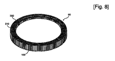
図7及び図8は、本発明に係るウェーハリテーニングリング90を示す図面であって、複数のリテーニング断片100が、略環状を有するベースリング200に付着されている。リテーニング断片100は、CMP工程中にウェーハの側面を支持することによってウェーハの離脱を防止する役割を行い、ベースリング200は、リテーニング断片が付着されている場所であって、図7をひっくり返した図面である図8に示すように、上面にねじ孔210が形成されることによって、ねじを利用してキャリアベース(図示せず)に固定させる。リテーニング断片100の他の役割は、CMP工程中に研磨パッドを所定の圧力で押して、ウェーハエッジの付近で研磨パッドの変形を均一化することである。
図9ないし図11は、本発明に係るリテーニングリングを構成するリテーニング断片の一例を示す斜視図である。まず、図9に示すように、リテーニング断片100は、内側の半径がRiである弧と、外側の半径がRoである弧とによって定義される面を備える。ここで、内側の半径がRiである弧によって定義されるリテーニング断片100の内面は、CMP工程中にウェーハの側面と接触する。したがって、内側半径Riは、研磨されるウェーハの半径より約0.5mmないし2mm大きいことが望ましい。外側半径Roは、内側半径Riより約10mmないし40mm大きくてもよい。リテーニング断片100の厚さtは、約0.5mmないし5mmでありうる。図10は、リテーニング断片102の他の例を示す図面であって、リテーニング断片102の内面は、前述のように、半径Riである弧によって定義される面からなるが、リテーニング断片102の外面は、弧によって定義されず、図10に示すように、平面(例えば、P1及びP2)から構成されることができる。図11は、リテーニング断片103のさらに他の例を示す図面であって、リテーニング断片103の内面及び外面が弧によって定義されず、それぞれ平面P3及びP4により構成された場合を示している。このように、リテーニング断片103の内面が一つ以上の平面(例えば、P3)から構成されるためには、リテーニングリング(図示せず)の中心Cからリテーニング断片103の両端までの二つの直線(点線で表示される)がなす角度θが、20゜より小さいことが望ましい。言い換えれば、約18個以上のリテーニング断片からリテーニングリングを構成するとき、図11に示すように、リテーニング断片103の内面が一つ以上の平面(例えば、P3)からなることができる。
断片の形状は、従来の技術によるリングの形態に比べて、そのサイズが小さいため加工しやすい。特に、厚さが薄い場合、リング状には製作することが難しく、また、製作後にも破損しやすいが、断片の形態に製作すれば、このような問題点が減少する。リテーニングリングの交換時期が、約500μmの摩耗が起こったときであるので、リテーニングリングを、薄いリテーニング断片及びベースリングから構成して使用した後、摩耗されたリテーニング断片のみを交換すれば、捨てられる部分を減らすことができるようになる。リテーニング断片を薄型にしたときに得られる他の長所は、研磨時にリテーニングリングに加えられる圧力によるサイズの変化が少ないため、耐摩耗性には優れているが、圧縮性が高いので、変形しやすい物質もリテーニング断片として使用することができる。図面を参照して説明すれば、図12に示すように、圧縮性(compressibility)の高い物質からなるリテーニング断片120が、圧力P下では圧力方向及び圧力に垂直の方向に変形されたリテーニング断片120’になるが、リテーニング断片が厚い場合には、圧縮される厚さ及び側面の膨張程度が大きいため、CMP工程時にウェーハのリテーニングに問題を起こす。一方、図13に示すように、リテーニング断片130が薄い場合には、圧力Pにより変形されたリテーニング断片130’の圧縮された厚さ及び側面の膨張程度が小さいため、ウェーハのリテーニングに問題を起こさない。
Hereinafter, a retaining ring according to the present invention will be described in detail with reference to the accompanying drawings. However, embodiments of the present invention are provided to enable those skilled in the art to more fully describe the present invention. Accordingly, the shapes of elements in the drawings are exaggerated to emphasize a clearer description, and elements denoted by the same reference numerals in the drawings indicate the same elements.
7 and 8 are views showing a wafer retaining
9 to 11 are perspective views showing an example of a retaining fragment constituting the retaining ring according to the present invention. First, as shown in FIG. 9, the
The shape of the piece is easy to process because its size is small compared to the ring shape according to the prior art. In particular, when the thickness is small, it is difficult to produce a ring shape, and it is easy to be damaged after the production. However, if it is produced in the form of a fragment, such problems are reduced. Since the replacement time of the retaining ring is when wear of about 500 μm has occurred, if the retaining ring is composed of a thin retaining piece and a base ring, then only the worn retaining piece is replaced. It becomes possible to reduce the part that is thrown away. The other advantage of thinning the retaining piece is that it has excellent wear resistance due to the small size change caused by the pressure applied to the retaining ring during polishing, but it is highly compressible and deforms. Easy materials can also be used as retaining pieces. Referring to the drawings, as shown in FIG. 12, a retaining
リテーニング断片は、耐摩耗性に優れており、化学的に不活性物質であるPPS、PEEK、ポリエステル(polyester)、ポリアミド−イミド(polyamide-imide)またはポリウレタン(polyurethane)などのプラスチックから形成されうる。
リテーニング断片が付着されるベースリングは、耐食性に優れたステンレススチールのような金属、PPSのようなプラスチック、またはアルミナのようなセラミックから形成されることができる。ベースリングは、図7に示すように、一体型であってもよく、図14に示すように、下部ベースリング202と上部ベースリング204とが付着されてベースリング206をなすように、2つ以上のリングが付着されて形成されてもよい。このとき、リテーニング断片100が付着され、かつスラリーと接触する上部ベースリング204は、PPSのようなプラスチックからなり、キャリアベースと連結される下部ベースリング202は、ステンレススチールのような金属からなることが望ましい。以下の図面では、図面の簡略化のために、一体型のベースリングのみを示す。
リテーニング断片をベースリングに付着する方法としては、エポキシ、シリコンまたはパラフィンのような接着剤を使用するが、ベースリングを再使用するためには、摩耗されたリテーニング断片を分離しなければならず、そのためには、高温で溶解または分解可能な接着物質または特定の溶剤に溶解される接着物質を使用することが望ましい。リテーニング断片をベースリングに付着するとき、迅速に断片をベースリングにアラインするために、図15に示すリテーニング断片104の付着面に一つ以上の凸部140や、図16に示すような凹部150を形成する。これに対応するベースリングの構造は、図17及び図18に示すように、リテーニング断片が付着されるベースリング200の付着面に凹部220や凸部230を形成して、リテーニング断片104の凸部140とベースリング200の凹部220とが一致するか、またはリテーニング断片104の凹部150とベースリング200の凸部230とが一致すればアラインさせる。リテーニング断片104及びベースリング200に形成される凹部及び凸部の形状は、円筒形、四角柱形であるか、または図19及び図20に示すように、隆線形の凸部142や溝状の凹部152を有することができる。
図21ないし図23は、ベースリング200に付着されるリテーニング断片106、108、109の数による形状の一例を示す下面図であって、リテーニング断片の数は、リテーニングリング90のサイズ、リテーニング断片106、108、109の厚さ及び材質などによって4個ないし72個にする。リテーニングリング90のサイズが大きくなるほど、すなわち、研磨しようとするウェーハのサイズが大きくなるほど、また、リテーニング断片の厚さが薄くなるほど、リテーニング断片のサイズを縮小させ、その数を増加させることが望ましい。特に、複数(例えば、18個以上)のリテーニング断片からリテーニングリングを構成するとき、図23に示すように、ウェーハと接触するリテーニング断片109の内面を平面にすることができる。全てのリテーニング断片をベースリング200に付着したとき、リテーニング断片106、108、109の間に隙間150を有するようにリテーニング断片のサイズを定めることが望ましいが、これは、リテーニング断片106、108、109をベースリング200から分離するとき、作業を容易にする空間と、リテーニング断片106、108、109が熱膨張により膨張できるスペースを提供するためのものであり、また、CMP工程時にスラリーの流入を促すためのものである。隙間150の幅は、1mmないしは5mmであることが望ましい。リテーニング断片106、108、109の間の隙間150は、図21ないし図23に示すように、リテーニングリング90の中心に向ってもよく、図24に示すように、非対称型のリテーニング断片110を付着すれば、隙間160は、リテーニングリング90の中心から離れた所に向うことができる。
図25は、ベースリング250の付着面に形成された溝260を示す図面である。リテーニング断片が薄い場合、リテーニング断片が、平坦なベースリングの付着面に付着されれば、リテーニング断片の間に形成される隙間の深さも浅くなり、これにより、CMP工程時にスラリーが内部に十分に供給されないこともある。これを改善するために、図25に示すように、まず、ベースリング250の付着面に溝260を形成し、図26に示すように、リテーニング断片100を付着すれば、リテーニング断片100の間の隙間270の深さは、リテーニング断片100の厚さより深くなる。
一方、本発明は、前述の実施形態に限定されるものではなく、本発明の思想を逸脱しない範囲内で多様な変化及び変形が可能である。
The retaining piece is excellent in abrasion resistance and may be formed from a chemically inert material such as PPS, PEEK, polyester, polyamide-imide, or polyurethane.
The base ring to which the retaining piece is attached can be formed of a metal such as stainless steel having excellent corrosion resistance, a plastic such as PPS, or a ceramic such as alumina. The base ring may be integrated as shown in FIG. 7, and as shown in FIG. 14, the two base rings 202 and the
The method of attaching the retaining piece to the base ring uses an adhesive such as epoxy, silicone or paraffin, but in order to reuse the base ring, the worn retaining piece must be separated, For this purpose, it is desirable to use an adhesive substance that can be dissolved or decomposed at a high temperature or an adhesive substance that is dissolved in a specific solvent. When attaching the retaining piece to the base ring, in order to quickly align the piece to the base ring, one or
FIGS. 21 to 23 are bottom views showing an example of the shape depending on the number of retaining
FIG. 25 is a view showing a groove 260 formed on the attachment surface of the
On the other hand, the present invention is not limited to the above-described embodiments, and various changes and modifications can be made without departing from the spirit of the present invention.
以上で説明したように、本発明を実施することにより、リテーニングリングの再使用時に交換、廃棄される部分を断片から形成して、加工性を向上させ、また、交換される部分の厚さを縮小させることにより、製造コストを低減させ、環境汚染を防止することができる。また、リテーニングリングにおいて、研磨パッドと接触する部分を断片から構成することにより、多様な素材をリテーニングリングの製作に利用することができる。 As described above, by carrying out the present invention, the part to be replaced and discarded when the retaining ring is reused is formed from fragments, improving the workability, and the thickness of the part to be replaced By reducing the size, manufacturing costs can be reduced and environmental pollution can be prevented. Further, in the retaining ring, a portion that comes into contact with the polishing pad is formed of fragments, so that various materials can be used for manufacturing the retaining ring.
Claims (14)
ウェーハの側面を支持して、化学機械研磨工程中に前記ウェーハの離脱を防止する複数のリテーニング断片と、
前記複数のリテーニング断片が付着し略環状を有するベースリングと、を備えるウェーハリテーニングリング。 A retaining ring for a chemical mechanical polishing apparatus,
A plurality of retaining pieces that support the side of the wafer and prevent the wafer from being detached during the chemical mechanical polishing process;
And a base ring having a substantially annular shape to which the plurality of retaining pieces are attached.
Applications Claiming Priority (3)
| Application Number | Priority Date | Filing Date | Title |
|---|---|---|---|
| KR20040069808 | 2004-09-02 | ||
| KR1020050021248A KR100628736B1 (en) | 2004-09-02 | 2005-03-15 | Retaining ring for chemical mechanical polishing |
| PCT/KR2005/001632 WO2006025641A1 (en) | 2004-09-02 | 2005-05-31 | Retaining ring for chemical mechanical polishing |
Publications (1)
| Publication Number | Publication Date |
|---|---|
| JP2008511983A true JP2008511983A (en) | 2008-04-17 |
Family
ID=36000262
Family Applications (1)
| Application Number | Title | Priority Date | Filing Date |
|---|---|---|---|
| JP2007529663A Pending JP2008511983A (en) | 2004-09-02 | 2005-05-31 | Retaining ring for chemical mechanical polishing |
Country Status (3)
| Country | Link |
|---|---|
| JP (1) | JP2008511983A (en) |
| TW (1) | TWI279288B (en) |
| WO (1) | WO2006025641A1 (en) |
Cited By (5)
| Publication number | Priority date | Publication date | Assignee | Title |
|---|---|---|---|---|
| JP2008147646A (en) * | 2006-11-22 | 2008-06-26 | Applied Materials Inc | Carrier head with retaining ring and carrier ring |
| JP2014511769A (en) * | 2011-03-21 | 2014-05-19 | ローレンス リバモア ナショナル セキュリティー, エルエルシー | Convergent polishing method and convergent polishing system |
| JP2016092370A (en) * | 2014-11-11 | 2016-05-23 | 株式会社荏原製作所 | Polishing equipment |
| JP2017514310A (en) * | 2014-04-22 | 2017-06-01 | アプライド マテリアルズ インコーポレイテッドApplied Materials,Incorporated | Retaining ring with faceted inner surface |
| US12048981B2 (en) | 2015-05-29 | 2024-07-30 | Applied Materials, Inc. | Retaining ring having inner surfaces with features |
Families Citing this family (4)
| Publication number | Priority date | Publication date | Assignee | Title |
|---|---|---|---|---|
| US7575504B2 (en) * | 2006-11-22 | 2009-08-18 | Applied Materials, Inc. | Retaining ring, flexible membrane for applying load to a retaining ring, and retaining ring assembly |
| US7727055B2 (en) | 2006-11-22 | 2010-06-01 | Applied Materials, Inc. | Flexible membrane for carrier head |
| KR102014492B1 (en) * | 2011-09-12 | 2019-08-26 | 어플라이드 머티어리얼스, 인코포레이티드 | Carrier head with composite plastic portions |
| US8998676B2 (en) * | 2012-10-26 | 2015-04-07 | Applied Materials, Inc. | Retaining ring with selected stiffness and thickness |
Family Cites Families (5)
| Publication number | Priority date | Publication date | Assignee | Title |
|---|---|---|---|---|
| KR20010055213A (en) * | 1999-12-10 | 2001-07-04 | 윤종용 | Retainer ring for chemical mechanical polishing machine |
| KR20010104015A (en) * | 2000-05-12 | 2001-11-24 | 윤종용 | Retainer ring in chemical mechanical polishing apparatus |
| US6471566B1 (en) * | 2000-09-18 | 2002-10-29 | Lam Research Corporation | Sacrificial retaining ring CMP system and methods for implementing the same |
| JP2002355753A (en) * | 2001-05-30 | 2002-12-10 | Sumitomo Osaka Cement Co Ltd | Retainer ring of high performance and long life, and polishing device comprising the same |
| KR100424667B1 (en) * | 2001-06-21 | 2004-03-25 | 이부락 | The grind equipment and method manufacture ceramic pad retaining ring of grind for wafer |
-
2005
- 2005-05-31 WO PCT/KR2005/001632 patent/WO2006025641A1/en not_active Ceased
- 2005-05-31 JP JP2007529663A patent/JP2008511983A/en active Pending
- 2005-06-16 TW TW94120084A patent/TWI279288B/en not_active IP Right Cessation
Cited By (8)
| Publication number | Priority date | Publication date | Assignee | Title |
|---|---|---|---|---|
| JP2008147646A (en) * | 2006-11-22 | 2008-06-26 | Applied Materials Inc | Carrier head with retaining ring and carrier ring |
| JP2014511769A (en) * | 2011-03-21 | 2014-05-19 | ローレンス リバモア ナショナル セキュリティー, エルエルシー | Convergent polishing method and convergent polishing system |
| JP2017514310A (en) * | 2014-04-22 | 2017-06-01 | アプライド マテリアルズ インコーポレイテッドApplied Materials,Incorporated | Retaining ring with faceted inner surface |
| US11682561B2 (en) | 2014-04-22 | 2023-06-20 | Applied Materials, Inc. | Retaining ring having inner surfaces with facets |
| US12033865B2 (en) | 2014-04-22 | 2024-07-09 | Applied Materials, Inc. | Retaining ring having inner surfaces with facets |
| JP2016092370A (en) * | 2014-11-11 | 2016-05-23 | 株式会社荏原製作所 | Polishing equipment |
| US12048981B2 (en) | 2015-05-29 | 2024-07-30 | Applied Materials, Inc. | Retaining ring having inner surfaces with features |
| US12434348B2 (en) | 2015-05-29 | 2025-10-07 | Applied Materials, Inc. | Retaining ring having inner surfaces with features |
Also Published As
| Publication number | Publication date |
|---|---|
| WO2006025641A1 (en) | 2006-03-09 |
| TWI279288B (en) | 2007-04-21 |
| TW200609078A (en) | 2006-03-16 |
Similar Documents
| Publication | Publication Date | Title |
|---|---|---|
| KR101401012B1 (en) | Stepped retaining ring | |
| US6068548A (en) | Mechanically stabilized retaining ring for chemical mechanical polishing | |
| EP2180977B1 (en) | Retaining ring with shaped profile | |
| US7503837B2 (en) | Composite retaining ring | |
| US7101272B2 (en) | Carrier head for thermal drift compensation | |
| JP2009283885A (en) | Retainer ring | |
| KR20050067147A (en) | Retaining ring for holding semiconductor wafers in a chemical-mechanical polishing device | |
| JP2008511983A (en) | Retaining ring for chemical mechanical polishing | |
| JP2005034959A (en) | Polishing device and retainer ring | |
| KR100628736B1 (en) | Retaining ring for chemical mechanical polishing | |
| WO2009048234A2 (en) | Retainer ring of cmp machine | |
| KR102865675B1 (en) | Retainer ring | |
| KR200387804Y1 (en) | Retaining ring for chemical mechanical polishing | |
| KR20070027897A (en) | Retaining ring for chemical mechanical polishing | |
| KR101043487B1 (en) | Polishing Pad Compensation Device and Method for Wafer Double-Sided Polishing Machine | |
| KR20060117148A (en) | Retaining ring for chemical mechanical polishing and its manufacturing method | |
| CN216967413U (en) | Retainer ring and substrate grinding device comprising same | |
| US6921324B1 (en) | Pad backer | |
| KR20030012646A (en) | Polishing head of a chemical mechanical polishing machine | |
| KR20210002854A (en) | Retainer ring | |
| KR20120108269A (en) | Head assembly and retainer ring for water grinding apparatus | |
| KR102727514B1 (en) | Retainer ring and substrate polishing appratus comprising the same | |
| JP2007296603A (en) | Retainer ring processing apparatus | |
| KR20010104015A (en) | Retainer ring in chemical mechanical polishing apparatus | |
| KR20220062809A (en) | Retainer ring and substrate polishing appratus comprising the same |