JP2008507384A - Method for manufacturing absorbent core structure - Google Patents
Method for manufacturing absorbent core structure Download PDFInfo
- Publication number
- JP2008507384A JP2008507384A JP2007523817A JP2007523817A JP2008507384A JP 2008507384 A JP2008507384 A JP 2008507384A JP 2007523817 A JP2007523817 A JP 2007523817A JP 2007523817 A JP2007523817 A JP 2007523817A JP 2008507384 A JP2008507384 A JP 2008507384A
- Authority
- JP
- Japan
- Prior art keywords
- carrier
- sandwich structure
- carrier material
- support
- manufacturing
- Prior art date
- Legal status (The legal status is an assumption and is not a legal conclusion. Google has not performed a legal analysis and makes no representation as to the accuracy of the status listed.)
- Granted
Links
Images


Classifications
-
- A—HUMAN NECESSITIES
- A61—MEDICAL OR VETERINARY SCIENCE; HYGIENE
- A61F—FILTERS IMPLANTABLE INTO BLOOD VESSELS; PROSTHESES; DEVICES PROVIDING PATENCY TO, OR PREVENTING COLLAPSING OF, TUBULAR STRUCTURES OF THE BODY, e.g. STENTS; ORTHOPAEDIC, NURSING OR CONTRACEPTIVE DEVICES; FOMENTATION; TREATMENT OR PROTECTION OF EYES OR EARS; BANDAGES, DRESSINGS OR ABSORBENT PADS; FIRST-AID KITS
- A61F13/00—Bandages or dressings; Absorbent pads
- A61F13/15—Absorbent pads, e.g. sanitary towels, swabs or tampons for external or internal application to the body; Supporting or fastening means therefor; Tampon applicators
- A61F13/15577—Apparatus or processes for manufacturing
- A61F13/15617—Making absorbent pads from fibres or pulverulent material with or without treatment of the fibres
- A61F13/15658—Forming continuous, e.g. composite, fibrous webs, e.g. involving the application of pulverulent material on parts thereof
-
- A—HUMAN NECESSITIES
- A61—MEDICAL OR VETERINARY SCIENCE; HYGIENE
- A61F—FILTERS IMPLANTABLE INTO BLOOD VESSELS; PROSTHESES; DEVICES PROVIDING PATENCY TO, OR PREVENTING COLLAPSING OF, TUBULAR STRUCTURES OF THE BODY, e.g. STENTS; ORTHOPAEDIC, NURSING OR CONTRACEPTIVE DEVICES; FOMENTATION; TREATMENT OR PROTECTION OF EYES OR EARS; BANDAGES, DRESSINGS OR ABSORBENT PADS; FIRST-AID KITS
- A61F13/00—Bandages or dressings; Absorbent pads
- A61F13/15—Absorbent pads, e.g. sanitary towels, swabs or tampons for external or internal application to the body; Supporting or fastening means therefor; Tampon applicators
- A61F13/15577—Apparatus or processes for manufacturing
- A61F13/15764—Transferring, feeding or handling devices; Drives
-
- A—HUMAN NECESSITIES
- A61—MEDICAL OR VETERINARY SCIENCE; HYGIENE
- A61F—FILTERS IMPLANTABLE INTO BLOOD VESSELS; PROSTHESES; DEVICES PROVIDING PATENCY TO, OR PREVENTING COLLAPSING OF, TUBULAR STRUCTURES OF THE BODY, e.g. STENTS; ORTHOPAEDIC, NURSING OR CONTRACEPTIVE DEVICES; FOMENTATION; TREATMENT OR PROTECTION OF EYES OR EARS; BANDAGES, DRESSINGS OR ABSORBENT PADS; FIRST-AID KITS
- A61F13/00—Bandages or dressings; Absorbent pads
- A61F13/15—Absorbent pads, e.g. sanitary towels, swabs or tampons for external or internal application to the body; Supporting or fastening means therefor; Tampon applicators
- A61F13/15577—Apparatus or processes for manufacturing
- A61F13/15804—Plant, e.g. involving several steps
-
- A—HUMAN NECESSITIES
- A61—MEDICAL OR VETERINARY SCIENCE; HYGIENE
- A61F—FILTERS IMPLANTABLE INTO BLOOD VESSELS; PROSTHESES; DEVICES PROVIDING PATENCY TO, OR PREVENTING COLLAPSING OF, TUBULAR STRUCTURES OF THE BODY, e.g. STENTS; ORTHOPAEDIC, NURSING OR CONTRACEPTIVE DEVICES; FOMENTATION; TREATMENT OR PROTECTION OF EYES OR EARS; BANDAGES, DRESSINGS OR ABSORBENT PADS; FIRST-AID KITS
- A61F13/00—Bandages or dressings; Absorbent pads
- A61F13/15—Absorbent pads, e.g. sanitary towels, swabs or tampons for external or internal application to the body; Supporting or fastening means therefor; Tampon applicators
- A61F13/53—Absorbent pads, e.g. sanitary towels, swabs or tampons for external or internal application to the body; Supporting or fastening means therefor; Tampon applicators characterised by the absorbing medium
- A61F13/531—Absorbent pads, e.g. sanitary towels, swabs or tampons for external or internal application to the body; Supporting or fastening means therefor; Tampon applicators characterised by the absorbing medium having a homogeneous composition through the thickness of the pad
- A61F13/532—Absorbent pads, e.g. sanitary towels, swabs or tampons for external or internal application to the body; Supporting or fastening means therefor; Tampon applicators characterised by the absorbing medium having a homogeneous composition through the thickness of the pad inhomogeneous in the plane of the pad
- A61F13/5323—Absorbent pads, e.g. sanitary towels, swabs or tampons for external or internal application to the body; Supporting or fastening means therefor; Tampon applicators characterised by the absorbing medium having a homogeneous composition through the thickness of the pad inhomogeneous in the plane of the pad having absorbent material located in discrete regions, e.g. pockets
-
- B—PERFORMING OPERATIONS; TRANSPORTING
- B05—SPRAYING OR ATOMISING IN GENERAL; APPLYING FLUENT MATERIALS TO SURFACES, IN GENERAL
- B05C—APPARATUS FOR APPLYING FLUENT MATERIALS TO SURFACES, IN GENERAL
- B05C1/00—Apparatus in which liquid or other fluent material is applied to the surface of the work by contact with a member carrying the liquid or other fluent material, e.g. a porous member loaded with a liquid to be applied as a coating
- B05C1/04—Apparatus in which liquid or other fluent material is applied to the surface of the work by contact with a member carrying the liquid or other fluent material, e.g. a porous member loaded with a liquid to be applied as a coating for applying liquid or other fluent material to work of indefinite length
- B05C1/08—Apparatus in which liquid or other fluent material is applied to the surface of the work by contact with a member carrying the liquid or other fluent material, e.g. a porous member loaded with a liquid to be applied as a coating for applying liquid or other fluent material to work of indefinite length using a roller or other rotating member which contacts the work along a generating line
- B05C1/0804—Apparatus in which liquid or other fluent material is applied to the surface of the work by contact with a member carrying the liquid or other fluent material, e.g. a porous member loaded with a liquid to be applied as a coating for applying liquid or other fluent material to work of indefinite length using a roller or other rotating member which contacts the work along a generating line the material being applied without contact with the roller
-
- B—PERFORMING OPERATIONS; TRANSPORTING
- B05—SPRAYING OR ATOMISING IN GENERAL; APPLYING FLUENT MATERIALS TO SURFACES, IN GENERAL
- B05C—APPARATUS FOR APPLYING FLUENT MATERIALS TO SURFACES, IN GENERAL
- B05C1/00—Apparatus in which liquid or other fluent material is applied to the surface of the work by contact with a member carrying the liquid or other fluent material, e.g. a porous member loaded with a liquid to be applied as a coating
- B05C1/04—Apparatus in which liquid or other fluent material is applied to the surface of the work by contact with a member carrying the liquid or other fluent material, e.g. a porous member loaded with a liquid to be applied as a coating for applying liquid or other fluent material to work of indefinite length
- B05C1/08—Apparatus in which liquid or other fluent material is applied to the surface of the work by contact with a member carrying the liquid or other fluent material, e.g. a porous member loaded with a liquid to be applied as a coating for applying liquid or other fluent material to work of indefinite length using a roller or other rotating member which contacts the work along a generating line
- B05C1/0808—Details thereof, e.g. surface characteristics
-
- B—PERFORMING OPERATIONS; TRANSPORTING
- B05—SPRAYING OR ATOMISING IN GENERAL; APPLYING FLUENT MATERIALS TO SURFACES, IN GENERAL
- B05C—APPARATUS FOR APPLYING FLUENT MATERIALS TO SURFACES, IN GENERAL
- B05C1/00—Apparatus in which liquid or other fluent material is applied to the surface of the work by contact with a member carrying the liquid or other fluent material, e.g. a porous member loaded with a liquid to be applied as a coating
- B05C1/04—Apparatus in which liquid or other fluent material is applied to the surface of the work by contact with a member carrying the liquid or other fluent material, e.g. a porous member loaded with a liquid to be applied as a coating for applying liquid or other fluent material to work of indefinite length
- B05C1/08—Apparatus in which liquid or other fluent material is applied to the surface of the work by contact with a member carrying the liquid or other fluent material, e.g. a porous member loaded with a liquid to be applied as a coating for applying liquid or other fluent material to work of indefinite length using a roller or other rotating member which contacts the work along a generating line
- B05C1/0817—Apparatus in which liquid or other fluent material is applied to the surface of the work by contact with a member carrying the liquid or other fluent material, e.g. a porous member loaded with a liquid to be applied as a coating for applying liquid or other fluent material to work of indefinite length using a roller or other rotating member which contacts the work along a generating line characterised by means for removing partially liquid or other fluent material from the roller, e.g. scrapers
-
- B—PERFORMING OPERATIONS; TRANSPORTING
- B05—SPRAYING OR ATOMISING IN GENERAL; APPLYING FLUENT MATERIALS TO SURFACES, IN GENERAL
- B05C—APPARATUS FOR APPLYING FLUENT MATERIALS TO SURFACES, IN GENERAL
- B05C19/00—Apparatus specially adapted for applying particulate materials to surfaces
- B05C19/04—Apparatus specially adapted for applying particulate materials to surfaces the particulate material being projected, poured or allowed to flow onto the surface of the work
-
- B—PERFORMING OPERATIONS; TRANSPORTING
- B05—SPRAYING OR ATOMISING IN GENERAL; APPLYING FLUENT MATERIALS TO SURFACES, IN GENERAL
- B05C—APPARATUS FOR APPLYING FLUENT MATERIALS TO SURFACES, IN GENERAL
- B05C11/00—Component parts, details or accessories not specifically provided for in groups B05C1/00 - B05C9/00
- B05C11/10—Storage, supply or control of liquid or other fluent material; Recovery of excess liquid or other fluent material
- B05C11/1039—Recovery of excess liquid or other fluent material; Controlling means therefor
-
- Y—GENERAL TAGGING OF NEW TECHNOLOGICAL DEVELOPMENTS; GENERAL TAGGING OF CROSS-SECTIONAL TECHNOLOGIES SPANNING OVER SEVERAL SECTIONS OF THE IPC; TECHNICAL SUBJECTS COVERED BY FORMER USPC CROSS-REFERENCE ART COLLECTIONS [XRACs] AND DIGESTS
- Y10—TECHNICAL SUBJECTS COVERED BY FORMER USPC
- Y10T—TECHNICAL SUBJECTS COVERED BY FORMER US CLASSIFICATION
- Y10T156/00—Adhesive bonding and miscellaneous chemical manufacture
- Y10T156/10—Methods of surface bonding and/or assembly therefor
- Y10T156/1002—Methods of surface bonding and/or assembly therefor with permanent bending or reshaping or surface deformation of self sustaining lamina
- Y10T156/1007—Running or continuous length work
- Y10T156/1023—Surface deformation only [e.g., embossing]
-
- Y—GENERAL TAGGING OF NEW TECHNOLOGICAL DEVELOPMENTS; GENERAL TAGGING OF CROSS-SECTIONAL TECHNOLOGIES SPANNING OVER SEVERAL SECTIONS OF THE IPC; TECHNICAL SUBJECTS COVERED BY FORMER USPC CROSS-REFERENCE ART COLLECTIONS [XRACs] AND DIGESTS
- Y10—TECHNICAL SUBJECTS COVERED BY FORMER USPC
- Y10T—TECHNICAL SUBJECTS COVERED BY FORMER US CLASSIFICATION
- Y10T156/00—Adhesive bonding and miscellaneous chemical manufacture
- Y10T156/10—Methods of surface bonding and/or assembly therefor
- Y10T156/1002—Methods of surface bonding and/or assembly therefor with permanent bending or reshaping or surface deformation of self sustaining lamina
- Y10T156/1025—Methods of surface bonding and/or assembly therefor with permanent bending or reshaping or surface deformation of self sustaining lamina to form undulated to corrugated sheet and securing to base with parts of shaped areas out of contact
Landscapes
- Health & Medical Sciences (AREA)
- Engineering & Computer Science (AREA)
- Life Sciences & Earth Sciences (AREA)
- General Health & Medical Sciences (AREA)
- Heart & Thoracic Surgery (AREA)
- Vascular Medicine (AREA)
- Biomedical Technology (AREA)
- Animal Behavior & Ethology (AREA)
- Epidemiology (AREA)
- Public Health (AREA)
- Veterinary Medicine (AREA)
- Manufacturing & Machinery (AREA)
- Botany (AREA)
- Absorbent Articles And Supports Therefor (AREA)
- Orthopedics, Nursing, And Contraception (AREA)
- Laminated Bodies (AREA)
Abstract
本発明は、キャリア材とカバー材の間に挟み込まれた粒子状物質のパターンを備えたサンドイッチ構造体を形成させる方法に関するものである。前記方法によって、所定のパターンを高生産速度で正確に形成できるようになる。前記方法は、乳幼児用おむつなどの使い捨て吸収性物品の製造にとりわけ有用である。 The present invention relates to a method of forming a sandwich structure having a particulate matter pattern sandwiched between a carrier material and a cover material. By the above method, a predetermined pattern can be accurately formed at a high production rate. The method is particularly useful for the manufacture of disposable absorbent articles such as baby diapers.
Description
本発明は、キャリア材及びカバー材の間に挟み込まれた粒子状物質パターンを備えたサンドイッチ構造体を形成させる方法に関するものである。ある特定の実施形態では、前記粒子状物質は超吸収体であり、サンドイッチ構造体は、使い捨て吸収製品で使われる液体吸収性構造体である。 The present invention relates to a method of forming a sandwich structure having a particulate matter pattern sandwiched between a carrier material and a cover material. In one particular embodiment, the particulate material is a superabsorbent and the sandwich structure is a liquid absorbent structure used in disposable absorbent products.
ある特定のパターンによって粒子状物質が含まれている複合構造体は当該技術分野においてよく知られており、例えば欧州特許第1,447,066号(Busamら、P&G)には吸収性物品用の吸収性コアが開示されているが、このコアには、濡れると不動化する粒子状吸収物質が含まれている。前記吸収性コアには、吸収性ポリマー物質のような吸収性物質を備えた基質層が1つ備わっている。 Composite structures containing particulate matter in a particular pattern are well known in the art, for example in EP 1,447,066 (Busam et al., P & G) for absorbent articles. An absorbent core is disclosed that includes a particulate absorbent material that is immobilized when wet. The absorbent core has one substrate layer comprising an absorbent material such as an absorbent polymer material.
また、米国特許第4,381,783号(Elias)には、吸収性ヒドロコロイド物質のポケットが備わっているコアを持つ吸収性物品が開示されている。前記ポケットは、吸収性ポリマー材の動き、特に前記物品の全体又は一部に尿がしみ込んだ時の動きを制限するために配置されているものである。前記ポケットは吸収層の一部を成しており、典型的にはセルロース物質から形成されている。つまり、前記特許の指示内容に従って吸収性ポリマー物質を十分に不動化させるには、比較的大量のセルロース物質が必要になる。更には、前記ポケットを配置すると、コアの高吸収性区域、例えば吸収性ポリマー物質の区域に液体が無制限に流入するのを防げる可能性がある。 U.S. Pat. No. 4,381,783 (Elias) also discloses an absorbent article having a core with a pocket of absorbent hydrocolloid material. The pockets are arranged to limit the movement of the absorbent polymer material, particularly when urine has soaked into all or part of the article. The pocket forms part of the absorbent layer and is typically formed from a cellulosic material. That is, a relatively large amount of cellulose material is required to sufficiently immobilize the absorbent polymer material in accordance with the contents of the patent. Furthermore, the placement of the pockets may prevent unlimited flow of liquid into the superabsorbent area of the core, for example the area of absorbent polymer material.
つまり、粒子状吸収性ポリマー物質(吸収性ゲル化物質又は超吸体と呼ばれることも多い)などの吸収性物質を不均等に配置させた吸収性物品を作る方法もよく知られている。PCT国際公開特許WO03/101622A2号(Tombultら、P&G)では、不連続的な粒子配置を可能にするパルス法について開示されており、また、米国特許5,213,817号(Pelley、McNeillPPC)でも同様の構造体が製造できる。 That is, a method of making an absorbent article in which absorbent materials such as particulate absorbent polymer materials (also often called absorbent gelling materials or superabsorbents) are arranged unevenly is well known. PCT International Publication No. WO 03/101622 A2 (Tombult et al., P & G) discloses a pulsing method that enables discontinuous particle placement, and also in US Pat. No. 5,213,817 (Pelley, McNeill PPC). Similar structures can be manufactured.
ウェブ上に粒子状吸収性物質パターンを配置するための方法については、回転マスクを用いるものが米国特許第4,800,102号(Takada、Nordson)に記載されており、PTC国際公開特許WO92/019198A号(Perneborn/Molnlycke)には直線的に動くマスクが開示されている。仏国特許公開第2,583,377号(Piron、Colgate Palmolive)では、コンベヤーベルトのキャリア上に不連続的なパターンを形成させるためにホッパーから投与される吸収性粉末を入れる計量ドラムが開示されている。前記ドラムは段階的な動きで操作される。 US Pat. No. 4,800,102 (Takada, Nordson) describes a method for placing a particulate absorbent material pattern on a web using a rotating mask. No. 019198A (Perneborn / Mornlycke) discloses a linearly moving mask. French Patent Publication No. 2,583,377 (Piron, Colgate Palmolive) discloses a metering drum containing absorbent powder dispensed from a hopper to form a discontinuous pattern on a carrier of a conveyor belt. ing. The drum is operated in a stepwise manner.
米国特許第5,494,622号(Heathら、K−C)では、所望のパターンで粒子のポケットを高速で移動するウェブ上に形成させることに照準が定められている。パターンチャンバーには高吸収性物質の粒子が搭載されており、前記物質を通じて、開口部パターンを備えた表面上に気体透過性ウェブを運んで、前記開口部を通じて真空状態を実現して、前記表面の開口部パターンのウェブ上に前記粒子が沈着するようにする。前記粒子が沈着した前記ウェブは液体透過性物質で覆うか、前記透過性ウェブにさまざまな大きさの張力を加えてウェブの多孔性を変化させる。前記粒子は所望のポケットパターンでウェブ上に固定し、各ポケット間にある余剰粒子は除去する。このようにして形成させたポケットは「島」のように、その周囲はすべて接合領域に囲まれている。 In US Pat. No. 5,494,622 (Heath et al., K-C), the aim is to form a pocket of particles in a desired pattern on a fast moving web. The pattern chamber is loaded with particles of a superabsorbent material, carrying a gas permeable web through the material onto a surface with an opening pattern to achieve a vacuum through the opening, and the surface. The particles are deposited on the web of the opening pattern. The web on which the particles have been deposited is covered with a liquid permeable material or various sized tensions are applied to the permeable web to change the porosity of the web. The particles are fixed on the web in a desired pocket pattern, and excess particles between each pocket are removed. The pockets formed in this way are all surrounded by a junction region like an “island”.
上記特許には、表面又は可動基質上に粒子状物質を配置する方法についてのさまざまなアプローチが記載されているが、現在でも、極めて明確なパターンで粒子サンドイッチを高い生産速度で製造する方法に対するニーズが存在している。 Although the above patents describe various approaches for placing particulate matter on a surface or movable substrate, there is still a need for a method of producing a particle sandwich at a high production rate in a very clear pattern. Is present.
概要
本発明は、極めて明確なパターンでウェブ材の間に挟み込んで粒子状物質を含有させたサンドイッチ構造体を形成させる方法に関するものである。
Overview The present invention relates to a method of forming a sandwich structure containing particulate material sandwiched between web materials in a very clear pattern.
前記方法には、実質的に平坦なキャリア材及び実質的に平坦なカバー材を組み込んで、外側に複数のサンドイッチ層を形成させる工程が含まれている。この場合、単一の素材によって双方のサンドイッチ層を形成させても、複数の素材によって外側のサンドイッチ層を形成させてもよい。次の工程では、支持パターンを備えている前記キャリア材に、実質的に無端の支持手段を取り付け、続いてキャリア材保持手段を取り付ける。前記キャリア材は、固定フレームを基準としたキャリア速度で前記支持手段を覆うように配置することによって、前記キャリア材を前記支持パターンの支持面に接触させるようにして、キャリア材と前記キャリア支持手段の接触面との相対速度を実質的に0にする。粒子状物質を投入し、続いて前記物質の量を事前に計測する。前記カバー材と前記キャリア材を接合させて、固定手段によってこれら2つの間に粒子状物質を配置する。前記キャリア材は、支持装置の支持パターン領域のみで支え、前記キャリア保持手段によって前記キャリア材を変形させ、非支持領域にくぼみが形成されるようにする。前記粒子状物質を前記キャリア材まで移動させて前記くぼみの中に投入することによって、粒子状物質の第1のパターンを形成させる。 The method includes incorporating a substantially flat carrier material and a substantially flat cover material to form a plurality of sandwich layers on the outside. In this case, both sandwich layers may be formed of a single material, or the outer sandwich layer may be formed of a plurality of materials. In the next step, a substantially endless support means is attached to the carrier material having a support pattern, followed by attachment of the carrier material holding means. The carrier material is disposed so as to cover the support means at a carrier speed based on a fixed frame, so that the carrier material is brought into contact with the support surface of the support pattern, and the carrier material and the carrier support means The relative speed with respect to the contact surface is substantially zero. Particulate matter is charged and subsequently the amount of said material is measured in advance. The cover material and the carrier material are joined, and a particulate substance is disposed between the two by a fixing means. The carrier material is supported only by the support pattern region of the support device, and the carrier material is deformed by the carrier holding means so that a recess is formed in the non-support region. A first pattern of particulate matter is formed by moving the particulate matter to the carrier material and throwing it into the recess.
ある好ましい手法では、前記キャリア材は不織材料、好ましくはSMSタイプ又はSMMSタイプであり、また前記キャリア材の横伸び率又は縦伸び率が20%を超えており、好ましくは100%を超えて伸長し、更に好ましくは前記伸び率が200%以下である。前記キャリア材の縦方向の伸び率の横方向の伸び率に対する比率は、所定の荷重下において1対2以下である。また、前記カバー材も不織材料にすることができ、所望によりキャリア材と同じ素材にできる。 In one preferred approach, the carrier material is a non-woven material, preferably an SMS or SMMS type, and the carrier material has a lateral or longitudinal elongation of greater than 20%, preferably greater than 100%. It extends | stretches, More preferably, the said elongation rate is 200% or less. The ratio of the longitudinal elongation rate of the carrier material to the lateral elongation rate is 1 to 2 or less under a predetermined load. The cover material can also be a non-woven material, and can be the same material as the carrier material if desired.
前記粒子状物質はバルク材、好ましくは超吸収体、更に好ましくは部分架橋ポリアクリレート材にすることができる。 The particulate material can be a bulk material, preferably a superabsorbent, more preferably a partially crosslinked polyacrylate material.
ある好ましい手法では、前記キャリア支持手段は回転ドラム、好ましくは外側に円筒シェルを備えた回転ドラムである。前記キャリア保持手段が減圧吸気であれば更に好ましい。 In one preferred approach, the carrier support means is a rotating drum, preferably a rotating drum with an outer cylindrical shell. More preferably, the carrier holding means is a reduced pressure intake.
前記キャリア支持パターンは支持ピンから構成させてもよく、その場合、隣り合う前記キャリア支持ピンの間隔は5mm超、30mm以下にしてよい。前記支持ピンには、面積が少なくとも0.8mm2、好ましくは少なくとも4mm2、かつ170mm2以下、好ましくは80mm2以下の外面がある。 The carrier support pattern may be composed of support pins, in which case the distance between adjacent carrier support pins may be greater than 5 mm and not greater than 30 mm. The support pin has an outer surface with an area of at least 0.8 mm 2 , preferably at least 4 mm 2 and no more than 170 mm 2 , preferably no more than 80 mm 2 .
前記サンドイッチ固定手段は好ましくは熱接合又は接着接合、更に好ましくは噴霧接着剤である。前記接合領域の面積はパターン区域の少なくとも2%、好ましくは少なくとも7%、かつ、更に好ましくは50%以下である。前記接合領域に粒子が存在していないことを判断するための方法によって、前記接合領域に粒子状物質が実質的に含まれていないことが確認されているのが好ましい。 Said sandwich fixing means is preferably thermal bonding or adhesive bonding, more preferably spray adhesive. The area of the bonding region is at least 2% of the pattern area, preferably at least 7%, and more preferably 50% or less. It is preferable that it is confirmed that the particulate matter is not substantially contained in the joining region by a method for judging that particles are not present in the joining region.
前記キャリア保持手段によって前記キャリア材を伸長させ、前記キャリア材が原初の平面状から変形してくぼみが形成されるようにする。前記くぼみの体積は30mm3超、好ましくは100mm3超、かつ約1,000mm3未満であるのが好ましい。前記粒子状物質の投入量は前記くぼみの体積の5%超かつ150%以下であるのが好ましい。
The carrier material is elongated by the carrier holding means so that the carrier material is deformed from the original flat shape to form a recess. It said recess of
本発明は、極めて明確な量とパターンで支持材料間に挟み込まれた粒子状物質を含有するサンドイッチ構造体を製造させることに照準を定めたものである。このような構造体は使い捨て吸収性物品用として特に有用である。前記物品では、使用目的によって求められる吸収力が異なり、さまざまなニーズがある。 The present invention is aimed at producing a sandwich structure containing particulate matter sandwiched between support materials in a very well defined amount and pattern. Such a structure is particularly useful for disposable absorbent articles. The articles have different needs depending on the purpose of use, and have various needs.
本明細書で使用する時、以下の用語は以下の意味を有する。 As used herein, the following terms have the following meanings.
「吸収性物品」とは、液体を吸収及び収容する装置を指し、より具体的には、着用者の身体に接触又は近接するように配置して、身体から排泄された様々な排出物を吸収及び収容する装置を指す。吸収性物品としては、おむつ、成人失禁用ブリーフ、トレーニングパンツ、おむつホルダー及びおむつライナー、生理用ナプキン等が挙げられるが、これらに限定されない。 An “absorbent article” refers to a device that absorbs and contains liquid, and more specifically, it is placed in contact with or close to the wearer's body to absorb various excretions excreted from the body. And the device that houses it. Absorbent articles include, but are not limited to, diapers, adult incontinence briefs, training pants, diaper holders and diaper liners, sanitary napkins, and the like.
「おむつ」とは一般的に、乳幼児及び失禁症者が胴体下部の周りに着用する吸収性物品を指す。 “Diaper” generally refers to an absorbent article worn by infants and incontinent persons about the lower torso.
「使い捨て」という用語は、本明細書では、通常洗濯又は他の方法で復元又は再使用することを想定していない(すなわち、1回使用した後に廃棄、好ましくはリサイクル、堆肥化、又は環境に適合する方法で処理することを前提としている)物品を説明するために使用する。 The term “disposable” is not intended herein to be restored or reused, usually in laundry or otherwise (ie, discarded after use, preferably recycled, composted, or into the environment). Used to describe an article that is assumed to be processed in a compatible manner.
「含む」及び「含んでいる」という用語は、その目的語、例えば構成要素の存在を指定する制限のない用語であるが、当技術分野で既知の又は本明細書で開示した他の機構、要素、工程又は構成要素の存在を排除しない言葉である。 The terms “including” and “including” are unrestricted terms that specify their object, eg, the presence of a component, but other mechanisms known in the art or disclosed herein, A word that does not exclude the presence of an element, process or component.
「ウェブ材」という用語は、1方向、すなわち縦方向、あるいは長さ方向又はウェブ材を基準としてデカルト座標のx軸方向に向かって実質的に無端の物質を指す。この用語には、実質的に無端の物質を切断した断片又は別の方法で前記物質から分離させた断片をほぼ無限に配列したものも含まれる。必ずというわけではないが、ウェブ材の厚み(z軸方向の長さ)は縦方向の伸長部(x軸方向の長さ)よりもかなり短い場合が多い。ウェブ材の幅(y方向の長さ)は典型的には、厚みよりもかなり長く、全長よりも短い。必ずというわけではないが、ウェブ材の厚みと幅はウェブの長手方向に沿ってほぼ一定の値をとる。何ら制限を設けるつもりはないが、前記ウェブ材は、セルロース系繊維材、ティッシュ、織布又は不織材料などにしてよい。必ずというわけではないが、ウェブ材は典型的には、ロール状に巻いたり、スプールに巻いたり、折り畳んで箱に入れたりした状態で手に入る。そして、入手した個々のウェブ材をつなぎ合わせて、実質的に無端の構造を作り出してよい。ウェブ材は、多層不織材料、コーティングティッシュ、不織材料/フィルムラミネートといった複数のウェブ構成材から構成させてよい。ウェブ材には、追加の接合剤、粒子、親水化剤といったその他の物質を含有させてもよい。 The term “web material” refers to a material that is substantially endless in one direction, ie, in the longitudinal direction, or in the lengthwise direction or the x-axis direction of Cartesian coordinates relative to the web material. The term also includes fragments obtained by cutting a substantially endless material or otherwise separated from the material by an almost infinite number. Although not necessarily, the thickness (the length in the z-axis direction) of the web material is often considerably shorter than the elongated portion (the length in the x-axis direction). The width of the web material (the length in the y direction) is typically much longer than the thickness and shorter than the total length. Although not necessarily, the thickness and width of the web material take substantially constant values along the longitudinal direction of the web. The web material may be a cellulosic fiber material, tissue, woven fabric, or non-woven material, although no limitation is intended. Although not necessarily, web materials are typically available in rolls, spools, folded and boxed. The obtained individual web materials may then be joined to create a substantially endless structure. The web material may be composed of a plurality of web components such as multilayer nonwoven materials, coated tissues, nonwoven materials / film laminates. The web material may contain other substances such as additional bonding agents, particles, hydrophilizing agents.
「超吸収体」「超吸収材料(SAM)」「吸収性ゲル材料(AGM)」「吸収性ポリマー材料」は、本明細書では同義語として使用するとともに、部分架橋ポリマー材を指し、前記部分架橋ポリマー材は、水を吸収可能で、膨張してゲルを形成するものである。 “Superabsorber” “Superabsorbent material (SAM)” “Absorptive gel material (AGM)” “Absorptive polymer material” are used herein as synonyms and refer to a partially cross-linked polymer material, The crosslinked polymer material is capable of absorbing water and swells to form a gel.
Protect&Gamble Companyに譲渡された特許及び特許出願のうち、本明細書で引用する特許及び特許出願(明細書に記載されている特許も含む)は、本明細書と矛盾しない範囲で本明細書に参考として組み入れる。 Of the patents and patent applications assigned to the Protect & Gamble Company, the patents and patent applications cited in this specification (including the patents described in the specification) are referred to in this specification to the extent that they do not conflict with this specification. Incorporate as
代表的な吸収構造体を図1及び図2に示す。図1は、本発明の吸収性物品の好ましい実施形態であるおむつ20の平面図である。前記おむつは、収縮させずに広げた状態(すなわち弾性によって収縮させていない状態)で示してある。構造体の一部を切り取って、おむつ20の下層構造がより明瞭になるようにしてある。また、おむつ20の着用者と接触する部分が見えるように示してある。図1のおむつ20のシャーシ22は、おむつ20の本体を構成している。シャーシ22には、液体透過性トップシート24及び/又は液体不透過性バックシート26を備えた外側カバーが搭載されている。前記シャーシには、トップシート24とバックシート26の間に挿入させた吸収性コア28の一部が含まれていてもよい。また、前記シャーシには、トップシート24とバックシート26の間に挿入させた吸収性コア28の大部分又は全部が含まれていてもよい。更にシャーシにはサイドパネル30、伸縮性レッグカフ32、伸縮性ウエスト機構34が備わっているのが好ましく、レッグカフ32及び伸縮性ウエスト機構にはそれぞれ伸縮性部材33が含まれているのが典型である。おむつ20の一端は、おむつ20の第1のウエスト領域36を構成している。反対側の端部は、おむつ20の第2のウエスト領域38を構成している。おむつ20の中間部は、第1のウエスト領域36と第2のウエスト領域38の間で長手方向に延びる股部37を構成している。ウエスト領域36及び38には伸縮性成分を含有させて、前記成分が着用者の腰の周りで収縮してフィット感及び密閉力を向上させるようにしてもよい(伸縮性ウエスト機構34参照)。股部37はおむつ20の一部分であり、おむつ20を着用した時に着用者の脚の周辺に来る部分である。おむつ20には長手軸100及び横軸110が描かれている。おむつ20の外周は、おむつ20の外縁部によって形成されており、前記外縁部では長手縁部44がおむつ20の長手軸線100とほぼ平行に走っており、また終縁部46がおむつ20の横軸線110とほぼ平行に、両側の長手縁部44をつなぐように走っている。また、シャーシには締結装置も含まれており、前記装置には締結部材40を1つ以上、ランディング領域42を1つ以上含めてよい。
A typical absorbent structure is shown in FIGS. FIG. 1 is a plan view of a diaper 20 which is a preferred embodiment of the absorbent article of the present invention. The diaper is shown in a state of being expanded without being contracted (that is, not being contracted by elasticity). A part of the structure is cut out so that the lower layer structure of the diaper 20 becomes clearer. Moreover, it has shown so that the part which contacts the wearer of the diaper 20 may be seen. The chassis 22 of the diaper 20 in FIG. 1 constitutes the main body of the diaper 20. The chassis 22 is mounted with an outer cover including a liquid permeable
一体型吸収性物品では、シャーシ22におむつの主要構造が搭載されており、この構造には、おむつの複合構造を形成するために追加した他の機構が備わっている。トップシート24、バックシート26、及び吸収性コア28は、周知の様々な形態で組み立ててよいが、好ましいおむつの形態は、米国特許第5,554,145号「腰部用の伸長性を有する弾性を備えたフィルム状の織物で構成される多様な区画を有する吸収材」(Roeら、1996年9月10日発行)、米国特許第5,569,234号「プルオン式(足を入れて履く方式)の使い捨て用のパンツ」(Buellら、1996年10月29日発行)、及び米国特許第6,004,306号「複数の方向に伸長するサイドパネルを持つ吸収性物品」(Roblesら、1999年12月21日発行)に記載されている。
In the integral absorbent article, the main structure of the diaper is mounted on the chassis 22, and this structure is provided with other mechanisms added to form a composite structure of the diaper. The
図1及び図2のトップシート24を全体又は部分的に伸長又は収縮させて、トップシート24と吸収性コア28の間に空間が形成されるようにしてもよい。伸縮性又は収縮性トップシートを備えた代表的な構造体は、米国特許第5,037,416号「弾性的延伸性トップシートを有する使い捨て吸収性物品(Disposable Absorbent Article Having Elastically Extensible Topsheet)」(Allenら、1991年8月6日発行)、及び米国特許第5,269,775号「使い捨て吸収製品用の三等分したトップシートおよびそのトップシート付きの使い捨て吸収製品」(Freelandら、1993年12月14日発行)に更に詳細に記載されている。
The
図1の吸収性コア28は通常、トップシート24とバックシート26の間に配置する。後述する吸収性サンドイッチ構造体に加えて、全体に圧縮性と密着性を備え、着用者の皮膚に刺激を与えないうえに、尿及び体から発せられるその他の特定の排出物を吸収及び保持可能な吸収性物質を吸収性コア28に含有させてもよい。吸収性コア28には、通常エアフェルトと呼ばれている粉砕木材パルプなど、使い捨ておむつ及びその他の吸収性物品で広く使用されている多種多様な液体吸収性材料を含めてもよい。その他の好適な吸収性材料の例としては、クレープセルロースワッディング、メルトブローポリマー(コフォームなど)、化学硬化、化学修飾、又は化学架橋を施したセルロース繊維、ティッシュ(ティッシュラップ、ティッシュラミネートなど)、吸収性発泡体、吸収性スポンジ、超吸収性ポリマー、吸収性ゲル化材、もしくはその他のいかなる既知の吸収材、又はこれらの材料の混合物などが挙げられる。吸収性コア28には、液体保持領域60、並びに、捕捉層52及び/又は分配層54といったその他の液体処理成分50を設けてもよい。吸収性コア28には更に、微量(通常10%未満)の非流動性吸収材、例えば、接着剤、ワックス、油などを含有させてもよい。
The
吸収性集合体として使用する吸収性構造体の代表例は、米国特許第4,610,678号(Wismanら)、米国特許第4,834,735号(Alemanyら)、米国特許第4,888,231号(Angstadt)、米国特許第5,260,345号(DesMaraisら)、米国特許第5,387,207号(Dyerら)、米国特許第5,397,316号(LaVonら)、及び米国特許第5,625,222号(DesMaraisら)に記載されている。 Representative examples of absorbent structures for use as absorbent assemblies are US Pat. No. 4,610,678 (Wisman et al.), US Pat. No. 4,834,735 (Alemany et al.), US Pat. No. 4,888. , 231 (Angstadt), US Pat. No. 5,260,345 (DesMarais et al.), US Pat. No. 5,387,207 (Dyer et al.), US Pat. No. 5,397,316 (LaVon et al.), And U.S. Pat. No. 5,625,222 (DesMarais et al.).
バックシート26はトップシート24と接合してもよい。バックシート26は、吸収性コア28に吸収されて物品20内に収容された排出物が、ベッドシーツや下着など、おむつ20と接触する場合のある他の外部の物品を汚すことを防ぐ。好ましい実施形態では、バックシート26は液体(例えば尿)に対して実質的に不透過性を有し、不織材料と薄いプラスチックフィルム(厚さ約0.012mm(0.5ミル)〜約0.051mm(2.0ミル)の熱可塑性フィルムなど)から成る積層体を備えている。好適なバックシートフィルムとしては、インディアナ州テレホートのTredegar Industries Inc.製の市販品X15306、X10962、及びX10964が挙げられる。その他の好適なバックシート材には、おむつ20から蒸気を逃しながら、更に排出物がバックシート26を通過することを防ぐ通気性材料もある。代表的な通気性材料としては、織ウェブ、不織ウェブ、複合材(フィルムコーティング不織ウェブなど)、並びにミクロ孔質フィルム(日本の三井東圧株式会社製のESPOIR NO、及びテキサス州ベイシティーのEXXON Chemical Co.製のEXXAIREなど)が挙げられる。ポリマーブレンドが含まれている好適な通気性複合材は、オハイオ州シンシナティのClopay CorporationがHYTRELブレンドP18−3097の名称で市販しているものである。前記通気性複合材については、E.I.DuPont.の名のもとで1995年6月22日に公開されたPCT出願番号WO95/16746号に非常に詳しく記載されている。不織ウェブ、孔成形フィルムといったその他の通気性バックシートについては、米国特許第5,571,096号(Dobrinら、1996年11月5日発行)に記載されている。
The back sheet 26 may be joined to the
更に、当技術分野においてよく知られている前記その他の機構(フロントイヤーパネル及びリヤイヤーパネル、ウエストキャップ機構、伸縮材など)をおむつ20に搭載して、フィット感、密閉力、美的特性を向上させてもよい。このような追加機構は当該技術分野においてよく知られており、また例えば米国特許第3,860,003号及び米国特許第5,151,092号に記載されている。 Furthermore, the other mechanisms well known in the art (front ear panel and rear ear panel, waist cap mechanism, elastic material, etc.) are mounted on the diaper 20 to improve fit, sealing power and aesthetic characteristics. You may let them. Such additional mechanisms are well known in the art and are described, for example, in US Pat. No. 3,860,003 and US Pat. No. 5,151,092.
着用者の体におむつ20を固定するために、好ましくは第1のウエスト領域36の少なくとも一部を締結部材42によって第2のウエスト領域38の少なくとも一部に取り付けて、脚部開口部及び物品の腰部を形成させるのが好ましい。締結する時、締結装置が物品の腰部周辺の引張荷重を支える。締結装置は、物品の使用者が締結部材42などの締結装置の成分の1つを手に持って、少なくとも2箇所で第1のウエスト領域36を第2のウエスト領域38に連結できるように設計する。これは、締結装置の各成分の接合強度を操作することによって実現させる。本発明のおむつ20には開閉可能な締結装置を搭載してもよく、またその代わりにパンツ型おむつの形態を採用してもよい。
In order to secure the diaper 20 to the wearer's body, preferably at least a portion of the first waist region 36 is attached to at least a portion of the
本発明における吸収性構造体の実施形態には、ラミネート構造体、通常は「サンドイッチ構造体」と呼ばれる構造体が含まれている。 Embodiments of the absorbent structure in the present invention include a laminate structure, commonly referred to as a “sandwich structure”.
この構造体は、実質的に平坦な2つの外部層を備えたデザインを意味し、前記外部層はウェブ材又はウェブ材の断片であり、親水性ポリマー材などから作ったティッシュ、織材料又は不織材料などのコアウェブ材である場合もある。 This structure means a design with two substantially flat outer layers, said outer layer being a web material or a piece of web material, a tissue, woven material or non-woven made from a hydrophilic polymer material or the like. It may be a core web material such as a woven material.
好ましい材料の1つはいわゆるSMS材で、スパンボンド層、メルトブロウン層、また別のスパンボンド層から構成されている素材である。非常に好ましいのは、永久親水性を有する不織材料、とりわけ永久親水性コーティングが施された不織材料である。SMSに代わる好ましい材料はSMMS構造を有するものである。 One preferred material is a so-called SMS material, which is composed of a spunbond layer, a meltblown layer, or another spunbond layer. Highly preferred are non-woven materials having permanent hydrophilic properties, especially non-woven materials with a permanent hydrophilic coating. A preferred alternative to SMS is one having an SMMS structure.
最上層56及び最下層58は、2枚以上の独立した素材シートから形成させてもよく、またその代わりに単一の素材シートから形成させてもよい。この単一の素材シートは、例えば半分に折った状態で貯蔵層60の周りに巻き付けてもよい。 The uppermost layer 56 and the lowermost layer 58 may be formed from two or more independent material sheets, or alternatively may be formed from a single material sheet. For example, the single material sheet may be wound around the storage layer 60 in a state of being folded in half.
好ましい不織材料は、PE、PET、及び最も好ましくはPPなどの合成繊維から形成させたものである。不織材料の製造で使用するポリマーは実質的に疎水性を備えているため、親水性コーティングを施すのが好ましい。永久親水性コーティング不織材料を製造するための好ましい方法は、同時係属中の欧州特許出願1,403,419号に記載されているように、親水性モノマー及びラジカル重合反応開始剤を不織材料に塗り、紫外線で活性化して重合を起こすことによって、不織材料の表面に化学結合したモノマーを生成させるものである。 Preferred nonwoven materials are those formed from synthetic fibers such as PE, PET, and most preferably PP. Since the polymers used in the production of the nonwoven material are substantially hydrophobic, it is preferable to apply a hydrophilic coating. A preferred method for producing a permanent hydrophilic coated nonwoven material is to use a hydrophilic monomer and a radical polymerization initiator as described in co-pending European Patent Application 1,403,419. The monomer is chemically bonded to the surface of the non-woven material by being coated on the surface and activated by ultraviolet rays to cause polymerization.
貯蔵層60は2つのウェブ層の間に配置するとともに、粒子状物質、とりわけ上述した超吸収性物質を含有させる。典型的には、前記物質は不規則な形状又は球形状をしており、尿などの液体と接触すると膨張する機能を備えている。前記物質は粒状、球形状、フレーク状、繊維状といった様々な形状又は形態にしてよいが、形が不揃いで、平均粒径が10μm〜1,000μm、好ましくは重量比で前記物質の5%未満の平均粒径が5μm、好ましくは重量比で前記物質の5%未満の平均粒径が1,200μm超である粒子から構成されている場合が多い。 The storage layer 60 is disposed between the two web layers and contains particulate material, particularly the superabsorbent material described above. Typically, the substance has an irregular shape or a spherical shape, and has a function of expanding when contacted with a liquid such as urine. The substance may be in various shapes or forms such as granular, spherical, flake, and fibrous, but is irregularly shaped and has an average particle size of 10 μm to 1,000 μm, preferably less than 5% of the substance by weight The average particle size of the material is preferably 5 μm, and preferably composed of particles having an average particle size of less than 5% by weight ratio of more than 1,200 μm.
本発明の吸収性コア用粒子状吸収性ポリマー材を使用するのは有益であることが分かっている。理論に束縛されるものではないが、前記物質は膨張した状態でも、すなわち液体を吸収した後でも、とりわけ吸収性ポリマー材の塩水流伝導度で示される透過性が10、20、30、又は40SFC(1SFCは1×10⁻⁷(cm3×秒)/g)超の時には、実質的に材料全体にわたる液体の流れを妨害しないと考えられている。塩水流伝導度は当該技術分野において周知のパラメーターであり、欧州特許第752,892B号(Goldmanら)に開示されている試験にしたがって測定されるものである。 It has been found beneficial to use the particulate absorbent polymer material for absorbent cores of the present invention. Without being bound by theory, the material, even in the expanded state, i.e. after absorbing liquid, has a permeability of 10, 20, 30, or 40 SFC, especially indicated by the saline flow conductivity of the absorbent polymer material. When (1 SFC is greater than 1 × 10 −7 (cm 3 × sec) / g), it is believed that it does not substantially impede liquid flow throughout the material. Saline flow conductivity is a well-known parameter in the art and is measured according to the test disclosed in EP 752,892B (Goldman et al.).
前記サンドイッチ構造体を採用する場合には部分的に矛盾する要件が多数存在するが、容認可能な性能を実現するためには前記サンドイッチ構造体では前記要件を満たす必要がある。 There are a number of partially conflicting requirements when employing the sandwich structure, but the sandwich structure must meet the requirements to achieve acceptable performance.
したがって、粒子状物質は不動化させるのが好ましい。この不動化は、製造中及び使用中にサンドイッチ構造体の粒子配列を保持するためのものである。最近の商品では、吸収力のニーズは商品のパーツによって大きく異なっており、例えば、受容点の周囲には、受容点から離れた部分よりも優れた吸収力、すなわち多くの吸収性素材が必要になると思われる。製品の設計基準によって吸収力の配分特性を定めたら、その特性を実現し、商品の使用サイクルにわたって(とりわけ使用中に)その特性が維持されるようにする必要がある。 Therefore, it is preferable to immobilize the particulate matter. This immobilization is intended to preserve the particle arrangement of the sandwich structure during manufacture and use. In recent products, the need for absorbency varies greatly depending on the part of the product, for example, around the acceptance point, better absorbency than the part away from the acceptance point, that is, more absorptive materials are required. It seems to be. Once the absorbent distribution characteristics are defined by the product design criteria, the characteristics need to be realized and maintained throughout the product use cycle (especially during use).
更に、粒子状物質は無制限に膨張可能にする必要がある。上述したような最近の吸収材でさえも、その吸収力は加わる圧力の影響を多少受ける。この圧力は、通常使用時に発生する圧力、例えば着用者である乳幼児が商品の上に座った時に加わる圧力である場合がある。その一方で、前記圧力はサンドイッチ構造体内で発生した圧力である場合もあり、例えば、外側のウェブ層56及び58を膨張不可能なほどぴったり接合してしまい、サンドイッチ構造体の吸収力が落ちるケースが考えられる。 Furthermore, the particulate material must be able to expand without limitation. Even recent absorbent materials such as those described above are somewhat affected by the applied pressure. This pressure may be a pressure generated during normal use, for example, a pressure applied when an infant who is a wearer sits on a product. On the other hand, the pressure may be a pressure generated in the sandwich structure. For example, the outer web layers 56 and 58 are joined so tightly that they cannot expand, and the absorbent capacity of the sandwich structure decreases. Can be considered.
更に重要な要件として、サンドイッチ構想全体、つまり、サンドイッチ構造体の長手方向(縦方向、x軸方向)、水平方向(横方向、y軸方向)に加え、厚み、つまり測径方向(z軸方向)の液体分配に関するものがある。 More importantly, in addition to the entire sandwich concept, that is, the longitudinal direction (longitudinal direction, x-axis direction) and horizontal direction (lateral direction, y-axis direction) of the sandwich structure, the thickness, that is, the radial direction (z-axis direction) ) Related to liquid distribution.
背景技術の部分で述べたとおり、特定のパターンデザインで配置した粒子状吸収性物質とともに、吸収性ラミネートまたはサンドイッチ構造体内に粒子を配置することが知られている。本発明では、好ましい製造条件下で粒子パターンを製造させることに照準を定めている。 As mentioned in the background section, it is known to place particles in an absorbent laminate or sandwich structure with particulate absorbent material arranged in a specific pattern design. In the present invention, the aim is to produce a particle pattern under favorable production conditions.
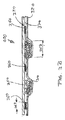
とりわけ液体の処理を目的としているサンドイッチ構造体、例えば吸収構造体内で使用するためのものについて言えば、接合ライン又は接合領域によって粒子状物質の集合体が隣りの集合体から完全に分断されないように設計すれば、優れた液体処理力を実現できることが分かっている。代表的な構造体を図3に示す。図3には、キャリア材320とカバー材330の間に配置した粒子状物質310を備えたサンドイッチ構造体300が描かれている。更に、隣り合う粒子集合体の間に配置されている接合点領域360及び経路領域370とともに、粒子集合体350が描かれている。
Especially for sandwich structures intended for liquid processing, for example for use in absorbent structures, so that the aggregate of particulate matter is not completely separated from the adjacent aggregate by the joining line or the joining area. It has been found that, if designed, excellent liquid handling power can be achieved. A typical structure is shown in FIG. FIG. 3 depicts a
更に今では、隣接し合う粒子集合体の間に接合領域を設けると、この領域には粒子が実質的に含まれていないため、接着剤やその他の手段によって各キャリア層をしっかり接合できるようになり、特に有用であることが分かっている。 Furthermore, now that a bonding area is provided between adjacent particle aggregates, the particles are substantially free of this area so that the carrier layers can be firmly bonded by adhesive or other means. Has proven to be particularly useful.
上記にもかかわらず、とりわけ前記サンドイッチ構造体が濡れた場合に、前記サンドイッチ構造体によって優れた不動化機能または吸収性粒子を実現させる必要がある。特に、前記サンドイッチ構造体を備えた吸収性構造体又は吸収性物品は、欧州特許第1,447,066号(Busamら、P&G)に記載されている含水不動化試験で50%超、好ましくは60%超、更に好ましくは80%超、及び最も好ましくは90%超の数字を示すようにする必要がある。 In spite of the above, it is necessary to realize an excellent immobilization function or absorbent particles with the sandwich structure, particularly when the sandwich structure is wet. In particular, the absorbent structure or absorbent article comprising the sandwich structure is more than 50%, preferably in the moisture immobilization test described in EP 1,447,066 (Busam et al., P & G), preferably The number should be greater than 60%, more preferably greater than 80%, and most preferably greater than 90%.
粒子状物質パターンには粒子集合体350が複数含まれており、各集合体には粒子310が複数含まれているものと考えられている。
The particulate matter pattern includes a plurality of particle aggregates 350, and each aggregate is considered to include a plurality of
前記粒子集合体(図3A及び図3B参照)に含有させる粒子はわずか10粒前後でもよいが、数百、更には数千粒でもよい。前記粒子は、実質的に「単層の」サンドイッチ構造体内又は厚さが実質的に一定の多層構造体内に配置してもよく、また、前記粒子の厚みは一定でなくてもよい。この厚みは、被覆粒子層の数で表しても、局部的または平均的な坪量(特定の単位面積あたりの粒子の重量)で表してもよい。当業者であればすでに気が付いているだろうが、「局部的な」坪量でも、ある程度の平均化は必要になると思われる。しかし、設計によって特定の領域の坪量をその領域にわたって不均一にした場合、例えば、顆粒状物質を山積みにするケースでは、領域の中央に行くほど厚みを増大させた場合、坪量の分布は、前記山積み状の顆粒状物質の断面図に従う時は、平滑曲線によって概算値を求めてよい。また別の方法として、領域の平均坪量を割り出せるように、また任意に応じてその領域の一定の変化性とともに前記平均坪量を割り出せるように、領域の坪量が領域全体にわたって一定になるように設計してもよい。隣接する領域の坪量についても同様にすることができるが、必ずしも上記のようにする必要はない。粒子集合体を平均した場合の典型的な坪量は、10g/m2以下〜500g/m2又は1,000g/m2である。パターン(すなわち、粒子集合体と各粒子集合体の間の領域の双方を含む。集合体の間の領域には粒子を実質的に全く含めなくてもよい)を平均した場合の典型的な坪量は、1g/m2〜400g/m2超又は800g/m2超である。
The particle aggregate (see FIGS. 3A and 3B) may contain only about 10 particles, but it may be several hundreds or even thousands. The particles may be disposed within a substantially “single layer” sandwich structure or a multilayer structure having a substantially constant thickness, and the thickness of the particles may not be constant. This thickness may be expressed by the number of coated particle layers or by a local or average basis weight (particle weight per specific unit area). As those skilled in the art are already aware, some “local” basis weights may require some degree of averaging. However, if the basis weight of a specific region is made uneven over the region by design, for example, in the case of a pile of granular materials, if the thickness is increased toward the center of the region, the distribution of the basis weight is When following the cross-sectional view of the piled granular material, an approximate value may be obtained by a smooth curve. Alternatively, the area basis weight may be constant over the entire area so that the average basis weight of the area can be determined, and optionally the average basis weight can be determined with certain variability in the area. You may design it. The basis weight of adjacent areas can be the same, but it is not always necessary to do so. Typical basis weights in the case of average particle assembly is 10 g / m 2 or less to 500 g / m 2 or 1,000 g / m 2. Typical grammage when averaging patterns (ie, including both particle aggregates and the areas between each particle aggregate; areas between aggregates may contain substantially no particles) the amount is 1g / m 2 ~400g /
集合体350は、長円形や楕円形といった様々な形態及び形状にしても、不揃いの形状にしてもよい。好ましい実施形態では、前記集合体は実質的に円形をしている。集合体の直径353は2mm超、好ましくは4mm超、かつ20mm未満、好ましくは8mm未満にしてよい。パターン380内で隣り合っている2つの集合体の間隔355は、2mm超、好ましくは5mm超、かつ30mm未満、好ましくは15mm未満、更に好ましくは7mm未満にしてよい。
The aggregate 350 may have various forms and shapes such as an oval or an ellipse, or may have an irregular shape. In a preferred embodiment, the assembly is substantially circular.
複数の集合体によって第1のパターンが形成されているが、このパターン内では、前記集合体は幾何学的な形で間隔を空けて配置されている。前記パターンに含まれる集合体の数はわずか2つであってもよいが、典型的には10個を超える。前記パターンに含まれる集合体の数は1,000個未満であることが多い。複数の集合体によって、第1のパターンの中に規則的又は不規則なサブパターンを形成させてもよい。前記集合体を別々に配置して、粒子が実質的に含まれていない領域に前記領域の各々が実質的に囲まれるようにしてもよい。粒子が含まれていない領域は、接合領域と同一である必要はない。 A first pattern is formed by a plurality of aggregates, within which the aggregates are spaced apart in a geometric form. The number of aggregates included in the pattern may be as small as two, but typically exceeds 10. The number of aggregates included in the pattern is often less than 1,000. A regular or irregular sub-pattern may be formed in the first pattern by a plurality of aggregates. The aggregates may be arranged separately so that each of the regions is substantially surrounded by a region that is substantially free of particles. The region that does not contain particles need not be the same as the junction region.
典型的には、粒子が互いに直接接触し合うように、すなわち、各粒子が少なくとも1つの他の粒子と接触するように粒子を配置する。だが、各粒子を接触させないケースもありうる。そして、ただし集合体内で隣り合っている粒子の間隔は通常、第1のパターンまたはサブパターン内で隣り合っている粒子集合体の間隔よりも短くなる。 Typically, the particles are arranged so that the particles are in direct contact with each other, ie, each particle is in contact with at least one other particle. However, there may be cases where each particle is not contacted. However, the interval between adjacent particles in the aggregate is usually shorter than the interval between adjacent particles in the first pattern or sub-pattern.
前記粒子パターンは実質的に切れ目なく続く配置で形成させるが、ある特定の反復パターンが発生するため、次に作られる物品で同じパターンが反復されることになると思われる。したがって、「マクロパターン」という用語は、各パターンによって前記物品の成分を形成させるような前記反復パターンを意味する。 Although the particle pattern is formed in a substantially uninterrupted arrangement, it is likely that the same pattern will be repeated on the next article to be produced as a certain repetitive pattern occurs. Thus, the term “macro pattern” refers to the repetitive pattern in which each pattern forms a component of the article.
いかなる別個の領域も、種々の一般的により広い連続領域を間に有する、反復パターンを形成する少なくとも2つの断続的な領域により形成されるなどの、マクロパターンに配置してよい。 Any separate regions may be arranged in a macro pattern, such as formed by at least two intermittent regions that form a repeating pattern with various generally wider continuous regions in between.
パターンは、図3の軸383によって示されているように、特性軸によって描写してよい。 The pattern may be depicted by a characteristic axis, as shown by axis 383 in FIG.
この軸は角度的に、おむつ20及び吸収性コアそれぞれの長手軸100に対してオフセットさせるのが好ましい。
This axis is preferably offset angularly relative to the
各集合体の間にある接合領域360は、切れ目なく続く領域よりも、断続的な領域にする方が好ましく、断続的な領域にすることで、経路領域370が集合体の間に形成されるのを防ぐことができる。接合点の形状および寸法は一定でなくてもよい。好ましい実施形態では、接合領域360は、約1mm以上、好ましくは2mm以上、更には約5mm以上の直径363を有する円形をしている。また、接合点領域の直径は約20mm未満、好ましくは約10mm未満であるのが好ましい。隣り合っている接合点の間隔365は主に集合体のパターンによって形成され、その長さは約5mm以上、好ましくは約10mm以上、かつ約20mm未満、好ましくは約15mm未満にしてよい。
The
パターンは一体型にすることも、サブパターンから構成させることもでき、各サブパターンには異なる直径又は間隔を持たせてもよい。サブパターン間の移行部にも漸進的な直径又は間隔を持たせてもよい。パターンは、後に作成する吸収性構造体、例えばおむつに合わせて、反復的なものにする必要がある。 The pattern can be integrated or can be composed of sub-patterns, and each sub-pattern can have a different diameter or spacing. The transition between sub-patterns may also have a gradual diameter or spacing. The pattern needs to be repetitive to fit the absorbent structure that will be created later, such as a diaper.
接合領域360に加えて周辺接合領域387を設けて、長手縁部又は終縁部でサンドイッチ構造体を封止するようにしてもよい。
In addition to the
パターン付きサンドイッチ構造体を製造する方法
ある特定の観点では、本発明は、キャリア材の間に挟み込んだ粒子状物質のパターンを備えたサンドイッチ構造体を製造する方法に関するものである。
Method for Producing Patterned Sandwich Structure In one particular aspect, the present invention relates to a method for producing a sandwich structure having a pattern of particulate matter sandwiched between carrier materials.
このような方法は、非常に正確かつ再現可能な状態で、高速又は超高速の生産速度によってパターンを生産できるものでなければならず、言い換えると、全体的な生産速度が、生産プロセス全体においてプロセス工程に制限を課すような速度でないのが好ましく、前記速度は0.5m/秒までにしてもよいが、10m/秒以上である場合が多い。更に前記プロセスは、頑丈かつ安価な機器設計を可能にするものでなければならない。 Such a method must be capable of producing patterns at very high and very high production rates in a very accurate and reproducible manner, in other words, the overall production rate is the process throughout the production process. Preferably, the speed is not such as to impose a limit on the process, and the speed may be up to 0.5 m / second, but is often 10 m / second or more. Furthermore, the process must allow for robust and inexpensive equipment design.
したがって本発明は、事前に設定した表面速度で移動可能な表面上に、所定のパターンで粒子状物質を配置する作業を実質的に絶え間なく行う方法に関するものである。前記パターンは通常、粒子状物質が含まれている領域と粒子上物質が実質的に含まれていない領域から構成される。 Accordingly, the present invention relates to a method for substantially continuously performing the work of placing particulate matter in a predetermined pattern on a surface that is movable at a preset surface velocity. The pattern is usually composed of a region containing particulate matter and a region substantially free of on-particle matter.
前記プロセスの概略図を図4で確認することができるが、図4では、粒子状物質投入装置410、キャリア材移送装置420及びカバー材供給装置430、キャリア支持手段470、オプション要素である粒子移送装置440が描かれている。更には、キャリア材320とカバー材330の間に配置された粒子状物質310を備えたサンドイッチ構造体300も描かれている。
A schematic diagram of the above process can be confirmed in FIG. 4. In FIG. 4, the particulate matter charging device 410, the carrier material transfer device 420, the cover
前記粒子状物質は通常、粒子貯蔵装置から前記プロセスの装置に投入し、通常はバルク状態で投入する。バルクとは、各粒子についての特性及びパラメータ(構成、寸法、形状、粒子密度など)、更には粒子の塊についての特性及びパラメータ(バルク密度、粒径分布又は流動性)によって粒子の塊を表したものである。 The particulate matter is typically charged from a particle storage device into the process equipment and is typically charged in bulk. The term “bulk” refers to a particle lump by the characteristics and parameters for each particle (configuration, size, shape, particle density, etc.), as well as the properties and parameters for the lump of particles (bulk density, particle size distribution or fluidity). It is a thing.
前記粒子状物質はウェブ材の可動面の上に配置する。したがって、前記プロセスは典型的に、バルク貯蔵装置からウェブ材の上に規則的なパターンで粒子を配置するものと説明することができる。 The particulate matter is disposed on the movable surface of the web material. Thus, the process can typically be described as placing particles in a regular pattern from a bulk storage device onto a web material.
前記プロセスでは、粒子性物質を正確な位置に配置することが求められるうえに、非常に速い「変換」速度の中の最高速度にも対応可能でなければならない(前記速度は、現在の枠組みの中では通常、可動表面の速度ということになる)。 The process requires the particulate material to be placed in the correct location and must be able to handle the highest of the very fast “conversion” speeds (the speed is that of the current framework). Inside it is usually the speed of the movable surface).
現在の粒子配置システムの多くは、背景技術の部分で述べたとおり、速度に大きく左右されるのが一般的で、前記速度で作動させると、位置決めや適用重量に関して容認しがたい問題やばらつきが発生する。 Many of the current particle placement systems, as described in the background section, are generally highly dependent on speed, and operating at these speeds can lead to unacceptable problems and variations in positioning and application weight. appear.
本明細書に参照として組み込まれている同時係属中の欧州特許出願(代理人生理番号CM2877FQ)は、吸収性物品、とりわけおむつ用に、キャリア層の上に吸収性ゲル化材を間接的に配置する(この時、粒剤はバルク貯蔵装置から移送装置に取り込まれる)方法を示すことによって、上記問題に対する解決策を提示している。図4では、移送装置440にはその表面上に凹部452があり、その凹部の数、寸法、位置によって、移送装置440によって取り込まれる超吸収性粒子310の量とパターンが決まる。移送装置440は、バルク貯蔵装置に隣接している投入位置442から排出位置448に移動可能である。排出位置448では、キャリア層320が移送装置と隣接している。更に移送装置には、移送装置440が排出位置448に移動中、超吸収性粒子を凹部の内側に保持する手段444、ならびに、放出合流位置448のキャリア層の上に前記粒子を放出する手段446が備わっている。これらの手段はそれぞれ真空状で、空気噴出し式であるのが好ましい。
A co-pending European patent application (Attorney Phys. No. CM2877FQ), incorporated herein by reference, indirectly places an absorbent gelling material on a carrier layer for absorbent articles, especially diapers. It presents a solution to the above problem by showing how to do this (at this time granules are taken from the bulk storage device into the transfer device). In FIG. 4, the
本発明は、事前に計量した粒子状物質310をキャリア材320に配置することによって、キャリア材の間に挟み込まれた粒子状物質を形成させる方法を提示している。前記キャリア材によってくぼみ328の特定のパターンを形成させる。つまり、前記キャリア材を平面状から変形させる。これは、キャリア材320をキャリア支持構造体470の上に配置して特定のパターンを形成させることによって実現する。前記パターンを形成させる構造成分475各々の間には実質的に空っぽのスペースがあり、キャリアウェブが膨張して前記空間の中に入り込めるようになっているが、これは、液体又は水透過性キャリア材320を通るガス(空気)流を発生させる真空吸引装置472によって実現させてよい。続いて、粒子状物質310を前記くぼみに配置して集合体350を形成させるが、粒子状物質は、くぼみの一部に配置しても、くぼみいっぱいに詰め込んでも、「山積み」にしてくぼみの体積以上の量を投入してもよい。前記のいずれのケースでも、キャリア材の少なくとも一部には粒子状物質が実質的に含まれていない。この区域は接合領域360といい、キャリア支持区域332と一致させても、また、前記区域よりも広く又は狭くしてもよい。
The present invention presents a method for forming a particulate material sandwiched between carrier materials by placing a pre-weighed
サンドイッチ構造体の形成作業は、くぼみ350のパターン付き粒子状物質をカバー材330で覆い、接着剤495を少なくともキャリア材の接合領域又はカバー材の対応区域に塗布するなどして2つのウェブ材を相互に固定させることによって完了する。
The sandwich structure is formed by covering the patterned particulate material of the
本発明では、キャリア材320はキャリア支持装置470の上に配置する。キャリア支持装置470には複数の表面があり、その表面は適切な速度でキャリア材と接触するようにしてよい。前記適切な速度は、前記表面がプロセス全体の速度と同じぐらいの速度で移動するようにすれば実現できる。
In the present invention, the
キャリア支持装置は円筒状にして、その長手軸を中心に回転可能な状態で配置してよい。そして、回転ドラムのシェル450のような外側の円筒面によって、キャリア材の支持領域を形成させる。更にキャリア支持装置には、実質的に無端の可動ベルトを搭載させてもよい。この可動ベルトは移送ローラーシステムの上に配置する。
The carrier support device may be cylindrical and arranged so as to be rotatable about its longitudinal axis. Then, a support region for the carrier material is formed by an outer cylindrical surface such as the
キャリア材320は、キャリア支持手段の「外」面、表向きにはドラムの外面、つまり可動ベルトの外面の反対側の面の上に配置する。この面は、ベルト支持ローラーの大半と接触している。
The
キャリアウェブは、キャリア支持区域477の上に配置する。キャリア支持装置のこのサブ領域は、実質的に全く張力が加わっていない状態でキャリア支持装置をキャリアの上に配置した場合にキャリアウェブと接触する区域である。したがって、キャリア支持手段が連続的(孔なし)ドラムだとしたら、キャリア支持区域は円筒面になる。キャリア支持手段が有孔ドラムだとしたら、キャリア支持区域は、有孔区域を除いた円筒面区域になる。キャリア支持装置が円筒形を織り成す格子状だとしたら、キャリア支持区域は、前記格子の骨組みのうちの外面に面している区域になる。 The carrier web is placed over the carrier support area 477. This sub-region of the carrier support device is the area that contacts the carrier web when the carrier support device is placed over the carrier with substantially no tension applied. Thus, if the carrier support means is a continuous (no hole) drum, the carrier support area is a cylindrical surface. If the carrier support means is a perforated drum, the carrier support area is a cylindrical surface area excluding the perforated area. If the carrier support device is a grid weaving a cylinder, the carrier support area is the area facing the outer surface of the grid framework.
ある好ましい実施形態では、キャリア支持区域は連続領域でなく、つまり、キャリア支持区域は「島」と表現することができ、例えば、円筒シェル450(図5参照)から突き出ているピン475によって形成させてよい。ピン457の外側の末端点を覆っている最外面は、キャリア支持区域477に相当する。支持ピンの横断面は長方形状にしてよい。ある好ましい実施形態では、支持ピンは円筒形をしており、その直径376は好ましくは1.5mm超、更に好ましくは5mm超、かつ15mm以下、更に好ましくは10mm以下である。ピンの最外面が平面(図6A及び図6B参照)ではなく、円形、楕円形または円形の断面状(図6Cおよび図6D参照)の場合、前記区域には、実質的に張力が加わっていない状態でキャリアウェブ支持材によって覆われる区域が投影された形になる。キャリア支持区域は隆起部によって形成させてもよく、この隆起部は直線でも曲線でもよく、また、十字状であってもよい(図6Eおよび図6F参照)。例えば、格子の交点に最外区域が形成されるように(図6Gおよび図6H参照)、キャリア支持区域は、格子または十字から突き出ているピンや高さの変動するピンなどの「ハイブリッド」構造体によって形成させてもよい。
In a preferred embodiment, the carrier support area is not a continuous region, that is, the carrier support area can be expressed as an “island”, for example formed by
したがって、キャリアウェブ手段は、(最外)キャリア支持区域によって支えられることが前提となっているが、以下に示すメカニズムによって、キャリア支持区域以外の区域内で内側に向かって放射状に膨張又は変形するようにしてもよい。 Thus, the carrier web means is assumed to be supported by the (outermost) carrier support area, but expands or deforms radially inward in areas other than the carrier support area by the mechanism shown below. You may do it.
ただし、一部のデザインでは、外側の被覆面でキャリア材を支持するのみならず、二次支持区域でもキャリア材を支持する方が適切な場合もある。前記区域は、変形させる力を加えずに適用した場合にはキャリア材と接触しないが、ウェブが変形(内向きに膨張)した場合に限りキャリア材と接触してキャリア材を支持する「高さの低い島」と例えることができる。例えば、ある特定の高さのキャリア支持ピンを一組設けて第1のキャリア支持区域が形成されるようにし、前記ピンよりも高さの低い第2のピンを一組設けて、第2の支持区域が形成されるようにすることができる(図6G及び図6H参照)。 However, in some designs it may be appropriate to support the carrier material not only in the outer covering surface but also in the secondary support area. The area does not contact the carrier material when applied without applying a deforming force, but only when the web is deformed (expands inward) to contact the carrier material to support the carrier material. Can be likened to a low island. For example, a set of carrier support pins having a specific height is provided so as to form a first carrier support area, and a set of second pins having a height lower than that of the pins is provided. Support areas can be formed (see FIGS. 6G and 6H).
キャリア支持区域によって、あらかじめ定めた特定のパターンを形成させる。このパターンは、サンドイッチ構造体の所望の粒子状物質のパターンと一致する。おおむねキャリアウェブ支持手段を覆うように伸びるx軸に合わせて、所定の角度を付けて配置されたマクロパターン(図5C参照)であるのが好ましい。このパターンは反復パターンにしてよく、典型的にはパターン付き吸収性サンドイッチ構造体のパターンを反映させたものになる。 A predetermined specific pattern is formed by the carrier support area. This pattern matches the pattern of desired particulate material of the sandwich structure. It is preferably a macro pattern (see FIG. 5C) arranged at a predetermined angle in accordance with the x-axis extending so as to cover the carrier web support means. This pattern may be a repetitive pattern, typically reflecting the pattern of the patterned absorbent sandwich structure.
更に、キャリア支持区域の直径はキャリア材の全体的特性に適合させる必要がある。例えば支持ピンを使う場合、各ピンの支持区域は重要区域よりも低い位置に配置する必要はなく、低い位置に配置すると、ウェブ内の局部応力によって、キャリアが破損するほど変形し、ピンがウェブの孔を突き破る場合がある。 Furthermore, the diameter of the carrier support area must be adapted to the overall properties of the carrier material. For example, when using support pins, the support area of each pin does not need to be located lower than the critical area. If it is placed at a low position, the local stress in the web will deform the carrier so that it will break, causing the pins to May break through the hole.
前記ピンは、隣り合うピンから5mmの位置に配置してもよく、前記間隔は20mm以上にしてもよい。前記ピンは円筒状にしてよい。支えるウェブ材の破損を防ぐために、各ピンには、実質的に外側を向いており、少なくとも3.5mm2、好ましくは10mm2で40mm2以下の面積を有する表面を設ける必要がある。ピンの外側方向の先端(ウェブと接触する部分)は円筒状でなくてもよい。前記接触区域は、張力が加わっていない状態のキャリア材によって形成される平面を変形させると、キャリア材と接触する先端の一部が投影された形になると見なされる。代替手段として、あるいは追加手段として、細長いピン又はリブ又は隆起部によって、キャリア支持パターンを別の幾何学的パターンの形状にしてもよい。前記ピン又はリブ又は隆起部は直線でも曲線でもよい。前記ピン又はリブ又は隆起部によって形成させるのは連続的なパターンでないのが好ましいが、2つ以上のリブを接合させて、例えば十字状の支持区域を形成させてもよい。キャリア材は、最終的に作られる構造体の要件(流体処理が必要な用途の場合の液体処理特性など)を満たしたものでなければならない。 The pins may be arranged at a position 5 mm from adjacent pins, and the interval may be 20 mm or more. The pin may be cylindrical. In order to prevent breakage of the supporting web material, each pin should be provided with a surface that is substantially outward and has an area of at least 3.5 mm 2 , preferably 10 mm 2 and 40 mm 2 or less. The tip of the pin in the outer direction (portion that contacts the web) may not be cylindrical. The contact area is considered to have a projected shape of a portion of the tip that contacts the carrier material when the plane formed by the carrier material in an untensioned state is deformed. As an alternative or in addition, the carrier support pattern may be in the form of another geometric pattern by elongated pins or ribs or ridges. The pin or rib or ridge may be straight or curved. Preferably, the pin or rib or ridge is not formed in a continuous pattern, but two or more ribs may be joined to form, for example, a cruciform support area. The carrier material must meet the requirements of the final structure to be produced (such as liquid handling characteristics for applications requiring fluid treatment).
更に、キャリア材には、工程中に力を加えた場合に変形する性能が備わっていなければならない。前記力は、さまざまな種類のものにすることができるが、最も好ましいのは、流体透過性キャリア材全体に流体を流すことによって生まれる抗力である。ある特定の好ましい実施形態では、キャリア材として有孔フィルム材又は更に好ましくは繊維ウェブを採用することによって、キャリア材に透気性を持たせてある。 Furthermore, the carrier material must have the ability to deform when a force is applied during the process. The force can be of various types, but most preferably is the drag created by flowing fluid through the fluid permeable carrier material. In certain preferred embodiments, the carrier material is made permeable by employing a perforated film material or more preferably a fibrous web as the carrier material.
空気透過性は素材の孔径と厚みに左右されるため、繊維材の場合には、繊維材の固有密度及び繊維の直径(複数の直径を備えた繊維の場合は直径分布)に左右される。更に、キャリア材には、粒子を保持する性能が備わっていなければならない。 Since the air permeability depends on the pore diameter and thickness of the material, in the case of a fiber material, it depends on the intrinsic density of the fiber material and the fiber diameter (diameter distribution in the case of a fiber having a plurality of diameters). Furthermore, the carrier material must have the ability to hold particles.
上述のとおり孔径によっては小粒子が貫通可能になるため、粒子を保持する性能は、キャリア材の透過性に左右されるものと思われる。原理上は望ましくないが、一定量の「微粉」を受容して貫通させるようにすることもできる。そしてこれは、後になってから修正してもよい。 As described above, depending on the pore diameter, small particles can penetrate, so the performance of holding the particles seems to depend on the permeability of the carrier material. Although not desirable in principle, a certain amount of “fine powder” can be received and penetrated. This may be corrected later.
本発明で重要なのは、キャリア材の変形特性である。変形とは、キャリアウェブ変形手段または固定手段によって力が加わると伸縮自在に(すなわち実質的に復元可能な状態で)変形すること、あるいは可塑的に変化することを指す。 What is important in the present invention is the deformation characteristics of the carrier material. Deformation refers to deformation in a stretchable manner (ie, in a substantially recoverable state) or plastic change when a force is applied by the carrier web deformation means or the fixing means.
本発明で一番多く使われるキャリア材は、長手方向(x軸方向)に伸びる組織と、前記組織と垂直に横方向(y軸方向)に伸びる組織を備えた実質的に平らなウェブである。 The carrier material most frequently used in the present invention is a substantially flat web having a structure extending in the longitudinal direction (x-axis direction) and a structure extending in the transverse direction (y-axis direction) perpendicular to the structure. .
いずれかの方向の力が加わると、その方向に沿ってウェブ材が伸長する。そして、ウェブ材には、その平面を力の方向と垂直に、またその厚みをz方向に変形させることによって前記伸長分を補う傾向がある。典型的には、ウェブ材については、縦方向(MD)及び横断方向(CD)に沿って測定される特性によって、例えば、応力・ひずみ特性を構築及び/又は前記特性の特定の特性点を定めることによって説明することができる。典型的には前記特性は、ウェブ材のストライプをクランプで固定して前記クランプに引張力を加えることによって割り出すことができる。前記キャリア材は更に、力学的特性、すなわち一定の荷重下におけるCD及びMD方向への伸長性によって特徴付けることもできる。前記特性は、従来どおり、クロスヘッド速度0.127m/分のラインクランプを使って応力・ひずみを測定することによって割り出してよい。CD方向の伸長性のMD方向の伸長性に対する割合は1〜0.2超であるのが好ましく、かつ1〜2以下であるのが好ましい。 When a force in either direction is applied, the web material extends along that direction. The web material tends to compensate for the elongation by deforming its plane perpendicular to the direction of force and its thickness in the z direction. Typically, for web materials, properties measured along the machine direction (MD) and transverse direction (CD), for example, build stress and strain characteristics and / or define specific characteristic points for the characteristics. Can be explained. Typically, the characteristic can be determined by fixing a web material stripe with a clamp and applying a tensile force to the clamp. The carrier material can also be characterized by mechanical properties, ie extensibility in the CD and MD directions under a constant load. The characteristics may be determined by measuring stress / strain using a line clamp with a crosshead speed of 0.127 m / min, as is conventional. The ratio of the extensibility in the CD direction to the extensibility in the MD direction is preferably more than 1 to 0.2, and preferably 1 to 2 or less.
本明細書で以下に記載されるように、有用なキャリア材には、その全体に流体を流すなどして力を加え、z方向に力がかかるようにする。ただし、キャリア支持ピンなどによってキャリア支持区域内でキャリア材を支えているため、このケースの変形動作はCD及びMD方向の変形特性によって決まる。したがって、前記特性は支持区域のパターンに合わせて調整する必要がある。 As described herein below, a useful carrier material is forced to flow in the z-direction, such as by flowing a fluid through it. However, since the carrier material is supported in the carrier support area by carrier support pins or the like, the deformation operation of this case is determined by the deformation characteristics in the CD and MD directions. Therefore, the characteristics need to be adjusted to the pattern of the support area.
キャリア材を一時的にキャリア支持手段に固定し、キャリア材保持手段によってキャリア材を水平/平面状態から変形させる。磁力に反応する素材の場合には磁力利用するなど、複数の物理的原理を用いてもよいが、特に好ましい実施形態ではウェブ全体に流体を流す方法をとっている。 The carrier material is temporarily fixed to the carrier support means, and the carrier material is deformed from the horizontal / planar state by the carrier material holding means. In the case of a material that reacts to a magnetic force, a plurality of physical principles such as the use of a magnetic force may be used. In a particularly preferred embodiment, a method of flowing a fluid over the entire web is adopted.
この方法を実現させるために、ウェブ材を通じて、特定の空間の、気体を抜き出すように調節した真空吸引装置472をキャリア支持手段に搭載してもよい。ウェブの多孔性に起因する流動抵抗を利用して、流体によってz方向の力を発生させて、ウェブの非支持部を変形させる。 In order to realize this method, a vacuum suction device 472 adjusted so as to extract gas in a specific space through the web material may be mounted on the carrier support means. By utilizing the flow resistance caused by the porosity of the web, a force in the z direction is generated by the fluid to deform the non-supporting portion of the web.
その結果、ウェブによってくぼみ328(図4B参照)が形成され、支持区域(支持ピンなど)によって上部が形成され、キャリア材の真空吸引力、透過性、応力・ひずみ特性の比率によって「谷底」が形成される。したがって、実質的に均質な素材のMDおよびCD方向の特性が同じ場合、ならびに、例えば、ウェブ支持構造が方眼状に配置した支持ピンから構成されている場合、くぼみによって、方眼の正方形の中央に最深部を持つ谷部が形成される。 As a result, a recess 328 (see FIG. 4B) is formed by the web, and an upper part is formed by the support area (support pin, etc.). It is formed. Thus, if the substantially homogeneous material has the same MD and CD orientation characteristics, and, for example, if the web support structure is composed of support pins arranged in a grid, the recess will cause a square in the center of the grid. A valley having the deepest part is formed.
ウェブ材が変形した結果、方形状に配置した支持ピンの2つの点を結ぶ空間曲線が形成されると、通常は曲線の長さの方が前記支持ピンの直線距離よりも長くなり、空間曲線の長さは、対角線上の2つの支持ピンの点を結んだ曲線が形成された場合に最長となり、前記曲線は通常、双曲線で近似可能な空間をたどる線である。 As a result of the deformation of the web material, when a space curve connecting two points of the support pins arranged in a square shape is formed, the length of the curve is usually longer than the linear distance of the support pins. Is the longest when a curve connecting the points of two support pins on a diagonal line is formed, and the curve usually follows a space that can be approximated by a hyperbola.
同様に、支持区域によって外面、つまり上記のケースでは、支持ピンの4つの端点を結んでできる正方形、すなわち吸引力を加える前のウェブカバーの区域が形成されるが、これは、くぼみを形成させる変形後のウェブ材の実表面積と対比することができる。 Similarly, the support area forms the outer surface, i.e., in the above case, the square formed by connecting the four end points of the support pin, i.e. the area of the web cover before the suction force is applied, which forms a recess. This can be compared with the actual surface area of the web material after deformation.
同様に、変形したウェブ材ならびに変形手段によって変形させる前のウェブ材の表面に囲まれる部分の体積は、変形後のキャリア材によって形成されるくぼみに合わせて定めることができる。前記体積は少なくとも30mm3、好ましくは少なくとも100mm3で1,000mm3未満であるのが好ましい。 Similarly, the volume of the deformed web material and the volume of the portion surrounded by the surface of the web material before being deformed by the deformation means can be determined in accordance with the depression formed by the deformed carrier material. The volume of at least 30 mm 3, is preferably preferably 1,000mm below 3 at least 100 mm 3.
この「くぼみの体積」は、くぼみに配置される粒子の体積と比較させることができる。設計対象に応じて、粒子集合体の体積は、くぼみの体積の5%超又は前記体積の50%超にしてよい。粒子を「くぼみの体積以上に投入する」(山積みにする)場合、投入量はくぼみの体積の150%以内にするのが典型である。 This “indentation volume” can be compared to the volume of the particles placed in the indentation. Depending on the design object, the volume of the particle assembly may be greater than 5% of the indentation volume or greater than 50% of the volume. When the particles are “added beyond the volume of the indentation” (stacked), the input is typically within 150% of the indentation volume.
キャリア材320を変形させてくぼみを形成させ、粒子状物質をくぼみの中又は上に投入した後、カバー材(典型的にはウェブ材)で被覆する。このカバー材は主に最終用途の要求によって決まる。カバー材はキャリア材と同じ素材にしてもよいし、ウェブ材中央のストライプ領域などの領域に粒子状物質を配置した後、素材の部分のうち横方向外側に向いている1つ又は複数の部分を長手方向の折り目に沿って粒子状物質を覆うようにして折り畳む場合などには、キャリア材と一体成形させてもよい。
The
また、キャリア材と素材は同じにして配置する際に切り離してもよいし、想定する用途にもキャリア材に接合させるのにも適している別の素材にしてもよい。 Further, the carrier material and the material may be separated when the same material is arranged, or may be another material suitable for the intended use and the carrier material.
キャリア材とカバー材を連結(例えば永久接合)させて、キャリア材とカバー材の間に粒子のパターンを備えた複合サンドイッチ構造体が形成されるようにする。この接合作業は、接着剤による接合や熱接合等の従来の手段で達成できる。 The carrier material and the cover material are connected (for example, permanently bonded) so that a composite sandwich structure having a particle pattern is formed between the carrier material and the cover material. This joining operation can be achieved by conventional means such as joining with an adhesive or thermal joining.
接合領域のウェブ材の間に配置した粒子によって接合が阻害されないようにするのが重要であることが分かっている。接合領域は、接合状態を永続的に確保するために欠かせない領域を指す。したがって、支持ピンによって支持区域を形成させた上記の例では通常、接合領域は前記支持区域と一致しているが、前記支持区域よりも多少狭く又は広くしてもよい。 It has been found that it is important that the bonding is not hindered by particles placed between the web materials in the bonding area. The joining region refers to a region that is indispensable for permanently securing the joining state. Therefore, in the above example where the support area is formed by the support pins, the joining area is usually coincident with the support area, but may be somewhat narrower or wider than the support area.
例えば、接着剤を噴霧する場合、接合区域の面積はパターン総面積の2%超、好ましくは7%超、かつ50%未満であるのが好ましいと思われる。接合区域は支持区域よりも広くてもよく、典型的には、くぼみが粒子状物質で満たされていない場合に前記ケースが発生する。支持ピンの位置で溶融接合させた場合には、接合区域は支持区域の50%にしかならないと思われる。 For example, when spraying the adhesive, it may be preferred that the area of the bonded area is greater than 2% of the total pattern area, preferably greater than 7% and less than 50%. The joint area may be wider than the support area, and typically the case occurs when the indentation is not filled with particulate matter. When melt bonded at the location of the support pins, the bonded area would only be 50% of the supported area.
以上のことから、接合領域には実質的に粒子状物質が含まれていないのが好ましい。用語「実質的に含まれていない」ということは、通常使用時に、前記区域内の粒子によって接着状態が阻害されてはならないことを意味する。 In view of the above, it is preferable that the joining region is substantially free of particulate matter. The term “substantially free” means that during normal use, the adhesion state should not be inhibited by particles in the area.
ただし、粒子状物質が広い粒度分布特性を備えている場合、あるいは、粒子が形成プロセス中粉砕される場合には、接合領域に一定量の「粉塵」が含まれていてもよい。「接合領域への粒子投入」量を算定する方法については、吸収性材料への適用に関する部分で後述する。 However, when the particulate material has a wide particle size distribution characteristic, or when the particles are pulverized during the formation process, a certain amount of “dust” may be included in the joining region. A method for calculating the “particle input into the bonding region” amount will be described later in the section on application to the absorbent material.
本発明を実現させるための必要な要素について説明し終えたので、以下では各プロセス工程について述べることとする。 Having described the necessary elements for realizing the present invention, each process step will be described below.
全体的には、サンドイッチ構造体は所定のパターンで粒子状物質を組み込んで形成するものと想定している。形成プロセスは実質的には連続工程であり、実質的に無端のウェブ材から着手し、バルク状で投入される粒子状物質と前記ウェブ材を組み合わせる。その結果得られた連続サンドイッチ複合物は、切断するなどして個々の断片に分離させてもよい。この断片の各々には、挟み込まれた粒子状物質の少なくともマクロパターンが含まれている。 Overall, it is assumed that the sandwich structure is formed by incorporating particulate material in a predetermined pattern. The forming process is substantially a continuous process, starting from a substantially endless web material and combining the web material with particulate material charged in bulk. The resulting continuous sandwich composite may be separated into individual pieces, such as by cutting. Each of the fragments includes at least a macro pattern of the sandwiched particulate matter.
以下では、各プロセス段階について更に詳しく説明するが、実施する順番に説明していくわけではない。 In the following, each process step will be described in more detail, but not in the order of execution.
a−外側のサンドイッチ層を形成するキャリア材及び/又はカバー材の役割を果たすものとして、実質的に平坦なウェブ材を用意する。したがって、このウェブ材は、一体成形した後に長手方向に折り畳むことによって外側の2つのサンドイッチ層の双方を形成させてもよい。また、2つのウェブ材を別々に用意し、一方のウェブ材によってキャリア材を形成させ、もう一方のウェブ材によってカバー材を形成させてもよい。好ましい手法においては、同種のウェブ材を2つ用意する。ウェブ材には、想定用途に対応できる特性が備わっていなければならない。これに加え、ならびにある好ましい実施形態では、キャリア材には、空気などの気体は透過させるが粒子は透過させない特性が備わっている。ある好ましい実施形態ではウェブ材は不織材料であり、更に好ましくは、1つ又は複数のスパンボンド層(S)と単一のメルトブロウン層を組み合わせてSMS、更に好ましくはSMMSタイプのウェブが形成されるようにしたものである。 a—A substantially flat web material is provided to serve as a carrier material and / or cover material for forming the outer sandwich layer. Therefore, the web material may be formed integrally and then folded in the longitudinal direction to form both outer two sandwich layers. Alternatively, two web materials may be prepared separately, the carrier material may be formed from one web material, and the cover material may be formed from the other web material. In a preferred method, two web materials of the same kind are prepared. The web material must have properties that can accommodate the intended use. In addition, as well as in certain preferred embodiments, the carrier material has the property of allowing gases such as air to permeate but not particles. In certain preferred embodiments, the web material is a nonwoven material, more preferably an SMS, more preferably an SMMS type web, formed by combining one or more spunbond layers (S) and a single meltblown layer. It is made to be done.
b−支持パターンを備えているキャリアを支持するための、実質的に無段の支持手段(好ましくは外側のシリンダー又はシェル面の上に支持パターンが備わっている回転ドラム)を配置する。キャリア支持パターンは、キャリア支持ピンによって形成させるのが好ましい。前記ピンはキャリア支持手段の外面方向に向かって走らせるが、通常は前記ピンの外向きの区域を覆うことによって説明することができる。 b—Placing a substantially stepless support means (preferably a rotating drum with a support pattern on the outer cylinder or shell surface) for supporting a carrier with a support pattern. The carrier support pattern is preferably formed by carrier support pins. The pins run in the direction of the outer surface of the carrier support means, but can usually be explained by covering the outward area of the pins.
c−キャリア材を固定してキャリア材にくぼみを形成させるために、キャリア材保持手段を作動させる。キャリア装置が回転シェルを備えた回転ドラムであり、キャリア材が前記シェル上に配置される空気透過性素材である好ましい実施形態では、キャリア材保持手段はドラム内部の真空吸引装置にしてもよい。これは、ドラム表面の下に回転しない真空ボックスを設けることによって実現させてもよい。真空ボックスを設けることによって、キャリア材を通じて空気が吸い込まれてウェブ上に力が加わり、ウェブがドラム表面の上に固定されて、非支持領域部分のウェブが変形する。吸引力、すなわち、真空の度合は、ウェブの透過性特性、非支持区域、所望の変形部(すなわちくぼみの大きさ)によって決まる。 c—activate the carrier material retaining means to fix the carrier material and form a recess in the carrier material. In a preferred embodiment in which the carrier device is a rotating drum with a rotating shell and the carrier material is an air permeable material disposed on the shell, the carrier material holding means may be a vacuum suction device inside the drum. This may be achieved by providing a non-rotating vacuum box below the drum surface. By providing the vacuum box, air is sucked through the carrier material and a force is applied on the web, the web is fixed on the drum surface, and the web in the unsupported area portion is deformed. The suction force, ie the degree of vacuum, depends on the permeability characteristics of the web, the unsupported area, the desired deformation (ie the size of the indentation).
d−キャリア材は、キャリアウェブ支持手段及び変形手段の方向に適切な速度で走らせる。例えば、キャリア材は、キャリア支持ドラムの放射状の外面の速度に合わせて0.5m/秒超、更に好ましくは5m/秒超のキャリア速度で動かす。 d-Carrier material is run at an appropriate speed in the direction of the carrier web support means and the deformation means. For example, the carrier material is moved at a carrier speed of greater than 0.5 m / second, more preferably greater than 5 m / second, in accordance with the speed of the radial outer surface of the carrier support drum.
e−次の工程として、粒子状物質、例えば従来型の超吸収性粒子を用意する。この物質はホッパーなどのバルク状で用意するのが好ましい。 e—For the next step, a particulate material, such as conventional superabsorbent particles, is provided. This material is preferably prepared in a bulk form such as a hopper.
f−前記物質を計量して、最終製品のニーズに応じた量を投入する。この投入作業は、時間に対して一定でも不規則でもよい。ある好ましい実施形態では、投入の際に最終製品のニーズに合わせて粒子集合体をあらかじめ一定のパターンで形成させる。 f-Weigh the substance and put in an amount according to the needs of the final product. This input operation may be constant or irregular with respect to time. In a preferred embodiment, the particle aggregate is formed in a predetermined pattern in advance according to the needs of the final product at the time of input.
g−続いてキャリア材の外面(キャリア材の受容面)に粒子状物質を移動させると同時に、ウェブ支持手段のウェブ支持区域によってキャリア材を支えるとともに、キャリア材を変形させて非支持領域内にくぼみを形成させる。 g—Subsequently, the particulate material is moved to the outer surface of the carrier material (the receiving surface of the carrier material), and at the same time, the carrier material is supported by the web support area of the web support means, and the carrier material is deformed into the non-support region. Make a dimple.
h−更に、キャリア材とカバー材を固定すると同時に、粒子パターンを保持させるためにサンドイッチ固定手段を作動する。ある好ましい実施形態では、前記固定手段は、粒子をキャリア材の上に移動させる前及び/又はさせた後にスプレー式接着剤の噴霧することである。キャリア材とカバー材に同様の融解特性が備わっている場合には、接合手段として超音波などによる熱融着を採用してもよい。キャリア材およびカバー材は、接合区域内で接合させる。接合区域は、少なくともウェブ支持区域を覆うことによって定めることができるが、典型的には前記接合区域はウェブ支持区域の長手及び横方向外側に向かって伸び、支持区域の2%超、好ましくは7%超、かつ50%未満の区域をカバーする。接合区域には実質的に粒子が含まれていないのが好ましい。この要件については、接合領域内の粒子を測定する方法によって判断することができる。この方法については後述する。任意に応じて、接合手段を粒子に適用してもよい。 h—Further, the sandwich fixing means is actuated to fix the carrier pattern and the cover material while holding the particle pattern. In a preferred embodiment, the fixing means is spraying with a spray adhesive before and / or after the particles have been transferred onto the carrier material. If the carrier material and the cover material have similar melting characteristics, heat fusion by ultrasonic waves or the like may be employed as the joining means. The carrier material and the cover material are joined in the joining area. The joining area can be defined by covering at least the web support area, but typically said joining area extends outward in the longitudinal and lateral direction of the web support area and is greater than 2% of the support area, preferably 7 Cover areas greater than and less than 50%. It is preferred that the joining area is substantially free of particles. This requirement can be determined by the method of measuring particles in the bonded area. This method will be described later. Optionally, joining means may be applied to the particles.
i−粒子をキャリア材の上に配置した後、カバー材を配置してキャリア材と接合させて、サンドイッチ構造を閉鎖する。この工程を行うのが好ましいが、行うか否かは任意である。サンドイッチ固定手段によって前記構造に十分に一体性をもたらすことができ、かつ、サンドイッチのような構造を実現できる場合にはカバー材を追加する必要がないため、本発明に従い、キャリア材は備えているがカバー材は備えていないサンドイッチ構造体を採用することもできる。 After the i-particles are placed on the carrier material, a cover material is placed and joined to the carrier material to close the sandwich structure. Although it is preferable to perform this process, it is arbitrary whether or not it is performed. In accordance with the present invention, the carrier material is provided because the sandwich fixing means can provide sufficient integrity to the structure and there is no need to add a cover material if a sandwich-like structure can be realized. However, a sandwich structure having no cover material may be employed.
上記プロセス中に重要なのは、ウェブ支持手段の支持パターン領域のみでキャリアウェブを支えること、ならびにキャリア保持手段によってキャリア材を変形させて非支持領域にくぼみが形成されるようにすることである。これによって、第1のパターン(任意に応じてサブパターンも含まれる)が形成される。事前に計量した粒子状物質は、実質的にはこのくぼみの中のみに投入するのが好ましく、その投入量はくぼみの体積の5%以上、150%以下であるのが好ましい。 What is important during the above process is that the carrier web is supported only by the support pattern area of the web support means and that the carrier material is deformed by the carrier holding means so that depressions are formed in the non-support areas. As a result, a first pattern (including a sub-pattern if necessary) is formed. The pre-weighed particulate matter is preferably introduced substantially only into the indentation, and the input amount is preferably 5% or more and 150% or less of the volume of the indentation.
接合領域に粒子が含まれていないことを確認する方法
この試験の目的は、粒子状物質、とりわけ超吸収性物質の混入について接合区域を評価することにある。
Method for confirming that the bonded area is free of particles The purpose of this test is to evaluate the bonded area for contamination with particulate matter, especially superabsorbent material.
紫色ブロモクレゾール指示薬(CAS番号115−40−2)1.5gを脱イオン水10lで希釈してから1モル/リットルの塩酸(1N HCl)を4ml加えて試液を作成する。例えば先の尖ったピペットで前記試液を滴下して加え、又は 細かい噴霧ボトルを使用することにより、試験片を前記試液で濡らす。試液の投与量は試料の大きさ及び超吸収素材の量によって決まる。次の工程として各領域に対して行われる目視集計を実施しやすいように、対象領域内のすべての粒子は十分に濡らす必要がある。評価作業の補助手段として、適切な倍率の虫眼鏡や顕微鏡を使用してもよい。大きさが一般にキャリア及び/又はカバー材の孔径ほどである超微粒子(「粉塵」ともいう)は勘定に入れない。検出された粒子の数が2つ未満だった場合には、「超吸収性粒子が全く含まれていない」領域として分類する。接合領域内の粒子の占める面積が接合領域の面積の約50%超だった場合には、「超吸収性粒子が実質的に含まれていない」領域として分類する。 A test solution is prepared by diluting 1.5 g of purple bromocresol indicator (CAS No. 115-40-2) with 10 l of deionized water and then adding 4 ml of 1 mol / l hydrochloric acid (1N HCl). For example, wet the specimen with the reagent by adding the reagent dropwise with a pointed pipette or by using a fine spray bottle. The dose of the reagent depends on the sample size and the amount of superabsorbent material. All particles in the target area need to be sufficiently wetted so that visual aggregation performed on each area as a next step can be easily performed. As an auxiliary means for the evaluation work, a magnifying glass or a microscope with an appropriate magnification may be used. Ultrafine particles (also referred to as “dust”) that are generally about the size of the carrier and / or cover material pores are not counted. When the number of detected particles is less than two, it is classified as a region that does not contain any superabsorbent particles. When the area occupied by the particles in the bonding area is more than about 50% of the area of the bonding area, the area is classified as “substantially free of superabsorbent particles”.
「発明を実施するための最良の形態」で引用した全ての文献は、その関連部分において参考として本明細書に組み込まれ、いずれの文献の引用も、それが本発明に関する従来技術であることを認めるものとして解釈すべきではない。 All documents cited in “Best Mode for Carrying Out the Invention” are incorporated herein by reference in their relevant parts, and any citation of any document is considered to be prior art with respect to the present invention. It should not be interpreted as an admission.
本発明の特定の実施形態について例示および説明したが、本発明の精神および範囲から逸脱することなく、その他の様々な変更および修正が可能なことは当業者には明白である。 While particular embodiments of the present invention have been illustrated and described, it would be obvious to those skilled in the art that various other changes and modifications can be made without departing from the spirit and scope of the invention.
本明細書で数値を示した各パラメータは技術的パラメータであり、本明細書においては厳密な数字とは見なさないものとする。したがって、ここで述べたパラメータと機能的に同等のパラメータが示されている実施形態はすべて、本発明の範囲内のものであり、例えば長さ「10mm」は「約10mm」を指しているものとして理解しなければならない。 Each parameter indicated as a numerical value in the present specification is a technical parameter, and is not regarded as an exact number in this specification. Accordingly, all embodiments in which parameters functionally equivalent to those described herein are shown are within the scope of the present invention, for example, a length of “10 mm” refers to “about 10 mm” Must be understood as.
Claims (17)
a)キャリア材(320)及び/又はカバー材(330)として、少なくとも1つの本質的に平坦なウェブ材を提供する工程と、
b)支持パターンを有する、前記キャリア材(320)用の本質的に無端の支持手段(470)を提供する工程と、
c)キャリア材保持手段(472)を提供する工程と、
d)前記支持手段(470)の上方に前記キャリア材(320)を位置決めする工程であって、
これにより、前記キャリア材(320)が前記支持パターンとその支持面で接触し、
且つ、キャリア材と前記キャリア支持手段の接触面との間の相対速度が本質的に0である、
工程と、
e)粒子状物質(310)を提供する工程と、
f)前記粒子状物質(310)を予備計量する工程と、
g)サンドイッチ固定手段(495)を提供する工程と、
h)好ましくは前記カバー材(330)を前記キャリア材(320)と組合せると共に前記粒子状物質(310)がこれら2つの間に挟まれる工程と、を備え、
i)前記キャリア材(320)が前記支持手段の前記支持パターンの領域のみで支持され、
j)前記キャリア材(320)が前記キャリア保持手段(472)によって変形され、これにより、くぼみ(328)が非支持領域に形成され、
k)及び、前記粒子状物質(310)が前記キャリア材(320)に移送されて前記くぼみ(328)の中に入れられ、
これにより、粒子状物質の主なパターンを形成する、ことを特徴とする、サンドイッチ構造体を製造するための方法。 A method for manufacturing a sandwich structure (300) comprising a pattern of particulate matter (310) comprising:
a) providing at least one essentially flat web material as carrier material (320) and / or cover material (330);
b) providing an essentially endless support means (470) for the carrier material (320) having a support pattern;
c) providing carrier material retaining means (472);
d) positioning the carrier material (320) above the support means (470),
Thereby, the said carrier material (320) contacts the said support pattern and its support surface,
And the relative velocity between the carrier material and the contact surface of the carrier support means is essentially zero,
Process,
e) providing particulate matter (310);
f) pre-weighing said particulate matter (310);
g) providing a sandwich fastening means (495);
h) preferably combining the cover material (330) with the carrier material (320) and sandwiching the particulate matter (310) between the two,
i) the carrier material (320) is supported only in the region of the support pattern of the support means;
j) The carrier material (320) is deformed by the carrier holding means (472), whereby a recess (328) is formed in the unsupported region,
k) and the particulate matter (310) is transferred to the carrier material (320) and placed in the recess (328);
A method for producing a sandwich structure, characterized in that this forms a main pattern of particulate matter.
Applications Claiming Priority (3)
| Application Number | Priority Date | Filing Date | Title |
|---|---|---|---|
| EP04017789A EP1621165B1 (en) | 2004-07-28 | 2004-07-28 | Indirect printing of AGM |
| EP04017789.1 | 2004-07-28 | ||
| PCT/US2005/026831 WO2006015138A1 (en) | 2004-07-28 | 2005-07-28 | Process for producing absorbent core structures |
Publications (2)
| Publication Number | Publication Date |
|---|---|
| JP2008507384A true JP2008507384A (en) | 2008-03-13 |
| JP4995082B2 JP4995082B2 (en) | 2012-08-08 |
Family
ID=46705190
Family Applications (1)
| Application Number | Title | Priority Date | Filing Date |
|---|---|---|---|
| JP2007523817A Expired - Lifetime JP4995082B2 (en) | 2004-07-28 | 2005-07-28 | Method for manufacturing absorbent core structure |
Country Status (14)
| Country | Link |
|---|---|
| US (1) | US7744713B2 (en) |
| EP (2) | EP1621166B2 (en) |
| JP (1) | JP4995082B2 (en) |
| KR (1) | KR20070029270A (en) |
| CN (1) | CN101018521B (en) |
| AR (1) | AR050687A1 (en) |
| AU (1) | AU2005269401B2 (en) |
| BR (1) | BRPI0513820B8 (en) |
| CA (1) | CA2575467C (en) |
| ES (1) | ES2351793T3 (en) |
| MX (1) | MX2007001002A (en) |
| PL (1) | PL1621166T5 (en) |
| WO (1) | WO2006015138A1 (en) |
| ZA (1) | ZA200700388B (en) |
Cited By (29)
| Publication number | Priority date | Publication date | Assignee | Title |
|---|---|---|---|---|
| JP2010529900A (en) * | 2007-06-18 | 2010-09-02 | ザ プロクター アンド ギャンブル カンパニー | Disposable absorbent article comprising a sealed absorbent core comprising a substantially continuously distributed absorbent particulate polymer material |
| JP2010529879A (en) * | 2007-06-18 | 2010-09-02 | ザ プロクター アンド ギャンブル カンパニー | Disposable absorbent article with an improved capture system having a substantially continuously distributed absorbent particulate polymer material |
| JP2010529877A (en) * | 2007-06-18 | 2010-09-02 | ザ プロクター アンド ギャンブル カンパニー | Disposable absorbent articles with improved absorption characteristics having substantially continuously distributed absorbent particulate polymer material |
| JP2010529898A (en) * | 2007-06-18 | 2010-09-02 | ザ プロクター アンド ギャンブル カンパニー | Disposable absorbent articles and methods comprising substantially continuously distributed absorbent particulate polymer material |
| JP2011526812A (en) * | 2008-07-02 | 2011-10-20 | ザ プロクター アンド ギャンブル カンパニー | Disposable absorbent articles with various distributions of absorbent particulate polymer materials and methods for making the same |
| JP2012500669A (en) * | 2008-08-26 | 2012-01-12 | ザ プロクター アンド ギャンブル カンパニー | Method and apparatus for making disposable absorbent articles having absorbent dispersively distributed absorbent particulate polymer material and articles made there |
| WO2012108331A1 (en) * | 2011-02-10 | 2012-08-16 | 株式会社瑞光 | Method and apparatus for arranging granular material |
| WO2012108330A1 (en) * | 2011-02-10 | 2012-08-16 | 株式会社瑞光 | Method and apparatus for arranging granular material |
| JP2012527267A (en) * | 2009-05-20 | 2012-11-08 | ビーエーエスエフ ソシエタス・ヨーロピア | Water-absorbing storage layer |
| CN102781384A (en) * | 2010-02-26 | 2012-11-14 | 尤妮佳股份有限公司 | Device for manufacturing absorption structure |
| JP2013017563A (en) * | 2011-07-08 | 2013-01-31 | Livedo Corporation | Apparatus for manufacturing sheet member for absorbent article |
| JP2013017565A (en) * | 2011-07-08 | 2013-01-31 | Livedo Corporation | Apparatus for manufacturing sheet member for absorbent article |
| JP2013017562A (en) * | 2011-07-08 | 2013-01-31 | Livedo Corporation | Apparatus for manufacturing sheet member for absorbent article |
| JP2013017566A (en) * | 2011-07-08 | 2013-01-31 | Livedo Corporation | Particle supplying apparatus and apparatus for manufacturing sheet member for absorbent article |
| JP2013119002A (en) * | 2011-12-08 | 2013-06-17 | Kao Corp | Production device for absorber |
| JP2013529512A (en) * | 2010-06-25 | 2013-07-22 | ザ プロクター アンド ギャンブル カンパニー | Disposable diapers with reduced bulk |
| JP2013540024A (en) * | 2010-10-20 | 2013-10-31 | フィンカ ベーフェーベーアー | Method and apparatus for manufacturing an environmentally friendly absorbent structure |
| WO2014010365A1 (en) | 2012-07-13 | 2014-01-16 | 株式会社瑞光 | Device for manufacturing absorbent product |
| JP2014530695A (en) * | 2011-10-24 | 2014-11-20 | ボスティック,インコーポレイテッド | Novel process for producing absorbent articles |
| JP2016506266A (en) * | 2012-12-21 | 2016-03-03 | ボスティク インコーポレーテッド | Fluid absorbent article |
| WO2016103801A1 (en) * | 2014-12-25 | 2016-06-30 | ユニ・チャーム株式会社 | Method for producing absorbent article and device for producing absorbent article |
| WO2016148194A1 (en) * | 2015-03-16 | 2016-09-22 | 大王製紙株式会社 | Absorbent article |
| JP2017176504A (en) * | 2016-03-30 | 2017-10-05 | 大王製紙株式会社 | Absorber manufacturing method and absorber manufacturing apparatus |
| JP2017189645A (en) * | 2017-07-18 | 2017-10-19 | 大王製紙株式会社 | Absorber manufacturing method and absorber manufacturing apparatus |
| JP2017189644A (en) * | 2017-07-18 | 2017-10-19 | 大王製紙株式会社 | Absorber manufacturing method and absorber manufacturing apparatus |
| CN109475438A (en) * | 2016-07-19 | 2019-03-15 | 花王株式会社 | Manufacturing apparatus of absorber and manufacturing method of absorber |
| US10682267B2 (en) | 2015-10-06 | 2020-06-16 | Fameccanica, Data S.P.A. | Method and apparatus for producing an absorbent structure |
| CN115105301A (en) * | 2022-05-24 | 2022-09-27 | 山东爸爸的选择健康科技有限公司 | Manufacturing method of absorption core body with fast diffusion and accumulation prevention |
| JP2025538119A (en) * | 2022-12-02 | 2025-11-26 | ザ プロクター アンド ギャンブル カンパニー | Process for making non-fibrous water-soluble products |
Families Citing this family (118)
| Publication number | Priority date | Publication date | Assignee | Title |
|---|---|---|---|---|
| DE60323810D1 (en) | 2003-02-12 | 2008-11-13 | Procter & Gamble | Comfortable diaper |
| EP2177189B1 (en) | 2003-02-12 | 2015-11-04 | The Procter and Gamble Company | Absorbent core for an absorbent article |
| US7497133B2 (en) | 2004-05-24 | 2009-03-03 | Drexel University | All electric piezoelectric finger sensor (PEFS) for soft material stiffness measurement |
| US8241263B2 (en) | 2005-08-26 | 2012-08-14 | Medline Industries, Inc. | Absorbent article |
| JP4724587B2 (en) * | 2006-03-31 | 2011-07-13 | 大王製紙株式会社 | Absorbent articles |
| US8148598B2 (en) * | 2006-02-22 | 2012-04-03 | Dsg Technology Holdings Limited | Method of making an absorbent composite and absorbent articles employing the same |
| PL2043576T3 (en) | 2006-07-20 | 2013-03-29 | Essity Hygiene & Health Ab | An apparatus and method for forming air-laid absorbent cores |
| EP2043575B1 (en) * | 2006-07-20 | 2014-08-20 | SCA Hygiene Products AB | A mat-forming wheel |
| US8178035B2 (en) * | 2006-07-20 | 2012-05-15 | Sca Hygiene Products Ab | Apparatus and method for forming air-laid absorbent cores |
| JP4903865B2 (en) * | 2006-07-20 | 2012-03-28 | エスセーアー・ハイジーン・プロダクツ・アーベー | Apparatus and method for forming an airlaid absorbent core |
| DE102006042145B3 (en) * | 2006-09-06 | 2007-10-31 | Michael Dehn | Ventilation insert for use in e.g. electronic device, has absorber arranged on air-permeable layer that swells during contact with water, another air-permeable layer, and covers provided above air-permeable layers |
| WO2008067386A2 (en) * | 2006-11-28 | 2008-06-05 | Drexel University | Piezoelectric microcantilever sensors for biosensing |
| US8258367B2 (en) * | 2006-11-29 | 2012-09-04 | The Procter & Gamble Company | Disposable absorbent articles having an interior design signal |
| PL1974705T3 (en) * | 2007-03-26 | 2014-06-30 | Fameccanica Data Spa | Absorbing element for sanitary products, having expandable pockets containing superabsorbent material and manufacturing process |
| WO2009079154A2 (en) * | 2007-11-23 | 2009-06-25 | Drexel University | Lead-free piezoelectric ceramic films and a method for making thereof |
| WO2009126378A2 (en) | 2008-03-11 | 2009-10-15 | Drexel University | Enhanced detection sensitivity with piezoelectric microcantilever sensors |
| CA2722538C (en) | 2008-04-29 | 2014-08-12 | The Procter & Gamble Company | Process for making an absorbent core with strain resistant core cover |
| AU2009246115A1 (en) | 2008-05-16 | 2009-11-19 | Drexel University | System and method for evaluating tissue |
| DE102008063229A1 (en) | 2008-12-19 | 2010-07-01 | Dehn, Michael C. | Felt material with barrier function and component made of felt |
| RU2555615C2 (en) * | 2009-05-20 | 2015-07-10 | Као Корпорейшн | Absorbing body and absorbing product |
| US8722427B2 (en) | 2009-10-08 | 2014-05-13 | Drexel University | Determination of dissociation constants using piezoelectric microcantilevers |
| JP5469994B2 (en) * | 2009-10-19 | 2014-04-16 | ユニ・チャーム株式会社 | Method and apparatus for reducing absorber thickness |
| JP5581034B2 (en) * | 2009-10-19 | 2014-08-27 | ユニ・チャーム株式会社 | Absorber manufacturing method and manufacturing apparatus |
| EP2329803B1 (en) | 2009-12-02 | 2019-06-19 | The Procter & Gamble Company | Apparatus and method for transferring particulate material |
| KR20120091391A (en) * | 2009-12-04 | 2012-08-17 | 가오 가부시키가이샤 | Method and device for manufacturing absorption body |
| JP5383554B2 (en) * | 2010-02-26 | 2014-01-08 | ユニ・チャーム株式会社 | Absorber manufacturing equipment |
| EP2386277B1 (en) * | 2010-04-20 | 2013-11-13 | The Procter and Gamble Company | Apparatus and method for receiving and transferring solid material |
| EP2563413B1 (en) | 2010-04-30 | 2017-09-13 | The Procter and Gamble Company | Nonwoven having durable hydrophilic coating |
| EP2394618B1 (en) | 2010-06-09 | 2012-12-19 | The Procter & Gamble Company | Apparatus and method for retaining and releasing solid material |
| ES2401548T3 (en) * | 2010-07-27 | 2013-04-22 | The Procter And Gamble Company | Equipment and procedure for transferring a substrate material and a particulate material |
| EP2810630B1 (en) | 2010-10-13 | 2018-02-21 | Drylock Technologies NV | Absorbent structure |
| US11020280B2 (en) * | 2010-10-13 | 2021-06-01 | Romanova Bvba Starter | Method and Apparatus for Producing Composite Structure |
| EP2444044A1 (en) | 2010-10-13 | 2012-04-25 | Romanova bvba starter | Method and apparatus for producing absorbent structures |
| CA3047243C (en) | 2010-10-19 | 2022-04-12 | Medline Industries, Inc. | Absorbent articles and methods of manufacturing the same |
| US10117792B2 (en) | 2010-10-19 | 2018-11-06 | Medline Industries, Inc. | Absorbent articles and methods of manufacturing the same |
| ITBO20110186A1 (en) * | 2011-04-08 | 2012-10-09 | Gdm Spa | METHOD AND UNIT FOR THE IMPLEMENTATION OF PADDING FOR HYGIENIC ABSORBENT ITEMS. |
| PL2532332T5 (en) | 2011-06-10 | 2018-07-31 | The Procter And Gamble Company | Disposable diapers with a reduced connection between the absorbent body and the underlayer |
| CA3042501C (en) | 2011-06-10 | 2020-06-23 | The Procter & Gamble Company | An absorbent core for disposable diapers comprising longitudinal channels |
| MX2013014588A (en) | 2011-06-10 | 2014-01-24 | Procter & Gamble | Absorbent structure for absorbent articles. |
| EP2532334B1 (en) * | 2011-06-10 | 2016-10-12 | The Procter and Gamble Company | Absorbent core for disposable absorbent article |
| SG195105A1 (en) | 2011-06-10 | 2013-12-30 | Procter & Gamble | Absorbent core for disposable absorbent articles |
| EP2532329B1 (en) | 2011-06-10 | 2018-09-19 | The Procter and Gamble Company | Method and apparatus for making absorbent structures with absorbent material |
| DE202012013564U1 (en) | 2011-06-10 | 2017-11-13 | The Procter & Gamble Company | Absorption structure for absorbent article |
| ES2459724T3 (en) * | 2011-06-10 | 2014-05-12 | The Procter & Gamble Company | Method and apparatus for making absorbent structures with absorbent material |
| JP5814016B2 (en) | 2011-07-08 | 2015-11-17 | 株式会社リブドゥコーポレーション | Particle supply apparatus and sheet member manufacturing apparatus for absorbent articles |
| USD716938S1 (en) | 2011-10-19 | 2014-11-04 | Medline Industries, Inc. | Absorbent core |
| EP2586412A1 (en) | 2011-10-24 | 2013-05-01 | Bostik SA | New absorbent article and process for making it |
| EP2586409A1 (en) | 2011-10-24 | 2013-05-01 | Bostik SA | New absorbent article and process for making it |
| EP2586410A1 (en) * | 2011-10-24 | 2013-05-01 | Bostik SA | Novel process for preparing an absorbent article |
| EP2609898A1 (en) | 2011-12-29 | 2013-07-03 | Bostik SA | Novel process for preparing an absorbent article |
| EP2644174A1 (en) | 2012-03-29 | 2013-10-02 | The Procter and Gamble Company | Method and apparatus for making personal hygiene absorbent articles |
| EP2671554B1 (en) | 2012-06-08 | 2016-04-27 | The Procter & Gamble Company | Absorbent core for use in absorbent articles |
| EP2679210B1 (en) | 2012-06-28 | 2015-01-28 | The Procter & Gamble Company | Absorbent articles with improved core |
| WO2014007043A1 (en) * | 2012-07-04 | 2014-01-09 | 株式会社瑞光 | Ultrasonic bonding method for absorbent article, ultrasonic bonding device for absorbent article, and absorbent article |
| GB2503924A (en) | 2012-07-13 | 2014-01-15 | Glatfelter Switzerland Sarl | Super-absorbent sandwich web |
| WO2014021189A1 (en) * | 2012-08-02 | 2014-02-06 | 株式会社瑞光 | Composite sheet production method and device |
| CN105380754B (en) | 2012-11-13 | 2020-11-27 | 宝洁公司 | Absorbent article with channels and indicia |
| US9265672B2 (en) | 2012-11-27 | 2016-02-23 | The Procter & Gamble Company | Methods and apparatus for applying adhesives in patterns to an advancing substrate |
| US20140148773A1 (en) | 2012-11-27 | 2014-05-29 | The Procter & Gamble Company | Absorbent Articles with Substrates Having Patterned Slot Coated Adhesives |
| US9248054B2 (en) | 2012-11-27 | 2016-02-02 | The Procter & Gamble Company | Methods and apparatus for making elastic laminates |
| US9295590B2 (en) | 2012-11-27 | 2016-03-29 | The Procter & Gamble Company | Method and apparatus for applying an elastic material to a moving substrate in a curved path |
| US9216116B2 (en) | 2012-12-10 | 2015-12-22 | The Procter & Gamble Company | Absorbent articles with channels |
| EP2740450B1 (en) * | 2012-12-10 | 2025-12-31 | The Procter & Gamble Company | Absorbent item with a high proportion of superabsorbent material |
| EP2740452B1 (en) * | 2012-12-10 | 2021-11-10 | The Procter & Gamble Company | Absorbent article with high absorbent material content |
| US8979815B2 (en) | 2012-12-10 | 2015-03-17 | The Procter & Gamble Company | Absorbent articles with channels |
| US10639215B2 (en) | 2012-12-10 | 2020-05-05 | The Procter & Gamble Company | Absorbent articles with channels and/or pockets |
| EP2740449B1 (en) * | 2012-12-10 | 2019-01-23 | The Procter & Gamble Company | Absorbent article with high absorbent material content |
| US9216118B2 (en) | 2012-12-10 | 2015-12-22 | The Procter & Gamble Company | Absorbent articles with channels and/or pockets |
| WO2014104118A1 (en) | 2012-12-25 | 2014-07-03 | 株式会社瑞光 | Method and device for supplying powder |
| WO2014104115A1 (en) * | 2012-12-25 | 2014-07-03 | 株式会社瑞光 | Method and device for producing powder-storing sheet |
| ITTO20130195A1 (en) | 2013-03-12 | 2013-06-11 | Fameccanica Data Spa | METHOD AND APPARATUS FOR DISCONTINUOUS APPLICATION BY QUANTITY OF CONTROLLED GRANULES OF ABSORBENT MATERIAL |
| US9789014B2 (en) | 2013-03-15 | 2017-10-17 | Dsg Technology Holdings Ltd. | Method of making an absorbent composite and absorbent articles employing the same |
| US9566198B2 (en) | 2013-03-15 | 2017-02-14 | Dsg Technology Holdings Ltd. | Method of making an absorbent composite and absorbent articles employing the same |
| PL2813201T3 (en) | 2013-06-14 | 2018-04-30 | The Procter And Gamble Company | Absorbent article and absorbent core forming channels when wet |
| AU2014284437B2 (en) | 2013-07-03 | 2019-07-11 | Dsg Technology Holdings Ltd | An absorbent composite, methods for making the absorbent composite, and an absorbent article employing the same |
| JP6215604B2 (en) | 2013-07-16 | 2017-10-18 | 株式会社リブドゥコーポレーション | Absorbent article sheet member manufacturing apparatus |
| US9987176B2 (en) | 2013-08-27 | 2018-06-05 | The Procter & Gamble Company | Absorbent articles with channels |
| CA2922316A1 (en) | 2013-08-27 | 2015-03-05 | The Procter & Gamble Company | Absorbent articles with channels |
| FR3010631A1 (en) | 2013-09-16 | 2015-03-20 | Procter & Gamble | ABSORBENT ARTICLES WITH CHANNELS AND SIGNALS |
| US11207220B2 (en) | 2013-09-16 | 2021-12-28 | The Procter & Gamble Company | Absorbent articles with channels and signals |
| EP2851048B1 (en) | 2013-09-19 | 2018-09-05 | The Procter and Gamble Company | Absorbent cores having material free areas |
| US10751230B2 (en) * | 2013-11-14 | 2020-08-25 | Zuiko Corporation | Absorbent body and device for producing same |
| US9486368B2 (en) | 2013-12-05 | 2016-11-08 | Medline Industries, Inc. | Disposable hygienic article with means for diagnostic testing |
| US9789009B2 (en) | 2013-12-19 | 2017-10-17 | The Procter & Gamble Company | Absorbent articles having channel-forming areas and wetness indicator |
| PL2886092T3 (en) | 2013-12-19 | 2017-03-31 | The Procter And Gamble Company | Absorbent cores having channel-forming areas and c-wrap seals |
| EP2905000B1 (en) * | 2014-02-11 | 2016-12-28 | The Procter and Gamble Company | Method and apparatus for making an absorbent structure comprising channels |
| EP2905001B1 (en) | 2014-02-11 | 2017-01-04 | The Procter and Gamble Company | Method and apparatus for making an absorbent structure comprising channels |
| US9375367B2 (en) | 2014-02-28 | 2016-06-28 | Medline Industries, Inc. | Fastener for an absorbent article |
| US10226388B2 (en) | 2014-04-21 | 2019-03-12 | Medline Industries, Inc. | Stretch breathable protective absorbent article using tri-laminate |
| US9622922B2 (en) | 2014-04-21 | 2017-04-18 | Medline Industries, Inc. | Stretch breathable protective absorbent article using bilaminate |
| EP2949300B1 (en) | 2014-05-27 | 2017-08-02 | The Procter and Gamble Company | Absorbent core with absorbent material pattern |
| ES2643577T3 (en) | 2014-05-27 | 2017-11-23 | The Procter & Gamble Company | Absorbent core with absorbent material design |
| US20150352589A1 (en) | 2014-06-05 | 2015-12-10 | The Procter & Gamble Company | Methods and Apparatus for Applying Adhesives in Patterns to an Advancing Substrate |
| GB201410720D0 (en) | 2014-06-16 | 2014-07-30 | Fmcg Consulting Pte Ltd | High speed SAP applicator |
| SG11201700576UA (en) * | 2014-08-08 | 2017-02-27 | Mitsui Chemicals Inc | Sealing composition and method of manufacturing semiconductor device |
| CA2871901C (en) * | 2014-10-24 | 2021-07-20 | Multi-Pack Solutions | Systems and methods for forming dual layer water soluble packets |
| WO2016149251A1 (en) | 2015-03-16 | 2016-09-22 | The Procter & Gamble Company | Absorbent articles with improved cores |
| JP2018508291A (en) | 2015-03-16 | 2018-03-29 | ザ プロクター アンド ギャンブル カンパニー | Absorbent articles having improved strength |
| CA2985807A1 (en) | 2015-05-12 | 2016-11-17 | The Procter & Gamble Company | Absorbent article with improved core-to-backsheet adhesive |
| CN107683126A (en) | 2015-05-29 | 2018-02-09 | 宝洁公司 | Absorbent article with groove and wetness indicator |
| EP3167859B1 (en) | 2015-11-16 | 2020-05-06 | The Procter and Gamble Company | Absorbent cores having material free areas |
| CN105755672A (en) * | 2016-03-17 | 2016-07-13 | 泉州市汉威机械制造有限公司 | Ultra-thin cotton core forming device and forming method thereof |
| WO2017171782A1 (en) * | 2016-03-31 | 2017-10-05 | Kimberly-Clark Worldwide, Inc. | Absorbent cores and methods for forming absorbent cores |
| EP3238676B1 (en) | 2016-04-29 | 2019-01-02 | The Procter and Gamble Company | Absorbent core with profiled distribution of absorbent material |
| EP3238678B1 (en) | 2016-04-29 | 2019-02-27 | The Procter and Gamble Company | Absorbent core with transversal folding lines |
| EP3238675A1 (en) | 2016-04-29 | 2017-11-01 | The Procter and Gamble Company | Apparatus for making an absorbent structure |
| IT201700119095A1 (en) * | 2017-10-20 | 2019-04-20 | Fameccanica Data Spa | APPARATUS AND PROCEDURE FOR THE PRODUCTION OF ABSORBENT CORE |
| CN107693218A (en) * | 2017-11-22 | 2018-02-16 | 杭州千芝雅卫生用品有限公司 | A kind of online production technique of core body money underpants for woman in period |
| EP3517674A1 (en) | 2018-01-29 | 2019-07-31 | The Procter & Gamble Company | Apparatus and method for ultrasonic bonding |
| WO2019200045A1 (en) | 2018-04-11 | 2019-10-17 | The Procter & Gamble Company | Absorbent articles and methods of making the same |
| US11707548B2 (en) | 2018-10-09 | 2023-07-25 | The Procter & Gamble Company | Absorbent article comprising a lotion resistant polymeric filler composition |
| CN109223323A (en) * | 2018-11-13 | 2019-01-18 | 泉州市泰迪新材料科技有限公司 | A kind of bumps absorptive core and preparation method thereof |
| CN109820647B (en) * | 2019-02-28 | 2022-10-25 | 泉州市泰迪新材料科技有限公司 | An absorbent core forming device |
| CN113556995B (en) * | 2019-04-10 | 2022-11-29 | 株式会社瑞光 | Apparatus and method for manufacturing absorbent core of disposable wearing article |
| CN110123530B (en) * | 2019-06-05 | 2024-07-26 | 无锡优佳无纺科技有限公司 | Water-absorbing core production line |
| CN111389678B (en) * | 2020-03-30 | 2021-09-17 | 广州市兴世机械制造有限公司 | Absorbent manufacturing system, powder adding device, and powder spraying mechanism |
| CN112452674B (en) * | 2020-11-19 | 2022-12-13 | 杨宁 | Environment-friendly waterproof roll production device and working method thereof |
| CN114171362B (en) * | 2022-02-09 | 2022-05-24 | 之江实验室 | Particle transfer device and application |
Citations (8)
| Publication number | Priority date | Publication date | Assignee | Title |
|---|---|---|---|---|
| JPH04341368A (en) * | 1991-01-28 | 1992-11-27 | Yukio Komatsu | Transfer type powder sprinkling apparatus |
| JPH07124193A (en) * | 1993-11-02 | 1995-05-16 | Koei Chem Co Ltd | Method for producing package |
| US5494622A (en) * | 1994-07-12 | 1996-02-27 | Kimberly-Clark Corporation | Apparatus and method for the zoned placement of superabsorbent material |
| JPH08215629A (en) * | 1995-02-17 | 1996-08-27 | Kao Corp | Method and apparatus for dusting powder |
| JPH11502741A (en) * | 1995-03-29 | 1999-03-09 | ザ、プロクター、エンド、ギャンブル、カンパニー | Liquid absorption sanitary cellulose products |
| JPH11318977A (en) * | 1998-05-12 | 1999-11-24 | Uni Harts Kk | Manufacturing method of absorber |
| JP2002065718A (en) * | 2000-09-04 | 2002-03-05 | Idemitsu Unitech Co Ltd | Cold insulating material and method for manufacturing the cold insulating material |
| JP2008508052A (en) * | 2004-07-28 | 2008-03-21 | ザ プロクター アンド ギャンブル カンパニー | Process for forming a sandwich structure of particulate matter patterns |
Family Cites Families (75)
| Publication number | Priority date | Publication date | Assignee | Title |
|---|---|---|---|---|
| US3860003B2 (en) | 1973-11-21 | 1990-06-19 | Contractable side portions for disposable diaper | |
| US4381783A (en) | 1978-10-24 | 1983-05-03 | Johnson & Johnson | Absorbent article |
| US4610678A (en) | 1983-06-24 | 1986-09-09 | Weisman Paul T | High-density absorbent structures |
| JPS61248733A (en) | 1985-04-26 | 1986-11-06 | ノードソン株式会社 | Moisture absorbing cloth and manufacture thereof |
| FR2583377B1 (en) | 1985-06-14 | 1987-12-24 | Colgate Palmolive Co | DISCONTINUOUS DISPENSER OF POWDER |
| US4994053A (en) * | 1985-06-26 | 1991-02-19 | Kimberly-Clark Corporation | Composite article having discrete particulate areas formed therein |
| US4720321A (en) † | 1985-06-26 | 1988-01-19 | Keyes Fibre Company | Method and apparatus for manufacturing packaging pads |
| US5030314A (en) † | 1985-06-26 | 1991-07-09 | Kimberly-Clark Corporation | Apparatus for forming discrete particulate areas in a composite article |
| JPS62129180A (en) † | 1985-11-28 | 1987-06-11 | Nordson Kk | Method and apparatus for applying or scattering particulate material |
| US4741941A (en) † | 1985-11-04 | 1988-05-03 | Kimberly-Clark Corporation | Nonwoven web with projections |
| US4646510A (en) † | 1986-01-31 | 1987-03-03 | Acumeter Laboratories, Inc. | Method of and apparatus for making powder-filled pouches and the like |
| IL82511A (en) | 1986-05-28 | 1992-09-06 | Procter & Gamble | Apparatus for and methods of airlaying fibrous webs having discrete particles therein |
| US4834735A (en) | 1986-07-18 | 1989-05-30 | The Proctor & Gamble Company | High density absorbent members having lower density and lower basis weight acquisition zones |
| US4892535A (en) † | 1987-08-07 | 1990-01-09 | Landstingens Inkopscentral, Lic, Ekonomisk Forening | Absorbent pad and method and apparatus for making the same |
| JPH02107250A (en) † | 1988-10-17 | 1990-04-19 | Takao Sakata | Liquid absorbing body, and method and apparatus for preparing the same |
| US5037416A (en) | 1989-03-09 | 1991-08-06 | The Procter & Gamble Company | Disposable absorbent article having elastically extensible topsheet |
| US5260775A (en) * | 1990-03-30 | 1993-11-09 | Farouda Yves C | Time domain television noise reduction system |
| US5151092A (en) | 1991-06-13 | 1992-09-29 | The Procter & Gamble Company | Absorbent article with dynamic elastic waist feature having a predisposed resilient flexural hinge |
| SE468305B (en) | 1991-04-24 | 1992-12-14 | Moelnlycke Ab | PROCEDURE AND DEVICE FOR APPLYING PARTICLES TO A CURRENT MATERIAL |
| US5260345A (en) | 1991-08-12 | 1993-11-09 | The Procter & Gamble Company | Absorbent foam materials for aqueous body fluids and absorbent articles containing such materials |
| US5387207A (en) | 1991-08-12 | 1995-02-07 | The Procter & Gamble Company | Thin-unit-wet absorbent foam materials for aqueous body fluids and process for making same |
| US5213817A (en) | 1991-12-12 | 1993-05-25 | Mcneil-Ppc, Inc. | Apparatus for intermittently applying particulate powder material to a fibrous substrate |
| US5269775A (en) | 1992-06-12 | 1993-12-14 | The Procter & Gamble Company | Trisection topsheets for disposable absorbent articles and disposable absorbent articles having such trisection topsheets |
| US5397316A (en) | 1993-06-25 | 1995-03-14 | The Procter & Gamble Company | Slitted absorbent members for aqueous body fluids formed of expandable absorbent materials |
| JPH07142627A (en) | 1993-11-18 | 1995-06-02 | Fujitsu Ltd | Semiconductor device and manufacturing method thereof |
| HU220956B1 (en) | 1993-11-19 | 2002-07-29 | The Procter & Gamble Co. | Absorbent article extending in several directions with side elements |
| EP0657502A1 (en) | 1993-12-13 | 1995-06-14 | Du Pont De Nemours International S.A. | Thermoplastic composition containing compatibilizer |
| US5554145A (en) | 1994-02-28 | 1996-09-10 | The Procter & Gamble Company | Absorbent article with multiple zone structural elastic-like film web extensible waist feature |
| US5599335A (en) | 1994-03-29 | 1997-02-04 | The Procter & Gamble Company | Absorbent members for body fluids having good wet integrity and relatively high concentrations of hydrogel-forming absorbent polymer |
| US5830202A (en) † | 1994-08-01 | 1998-11-03 | The Procter & Gamble Company | Absorbent comprising upper and lower gel layers |
| US5925439A (en) † | 1995-03-29 | 1999-07-20 | The Procter & Gamble Company | Liquid-absorbent sanitary cellulose product |
| US5569234A (en) | 1995-04-03 | 1996-10-29 | The Procter & Gamble Company | Disposable pull-on pant |
| US5571096A (en) | 1995-09-19 | 1996-11-05 | The Procter & Gamble Company | Absorbent article having breathable side panels |
| US5628845A (en) † | 1995-09-28 | 1997-05-13 | Thermal Products, Inc. | Process for forming hydratable, flexible refrigement media |
| US5879751A (en) † | 1995-12-18 | 1999-03-09 | The Procter & Gamble Company | Method and apparatus for making absorbent structures having divided particulate zones |
| US5662758A (en) † | 1996-01-10 | 1997-09-02 | The Procter & Gamble Company | Composite material releasably sealable to a target surface when pressed thereagainst and method of making |
| US6730387B2 (en) † | 1996-04-24 | 2004-05-04 | The Procter & Gamble Company | Absorbent materials having improved structural stability in dry and wet states and making methods therefor |
| EP0875224A1 (en) † | 1997-04-28 | 1998-11-04 | Cidieffe S.r.l. | Absorbent article which includes superabsorbent material located in discrete pockets and manufacturing process |
| DE69919934T2 (en) † | 1998-05-12 | 2005-06-16 | Unicharm Petcare Corp. | Process for producing an absorbent body |
| JP4109350B2 (en) † | 1998-05-12 | 2008-07-02 | ユニ・チャームペットケア株式会社 | Absorber |
| US6573422B1 (en) † | 1998-12-23 | 2003-06-03 | Mcneil-Ppc, Inc. | Absorbent article with high absorbency zone |
| US6139912A (en) † | 1999-05-10 | 2000-10-31 | Mcneil-Ppc, Inc. | Method for intermittent application of particulate material |
| JP2001046435A (en) † | 1999-05-28 | 2001-02-20 | Oji Paper Co Ltd | Absorbent articles |
| JP3638819B2 (en) † | 1999-06-07 | 2005-04-13 | ユニ・チャーム株式会社 | Disposable diapers with back leak prevention function |
| US6610900B1 (en) † | 1999-08-27 | 2003-08-26 | Kimberly-Clark Worldwide, Inc. | Absorbent article having superabsorbent in discrete pockets on a stretchable substrate |
| US6290686B1 (en) † | 1999-08-27 | 2001-09-18 | Kimberly-Clark Worldwide, Inc. | Absorbent article having imbricated superabsorbent tiles on a substrate |
| US6416697B1 (en) † | 1999-12-03 | 2002-07-09 | Kimberly-Clark Worldwide, Inc. | Method for obtaining a dual strata distribution of superabsorbent in a fibrous matrix |
| JP4152049B2 (en) † | 1999-12-22 | 2008-09-17 | 花王株式会社 | Method for producing particle deposit |
| JP2001321397A (en) † | 2000-05-15 | 2001-11-20 | Zuiko Corp | Manufacturing method of laminated material |
| DE60122717T2 (en) † | 2000-05-23 | 2007-08-16 | Toyo Eizai K.K., Kawanoe | ABSORBENT ULTRADÜNNSCHICHT, ABSORBENT ARTICLE WITH AN ABSORBENT ULTRA FINISHING LAYER AND DEVICE FOR THE PRODUCTION |
| JP5133474B2 (en) † | 2000-10-11 | 2013-01-30 | 大王製紙株式会社 | Multifunctional multilayer absorber and method for producing the same |
| JP4321961B2 (en) † | 2000-12-18 | 2009-08-26 | 花王株式会社 | Method for producing particulate deposit |
| US7037571B2 (en) † | 2000-12-28 | 2006-05-02 | Kimberly-Clark Worldwide, Inc. | Disposable shoe liner |
| US20020102392A1 (en) † | 2000-12-28 | 2002-08-01 | Kimberly-Clark Worldwide, Inc. | Flexible laminate structures having enclosed discrete regions of a material |
| US20020095127A1 (en) † | 2000-12-28 | 2002-07-18 | Kimberly-Clark Worldwide, Inc. | Controlled delamination of laminate structures having enclosed discrete regions of a material |
| US6330735B1 (en) † | 2001-02-16 | 2001-12-18 | Kimberly-Clark Worldwide, Inc. | Apparatus and process for forming a laid fibrous web with enhanced basis weight capability |
| SE0101393L (en) † | 2001-04-20 | 2002-10-21 | Sca Hygiene Prod Ab | Methods of forming a fibrous web for use in absorbent articles and in accordance with the method produced fibrous web |
| US6818166B2 (en) † | 2001-04-20 | 2004-11-16 | Sca Hygiene Products Ab | Method of forming a fiber web for use in absorbent products, and fiber web produced according to the method |
| US7323615B2 (en) † | 2001-12-18 | 2008-01-29 | Sca Hygiene Products Ab | Absorbent article and method of production |
| US20030120249A1 (en) † | 2001-12-20 | 2003-06-26 | Wulz Andrea Susan | Absorbent article having an insert providing for improved fluid distribution |
| US6802834B2 (en) † | 2002-01-15 | 2004-10-12 | Kimberly-Clark Worldwide, Inc. | Absorbent article having discontinuous absorbent core |
| US20030135176A1 (en) † | 2002-01-16 | 2003-07-17 | Troy Delzer | System and method for depositing particulate matter in absorbent cores |
| US20050101929A1 (en) † | 2002-01-17 | 2005-05-12 | Andrew Waksmundzki | Absorbent core with three-dimensional sub-layer |
| US6923926B2 (en) † | 2002-01-16 | 2005-08-02 | Paragon Trade Brands, Inc. | Method and apparatus for forming tow-based absorbent structures with a single casing sheet |
| US6832905B2 (en) † | 2002-01-16 | 2004-12-21 | Paragon Trade Brands, Inc. | System and method for dry forming absorbent cores |
| EP1366825B1 (en) | 2002-05-28 | 2018-01-24 | The Procter & Gamble Company | Method and apparatus for creating a pulsed stream of particles |
| US6982052B2 (en) † | 2002-09-26 | 2006-01-03 | Kimberly-Clark Worldwide, Inc. | Process and apparatus for air forming an article having a plurality of superimposed fibrous layers |
| DE60211902T2 (en) | 2002-09-30 | 2007-01-11 | The Procter & Gamble Company, Cincinnati | Hydrophilic nonwovens containing absorbent articles |
| US7226880B2 (en) † | 2002-12-31 | 2007-06-05 | Kimberly-Clark Worldwide, Inc. | Breathable, extensible films made with two-component single resins |
| DE60323810D1 (en) | 2003-02-12 | 2008-11-13 | Procter & Gamble | Comfortable diaper |
| DE602004026426D1 (en) † | 2003-03-12 | 2010-05-20 | Livedo Corp | ABSORBENT DISPOSABLE |
| ATE464034T1 (en) † | 2004-07-28 | 2010-04-15 | Procter & Gamble | INDIRECT PRESSURE FROM AMG |
| US20060069367A1 (en) † | 2004-09-29 | 2006-03-30 | Andrew Waksmundzki | Absorbent core having two or more types of superabsorbent |
| US7285178B2 (en) † | 2004-09-30 | 2007-10-23 | Kimberly-Clark Worldwide, Inc. | Method and apparatus for making a wrapped absorbent core |
| FR3100019B1 (en) † | 2019-08-23 | 2021-07-23 | Psa Automobiles Sa | REINFORCEMENT FOR HOLLOW BODY |
-
2005
- 2005-07-27 EP EP05016288.2A patent/EP1621166B2/en not_active Expired - Lifetime
- 2005-07-27 EP EP10165081.0A patent/EP2286776B1/en not_active Expired - Lifetime
- 2005-07-27 ES ES05016288T patent/ES2351793T3/en not_active Expired - Lifetime
- 2005-07-27 PL PL05016288T patent/PL1621166T5/en unknown
- 2005-07-28 AU AU2005269401A patent/AU2005269401B2/en not_active Ceased
- 2005-07-28 JP JP2007523817A patent/JP4995082B2/en not_active Expired - Lifetime
- 2005-07-28 CA CA2575467A patent/CA2575467C/en not_active Expired - Lifetime
- 2005-07-28 CN CN2005800249051A patent/CN101018521B/en not_active Expired - Lifetime
- 2005-07-28 WO PCT/US2005/026831 patent/WO2006015138A1/en not_active Ceased
- 2005-07-28 MX MX2007001002A patent/MX2007001002A/en active IP Right Grant
- 2005-07-28 AR ARP050103163A patent/AR050687A1/en active IP Right Grant
- 2005-07-28 US US11/191,507 patent/US7744713B2/en active Active
- 2005-07-28 BR BRPI0513820A patent/BRPI0513820B8/en active IP Right Grant
- 2005-07-28 KR KR1020077002124A patent/KR20070029270A/en not_active Ceased
-
2007
- 2007-01-12 ZA ZA2007/00388A patent/ZA200700388B/en unknown
Patent Citations (9)
| Publication number | Priority date | Publication date | Assignee | Title |
|---|---|---|---|---|
| JPH04341368A (en) * | 1991-01-28 | 1992-11-27 | Yukio Komatsu | Transfer type powder sprinkling apparatus |
| JPH07124193A (en) * | 1993-11-02 | 1995-05-16 | Koei Chem Co Ltd | Method for producing package |
| US5494622A (en) * | 1994-07-12 | 1996-02-27 | Kimberly-Clark Corporation | Apparatus and method for the zoned placement of superabsorbent material |
| JPH08215629A (en) * | 1995-02-17 | 1996-08-27 | Kao Corp | Method and apparatus for dusting powder |
| JPH11502741A (en) * | 1995-03-29 | 1999-03-09 | ザ、プロクター、エンド、ギャンブル、カンパニー | Liquid absorption sanitary cellulose products |
| JPH11318977A (en) * | 1998-05-12 | 1999-11-24 | Uni Harts Kk | Manufacturing method of absorber |
| JP2002065718A (en) * | 2000-09-04 | 2002-03-05 | Idemitsu Unitech Co Ltd | Cold insulating material and method for manufacturing the cold insulating material |
| JP2008508052A (en) * | 2004-07-28 | 2008-03-21 | ザ プロクター アンド ギャンブル カンパニー | Process for forming a sandwich structure of particulate matter patterns |
| JP4602405B2 (en) * | 2004-07-28 | 2010-12-22 | ザ プロクター アンド ギャンブル カンパニー | Process for forming a sandwich structure of particulate matter patterns |
Cited By (52)
| Publication number | Priority date | Publication date | Assignee | Title |
|---|---|---|---|---|
| JP2010529879A (en) * | 2007-06-18 | 2010-09-02 | ザ プロクター アンド ギャンブル カンパニー | Disposable absorbent article with an improved capture system having a substantially continuously distributed absorbent particulate polymer material |
| JP2010529877A (en) * | 2007-06-18 | 2010-09-02 | ザ プロクター アンド ギャンブル カンパニー | Disposable absorbent articles with improved absorption characteristics having substantially continuously distributed absorbent particulate polymer material |
| JP2010529898A (en) * | 2007-06-18 | 2010-09-02 | ザ プロクター アンド ギャンブル カンパニー | Disposable absorbent articles and methods comprising substantially continuously distributed absorbent particulate polymer material |
| JP2010529900A (en) * | 2007-06-18 | 2010-09-02 | ザ プロクター アンド ギャンブル カンパニー | Disposable absorbent article comprising a sealed absorbent core comprising a substantially continuously distributed absorbent particulate polymer material |
| JP2011526812A (en) * | 2008-07-02 | 2011-10-20 | ザ プロクター アンド ギャンブル カンパニー | Disposable absorbent articles with various distributions of absorbent particulate polymer materials and methods for making the same |
| JP2012500669A (en) * | 2008-08-26 | 2012-01-12 | ザ プロクター アンド ギャンブル カンパニー | Method and apparatus for making disposable absorbent articles having absorbent dispersively distributed absorbent particulate polymer material and articles made there |
| JP2013078647A (en) * | 2008-08-26 | 2013-05-02 | Procter & Gamble Co | Method for making disposable absorbent article with absorbent particulate polymer material discontinuously distributed |
| JP2012527267A (en) * | 2009-05-20 | 2012-11-08 | ビーエーエスエフ ソシエタス・ヨーロピア | Water-absorbing storage layer |
| CN102781384B (en) * | 2010-02-26 | 2014-11-12 | 尤妮佳股份有限公司 | Device for manufacturing absorption structure |
| CN102781384A (en) * | 2010-02-26 | 2012-11-14 | 尤妮佳股份有限公司 | Device for manufacturing absorption structure |
| US8646506B2 (en) | 2010-02-26 | 2014-02-11 | Unicharm Corporation | Apparatus for manufacturing bodily exudates absorbent structures |
| JP2013529512A (en) * | 2010-06-25 | 2013-07-22 | ザ プロクター アンド ギャンブル カンパニー | Disposable diapers with reduced bulk |
| JP2018079356A (en) * | 2010-10-20 | 2018-05-24 | ドライロック テクノロジーズ エンフェー | Method and apparatus for producing environmentally friendly absorbent structure |
| JP2013540024A (en) * | 2010-10-20 | 2013-10-31 | フィンカ ベーフェーベーアー | Method and apparatus for manufacturing an environmentally friendly absorbent structure |
| WO2012108330A1 (en) * | 2011-02-10 | 2012-08-16 | 株式会社瑞光 | Method and apparatus for arranging granular material |
| JP5986506B2 (en) * | 2011-02-10 | 2016-09-06 | 株式会社瑞光 | Granular arrangement method and apparatus |
| JP5986507B2 (en) * | 2011-02-10 | 2016-09-06 | 株式会社瑞光 | Granular arrangement method and apparatus |
| WO2012108331A1 (en) * | 2011-02-10 | 2012-08-16 | 株式会社瑞光 | Method and apparatus for arranging granular material |
| CN103402470A (en) * | 2011-02-10 | 2013-11-20 | 株式会社瑞光 | Granular body configuration method and device |
| US9034131B2 (en) | 2011-02-10 | 2015-05-19 | Zuiko Corporation | Method and apparatus for arranging granular material |
| US9034130B2 (en) | 2011-02-10 | 2015-05-19 | Zuiko Corporation | Method and apparatus for arranging granular material |
| JP2013017563A (en) * | 2011-07-08 | 2013-01-31 | Livedo Corporation | Apparatus for manufacturing sheet member for absorbent article |
| JP2013017565A (en) * | 2011-07-08 | 2013-01-31 | Livedo Corporation | Apparatus for manufacturing sheet member for absorbent article |
| JP2013017562A (en) * | 2011-07-08 | 2013-01-31 | Livedo Corporation | Apparatus for manufacturing sheet member for absorbent article |
| US9456929B2 (en) | 2011-07-08 | 2016-10-04 | Livedo Corporation | Sheet article manufacturing apparatus |
| US9365023B2 (en) | 2011-07-08 | 2016-06-14 | Livedo Corporation | Particle supplying apparatus and sheet article manufacturing apparatus |
| US9446570B2 (en) | 2011-07-08 | 2016-09-20 | Livedo Corporation | Sheet article manufacturing apparatus |
| JP2013017566A (en) * | 2011-07-08 | 2013-01-31 | Livedo Corporation | Particle supplying apparatus and apparatus for manufacturing sheet member for absorbent article |
| JP2014530695A (en) * | 2011-10-24 | 2014-11-20 | ボスティック,インコーポレイテッド | Novel process for producing absorbent articles |
| JP2013119002A (en) * | 2011-12-08 | 2013-06-17 | Kao Corp | Production device for absorber |
| US9132042B2 (en) | 2012-07-13 | 2015-09-15 | Zuiko Corporation | Device for manufacturing absorbent article |
| JPWO2014010365A1 (en) * | 2012-07-13 | 2016-06-20 | 株式会社瑞光 | Absorbent article manufacturing equipment |
| WO2014010365A1 (en) | 2012-07-13 | 2014-01-16 | 株式会社瑞光 | Device for manufacturing absorbent product |
| JP2016506266A (en) * | 2012-12-21 | 2016-03-03 | ボスティク インコーポレーテッド | Fluid absorbent article |
| WO2016103801A1 (en) * | 2014-12-25 | 2016-06-30 | ユニ・チャーム株式会社 | Method for producing absorbent article and device for producing absorbent article |
| JP2016120202A (en) * | 2014-12-25 | 2016-07-07 | ユニ・チャーム株式会社 | Absorbent article manufacturing method and absorbent article manufacturing apparatus |
| KR20170128464A (en) * | 2015-03-16 | 2017-11-22 | 다이오 페이퍼 코퍼레이션 | Absorbent article |
| KR102648953B1 (en) | 2015-03-16 | 2024-03-18 | 다이오 페이퍼 코퍼레이션 | absorbent article |
| JP2016168300A (en) * | 2015-03-16 | 2016-09-23 | 大王製紙株式会社 | Absorbent article |
| WO2016148194A1 (en) * | 2015-03-16 | 2016-09-22 | 大王製紙株式会社 | Absorbent article |
| RU2717789C2 (en) * | 2015-03-16 | 2020-03-25 | Дайо Пейпер Корпорейшн | Absorbent product |
| US11116677B2 (en) | 2015-10-06 | 2021-09-14 | Fameccanica, Data S.P A. | Method and apparatus for producing an absorbent structure |
| US10682267B2 (en) | 2015-10-06 | 2020-06-16 | Fameccanica, Data S.P.A. | Method and apparatus for producing an absorbent structure |
| JP2017176504A (en) * | 2016-03-30 | 2017-10-05 | 大王製紙株式会社 | Absorber manufacturing method and absorber manufacturing apparatus |
| WO2017169340A1 (en) * | 2016-03-30 | 2017-10-05 | 大王製紙株式会社 | Method for manufacture of absorbent body and device for manufacture of absorbent body |
| CN109069304A (en) * | 2016-03-30 | 2018-12-21 | 大王制纸株式会社 | The manufacturing method of absorber and the manufacturing device of absorber |
| CN109475438B (en) * | 2016-07-19 | 2020-04-14 | 花王株式会社 | Manufacturing apparatus of absorber and manufacturing method of absorber |
| CN109475438A (en) * | 2016-07-19 | 2019-03-15 | 花王株式会社 | Manufacturing apparatus of absorber and manufacturing method of absorber |
| JP2017189644A (en) * | 2017-07-18 | 2017-10-19 | 大王製紙株式会社 | Absorber manufacturing method and absorber manufacturing apparatus |
| JP2017189645A (en) * | 2017-07-18 | 2017-10-19 | 大王製紙株式会社 | Absorber manufacturing method and absorber manufacturing apparatus |
| CN115105301A (en) * | 2022-05-24 | 2022-09-27 | 山东爸爸的选择健康科技有限公司 | Manufacturing method of absorption core body with fast diffusion and accumulation prevention |
| JP2025538119A (en) * | 2022-12-02 | 2025-11-26 | ザ プロクター アンド ギャンブル カンパニー | Process for making non-fibrous water-soluble products |
Also Published As
| Publication number | Publication date |
|---|---|
| AU2005269401A1 (en) | 2006-02-09 |
| PL1621166T5 (en) | 2019-06-28 |
| EP2286776A1 (en) | 2011-02-23 |
| MX2007001002A (en) | 2008-10-24 |
| EP1621166B1 (en) | 2010-09-01 |
| CA2575467C (en) | 2010-12-07 |
| EP1621166A1 (en) | 2006-02-01 |
| US20060021695A1 (en) | 2006-02-02 |
| CA2575467A1 (en) | 2006-02-09 |
| JP4995082B2 (en) | 2012-08-08 |
| BRPI0513820B1 (en) | 2017-09-19 |
| AU2005269401B2 (en) | 2009-10-29 |
| AR050687A1 (en) | 2006-11-15 |
| ES2351793T3 (en) | 2011-02-10 |
| US7744713B2 (en) | 2010-06-29 |
| CN101018521A (en) | 2007-08-15 |
| BRPI0513820B8 (en) | 2021-06-22 |
| BRPI0513820A (en) | 2008-05-20 |
| EP2286776B1 (en) | 2017-07-12 |
| ZA200700388B (en) | 2008-08-27 |
| WO2006015138A1 (en) | 2006-02-09 |
| CN101018521B (en) | 2012-05-16 |
| PL1621166T3 (en) | 2011-02-28 |
| KR20070029270A (en) | 2007-03-13 |
| EP1621166B2 (en) | 2018-11-28 |
Similar Documents
| Publication | Publication Date | Title |
|---|---|---|
| JP4995082B2 (en) | Method for manufacturing absorbent core structure | |
| US8784594B2 (en) | Process for producing absorbent core structures | |
| EP2679210B1 (en) | Absorbent articles with improved core | |
| EP2679209B1 (en) | Absorbent articles with improved core | |
| CN104470482B (en) | Absorbent core for absorbent articles | |
| EP3175832B1 (en) | Absorbent article with improved core | |
| EP3205318A1 (en) | Absorbent article with high absorbent capacity | |
| HK1107755A (en) | Process for producing absorbent core structures | |
| EP3278782A1 (en) | Absorbent article with improved fluid storage | |
| EP3251648A1 (en) | Absorbent article with improved fluid distribution |
Legal Events
| Date | Code | Title | Description |
|---|---|---|---|
| A977 | Report on retrieval |
Free format text: JAPANESE INTERMEDIATE CODE: A971007 Effective date: 20090831 |
|
| A131 | Notification of reasons for refusal |
Free format text: JAPANESE INTERMEDIATE CODE: A131 Effective date: 20091117 |
|
| A601 | Written request for extension of time |
Free format text: JAPANESE INTERMEDIATE CODE: A601 Effective date: 20100209 |
|
| A602 | Written permission of extension of time |
Free format text: JAPANESE INTERMEDIATE CODE: A602 Effective date: 20100217 |
|
| A521 | Request for written amendment filed |
Free format text: JAPANESE INTERMEDIATE CODE: A523 Effective date: 20100517 |
|
| A131 | Notification of reasons for refusal |
Free format text: JAPANESE INTERMEDIATE CODE: A131 Effective date: 20101109 |
|
| A601 | Written request for extension of time |
Free format text: JAPANESE INTERMEDIATE CODE: A601 Effective date: 20110209 |
|
| A602 | Written permission of extension of time |
Free format text: JAPANESE INTERMEDIATE CODE: A602 Effective date: 20110217 |
|
| A601 | Written request for extension of time |
Free format text: JAPANESE INTERMEDIATE CODE: A601 Effective date: 20110309 |
|
| A602 | Written permission of extension of time |
Free format text: JAPANESE INTERMEDIATE CODE: A602 Effective date: 20110316 |
|
| A521 | Request for written amendment filed |
Free format text: JAPANESE INTERMEDIATE CODE: A523 Effective date: 20110411 |
|
| A131 | Notification of reasons for refusal |
Free format text: JAPANESE INTERMEDIATE CODE: A131 Effective date: 20111021 |
|
| A601 | Written request for extension of time |
Free format text: JAPANESE INTERMEDIATE CODE: A601 Effective date: 20120123 |
|
| A602 | Written permission of extension of time |
Free format text: JAPANESE INTERMEDIATE CODE: A602 Effective date: 20120130 |
|
| A521 | Request for written amendment filed |
Free format text: JAPANESE INTERMEDIATE CODE: A523 Effective date: 20120221 |
|
| A131 | Notification of reasons for refusal |
Free format text: JAPANESE INTERMEDIATE CODE: A131 Effective date: 20120313 |
|
| A521 | Request for written amendment filed |
Free format text: JAPANESE INTERMEDIATE CODE: A523 Effective date: 20120322 |
|
| TRDD | Decision of grant or rejection written | ||
| A01 | Written decision to grant a patent or to grant a registration (utility model) |
Free format text: JAPANESE INTERMEDIATE CODE: A01 Effective date: 20120413 |
|
| A01 | Written decision to grant a patent or to grant a registration (utility model) |
Free format text: JAPANESE INTERMEDIATE CODE: A01 |
|
| A61 | First payment of annual fees (during grant procedure) |
Free format text: JAPANESE INTERMEDIATE CODE: A61 Effective date: 20120509 |
|
| FPAY | Renewal fee payment (event date is renewal date of database) |
Free format text: PAYMENT UNTIL: 20150518 Year of fee payment: 3 |
|
| R150 | Certificate of patent or registration of utility model |
Ref document number: 4995082 Country of ref document: JP Free format text: JAPANESE INTERMEDIATE CODE: R150 Free format text: JAPANESE INTERMEDIATE CODE: R150 |
|
| R250 | Receipt of annual fees |
Free format text: JAPANESE INTERMEDIATE CODE: R250 |
|
| R250 | Receipt of annual fees |
Free format text: JAPANESE INTERMEDIATE CODE: R250 |
|
| R250 | Receipt of annual fees |
Free format text: JAPANESE INTERMEDIATE CODE: R250 |
|
| R250 | Receipt of annual fees |
Free format text: JAPANESE INTERMEDIATE CODE: R250 |
|
| R250 | Receipt of annual fees |
Free format text: JAPANESE INTERMEDIATE CODE: R250 |
|
| R250 | Receipt of annual fees |
Free format text: JAPANESE INTERMEDIATE CODE: R250 |
|
| R250 | Receipt of annual fees |
Free format text: JAPANESE INTERMEDIATE CODE: R250 |
|
| R250 | Receipt of annual fees |
Free format text: JAPANESE INTERMEDIATE CODE: R250 |
|
| R250 | Receipt of annual fees |
Free format text: JAPANESE INTERMEDIATE CODE: R250 |
|
| R250 | Receipt of annual fees |
Free format text: JAPANESE INTERMEDIATE CODE: R250 |
|
| R250 | Receipt of annual fees |
Free format text: JAPANESE INTERMEDIATE CODE: R250 |
|
| EXPY | Cancellation because of completion of term |