JP2008288785A - Video conference apparatus - Google Patents
Video conference apparatus Download PDFInfo
- Publication number
- JP2008288785A JP2008288785A JP2007130589A JP2007130589A JP2008288785A JP 2008288785 A JP2008288785 A JP 2008288785A JP 2007130589 A JP2007130589 A JP 2007130589A JP 2007130589 A JP2007130589 A JP 2007130589A JP 2008288785 A JP2008288785 A JP 2008288785A
- Authority
- JP
- Japan
- Prior art keywords
- sound
- signal
- filter
- unit
- filter coefficient
- Prior art date
- Legal status (The legal status is an assumption and is not a legal conclusion. Google has not performed a legal analysis and makes no representation as to the accuracy of the status listed.)
- Withdrawn
Links
Images


Classifications
-
- H—ELECTRICITY
- H04—ELECTRIC COMMUNICATION TECHNIQUE
- H04R—LOUDSPEAKERS, MICROPHONES, GRAMOPHONE PICK-UPS OR LIKE ACOUSTIC ELECTROMECHANICAL TRANSDUCERS; DEAF-AID SETS; PUBLIC ADDRESS SYSTEMS
- H04R3/00—Circuits for transducers, loudspeakers or microphones
- H04R3/02—Circuits for transducers, loudspeakers or microphones for preventing acoustic reaction, i.e. acoustic oscillatory feedback
-
- H—ELECTRICITY
- H04—ELECTRIC COMMUNICATION TECHNIQUE
- H04N—PICTORIAL COMMUNICATION, e.g. TELEVISION
- H04N7/00—Television systems
- H04N7/14—Systems for two-way working
- H04N7/141—Systems for two-way working between two video terminals, e.g. videophone
- H04N7/142—Constructional details of the terminal equipment, e.g. arrangements of the camera and the display
-
- H—ELECTRICITY
- H04—ELECTRIC COMMUNICATION TECHNIQUE
- H04N—PICTORIAL COMMUNICATION, e.g. TELEVISION
- H04N7/00—Television systems
- H04N7/14—Systems for two-way working
- H04N7/15—Conference systems
-
- H—ELECTRICITY
- H04—ELECTRIC COMMUNICATION TECHNIQUE
- H04M—TELEPHONIC COMMUNICATION
- H04M9/00—Arrangements for interconnection not involving centralised switching
- H04M9/08—Two-way loud-speaking telephone systems with means for conditioning the signal, e.g. for suppressing echoes for one or both directions of traffic
- H04M9/082—Two-way loud-speaking telephone systems with means for conditioning the signal, e.g. for suppressing echoes for one or both directions of traffic using echo cancellers
Landscapes
- Engineering & Computer Science (AREA)
- Signal Processing (AREA)
- Multimedia (AREA)
- Physics & Mathematics (AREA)
- General Health & Medical Sciences (AREA)
- Otolaryngology (AREA)
- Health & Medical Sciences (AREA)
- Acoustics & Sound (AREA)
- Two-Way Televisions, Distribution Of Moving Picture Or The Like (AREA)
- Circuit For Audible Band Transducer (AREA)
- Cable Transmission Systems, Equalization Of Radio And Reduction Of Echo (AREA)
- Telephone Function (AREA)
- Telephonic Communication Services (AREA)
Abstract
Description
この発明は、モニタ付近にスピーカ、マイク、およびカメラを近接して設置したテレビ会議装置に関する。 The present invention relates to a video conference apparatus in which a speaker, a microphone, and a camera are installed in the vicinity of a monitor.
近年、遠隔地において通信会議を行う通信会議装置が普及している。通信会議装置は、マイクで収音した音声を相手側に送信し、相手側から音声を受信する。また、最近では映像データを送受信するテレビ会議装置が普及している(例えば特許文献1参照)。特許文献1の装置では、会議室全体の撮影映像と、発言者をズームアップした撮影映像と、を切り換えて送信することができる。
In recent years, communication conference apparatuses that perform communication conferences at remote locations have become widespread. The communication conference device transmits the sound collected by the microphone to the other party and receives the voice from the other party. Recently, video conference devices that transmit and receive video data have become widespread (see, for example, Patent Document 1). With the apparatus of
テレビ会議では、各会議参加者は相手の映像が映し出されているモニタの方向を見ながら会話することが自然である。したがって、スピーカ、およびカメラをモニタ付近に設置することが一般的である。
しかし、特許文献1の装置では、話者の位置を特定するために、各話者の位置にマイクを設置していた。この場合、話者の人数分のマイクを設置しなければならず、コストがかかり、汎用性に乏しいものであった。
However, in the apparatus of
一方、指向性マイクをモニタ付近に設置することも考えられるが、スピーカとマイクが近接するので、回り込み音声が大きくなり、エコーキャンセラの処理負荷が大きくなってしまう。 On the other hand, it is conceivable to install a directional microphone in the vicinity of the monitor. However, since the speaker and the microphone are close to each other, the wraparound sound increases and the processing load of the echo canceller increases.
この発明は、モニタ付近にスピーカ、マイク、およびカメラを近接して設置したテレビ会議装置であって、エコーキャンセラの処理負担を抑えたテレビ会議装置を提供することを目的とする。 An object of the present invention is to provide a video conference apparatus in which a speaker, a microphone, and a camera are installed in the vicinity of a monitor, and the processing load of an echo canceller is suppressed.
この発明のテレビ会議装置は、映像を撮影するカメラ、音声を放音する放音部、および音声を収音する収音部を近接する位置に備えたテレビ会議装置であって、前記収音部が収音した音声信号を信号処理し、収音信号を出力する収音信号処理部と、外部から入力された入力信号を信号処理し、前記放音部に入力する入力信号処理部と、前記入力信号を所定のフィルタ係数でフィルタリングする固定フィルタと、前記放音部から前記収音部に至る音響伝達系の伝達関数を擬似した擬似フィルタ係数を記録し、擬似フィルタ係数を前記固定フィルタのフィルタ係数として設定するフィルタ係数設定部と、前記収音信号から前記固定フィルタの出力信号を減算し、補正収音信号を生成するポストプロセッサと、前記入力信号を適応型フィルタで処理した擬似エコー信号を、前記ポストプロセッサが生成した補正収音信号から減算する適応型エコーキャンセラと、を備えたことを特徴とする。 The video conference apparatus according to the present invention is a video conference apparatus including a camera that shoots video, a sound emitting unit that emits sound, and a sound collecting unit that collects sound at close positions, the sound collecting unit A sound collection signal processing unit that outputs a sound collection signal, a signal processing unit that processes an input signal input from the outside, and an input signal processing unit that inputs the sound output unit; A fixed filter that filters an input signal with a predetermined filter coefficient, a pseudo filter coefficient that simulates a transfer function of an acoustic transfer system from the sound emitting unit to the sound collecting unit, is recorded, and the pseudo filter coefficient is recorded in the filter of the fixed filter. A filter coefficient setting unit set as a coefficient; a post processor that generates a corrected sound pickup signal by subtracting the output signal of the fixed filter from the sound pickup signal; and the input signal is processed by an adaptive filter A pseudo echo signal, characterized by comprising a an adaptive echo canceller that subtracts from the correction sound collection signals the post-processor has generated.
この構成では、適応型エコーキャンセラの前段に、所定周波数帯域の回り込み成分を除去する予備フィルタ部(固定フィルタ、ポストプロセッサ)を設ける。フィルタ係数は放音部から収音部に至る音響伝達系の伝達関数を想定し、予め設定しておく。収音指向性の変化による影響を受けにくい回り込み成分を適応型エコーキャンセラの前段で除去しておくことで、モニタ付近にスピーカ、マイク、およびカメラを近接設置しても、適応型エコーキャンセラの処理負担を抑えることができる。特に、低周波数帯域において顕著な効果を有する。 In this configuration, a preliminary filter unit (fixed filter, post processor) that removes a sneak component in a predetermined frequency band is provided before the adaptive echo canceller. The filter coefficient is set in advance, assuming a transfer function of an acoustic transfer system from the sound emitting unit to the sound collecting unit. By removing the wraparound component that is not easily affected by changes in the sound collection directivity before the adaptive echo canceller, even if a speaker, microphone, and camera are installed close to the monitor, adaptive echo canceller processing The burden can be reduced. In particular, it has a remarkable effect in a low frequency band.
この発明は、さらに、前記収音部は、複数のマイクを配列してなるマイクアレイからなり、前記収音信号処理部は、前記複数のマイクが収音した音声信号を遅延処理して合成することにより、複数方向に収音指向性を有する複数の収音ビームを生成する収音ビーム生成回路と、前記複数の収音ビーム信号の音量レベルから話者方位を検出し、当該話者方位の収音ビーム信号を前記収音信号として出力する信号選択回路と、からなり、前記フィルタ係数設定部は、前記収音ビーム生成回路が生成する収音ビーム信号の収音指向方向に対応する複数のフィルタ係数を記録し、前記信号選択回路が選択した収音ビーム信号に対応するフィルタ係数を前記擬似フィルタ係数として前記固定フィルタに設定することを特徴とする。 In the present invention, the sound collection unit further includes a microphone array in which a plurality of microphones are arranged, and the sound collection signal processing unit delays and synthesizes audio signals collected by the plurality of microphones. Thus, a sound collecting beam generating circuit for generating a plurality of sound collecting beams having sound collecting directivities in a plurality of directions, and detecting a speaker direction from a volume level of the plurality of sound collecting beam signals, A signal selection circuit that outputs a sound collection beam signal as the sound collection signal, and the filter coefficient setting unit includes a plurality of sound collection beam signals generated by the sound collection beam generation circuit and corresponding to a sound collection direction of the sound collection beam signal. A filter coefficient is recorded, and a filter coefficient corresponding to the sound collecting beam signal selected by the signal selection circuit is set as the pseudo filter coefficient in the fixed filter.
この構成では、収音部は複数のマイクを配列してなるマイクアレイからなる。各マイクの収音した音声信号を遅延して合成することにより、所定方向に強い指向性を有した収音ビーム信号を複数形成する。これら複数の収音ビーム信号のレベルを比較し、最も高いレベルの収音ビーム信号を話者方位とする。フィルタ係数設定部は、各収音ビーム信号に対応するフィルタ係数を複数記憶しており、リアルタイムに擬似フィルタ係数を変更する。 In this configuration, the sound collection unit includes a microphone array in which a plurality of microphones are arranged. A plurality of sound collection beam signals having strong directivity in a predetermined direction are formed by delaying and synthesizing the sound signals collected by the microphones. The levels of the plurality of sound collecting beam signals are compared, and the sound collecting beam signal having the highest level is set as the speaker orientation. The filter coefficient setting unit stores a plurality of filter coefficients corresponding to each sound collecting beam signal, and changes the pseudo filter coefficient in real time.
この発明は、さらに、前記固定フィルタの前段に設けられ、前記入力信号の所定周波数帯域のみを通過させるバンドパスフィルタを備えたことを特徴とする。 The present invention is further characterized by comprising a band-pass filter that is provided upstream of the fixed filter and passes only a predetermined frequency band of the input signal.
この構成では、予備フィルタ部としてさらにバンドパスフィルタを設ける。これにより、所定周波数帯域の回り込み信号をエコーキャンセラの前段で除去する。 In this configuration, a bandpass filter is further provided as a preliminary filter unit. As a result, a sneak signal in a predetermined frequency band is removed before the echo canceller.
この発明は、さらに、前記バンドパスフィルタは、1kHz未満を通過帯域とするローパスフィルタであることを特徴とする。 The present invention is further characterized in that the band-pass filter is a low-pass filter having a pass band of less than 1 kHz.
この構成では、バンドパスフィルタは1kHz未満を通過帯域とし、固定フィルタとポストプロセッサでは低周波数帯域の回り込み成分のみを除去する。高周波数帯域(1kHz以上)は、収音指向性の方向により回り込みのレベルが大きく異なるため、低周波数帯域のみを予め除去する。 In this configuration, the bandpass filter uses a pass band of less than 1 kHz, and the fixed filter and the post processor remove only the wraparound component in the low frequency band. In the high frequency band (1 kHz or more), since the level of wraparound varies greatly depending on the direction of sound collection directivity, only the low frequency band is removed in advance.
この発明によれば、収音指向性の変化による影響を受けにくい回り込み成分を予備的に除去するフィルタを設けることで、モニタ付近にスピーカ、マイク、およびカメラを近接設置しても、適応型エコーキャンセラの処理負担を抑えることができる。 According to the present invention, by providing a filter for preliminarily removing a wraparound component that is not easily affected by a change in sound collection directivity, even if a speaker, a microphone, and a camera are installed close to the monitor, an adaptive echo The processing burden on the canceller can be reduced.
図面を参照して、本発明の実施形態に係るテレビ会議装置について説明する。
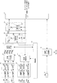
図1は、テレビ会議装置の外観図であり、図2は、テレビ会議装置の構成を示すブロック図である。テレビ会議装置は、スピーカSP1〜SP8、マイクM1〜M12、およびカメラ11を備えており、これらが近接して一体型の筐体としてモニタ2の上に設置されている。
A video conference apparatus according to an embodiment of the present invention will be described with reference to the drawings.
FIG. 1 is an external view of a video conference apparatus, and FIG. 2 is a block diagram showing a configuration of the video conference apparatus. The video conference apparatus includes speakers SP1 to SP8, microphones M1 to M12, and a
スピーカSP1〜SP8は、直線状に配列されてスピーカアレイを構成する。マイクM1〜M12も直線状に配列されてマイクアレイを構成する。なお、本実施形態では、スピーカの個数を8個、マイクの個数を12個とする例を示すが、配列個数はこの例に限定するものではない。また、スピーカ、マイクの配列間隔は等間隔でなくともよい。 The speakers SP1 to SP8 are arranged in a straight line to constitute a speaker array. The microphones M1 to M12 are also arranged linearly to constitute a microphone array. In the present embodiment, an example is shown in which the number of speakers is eight and the number of microphones is twelve, but the number of arrangements is not limited to this example. Moreover, the arrangement intervals of the speakers and microphones do not have to be equal.
図2に示すように、テレビ会議装置は、上記スピーカSP1〜SP8、マイクM1〜M12、およびカメラ11に加え、入出力I/F12、画像データ処理部13、制御部14、A/D変換部15、収音ビーム生成部16、信号選択回路17、予備フィルタ部18、エコーキャンセラ19、放音制御部20、およびD/A変換部21を備えている。
As shown in FIG. 2, in addition to the speakers SP1 to SP8, the microphones M1 to M12, and the
制御部14は、カメラ11、収音ビーム生成部16、信号選択回路17、予備フィルタ部18、および放音制御部20に接続されており、テレビ会議装置を統括的に制御する。例えばリモコン(図示せず)から入力されるユーザの操作に応じて、カメラ11の撮影範囲を設定したり、収音レベル、放音レベル等をコントロールする。また、後述する予備フィルタ部18の固定型フィルタ182のフィルタ係数を設定する。制御部14は、この固定型フィルタ182のフィルタ係数を複数記録したメモリを内蔵している。
The
入出力I/F12は、ネットワーク端子、オーディオ端子、ビデオ端子に接続されている。入出力I/F12は、これらの端子を介して相手先テレビ会議装置と音声、および映像を送受信する。ネットワーク端子を介して送受信する場合、ネットワーク通信データ形式からなる音声、および映像の各データを受信する。受信した映像データは画像データ処理部13に出力される。受信した音声データは、デジタル音声信号に変換されてエコーキャンセラ19、予備フィルタ部18、および放音制御部20に出力される。
The input / output I /
また、入出力I/F12は、画像データ処理部13から入力される映像データをネットワーク通信データ形式で相手先テレビ会議装置に送信し、エコーキャンセラ19から入力されるデジタル音声信号をネットワーク通信データ形式で相手先テレビ会議装置に送信する。
Further, the input / output I /
カメラ11は、自装置の前に居る会議者が含まれる範囲を撮像して、映像信号を画像データ処理部13に出力する。カメラ11がパン、チルト、ズーム機能を搭載している場合、撮影範囲は制御部14によって設定される。その他、撮影設定(コントラスト等)も制御部14によって設定される。
The
画像データ処理部13は、カメラ11から入力された映像信号を映像データ(圧縮データ)に変換し、これを入出力I/F12に出力する。また、入出力I/F12から入力された映像データをデコードして、映像信号としてモニタ2に出力する。
The image
マイクアレイの各マイクM1〜M12は、自装置の前に居る会議者(話者)の発声音を収音して収音音声信号を生成する。
A/D変換部15は、各マイクM1〜M12にそれぞれ対応して収音アンプ151、A/D変換器152を備えている。収音アンプ151は、収音音声信号を増幅し、A/D変換器152は、増幅された収音音声信号をデジタル音声信号に変換して、収音ビーム生成部16に出力する。
Each of the microphones M1 to M12 of the microphone array collects a voice of a conference person (speaker) in front of its own device and generates a collected voice signal.
The A /
収音ビーム生成部16は、A/D変換部15から入力された各デジタル音声信号に対して所定の遅延処理を行った後合成し、特定の領域から到来する音声を強調した信号である収音ビーム信号MB1〜MB4を生成する。収音ビーム信号MB1〜MB4は、図3に示すように、マイクM1〜M12が設置された長尺面側で当該長尺面に沿ってそれぞれに異なる所定幅の領域が収音ビーム領域(収音ビーム信号によって強調される特定の空間、方向)として設定されている。なお、収音ビームの数、領域の位置はこの例に限るものではない。制御部14が各デジタル音声信号の遅延量をコントロールすることで、収音ビーム領域を変更することができる。
The sound collection
信号選択回路17は、収音ビーム信号MB1〜MB4のうち最もレベルの高い信号を選択し、その収音ビーム信号をメイン収音ビーム信号MSとして予備フィルタ部18に出力する。また、選択した収音ビーム信号を制御部14に通知する。
The
図4は、信号選択回路17の主要構成を示すブロック図である。
信号選択回路17は、BPF(バンドパスフィルタ)171、全波整流回路172、ピーク検出回路173、レベル比較器174、および信号選択回路175を備えている。
FIG. 4 is a block diagram showing the main configuration of the
The
BPF171は、人の音声の主成分帯域を通過帯域とするバンドパスフィルタであり、収音ビーム信号MB1〜MB4を帯域通過フィルタ処理して、全波整流回路172に出力する。全波整流回路172は、収音ビーム信号MB1〜MB4を全波整流(絶対値化)し、ピーク検出回路173は、全波整流された収音ビーム信号MB1〜MB4のピーク検出を行い、ピーク値データPs1〜Ps4を出力する。レベル比較器174は、ピーク値データPs1〜Ps4を比較して、最も高いレベルのピーク値データPsに対応する収音ビーム信号を選択する選択指示データを信号選択回路175に与える。また、レベル比較器174は、最も高いレベルのピーク値データPsに対応する収音ビーム信号を選択する選択指示データを制御部14にも与える。信号選択回路175は、選択指示データが示す収音ビーム信号を選択し、メイン収音ビーム信号MSとして予備フィルタ部18に出力する。
これは、発話者が存在する収音領域に対応する収音ビーム信号の信号レベルが他の領域に対応する収音ビーム信号の信号レベルよりも高いことを利用している。
The
This utilizes the fact that the signal level of the sound collecting beam signal corresponding to the sound collecting region where the speaker is present is higher than the signal level of the sound collecting beam signal corresponding to the other region.
制御部14は、レベル比較器174から入力した選択指示データに基づいて、カメラ11の撮影設定を変更する。例えば、選択された収音ビーム信号の対応する領域の映像を撮影するように、カメラ11のパン、チルト、ズームを設定する。また、制御部14は、選択指示データに基づいて、予備フィルタ部18における固定型フィルタ182のフィルタ係数を設定する。
The
予備フィルタ部18は、LPF(ローパスフィルタ)181、固定型フィルタ182、およびポストプロセッサ183を備えている。LPF181は、低周波数帯域(例えば1kHz以下)を通過帯域とするローパスフィルタであり、エコーキャンセラ19から入力される信号、すなわち他の装置から入力される入力音声信号を低域通過フィルタ処理して、固定型フィルタ182に出力する。
The
固定型フィルタ182は、FIRフィルタであり、フィルタ係数は制御部14により設定される。制御部14は、スピーカ(SP1〜SP8)からマイク(M1〜M12)に至る音響伝達経路を擬似したフィルタ係数を設定する。フィルタ係数の詳細は図5を用いて後述する。固定型フィルタ182は、LPF181で低周波数帯域に帯域制限された入力音声信号をフィルタリングし、スピーカからマイクに至る回り込み音声を擬似した擬似信号を生成する。なお、固定型フィルタ182において、LPF181の機能を実現してもよい。
The fixed
予備フィルタ部18は、この擬似信号をポストプロセッサ183でメイン収音ビーム信号MSから減算することで、低周波数帯域の回り込み成分を除去した補正収音ビーム信号MSsを生成する。
The
エコーキャンセラ19は、適応型フィルタ191とポストプロセッサ192とを備えている。適応型フィルタ191は、入力音声信号に基づいて、スピーカアレイからマイクアレイに回り込む回帰音声信号を擬似した擬似回帰音信号を生成する。ポストプロセッサ192は、予備フィルタ部18から出力される補正収音ビーム信号MSsから擬似回帰音信号を減算して、出力音声信号として入出力I/F12に出力する。これによりエコー成分を消去する。また、出力音声信号は適応型フィルタ191に入力され、適応型フィルタ191は、入力された出力音声信号に基づいてエコー成分を消去するようにフィルタ係数を更新する。
The
放音制御部20は、入力音声信号に所定の遅延処理を行い、D/A変換部21における各D/Aコンバータ211に入力する。各D/Aコンバータ211は、入力された音声信号をアナログ音声信号に変換し、AMP212に入力する。AMP212は、アナログ音声信号を増幅してスピーカSP1〜SP8に入力し、スピーカSP1〜SP8は、音声を放音する。
The sound
放音制御部20は、スピーカアレイの各スピーカに入力する音声信号に遅延処理を行うことで、所定方向に強い指向性を有する放音ビームを形成することができる。また、所定位置に焦点を結ぶように放音ビームを形成することもできる。各スピーカは、焦点との実距離がそれぞれ異なるが、これらのスピーカを焦点から等距離に配列したようなタイミングで放音されるように音声信号を遅延すればよい。
The sound
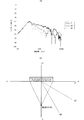
次に、図5は、回り込み信号のレベルを示す図である。同図(A)に示すグラフの横軸は周波数、縦軸はレベルを示す。同図(A)は、テレビ会議装置のスピーカアレイを用いて、前方の所定位置(同図Bに示す点)に焦点を結ぶ放音ビーム(ホワイトノイズ)を出力した場合のマイクアレイの収音レベル(メイン収音ビーム信号のレベル)を示している。同図(B)は、テレビ会議装置を上面側から見た場合のテレビ会議装置の収音方向、および放音の焦点位置を示している。同図(B)において、テレビ会議装置の中心位置を原点とし、紙面右側をX方向、左側を−X方向、上側を−Y方向、下側をY方向とする。また、X軸を0°とし、Y軸を90°とする。 Next, FIG. 5 is a diagram showing the level of the sneak signal. In the graph shown in FIG. 4A, the horizontal axis represents frequency and the vertical axis represents level. FIG. 6A shows the sound collection of the microphone array when a sound emitting beam (white noise) focused on a predetermined position in front (a point shown in FIG. 5B) is output using the speaker array of the video conference apparatus. The level (the level of the main collected beam signal) is shown. FIG. 5B shows the sound collection direction of the video conference device and the focal position of sound emission when the video conference device is viewed from the upper surface side. In FIG. 5B, the center position of the video conference apparatus is the origin, the right side of the paper is the X direction, the left side is the -X direction, the upper side is the -Y direction, and the lower side is the Y direction. Further, the X axis is 0 ° and the Y axis is 90 °.
スピーカアレイから放音される音声(ホワイトノイズ)は、地点A(0,42)に焦点を結ぶ。この地点A(0,42)は、テレビ会議装置の中心位置からY方向に42cmの地点を示す。同図(A)は、この地点Aに焦点を結ぶ放音ビームを出力しているときに、収音ビームを0°、30°、60°の方向に向けた場合の収音信号レベルを示している。同図(A)に示すように、どの角度についても300〜400Hz付近で回り込みレベルが最大となる。また、1kHz以上の帯域は角度によって周波数特性が大きく異なる。このため、予備フィルタ部18では、LPF181により1kHz以上をカットし、固定型フィルタ182では1kHz未満の帯域のみフィルタ係数を設定する。
The sound (white noise) emitted from the speaker array is focused on the point A (0, 42). This point A (0, 42) indicates a point of 42 cm in the Y direction from the center position of the video conference apparatus. FIG. 6A shows the sound collection signal level when the sound collection beam is directed in the directions of 0 °, 30 °, and 60 ° when the sound emission beam focused on the point A is output. ing. As shown in FIG. 5A, the wraparound level becomes maximum in the vicinity of 300 to 400 Hz for any angle. Further, the frequency characteristics of a band of 1 kHz or more vary greatly depending on the angle. For this reason, the
制御部14は、収音ビームの角度毎にフィルタ係数を記録している。すなわち、収音ビーム信号MB1〜MB4毎に、それぞれの収音角度に応じたフィルタ係数を記録している。フィルタ係数は、図5(A)に示した周波数特性の様に、回り込み音声を擬似した特性となる。
The
制御部14は、信号選択回路17のレベル比較器174から入力した選択指示データに基づいて、選択された収音ビーム信号に対応するフィルタ係数を固定型フィルタ182に設定する。これにより、補正収音ビーム信号MSsは、メイン収音ビーム信号MSから低周波数帯域(1kHz未満)の回り込み成分が低減された信号となる。したがって、エコーキャンセラ19では、回り込み成分が相対的に小さくなり、処理負担が減少する。
The
また、制御部14は、固定型フィルタ182に、予め定めた単一のフィルタ係数を設定しておいてもよい。例えば、図5(A)に示したグラフのうち、収音ビームが30°の方向である場合の周波数特性に対応したフィルタ係数を設定すればよい。
The
11−カメラ
SP1〜SP8−スピーカ
M1〜M12−マイク
11-Cameras SP1-SP8-Speakers M1-M12-Microphone
Claims (4)
前記収音部が収音した音声信号を信号処理し、収音信号を出力する収音信号処理部と、
外部から入力された入力信号を信号処理し、前記放音部に入力する入力信号処理部と、
前記入力信号を所定のフィルタ係数でフィルタリングする固定フィルタと、
前記放音部から前記収音部に至る音響伝達系の伝達関数を擬似した擬似フィルタ係数を記録し、擬似フィルタ係数を前記固定フィルタのフィルタ係数として設定するフィルタ係数設定部と、
前記収音信号から前記固定フィルタの出力信号を減算し、補正収音信号を生成するポストプロセッサと、
前記入力信号を適応型フィルタで処理した擬似エコー信号を、前記ポストプロセッサが生成した補正収音信号から減算する適応型エコーキャンセラと、
を備えたテレビ会議装置。 A video conferencing apparatus provided with a camera that shoots video, a sound emitting unit that emits sound, and a sound collecting unit that collects sound at close positions,
A sound collection signal processing unit that processes the sound signal collected by the sound collection unit and outputs the sound collection signal;
An input signal processing unit that processes an input signal input from the outside and inputs the signal to the sound emitting unit;
A fixed filter that filters the input signal with a predetermined filter coefficient;
A filter coefficient setting unit that records a pseudo filter coefficient simulating a transfer function of an acoustic transfer system from the sound emitting unit to the sound collecting unit, and sets a pseudo filter coefficient as a filter coefficient of the fixed filter;
A post processor that subtracts the output signal of the fixed filter from the collected sound signal to generate a corrected collected sound signal;
An adaptive echo canceller that subtracts a pseudo echo signal obtained by processing the input signal with an adaptive filter from a corrected sound pickup signal generated by the post processor;
Video conferencing equipment.
前記収音信号処理部は、前記複数のマイクが収音した音声信号を遅延処理して合成することにより、複数方向に収音指向性を有する複数の収音ビームを生成する収音ビーム生成回路と、前記複数の収音ビーム信号の音量レベルから話者方位を検出し、当該話者方位の収音ビーム信号を前記収音信号として出力する信号選択回路と、からなり、
前記フィルタ係数設定部は、前記収音ビーム生成回路が生成する収音ビーム信号の収音指向方向に対応する複数のフィルタ係数を記録し、
前記信号選択回路が選択した収音ビーム信号に対応するフィルタ係数を前記擬似フィルタ係数として前記固定フィルタに設定する請求項1に記載のテレビ会議装置。 The sound collection unit is composed of a microphone array in which a plurality of microphones are arranged,
The sound collecting signal processing unit generates a plurality of sound collecting beams having sound collecting directivities in a plurality of directions by delay processing and synthesizing sound signals collected by the plurality of microphones. And a signal selection circuit that detects a speaker orientation from the volume levels of the plurality of collected sound beam signals and outputs the collected sound beam signal of the speaker orientation as the collected sound signal,
The filter coefficient setting unit records a plurality of filter coefficients corresponding to the sound collection directing direction of the sound collection beam signal generated by the sound collection beam generation circuit,
The video conference apparatus according to claim 1, wherein a filter coefficient corresponding to the collected sound beam signal selected by the signal selection circuit is set in the fixed filter as the pseudo filter coefficient.
Priority Applications (4)
| Application Number | Priority Date | Filing Date | Title |
|---|---|---|---|
| JP2007130589A JP2008288785A (en) | 2007-05-16 | 2007-05-16 | Video conference apparatus |
| US12/600,400 US20100165071A1 (en) | 2007-05-16 | 2008-05-01 | Video conference device |
| CN200880016175A CN101682810A (en) | 2007-05-16 | 2008-05-01 | Video conference device |
| PCT/JP2008/058390 WO2008142979A1 (en) | 2007-05-16 | 2008-05-01 | Video conference device |
Applications Claiming Priority (1)
| Application Number | Priority Date | Filing Date | Title |
|---|---|---|---|
| JP2007130589A JP2008288785A (en) | 2007-05-16 | 2007-05-16 | Video conference apparatus |
Publications (1)
| Publication Number | Publication Date |
|---|---|
| JP2008288785A true JP2008288785A (en) | 2008-11-27 |
Family
ID=40031694
Family Applications (1)
| Application Number | Title | Priority Date | Filing Date |
|---|---|---|---|
| JP2007130589A Withdrawn JP2008288785A (en) | 2007-05-16 | 2007-05-16 | Video conference apparatus |
Country Status (4)
| Country | Link |
|---|---|
| US (1) | US20100165071A1 (en) |
| JP (1) | JP2008288785A (en) |
| CN (1) | CN101682810A (en) |
| WO (1) | WO2008142979A1 (en) |
Cited By (2)
| Publication number | Priority date | Publication date | Assignee | Title |
|---|---|---|---|---|
| US20090052684A1 (en) * | 2006-01-31 | 2009-02-26 | Yamaha Corporation | Audio conferencing apparatus |
| JP2011114769A (en) * | 2009-11-30 | 2011-06-09 | Nikon Corp | Imaging device |
Families Citing this family (33)
| Publication number | Priority date | Publication date | Assignee | Title |
|---|---|---|---|---|
| WO2007052726A1 (en) * | 2005-11-02 | 2007-05-10 | Yamaha Corporation | Teleconference device |
| WO2010044793A1 (en) * | 2008-10-15 | 2010-04-22 | Hewlett-Packard Development Company, L.P. | A conferencing system with a database of mode definitions |
| US8441515B2 (en) | 2009-09-17 | 2013-05-14 | Sony Corporation | Method and apparatus for minimizing acoustic echo in video conferencing |
| JP5593852B2 (en) * | 2010-06-01 | 2014-09-24 | ソニー株式会社 | Audio signal processing apparatus and audio signal processing method |
| CN102281425A (en) * | 2010-06-11 | 2011-12-14 | 华为终端有限公司 | Method and device for playing audio of far-end conference participants and remote video conference system |
| FR2977752A1 (en) * | 2011-07-06 | 2013-01-11 | Archos | ELECTRONIC DEVICE FOR GENERATING A VIDEO OUTPUT FLOW TO DISPLAY ON A TELEVISION SCREEN. |
| US8896651B2 (en) * | 2011-10-27 | 2014-11-25 | Polycom, Inc. | Portable devices as videoconferencing peripherals |
| SG190472A1 (en) * | 2011-11-25 | 2013-06-28 | Creative Tech Ltd | A speaker apparatus suitable for use with a computer |
| CN103124386A (en) * | 2012-12-26 | 2013-05-29 | 山东共达电声股份有限公司 | De-noising, echo-eliminating and acute directional microphone for long-distance speech |
| CN103475763A (en) * | 2013-09-26 | 2013-12-25 | 汉达尔通信技术(北京)有限公司 | Conversation echo canceling circuit of PSTN communication terminal |
| JP6349899B2 (en) * | 2014-04-14 | 2018-07-04 | ヤマハ株式会社 | Sound emission and collection device |
| US9565493B2 (en) | 2015-04-30 | 2017-02-07 | Shure Acquisition Holdings, Inc. | Array microphone system and method of assembling the same |
| US9554207B2 (en) | 2015-04-30 | 2017-01-24 | Shure Acquisition Holdings, Inc. | Offset cartridge microphones |
| US9530426B1 (en) * | 2015-06-24 | 2016-12-27 | Microsoft Technology Licensing, Llc | Filtering sounds for conferencing applications |
| US9747920B2 (en) * | 2015-12-17 | 2017-08-29 | Amazon Technologies, Inc. | Adaptive beamforming to create reference channels |
| US10367948B2 (en) | 2017-01-13 | 2019-07-30 | Shure Acquisition Holdings, Inc. | Post-mixing acoustic echo cancellation systems and methods |
| WO2018140618A1 (en) | 2017-01-27 | 2018-08-02 | Shure Acquisiton Holdings, Inc. | Array microphone module and system |
| US11523212B2 (en) | 2018-06-01 | 2022-12-06 | Shure Acquisition Holdings, Inc. | Pattern-forming microphone array |
| US11297423B2 (en) | 2018-06-15 | 2022-04-05 | Shure Acquisition Holdings, Inc. | Endfire linear array microphone |
| CN112889296B (en) | 2018-09-20 | 2025-01-10 | 舒尔获得控股公司 | Adjustable lobe shape for microphone arrays |
| US11109133B2 (en) | 2018-09-21 | 2021-08-31 | Shure Acquisition Holdings, Inc. | Array microphone module and system |
| CN111048093A (en) * | 2018-10-12 | 2020-04-21 | 深圳海翼智新科技有限公司 | Conference sound box, conference recording method, device, system and computer storage medium |
| US11558693B2 (en) | 2019-03-21 | 2023-01-17 | Shure Acquisition Holdings, Inc. | Auto focus, auto focus within regions, and auto placement of beamformed microphone lobes with inhibition and voice activity detection functionality |
| US11303981B2 (en) | 2019-03-21 | 2022-04-12 | Shure Acquisition Holdings, Inc. | Housings and associated design features for ceiling array microphones |
| WO2020191380A1 (en) | 2019-03-21 | 2020-09-24 | Shure Acquisition Holdings,Inc. | Auto focus, auto focus within regions, and auto placement of beamformed microphone lobes with inhibition functionality |
| US11445294B2 (en) | 2019-05-23 | 2022-09-13 | Shure Acquisition Holdings, Inc. | Steerable speaker array, system, and method for the same |
| EP3977449B1 (en) | 2019-05-31 | 2024-12-11 | Shure Acquisition Holdings, Inc. | Low latency automixer integrated with voice and noise activity detection |
| US11297426B2 (en) | 2019-08-23 | 2022-04-05 | Shure Acquisition Holdings, Inc. | One-dimensional array microphone with improved directivity |
| US12028678B2 (en) | 2019-11-01 | 2024-07-02 | Shure Acquisition Holdings, Inc. | Proximity microphone |
| US11552611B2 (en) | 2020-02-07 | 2023-01-10 | Shure Acquisition Holdings, Inc. | System and method for automatic adjustment of reference gain |
| US11706562B2 (en) | 2020-05-29 | 2023-07-18 | Shure Acquisition Holdings, Inc. | Transducer steering and configuration systems and methods using a local positioning system |
| WO2022165007A1 (en) | 2021-01-28 | 2022-08-04 | Shure Acquisition Holdings, Inc. | Hybrid audio beamforming system |
| CN114120950B (en) * | 2022-01-27 | 2022-06-10 | 荣耀终端有限公司 | Human voice shielding method and electronic equipment |
Family Cites Families (10)
| Publication number | Priority date | Publication date | Assignee | Title |
|---|---|---|---|---|
| JPH07107590A (en) * | 1993-09-30 | 1995-04-21 | Oki Electric Ind Co Ltd | Howling canceller |
| JP3541339B2 (en) * | 1997-06-26 | 2004-07-07 | 富士通株式会社 | Microphone array device |
| ATE394017T1 (en) * | 2004-01-07 | 2008-05-15 | Koninkl Philips Electronics Nv | AUDIO SYSTEM WITH PROVISIONS FOR FILTER COEFFICIENT COPY |
| JP3972921B2 (en) * | 2004-05-11 | 2007-09-05 | ソニー株式会社 | Voice collecting device and echo cancellation processing method |
| WO2006049260A1 (en) * | 2004-11-08 | 2006-05-11 | Nec Corporation | Signal processing method, signal processing device, and signal processing program |
| JP2006279565A (en) * | 2005-03-29 | 2006-10-12 | Yamaha Corp | Array speaker controller and array microphone controller |
| US8112272B2 (en) * | 2005-08-11 | 2012-02-07 | Asashi Kasei Kabushiki Kaisha | Sound source separation device, speech recognition device, mobile telephone, sound source separation method, and program |
| JP2007078545A (en) * | 2005-09-15 | 2007-03-29 | Yamaha Corp | Object detection system and voice conference system |
| JP2007096390A (en) * | 2005-09-27 | 2007-04-12 | Yamaha Corp | Speaker system and speaker apparatus |
| WO2007052726A1 (en) * | 2005-11-02 | 2007-05-10 | Yamaha Corporation | Teleconference device |
-
2007
- 2007-05-16 JP JP2007130589A patent/JP2008288785A/en not_active Withdrawn
-
2008
- 2008-05-01 CN CN200880016175A patent/CN101682810A/en active Pending
- 2008-05-01 US US12/600,400 patent/US20100165071A1/en not_active Abandoned
- 2008-05-01 WO PCT/JP2008/058390 patent/WO2008142979A1/en active Application Filing
Cited By (3)
| Publication number | Priority date | Publication date | Assignee | Title |
|---|---|---|---|---|
| US20090052684A1 (en) * | 2006-01-31 | 2009-02-26 | Yamaha Corporation | Audio conferencing apparatus |
| US8144886B2 (en) * | 2006-01-31 | 2012-03-27 | Yamaha Corporation | Audio conferencing apparatus |
| JP2011114769A (en) * | 2009-11-30 | 2011-06-09 | Nikon Corp | Imaging device |
Also Published As
| Publication number | Publication date |
|---|---|
| US20100165071A1 (en) | 2010-07-01 |
| WO2008142979A1 (en) | 2008-11-27 |
| CN101682810A (en) | 2010-03-24 |
Similar Documents
| Publication | Publication Date | Title |
|---|---|---|
| JP2008288785A (en) | Video conference apparatus | |
| JP2008312002A (en) | Television conference apparatus | |
| JP5028944B2 (en) | Audio conference device and audio conference system | |
| US9226070B2 (en) | Directional sound source filtering apparatus using microphone array and control method thereof | |
| JP5855571B2 (en) | Audio zoom | |
| KR101826274B1 (en) | Voice controlled audio recording or transmission apparatus with adjustable audio channels | |
| JP4929685B2 (en) | Remote conference equipment | |
| US20090147967A1 (en) | Conference apparatus | |
| US20140350935A1 (en) | Voice Controlled Audio Recording or Transmission Apparatus with Keyword Filtering | |
| JP2007274463A (en) | Remote conference apparatus | |
| WO2007058130A1 (en) | Teleconference device and sound emission/collection device | |
| JP2005057398A (en) | Speech unit | |
| KR101561843B1 (en) | Audio system for echo cancelation matched sound pickup area | |
| JP4411959B2 (en) | Audio collection / video imaging equipment | |
| JP2007274462A (en) | Video conference apparatus and video conference system | |
| CN106937009B (en) | Cascade echo cancellation system and control method and device thereof | |
| WO2011033924A1 (en) | Echo removal device, echo removal method, and program for echo removal device | |
| JP4479227B2 (en) | Audio pickup / video imaging apparatus and imaging condition determination method | |
| JP2007124140A (en) | Photographing device and communication conference system | |
| JP6353700B2 (en) | Two-way communication system between long-distance points and two-way communication method between long-distance points | |
| JP2007329753A (en) | Voice communication device and voice communication device | |
| JP2007060460A (en) | Teleconference system | |
| TWI846005B (en) | Video conference device and method for adjusting camera directions | |
| JP2006211156A (en) | Acoustic device | |
| JP4470413B2 (en) | Microphone / speaker integrated configuration / communication device |
Legal Events
| Date | Code | Title | Description |
|---|---|---|---|
| A621 | Written request for application examination |
Free format text: JAPANESE INTERMEDIATE CODE: A621 Effective date: 20100315 |
|
| A761 | Written withdrawal of application |
Free format text: JAPANESE INTERMEDIATE CODE: A761 Effective date: 20120330 |