JP2008263528A - Image information processing method and image information processing system - Google Patents
Image information processing method and image information processing system Download PDFInfo
- Publication number
- JP2008263528A JP2008263528A JP2007106213A JP2007106213A JP2008263528A JP 2008263528 A JP2008263528 A JP 2008263528A JP 2007106213 A JP2007106213 A JP 2007106213A JP 2007106213 A JP2007106213 A JP 2007106213A JP 2008263528 A JP2008263528 A JP 2008263528A
- Authority
- JP
- Japan
- Prior art keywords
- image
- camera
- image information
- depth
- subject
- Prior art date
- Legal status (The legal status is an assumption and is not a legal conclusion. Google has not performed a legal analysis and makes no representation as to the accuracy of the status listed.)
- Granted
Links
- 230000010365 information processing Effects 0.000 title claims abstract description 95
- 238000003672 processing method Methods 0.000 title claims abstract description 23
- 230000005540 biological transmission Effects 0.000 claims abstract description 56
- 238000005259 measurement Methods 0.000 claims description 9
- 238000000605 extraction Methods 0.000 claims description 7
- 239000000284 extract Substances 0.000 claims description 5
- 238000012545 processing Methods 0.000 abstract description 19
- 238000000034 method Methods 0.000 description 36
- 238000010586 diagram Methods 0.000 description 23
- 238000004364 calculation method Methods 0.000 description 16
- 238000012937 correction Methods 0.000 description 9
- 230000000052 comparative effect Effects 0.000 description 6
- 238000004891 communication Methods 0.000 description 3
- 238000006243 chemical reaction Methods 0.000 description 2
- 238000005520 cutting process Methods 0.000 description 2
- 238000001514 detection method Methods 0.000 description 2
- 238000009826 distribution Methods 0.000 description 2
- 230000000694 effects Effects 0.000 description 2
- 238000003860 storage Methods 0.000 description 2
- 230000006835 compression Effects 0.000 description 1
- 238000007906 compression Methods 0.000 description 1
- 230000007812 deficiency Effects 0.000 description 1
- 230000012447 hatching Effects 0.000 description 1
- 230000001678 irradiating effect Effects 0.000 description 1
- 238000004519 manufacturing process Methods 0.000 description 1
- 239000000203 mixture Substances 0.000 description 1
- 230000000737 periodic effect Effects 0.000 description 1
- 230000002093 peripheral effect Effects 0.000 description 1
Images


Landscapes
- Testing, Inspecting, Measuring Of Stereoscopic Televisions And Televisions (AREA)
Abstract
【課題】複数のカメラ画像に基づく任意視点の画像を生成する際に、送信側システムにおける情報処理量を過大にせず、受信側システムとして処理能力の低い機器が使用でき、システム全体の情報処理量を低減できる画像情報処理方法及びシステムを提供する。
【解決手段】送信側システム10は、複数のカメラ画像を取得し、複数のカメラ画像に対応する複数の奥行きマップを生成し、複数のカメラ画像及び複数の奥行きマップを符号化して送信し、受信側システム30は、複数のカメラ画像及び複数の奥行きマップを受信して復号化し、複数のカメラ画像及び複数の奥行きマップを用いて、カメラ画像の間の補間画像を計算して、カメラ画像と補間画像とからなる光線空間を生成し、光線空間から表示画像を切り出して出力する。
【選択図】図7[PROBLEMS] To generate an arbitrary viewpoint image based on a plurality of camera images without using an excessive amount of information processing in a transmission side system and allowing a device with low processing capability to be used as a reception side system. An image information processing method and system capable of reducing image quality are provided.
A transmission system acquires a plurality of camera images, generates a plurality of depth maps corresponding to the plurality of camera images, encodes and transmits the plurality of camera images and the plurality of depth maps, and receives them. The side system 30 receives and decodes the plurality of camera images and the plurality of depth maps, calculates an interpolation image between the camera images using the plurality of camera images and the plurality of depth maps, and interpolates the camera image and the interpolation. A light space composed of an image is generated, and a display image is cut out from the light space and output.
[Selection] Figure 7
Description
本発明は、複数のカメラ画像に基づいて実際にカメラが存在しない視点(仮想カメラ)から見た自由視点画像を生成するための画像情報処理方法及び画像情報処理システムに関し、特に、複数のカメラ画像を取得する送信側システム及び自由視点画像を表示する受信側システムにおける画像情報処理に関する。 The present invention relates to an image information processing method and an image information processing system for generating a free viewpoint image viewed from a viewpoint (virtual camera) where no camera actually exists based on a plurality of camera images, and in particular, a plurality of camera images. The present invention relates to image information processing in a transmission-side system that acquires image and a reception-side system that displays a free viewpoint image.
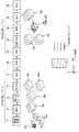
見る者があたかもその場にいるかのように、自由に視点を変えて3次元シーンを見ることのできる自由視点テレビ(Free viewpoint TV:FTV)が提案されている(例えば、非特許文献1及び2参照)。図1は、FTVシステムの基本的な構成を概念的に示す図である。図1に示されるFTVシステムは、複数のカメラによる撮影(ステップST1)、離散的にしか存在しないカメラ画像の間に画像を補間する補間処理(ステップST2又は2a)、及び入力された視点(仮想カメラ)から見た画像の切り出し及び表示(ステップST4及びST5)を行う。FTVシステムでは、3次元実空間に存在する被写体101の画像情報を複数のカメラ(図1には、符号1021〜1025の5台を示すが、実際にはより多くのカメラが用いられる。)によって取得し、取得された複数のカメラ画像(図1には、符号1031〜1035の5つの画像を示すが、実際にはより多くの画像が用いられる。)を光線空間103に配列し、FTV信号とする。なお、図において、xは、水平視野方向、yは、垂直視野方向、u(=tanθ)は、視域方向を示す。
Free viewpoint TV (FTV) has been proposed that allows a viewer to freely change the viewpoint and view a three-dimensional scene as if the viewer is on the spot (for example, Non-Patent
光線空間法では、3次元実空間の1本の光線を、それを表すパラメータを座標とする多次元空間の1点で表す。この仮想的な多次元空間を光線空間(Ray Space)という。光線空間全体は、3次元空間のすべての光線を過不足なく表現する。光線空間は、多くの視点から撮影された画像を集めることによって作られる。光線空間の点の値は、画像の画素値と同じであるから、画像から光線空間への変換は、単なる座標変換である。図2(a)に示されるように、実空間中の基準面106を通過する光線107は通過位置(x,y)と通過方向(θ,φ)の4つのパラメータによって一意に表現することができる。図2(a)において、Xは、3次元実空間における水平方向の座標軸であり、Yは、垂直方向の座標軸であり、Zは、奥行き方向の座標軸である。また、θは、基準面106の法線に対する水平方向の角度、すなわち、基準面106に対する水平方向の出射角であり、φは、基準面106の法線に対する垂直方向の角度、すなわち、基準面106に対する垂直方向の出射角である。これにより、この3次元実空間内の光線情報を輝度f(x,y,θ,φ)と表すことができる。ここでは、説明を分かりやすくするために、垂直方向の視差(角度φ)を無視する。図2(a)に示されるように、基準面106に向けて、且つ、水平に配置された多数のカメラで撮影された画像は、図2(b)に示されるように、x,y,u(=tanθ)の軸を持つ3次元空間において、点線で描かれる断面1031〜1035に位置していることになる。図2(b)に示される光線空間103から任意の面を切り取ることによって、実空間における水平方向の任意の視点から見た画像を生成することが可能となる。例えば、図3(a)に示される光線空間103から断面103aを切り出すと、図3(b)に示されるような画像がディスプレイに表示され、図3(a)に示される光線空間103から断面103bを切り出すと、図3(c)に示されるような画像がディスプレイに表示される。また、光線空間103に配列された画像(断面1031〜1035)の間にはデータがないため、これを補間によって作る。なお、補間は、光線空間の全体についてではなく、必要な部分についてのみ行う場合もある。
In the ray space method, one ray in a three-dimensional real space is represented by one point in a multidimensional space with parameters representing the coordinates as coordinates. This virtual multidimensional space is called a ray space. The entire ray space expresses all rays in the three-dimensional space without excess or deficiency. Ray space is created by collecting images taken from many viewpoints. Since the value of the point in the light space is the same as the pixel value of the image, the conversion from the image to the light space is a simple coordinate conversion. As shown in FIG. 2A, the
図4は、送信側システム210と受信側システム230とから構成される従来の画像情報処理システムの構成及び動作を示す図である。図4に示されるように、送信側システム210は、被写体101を複数のカメラ211aで撮影することによって複数のカメラ画像210aを取得する画像取得部211と、取得された複数のカメラ画像210aを補正する補正部212と、補正されたカメラ画像210bを符号化する符号化部(エンコーダ)213と、符号化されたカメラ画像210cとカメラパラメータをインターネットなどの伝送手段220を介して送信する送信部214とを有している。また、受信側システム230は、送信側システム210から送信されたカメラ画像210cとカメラパラメータを受信する受信部231と、受信されたカメラ画像210cを復号化する復号化部(デコーダ)232と、復号化されたカメラ画像230aを用いて光線空間230bを生成する画像生成(View Generation)部233と、光線空間230bから表示画像を切り出す抽出部234と、切り出された表示画像230cを表示する表示部235と有している。
FIG. 4 is a diagram illustrating the configuration and operation of a conventional image information processing system including a transmission side system 210 and a reception side system 230. As illustrated in FIG. 4, the transmission-side system 210 corrects the acquired plurality of
図5(a)〜(c)は、従来の画像情報処理システム又は3Dサービスシステムの具体例を示すブロック図である。図5(a)に示されるインターネットを用いたダウンロード/パッケージサービスにおいては、送信側システムのデジタルアーカイブス241を伝送/パッケージ手段242を介して受信側の複数のユーザのシステムに送信し、各ユーザのシステムがデコーダ243による復号化、画像生成部244による光線空間の生成、及び表示部245による自由視点画像(2D画像又は3D画像)の表示を行う。ダウンロード/パッケージサービスにおいては、リアルタイム性はあまり要求されない。図5(b)に示される放送サービスにおいては、送信側の画像取得部251でカメラ画像を取得し、補正部252でカメラ画像を補正し、エンコーダ253で符号化した画像を伝送手段254によって伝送し、受信側の複数のユーザのシステムにおいて、デコーダ255が受信画像を復号化し、画像生成部256によって光線空間を生成し、自由視点画像の表示を行う。放送サービスにおいては、ダウンロード/パッケージサービスよりはリアルタイム性が要求されるが、完全なリアルタイム性までは要求されない。図5(c)に示される通信サービスにおいては、画像取得部261又は271、補正部262又は272、及びエンコーダ263又は273を有する送信側システムから、伝送手段264を介して符号化画像を伝送し、デコーダ265又は275、画像生成部266又は276、及び表示部267又は277を有する受信側システムが復号化、画像生成、及び自由視点画像の表示を行う。通信サービスにおいては、高いリアルタイム性が要求される。
FIGS. 5A to 5C are block diagrams illustrating a specific example of a conventional image information processing system or 3D service system. In the download / package service using the Internet shown in FIG. 5A, the
図4又は図5(a)〜(c)に示されるシステムにおいては、カメラ画像から自由視点画像を生成するための画像生成処理(図4の画像生成部233による処理、図5(a)の画像生成部244による処理、図5(b)の画像生成部256による処理、図5(c)の画像生成部266及び276による処理)をすべて受信側システムで行っている。自由視点画像の生成にはシーンの奥行き情報である奥行きマップ(Depth Map)の算出プロセスと、この奥行きマップを用いた光線空間の補間(interpolation)プロセスが含まれる。このため、複数のカメラ画像(輝度信号)のみを受信側システムに伝送した場合には、受信側システムで複数のカメラ画像から奥行きマップを算出する必要が生じる。しかし、奥行きマップの算出処理には、非常に計算能力の高い装置が必要であり、ユーザ側機器である受信側システム230に、自由視点画像を生成するための高い計算能力を持たせることは、コスト面から難しいという問題がある。
In the system shown in FIG. 4 or FIGS. 5A to 5C, image generation processing for generating a free viewpoint image from a camera image (processing by the
このため、複数のカメラ画像から自由視点画像を生成するための処理における、奥行きマップの算出プロセス及び補間プロセスを送信側システムで行い、受信側システムは光線空間から表示画像を切り出す処理を行うシステムも考えられる。図6は、このような画像情報処理システムの構成及び動作を示す図である。図6に示されるように、送信側システム310は、被写体101を複数のカメラ311aで撮影することによって複数のカメラ画像310aを取得する画像取得部311と、撮影された複数のカメラ画像310aを補正する補正部312と、補正されたカメラ画像310bから補間画像を生成して補間された光線空間310cを生成する画像生成部313と、光線空間310cの情報を符号化する符号化部314と、符号化された光線空間情報を伝送手段320を介して送信する送信部315とを有している。また、受信側システム330は、送信側システム310から送信された光線空間310cの情報を受信する受信部331と、受信された情報を復号化する復号化部332と、復号化された情報を用いて光線空間310cを生成する画像生成部332と、光線空間310cから表示画像を切り出す抽出部333と、抽出された表示画像310dを表示する表示部334と有している。
For this reason, in the process for generating a free viewpoint image from a plurality of camera images, the depth map calculation process and the interpolation process are performed in the transmission side system, and the reception side system performs a process of cutting out the display image from the light space. Conceivable. FIG. 6 is a diagram showing the configuration and operation of such an image information processing system. As illustrated in FIG. 6, the transmission-
しかし、図6に示される画像情報処理システムの送信側システム310で光線空間を作成する場合には、受信側に存在する多数のユーザのすべての要望に対応できるようにするため、離散的にしか存在しない複数のカメラ画像の間を埋め尽くすように、極めて多くの補間画像を形成する必要がある。このため、送信側システム310における情報処理量が膨大になり、送信者、例えば、放送事業者、に多大なコストを強いるという問題がある。
However, when the light space is created by the
そこで、本発明は、上記従来技術の課題を解決するためになされたものであり、その目的は、複数のカメラ画像に基づく任意視点の画像を生成する画像情報処理において、送信側システムにおける情報処理量を抑制でき、かつ、受信側システムとして計算能力の低い機器を使用でき、かつ、システム全体の情報処理量を低減することができる画像情報処理方法及び画像情報処理システムを提供することにある。 Accordingly, the present invention has been made to solve the above-described problems of the prior art, and an object of the present invention is to perform information processing in a transmission-side system in image information processing that generates an image of an arbitrary viewpoint based on a plurality of camera images. An object of the present invention is to provide an image information processing method and an image information processing system capable of reducing the amount of information, using a device with low calculation capability as a receiving system, and reducing the information processing amount of the entire system.
本発明の画像情報処理方法は、送信側システムと受信側システムとを有する画像情報処理システムにおける方法であって、前記送信側システムが、被写体を複数のカメラで撮影することによって複数のカメラ画像を取得するステップと、前記送信側システムが、撮影された前記複数のカメラ画像に対応し、前記カメラに入射する光線を出す前記被写体の部分の方向と距離を含む前記被写体の奥行き情報から構成される奥行きマップを生成するステップと、前記送信側システムが、前記カメラ画像及び前記奥行きマップを符号化するステップと、前記送信側システムが、符号化された前記カメラ画像及び前記奥行きマップを送信するステップと、前記受信側システムが、前記送信側システムから送信された前記カメラ画像及び前記奥行きマップを受信するステップと、前記受信側システムが、受信された前記カメラ画像及び前記奥行きマップを復号化するステップと、前記受信側システムが、復号化された前記カメラ画像及び前記奥行きマップを用いて、前記カメラ画像の間の補間画像を計算して、前記カメラ画像と前記補間画像とからなる光線空間情報を生成するステップと、前記受信側システムが、前記光線空間情報から表示画像を抽出して出力するステップとを有することを特徴としている。 An image information processing method of the present invention is a method in an image information processing system having a transmission side system and a reception side system, and the transmission side system captures a plurality of camera images by photographing a subject with a plurality of cameras. The step of obtaining, and the transmission side system includes depth information of the subject including the direction and distance of the portion of the subject corresponding to the plurality of photographed camera images and emitting light incident on the camera Generating a depth map; the transmitting system encoding the camera image and the depth map; and the transmitting system transmitting the encoded camera image and the depth map. The camera image and the depth map transmitted from the transmission side system by the reception side system Receiving, the receiving system decoding the received camera image and the depth map, and the receiving system using the decoded camera image and the depth map, A step of calculating an interpolated image between camera images and generating light space information comprising the camera image and the interpolated image; and the receiving system extracting and outputting a display image from the light space information. And a step.
また、本発明の画像情報処理システムは、送信側システムと受信側システムとを有する画像情報処理システムであって、前記送信側システムが、被写体を複数のカメラで撮影することによって複数のカメラ画像を取得する複数のカメラと、撮影された前記複数のカメラ画像に対応し、前記カメラに入射する光線を出す前記被写体の部分の方向と距離を含む前記被写体の奥行き情報から構成される奥行きマップを生成する奥行きサーチ部と、前記カメラ画像及び前記奥行きマップを符号化する符号化部と、符号化された前記カメラ画像及び前記奥行きマップを送信する送信部とを有し、前記受信側システムが、前記送信側システムから送信された前記カメラ画像及び前記奥行きマップを受信する受信部と、受信された前記カメラ画像及び前記奥行きマップを復号化する復号化部と、復号化された前記カメラ画像及び前記奥行きマップを用いて、前記カメラ画像の間の補間画像を計算して、前記カメラ画像と前記補間画像とからなる光線空間情報を生成する補間部と、前記光線空間情報から表示画像を抽出して出力する抽出部とを有することを特徴としている。 The image information processing system of the present invention is an image information processing system having a transmission side system and a reception side system, and the transmission side system captures a plurality of camera images by photographing a subject with a plurality of cameras. Generates a depth map consisting of a plurality of cameras to be acquired and depth information of the subject including the direction and distance of the portion of the subject that emits light incident on the camera, corresponding to the captured camera images A depth search unit, an encoding unit that encodes the camera image and the depth map, and a transmission unit that transmits the encoded camera image and the depth map. A receiving unit that receives the camera image and the depth map transmitted from the transmission-side system; the received camera image and the depth map; A decoding unit that decodes a map, and using the decoded camera image and the depth map, an interpolation image between the camera images is calculated, and a light beam composed of the camera image and the interpolation image An interpolation unit that generates spatial information and an extraction unit that extracts and outputs a display image from the light space information are characterized.
本発明の画像情報処理方法及び画像情報処理システムにおいては、複数のカメラ画像から各カメラに対応する奥行きマップを計算する処理を送信側システムで行い、複数のカメラ画像と複数の奥行きマップを用いて、光線空間に画像を補間する処理を受信側システムで行っている。このように、情報処理量の大きい奥行きマップの生成処理を送信側システムが行うことによって、受信側システムに要求される計算能力を低くすることができ、受信者のコスト負担を低減することができる。 In the image information processing method and the image information processing system according to the present invention, a process for calculating a depth map corresponding to each camera from a plurality of camera images is performed on the transmission side system, and a plurality of camera images and a plurality of depth maps are used. The receiving side system performs the process of interpolating the image in the light space. As described above, when the transmission-side system performs the depth map generation processing with a large amount of information processing, the calculation capability required for the reception-side system can be reduced, and the cost burden on the receiver can be reduced. .
また、複数のカメラ画像と複数の奥行きマップを用いて光線空間を補間する処理は、送信側システムで行う場合には、複数のカメラ画像の間の全領域について行う必要があるが、受信側システムで行う場合には、ユーザが指定した領域に関係する部分についてのみ行えばよい。したがって、本発明の画像情報処理方法及び画像情報処理システムによれば、補間処理を行う受信側システムに要求される計算能力は低く、受信者のコスト負担を大きく増加させることはない。 In addition, when the process of interpolating the light space using a plurality of camera images and a plurality of depth maps is performed in the transmission side system, it is necessary to perform the entire region between the plurality of camera images. In this case, it is sufficient to perform only the portion related to the area designated by the user. Therefore, according to the image information processing method and the image information processing system of the present invention, the calculation capability required for the receiving system that performs the interpolation processing is low, and the cost burden on the receiver is not greatly increased.
さらに、複数のカメラ画像と奥行きマップを用いて光線空間を補間する処理は、送信側システムで行う場合には、複数のカメラ画像の間の全領域について行う必要があるが、受信側システムで行う場合には、ユーザが指定した領域に関係する部分についてのみ行えばよい。このため、補間処理を受信側システムで行う本発明の画像情報処理方法及び画像情報処理システムによれば、画像生成処理のすべてを送信側システムで行う場合に比べ、システム全体の情報処理量を削減することができ、結果的に、計算コストを削減することができる。 Furthermore, when the process of interpolating the light space using the plurality of camera images and the depth map is performed on the transmission side system, it is necessary to perform the process on the entire area between the plurality of camera images. In this case, it is only necessary to perform a portion related to the area designated by the user. For this reason, according to the image information processing method and the image information processing system of the present invention in which the interpolation process is performed in the receiving system, the information processing amount of the entire system is reduced as compared with the case where all the image generation processes are performed in the transmitting system. As a result, the calculation cost can be reduced.
《1.第1の実施形態》
〈1−1.第1の実施形態の画像情報処理システムの構成及び動作〉
図7は、送信側(sender)システム10と受信側(receiver)システム30とから構成される本発明の第1の実施形態の画像情報処理システムの構成及び動作を示す図である。図7の画像情報処理システムは、任意の視点から見た2次元画像を表示するFTVシステムであるが、三次元(3D)画像を表示する3D表示システムとすることもできる。
<< 1. First Embodiment >>
<1-1. Configuration and Operation of Image Information Processing System According to First Embodiment>
FIG. 7 is a diagram showing the configuration and operation of the image information processing system according to the first embodiment of the present invention, which is composed of a
図7に示される画像情報処理システムは、送信側システム10と受信側システム30とを有するシステムである。送信側システム10は伝送(transmission)手段20を介して受信側システム30に情報を送信する。伝送手段20は、例えば、インターネット、放送設備、通信設備などであるが、信号を伝送できる手段であれば何であってもよい。また、伝送手段20は、必要に応じて、情報を保持する記憶手段(storage)を備えたものであってもよい。
The image information processing system shown in FIG. 7 is a system having a
図7に示されるように、送信側システム10は、被写体101を複数のカメラ11aで撮影することによって複数のカメラ画像10aを取得する画像取得部11と、撮影された複数のカメラ画像10aを補正する補正部12と、補正された複数のカメラ画像10bに対応する複数の奥行きマップ10dを生成する奥行きサーチ部13と、複数のカメラ画像10b及び各カメラ画像に対応する複数の奥行きマップを符号化する符号化部14と、符号化されたカメラ画像10c、奥行きマップ10d、及び複数のカメラ11aに関するカメラパラメータを伝送手段20を介して送信する送信部15とを有している。補正部12は、複数のカメラ11aが、例えば、1列に等間隔で並んでいない場合や同じ方向を向いていない場合に、カメラ画像を補正して、複数のカメラが1列に等間隔で並び且つ同じ方向を向いていると見なせるように、カメラ画像10aを補正する。奥行きマップ10dは、カメラに入射する光線を出す被写体101の各部分の方向と距離を含む被写体101の奥行き情報から構成される。
As shown in FIG. 7, the transmission-
また、図7に示されるように、受信側システム30は、送信側システム10から伝送手段20を介して送信されたカメラ画像10c、奥行きマップ10d、及びカメラパラメータを受信する受信部31と、受信されたカメラ画像10c及び奥行きマップ10dを復号化する復号化部32と、復号化されたカメラ画像10e、奥行きマップ10f、及びカメラパラメータを用いて、カメラ画像の間の補間画像を計算して、カメラ画像からなる光線空間に補間画像を補間する補間部33と、補間後の光線空間10gから表示画像を切り出す抽出部34と、切り出された表示画像10hを1台又は複数台のディスプレイに表示する表示部35と有している。
As shown in FIG. 7, the receiving system 30 includes a receiving
<本発明の画像情報処理システムの動作(本発明の画像情報処理方法)>
本発明の第1の実施形態においては、図7に示されるように、送信側システム10は、被写体101を複数のカメラ11aで撮影することによって複数のカメラ画像10aを取得し、撮影された複数のカメラ画像10aを必要に応じて補正し、複数のカメラ画像10bに対応する複数の奥行きマップを生成し、複数のカメラ画像10b及び複数の奥行きマップを符号化し、カメラ画像10c、奥行きマップ10d、及びカメラパラメータを伝送手段20を介して送信する。
<Operation of Image Information Processing System of the Present Invention (Image Information Processing Method of the Present Invention)>
In the first embodiment of the present invention, as shown in FIG. 7, the transmission-
また、図7に示されるように、受信側システム30は、送信側システム10から伝送手段20を介して送信されたカメラ画像10c、奥行きマップ10d、及びカメラパラメータを受信し、受信されたカメラ画像10c及び奥行きマップ10dを復号化し、復号化されたカメラ画像10e、奥行きマップ10f、及びカメラパラメータを用いて、カメラ画像の間の補間画像を計算して、カメラ画像からなる光線空間に補間画像を補間し、補間後の光線空間10gから表示画像を切り出し、切り出された表示画像10hを表示する。
Also, as shown in FIG. 7, the receiving system 30 receives the
図8は、本発明の第1の実施形態の画像情報処理システム(図7)及び従来の画像情報処理システム(図4、図6)における送信側システムから送信される情報を示す図である。図4に示される従来の画像情報処理システム(比較例)の場合には、送信側システム210から送信される画像はカメラパラメータと複数のカメラ画像210cである。図6に示される従来の画像情報処理システム(比較例)の場合には、送信側システム310から送信される画像は光線空間情報310cである。これに対し、図7に示される本発明の画像情報処理システムにおいては、送信側システム10から送信される画像はカメラパラメータと複数のカメラ画像10cと各カメラの奥行きマップ10dである。
FIG. 8 is a diagram showing information transmitted from the transmission-side system in the image information processing system (FIG. 7) and the conventional image information processing system (FIGS. 4 and 6) according to the first embodiment of the present invention. In the case of the conventional image information processing system (comparative example) shown in FIG. 4, images transmitted from the transmission-side system 210 are camera parameters and a plurality of
図9は、本発明の第1の実施形態の画像情報処理システム(図7)における複数のカメラ画像と複数の奥行きマップを示す図である。図9において、Nは正の整数であり、kはN以下の正の整数である。図9において、1、2、…、k−1、k、k+1、…、Nは、画像取得部(図7の符号11)の複数のカメラのカメラ番号である。また、I1、I2、…、Ik−1、Ik、Ik+1、…、INは、複数のカメラ画像を示し、D1、D2、…、Dk−1、Dk、Dk+1、…、DNは、各カメラに対応する奥行きマップを示す。図9に示されるカメラ画像I1、I2、…、Ik−1、Ik、Ik+1、…、INのそれぞれは1枚の画像で(例えば、長方形)あるが、図9においては、カメラ画像を図9が描かれた紙面に垂直に並べている場合を示している。また、図9に示される奥行きマップD1、D2、…、Dk−1、Dk、Dk+1、…、DNのそれぞれは、カメラ画像と同様に1枚の画像(例えば、長方形)として表すことができるが、図9においては、奥行きマップを図9が描かれた紙面に垂直に並べている場合を示している。
FIG. 9 is a diagram showing a plurality of camera images and a plurality of depth maps in the image information processing system (FIG. 7) according to the first embodiment of the present invention. In FIG. 9, N is a positive integer, and k is a positive integer equal to or less than N. 9, 1, 2,..., K-1, k, k + 1,..., N are camera numbers of a plurality of cameras of the image acquisition unit (
図10は、1枚の奥行きマップを明るさの違いで表示した例を示す図である。図10において、明るい部分(白い部分)は近い部分であり、暗く(黒く)なるほど遠い部分を示す。送信側システム10から送信されるカメラ画像I1、I2、…、Ik−1、Ik、Ik+1、…、INがN枚である場合には、送信側システム10から送信される奥行きマップD1、D2、…、Dk−1、Dk、Dk+1、…、DNもN枚となる。
FIG. 10 is a diagram illustrating an example in which one depth map is displayed with a difference in brightness. In FIG. 10, a bright part (white part) is a close part, and a dark part (black) shows a far part. When the camera images I 1 , I 2 ,..., I k−1 , I k , I k + 1 ,..., N transmitted from the
図11は、図4に示される従来の画像情報処理システム(比較例)の送信側システム210及び受信側システム230における情報処理プロセスを示す図である。図11において、1、2、…、k−1、k、k+1、…、Nは、画像取得部(図4の符号211)の複数のカメラのカメラ番号である。また、I1、I2、…、Ik−1、Ik、Ik+1、…、INは、複数のカメラ画像を示し、D1、D2、…、Dk−1、Dk、Dk+1、…、DNは、各カメラに対応する奥行きマップを示す。図11に示されるカメラ画像及び奥行きマップのそれぞれは、カメラ画像と同様に1枚の画像(例えば、長方形)として表すことができるが、図11においては、奥行きマップを図11が描かれた紙面に垂直に並べている場合を示している。図11に示されるように、図4に示される画像情報処理システム(比較例)においては、奥行きサーチ、及び奥行きマップD1、D2、…、Dk−1、Dk、Dk+1、…、DNの生成を、受信側システム230が行っている。
FIG. 11 is a diagram showing an information processing process in the transmission side system 210 and the reception side system 230 of the conventional image information processing system (comparative example) shown in FIG. 11, 1, 2,..., K-1, k, k + 1,..., N are camera numbers of a plurality of cameras of the image acquisition unit (
図12は、図6に示される従来の画像情報処理システム(比較例)の送信側システム310及び受信側システム330における情報処理プロセスを示す図である。図12において、1、2、…、k−1、k、k+1、…、Nは、画像取得部(図6の符号311)の複数のカメラのカメラ番号である。また、I1、I2、…、Ik−1、Ik、Ik+1、…、INは、複数のカメラ画像を示し、D1、D2、…、Dk−1、Dk、Dk+1、…、DNは、各カメラに対応する奥行きマップを示す。図12に示されるカメラ画像及び奥行きマップのそれぞれは、カメラ画像と同様に1枚の画像として表すことができるが、図12においては、奥行きマップを図12が描かれた紙面に垂直に並べている場合を示している。図12に示されるように、図6に示される画像情報処理システム(比較例)においては、奥行きサーチ、及び奥行きマップD1、D2、…、Dk−1、Dk、Dk+1、…、DNの生成、光線空間の生成を送信側システム310が行っている。
FIG. 12 is a diagram showing an information processing process in the
図13は、本発明の第1の実施形態の画像情報処理システムの送信側システム10及び受信側システム30における情報処理プロセスを示す図である。図13において、1、2、…、k−1、k、k+1、…、Nは、画像取得部(図7の符号11)の複数のカメラのカメラ番号である。また、I1、I2、…、Ik−1、Ik、Ik+1、…、INは、複数のカメラ画像を示し、D1、D2、…、Dk−1、Dk、Dk+1、…、DNは、各カメラに対応する奥行きマップを示す。図13に示されるカメラ画像及び奥行きマップのそれぞれは、カメラ画像と同様に1枚の画像(例えば、長方形)として表すことができるが、図13においては、奥行きマップを図13が描かれた紙面に垂直に並べている場合を示している。図13に示されるように、本発明の第1の実施形態の画像情報処理システムにおいては、奥行きサーチ、及び奥行きマップD1、D2、…、Dk−1、Dk、Dk+1、…、DNの生成を送信側システム10が行い、補間画像の生成及び補間された光線空間からの表示画像の切り出しを受信側システム30が行っている。
FIG. 13 is a diagram illustrating an information processing process in the transmission-
〈1−2.画像生成処理〉
図14は、実際のカメラで取得されたカメラ画像から任意視点の画像を生成するプロセスを示す図である。図14において、401〜405は、直線上に1列に同じ方向を向けて配列したカメラであり、411は、実際には存在しない仮想カメラ(ユーザーが指定して視点位置)である。カメラ401〜405は、カメラ401〜405を通る光線を撮影するが、隣り合うカメラ間を通る光線は撮影していない。そこで、ユーザが見たいところ、すなわち、隣り合うカメラ間に仮想カメラ411を置く。実際のカメラ(図14においては、カメラ402、403)を通る光線から、補間して仮想カメラ411を通る光線を作る。しかし、カメラ401〜405を通る光線はどの方向から来た光線であるかはわかるが、どの位置から来た光線かは、わからない。そこで、例えば、図14に示されるカメラ402と403を用いて、被写体412の奥行きをサーチする。この奥行きサーチに際しては、物体表面のある点からの光はどの方向にも同じ強度であるということ(ランベルト反射)を前提とすると、カメラ402の撮影点(被写体上の部分)とカメラ403の撮影点(被写体上の部分)の輝度がマッチングする位置を探し、マッチングした位置を物体の表面と推定する。このとき、カメラ402とカメラ403の間隔は既知であり、マッチング位置からの光線がカメラ402に入射する角度とマッチング位置からの光線がカメラ403に入射する角度も判るので、マッチング位置までの距離を計算することができる。このようにして物体の奥行きを推定できた後に、仮想カメラ411から見た画像を推定して補間画像を生成する。
<1-2. Image generation processing>
FIG. 14 is a diagram illustrating a process for generating an image of an arbitrary viewpoint from a camera image acquired by an actual camera. In FIG. 14,
図15は、奥行きと視差との関係を示す図である。光線空間における補間画像は、生成すべきカメラ位置でのシーンの奥行きを求めることができれば、生成可能となる。ここで、奥行きと視差との幾何学的な関係を説明する。簡単のために高さ方向を考慮しない2次元平面で考える。左右のカメラをカメラ(camera)Lとカメラ(camera)Rとする。光線源Mの奥行きをDと仮定する。このとき、この光線源Mが放つ光線は、左右のカメラLとカメラRのそれぞれの点VL及び点VRに入射する。同一の光線源Mが放つ光線を、異なるカメラがとらえた点(この場合は、VL,VR)を対応点と呼ぶ。また、カメラLとカメラR間の対応点VL,VRの差を視差と呼び、dと記述する。 FIG. 15 is a diagram illustrating the relationship between depth and parallax. An interpolated image in the light space can be generated if the depth of the scene at the camera position to be generated can be obtained. Here, the geometric relationship between depth and parallax will be described. For simplicity, consider a two-dimensional plane that does not consider the height direction. Let the left and right cameras be a camera L and a camera R. Assume that the depth of the light source M is D. In this case, light emitted by the light source M is incident on each point V L and point V R of the left and right cameras L and camera R. A point (in this case, V L , V R ) where a different camera captures a light beam emitted from the same light source M is called a corresponding point. Further, called corresponding points V L between the cameras L and camera R, the difference between V R and a parallax is described as d.
奥行きDと視差dの関係を求める。図15において、カメラの焦点距離をf、左右のカメラ間距離をJ、光線源をMとし、光線源MからカメラLまでのX座標の距離をmとしたとき、幾何関係から、図15中のd1及びd2は以下のように求めことができる。
d1=f・(J−m)/D
d2=f・m/D
視差dは、d1+d2で与えられるため、
d=d1+d2=f・(J−m)/D+f・m/D=f・J/D
となる。カメラLから光線源Mまでの距離DLは
DL=D/cosθ
カメラLから見たときの、視差dと距離DLの関係は、
d=(f・J・cosθ)/DL
となる。つまり、視差dは、カメラ間隔Jに比例し、カメラLから見たときの光線源Mの奥行きDLに反比例したものとなる。本発明の奥行き推定法は、補間するカメラ位置での奥行き推定となる。したがって、情報の無い状態から、周辺画像情報のみを利用して奥行き推定を行い、補間画像を生成することになる。この奥行き推定法によれば、作り出す視点での奥行きを求めることで、より正確に補間画像を生成できる。このような奥行きDLと視差dの関係から、左右の画像間で視差dを変化させることは、光線源の奥行きDLを変化させたことと等価であるとわかる。つまり、視差dを様々に変化させることで、画像間での対応点を探し出し、求められた視差情報を基に、光線源が推定され、補間すべき画素値が特定される。
The relationship between the depth D and the parallax d is obtained. In FIG. 15, the focal length of the camera is f, the distance between the left and right cameras is J, the light source is M, and the distance of the X coordinate from the light source M to the camera L is m. D 1 and d 2 of can be obtained as follows.
d 1 = f · (J−m) / D
d 2 = f · m / D
Since the parallax d is given by d 1 + d 2 ,
d = d 1 + d 2 = f · (J−m) / D + f · m / D = f · J / D
It becomes. Distance D L from the camera L to light source M is D L = D / cos [theta]
The relationship between the parallax d and the distance D L when viewed from the camera L is
d = (f · J · cos θ) / D L
It becomes. That is, the parallax d is proportional to the camera interval J, it becomes inversely proportional to the depth D L of light source M as viewed from the camera L. The depth estimation method of the present invention is depth estimation at the camera position to be interpolated. Therefore, depth estimation is performed using only peripheral image information from a state where there is no information, and an interpolation image is generated. According to this depth estimation method, an interpolation image can be generated more accurately by obtaining the depth at the viewpoint to be created. The relationship of such depth D L and the parallax d, altering the parallax d is between the left and right images, found to be equivalent to changing the depth D L of the ray source. That is, by changing the parallax d in various ways, a corresponding point between images is found, the light source is estimated based on the obtained parallax information, and the pixel value to be interpolated is specified.
〈1−3.オクルージョンを考慮した奥行きマップ生成方法〉
図16は、オクルージョン(occulusion)が存在するときの奥行きサーチの方法を示す図である。図16において、物体421の表面の点421aは、カメラ位置k及びカメラ位置k+1の両方が見える位置である。したがって、仮想カメラ位置である視点431から点421aを見たときの奥行き推定は、視点kからの画像情報と視点k+1からの画像情報とを用いて行うことができる。しかし、後方にある物体422の表面の点422aは、カメラ位置k+1からは見えるが、物体421の陰になってカメラ位置kからは見えない。このように一方のカメラ視点から見えるが他方のカメラ視点から見えないことをハーフオクルージョン(half occulusion)と言う。また、両方のカメラ位置から見えないことをフルオクルージョン(full occulusion)と言う。
<1-3. Depth map generation method considering occlusion>
FIG. 16 is a diagram illustrating a depth search method when occlusion exists. In FIG. 16, a
図17は、物体422についてカメラ位置k及びカメラ位置k+1から見たときの、ハーフオクルージョンの範囲とフルオクルージョンの範囲を示す図である。図17に示されるように、物体422の範囲440は、いずれのカメラ位置k及びカメラ位置k+1からも見える範囲であり、物体422の範囲441及び443は、カメラ視点k+1からは見えるがカメラ視点kからは見えないハーフオクルージョンの範囲であり、物体422の範囲442は、カメラ視点k及びカメラ位置k+1のいずれからも見えないフルオクルージョンの範囲である。
FIG. 17 is a diagram illustrating a half occlusion range and a full occlusion range when the
図18は、本発明の第1の実施形態における奥行きマップの計算方法を示す図である。図18において、最上段の1、2、…、Nは、画像取得部(図7の符号11)の複数のカメラのカメラ番号である。また、I1、I2、…、INは、複数のカメラ画像を示し、中段付近の1、2、…、N−1はカメラ画像の対(pair)を示している。カメラ画像の1つの対に含まれる2本の線のうち太線は、カメラの対の内の左側のカメラに基づく奥行きマップを示し、細線は右側のカメラに基づく奥行きマップを示す。
FIG. 18 is a diagram illustrating a depth map calculation method according to the first embodiment of the present invention. In FIG. 18, 1, 2,..., N at the top are camera numbers of a plurality of cameras in the image acquisition unit (
図19は、本発明における視差の計算方法を示す図である。図19において、IkとIk+1は、カメラ画像の対(pair)を示し、Ikはカメラの対の内の左側のカメラのカメラ画像を示し、Ik+1は右側のカメラのカメラ画像を示す。また、図19において、500は、カメラ画像Ikとカメラ画像Ik+1の視差を示す図である。
FIG. 19 is a diagram illustrating a parallax calculation method according to the present invention. In Figure 19, I k and I k + 1 denotes a pair of camera images (pair), I k represents the left side of the camera the camera images of the pair of cameras, I k + 1 denotes a camera image of the right camera . In FIG. 19,
図19に示されるように、先ず、左側のカメラで撮影した画像Ikの中の部分501kと同じと見なすことができる(又は類似する)輝度及び形状の部分を、右側のカメラで撮影したカメラ画像Ik+1の中から検出する。この処理によって検出されたカメラ画像Ik+1の部分を501k+1とし、視差図500内に示されるように、そのときの視差をRkとする。ここで、同じと見なすことができる(又は類似する)とは、輝度値の差分値が所定範囲内であるという意味である。 As shown in FIG. 19, first, a portion of brightness and shape that can be considered to be the same as (or similar to) a portion 501 k in an image I k photographed with the left camera was photographed with the right camera. Detection is performed from the camera image I k + 1 . The part of the camera image I k + 1 detected by this processing is 501 k + 1 , and the parallax at that time is R k as shown in the parallax diagram 500. Here, being able to be regarded as being the same (or similar) means that the difference value of the luminance values is within a predetermined range.
次に、右側のカメラで撮影した画像Ikの中の検出された部分501k+1と同じと見なすことができる(又は類似する)輝度及び形状の部分を、左側のカメラで撮影したカメラ画像Ikの中から検出する。この処理によって検出されたカメラ画像Ikの部分は501kとなっており、視差図500内に示されるように、そのときの視差をLkとする。 Next, can be regarded as the same as the detected partial 501 k + 1 in the image I k taken by the right camera (or similar) the portion of the luminance and shape, camera image I k taken by the left camera Detect from inside. The portion of the camera image I k detected by this processing is 501 k, and the parallax at that time is L k as shown in the parallax diagram 500.
したがって、左側のカメラで撮影した画像Ikの中の部分501kを基準としたときの右側のカメラで撮影した画像Ik+1の中の検出部分(対応部分)は、部分501k+1であり、且つ、右側のカメラで撮影した画像Ik+1の中の部分501k+1を基準としたときの左側のカメラで撮影した画像Ikの中の検出部分(対応部分)は、部分501kである。したがって、部分501kと部分501k+1についてはLk=Rkである。この場合、奥行きは、2つのカメラ画像に基づいて、計算することができ、この場合は奥行きの信頼度(reliability)が高いと言うことができる。 Therefore, the detected part (corresponding part) in the image I k + 1 photographed by the right camera when the part 501 k in the image I k photographed by the left camera is used as a reference is the part 501 k + 1 , and The detected portion (corresponding portion) in the image I k photographed by the left camera when the portion 501 k + 1 in the image I k + 1 photographed by the right camera is used as a reference is a portion 501 k . Therefore, L k = R k for the part 501 k and the part 501 k + 1 . In this case, the depth can be calculated based on the two camera images. In this case, it can be said that the reliability of the depth is high.
次に、別の例を説明する。図19に示されるように、左側のカメラで撮影した画像Ikの中の部分502kと同じと見なすことができる(又は類似する)輝度及び形状の部分を、右側のカメラで撮影したカメラ画像Ik+1の中から検出する。この処理によって検出されたカメラ画像Ik+1の部分を502k+1とし、視差図500内に示されるように、そのときの視差をRkとする。 Next, another example will be described. As shown in FIG. 19, a camera image obtained by photographing a portion of brightness and shape that can be considered to be the same as (or similar to) a portion 502 k in an image I k photographed by the left camera with the right camera. Detect from I k + 1 . The part of the camera image I k + 1 detected by this processing is set to 502 k + 1 , and the parallax at that time is set to R k as shown in the parallax diagram 500.
次に、右側のカメラで撮影した画像Ik+1の中の部分502k+1と同じと見なすことができる(又は類似する)輝度及び形状の部分を、左側のカメラで撮影したカメラ画像Ikの中から検出する。この処理によって検出されたカメラ画像Ikの部分は503kとなり、部分502kとは異なる位置になっている。視差図500内に示されるように、そのときの視差をLkとする。
Next, luminance and shape portions that can be considered to be the same as (or similar to) the portion 502 k + 1 in the image I k + 1 photographed by the right camera are extracted from the camera image I k photographed by the left camera. To detect. The portion of the camera image I k detected by this processing is 503 k , which is a position different from the portion 502 k . As shown in
したがって、左側のカメラで撮影した画像Ikの中の部分502kを基準としたときの右側のカメラで撮影した画像Ik+1の中の検出部分は、部分502k+1であり、且つ、右側のカメラで撮影した画像Ik+1の中の部分502k+1を基準としたときの左側のカメラで撮影した画像Ikの中の検出部分は、部分503kである。したがって、部分501k+1についてはLk≠Rkである。このような状況は、オクルージョンが存在する箇所に生じることが多く、奥行きは、1台又は0台のカメラ画像に基づく結果であり、信頼度(reliability)が低いと言うことができる。 Therefore, the detection part in the image I k + 1 photographed by the right camera when the part 502 k in the image I k photographed by the left camera is used as a reference is the part 502 k + 1 and the right camera The detected portion in the image I k photographed by the left camera when the portion 502 k + 1 in the image I k + 1 photographed in step 1 is used as a reference is a portion 503 k . Therefore, L k ≠ R k for the portion 501 k + 1 . Such a situation often occurs where an occlusion exists, and the depth is a result based on one or zero camera images, and it can be said that the reliability is low.
図20は、視点kにおける奥行きDkの決定方法を示す図である。図20に示されるように、まず、隣接するカメラからのカメラ画像Ik―1、Ikの対について、図19に示される視差の計算を行い、左側のカメラ画像Ik―1の部分を基準として右側のカメラ画像Ikの類似部分を検出したときの視差Lk−1と右側のカメラ画像Ikの部分を基準として左側のカメラ画像Ik―1の類似部分を検出したときの視差Rk−1から、奥行きDk−とその信頼性を計算する。 Figure 20 is a diagram illustrating a method for determining the depth D k at the viewpoint k. As shown in FIG. 20, first, the parallax calculation shown in FIG. 19 is performed for a pair of camera images I k-1 and I k from adjacent cameras, and the left camera image I k-1 part is calculated. Parallax L k-1 when a similar part of the right camera image I k is detected as a reference and parallax when a similar part of the left camera image I k-1 is detected using the right camera image I k as a reference From R k−1 , the depth D k− and its reliability are calculated.
次に、隣接するカメラからのカメラ画像Ik、Ik+1の対について、図19に示される視差の計算を行い、左側のカメラ画像Ikの部分を基準として右側のカメラ画像Ik+1の類似部分を検出したときの視差Lkと右側のカメラ画像Ik+1の部分を基準として左側のカメラ画像Ikの類似部分を検出したときの視差Rkから、奥行きDk+とその信頼性を計算する。 Next, the camera image I k from the adjacent cameras, the pair of I k + 1, perform calculations of parallax shown in FIG. 19, like parts of the right camera image I k + 1 based on the portion of the left side of the camera image I k The depth D k + and its reliability are calculated from the parallax R k when a similar part of the left camera image I k is detected with reference to the parallax L k when the camera detects I and the part of the right camera image I k + 1 .
次に、Lk−1=Rk−1又はLk=Rkであれば、信頼性は高く、それ以外では信頼性は低い。したがって、得られた信頼性を考慮にいれて、奥行きDk+とDk−から奥行きDkを計算する。 Next, if L k−1 = R k−1 or L k = R k , the reliability is high, otherwise the reliability is low. Therefore, the depth D k is calculated from the depths D k + and D k− in consideration of the obtained reliability.
例えば、Lk−1=Rk−1且つLk≠Rkであれば、ハーフオクルージョンがあると判定し、奥行きDk−を奥行きDkとする。また、例えば、Lk−1≠Rk−1且つLk=Rkであれば、ハーフオクルージョンがあると判定し、奥行きDk+を奥行きDkとする。また、例えば、Lk−1=Rk−1且つLk=Rkであれば、オクルージョンは無いと判定し、奥行きDk−と奥行きDk+の平均値を奥行きDkとする。また、例えば、Lk−1≠Rk−1且つLk≠Rkであれば、フルオクルージョンがあると判定し、奥行きDkとして、別な方法で得た値(例えば、隣接部分の奥行きに基づく値)、又は、予め決められ値などを用いる。なお、Dk+の決定方法は、上記例に限定されない。 For example, if L k−1 = R k−1 and L k ≠ R k , it is determined that there is half occlusion, and the depth D k− is set as the depth D k . For example, if L k−1 ≠ R k−1 and L k = R k , it is determined that there is half occlusion, and the depth D k + is set as the depth D k . For example, if L k−1 = R k−1 and L k = R k , it is determined that there is no occlusion, and the average value of the depth D k− and the depth D k + is set as the depth D k . For example, if L k−1 ≠ R k−1 and L k ≠ R k , it is determined that there is full occlusion, and the value obtained by another method (for example, the depth of the adjacent portion) is determined as the depth D k. Or a predetermined value is used. Note that the method of determining D k + is not limited to the above example.
また、Lk−1≠Rk−1、又は、Lk≠Rkが生じる範囲は、オクルージョンが存在する範囲であり、例えば、図21にハッチングで示す領域である。図21において、クロスハッチングの領域は、右側のカメラからは見えるが左側のカメラからは見えないハーフオクルージョンの範囲であり、ハッチングの領域は、左側のカメラからは見えるが右側のカメラからは見えないハーフオクルージョンの範囲である。このように、検出された視差Lk−1とRk−1の一致又は不一致、視差LkとRkの一致又は不一致に基づいて、すなわち、奥行きの一致又は不一致に基づいて、オクルージョンの有無を判定し、光線が届く側のカメラ画像の対に基づく片側補間を行っているので、ハーフオクルージョンの存在による、奥行きDkの誤差を小さくすることができ、結果的に、生成された画像の品質を向上させることができる。 Further, the range where L k−1 ≠ R k−1 or L k ≠ R k is a range where occlusion exists, for example, a region indicated by hatching in FIG. In FIG. 21, the cross-hatched area is a half-occlusion area that is visible from the right camera but not from the left camera, and the hatched area is visible from the left camera but not from the right camera. It is a range of half occlusion. Thus, the presence or absence of occlusion based on the coincidence or mismatch between the detected parallaxes L k-1 and R k-1 and the coincidence or mismatch between the parallaxes L k and R k , that is, based on the coincidence or mismatch between the depths. Since the one-side interpolation based on the pair of camera images on the side where the light rays reach is performed, the error of the depth D k due to the presence of half occlusion can be reduced, and as a result, the generated image Quality can be improved.
〈1−4.第1の実施形態の効果〉
以上に説明したように、第1の実施形態の画像情報処理方法及び画像情報処理システムにおいては、複数のカメラ画像I1、I2、…、INから各カメラに対応する奥行きマップD1、D2、…、DNを計算する処理を送信側システム10で行い、複数のカメラ画像I1、I2、…、INと複数の奥行きマップD1、D2、…、DNを用いて、光線空間に画像を補間する処理を受信側システム30で行っている。このように、情報処理量の大きい奥行きマップD1、D2、…、DNの生成という処理を送信側システム10が行うことによって、ユーザ側である受信側システム30に要求される計算能力は高くなくてもよく、ユーザのコスト負担を低減することができる。
<1-4. Effect of First Embodiment>
As described above, in the image processing method and an image information processing system of the first embodiment, a plurality of camera images I 1, I 2, ..., the depth map D 1 for each camera from the I N, D 2, ..., performed at the sending
また、複数のカメラ画像I1、I2、…、INと複数の奥行きマップD1、D2、…、DNを用いて光線空間を補間する処理は、送信側システム10で行う場合には、複数のカメラ画像I1、I2、…、INの間の全領域について行う必要があるが、受信側システム30で行う場合には、ユーザが指定した領域に関係する部分についてのみ行えばよい。したがって、第1の実施形態の画像情報処理方法及び画像情報処理システムによれば、補間処理を行う受信側システム30に要求される計算能力は高くなくてもよく、ユーザのコスト負担を増加させることはない。
Further, a plurality of camera images I 1, I 2, ..., I N and a plurality of depth map D 1, D 2, ..., the processing of interpolating the light space by using a D N is the case of the
さらに、複数のカメラ画像I1、I2、…、INと複数の奥行きマップD1、D2、…、DNを用いて光線空間を補間する処理は、送信側システム10で行う場合には、複数のカメラ画像I1、I2、…、INの間の全領域について行う必要があるが、受信側システム30で行う場合には、ユーザが指定した領域に関係する部分についてのみ行えばよい。このため、補間処理を受信側システム30で行う第1の実施形態の画像情報処理方法及び画像情報処理システムによれば、画像生成処理のすべてを送信側システム10で行う場合に比べ、システム全体の情報処理量を削減することができ、結果的に、計算コストを削減することができる。
Further, a plurality of camera images I 1, I 2, ..., I N and a plurality of depth map D 1, D 2, ..., the processing of interpolating the light space by using a D N is the case of the
《2.第2の実施形態》
〈2−1.第2の実施形態の画像情報処理システムの構成及び動作〉
図22は、本発明の第2の実施形態の画像情報処理システムであるFTVシステムの構成及び動作を示す図である。図22において、図7(第1の実施形態)の構成と同一又は対応する構成には同じ符号を付す。第2の実施形態の画像情報処理システムにおいては、図7に示される第1の実施形態の画像情報処理システムとは異なり、送信側システム10は、実測による奥行き情報、オクルージョン範囲を示すオクルージョン情報、被写体が鏡面反射する範囲などを示す鏡面反射情報等の追加情報を、カメラ画像10c、奥行きマップ10d、カメラパラメータに追加して、受信側システム30に送信している。
<< 2. Second Embodiment >>
<2-1. Configuration and Operation of Image Information Processing System According to Second Embodiment>
FIG. 22 is a diagram illustrating the configuration and operation of an FTV system that is an image information processing system according to the second embodiment of this invention. In FIG. 22, the same reference numerals are given to the same or corresponding components as those in FIG. 7 (first embodiment). In the image information processing system according to the second embodiment, unlike the image information processing system according to the first embodiment shown in FIG. 7, the transmission-
図7に示される第1の実施形態の画像情報処理システムにおいては、受信側システム30において、送信側システム10から送信された複数のカメラ画像、複数の奥行きマップ、及びカメラパラメータを用いて、補間画像を生成している。しかし、例えば、被写体101の表面で鏡面反射が生じる場合、オクルージョンが生じる場合、被写体の表面が周期的構造を持っている場合、被写体の表面が模様のない構造(平板、白板、曲面)である場合などには、図19に示されるマッチング判定が不正確になり、奥行きを正確に推定できないことがある。ここで、鏡面反射とは、図23(a)に示されるランベルト反射とは異なり、図23(b)に示されるように楕円状の反射光強度分布を持つ反射である。
In the image information processing system according to the first embodiment shown in FIG. 7, the reception-side system 30 performs interpolation using a plurality of camera images, a plurality of depth maps, and camera parameters transmitted from the transmission-
そこで、第2の実施形態の画像情報処理システムにおいては、送信側システム10が、図示しない別の手段で被写体の奥行きを測定し、又は、鏡面反射の範囲を測定し、又は、オクルージョンの生じる範囲を測定して、測定結果を追加情報Eをして受信側システム30に送信する。ここで、被写体の奥行き、鏡面反射の範囲、オクルージョンの有無は、例えば、被写体に光線を照射して反射光線の有無、反射光線の方向、反射光線の強度分布などを検出するなど、既知の装置によって取得することができる。なお、通常の補間では仮想カメラに近い2台のカメラから線形補間等を用いて補間画像を生成するが、鏡面反射の場合は、指向性が高いため線形補間では、その反射強度が適切に近似できない場合がある。このため、2台のカメラのみでなく、3台以上の多数のカメラ画像を用いて補間することによって、反射強度の適切な近似が可能になる。
Therefore, in the image information processing system according to the second embodiment, the transmission-
〈2−2.第2の実施形態の効果〉
以上に説明したように、第2の実施形態の画像情報処理方法及び画像情報処理システムにおいては、カメラ画像、奥行き情報に加えて、送信側でしか知り得ない情報である追加情報Eを受信側システム30に送信しているので、第1の実施形態の画像情報処理方法及び画像情報処理システムよりも、奥行き誤差を小さくすることができ、結果的に、品質の高い画像を生成できる。
<2-2. Effect of Second Embodiment>
As described above, in the image information processing method and the image information processing system according to the second embodiment, in addition to the camera image and depth information, additional information E that is information that can be known only on the transmission side is received on the reception side. Since the image is transmitted to the system 30, the depth error can be reduced as compared with the image information processing method and the image information processing system of the first embodiment, and as a result, a high-quality image can be generated.
なお、第2の実施形態において、上記以外の点は、上記第1の実施形態の場合と同じである。 In the second embodiment, points other than those described above are the same as in the case of the first embodiment.
10 送信側システム、
10a カメラ画像(補正前)、
10b カメラ画像(補正後)、
10c カメラ画像(符号化後)、
10d 奥行きマップ(符号化後)、
10e カメラ画像(復号化後)、
10f 奥行きマップ(復号化後)、
10g 光線空間、
10h 切り出された画像、
11 画像取得部、
11a カメラ、
12 補正部、
13 奥行きサーチ部、
14 符号化部、
15 送信部、
20 伝送手段、
30 受信側システム、
31 受信部、
32 復号化部、
33 補間部、
34 抽出部、
35 表示部、
101 被写体、
I1、I2、…、Ik−1、Ik、Ik+1、…、IN カメラ画像、
D1、D2、…、Dk−1、Dk、Dk+1、…、DN 奥行きマップ、
E 追加情報。
10 Sender system,
10a Camera image (before correction),
10b Camera image (after correction),
10c Camera image (after encoding),
10d depth map (after encoding),
10e Camera image (after decoding),
10f Depth map (after decoding),
10g ray space,
10h cropped image,
11 Image acquisition unit,
11a camera,
12 Correction part,
13 Depth search part,
14 encoding unit,
15 Transmitter,
20 transmission means,
30 receiving system,
31 receiver,
32 decryption unit,
33 Interpolator,
34 Extraction unit,
35 display,
101 Subject,
I 1, I 2, ..., I k-1, I k, I k + 1, ..., I N camera image,
D 1, D 2, ..., D k-1, D k, D k + 1, ..., D N depth map,
E Additional information.
Claims (18)
前記送信側システムが、被写体を複数のカメラで撮影することによって複数のカメラ画像を取得するステップと、
前記送信側システムが、撮影された前記複数のカメラ画像に対応し、前記カメラに入射する光線を出す前記被写体の部分の方向と距離を含む前記被写体の奥行き情報から構成される奥行きマップを生成するステップと、
前記送信側システムが、前記カメラ画像及び前記奥行きマップを符号化するステップと、
前記送信側システムが、符号化された前記カメラ画像及び前記奥行きマップを送信するステップと、
前記受信側システムが、前記送信側システムから送信された前記カメラ画像及び前記奥行きマップを受信するステップと、
前記受信側システムが、受信された前記カメラ画像及び前記奥行きマップを復号化するステップと、
前記受信側システムが、復号化された前記カメラ画像及び前記奥行きマップを用いて、前記カメラ画像の間の補間画像を計算して、前記カメラ画像と前記補間画像とからなる光線空間情報を生成するステップと、
前記受信側システムが、前記光線空間情報から表示画像を抽出して出力するステップと
を有することを特徴とする画像情報処理方法。 An image information processing method in an image information processing system having a transmission side system and a reception side system,
The transmitting system acquiring a plurality of camera images by photographing a subject with a plurality of cameras;
The transmission-side system generates a depth map that includes the depth information of the subject including the direction and distance of the portion of the subject that emits light incident on the camera, corresponding to the plurality of captured camera images. Steps,
The transmitting system encoding the camera image and the depth map;
The transmitting system transmitting the encoded camera image and the depth map;
The receiving system receiving the camera image and the depth map transmitted from the transmitting system;
The receiving system decoding the received camera image and the depth map;
The receiving system calculates an interpolated image between the camera images using the decoded camera image and the depth map, and generates ray space information including the camera image and the interpolated image. Steps,
The receiving system includes a step of extracting and outputting a display image from the light space information.
kを前記複数のカメラの台数以下の正の整数としたときに、
前記複数のカメラのうちのk番目のカメラで撮影された第kのカメラ画像に含まれる被写体の部分の画像情報と、前記複数のカメラのうちのk+1番目のカメラで撮影された第k+1のカメラ画像に含まれる被写体の部分の画像情報とのマッチング判定の結果と、
前記複数のカメラのうちのk番目のカメラで撮影された第kのカメラ画像に含まれる被写体の部分の画像情報と、前記複数のカメラのうちのk−1番目のカメラで撮影された第k−1のカメラ画像に含まれる被写体の部分の画像情報とのマッチング判定の結果と
に基づいて、第kのカメラ画像に含まれる被写体の前記部分の奥行きを決定するステップを含む
ことを特徴とする請求項1乃至3のいずれか1項に記載の画像情報処理方法。 The step of generating the depth map includes:
When k is a positive integer less than or equal to the number of the plurality of cameras,
Image information of the portion of the subject included in the kth camera image captured by the kth camera of the plurality of cameras, and the k + 1th camera captured by the k + 1th camera of the plurality of cameras. The result of matching judgment with the image information of the part of the subject included in the image,
Image information of the portion of the subject included in the kth camera image captured by the kth camera of the plurality of cameras, and the kth image captured by the k−1th camera of the plurality of cameras. And determining the depth of the portion of the subject included in the k-th camera image based on the result of the matching determination with the image information of the portion of the subject included in the camera image of −1. The image information processing method according to claim 1.
前記第kのカメラ画像に含まれる被写体の前記部分の画像情報と前記第k+1のカメラ画像に含まれる被写体の前記部分の画像情報が一致するという判定がなされ、かつ、前記第kのカメラ画像に含まれる被写体の前記部分の画像情報と前記第k−1のカメラ画像に含まれる被写体の前記部分の画像情報が一致するという判定がなされたときには、
前記第kのカメラ画像に含まれる被写体の前記部分の画像情報と前記第k+1のカメラ画像に含まれる被写体の前記部分の画像情報とに基づいて計算された奥行き情報と、前記第kのカメラ画像に含まれる被写体の前記部分の画像情報と前記第k−1のカメラ画像に含まれる被写体の前記部分の画像情報とに基づいて計算された奥行き情報とから、前記第kのカメラ画像に含まれる被写体の前記部分の奥行きを決定する
ことを特徴とする請求項4に記載の画像情報処理方法。 In the matching determination in the step of generating the depth map,
It is determined that the image information of the portion of the subject included in the kth camera image matches the image information of the portion of the subject included in the k + 1th camera image, and the kth camera image When it is determined that the image information of the portion of the included subject matches the image information of the portion of the subject included in the k−1th camera image,
Depth information calculated based on image information of the portion of the subject included in the k-th camera image and image information of the portion of the subject included in the k + 1-th camera image, and the k-th camera image Included in the kth camera image from the depth information calculated based on the image information of the portion of the subject included in the image information and the image information of the portion of the subject included in the k−1th camera image. The image information processing method according to claim 4, wherein the depth of the portion of the subject is determined.
前記第kのカメラ画像に含まれる被写体の前記部分の画像情報と前記第k+1のカメラ画像に含まれる被写体の前記部分の画像情報が一致するという判定がなされ、かつ、前記第kのカメラ画像に含まれる被写体の前記部分の画像情報と前記第k−1のカメラ画像に含まれる被写体の前記部分の画像情報が一致しないという判定がなされたときには、前記第kのカメラ画像に含まれる被写体の前記部分の画像情報と前記第k+1のカメラ画像に含まれる被写体の前記部分の画像情報とに基づいて計算された奥行き情報から、前記第kのカメラ画像に含まれる被写体の前記部分の奥行きを決定し、
前記第kのカメラ画像に含まれる被写体の前記部分の画像情報と前記第k+1のカメラ画像に含まれる被写体の前記部分の画像情報が一致しないという判定がなされ、かつ、前記第kのカメラ画像に含まれる被写体の前記部分の画像情報と前記第k−1のカメラ画像に含まれる被写体の前記部分の画像情報が一致するという判定がなされたときには、前記第kのカメラ画像に含まれる被写体の前記部分の画像情報と前記第k−1のカメラ画像に含まれる被写体の前記部分の画像情報とに基づいて計算された奥行き情報から、前記第kのカメラ画像に含まれる被写体の前記部分の奥行きを決定する
ことを特徴とする請求項4に記載の画像情報処理方法。 In the matching determination in the step of generating the depth map,
It is determined that the image information of the portion of the subject included in the kth camera image matches the image information of the portion of the subject included in the k + 1th camera image, and the kth camera image When it is determined that the image information of the portion of the included subject and the image information of the portion of the subject included in the k−1th camera image do not match, the image of the subject included in the kth camera image is determined. The depth of the portion of the subject included in the kth camera image is determined from depth information calculated based on the image information of the portion and the image information of the portion of the subject included in the k + 1th camera image. ,
It is determined that the image information of the portion of the subject included in the k-th camera image and the image information of the portion of the subject included in the k + 1-th camera image do not match, and the k-th camera image When it is determined that the image information of the portion of the included subject matches the image information of the portion of the subject included in the k−1th camera image, the image of the subject included in the kth camera image is determined. The depth of the portion of the subject included in the k-th camera image is calculated from the depth information calculated based on the image information of the portion and the image information of the portion of the subject included in the k-1 camera image. The image information processing method according to claim 4, wherein the determination is performed.
前記送信側システムが、
被写体を複数のカメラで撮影することによって複数のカメラ画像を取得する複数のカメラと、
撮影された前記複数のカメラ画像に対応し、前記カメラに入射する光線を出す前記被写体の部分の方向と距離を含む前記被写体の奥行き情報から構成される奥行きマップを生成する奥行きサーチ部と、
前記カメラ画像及び前記奥行きマップを符号化する符号化部と、
符号化された前記カメラ画像及び前記奥行きマップを送信する送信部とを有し、
前記受信側システムが、
前記送信側システムから送信された前記カメラ画像及び前記奥行きマップを受信する受信部と、
受信された前記カメラ画像及び前記奥行きマップを復号化する復号化部と、
復号化された前記カメラ画像及び前記奥行きマップを用いて、前記カメラ画像の間の補間画像を計算して、前記カメラ画像と前記補間画像とからなる光線空間情報を生成する補間部と、
前記光線空間情報から表示画像を抽出して出力する抽出部とを有する
ことを特徴とする画像情報処理システム。 An image information processing system having a transmission side system and a reception side system,
The sending system is
A plurality of cameras for acquiring a plurality of camera images by photographing a subject with a plurality of cameras;
A depth search unit that generates a depth map composed of depth information of the subject including the direction and distance of the portion of the subject that emits light incident on the camera, corresponding to the plurality of captured camera images;
An encoding unit for encoding the camera image and the depth map;
A transmitter that transmits the encoded camera image and the depth map;
The receiving system is
A receiving unit for receiving the camera image and the depth map transmitted from the transmitting side system;
A decoding unit that decodes the received camera image and the depth map;
An interpolation unit that calculates an interpolated image between the camera images using the decoded camera image and the depth map, and generates ray space information composed of the camera image and the interpolated image;
An image information processing system comprising: an extraction unit that extracts and outputs a display image from the light space information.
kを前記複数のカメラの台数以下の正の整数としたときに、
前記複数のカメラのうちのk番目のカメラで撮影された第kのカメラ画像に含まれる被写体の部分の画像情報と、前記複数のカメラのうちのk+1番目のカメラで撮影された第k+1のカメラ画像に含まれる被写体の部分の画像情報とのマッチング判定の結果と、
前記複数のカメラのうちのk番目のカメラで撮影された第kのカメラ画像に含まれる被写体の部分の画像情報と、前記複数のカメラのうちのk−1番目のカメラで撮影された第k−1のカメラ画像に含まれる被写体の部分の画像情報とのマッチング判定の結果と
に基づいて、第kのカメラ画像に含まれる被写体の前記部分の奥行きを決定する
ことを特徴とする請求項10から12までのいずれか1項に記載の画像情報処理システム。 The depth search unit
When k is a positive integer less than or equal to the number of the plurality of cameras,
Image information of the portion of the subject included in the kth camera image captured by the kth camera of the plurality of cameras, and the k + 1th camera captured by the k + 1th camera of the plurality of cameras. The result of matching judgment with the image information of the part of the subject included in the image,
Image information of the portion of the subject included in the kth camera image captured by the kth camera of the plurality of cameras, and the kth image captured by the k−1th camera of the plurality of cameras. The depth of the portion of the subject included in the kth camera image is determined based on the result of the matching determination with the image information of the portion of the subject included in the −1 camera image. 13. The image information processing system according to any one of items 1 to 12.
前記第kのカメラ画像に含まれる被写体の前記部分の画像情報と前記第k+1のカメラ画像に含まれる被写体の前記部分の画像情報が一致するという判定がなされ、かつ、前記第kのカメラ画像に含まれる被写体の前記部分の画像情報と前記第k−1のカメラ画像に含まれる被写体の前記部分の画像情報が一致するという判定がなされたときには、
前記第kのカメラ画像に含まれる被写体の前記部分の画像情報と前記第k+1のカメラ画像に含まれる被写体の前記部分の画像情報とに基づいて計算された奥行き情報と、前記第kのカメラ画像に含まれる被写体の前記部分の画像情報と前記第k−1のカメラ画像に含まれる被写体の前記部分の画像情報とに基づいて計算された奥行き情報とから、前記第kのカメラ画像に含まれる被写体の前記部分の奥行きを決定する
ことを特徴とする請求項13に記載の画像情報処理システム。 The depth search unit, in the matching determination,
It is determined that the image information of the portion of the subject included in the kth camera image matches the image information of the portion of the subject included in the k + 1th camera image, and the kth camera image When it is determined that the image information of the portion of the included subject matches the image information of the portion of the subject included in the k−1th camera image,
Depth information calculated based on image information of the portion of the subject included in the k-th camera image and image information of the portion of the subject included in the k + 1-th camera image, and the k-th camera image Included in the kth camera image from the depth information calculated based on the image information of the portion of the subject included in the image and the image information of the portion of the subject included in the k−1th camera image. The image information processing system according to claim 13, wherein the depth of the portion of the subject is determined.
前記第kのカメラ画像に含まれる被写体の前記部分の画像情報と前記第k+1のカメラ画像に含まれる被写体の前記部分の画像情報が一致するという判定がなされ、かつ、前記第kのカメラ画像に含まれる被写体の前記部分の画像情報と前記第k−1のカメラ画像に含まれる被写体の前記部分の画像情報が一致しないという判定がなされたときには、前記第kのカメラ画像に含まれる被写体の前記部分の画像情報と前記第k+1のカメラ画像に含まれる被写体の前記部分の画像情報とに基づいて計算された奥行き情報から、前記第kのカメラ画像に含まれる被写体の前記部分の奥行きを決定し、
前記第kのカメラ画像に含まれる被写体の前記部分の画像情報と前記第k+1のカメラ画像に含まれる被写体の前記部分の画像情報が一致しないという判定がなされ、かつ、前記第kのカメラ画像に含まれる被写体の前記部分の画像情報と前記第k−1のカメラ画像に含まれる被写体の前記部分の画像情報が一致するという判定がなされたときには、前記第kのカメラ画像に含まれる被写体の前記部分の画像情報と前記第k−1のカメラ画像に含まれる被写体の前記部分の画像情報とに基づいて計算された奥行き情報から、前記第kのカメラ画像に含まれる被写体の前記部分の奥行きを決定する
ことを特徴とする請求項14に記載の画像情報処理システム。 The depth search unit, in the matching determination,
It is determined that the image information of the portion of the subject included in the kth camera image matches the image information of the portion of the subject included in the k + 1th camera image, and the kth camera image When it is determined that the image information of the portion of the included subject and the image information of the portion of the subject included in the k−1th camera image do not match, the image of the subject included in the kth camera image is determined. The depth of the portion of the subject included in the kth camera image is determined from depth information calculated based on the image information of the portion and the image information of the portion of the subject included in the k + 1th camera image. ,
It is determined that the image information of the portion of the subject included in the k-th camera image and the image information of the portion of the subject included in the k + 1-th camera image do not match, and the k-th camera image When it is determined that the image information of the portion of the included subject matches the image information of the portion of the subject included in the k−1th camera image, the image of the subject included in the kth camera image is determined. The depth of the portion of the subject included in the k-th camera image is calculated from the depth information calculated based on the image information of the portion and the image information of the portion of the subject included in the k-1 camera image. It determines. The image information processing system of Claim 14 characterized by the above-mentioned.
The transmission side system obtains a range in which the surface of a subject is specularly reflected for each of the plurality of cameras, and transmits specular reflection information indicating the specularly reflected range together with the camera image and the depth map. The image information processing system according to any one of claims 10 to 17.
Priority Applications (1)
| Application Number | Priority Date | Filing Date | Title |
|---|---|---|---|
| JP2007106213A JP4706068B2 (en) | 2007-04-13 | 2007-04-13 | Image information processing method and image information processing system |
Applications Claiming Priority (1)
| Application Number | Priority Date | Filing Date | Title |
|---|---|---|---|
| JP2007106213A JP4706068B2 (en) | 2007-04-13 | 2007-04-13 | Image information processing method and image information processing system |
Related Child Applications (1)
| Application Number | Title | Priority Date | Filing Date |
|---|---|---|---|
| JP2011036774A Division JP5488929B2 (en) | 2011-02-23 | 2011-02-23 | Image information processing method and image information processing system |
Publications (2)
| Publication Number | Publication Date |
|---|---|
| JP2008263528A true JP2008263528A (en) | 2008-10-30 |
| JP4706068B2 JP4706068B2 (en) | 2011-06-22 |
Family
ID=39985669
Family Applications (1)
| Application Number | Title | Priority Date | Filing Date |
|---|---|---|---|
| JP2007106213A Expired - Fee Related JP4706068B2 (en) | 2007-04-13 | 2007-04-13 | Image information processing method and image information processing system |
Country Status (1)
| Country | Link |
|---|---|
| JP (1) | JP4706068B2 (en) |
Cited By (22)
| Publication number | Priority date | Publication date | Assignee | Title |
|---|---|---|---|---|
| WO2010073513A1 (en) * | 2008-12-26 | 2010-07-01 | 日本ビクター株式会社 | Image encoding device, image encoding method, program thereof, image decoding device, image decoding method, and program thereof |
| JP2010157825A (en) * | 2008-12-26 | 2010-07-15 | Victor Co Of Japan Ltd | Image encoder, image encoding method, and program of the same |
| JP2010157823A (en) * | 2008-12-26 | 2010-07-15 | Victor Co Of Japan Ltd | Image encoder, image encoding method, and program of the same |
| JP2010157822A (en) * | 2008-12-26 | 2010-07-15 | Victor Co Of Japan Ltd | Image decoder, image encoding/decoding method, and program of the same |
| JP2010157824A (en) * | 2008-12-26 | 2010-07-15 | Victor Co Of Japan Ltd | Image encoder, image encoding method, and program of the same |
| JP2010157821A (en) * | 2008-12-26 | 2010-07-15 | Victor Co Of Japan Ltd | Image encoder, image encoding method, and program of the same |
| JP2010157826A (en) * | 2008-12-26 | 2010-07-15 | Victor Co Of Japan Ltd | Image decoder, image encoding/decoding method, and program of the same |
| JP2010244221A (en) * | 2009-04-03 | 2010-10-28 | Kddi Corp | Image generating apparatus, method and program |
| WO2011129164A1 (en) * | 2010-04-16 | 2011-10-20 | シャープ株式会社 | Multi-viewpoint image coding device |
| WO2012063540A1 (en) * | 2010-11-12 | 2012-05-18 | シャープ株式会社 | Virtual viewpoint image generating device |
| WO2012128070A1 (en) * | 2011-03-18 | 2012-09-27 | ソニー株式会社 | Image processing device and image processing method |
| JP2012222399A (en) * | 2011-04-04 | 2012-11-12 | Nippon Telegr & Teleph Corp <Ntt> | Video playback system, video playback method, and video playback device and program |
| JP2013030898A (en) * | 2011-07-27 | 2013-02-07 | Nippon Telegr & Teleph Corp <Ntt> | Image transmission method, image transmission apparatus, image sending apparatus, image receiving apparatus, image sending program, and image receiving program |
| WO2013054632A1 (en) * | 2011-10-13 | 2013-04-18 | ソニー株式会社 | Image processing device, image processing unit, and program |
| WO2013073316A1 (en) * | 2011-11-14 | 2013-05-23 | 独立行政法人情報通信研究機構 | Stereoscopic video coding device, stereoscopic video decoding device, stereoscopic video coding method, stereoscopic video decoding method, stereoscopic video coding program, and stereoscopic video decoding program |
| JP2013521684A (en) * | 2010-03-01 | 2013-06-10 | インスティテュート フューア ランドファンクテクニック ゲーエムベーハー | 3D image content playback method and system |
| JP2013527646A (en) * | 2010-06-08 | 2013-06-27 | エスケー プラネット カンパニー、リミテッド | 3D image error improving method and apparatus |
| JP2013538474A (en) * | 2010-06-14 | 2013-10-10 | クゥアルコム・インコーポレイテッド | Calculation of parallax for 3D images |
| CN103493483A (en) * | 2011-03-10 | 2014-01-01 | 高通股份有限公司 | Coding multiview video plus depth content |
| US9900595B2 (en) | 2011-08-31 | 2018-02-20 | Sony Corporation | Encoding device, encoding method, decoding device, and decoding method |
| US9979961B2 (en) | 2011-03-18 | 2018-05-22 | Sony Corporation | Image processing device and image processing method |
| WO2019198784A1 (en) * | 2018-04-12 | 2019-10-17 | 凸版印刷株式会社 | Light-field image generation system, image display system, shape information acquisition server, image generation server, display device, light-field image generation method and image display method |
Citations (3)
| Publication number | Priority date | Publication date | Assignee | Title |
|---|---|---|---|---|
| JPH10111951A (en) * | 1996-10-04 | 1998-04-28 | Canon Inc | Method and device for image processing and storage medium |
| JP2001067473A (en) * | 1999-08-25 | 2001-03-16 | Nippon Telegr & Teleph Corp <Ntt> | Method and device for image generation |
| WO2007026440A1 (en) * | 2005-08-29 | 2007-03-08 | National University Corporation Nagoya University | Image information compression method, image information compression device, and free viewpoint television system |
-
2007
- 2007-04-13 JP JP2007106213A patent/JP4706068B2/en not_active Expired - Fee Related
Patent Citations (3)
| Publication number | Priority date | Publication date | Assignee | Title |
|---|---|---|---|---|
| JPH10111951A (en) * | 1996-10-04 | 1998-04-28 | Canon Inc | Method and device for image processing and storage medium |
| JP2001067473A (en) * | 1999-08-25 | 2001-03-16 | Nippon Telegr & Teleph Corp <Ntt> | Method and device for image generation |
| WO2007026440A1 (en) * | 2005-08-29 | 2007-03-08 | National University Corporation Nagoya University | Image information compression method, image information compression device, and free viewpoint television system |
Cited By (41)
| Publication number | Priority date | Publication date | Assignee | Title |
|---|---|---|---|---|
| US20110255796A1 (en) * | 2008-12-26 | 2011-10-20 | Victor Company Of Japan, Limited | Apparatus, method, and program for encoding and decoding image |
| KR101260613B1 (en) | 2008-12-26 | 2013-05-03 | 닛뽕빅터 가부시키가이샤 | Image encoding device, image encoding method, program thereof, image decoding device, image decoding method, and program thereof |
| JP2010157823A (en) * | 2008-12-26 | 2010-07-15 | Victor Co Of Japan Ltd | Image encoder, image encoding method, and program of the same |
| JP2010157822A (en) * | 2008-12-26 | 2010-07-15 | Victor Co Of Japan Ltd | Image decoder, image encoding/decoding method, and program of the same |
| JP2010157824A (en) * | 2008-12-26 | 2010-07-15 | Victor Co Of Japan Ltd | Image encoder, image encoding method, and program of the same |
| JP2010157821A (en) * | 2008-12-26 | 2010-07-15 | Victor Co Of Japan Ltd | Image encoder, image encoding method, and program of the same |
| JP2010157826A (en) * | 2008-12-26 | 2010-07-15 | Victor Co Of Japan Ltd | Image decoder, image encoding/decoding method, and program of the same |
| JP2010157825A (en) * | 2008-12-26 | 2010-07-15 | Victor Co Of Japan Ltd | Image encoder, image encoding method, and program of the same |
| WO2010073513A1 (en) * | 2008-12-26 | 2010-07-01 | 日本ビクター株式会社 | Image encoding device, image encoding method, program thereof, image decoding device, image decoding method, and program thereof |
| US8750632B2 (en) | 2008-12-26 | 2014-06-10 | JVC Kenwood Corporation | Apparatus and method for encoding images from multiple viewpoints and associated depth information |
| JP2010244221A (en) * | 2009-04-03 | 2010-10-28 | Kddi Corp | Image generating apparatus, method and program |
| US8687000B2 (en) | 2009-04-03 | 2014-04-01 | Kddi Corporation | Image generating apparatus and computer program |
| JP2013521684A (en) * | 2010-03-01 | 2013-06-10 | インスティテュート フューア ランドファンクテクニック ゲーエムベーハー | 3D image content playback method and system |
| WO2011129164A1 (en) * | 2010-04-16 | 2011-10-20 | シャープ株式会社 | Multi-viewpoint image coding device |
| US8503765B2 (en) | 2010-06-08 | 2013-08-06 | Sk Planet Co., Ltd. | Method and apparatus for correcting errors in stereo images |
| JP2013527646A (en) * | 2010-06-08 | 2013-06-27 | エスケー プラネット カンパニー、リミテッド | 3D image error improving method and apparatus |
| JP2013538474A (en) * | 2010-06-14 | 2013-10-10 | クゥアルコム・インコーポレイテッド | Calculation of parallax for 3D images |
| WO2012063540A1 (en) * | 2010-11-12 | 2012-05-18 | シャープ株式会社 | Virtual viewpoint image generating device |
| CN103493483A (en) * | 2011-03-10 | 2014-01-01 | 高通股份有限公司 | Coding multiview video plus depth content |
| US9565449B2 (en) | 2011-03-10 | 2017-02-07 | Qualcomm Incorporated | Coding multiview video plus depth content |
| CN103493483B (en) * | 2011-03-10 | 2016-08-31 | 高通股份有限公司 | Decoding multi-view video plus depth content |
| US9615079B2 (en) | 2011-03-18 | 2017-04-04 | Sony Corporation | Image processing apparatus and image processing method |
| WO2012128070A1 (en) * | 2011-03-18 | 2012-09-27 | ソニー株式会社 | Image processing device and image processing method |
| US10389997B2 (en) | 2011-03-18 | 2019-08-20 | Sony Corporation | Image processing apparatus and image processing method |
| JP6057136B2 (en) * | 2011-03-18 | 2017-01-11 | ソニー株式会社 | Image processing apparatus and image processing method |
| US10218958B2 (en) | 2011-03-18 | 2019-02-26 | Sony Corporation | Image processing apparatus and image processing method |
| US9979961B2 (en) | 2011-03-18 | 2018-05-22 | Sony Corporation | Image processing device and image processing method |
| US9712802B2 (en) | 2011-03-18 | 2017-07-18 | Sony Corporation | Image processing apparatus and image processing method |
| JP2012222399A (en) * | 2011-04-04 | 2012-11-12 | Nippon Telegr & Teleph Corp <Ntt> | Video playback system, video playback method, and video playback device and program |
| JP2013030898A (en) * | 2011-07-27 | 2013-02-07 | Nippon Telegr & Teleph Corp <Ntt> | Image transmission method, image transmission apparatus, image sending apparatus, image receiving apparatus, image sending program, and image receiving program |
| US9900595B2 (en) | 2011-08-31 | 2018-02-20 | Sony Corporation | Encoding device, encoding method, decoding device, and decoding method |
| WO2013054632A1 (en) * | 2011-10-13 | 2013-04-18 | ソニー株式会社 | Image processing device, image processing unit, and program |
| WO2013073316A1 (en) * | 2011-11-14 | 2013-05-23 | 独立行政法人情報通信研究機構 | Stereoscopic video coding device, stereoscopic video decoding device, stereoscopic video coding method, stereoscopic video decoding method, stereoscopic video coding program, and stereoscopic video decoding program |
| JPWO2013073316A1 (en) * | 2011-11-14 | 2015-04-02 | 独立行政法人情報通信研究機構 | Stereoscopic video encoding apparatus, stereoscopic video decoding apparatus, stereoscopic video encoding method, stereoscopic video decoding method, stereoscopic video encoding program, and stereoscopic video decoding program |
| WO2019198784A1 (en) * | 2018-04-12 | 2019-10-17 | 凸版印刷株式会社 | Light-field image generation system, image display system, shape information acquisition server, image generation server, display device, light-field image generation method and image display method |
| CN111954896A (en) * | 2018-04-12 | 2020-11-17 | 凸版印刷株式会社 | Light field image generation system, image display system, shape information acquisition server, image generation server, display device, light field image generation method, and image display method |
| JPWO2019198784A1 (en) * | 2018-04-12 | 2021-04-30 | 凸版印刷株式会社 | Light field image generation system, image display system, shape information acquisition server, image generation server, display device, light field image generation method and image display method |
| EP3779892A4 (en) * | 2018-04-12 | 2021-05-05 | Toppan Printing Co., Ltd. | Light-field image generation system, image display system, shape information acquisition server, image generation server, display device, light-field image generation method and image display method |
| JP7377413B2 (en) | 2018-04-12 | 2023-11-10 | Toppanホールディングス株式会社 | Light field image generation system, image display system, shape information acquisition server, light field image generation method, and image display method |
| US11961250B2 (en) | 2018-04-12 | 2024-04-16 | Toppan Printing Co., Ltd. | Light-field image generation system, image display system, shape information acquisition server, image generation server, display device, light-field image generation method, and image display method |
| CN111954896B (en) * | 2018-04-12 | 2024-09-17 | 凸版印刷株式会社 | Light field image generation system, image display system, shape information acquisition server, image generation server, display device, light field image generation method, and image display method |
Also Published As
| Publication number | Publication date |
|---|---|
| JP4706068B2 (en) | 2011-06-22 |
Similar Documents
| Publication | Publication Date | Title |
|---|---|---|
| JP4706068B2 (en) | Image information processing method and image information processing system | |
| CN1956555B (en) | Apparatus and method for processing 3d picture | |
| JP6027034B2 (en) | 3D image error improving method and apparatus | |
| US8330796B2 (en) | Arrangement and method for the recording and display of images of a scene and/or an object | |
| EP2887311A1 (en) | Method and apparatus for performing depth estimation | |
| EP2451164B1 (en) | Improved view synthesis | |
| CN101682794A (en) | Method, apparatus and system for processing depth-related information | |
| JP4939639B2 (en) | Image processing apparatus, image processing method, program, and recording medium | |
| US8659644B2 (en) | Stereo video capture system and method | |
| GB2465072A (en) | Combining range information with images to produce new images of different perspective | |
| JP2013527646A5 (en) | ||
| CN101840574B (en) | Depth estimation method based on edge pixel characteristics | |
| CN103150729B (en) | A kind of virtual view rendering intent | |
| US8947506B2 (en) | Method and system for utilizing depth information for generating 3D maps | |
| TWI678098B (en) | Processing of disparity of a three dimensional image | |
| TW201501508A (en) | Stereoscopic display method with tracking function for two-view naked-eye stereoscopic display | |
| KR102265109B1 (en) | Method and apparatus for image processing | |
| US9210396B2 (en) | Stereoscopic image generation apparatus and stereoscopic image generation method | |
| JP5488929B2 (en) | Image information processing method and image information processing system | |
| KR101960577B1 (en) | Method for transmitting and receiving stereo information about a viewed space | |
| CN102938845B (en) | Real-time virtual viewpoint generation method based on perspective projection | |
| JP5871113B2 (en) | Stereo image generation apparatus, stereo image generation method, and stereo image generation program | |
| JP4999010B2 (en) | Free viewpoint video generation method and recording medium | |
| Cellatoglu et al. | Depth map creation considerations towards realizing volumetric television | |
| Shankar et al. | Simulation of 3D cloud point from disparity map of stereo image |
Legal Events
| Date | Code | Title | Description |
|---|---|---|---|
| A621 | Written request for application examination |
Free format text: JAPANESE INTERMEDIATE CODE: A621 Effective date: 20100331 |
|
| A977 | Report on retrieval |
Free format text: JAPANESE INTERMEDIATE CODE: A971007 Effective date: 20110117 |
|
| TRDD | Decision of grant or rejection written | ||
| A01 | Written decision to grant a patent or to grant a registration (utility model) |
Free format text: JAPANESE INTERMEDIATE CODE: A01 Effective date: 20110125 |
|
| A61 | First payment of annual fees (during grant procedure) |
Free format text: JAPANESE INTERMEDIATE CODE: A61 Effective date: 20110223 |
|
| R150 | Certificate of patent or registration of utility model |
Ref document number: 4706068 Country of ref document: JP Free format text: JAPANESE INTERMEDIATE CODE: R150 |
|
| R250 | Receipt of annual fees |
Free format text: JAPANESE INTERMEDIATE CODE: R250 |
|
| R250 | Receipt of annual fees |
Free format text: JAPANESE INTERMEDIATE CODE: R250 |
|
| R250 | Receipt of annual fees |
Free format text: JAPANESE INTERMEDIATE CODE: R250 |
|
| R250 | Receipt of annual fees |
Free format text: JAPANESE INTERMEDIATE CODE: R250 |
|
| R250 | Receipt of annual fees |
Free format text: JAPANESE INTERMEDIATE CODE: R250 |
|
| R250 | Receipt of annual fees |
Free format text: JAPANESE INTERMEDIATE CODE: R250 |
|
| R250 | Receipt of annual fees |
Free format text: JAPANESE INTERMEDIATE CODE: R250 |
|
| S533 | Written request for registration of change of name |
Free format text: JAPANESE INTERMEDIATE CODE: R313533 |
|
| R350 | Written notification of registration of transfer |
Free format text: JAPANESE INTERMEDIATE CODE: R350 |
|
| R250 | Receipt of annual fees |
Free format text: JAPANESE INTERMEDIATE CODE: R250 |
|
| LAPS | Cancellation because of no payment of annual fees |