JP2008224824A - Wavelength selection switches - Google Patents
Wavelength selection switches Download PDFInfo
- Publication number
- JP2008224824A JP2008224824A JP2007059908A JP2007059908A JP2008224824A JP 2008224824 A JP2008224824 A JP 2008224824A JP 2007059908 A JP2007059908 A JP 2007059908A JP 2007059908 A JP2007059908 A JP 2007059908A JP 2008224824 A JP2008224824 A JP 2008224824A
- Authority
- JP
- Japan
- Prior art keywords
- light
- lens
- light input
- input
- output ports
- Prior art date
- Legal status (The legal status is an assumption and is not a legal conclusion. Google has not performed a legal analysis and makes no representation as to the accuracy of the status listed.)
- Withdrawn
Links
Images


Classifications
-
- G—PHYSICS
- G02—OPTICS
- G02B—OPTICAL ELEMENTS, SYSTEMS OR APPARATUS
- G02B6/00—Light guides; Structural details of arrangements comprising light guides and other optical elements, e.g. couplings
- G02B6/24—Coupling light guides
- G02B6/26—Optical coupling means
- G02B6/35—Optical coupling means having switching means
- G02B6/354—Switching arrangements, i.e. number of input/output ports and interconnection types
- G02B6/356—Switching arrangements, i.e. number of input/output ports and interconnection types in an optical cross-connect device, e.g. routing and switching aspects of interconnecting different paths propagating different wavelengths to (re)configure the various input and output links
-
- G—PHYSICS
- G02—OPTICS
- G02B—OPTICAL ELEMENTS, SYSTEMS OR APPARATUS
- G02B6/00—Light guides; Structural details of arrangements comprising light guides and other optical elements, e.g. couplings
- G02B6/24—Coupling light guides
- G02B6/26—Optical coupling means
- G02B6/28—Optical coupling means having data bus means, i.e. plural waveguides interconnected and providing an inherently bidirectional system by mixing and splitting signals
- G02B6/293—Optical coupling means having data bus means, i.e. plural waveguides interconnected and providing an inherently bidirectional system by mixing and splitting signals with wavelength selective means
- G02B6/29304—Optical coupling means having data bus means, i.e. plural waveguides interconnected and providing an inherently bidirectional system by mixing and splitting signals with wavelength selective means operating by diffraction, e.g. grating
- G02B6/29305—Optical coupling means having data bus means, i.e. plural waveguides interconnected and providing an inherently bidirectional system by mixing and splitting signals with wavelength selective means operating by diffraction, e.g. grating as bulk element, i.e. free space arrangement external to a light guide
- G02B6/2931—Diffractive element operating in reflection
-
- G—PHYSICS
- G02—OPTICS
- G02B—OPTICAL ELEMENTS, SYSTEMS OR APPARATUS
- G02B6/00—Light guides; Structural details of arrangements comprising light guides and other optical elements, e.g. couplings
- G02B6/24—Coupling light guides
- G02B6/26—Optical coupling means
- G02B6/28—Optical coupling means having data bus means, i.e. plural waveguides interconnected and providing an inherently bidirectional system by mixing and splitting signals
- G02B6/293—Optical coupling means having data bus means, i.e. plural waveguides interconnected and providing an inherently bidirectional system by mixing and splitting signals with wavelength selective means
- G02B6/29304—Optical coupling means having data bus means, i.e. plural waveguides interconnected and providing an inherently bidirectional system by mixing and splitting signals with wavelength selective means operating by diffraction, e.g. grating
- G02B6/29305—Optical coupling means having data bus means, i.e. plural waveguides interconnected and providing an inherently bidirectional system by mixing and splitting signals with wavelength selective means operating by diffraction, e.g. grating as bulk element, i.e. free space arrangement external to a light guide
- G02B6/29311—Diffractive element operating in transmission
-
- G—PHYSICS
- G02—OPTICS
- G02B—OPTICAL ELEMENTS, SYSTEMS OR APPARATUS
- G02B6/00—Light guides; Structural details of arrangements comprising light guides and other optical elements, e.g. couplings
- G02B6/24—Coupling light guides
- G02B6/26—Optical coupling means
- G02B6/35—Optical coupling means having switching means
- G02B6/351—Optical coupling means having switching means involving stationary waveguides with moving interposed optical elements
- G02B6/3512—Optical coupling means having switching means involving stationary waveguides with moving interposed optical elements the optical element being reflective, e.g. mirror
-
- G—PHYSICS
- G02—OPTICS
- G02B—OPTICAL ELEMENTS, SYSTEMS OR APPARATUS
- G02B6/00—Light guides; Structural details of arrangements comprising light guides and other optical elements, e.g. couplings
- G02B6/24—Coupling light guides
- G02B6/26—Optical coupling means
- G02B6/35—Optical coupling means having switching means
- G02B6/3564—Mechanical details of the actuation mechanism associated with the moving element or mounting mechanism details
- G02B6/3582—Housing means or package or arranging details of the switching elements, e.g. for thermal isolation
Landscapes
- Physics & Mathematics (AREA)
- General Physics & Mathematics (AREA)
- Optics & Photonics (AREA)
- Engineering & Computer Science (AREA)
- Computer Networks & Wireless Communication (AREA)
- Mechanical Light Control Or Optical Switches (AREA)
Abstract
Description
本発明は、光波長多重通信において、異なる波長の光を分岐し又は結合することが可能な波長選択スイッチに関する。 The present invention relates to a wavelength selective switch capable of branching or combining light of different wavelengths in optical wavelength division multiplexing communication.
波長多重光通信の普及に伴い、波長毎に光信号を合波又は分波する波長選択スイッチが光通信のキーデバイスとなっている。 With the spread of wavelength division multiplexing optical communication, wavelength selective switches that multiplex or demultiplex optical signals for each wavelength have become key devices for optical communication.
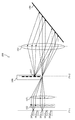
ここで、図14に従来の波長選択スイッチの概略構成図を示す。 Here, FIG. 14 shows a schematic configuration diagram of a conventional wavelength selective switch.
図14の波長選択スイッチ200は、焦点位置に配置された光入出力ポート101cから出力される光を平行光にするマイクロレンズアレイ102と、マイクロレンズアレイ102からの光を収束させる高開口数レンズ103と、高開口数レンズ103と焦点位置を共通に配置された第二レンズ104と、第二レンズ104からの光を波長ごとに異なる角度に反射する回折格子105と、第二レンズ104の焦点位置に配置され回折格子105から第二レンズ104を透過した光を第二レンズ104に向けて任意の角度で反射するアレイミラー106と、を備える(例えば、特許文献1を参照。)。
A wavelength
これにより、アレイミラー106において任意の角度で反射された光は、アレイミラー106の個々のミラーの角度に応じて波長ごとに異なる光入出力ポートに収束させることができる。このように、高開口数レンズ103は、アレイミラー106で反射した光のうち回折格子105で再び反射して第二レンズ104を透過した光の角度を変えるとともに光入出力ポート101cからの光の光軸にオフセットを付与する機能(以下、当該機能を「角度/オフセット変換」機能という。)を有している。
As a result, the light reflected by the
しかし、従来の波長選択スイッチ200は、高開口数レンズ103及びマイクロレンズアレイ102が必要であり、部品点数が多くなってしまうという問題がある。
However, the conventional wavelength
そこで、本発明では、部品点数が少なく簡易な構成の波長選択スイッチを提供することを目的とする。 Therefore, an object of the present invention is to provide a wavelength selective switch having a simple configuration with a small number of parts.
上記目的を達成するために、本発明では、ミラーで反射した光の光軸にオフセットを付与するシリンドリカル凹レンズを適用することとした。 In order to achieve the above object, in the present invention, a cylindrical concave lens that applies an offset to the optical axis of the light reflected by the mirror is applied.
具体的には、本願第一発明に係る波長選択スイッチは、一以上の波長を含む光を入出力し、横並び直線状に設けられた複数の光入出力ポートに対向して前記光入出力ポートからの光を平行光にするように配置された第一レンズと、前記第一レンズを間にして前記複数の光入出力ポートの反対側に配置され、前記光入出力ポートから入出力される光のうち前記第一レンズを透過した光を受ける面上に前記複数の光入出力ポートの配置方向に平行な複数の格子が形成された格子面において前記第一レンズを透過した光を波長ごとに異なる角度で反射する回折格子と、前記光入出力ポートから出力され前記回折格子で反射した光のうち前記第一レンズを透過した光を透過させて前記複数の光入出力ポートの配列方向では凹レンズとしての作用を持ち前記第一レンズからの収束光を平行光束に変換し、前記複数の光入出力ポートの配列方向と直交する方向ではレンズ作用を持たず前記第一レンズからの収束光をそのまま収束させるように前記第一レンズを間にして前記回折格子の反対側に配列されたシリンドリカル凹レンズと、前記光入出力ポートから出力され前記回折格子で反射し前記第一レンズ及び前記シリンドリカル凹レンズを透過した光を、前記シリンドリカル凹レンズを間にして前記第一レンズの反対側で前記シリンドリカル凹レンズの焦点距離だけ離れた位置においてそれぞれ反射し、反射した光のそれぞれが前記シリンドリカル凹レンズ及び前記第一レンズを透過して前記回折格子で反射し再び前記第一レンズを透過して前記複数の光入出力ポートのいずれかに収束するように光の反射角度がそれぞれ設定された複数のミラーと、を備える。 Specifically, the wavelength selective switch according to the first invention of the present application inputs / outputs light including one or more wavelengths, and faces the plurality of optical input / output ports arranged in a side-by-side straight line, to the optical input / output port. The first lens arranged so as to make the light from the parallel light and the first lens in between are arranged on the opposite side of the plurality of light input / output ports and input / output from the light input / output ports The light transmitted through the first lens in a grating plane in which a plurality of gratings parallel to the arrangement direction of the plurality of light input / output ports is formed on the surface of the light that receives the light transmitted through the first lens for each wavelength. A diffraction grating that reflects at different angles, and light that is output from the light input / output port and reflected by the diffraction grating is transmitted through the first lens, and in the arrangement direction of the plurality of light input / output ports. Acts as a concave lens The convergent light from the first lens is converted into a parallel light beam, and the convergent light from the first lens is converged as it is without having a lens action in a direction orthogonal to the arrangement direction of the plurality of light input / output ports. A cylindrical concave lens arranged on the opposite side of the diffraction grating with a first lens interposed therebetween, and light output from the light input / output port and reflected by the diffraction grating and transmitted through the first lens and the cylindrical concave lens, Each of the reflected light beams is reflected at a position away from the first lens by a focal distance of the cylindrical concave lens with a cylindrical concave lens in between, and each of the reflected light passes through the cylindrical concave lens and the first lens and passes through the diffraction grating. So that the light beam is reflected through the first lens and again passes through the first lens to converge to one of the plurality of light input / output ports. And a plurality of mirrors reflection angle of light is set respectively, the.
本発明は、回折格子で反射する反射型の波長選択スイッチに該当する。本発明の波長選択スイッチは、シリンドリカル凹レンズを備えるため、複数のミラーで反射した光の光軸を複数の光入出力ポートの配列方向にオフセットを付与することができる。これにより、角度/オフセット変換機能をシリンドリカル凹レンズの1つで実現でき、部品点数を削減して簡易な構成にすることができる。また、小型化も可能である。さらに、第一レンズから光入出力ポートへの光の入力角度を光入出力ポートに対して略垂直となるように調整すれば低損失の波長選択スイッチが実現できる。 The present invention corresponds to a reflective wavelength selective switch that reflects light from a diffraction grating. Since the wavelength selective switch of the present invention includes the cylindrical concave lens, the optical axis of the light reflected by the plurality of mirrors can be offset in the arrangement direction of the plurality of light input / output ports. Thereby, the angle / offset conversion function can be realized by one of the cylindrical concave lenses, and the number of parts can be reduced and a simple configuration can be achieved. In addition, miniaturization is possible. Furthermore, a low-loss wavelength selective switch can be realized by adjusting the light input angle from the first lens to the light input / output port so as to be substantially perpendicular to the light input / output port.
また、本願第二発明に係る波長選択スイッチは、一以上の波長を含む光を入出力し、横並び直線状に設けられた複数の光入出力ポートに対向して前記光入出力ポートからの光を平行光にするように配置された第一レンズと、前記第一レンズを間にして前記複数の光入出力ポートの反対側に配置され、前記光入出力ポートから入出力される光のうち前記第一レンズを透過した光を受ける面上に前記複数の光入出力ポートの配置方向に平行な複数の格子が形成された格子面において前記第一レンズを透過した光を波長ごとに異なる角度で透過させる回折格子と、前記回折格子を間にして前記第一レンズの反対側に前記第一レンズと前記回折格子との距離と等しい距離だけ離れて配置される第二レンズと、前記光入出力ポートから出力され前記回折格子を透過した光のうち前記第二レンズを透過した光を透過させて前記複数の光入出力ポートの配列方向では凹レンズとしての作用を持ち前記第二レンズからの収束光を平行光束に変換し、前記複数の光入出力ポートの配列方向と直交する方向ではレンズ作用を持たず前記第二レンズからの収束光をそのまま収束させるように前記第二レンズを間にして前記回折格子の反対側に配列されたシリンドリカル凹レンズと、前記光入出力ポートから出力され前記第一レンズ、前記回折格子、前記第二レンズ及び前記シリンドリカル凹レンズを透過した光を、前記シリンドリカル凹レンズを間にして前記第二レンズの反対側で前記シリンドリカル凹レンズの焦点距離だけ離れた位置においてそれぞれ反射し、反射した光のそれぞれが前記シリンドリカル凹レンズ、前記第二レンズ及び前記第一レンズを透過して前記複数の光入出力ポートのいずれかに収束するように光の反射角度がそれぞれ設定された複数のミラーと、を備える。 Further, the wavelength selective switch according to the second invention of the present application inputs and outputs light including one or more wavelengths, and opposes a plurality of light input / output ports arranged side by side and in a straight line, from the light input / output ports. Of the light input / output from the light input / output port, the first lens disposed so as to be parallel light, and the first lens disposed on the opposite side of the plurality of light input / output ports The angle at which the light transmitted through the first lens is different for each wavelength on a grating surface in which a plurality of gratings parallel to the arrangement direction of the plurality of light input / output ports is formed on the surface that receives the light transmitted through the first lens. And a second lens disposed on the opposite side of the first lens by a distance equal to the distance between the first lens and the diffraction grating, and the light incident The diffraction output from the output port Of the light transmitted through the optical element, the light transmitted through the second lens is transmitted and acts as a concave lens in the arrangement direction of the plurality of light input / output ports to convert the convergent light from the second lens into a parallel light beam. In the direction perpendicular to the arrangement direction of the plurality of light input / output ports, the lens does not have a function, and the convergent light from the second lens is converged as it is, and the second lens is interposed between them so as to be opposite to the diffraction grating. The cylindrical concave lens arranged, and the light output from the light input / output port and transmitted through the first lens, the diffraction grating, the second lens, and the cylindrical concave lens Reflected at positions opposite to the focal length of the cylindrical concave lens on the opposite side, and each reflected light is reflected on the cylindrical lens. Concave lens, and a plurality of mirrors reflection angle of light is set, respectively, as by passing through the second lens and the first lens converges to one of the plurality of optical input and output ports.
本発明は、回折格子で反射する透過型の波長選択スイッチに該当する。本発明の波長選択スイッチは、シリンドリカル凹レンズを備えるため、複数のミラーで反射した光の光軸を複数の光入出力ポートの配列方向にオフセットを付与することができる。これにより、角度/オフセット変換機能をシリンドリカル凹レンズの1つで実現でき、透過型の波長選択スイッチの構成において、部品点数を削減して簡易な構成にすることができる。また、小型化も可能である。さらに、第一レンズから光入出力ポートへの光の入力角度を光入出力ポートに対して略垂直となるように調整すれば低損失の波長選択スイッチが実現できる。 The present invention corresponds to a transmission-type wavelength selective switch that is reflected by a diffraction grating. Since the wavelength selective switch of the present invention includes the cylindrical concave lens, the optical axis of the light reflected by the plurality of mirrors can be offset in the arrangement direction of the plurality of light input / output ports. Accordingly, the angle / offset conversion function can be realized by one cylindrical concave lens, and the number of components can be reduced and the configuration can be simplified in the configuration of the transmission type wavelength selective switch. In addition, miniaturization is possible. Furthermore, a low-loss wavelength selective switch can be realized by adjusting the light input angle from the first lens to the light input / output port so as to be substantially perpendicular to the light input / output port.
上記波長選択スイッチにおいて、前記複数の光入出力ポートと前記第一レンズとの間に配置され、前記複数のミラーで反射し前記第一レンズを透過した光が前記複数の光入出力ポートに対してそれぞれ略垂直に入力されるように光の前記複数の光入出力ポートへの入力角度を変える光入力角度変換レンズをさらに備えることが望ましい。 In the wavelength selective switch, the light that is disposed between the plurality of light input / output ports and the first lens, is reflected by the plurality of mirrors, and passes through the first lens, with respect to the plurality of light input / output ports. It is desirable to further include a light input angle conversion lens that changes the input angle of light to the plurality of light input / output ports so that the light is input substantially vertically.
本発明の波長選択スイッチでは、光入力角度変換レンズを備えるため、第一レンズから光入出力ポートへの光の入力角度を光入出力ポートに対して略垂直となるように調整できる。これにより、低損失の波長選択スイッチが実現できる。 Since the wavelength selective switch of the present invention includes the light input angle conversion lens, the light input angle from the first lens to the light input / output port can be adjusted to be substantially perpendicular to the light input / output port. Thereby, a low-loss wavelength selective switch can be realized.
上記波長選択スイッチにおいて、前記複数の光入出力ポートと前記第一レンズとの間で前記複数の光入出力ポートごとに配置され、前記複数のミラーで反射し前記第一レンズを透過した光が前記複数の光入出力ポートに対してそれぞれ略垂直に入力されるように光の前記複数の光入出力ポートへの入力角度を変える複数の光入力角度変換プリズムをさらに備えることが望ましい。 In the wavelength selective switch, the light that is arranged for each of the plurality of light input / output ports between the plurality of light input / output ports and the first lens, is reflected by the plurality of mirrors and is transmitted through the first lens. It is desirable to further include a plurality of light input angle conversion prisms that change the input angles of light to the plurality of light input / output ports so that the light is input substantially vertically to the plurality of light input / output ports.
本発明の波長選択スイッチでは、光入力角度変換プリズムを備えるため、第一レンズから光入出力ポートへの光の入力角度を光入出力ポートに対して略垂直となるように調整できる。これにより、低損失の波長選択スイッチが実現できる。また、光入力角度変換プリズムを光入出力ポートの前面に取り付けることが可能となるため、装置の大きさ増大への影響が小さく、装置の大きさをそのままに低損失の波長選択スイッチが実現できる。 Since the wavelength selective switch of the present invention includes the light input angle conversion prism, the light input angle from the first lens to the light input / output port can be adjusted to be substantially perpendicular to the light input / output port. Thereby, a low-loss wavelength selective switch can be realized. In addition, since the light input angle conversion prism can be attached to the front surface of the light input / output port, the influence on the increase in the size of the device is small, and a low-loss wavelength selective switch can be realized without changing the size of the device. .
上記波長選択スイッチにおいて、前記複数の光入出力ポートから入出力する光を伝搬させる光導波路が前記複数の光入出力ポートの配列間隔に応じて前記複数の光入出力ポートごとに設けられたピッチ変換、スポットサイズ変換、入出射角度変換の働きを持つ光導波路部品をさらに備えることが望ましい。なお、光導波路部品には、後述する光ファイバや光導波路回路を含む。 In the wavelength selective switch, a pitch in which an optical waveguide for propagating light input / output from the plurality of light input / output ports is provided for each of the plurality of light input / output ports according to an arrangement interval of the plurality of light input / output ports. It is desirable to further include an optical waveguide component having functions of conversion, spot size conversion, and incident / exit angle conversion. The optical waveguide component includes an optical fiber and an optical waveguide circuit described later.
これにより、光導波路のピッチ変換により光入出力ポートの配列間隔を等価的に縮小しミラー幅の縮小による波長選択スイッチ自体の小型化が可能となる。また光導波路のスポット半径変換により光入出力ポートのスポット半径を等価的に拡大しレンズ収差の低減による光結合の高効率化が可能となる。 Thereby, the arrangement interval of the optical input / output ports is equivalently reduced by the pitch conversion of the optical waveguide, and the wavelength selective switch itself can be downsized by reducing the mirror width. Further, the spot radius of the optical input / output port is equivalently enlarged by converting the spot radius of the optical waveguide, and the optical coupling can be made highly efficient by reducing the lens aberration.
なお、本発明に係る波長選択スイッチでは、上記の通り1つの光入出力ポートから出力された複数波長の光を他の複数の光入出力ポートに分波する機能として説明されるが、複数のミラーの角度を調整すれば複数の光入出力ポートから出力された光を1つの光入出力ポートに結合することもでき、当然に合波機能も有している。 The wavelength selective switch according to the present invention is described as a function of demultiplexing light of a plurality of wavelengths output from one light input / output port to a plurality of other light input / output ports as described above. If the angle of the mirror is adjusted, light output from a plurality of light input / output ports can be coupled to one light input / output port, and of course, it also has a multiplexing function.
本発明では、部品点数が少なく簡易な構成の波長選択スイッチを提供することが可能である。 In the present invention, it is possible to provide a wavelength selective switch having a simple configuration with a small number of parts.
以下、具体的に実施形態を示して本願発明を詳細に説明するが、本願の発明は以下の記載に限定して解釈されない。なお、以下の実施形態では、1つの光入出力ポート(後述の光入出力ポート20d)から光が出力され他の光入出力ポート(後述の光入出力ポート20a〜20g)のいずれかに光を波長ごとに分けて出力する構成について説明するが、当該他の光入出力ポート20a〜20gのいずれかから出力される光を波長ごとに分けて当該1つの光入出力ポート20dに入力する形態についても同様に説明できる。
Hereinafter, the present invention will be described in detail with specific embodiments, but the present invention is not construed as being limited to the following description. In the following embodiments, light is output from one light input / output port (light input /
(第一実施形態)
図1に、本実施形態に係る波長選択スイッチの概略構成図を示す。図1(a)は、x−z面での波長選択スイッチを示し、図1(b)は、y−z面での波長選択スイッチを示している。図1の波長選択スイッチ10は、反射型の構成、つまり、後述の回折格子31で光を反射する構成である。
(First embodiment)
FIG. 1 shows a schematic configuration diagram of a wavelength selective switch according to the present embodiment. 1A shows a wavelength selective switch in the xz plane, and FIG. 1B shows a wavelength selective switch in the yz plane. The wavelength
図1の波長選択スイッチ10は、光入出力ポート20dからの光を平行光にするように配置された凸レンズ30と、光入出力ポート20dからの光のうち凸レンズ30を透過した光を波長ごとに異なる角度で反射する回折格子31と、凸レンズ30を間にして回折格子31の反対側に配置されたシリンドリカル凹レンズ33と、回折格子31で反射し凸レンズ30及びシリンドリカル凹レンズ33を透過した光を、シリンドリカル凹レンズ33を間にして凸レンズ30の反対側でそれぞれ反射するミラー35a,35bと、を備える。但し、図1では、光入出力ポート20dから出力して回折格子31で反射し、ミラー35bに至るまでの光路については凸レンズ30、シリンドリカル凹レンズ33の作用を表すために破線で光束の広がりを示し、実線で主光線を示している。他の光路については図の錯綜を避けるため主光線のみを実線、又は一点鎖線で示している。
The wavelength
また、第一レンズとして、本実施形態では凸レンズ30を用いているが、ここで用いるレンズは凸レンズに限定されない。例えば、光学収差を低減させるために適切な凸レンズと凹レンズを接着して組み合わせたダブレットレンズやトリプレットレンズのように複数のレンズを組み合わせたレンズを用いてもよい。
Moreover, although the
光入出力ポート20a〜20gは、複数のポートを備えている。図1では、光入出力ポート20a〜20gと7つ記載しているが、これ以上又はこれ以下の任意の数で配置可能である。光入出力ポート20a〜20gには、例えば、図1に示すように光入出力ポート20a〜20gごとに光ファイバ40a〜40gが接続され、又は、光導波路(後述の図7のピッチ変換光導波路42a〜42gを参照。)が接続される。また、光入出力ポート20a〜20gは、それぞれ光ファイバ40a〜40gを伝搬する一以上の波長を含む光を入出力する。また、光入出力ポート20a〜20gは、横並び直線状に設けられ、光入出力ポート20a〜20gに対向して配置された凸レンズ30が光入出力ポート20a〜20gからの光を平行光に変換しうるように、凸レンズ30から凸レンズ30の焦点距離fmだけ離れた位置に配置される。図1では、図1(b)に示すように、光入出力ポート20a〜20gは、光入出力ポート20a〜20gから出力される光の向きがz軸方向に平行となるように配置されているが、凸レンズ30において平行光に変換されるのであれば、いずれの向きに向いていてもよい。例えば、図1に示すように光入出力ポート20a〜20gが焦点距離fmだけ離れた位置に配置される場合、光入出力ポート20a〜20gの向きは凸レンズ30に対して斜めであってもよい。
The optical input /
回折格子31は、凸レンズ30を間にして光入出力ポート20a〜20gの反対側に配置される。また、図1では、共焦点系を構成するため、回折格子31は、凸レンズ30から凸レンズ30の焦点距離fmだけ離れた位置に配置される。図1のように共焦点系を構成すると波長選択スイッチ10を小型にすることができ有効である。
The
また、回折格子31の格子面32上には、光入出力ポート20a〜20gの配置方向に平行となるように配置された格子(不図示、以下本明細書において同じである。)が形成されている。図1では、格子面32上には、図1(b)のy軸方向に平行な格子が図1(a)のx軸方向に並列に複数形成される。格子は、格子面32上に形成された複数の凹凸形状の溝であってもよいし、光を反射する部分と吸収する部分とを交互に配置してもよい。これにより、図1(a)に示すように、凸レンズ30を透過した光は、回折格子31の格子面32上で反射してx軸方向に波長ごとに異なる角度で反射する。なお、図1(b)のz軸方向にはそのまま返送される。図1では簡単のため回折格子31の格子面32は、凸レンズ30に正対しているが、一般的には格子面32の法線がxz面内にあるように光軸(z軸)に対して傾斜している。
On the
シリンドリカル凹レンズ33は、回折格子31で反射した光のうち凸レンズ30を透過した光を透過させて後述のミラー35a,35bに向けて収束させる。シリンドリカル凹レンズ33は、図1(a)のx−z面、つまり光入出力ポート20a〜20gの配列方向と直交する方向(x方向)では単純平板であり、凸レンズ30からの焦点距離fmよりも若干長くなる位置に、凸レンズ30からの光をそのまま収束させる。一方、図1(b)のy−z面、つまり光入出力ポート20a〜20gの配列方向(y方向)では凹レンズとして機能し、凸レンズ30からの光を平行光に変換してミラー35a,35bに導く。図1では、シリンドリカル凹レンズ33は、凹面34がミラー35a,35bの側を向くように配置されるが、凸レンズ30の側を向くように配置しても当然によい。また、図1では、平凹のシリンドリカルレンズを適用しているが、両凹のシリンドリカルレンズでもよい。
The cylindrical
ミラー35a,35bは、図1では2つ記載しているが、光ファイバ40内を伝搬する光の波長数に応じて波長ごとに複数配置するとよい。以下、ミラー35aを中心に説明するが、ミラー35bも同様である。ミラー35aは、シリンドリカル凹レンズ33の焦点距離f3だけ離れた位置に配置される。そして、シリンドリカル凹レンズ33からの光が収束する位置でシリンドリカル凹レンズ33からの収束光を任意の角度で反射する。また、ミラー35aで反射した光がシリンドリカル凹レンズ33及び凸レンズ30を透過して回折格子31で反射し再び凸レンズ30を透過して光入出力ポート20a〜20gのいずれかに収束するように光の反射角度がそれぞれ設定される。図1では、ミラー35aでは、光入出力ポート20cに、ミラー35bでは、光入出力ポート20eに、それぞれ収束するように設定されているが、角度に応じて光入出力ポート20a〜20gのいずれにも収束させることは可能である。例えば、ミラー35aのように角度を上方に傾けると凸レンズ30及び回折格子31を通して光入出力ポート20cに収束させることができ、一方、ミラー35bのように下方に傾けると凸レンズ30及び回折格子31を通して光入出力ポート20eに収束させることができる。このように、ミラー35aの角度を変えることで波長選択が可能となる。ミラー35aとしては、例えば、MEMS(Micro Electro Mechanical Systems)ミラーを適用して小型の波長選択スイッチを実現することができる。
Although two
以上より、波長選択スイッチ10は、光入出力ポート20a〜20gのいずれかから出力される複数波長の光を他の光入出力ポート(光入出力ポート20a〜20gのいずれか)に振分けたり、光入出力ポート20a〜20gのうち複数から出力される光を他の1つの光入出力ポート(光入出力ポート20a〜20gのいずれか)で合波することができるため、光波長多重通信ネットワーク実現の際の波長多重用の光合分波回路や波長再配置型のadd−drop波長多重回路として適用できる。
From the above, the wavelength
ここで、ミラー35aで反射した光の軌跡について詳細に説明する。
Here, the locus of light reflected by the
図3は、ミラー35aとシリンドリカル凹レンズ33を示した概略図である。
FIG. 3 is a schematic view showing the
図3に示すように、ミラー35aにおいて角度θmで反射した主光線55は、ミラー35aへの入射光56の光軸60からh=|f3|θmの高さでシリンドリカル凹レンズ33を透過する。これは、ミラー35aをシリンドリカル凹レンズ33からシリンドリカル凹レンズ33の焦点距離f3だけ離れた位置に配置したためである。シリンドリカル凹レンズ33を透過した主光線55は、シリンドリカル凹レンズ33透過時の屈折角度がh/|f3|=θmであり、出射角度は、θm+h/|f3|=2θmとなる。つまり、シリンドリカル凹レンズ33を透過した主光線55は、シリンドリカル凹レンズ33の焦点から高さ−hの点を光源として出射される光線と一致するとみることができ、ミラー35aに入射する入射光56の反射位置を等価的に−hだけy方向にオフセットすることができることがわかる。
As shown in FIG. 3, the
以上説明したように、図1の波長選択スイッチ10は、シリンドリカル凹レンズ33を備えるため、角度/オフセット変換機能をシリンドリカル凹レンズ33の1つで実現でき、部品点数を削減して簡易な構成にすることができる。また、小型化も可能となる。さらに、後述のように、凸レンズ30から光入出力ポート20a〜20gへの光の入力角度を光入出力ポート20a〜20gに対して略垂直となるように調整すれば低損失の波長選択スイッチが実現できる。
As described above, since the wavelength
(第二実施形態)
図4に、本実施形態に係る波長選択スイッチの概略構成図を示す。図4(a)は、x−z面での波長選択スイッチを示し、図4(b)は、y−z面での波長選択スイッチを示している。なお、図4において図1と同じ符号のものは相互に同じものであるため、その部分の説明は省略する。
(Second embodiment)
FIG. 4 is a schematic configuration diagram of the wavelength selective switch according to the present embodiment. FIG. 4A shows the wavelength selective switch in the xz plane, and FIG. 4B shows the wavelength selective switch in the yz plane. In FIG. 4, the same reference numerals as those in FIG. 1 are the same as each other, and the description thereof is omitted.
図4の波長選択スイッチ12は、光入出力ポート20a〜20gと凸レンズ30との間で凸レンズ30を透過した光の光入出力ポート20a〜20gへの入力角度を変える光入力角度変換レンズ38を備えている。
The wavelength
光入力角度変換レンズ38は、ミラー35aで反射し凸レンズ30を透過した光が光入出力ポート20a〜20gに対してそれぞれ略垂直に入力されるように配置される。図4では、光入力角度変換レンズ38として、シリンドリカル凹レンズ33の焦点距離f3の1/2倍の焦点距離f4を有する凸レンズを適用し、凸レンズ30の焦点の位置が光入力角度変換レンズ38の焦点距離f4の2倍の距離(つまり、シリンドリカル凹レンズ33の焦点距離f3)だけ離れた位置にくるように凸レンズ30に対向して配置される。また、光入力ポート20a〜20gは、光入力角度変換レンズ38から光入力角度変換レンズ38の焦点距離f4の2倍の距離(つまり、シリンドリカル凹レンズ33の焦点距離f3)だけ離れた位置に配置される。本実施形態では、光入力角度変換レンズ38として凸レンズを用いているが、ここで用いるレンズは凸レンズに限定されない。凸レンズの機能さえあれば、例えば、単レンズ、凸レンズと凹レンズとを接着して組合わせたダブレットレンズのように複数のレンズを組み合わせたレンズ、又は非球面レンズを用いてもよい。
The light input
ここで、光入力角度変換レンズ38を透過する光の軌跡について詳細に説明する。
Here, the locus of light transmitted through the light input
図5は、光ファイバ40と光入力角度変換レンズ38を示した概略図である。
FIG. 5 is a schematic view showing the
光入力角度変換レンズ38の焦点距離f4の2倍の距離だけ離れた位置に光入力角度変換レンズ38の中心軸61からの高さが−hの位置に光入出力ポート20eを配置して、光入力角度変換レンズ38の中心軸61からの高さが−hの位置に向けて角度2θmの光51を入射すると、光入力角度変換レンズ38の性質上、倍率1の倒立実像が、光ファイバ40の端面である光入出力ポート20eに結像する。そして、光入力角度変換レンズ38に入射した光51は、光ファイバ40のコア軸62に平行に入力される。
And height from the
以上説明したように、図4の波長選択スイッチ12では、光入力角度変換レンズ38を備えるため、凸レンズ30から光入出力ポート20a〜20gへの光の入力角度を光入出力ポート20に対して略垂直となるように調整できる。これにより、低損失の波長選択スイッチが実現できる。
As described above, since the wavelength
(第三実施形態)
本実施形態では、図4で説明した光入力角度変換レンズ38に代えて、光入力角度変換プリズムを備えている。
(Third embodiment)
In the present embodiment, a light input angle conversion prism is provided instead of the light input
図6に、本実施形態に光入力角度変換プリズムの概略構成図を示す。 FIG. 6 shows a schematic configuration diagram of a light input angle conversion prism in this embodiment.
図6の光入力角度変換プリズム39a〜39gは、複数備えている。図6では、光入力角度変換プリズム39a〜39gと7つ記載しているが、光入出力ポート20a〜20gの数に応じて光入出力ポートごとに配置する。また、光入力角度変換プリズム39a〜39gは、光入出力ポート20a〜20gと凸レンズ(不図示、図1等の凸レンズ30)との間に配置され、例えば、不図示の凸レンズを透過した光52が光入出力ポート20cに対して略垂直に入力されるように光52の光入出力ポート20cへの入力角度を変える。他の光入出力ポート20b,d〜gについても同様である。光入出力ポート20cに設けた光入力角度変換プリズム39cの頂角をθp、光入力角度変換プリズム39cの屈折率をnpとすると、角度2θmで入射する光52を光入力ポート20cである光ファイバ40cの端面に垂直にする条件は、次の数式(1)で表せる。
A plurality of light input

例えば、ここでnp=1.45、θm=1.5度とすると、θp=6.66度となる。光入出力ポート20cの位置を固定することで光入力角度変換プリズム39cの頂角θpの大きさを決定することができる。このことは、他の光入出力ポート20b,d〜gについても同様である。
For example, if n p = 1.45 and θ m = 1.5 degrees, then θ p = 6.66 degrees. It is possible to determine the size of the apex angle theta p of the light input
以上説明したように、本実施形態に係る波長選択スイッチでは、光入力角度変換プリズム39a〜39gを備えるため、不図示の凸レンズから光入出力ポート20a〜20gへの光の入力角度を光入出力ポート20a〜20gに対して略垂直となるように調整できる。これにより、低損失の波長選択スイッチが実現できる。また、光入力角度変換プリズム39a〜39gを光入出力ポート20a〜20gの前面に取り付けることが可能となるため、装置の大きさ増大への影響が小さく、装置の大きさをそのままに(例えば、図1の波長選択スイッチ10の大きさそのまま)低損失の波長選択スイッチが実現できる。
As described above, since the wavelength selective switch according to the present embodiment includes the light input
(第四実施形態)
図7に、本実施形態に係る波長選択スイッチとその周辺部の概略構成図を示す。図7(a)は、x−z面での波長選択スイッチを示し、図7(b)は、y−z面での波長選択スイッチを示している。なお、図7において図1と同じ符号のものは相互に同じものであるため、その部分の説明は省略する。
(Fourth embodiment)
FIG. 7 shows a schematic configuration diagram of the wavelength selective switch and its peripheral part according to the present embodiment. FIG. 7A shows the wavelength selective switch in the xz plane, and FIG. 7B shows the wavelength selective switch in the yz plane. In FIG. 7, the same reference numerals as those in FIG. 1 are the same as those in FIG.
図7の波長選択スイッチ13には、光入出力ポート20a〜20gで入出力される光を伝搬する光ファイバ40a〜40gと光入出力ポート20a〜20gとの間で光入出力ポート20a〜20gの配置間隔と光ファイバ40a〜40gの配置間隔とを相互に変換するピッチ変換光導波路42a〜42gが接続されている。ピッチ変換光導波路42a〜42gは、光導波路回路41として構成される。光ファイバ40の外径に制約があり、例えば、直径125μm以下にできないような場合、有効である。光入出力ポート20a〜20gの配置間隔は、後述するようにミラー35aの大きさに影響を与えるからである。
In the wavelength
光ファイバ40は、複数備える。図7では、光ファイバ40a〜40gの7つ記載しているが、光入出力ポート20a〜20gのポート数に応じて光入出力ポートごとに複数配置する。
A plurality of
ここで、図7のミラー35aの反射面63a上の光のスポット半径ωmyは、次の数式(2)と表せる。数式(2)において、λは光入出力ポート20a〜20gで入出力される光の波長、ωfは光入出力ポート20dから出力される光のスポット半径である。一方、光入出力ポート20a〜20gの配置間隔DFとシリンドリカル凹レンズ33の焦点距離f3との関係は、次の数式(3)と表せる。数式(3)において、θmはミラー35aの反射角度である。さらに、数式(2)、数式(3)から、数式(4)を導ける。
Here, the spot radius ω my of the light on the reflecting
ここで、ミラー35aの反射面63a上の光のスポット直径2ωmyは、y−z面におけるミラー35aの幅Myより小さいことが要求される。この要求条件を満たすためには、波長λ、及び光入出力ポート20dから出力される光のスポット半径ωfが与えられるとして、シリンドリカル凹レンズ33の焦点距離f3を適切な値にする必要がある。
Here, spot diameter 2 [omega my of light on the reflecting
スポット直径2ωmyは、λ,ωf,θmを一定とすると、数式(4)から光入出力ポート20a〜20gの配置間隔DFに比例することが分かる。そのため、スポット直径2ωmyを小さくするためには、数式(4)より、光入出力ポート20a〜20gの配置間隔DFを小さくすればよいが、上記の通り、光入出力ポート20a〜20gに直接光ファイバを接続する場合には、光入出力ポート20a〜20gの配置間隔DFには下限がある。そこで、図7に示すようにピッチ変換光導波路42a〜42gを備えると、光入出力ポート20a〜20gの配置間隔DFを光ファイバを直接接続した場合と比べて小さくすることができる。
It can be seen that the spot diameter 2ω my is proportional to the arrangement interval DF of the optical input /
例えば、ピッチ変換光導波路42aの端面である光入出力ポート20dから出力される光のスポット半径ωf=5.2μm、光入出力ポート20a〜20gの配置間隔DF=25μmとする。また、ミラー35aの最大変位角度を±1.5度、光入出力ポートの数を10個(但し、図7では、光入出力ポート20a〜20gとして7つ記載している。)とすると、隣接する光入出力ポート(例えば、光入出力ポート20eと光入出力ポート20f)への光の入力角度の切換角度θmは、ミラー35aが反射ミラーであることを考慮し、最大変位角度±1.5度を10分割した0.3度の2倍でθm=0.6度(0.0105rad)となる。数式(3)から、シリンドリカル凹レンズ33の焦点距離f3=2.5μm/0.0105rad=2.39mmとなる。数式(4)から、光の波長λ=1.5447μmとして、ミラー35aの反射面63a上の光のスポット直径2ωmy=452μmとなり、必要なミラー35aの幅Myは、My=500μm程度であることがわかる。
For example, the spot radius ω f of the light output from the optical input /
一方、λ,ωf,θmの条件を上記と同じとして、外径125μmの光ファイバをピッチ127μmのV格子基板にアレイ状に配置して直接光入出力ポートに接続した場合には、数式(4)より、ミラーの幅Myとして2.5mm程度が必要であることがわかる。ミラー35aの幅Myを小さくするためには、λ,ωfは略固定であるため、数式(4)より、θmを大きくする必要がある。θmを±1.5度の5倍の±7.5度とすれば、ミラーの幅Myを500μm程度とすることができるが、ミラー35aの最大変位角度を超えてしまう。
On the other hand, when the conditions of λ, ω f , and θ m are the same as described above, and optical fibers having an outer diameter of 125 μm are arranged in an array on a V-grid substrate having a pitch of 127 μm and directly connected to the optical input / output port, (4) from, 2.5mm approximately be seen that it is necessary as a width M y of the mirror. To reduce the width M y of the
以上説明したように、ピッチ変換光導波路42a〜42gを備えると、波長選択スイッチ13は、ミラー35aの幅Myを小さくすることができ波長選択スイッチ13全体を小型のままに光ファイバ40に接続することができる。
As described above, when provided with a
(第五実施形態)
本実施形態では、図7の波長選択スイッチ13が、先端部分がテーパ状のピッチ変換光導波路に接続されている。ピッチ変換光導波路は、図7で説明したピッチ変換光導波路42a〜42gと同様である。
(Fifth embodiment)
In the present embodiment, the wavelength
図8に、本実施形態にピッチ変換光導波路の先端部分の概略図を示す。 FIG. 8 shows a schematic diagram of the tip portion of the pitch conversion optical waveguide in this embodiment.
図8のピッチ変換光導波路42a〜42gは、その先端部分がテーパ状である。ピッチ変換光導波路42a〜42gのコア幅を次第に狭くするテーパ状にすると、導波路内の光のクラッドによる拘束が緩み、スポットサイズが拡大する。これにより、数式(4)から分かるように、半径ωfを拡大して、図7のミラー35aの反射面63a上のスポット直径2ωmyを小さくすることができる。
The pitch conversion
図8に示すようにスポット半径ωfとなる導波路幅Wfの定常導波路部45に先端がテーパ状のピッチ変換光導波路42a〜42gを接続すると、ピッチ変換光導波路42a〜42g内を伝搬する光は、テーパ導波路部46の等価屈折率低減でスポット半径が徐々に拡大しスポット拡大部47に導かれる。図7のミラー35aの反射面63a上のy−z面内のスポット半径ωmyの拡大と同時にx−z面内のスポット半径ωmzもスポット半径ωfより拡大するが、これらのスポット半径ωmz,ωmyの拡大で図7の凸レンズ30の収差が低減する傾向となり、より効率のよい光結合が得られる。
When the leading end to the
また、前述のように、例えば、図7で説明したようにピッチ変換光導波路42aからの光のスポット半径ωf=5.2μm、光入出力ポート20a〜20gの配置間隔DF=25μm、また、ミラー35aの最大変位角度を±1.5度、光入出力ポート20a〜20gの数を10個(但し、図7では、光入出力ポート20として7つ記載している。)とすると、隣接する光入出力ポート(例えば、光入出力ポート20dと光入出力ポート20b)への光の入力角度の切換角度θm=0.6度(0.0105rad)、シリンドリカル凹レンズ33の焦点距離f3=2.5μm/0.0105rad=2.39mmとなる。スポット半径ωfの拡大で3倍に拡大されるとωf=15.6μmとなる。光の波長λ=1.5447μmとして、数式(4)から図7のミラー35aの反射面63a上の光のスポット直径2ωmy=150μmとなり、ミラー35aの幅Myは、スポットサイズに逆比例して小さくなることが分かる。これにより、ミラー35a自体をより現実的な大きさして、波長選択スイッチ13全体を小型にすることができる。
Further, as described above, for example, as described in FIG. 7, the spot radius ω f of the light from the pitch converting
(第六実施形態)
図9に、本実施形態に係る波長選択スイッチとその周辺部の概略構成図を示す。図9(a)は、x−z面での波長選択スイッチを示し、図9(b)は、y−z面での波長選択スイッチを示している。なお、図9において図1と同じ符号のものは相互に同じものであるため、その部分の説明は省略する。
(Sixth embodiment)
FIG. 9 shows a schematic configuration diagram of the wavelength selective switch and its peripheral portion according to the present embodiment. FIG. 9A shows a wavelength selective switch in the xz plane, and FIG. 9B shows a wavelength selective switch in the yz plane. In FIG. 9, the same reference numerals as those in FIG. 1 are the same as each other, and the description thereof is omitted.
図9の波長選択スイッチ14には、光入出力ポート20a〜20gで入出力される光を伝搬する光ファイバ40a〜40gと光入出力ポート20a〜20gとの間で光入出力ポート20a〜20gの配置間隔と光ファイバ40a〜40gの配置間隔とを相互に変換するピッチ変換光導波路44a〜44gが接続されている。図9の波長選択スイッチ14は、図1の波長選択スイッチ10と同一の波長選択スイッチである。図9は、ピッチ変換光導波路44a〜44gを備える点で第四及び第五実施形態で説明した波長選択スイッチ13(図7を参照。)において光入力角度変換レンズ38を取り去った構成を示している。
In the wavelength
図9のピッチ変換光導波路44a〜44gは、光導波路回路43として構成され、光入出力ポート20a〜20gへの光の入力角度2θmと同じ傾斜角度を持って配置されている。ピッチ変換光導波路44a〜44gのコア間のクロストークを避けるために、コアとコアとの間に遮光格子をつけてもよい。また、図8で説明したように先端部分をテーパ状にして、スポットサイズの拡大により出力を傾斜させてもよい。
本実施形態のように光導波路が傾斜したピッチ変換光導波路44a〜44gを備えると、波長選択スイッチ14は、より小型にできるとともに、効率のよい光結合で光ファイバ40に接続することができる。
When the pitch conversion
(第七実施形態)
図2に、本実施形態に係る波長選択スイッチの概略構成図を示す。図2(a)は、x−z面での波長選択スイッチを示し、図2(b)は、y−z面での波長選択スイッチを示している。なお、図2において図1と同じ符号のものは相互に同じものであるため、その部分の説明は省略する。図2の波長選択スイッチは、透過型の構成、つまり、後述の回折格子で光を透過させる構成である。
(Seventh embodiment)
FIG. 2 shows a schematic configuration diagram of the wavelength selective switch according to the present embodiment. FIG. 2A shows a wavelength selective switch in the xz plane, and FIG. 2B shows a wavelength selective switch in the yz plane. 2 that are the same as those in FIG. 1 are the same as those in FIG. The wavelength selective switch of FIG. 2 has a transmission type configuration, that is, a configuration in which light is transmitted through a diffraction grating described later.
図2の波長選択スイッチ11は、図1の波長選択スイッチ10と異なる構成部分に代えて、光入出力ポート20a〜20gから入出力される光のうち凸レンズ30を透過した光を波長ごとに異なる角度で透過させる回折格子36と、回折格子36を間にして凸レンズ30の反対側に凸レンズ30と回折格子36との距離と等しい距離だけ離れて配置される凸レンズ37と、を備える。但し、回折格子36は、凸レンズ30を透過した光を透過させる点が異なる他は、図1の回折格子31と同様である。この場合、格子面32上に形成される格子は、格子面32上に形成された複数の凹凸形状の溝であってもよいし、光を透過する部分と反射又は吸収する部分とを交互に配置したスリット状であってもよい。また、凸レンズ37は、凸レンズ30と同一のレンズを適用している。
The wavelength
以上の構成により、図2の波長選択スイッチ11は、図1で説明した波長選択スイッチ10と同様の機能を発揮して波長選択することができる。なお、第二から第六実施形態で説明した波長選択スイッチ及びその周辺部の構成も当然に図2の波長選択スイッチ11にも適用することができる。
With the above configuration, the wavelength
ここで、第一から第七実施形態に係る波長選択スイッチの透過特性について説明する。図1を中心に説明するが、図4、図7及び図9に示す波長選択スイッチ12,13,14でも同様である。
Here, the transmission characteristics of the wavelength selective switch according to the first to seventh embodiments will be described. 1 will be mainly described, but the same applies to the wavelength
図1のミラー35aのx−z面内の幅Mzがミラー35aの反射面63a上のスポット直径2ωmに比べて大きい場合には、透過特性が広く且つ急峻な遮断特性を有する合分波特性が得られることが既に知られている(例えば、非特許文献1を参照。)。
When the width M z of x-z plane of the
図10に、スポット半径ωのガウスビームスポットが波長変化とともにミラー35aの反射面63a上を移動する様子を示す。
FIG. 10 shows a state in which a Gaussian beam spot having a spot radius ω moves on the reflecting
δλ=100GHzの波長変化でビームスポットは、ミラー35a,35b間のピッチMp=δλ×LDだけ移動する。ピッチMpは、以下の数式(5)と表せる。数式(5)において、LDは、図1の回折格子31の格子定数と凸レンズ30の焦点距離fmで決定する定数(線分散)である。
The beam spot moves by a pitch M p = δλ × LD between the
また、λ0.5=60GHzの波長変化でビームスポットが結合損失の0.5dB増加する幅だけ移動すると以下の数式(6)の関係がある。 Further, when the beam spot is moved by a width that increases 0.5 dB of the coupling loss with a wavelength change of λ 0.5 = 60 GHz, the following equation (6) is established.
ビームスポットが波長とともに移動しミラー35a,35bからはみ出さない範囲が通過帯域であるから通過帯域は概ね(Mz−2ω)に比例する。実際にはミラー35a,35bの両端で0.5dB分のはみだしを許容するため、厳密には(Mz−1.59ω)に比例する。
Since the range in which the beam spot moves with the wavelength and does not protrude from the
具体例として、ミラー35aの幅Mzをミラー35a,35b間のピッチMpの85%(これを、ミラー35a,35bのフィルタファクターと呼ぶ。)として、δλ=100GHz,λ0.5=60GHzとすると、数式(5)、(6)から、ミラー35a,35b間のピッチMpとガウスビームのスポット半径ωとの関係が以下の数式(7)と表せる。
As a specific example, the width M z mirror 35a of the
Mp=130μmとすると、数式(7)から、要求されるωは、ω=20μmとなる。また、数式(5)のLDを数式(6)に代入すると、以下の数式(8)が導ける。 Assuming that M p = 130 μm, from Equation (7), the required ω is ω = 20 μm. Further, when the LD of the formula (5) is substituted into the formula (6), the following formula (8) can be derived.
数式(8)において、Mp=130μmと仮定すると、λ0.5とガウスビームのスポット半径ωとの関係が得られる。 In Equation (8), assuming that M p = 130 μm, the relationship between λ 0.5 and the Gaussian beam spot radius ω is obtained.
図11に、ガウスビームのスポット半径ωと100GHzの波長間隔における0.5dBの通過帯域λ0.5との関係を示したグラフを示す。スポット半径ωを2μmから30μmまで変化させたときの関係を示している。 FIG. 11 is a graph showing the relationship between the spot radius ω of the Gaussian beam and the 0.5 dB passband λ 0.5 at a wavelength interval of 100 GHz. The relationship when the spot radius ω is changed from 2 μm to 30 μm is shown.
図11から、図10のミラー35a,35b間のピッチMpとフィルタファクターを一定とすると、ωが大きくなるほどλ0.5が小さくなることが分かる。従来技術では、図14に示すように、P5−2面でのスポット半径ωP5−2がアレイミラー106の反射面107上でのスポット半径ωarrと等しくなることは図1と同様であるが、高開口数レンズ103の焦点距離f2、マイクロレンズアレイ102の焦点距離f1とすると、P5−1面もP5−2面も共焦点系であるため、光入出力ポート101dから出力される光のスポット半径ωfとすると、P5−2面でのスポット半径ωP5−2は、ωP5−2=(f2/f1)×ωfとなる。また、アレイミラー106の反射面107上でのスポット半径ωarrは、ωarr=ωP5−2となる。そのため、図14のマイクロレンズアレイ102の焦点距離f1は、高開口数レンズ103の焦点距離f2より短くなっており、ωを5.2μmとした場合、ωP5−2はその数倍の大きさになることがわかる。図11で分かるように、ωが大きくなると波長帯域は狭くなる傾向があるため、従来の波長選択スイッチでは通過帯域が狭くなる傾向がある。
From FIG. 11, it can be seen that if the pitch M p between the
一方、図1の波長選択スイッチ10では、ミラー35aの反射面63a上のx−z面でのスポット半径ωmzは、波長選択スイッチ10が共焦点系であるため、光入出力ポート20dから出力される光のスポット半径ωfと同じとなり、通常シングルモードファイバでは5.2μmとなる。よって、図7の波長選択スイッチ10は、λ0.5=85−159(ω/Mp)=79GHzと広い通過帯域を有することが分かる。
On the other hand, in the wavelength
図12に、本実施形態に係る波長選択スイッチの通過帯域特性の一例を示す。図13に、従来の波長選択スイッチの通過帯域特性の一例を示す。 FIG. 12 shows an example of passband characteristics of the wavelength selective switch according to this embodiment. FIG. 13 shows an example of passband characteristics of a conventional wavelength selective switch.
図13から従来の波長選択スイッチが0.5dB通過帯域幅が60GHzであり、通過帯域が狭く且つ遮断特性が緩慢である一方で、急峻な遮断特性を持つ一方で、図12から、図1の波長選択スイッチ10は、0.5dB通過帯域幅が70GHz以上で広帯域となっており、急峻な遮断特性を持つことが分かる。
From FIG. 13, the conventional wavelength selective switch has a 0.5 dB passband width of 60 GHz, a narrow passband and a slow cut-off characteristic, while having a steep cut-off characteristic, from FIG. It can be seen that the wavelength
本発明の波長選択スイッチは、異なる波長の光を分岐し又は結合することができ、光波長多重通信ネットワーク実現の際の波長多重用の光合分波回路や波長再配置型のadd−drop波長多重回路として適用できる。 The wavelength selective switch according to the present invention can branch or combine light of different wavelengths, and can be used for wavelength multiplexing optical multiplexing / demultiplexing circuits or wavelength rearrangement type add-drop wavelength multiplexing when realizing an optical wavelength multiplexing communication network. It can be applied as a circuit.
10,11,12,13,14:波長選択スイッチ
20a〜20g:光入出力ポート
30:凸レンズ
31:回折格子
32:格子面
33:シリンドリカル凹レンズ
34:凹面
35a,35b:ミラー
36:回折格子
37:凸レンズ
38:光入力角度変換レンズ
39a〜39g:光入力角度変換プリズム
40a〜40g:光ファイバ
41:光導波路回路
42a〜42g:ピッチ変換光導波路
43:光導波路回路
44a〜44g:ピッチ変換光導波路
45:定常導波路部
46:テーパ導波路部
47:スポット拡大部
51〜54:光
55:主光線
56:入射光
60:光軸
61:中心軸
62:コア軸
63a,63b:反射面
101,101a〜101d:光入出力ポート
102:マイクロレンズアレイ
103:高開口数レンズ
104:第二レンズ
105:回折格子
106:アレイミラー
107:反射面
200:波長選択スイッチ
10, 11, 12, 13, 14: Wavelength selection switches 20a to 20g: Optical input / output port 30: Convex lens 31: Diffraction grating 32: Grating surface 33: Cylindrical concave lens 34: Concave
Claims (5)
前記第一レンズを間にして前記複数の光入出力ポートの反対側に配置され、前記光入出力ポートから入出力される光のうち前記第一レンズを透過した光を受ける面上に前記複数の光入出力ポートの配置方向に平行な複数の格子が形成された格子面において前記第一レンズを透過した光を波長ごとに異なる角度で反射する回折格子と、
前記光入出力ポートから出力され前記回折格子で反射した光のうち前記第一レンズを透過した光を透過させて前記複数の光入出力ポートの配列方向では凹レンズとしての作用を持ち前記第一レンズからの収束光を平行光束に変換し、前記複数の光入出力ポートの配列方向と直交する方向ではレンズ作用を持たず前記第一レンズからの収束光をそのまま収束させるように前記第一レンズを間にして前記回折格子の反対側に配列されたシリンドリカル凹レンズと、
前記光入出力ポートから出力され前記回折格子で反射し前記第一レンズ及び前記シリンドリカル凹レンズを透過した光を、前記シリンドリカル凹レンズを間にして前記第一レンズの反対側で前記シリンドリカル凹レンズの焦点距離だけ離れた位置においてそれぞれ反射し、反射した光のそれぞれが前記シリンドリカル凹レンズ及び前記第一レンズを透過して前記回折格子で反射し再び前記第一レンズを透過して前記複数の光入出力ポートのいずれかに収束するように光の反射角度がそれぞれ設定された複数のミラーと、
を備える波長選択スイッチ。 A first lens arranged to input / output light including one or more wavelengths and to collimate light from the light input / output port so as to face a plurality of light input / output ports arranged side by side in a straight line When,
The plurality of light input / output ports disposed on the opposite side of the plurality of light input / output ports with the first lens interposed therebetween, wherein the plurality of light beams are input and output from the light input / output ports. A diffraction grating that reflects light transmitted through the first lens at a different angle for each wavelength in a grating plane on which a plurality of gratings parallel to the arrangement direction of the light input / output ports of
Of the light output from the light input / output port and reflected by the diffraction grating, the light transmitted through the first lens is transmitted and acts as a concave lens in the arrangement direction of the plurality of light input / output ports. The first lens so that the convergent light from the first lens is converged as it is without any lens action in a direction orthogonal to the arrangement direction of the plurality of light input / output ports. A cylindrical concave lens arranged on the opposite side of the diffraction grating in between,
The light output from the light input / output port and reflected by the diffraction grating and transmitted through the first lens and the cylindrical concave lens is only the focal length of the cylindrical concave lens on the opposite side of the first lens with the cylindrical concave lens in between. Each of the reflected light is reflected at a distant position, and each of the reflected light is transmitted through the cylindrical concave lens and the first lens, is reflected by the diffraction grating, is transmitted again through the first lens, and is transmitted through any of the plurality of light input / output ports. A plurality of mirrors each having a light reflection angle set so as to converge,
A wavelength selective switch comprising:
前記第一レンズを間にして前記複数の光入出力ポートの反対側に配置され、前記光入出力ポートから入出力される光のうち前記第一レンズを透過した光を受ける面上に前記複数の光入出力ポートの配置方向に平行な複数の格子が形成された格子面において前記第一レンズを透過した光を波長ごとに異なる角度で透過させる回折格子と、
前記回折格子を間にして前記第一レンズの反対側に前記第一レンズと前記回折格子との距離と等しい距離だけ離れて配置される第二レンズと、
前記光入出力ポートから出力され前記回折格子を透過した光のうち前記第二レンズを透過した光を透過させて前記複数の光入出力ポートの配列方向では凹レンズとしての作用を持ち前記第二レンズからの収束光を平行光束に変換し、前記複数の光入出力ポートの配列方向と直交する方向ではレンズ作用を持たず前記第二レンズからの収束光をそのまま収束させるように前記第二レンズを間にして前記回折格子の反対側に配列されたシリンドリカル凹レンズと、
前記光入出力ポートから出力され前記第一レンズ、前記回折格子、前記第二レンズ及び前記シリンドリカル凹レンズを透過した光を、前記シリンドリカル凹レンズを間にして前記第二レンズの反対側で前記シリンドリカル凹レンズの焦点距離だけ離れた位置においてそれぞれ反射し、反射した光のそれぞれが前記シリンドリカル凹レンズ、前記第二レンズ及び前記第一レンズを透過して前記複数の光入出力ポートのいずれかに収束するように光の反射角度がそれぞれ設定された複数のミラーと、
を備える波長選択スイッチ。 A first lens arranged to input / output light including one or more wavelengths and to collimate light from the light input / output port so as to face a plurality of light input / output ports arranged side by side in a straight line When,
The plurality of light input / output ports disposed on the opposite side of the plurality of light input / output ports with the first lens interposed therebetween, wherein the plurality of light beams are input and output from the light input / output ports. A diffraction grating that transmits light transmitted through the first lens at a different angle for each wavelength on a grating surface on which a plurality of gratings parallel to the arrangement direction of the light input / output ports of
A second lens disposed at a distance equal to the distance between the first lens and the diffraction grating on the opposite side of the first lens with the diffraction grating in between;
Of the light output from the light input / output port and transmitted through the diffraction grating, the light transmitted through the second lens is transmitted and acts as a concave lens in the arrangement direction of the plurality of light input / output ports. The second lens so as to converge the convergent light from the second lens without any lens action in a direction orthogonal to the arrangement direction of the plurality of light input / output ports. A cylindrical concave lens arranged on the opposite side of the diffraction grating in between,
The light output from the light input / output port and transmitted through the first lens, the diffraction grating, the second lens, and the cylindrical concave lens is inserted into the cylindrical concave lens on the opposite side of the second lens with the cylindrical concave lens in between. Light is reflected at each position separated by a focal length, and the reflected light passes through the cylindrical concave lens, the second lens, and the first lens and converges to one of the plurality of light input / output ports. A plurality of mirrors each having a reflection angle of
A wavelength selective switch comprising:
Priority Applications (2)
| Application Number | Priority Date | Filing Date | Title |
|---|---|---|---|
| JP2007059908A JP2008224824A (en) | 2007-03-09 | 2007-03-09 | Wavelength selection switches |
| PCT/JP2008/053912 WO2008111444A1 (en) | 2007-03-09 | 2008-03-05 | Wavelength selection switch |
Applications Claiming Priority (1)
| Application Number | Priority Date | Filing Date | Title |
|---|---|---|---|
| JP2007059908A JP2008224824A (en) | 2007-03-09 | 2007-03-09 | Wavelength selection switches |
Publications (1)
| Publication Number | Publication Date |
|---|---|
| JP2008224824A true JP2008224824A (en) | 2008-09-25 |
Family
ID=39759387
Family Applications (1)
| Application Number | Title | Priority Date | Filing Date |
|---|---|---|---|
| JP2007059908A Withdrawn JP2008224824A (en) | 2007-03-09 | 2007-03-09 | Wavelength selection switches |
Country Status (2)
| Country | Link |
|---|---|
| JP (1) | JP2008224824A (en) |
| WO (1) | WO2008111444A1 (en) |
Cited By (6)
| Publication number | Priority date | Publication date | Assignee | Title |
|---|---|---|---|---|
| WO2009025333A1 (en) * | 2007-08-23 | 2009-02-26 | Nippon Telegraph And Telephone Corporation | Optical signal processing device |
| WO2010110474A1 (en) * | 2009-03-27 | 2010-09-30 | 日本電信電話株式会社 | Optical switch |
| JP2012002883A (en) * | 2010-06-14 | 2012-01-05 | Nippon Telegr & Teleph Corp <Ntt> | Spatial light device |
| WO2015008489A1 (en) * | 2013-07-16 | 2015-01-22 | 日本電信電話株式会社 | Optical signal processing device |
| WO2015008349A1 (en) * | 2013-07-17 | 2015-01-22 | 住友電気工業株式会社 | Wavelength selector switch |
| US9326050B2 (en) | 2013-07-17 | 2016-04-26 | Sumitomo Electric Industries, Ltd. | Wavelength selective switch and method of manufacturing same |
Families Citing this family (2)
| Publication number | Priority date | Publication date | Assignee | Title |
|---|---|---|---|---|
| EP2299309B1 (en) * | 2008-07-04 | 2013-12-11 | NTT Electronics Corporation | Wavelength selection switch |
| JP2014074900A (en) * | 2012-09-13 | 2014-04-24 | Sumitomo Electric Ind Ltd | Wavelength selection switch |
Family Cites Families (5)
| Publication number | Priority date | Publication date | Assignee | Title |
|---|---|---|---|---|
| US6084695A (en) * | 1997-02-14 | 2000-07-04 | Photonetics | Optical fiber wavelength multiplexer and demutiplexer |
| JP2002214546A (en) * | 2000-11-15 | 2002-07-31 | Oki Electric Ind Co Ltd | Optical switch |
| JP2006030854A (en) * | 2004-07-21 | 2006-02-02 | Nikon Corp | Optical branch insertion device, device provided therewith, and method for controlling optical branch insertion device |
| JP2006178207A (en) * | 2004-12-22 | 2006-07-06 | Nikon Corp | Attenuator and optical switching apparatus |
| JP4254776B2 (en) * | 2005-10-31 | 2009-04-15 | 富士通株式会社 | Optical functional device |
-
2007
- 2007-03-09 JP JP2007059908A patent/JP2008224824A/en not_active Withdrawn
-
2008
- 2008-03-05 WO PCT/JP2008/053912 patent/WO2008111444A1/en active Application Filing
Cited By (15)
| Publication number | Priority date | Publication date | Assignee | Title |
|---|---|---|---|---|
| US8204347B2 (en) | 2007-08-23 | 2012-06-19 | Nippon Telegraph And Telephone Corporation | Optical signal processing device |
| JP2009053255A (en) * | 2007-08-23 | 2009-03-12 | Nippon Telegr & Teleph Corp <Ntt> | Optical signal processor |
| WO2009025333A1 (en) * | 2007-08-23 | 2009-02-26 | Nippon Telegraph And Telephone Corporation | Optical signal processing device |
| US8699832B2 (en) | 2009-03-27 | 2014-04-15 | Nippon Telegraph And Telephone Corporation | Optical switch |
| JP2010231020A (en) * | 2009-03-27 | 2010-10-14 | Nippon Telegr & Teleph Corp <Ntt> | Optical switch |
| WO2010110474A1 (en) * | 2009-03-27 | 2010-09-30 | 日本電信電話株式会社 | Optical switch |
| JP2012002883A (en) * | 2010-06-14 | 2012-01-05 | Nippon Telegr & Teleph Corp <Ntt> | Spatial light device |
| WO2015008489A1 (en) * | 2013-07-16 | 2015-01-22 | 日本電信電話株式会社 | Optical signal processing device |
| JPWO2015008489A1 (en) * | 2013-07-16 | 2017-03-02 | 日本電信電話株式会社 | Optical signal processing device |
| US9967050B2 (en) | 2013-07-16 | 2018-05-08 | Nippon Telegraph And Telephone Corporation | Optical signal processing device |
| WO2015008349A1 (en) * | 2013-07-17 | 2015-01-22 | 住友電気工業株式会社 | Wavelength selector switch |
| CN105408798A (en) * | 2013-07-17 | 2016-03-16 | 住友电气工业株式会社 | wavelength selective switch |
| US9326050B2 (en) | 2013-07-17 | 2016-04-26 | Sumitomo Electric Industries, Ltd. | Wavelength selective switch and method of manufacturing same |
| US9482822B2 (en) | 2013-07-17 | 2016-11-01 | Sumitomo Electric Industries, Ltd. | Wavelength selector switch |
| US9606296B2 (en) | 2013-07-17 | 2017-03-28 | Sumitomo Electric Industries, Ltd. | Optical path control device |
Also Published As
| Publication number | Publication date |
|---|---|
| WO2008111444A1 (en) | 2008-09-18 |
Similar Documents
| Publication | Publication Date | Title |
|---|---|---|
| US8391654B2 (en) | Wavelength selection switch | |
| JP4476140B2 (en) | Wavelength selective switch | |
| JP3852409B2 (en) | Optical functional device | |
| US8611742B2 (en) | Wavelength switch system using angle multiplexing optics | |
| CN103608708B (en) | Optical device | |
| JP2008224824A (en) | Wavelength selection switches | |
| KR20040036929A (en) | Free-space wavelength routing systems with interleaved channels | |
| CN101246239A (en) | Planar lightwave circuit based on tunable three-port filter | |
| US7162115B2 (en) | Multiport wavelength-selective optical switch | |
| JP6172928B2 (en) | Optical processing device using a digital micromirror device (DMD) with reduced wavelength dependent loss | |
| JP5006704B2 (en) | Wavelength selective switch | |
| JP6251202B2 (en) | Wavelength selective switch | |
| JP2006106769A (en) | Optical functional device | |
| JP2009009073A (en) | Wavelength selecting switch | |
| WO2012115077A1 (en) | Wavelength selection switch | |
| US7161739B2 (en) | Optical system, optical device including the same, and optical device designing method | |
| US6798951B2 (en) | Wavelength router with a transmissive dispersive element | |
| CN116466436A (en) | Wavelength selective switch | |
| JP4833932B2 (en) | Wavelength selective switch | |
| JP2005321480A (en) | Wavelength selection device | |
| JP2007322886A (en) | Optical waveguide device | |
| JP2017009871A (en) | Optical switch | |
| JP2002107566A (en) | Optical functional module | |
| JP2012173720A (en) | Wavelength selection switch | |
| JP5508368B2 (en) | Wavelength selective switch |
Legal Events
| Date | Code | Title | Description |
|---|---|---|---|
| A621 | Written request for application examination |
Free format text: JAPANESE INTERMEDIATE CODE: A621 Effective date: 20090325 |
|
| A761 | Written withdrawal of application |
Free format text: JAPANESE INTERMEDIATE CODE: A761 Effective date: 20090710 |