JP2008209713A - Optical sheet, and backlight unit and display using the same - Google Patents
Optical sheet, and backlight unit and display using the same Download PDFInfo
- Publication number
- JP2008209713A JP2008209713A JP2007046845A JP2007046845A JP2008209713A JP 2008209713 A JP2008209713 A JP 2008209713A JP 2007046845 A JP2007046845 A JP 2007046845A JP 2007046845 A JP2007046845 A JP 2007046845A JP 2008209713 A JP2008209713 A JP 2008209713A
- Authority
- JP
- Japan
- Prior art keywords
- light
- optical
- optical sheet
- optical element
- display
- Prior art date
- Legal status (The legal status is an assumption and is not a legal conclusion. Google has not performed a legal analysis and makes no representation as to the accuracy of the status listed.)
- Pending
Links
Images


Landscapes
- Liquid Crystal (AREA)
- Optical Elements Other Than Lenses (AREA)
- Planar Illumination Modules (AREA)
Abstract
Description
本発明は、主に液晶表示素子を用いたディスプレイ用バックライト・ユニットにおける照明光路制御に使用される光学シートの改良に関するものであり、前記シートを搭載したバックライト・ユニットおよびディスプレイ(表示装置)に関する。 The present invention relates to an improvement of an optical sheet used for illumination light path control in a display backlight unit mainly using a liquid crystal display element, and a backlight unit and a display (display device) on which the sheet is mounted. About.
液晶表示装置(LCD)に代表されるディスプレイは、提供される情報を認識するのに必要な光源を内蔵しているタイプの普及が著しい。ラップトップコンピュータのような電池式装置において、光源で消費する電力は、電池式装置全体で消費する電力の相当部分を占める。
従って、所定の輝度を提供するのに必要な総電力を低減することで電池寿命が増大するが、これは電池式装置には特に望ましいことである。
A display typified by a liquid crystal display device (LCD) is remarkably widespread in a type including a light source necessary for recognizing provided information. In a battery-powered device such as a laptop computer, the power consumed by the light source occupies a substantial portion of the power consumed by the entire battery-powered device.
Thus, reducing the total power required to provide a given brightness increases battery life, which is particularly desirable for battery powered devices.
米国3M社の登録商標である輝度強調フィルム(Brightness Enhancement Film:BEF)が、この問題を解決する光学シートとして広く使用されている。 A brightness enhancement film (BEF) which is a registered trademark of 3M Corporation of the United States is widely used as an optical sheet for solving this problem.
BEFは、図1に示すように、部材70上に、断面三角形状の単位プリズム72が一方向に周期的に配列されたフィルムである。
このプリズム72は光の波長に比較して大きいサイズ(ピッチ)である。
BEFは、“軸外(off-axis)”からの光を集光し、この光を視聴者に向けて“軸上(on-axis)”に方向転換(redirect)または“リサイクル(recycle)”する。
BEF is a film in which
The
BEF collects light from “off-axis” and redirects this light “on-axis” or “recycle” towards the viewer. To do.
ディスプレイの使用時(観察時)に、BEFは、軸外輝度を低下させることによって軸上輝度を増大させる。ここで言う「軸上」とは、視聴者の視覚方向に一致する方向であり、一般的にはディスプレイ画面に対する法線方向(図1中に示す方向F)側である。 When using the display (when observing), the BEF increases the on-axis brightness by reducing the off-axis brightness. Here, “on-axis” is a direction that coincides with the visual direction of the viewer, and is generally the normal direction (direction F shown in FIG. 1) side with respect to the display screen.
プリズム72の反復的アレイ構造が1方向のみの並列では、その並列方向での方向転換またはリサイクルのみが可能であり、水平および垂直方向での表示光の輝度制御を行なうために、プリズム群の並列方向が互いに略直交するように、2枚のシートを重ねて組み合わせて用いられる。
When the repetitive array structure of the
BEFの採用により、ディスプレイ設計者が電力消費を低減しながら所望の軸上輝度を達成することができるようになった。
BEFに代表されるプリズム72の反復的アレイ構造を有する輝度制御部材をディスプレイに採用する旨が開示されている特許文献としては、特許文献1乃至3に例示されるように多数のものが知られている。
The adoption of BEF allows display designers to achieve the desired on-axis brightness while reducing power consumption.
As patent documents disclosing that a brightness control member having a repetitive array structure of
上記のようなBEFを輝度制御部材として用いた光学シートでは、図2に示すように、屈折作用xによって、光源20からの光Pが、最終的には、制御された角度φで出射されることによって、視聴者の視覚方向Fの光の強度を高めるように制御することができる。
しかしながら、同時に反射/屈折作用yによる光成分が、視聴者の視覚方向Fに進むことなく横方向に無駄に出射されてしまう。
In the optical sheet using the BEF as a brightness control member as described above, the light P from the
However, at the same time, the light component due to the reflection / refraction action y is unnecessarily emitted in the lateral direction without proceeding in the visual direction F of the viewer.
したがって、図1,2に示すようなBEFを用いた光学シートから出射される光強度分布は、図3の点線で示す曲線Bに示すように、視聴者の視覚方向F、すなわち視覚方向Fに対する角度が0°(軸上方向にあたる)における光強度が最も高められるものの、図中横軸に示す±90°近辺の小さな光強度ピークとして示されるように、横方向から無駄に出射される光も増えてしまうという問題がある。
図3の曲線Bは、プリズムシート1枚だけの場合の光強度分布であり、図中「垂直分布」で示される曲線は、プリズム72の並列される方向に相当し、「水平分布」で示される曲線は、プリズム72の長手方向に相当する。
一般には、プリズム72の並列される方向が略直交する様に、2枚のプリズムシートが併用される使用形態が普及している。
この様な光強度ピークを有する輝度分布は望ましくはなく、±90°近辺での光強度ピークのない滑らかな輝度分布の方が望ましい。
また、軸上輝度のみが過度に向上すると、グラフ中(特に、垂直分布の曲線で)の山の幅が著しく狭くなり、視域が極端に限定されるため、グラフ中の山の幅を適度に拡げるために、プリズムシートとは別部材の光拡散フィルムを新たに併用する必要があり、部材数の増加を伴っている。
Therefore, the light intensity distribution emitted from the optical sheet using the BEF as shown in FIGS. 1 and 2 corresponds to the visual direction F of the viewer, that is, the visual direction F as shown by the curve B indicated by the dotted line in FIG. Although the light intensity at the angle of 0 ° (corresponding to the on-axis direction) is the highest, as shown as a small light intensity peak around ± 90 ° shown on the horizontal axis in the figure, the light emitted from the horizontal direction is also wasted There is a problem that it increases.
A curve B in FIG. 3 is a light intensity distribution in the case of only one prism sheet, and a curve indicated by “vertical distribution” in the drawing corresponds to a direction in which the
In general, a usage form in which two prism sheets are used in combination so that the directions in which the
A luminance distribution having such a light intensity peak is not desirable, and a smooth luminance distribution having no light intensity peak around ± 90 ° is more desirable.
In addition, if only the on-axis brightness is excessively increased, the width of the peaks in the graph (especially in the vertical distribution curve) becomes extremely narrow and the viewing area is extremely limited. Therefore, it is necessary to newly use a light diffusing film which is a separate member from the prism sheet, which is accompanied by an increase in the number of members.
このような欠点を克服するために、図4、図5に示すように、プリズムではなく単位レンズの反復的アレイ構造を有する光学フィルム38を用いたバックライト・ユニット40もある(特許文献4)。
In order to overcome such drawbacks, there is a
この光学フィルム38の透明基材39の液晶パネル側の面には、光学フィルム38内を進行した光を液晶パネルへ導くレンズ44が設けられている。このレンズ44は、図4の斜視図に示すように、複数の単位レンズが反復的にアレイ構造をなしている。
さらに、他方の面には、該レンズ44の焦点面近傍に開口部46をもつストライプ状のパターンからなる反射材48が設けられている。
A
Further, on the other surface, a
この反射材48は、白色である二酸化チタン(TiO2)粉末を透明な接着剤等の溶液に混合した混合物を、所定のパターン(単位レンズが半円柱状凸シリンドリカルレンズ群の場合、単位レンズそれぞれに1:1で対応して開口部を有するストライプ状となる。)で印刷形成(あるいは、転写形成)したものである。
なお、図5において符号21はランプハウス、符号23は冷陰極管、符号27は反射板を示す。
The reflecting
In FIG. 5,
図3に示す曲線Aは、図4,5の光学シートをバックライト・ユニットに適用した場合のバックライトの光路制御特性を示している。
拡散フィルム32から出射した光のうち、開口部46を通過した光のみが、レンズ44に入射し、レンズ44によってある一定方向に集光された後に出射される。
そして、偏光板に入射し、所定の偏光成分の光のみが液晶パネルに導かれる。
A curve A shown in FIG. 3 shows the optical path control characteristics of the backlight when the optical sheet of FIGS. 4 and 5 is applied to the backlight unit.
Of the light emitted from the
Then, the light is incident on the polarizing plate, and only light having a predetermined polarization component is guided to the liquid crystal panel.
一方、開口部46を通ることができなかった光は、反射材48で反射され、拡散板26側に戻され反射板27へ導かれる。そして、反射板27によって反射されることによって再び拡散板26に入射し、拡散板26において再び拡散された後に、いずれは入射角度が絞られた光となった後に開口部46を通ってレンズ44に入射し、レンズ44によって、図5に示すように、所定角度φ内に絞られて出射される。
On the other hand, the light that could not pass through the
このような光学フィルム38を用いたバックライト・ユニット40では、光学フィルム38の開口部46の大きさ及び位置を調節することによって、光の利用効率を高めながら、レンズ44から正面方向に出射される光の割合を高めるように制御することができる。
携帯電話やモバイル端末の様な比較的小サイズの画面を有するディスプレイではなく、液晶TV,パソコン用モニターの様な大サイズの画面を有するディスプレイでは、画面内の輝度分布を一様とする上では、エッジライト〜導光板を用いたバックライト・ユニットよりも、光源が画面背後のランプハウスに収納された直下式バックライト・ユニットの採用が好ましい。 In the case of a display having a large screen such as a monitor for a liquid crystal TV or a personal computer instead of a display having a relatively small screen such as a mobile phone or a mobile terminal, in order to make the luminance distribution in the screen uniform. It is preferable to adopt a direct backlight unit in which a light source is housed in a lamp house behind the screen, rather than a backlight unit using an edge light to a light guide plate.
図6に示されるように、液晶表示装置内のバックライト・ユニットは各要素の積層構成の形態であり、拡散フィルムもしくはDBEF80/プリズムシートもしくは光学フィルム81/拡散フィルム82/拡散板83が、光源84の収納されたランプハウス85上に配置される。これらの積層構成は、はじめに光源からのムラのある光を強い拡散機能で拡散光へと変換し、その後光学要素で所望の輝度分布を得るように設計されている。
以下、拡散フィルムもしくはDBEF80、プリズムシートもしくは光学フィルム81、拡散フィルム82などの光制御機能を総称して光学部材と呼ぶ。
As shown in FIG. 6, the backlight unit in the liquid crystal display device is in the form of a laminated structure of each element, and the diffusion film or DBEF80 / prism sheet or optical film 81 / diffusion film 82 /
Hereinafter, the light control functions of the diffusion film or DBEF 80, the prism sheet or optical film 81, the diffusion film 82, etc. are collectively referred to as an optical member.
光学部材のなかでも集光機能の高いプリズムやレンズは単位プリズム・単位レンズの屈折機能を利用し、軸外輝度を低下させることで軸上輝度を増大させる効果がある。これらの光学部材は通常所望の光学特性を奏する形状に設計、制作した金型を使い量産されている。従って複数の光学特性が求められる場合、複数の金型を用意しなければならならず、手間やコストがかかる。しかしながら現状として顧客による光学特性の要望は異なり、些細な違いのため複数の金型を用意しなければならない。 Among optical members, prisms and lenses having a high light collecting function use the refraction function of unit prisms and unit lenses, and have an effect of increasing on-axis luminance by reducing off-axis luminance. These optical members are usually mass-produced using molds designed and produced in a shape that exhibits desired optical characteristics. Therefore, when a plurality of optical characteristics are required, a plurality of molds must be prepared, which takes time and cost. However, the customer's demand for optical properties is different, and a plurality of molds must be prepared because of slight differences.
上記問題を解決するために、本発明は、光学シートの軸外輝度を増加させ、かつ、ディスプレイの画像を損ねない第2の光学要素を具備し、この第2の光学要素を調整することで単一の金型から光学性能の異なる光学シートを作成することを目的としている。 In order to solve the above problem, the present invention includes a second optical element that increases off-axis brightness of the optical sheet and does not impair the image on the display, and adjusts the second optical element. The object is to produce optical sheets with different optical performance from a single mold.
プリズムやレンズからの出射光を無作為に、部分的に遮光もしくは反射し、かつ出射光が遮光もしくは反射される部分の面積を変えることで第1の光学要素を変形せずに出射光全体の分布を変えることができる。しかし、出射光が遮光もしくは反射される部分がある程度の大きさを持つと観察者からは黒点として見えるため、ムラとして認識されてしまう。本発明者は試行錯誤の結果、黒点の面積を規定し、数を増減させることでムラとして認識されず、かつ輝度分布を変更できる光学シートを提供することに成功した。
なお、本発明では、光の出射方向,範囲,色,輝度分布の少なくとも何れかを制御する光学部材を第1の光学要素と呼ぶ。
また、後述する実施の形態では、第1の光学要素は集光機能をも備えている。
また、本発明では、出射光が遮光もしくは反射される部分を第2の光学要素という。
すなわち、請求項1記載の発明は、厚さ方向の一方の面と他方の面とを有し、前記他方の面に、前記一方の面から入射した光を、その出射方向,範囲,色,輝度分布の少なくとも何れかを制御する第1の光学要素が設けられている光学シートにおいて、前記一方の面に、反射性または遮光性を有する第2の光学要素が設けられていることを特徴とする。
また、請求項2記載の発明は、前記第2の光学要素が、前記一方の面に設けられた反射性または遮光性を有する多数の粒子で構成されていることを特徴とする。
また、請求項3記載の発明は、前記第1の光学要素が、凸シリンドリカルレンズ群または半球状凸レンズ群からなるレンズ部であり、前記一方の面に反射層が設けられ、前記反射層は、前記レンズ部の非集光領域に位置する光反射部と、残りの領域に位置する光透過部とを含んで構成され、さらに、光を反射する材料から構成され前記光透過部を横切って前記光反射部相互を接続する橋かけ部が設けられ、前記第2の光学要素は、前記橋かけ部で構成されていることを特徴とする。
また、請求項4記載の発明は、前記第1の光学要素が、複数のプリズムが並列形成されたプリズムシートであり、前記一方の面に反射層が設けられ、前記反射層は、前記プリズムの延伸方向と並列した光反射部と、前記光反射部以外の領域に位置する光透過部とを含んで構成され、さらに、光を反射する材料から構成され前記光透過部を横切って前記光反射部相互を接続する橋かけ部が設けられ、前記第2の光学要素は、前記橋かけ部で構成されていることを特徴とする。
また、請求項5記載の発明は、前記第2の光学要素が前記一方の面に接合される大きさは、最大直径300um以下であることを特徴とする。
また、請求項6記載の発明は、前記第2の光学要素が前記一方の面に接合される形状は、最大直径300um以下の円形であることを特徴とする。
また、請求項7記載の発明は、前記第2の光学要素が前記一方の面に接合される形状は、長軸が300um以下の楕円形であることを特徴とする。
また、請求項8記載の発明は、前記第2の光学要素が前記一方の面に接合される形状は、対角線の最大寸法が300um以下の多角形であることを特徴とする。
The light emitted from the prism or the lens is randomly blocked or reflected partially, and the area of the portion where the emitted light is blocked or reflected is changed, so that the entire first light element is not deformed. Distribution can be changed. However, if the portion where the emitted light is blocked or reflected has a certain size, it will be seen as a black spot from the observer and will be recognized as unevenness. As a result of trial and error, the present inventor has succeeded in providing an optical sheet that defines the area of the black spot and is not recognized as unevenness by increasing or decreasing the number and can change the luminance distribution.
In the present invention, the optical member that controls at least one of the light emission direction, range, color, and luminance distribution is referred to as a first optical element.
In the embodiment described later, the first optical element also has a light collecting function.
In the present invention, the portion where the emitted light is blocked or reflected is referred to as a second optical element.
That is, the invention according to
The invention according to
According to a third aspect of the present invention, the first optical element is a lens unit including a convex cylindrical lens group or a hemispherical convex lens group, and a reflective layer is provided on the one surface, and the reflective layer is A light reflecting portion located in a non-condensing region of the lens portion, and a light transmitting portion located in the remaining region, and further composed of a material that reflects light and across the light transmitting portion. A bridging portion for connecting the light reflecting portions to each other is provided, and the second optical element is constituted by the bridging portion.
According to a fourth aspect of the present invention, the first optical element is a prism sheet in which a plurality of prisms are formed in parallel, a reflective layer is provided on the one surface, and the reflective layer is formed of the prism. The light reflecting portion arranged in parallel with the extending direction and a light transmitting portion located in a region other than the light reflecting portion, and further composed of a material that reflects light, the light reflecting across the light transmitting portion. A bridging part for connecting the parts is provided, and the second optical element is constituted by the bridging part.
The invention according to
The invention according to claim 6 is characterized in that the shape of the second optical element joined to the one surface is a circle having a maximum diameter of 300 μm or less.
The invention according to claim 7 is characterized in that the shape of the second optical element joined to the one surface is an ellipse having a major axis of 300 μm or less.
The invention according to
また、請求項9記載の発明は、表示画像を規定する画像表示素子の背面に、直下型光源と、請求項1乃至8に何れか1項記載の光学シートを少なくとも備え、前記光学シートは、前記第1の光学要素を前記画像表示素子にむけて配置されていることを特徴とするディスプレイ用バックライト・ユニットである。
また、請求項10記載の発明は、表示画像を規定する画像表示素子の背面に、エッジライト式光源と導光板からなる面光源と、請求項1乃至8に何れか1項記載の光学シートを少なくとも備え、前記光学シートは、前記第1の光学要素を前記画像表示素子にむけて配置されていることを特徴とするディスプレイ用バックライト・ユニットである。
また、請求項11記載の発明は、画素単位での透過/非透過あるいは透明状態/散乱状態に応じて表示パターンが規定される表示素子に対して、観察者と反対側に配置した照明光源から照明光を照射し、前記表示素子を通過させて表示光を生成し、観察者側に射出する構成の表示装置において、照明光が表示素子に入射する直前に光学シートが配置され、前記光学シートは、前記照明光源側に位置する一方の面と、前記表示素子側に位置する他方の面とを有し、前記他方の面に、前記一方の面から入射した光を、その出射方向,範囲,色,輝度分布の少なくとも何れかを制御する第1の光学要素が設けられ、前記一方の面に、反射性または遮光性を有する第2の光学要素が設けられていることを特徴とする。
The invention according to claim 9 includes at least the direct light source on the back surface of the image display element that defines the display image, and the optical sheet according to any one of
According to a tenth aspect of the present invention, there is provided the surface light source comprising an edge light type light source and a light guide plate on the back surface of the image display element that defines a display image, and the optical sheet according to any one of the first to eighth aspects. At least, the optical sheet is a backlight unit for display, wherein the optical sheet is arranged with the first optical element facing the image display element.
According to the eleventh aspect of the present invention, there is provided an illumination light source disposed on the side opposite to the observer with respect to a display element in which a display pattern is defined in accordance with transmission / non-transmission or transparency / scattering in pixel units. In a display device configured to irradiate illumination light, pass through the display element to generate display light, and emit the display light to an observer side, an optical sheet is disposed immediately before the illumination light enters the display element, and the optical sheet Has one surface located on the illumination light source side and the other surface located on the display element side, and the light incident from the one surface is incident on the other surface in its emission direction and range. A first optical element for controlling at least one of color, luminance distribution is provided, and a second optical element having a reflective property or a light shielding property is provided on the one surface.
本発明によれば、片面が略平面で、前記の略平面から入射した光を出射する際に方向,範囲,色,輝度分布の少なくとも何れかを制御する第1の光学要素が反対面に形成されてなる光学シートにおいて、第1の光学要素の形状を変えることなく、かつムラが認識されることなく出射光の分布を調整した光学シートを提供することができる。 According to the present invention, the first optical element that controls at least one of the direction, the range, the color, and the luminance distribution is formed on the opposite surface when the light incident from the substantially flat surface is emitted. In the optical sheet thus formed, it is possible to provide an optical sheet in which the distribution of emitted light is adjusted without changing the shape of the first optical element and without recognizing unevenness.
以下、本発明の実施形態を説明する。本発明を実施する方法として、大きく2通りの方法が上げられる。 Embodiments of the present invention will be described below. There are two main methods for carrying out the present invention.
図7は、第1の光学要素として用いられるプリズムおよびレンズシートを示す側面図である。図8は、第2の光学要素として用いられる反射層つきのレンズシートを示す側面図である。 FIG. 7 is a side view showing a prism and a lens sheet used as the first optical element. FIG. 8 is a side view showing a lens sheet with a reflective layer used as the second optical element.
すなわち、同実施の形態に係る光学シート88は、基材シート91上の照明の出射面側(言い換えると基材シート91が表示素子に面した側)に第1の光学要素90を配置してなる。基材シート91の素材としては、当該技術分野で良く知られているPET(ポリエチレンテレフタラート)、アクリルシート、PC(ポリカーボネート)シート等を用いる。光学要素としては、熱可塑性やUV硬化性の樹脂を用いて作成する。
すなわち、本実施の形態では、光学シート88は、厚さ方向の一方の面88Aと他方の面88Bとを有し、他方の面88Bに、一方の面88Aから入射した光を、その出射方向,範囲,色,輝度分布の少なくとも何れかを制御する第1の光学要素90が形成されている。
That is, in the
That is, in the present embodiment, the
もしくは、第1の光学要素90と基材91を押し出しや射出成形で一度に作成する方法もある。
Alternatively, there is a method in which the first
また、第1の光学要素90にレンズを用いた場合、図8のように入射面側(光源側)に反射層92を設ける場合もある。反射層92の有無は必要とする集光機能とコスト、どちらをとるかによって決まる。
Further, when a lens is used for the first
反射層92を設ける場合は白色顔料、金属蒸着層を用い高反射率で光吸収の少ないものを選択することが好ましい。白色顔料としては、当該技術分野で良く知られている二酸化チタン、硫酸バリウム、及び酸化マグネシウム、金属蒸着層としては銀などを用いる。
In the case of providing the
反射層92は、UV硬化型粘着材を使用した転写法で作成することもできる。あらかじめレンズ(光学要素90)と反対の面にUV硬化型粘着材を貼合し、レンズ側からUVを照射し、その後未硬化の部分に反射層を貼合する。この方法であれば、容易にレンズ(光学要素90)と反射層92を1:1に対応させて配置することができる。より詳細には、図4、図5、図12に示すように、レンズ部の非集光領域に位置する光反射部92B(48)と、残りの領域(レンズ部の非集光領域)に位置する光透過部92A(46)とかならる反射層92を容易に形成できる。
The
また、反射層92は押し出しや射出成形で出射面側に第1の光学要素90、基材91および他の面に凹凸をつけたレンズシートを一体化して成形したのち、該凹凸を利用して光反射性を示すインキをパターン状に塗布する方法で作成することもできる。
Further, the
第2の光学要素の作成方法の1つとしては、図9や図10に示すように、図7の基材91の裏面(光源側の面)に樹脂やガラスで遮光性や反射性を有する多数の粒子93を配する方法が挙げられる。
すなわち、厚さ方向の一方の面88Aと他方の面88Bとを有し、他方の面88Bに、一方の面88Aから入射した光を、その出射方向,範囲,色,輝度分布の少なくとも何れかを制御する第1の光学要素90が形成されている光学シート88において、一方の面88Aに、第2の光学要素として、反射性または遮光性を有する多数の粒子93が設けられている。
そして、光学シート88は、第1の光学要素90を表示素子にむけて配置される。
遮光性や反射性を有する粒子93(部材93)の形状は定形、不定形を問わないが、基材91との個々の接触面の最大直径が300um以内でなければならない。
より詳細に説明すると、粒子93が基材91の面に接合される大きさは、最大直径300um以下である。
具体的には、粒子93が基材91の面に接合される大きさは、最大直径300um以下の円形であり、あるいは、長軸が300um以下の楕円形であり、あるいは、対角線の最大寸法が300um以下の多角形である。
また、第1の光学要素90はプリズムもしくはレンズである。
遮光性や反射性を有する粒子93を配する方法として、基材91に遮光性や反射性を有する粒子93をつける方法が挙げられる。
As one of the methods for creating the second optical element, as shown in FIGS. 9 and 10, the back surface (surface on the light source side) of the
That is, it has one
The
The shape of the particle 93 (member 93) having light-shielding properties and reflectivity may be either a regular shape or an irregular shape, but the maximum diameter of each contact surface with the
If it demonstrates in detail, the magnitude | size with which the particle |
Specifically, the size of the
The first
As a method for arranging the light-shielding and
基材91の入射面にハードコート層、拡散層、またはこれらの層を形成したPET、PC、アクリルシートを配した構成も本発明の光学シートの範囲に属するものとする。この場合、遮光性や反射性を有する粒子93はこれらコート層に配されなければならない。
A configuration in which a hard coat layer, a diffusion layer, or a PET, PC, or acrylic sheet on which these layers are formed is disposed on the incident surface of the
また、第2の光学要素の作成方法としては、図11、図12に示すように反射層92に橋かけ部94を無作為に配置する方法が挙げられる。
図11は反射層の断面平面図、図12(A)(B)(C)は図11のXX断面図を示す。
反射層92には、光を反射する材料から構成され光透過部92を横切って光反射部92Bの相互を接続する橋かけ部94が無作為に設けられている。
橋かけ部94の最大直径が光学シートの出射側から見た場合300um以内でなければならない。この時、無作為に配置された橋かけ部94の大きさは、パターン化された光反射部92Bを除いた部分と考え、最大直径は300um以内でなければならない。
橋かけ部94を無作為に配置する方法としては、転写法の場合、図12(A)に示すように、転写時に一部のみ転写されるようなパターンをあらかじめ基材につけておく、転写箔の転写材と基材の密着を一部変える、または逆にUV硬化性粘着剤の粘着力を一部変える方法が挙げられる。または、図12(B)(C)に示すように、パターン化された反射層を形成した後から遮光性もしくは反射性の部材をつける方法が挙げられる。
In addition, as a method of creating the second optical element, a method of randomly arranging the bridging
11 is a cross-sectional plan view of the reflective layer, and FIGS. 12A, 12B, and 12C are cross-sectional views taken along line XX of FIG.
The
The maximum diameter of the bridging
As a method for randomly arranging the bridging
また押し出しや射出成形の場合、あらかじめ無作為にインキと親和性のある表面処理をしておく、無作為にインキが塗布されるような凹凸形状をつけておく、または、パターン化された光反射部92Bを形成した後から遮光性もしくは反射性の部材をつける方法が挙げられる。
In the case of extrusion or injection molding, a surface treatment that is compatible with ink is randomly applied in advance, or an irregular shape that is randomly applied with ink is applied, or patterned light reflection is performed. A method of attaching a light-shielding or reflective member after forming the
本発明のように作成した光学シートを液晶表示装置に適用すると、同一の第1の光学要素の形状でもその後の加工で光学性能が制御でき、かつ表示画面にムラの見られないディスプレイを提供することができる。
(実施例)
When an optical sheet prepared as in the present invention is applied to a liquid crystal display device, a display in which the optical performance can be controlled by subsequent processing even in the same shape of the first optical element and the display screen is not uneven is provided. be able to.
(Example)
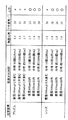
図13は本発明の実施例とその性能を示す。 FIG. 13 shows an embodiment of the present invention and its performance.
第1の光学要素としてはPET基材上にUV硬化性のアクリル樹脂でシリンドリカルレンズを作成した。もしくはPET基材上にUV硬化性のアクリル樹脂でプリズムを形成した。 As a first optical element, a cylindrical lens was made of UV curable acrylic resin on a PET substrate. Alternatively, prisms were formed on a PET substrate with UV curable acrylic resin.
プリズムシートの裏面にUV硬化性の接着剤を塗布し、粒子93として直径1mmで白色インキで彩色したガラスビーズもしくは樹脂ビーズを散布したのちUVで硬化させた。ビーズとプリズムシートの接触部分の面の最大直径は、散布した後硬化させるまでの時間で調整し、300um以下に調整したものと300umより大きいものを含むように調整したものを作成した。散布量にも差をつけ、分布はサンプルを作成してから面積あたりのビーズ数を数えた。
A UV curable adhesive was applied to the back surface of the prism sheet, and glass beads or resin beads colored with white ink having a diameter of 1 mm were sprayed as
シリンドリカルレンズシートは特開2005−37694号公報にあるように、白色の光反射部92Bと光透過部92Aとからなる反射層92を形成した。あらかじめ転写箔の基材上に離型剤を散布し、パターニングと無関係に転写させることで橋かけ部94を作成した。散布の際の液滴量を変化させることで300um以下に調整したものと300umより大きいものを含むように調整したものを作成した。散布量にも差をつけ、分布はサンプルを作成してから面積あたりのパターニング外の橋かけ部94を数えた。
As described in JP-A-2005-37694, the cylindrical lens sheet is formed with a
上記のように作成した試料を液晶ディスプレイに組込み、輝度及び画像の表示状態を確認した。
輝度は作成した光学シートを組み込んだ状態と、参照として光学シートのみを抜いた状態とを比べて比率にて表記した。
図13に判定結果を示す。
粒子93または橋かけ部94とプリズムシートの接触部分の面の大きさが300umを越えると、画像にムラとして認識される。300um以内のものはムラとして認識されなかった。
また、粒子93または橋かけ部94の数が増えると半値角が狭まり輝度が上昇し、総合的な光学特性が調整可能であった。また、使用した粒子93または橋かけ部94の種類による違いは見られなかった。
The sample prepared as described above was incorporated into a liquid crystal display, and the brightness and image display state were confirmed.
The luminance is expressed as a ratio by comparing the state in which the prepared optical sheet is incorporated with the state in which only the optical sheet is removed as a reference.
FIG. 13 shows the determination result.
When the size of the surface of the contact portion between the
Further, when the number of the
なお、今回使用した組合せは光学シートの一例であり、本発明はかかる構成のみに限定されるものではない。 The combination used this time is an example of an optical sheet, and the present invention is not limited to such a configuration.
上述したように、本発明によれば光学シートにおいて出射光が部分的に遮蔽もしくは反射されることを特徴とすることで、第1の光学要素の形状を変更せずに光学特性が調整可能な光学シートを提供することが可能になる。 As described above, according to the present invention, the emitted light is partially shielded or reflected by the optical sheet, so that the optical characteristics can be adjusted without changing the shape of the first optical element. An optical sheet can be provided.
26 拡散板
27 反射板
38 光学シート
40 バックライトユニット
44 レンズ部
46 開口部
48 ストライプ状のパターンからなる反射材
70 部材
72 単位プリズム
80 拡散フィルムもしくはDBEF
81 プリズムシートもしくは光学フィルム
82 拡散フィルム
83 拡散板
84 光源
85 ランプハウス
90 第1の光学要素
91 基材
92 反射層
93 粒子
94 橋かけ部
26
81 Prism sheet or optical film 82
Claims (11)
前記他方の面に、前記一方の面から入射した光を、その出射方向,範囲,色,輝度分布の少なくとも何れかを制御する第1の光学要素が設けられている光学シートにおいて、
前記一方の面に、反射性または遮光性を有する第2の光学要素が設けられている、
ことを特徴とする光学シート。 Having one surface in the thickness direction and the other surface;
In the optical sheet provided with the first optical element that controls at least one of the emission direction, range, color, and luminance distribution of the light incident from the one surface on the other surface,
A second optical element having a reflective property or a light shielding property is provided on the one surface.
An optical sheet characterized by that.
ことを特徴とする請求項1記載の光学シート。 The second optical element is composed of a large number of particles having reflectivity or light shielding properties provided on the one surface.
The optical sheet according to claim 1.
前記一方の面に反射層が設けられ、
前記反射層は、前記レンズ部の非集光領域に位置する光反射部と、残りの領域に位置する光透過部とを含んで構成され、
さらに、光を反射する材料から構成され前記光透過部を横切って前記光反射部相互を接続する橋かけ部が設けられ、
前記第2の光学要素は、前記橋かけ部で構成されている、
ことを特徴とする請求項1記載の光学シート。 The first optical element is a lens unit composed of a convex cylindrical lens group or a hemispherical convex lens group,
A reflective layer is provided on the one surface;
The reflective layer includes a light reflecting portion located in a non-condensing region of the lens portion and a light transmitting portion located in the remaining region,
Furthermore, a bridge portion is provided that is made of a material that reflects light and connects the light reflecting portions to each other across the light transmitting portion,
The second optical element is composed of the bridge portion.
The optical sheet according to claim 1.
前記一方の面に反射層が設けられ、
前記反射層は、前記プリズムの延伸方向と並列した光反射部と、前記光反射部以外の領域に位置する光透過部とを含んで構成され、
さらに、光を反射する材料から構成され前記光透過部を横切って前記光反射部相互を接続する橋かけ部が設けられ、
前記第2の光学要素は、前記橋かけ部で構成されている、
ことを特徴とする請求項1記載の光学シート。 The first optical element is a prism sheet in which a plurality of prisms are formed in parallel.
A reflective layer is provided on the one surface;
The reflective layer is configured to include a light reflecting part in parallel with the extending direction of the prism, and a light transmitting part located in a region other than the light reflecting part,
Furthermore, a bridge portion is provided that is made of a material that reflects light and connects the light reflecting portions to each other across the light transmitting portion,
The second optical element is composed of the bridge portion.
The optical sheet according to claim 1.
直下型光源と、請求項1乃至8に何れか1項記載の光学シートを少なくとも備え、
前記光学シートは、前記第1の光学要素を前記画像表示素子にむけて配置されている、
ことを特徴とするディスプレイ用バックライト・ユニット。 On the back of the image display element that defines the display image,
A direct light source, and at least an optical sheet according to any one of claims 1 to 8,
The optical sheet is disposed with the first optical element facing the image display element,
A backlight unit for displays.
エッジライト式光源と導光板からなる面光源と、請求項1乃至8に何れか1項記載の光学シートを少なくとも備え、
前記光学シートは、前記第1の光学要素を前記画像表示素子にむけて配置されている、
ことを特徴とするディスプレイ用バックライト・ユニット。 On the back of the image display element that defines the display image,
A surface light source comprising an edge light type light source and a light guide plate, and at least an optical sheet according to any one of claims 1 to 8,
The optical sheet is disposed with the first optical element facing the image display element,
A backlight unit for displays.
照明光が表示素子に入射する直前に光学シートが配置され、
前記光学シートは、前記照明光源側に位置する一方の面と、前記表示素子側に位置する他方の面とを有し、
前記他方の面に、前記一方の面から入射した光を、その出射方向,範囲,色,輝度分布の少なくとも何れかを制御する第1の光学要素が設けられ、
前記一方の面に、反射性または遮光性を有する第2の光学要素が設けられている、
ことを特徴とする表示装置。 Illumination light is emitted from an illumination light source disposed on the opposite side of the observer to a display element whose display pattern is defined according to transmission / non-transmission or transparency / scattering state in pixel units, In a display device configured to pass through to generate display light and emit it to the viewer side,
An optical sheet is arranged immediately before the illumination light enters the display element,
The optical sheet has one surface located on the illumination light source side and the other surface located on the display element side,
A first optical element that controls at least one of the emission direction, range, color, and luminance distribution of light incident from the one surface is provided on the other surface,
A second optical element having a reflective property or a light shielding property is provided on the one surface.
A display device characterized by that.
Priority Applications (1)
| Application Number | Priority Date | Filing Date | Title |
|---|---|---|---|
| JP2007046845A JP2008209713A (en) | 2007-02-27 | 2007-02-27 | Optical sheet, and backlight unit and display using the same |
Applications Claiming Priority (1)
| Application Number | Priority Date | Filing Date | Title |
|---|---|---|---|
| JP2007046845A JP2008209713A (en) | 2007-02-27 | 2007-02-27 | Optical sheet, and backlight unit and display using the same |
Publications (1)
| Publication Number | Publication Date |
|---|---|
| JP2008209713A true JP2008209713A (en) | 2008-09-11 |
Family
ID=39786065
Family Applications (1)
| Application Number | Title | Priority Date | Filing Date |
|---|---|---|---|
| JP2007046845A Pending JP2008209713A (en) | 2007-02-27 | 2007-02-27 | Optical sheet, and backlight unit and display using the same |
Country Status (1)
| Country | Link |
|---|---|
| JP (1) | JP2008209713A (en) |
-
2007
- 2007-02-27 JP JP2007046845A patent/JP2008209713A/en active Pending
Similar Documents
| Publication | Publication Date | Title |
|---|---|---|
| JP3985850B2 (en) | Optical sheet and backlight unit and display using the same | |
| CN101755166B (en) | Illumination device and display device | |
| JP2008527627A (en) | Optical film having a surface with a rounded structure | |
| JP2005221619A (en) | Optical sheet, back-light, and liquid crystal display device | |
| KR20010078303A (en) | Optical film | |
| JP5298569B2 (en) | Lens sheet, optical sheet for display, backlight unit using the same, and display device | |
| JP4039465B1 (en) | Optical sheet and backlight unit and display using the same | |
| JP4423933B2 (en) | Optical sheet and backlight unit and display using the same | |
| JP4792813B2 (en) | Optical sheet, optical sheet and backlight unit | |
| JP4501939B2 (en) | Optical sheet and backlight unit and display using the same | |
| JP2007213035A (en) | Optical sheet, and backlight unit and display using same | |
| JP2006208930A (en) | Optical sheet, and backlight unit and display using same | |
| JP2009086208A (en) | Optical sheet, backlight unit, and display device | |
| JP5217363B2 (en) | Lens sheet, optical sheet for display, backlight unit using the same, and display device | |
| JP4389938B2 (en) | Optical sheet and backlight unit and display using the same | |
| JP5104459B2 (en) | Optical member and backlight unit and display using it | |
| JP2010256431A (en) | Laminated resin sheet, and backlight unit and display device using the same | |
| JP5070891B2 (en) | Optical sheet and backlight unit and display using the same | |
| JP4956933B2 (en) | Optical sheet and backlight unit and display using the same | |
| JP2007256748A (en) | Optical sheet, backlight unit for display, and image displaying display | |
| JP2008209713A (en) | Optical sheet, and backlight unit and display using the same | |
| JP4506572B2 (en) | Optical sheet and backlight unit and display using the same | |
| JP2008249785A (en) | Optical sheet, backlight unit, and display device | |
| JP5109384B2 (en) | Display unit using optical sheet | |
| JP5194859B2 (en) | Optical sheet, backlight unit and display device |