JP2008198307A - Head slider and storage medium driving device - Google Patents
Head slider and storage medium driving device Download PDFInfo
- Publication number
- JP2008198307A JP2008198307A JP2007034502A JP2007034502A JP2008198307A JP 2008198307 A JP2008198307 A JP 2008198307A JP 2007034502 A JP2007034502 A JP 2007034502A JP 2007034502 A JP2007034502 A JP 2007034502A JP 2008198307 A JP2008198307 A JP 2008198307A
- Authority
- JP
- Japan
- Prior art keywords
- head element
- head
- top surface
- slider
- protrusion
- Prior art date
- Legal status (The legal status is an assumption and is not a legal conclusion. Google has not performed a legal analysis and makes no representation as to the accuracy of the status listed.)
- Pending
Links
Images


Classifications
-
- G—PHYSICS
- G11—INFORMATION STORAGE
- G11B—INFORMATION STORAGE BASED ON RELATIVE MOVEMENT BETWEEN RECORD CARRIER AND TRANSDUCER
- G11B5/00—Recording by magnetisation or demagnetisation of a record carrier; Reproducing by magnetic means; Record carriers therefor
- G11B5/127—Structure or manufacture of heads, e.g. inductive
- G11B5/31—Structure or manufacture of heads, e.g. inductive using thin films
- G11B5/3109—Details
- G11B5/313—Disposition of layers
- G11B5/3133—Disposition of layers including layers not usually being a part of the electromagnetic transducer structure and providing additional features, e.g. for improving heat radiation, reduction of power dissipation, adaptations for measurement or indication of gap depth or other properties of the structure
-
- G—PHYSICS
- G11—INFORMATION STORAGE
- G11B—INFORMATION STORAGE BASED ON RELATIVE MOVEMENT BETWEEN RECORD CARRIER AND TRANSDUCER
- G11B5/00—Recording by magnetisation or demagnetisation of a record carrier; Reproducing by magnetic means; Record carriers therefor
- G11B5/48—Disposition or mounting of heads or head supports relative to record carriers ; arrangements of heads, e.g. for scanning the record carrier to increase the relative speed
- G11B5/58—Disposition or mounting of heads or head supports relative to record carriers ; arrangements of heads, e.g. for scanning the record carrier to increase the relative speed with provision for moving the head for the purpose of maintaining alignment of the head relative to the record carrier during transducing operation, e.g. to compensate for surface irregularities of the latter or for track following
- G11B5/60—Fluid-dynamic spacing of heads from record-carriers
- G11B5/6005—Specially adapted for spacing from a rotating disc using a fluid cushion
- G11B5/6011—Control of flying height
- G11B5/6064—Control of flying height using air pressure
-
- G—PHYSICS
- G11—INFORMATION STORAGE
- G11B—INFORMATION STORAGE BASED ON RELATIVE MOVEMENT BETWEEN RECORD CARRIER AND TRANSDUCER
- G11B5/00—Recording by magnetisation or demagnetisation of a record carrier; Reproducing by magnetic means; Record carriers therefor
- G11B5/40—Protective measures on heads, e.g. against excessive temperature
Landscapes
- Physics & Mathematics (AREA)
- Electromagnetism (AREA)
- Engineering & Computer Science (AREA)
- Manufacturing & Machinery (AREA)
- Adjustment Of The Magnetic Head Position Track Following On Tapes (AREA)
- Magnetic Heads (AREA)
Abstract
Description
本発明は、例えばハードディスク駆動装置(HDD)といった記憶媒体駆動装置に組み込まれるヘッドスライダに関し、特に、ヘッド素子に関連付けられて非磁性膜に埋め込まれるヒーターを備えるヘッドスライダに関する。 The present invention relates to a head slider incorporated in a storage medium drive device such as a hard disk drive (HDD), and more particularly to a head slider including a heater associated with a head element and embedded in a nonmagnetic film.
ヘッドスライダでは例えばAl2O3−TiC(アルチック)製のスライダ本体にAl2O3(アルミナ)製の非磁性膜が積層される。非磁性膜にはヘッド素子およびヒーターが埋め込まれる。非磁性膜の表面には例えばダイヤモンドライクカーボン(DLC)製の保護膜が形成される。保護膜はヘッド素子に覆い被さる。 In the head slider, for example, a nonmagnetic film made of Al 2 O 3 (alumina) is laminated on a slider body made of Al 2 O 3 —TiC (Altic). A head element and a heater are embedded in the nonmagnetic film. For example, a protective film made of diamond-like carbon (DLC) is formed on the surface of the nonmagnetic film. The protective film covers the head element.
ヒーターはヘッド素子内の薄膜コイルパターンを加熱する。薄膜コイルパターンの線膨張に基づきヘッド素子の読み出しギャップや書き込みギャップは磁気ディスクに接近することができる。こうしてヘッド素子の浮上量は薄膜コイルパターンの突き出し量に基づき設定される。 The heater heats the thin film coil pattern in the head element. Based on the linear expansion of the thin film coil pattern, the read gap and write gap of the head element can approach the magnetic disk. Thus, the flying height of the head element is set based on the protruding amount of the thin film coil pattern.
突き出し量の設定にあたっていわゆるゼロキャリブレーションは実施される。ゼロキャリブレーションでは徐々に薄膜コイルパターンの突き出し量は増やされる。保護膜が磁気ディスクに接触する際に薄膜コイルパターンの突き出し量は特定される。この突き出し量に基づき読み出し時や書き込み時の突き出し量は決定される。
ゼロキャリブレーションでは保護膜と磁気ディスクとが接触する。接触が繰り返されるにつれて保護膜は摩耗していく。摩耗に基づき保護膜の膜厚は減少する。その結果、保護膜はヘッド素子を十分に保護することができない。例えば温度や湿度が高い環境下ではヘッド素子は腐食してしまう。ヘッド素子の特性は劣化してしまう。 In zero calibration, the protective film contacts the magnetic disk. As the contact is repeated, the protective film wears. The film thickness of the protective film decreases due to wear. As a result, the protective film cannot sufficiently protect the head element. For example, the head element is corroded in an environment where the temperature and humidity are high. The characteristics of the head element are deteriorated.
本発明は、上記実状に鑑みてなされたもので、ヘッド素子の損傷を回避することができるヘッドスライダおよび記憶媒体駆動装置を提供することを目的とする。 The present invention has been made in view of the above circumstances, and an object thereof is to provide a head slider and a storage medium driving device capable of avoiding damage to the head element.
上記目的を達成するために、本発明によれば、スライダ本体と、スライダ本体の空気流出側端面に積層される絶縁性の非磁性膜と、媒体対向面に形成されてスライダ本体から非磁性膜まで延びるレールと、非磁性膜に埋め込まれ、レールの頂上面で前端を露出させるヘッド素子と、ヘッド素子に関連付けられて非磁性膜に埋め込まれ、レールの頂上面でヘッド素子を隆起させるヒーターと、レールの頂上面に被さる保護膜と、保護膜の表面から突き出し、ヘッド素子の隆起時に保護膜の頂上面よりも記憶媒体に近づく突起とを備えることを特徴とするヘッドスライダが提供される。 In order to achieve the above object, according to the present invention, a slider body, an insulating nonmagnetic film laminated on the air outflow side end surface of the slider body, and a nonmagnetic film formed on the medium facing surface from the slider body. A rail that extends to the head, the head element that is embedded in the nonmagnetic film and exposes the front end at the top surface of the rail, and a heater that is embedded in the nonmagnetic film in association with the head element and raises the head element on the top surface of the rail; There is provided a head slider comprising: a protective film covering the top surface of the rail; and a protrusion protruding from the surface of the protective film and closer to the storage medium than the top surface of the protective film when the head element is raised.
こうしたヘッドスライダではいわゆるゼロキャリブレーションが実施される。ヒーターの働きでレールの頂上面でヘッド素子は隆起する。レールの頂上面には保護膜が被さる。保護膜の表面から突起が突き出る。ヘッド素子の隆起時に突起は保護膜の頂上面よりも記憶媒体に近づく。突起および記憶媒体の接触時、保護膜の頂上面および記憶媒体の接触は確実に回避される。ヘッド素子の前端で保護膜の摩耗は回避される。ヘッド素子の損傷は確実に阻止される。 In such a head slider, so-called zero calibration is performed. The head element is raised on the top surface of the rail by the action of the heater. A protective film covers the top surface of the rail. A protrusion protrudes from the surface of the protective film. When the head element is raised, the protrusion is closer to the storage medium than the top surface of the protective film. When the projection and the storage medium come into contact with each other, the contact between the top surface of the protective film and the storage medium is reliably avoided. Wear of the protective film is avoided at the front end of the head element. Damage to the head element is reliably prevented.
こういったヘッドスライダでは、保護膜の表面には1対の突起が区画されればよい。突起はスライダ本体の空気流出側端面に平行に所定の間隔で配置されればよい。こうした1対の突起は記憶媒体に安定して接触することができる。このとき、突起は、ヘッド素子に含まれる書き込みヘッド素子の両側に配置されればよい。突起は、ヘッド素子の隆起時に規定される頂点の両側に配置されればよい。 In such a head slider, a pair of protrusions may be defined on the surface of the protective film. The protrusions may be arranged at a predetermined interval in parallel with the air outflow side end surface of the slider body. Such a pair of protrusions can stably contact the storage medium. At this time, the protrusions may be disposed on both sides of the write head element included in the head element. The protrusions may be disposed on both sides of the apex defined when the head element is raised.
ヒーターはヘッド素子の両側に配置されればよい。非磁性膜には、第1線膨張係数の第1領域と、ヘッド素子の両側に区画され、第1線膨張係数よりも大きい第2線膨張係数の第2領域とが区画されればよい。こうしたヒーターや第2領域の働きでヘッド素子の隆起の幅は増大する。保護パッド同士の間隔は増大する。保護パッドは安定して記憶媒体に接触することができる。こういったヘッドスライダは例えば記憶媒体駆動装置に組み込まれる。 The heater may be disposed on both sides of the head element. The nonmagnetic film only needs to be divided into a first region having a first linear expansion coefficient and a second region having a second linear expansion coefficient that is defined on both sides of the head element and is larger than the first linear expansion coefficient. The width of the raised head element is increased by the action of the heater and the second region. The distance between the protective pads increases. The protective pad can stably contact the storage medium. Such a head slider is incorporated in a storage medium driving device, for example.
以上のように本発明によれば、ヘッド素子の損傷を回避することができるヘッドスライダおよび記憶媒体駆動装置が提供される。 As described above, according to the present invention, a head slider and a storage medium driving device that can avoid damage to the head element are provided.
以下、添付図面を参照しつつ本発明の一実施形態を説明する。 Hereinafter, an embodiment of the present invention will be described with reference to the accompanying drawings.
図1は本発明に係る記憶媒体駆動装置の一具体例すなわちハードディスク駆動装置(HDD)11の内部構造を概略的に示す。このハードディスク駆動装置11は筐体すなわちハウジング12を備える。ハウジング12は箱形のベース13およびカバー(図示されず)から構成される。ベース13は例えば平たい直方体の内部空間すなわち収容空間を区画する。ベース13は例えばアルミニウムといった金属材料から鋳造に基づき成形されればよい。カバーはベース13の開口に結合される。カバーとベース13との間で収容空間は密閉される。カバーは例えばプレス加工に基づき1枚の板材から成形されればよい。
FIG. 1 schematically shows an internal structure of a hard disk drive (HDD) 11 as a specific example of a storage medium drive according to the present invention. The
収容空間には、記憶媒体としての1枚以上の磁気ディスク14が収容される。磁気ディスク14はスピンドルモータ15の回転軸に装着される。スピンドルモータ15は例えば5400rpmや7200rpm、10000rpm、15000rpmといった高速度で磁気ディスク14を回転させることができる。磁気ディスク14は垂直磁気記憶媒体を構成する。
In the accommodation space, one or more
収容空間にはキャリッジ16がさらに収容される。キャリッジ16はキャリッジブロック17を備える。キャリッジブロック17は、垂直方向に延びる支軸18に回転自在に連結される。キャリッジブロック17には、支軸18から水平方向に延びる複数のキャリッジアーム19が区画される。キャリッジブロック17は例えば押し出し成型に基づきアルミニウムから成型されればよい。
A
個々のキャリッジアーム19の先端にはヘッドサスペンション21が取り付けられる。ヘッドサスペンション21はキャリッジアーム19の先端から前方に延びる。ヘッドサスペンション21の先端にはフレキシャが張り合わせられる。フレキシャにはいわゆるジンバルばねが区画される。こうしたジンバルばねの働きで浮上ヘッドスライダ22はヘッドサスペンション21に対してその姿勢を変化させることができる。後述されるように、浮上ヘッドスライダ22にはヘッド素子すなわち電磁変換素子が搭載される。
A head suspension 21 is attached to the tip of each
磁気ディスク14の回転に基づき磁気ディスク14の表面で気流が生成されると、気流の働きで浮上ヘッドスライダ22には正圧すなわち浮力および負圧が作用する。浮力および負圧とヘッドサスペンション21の押し付け力とが釣り合うことで磁気ディスク14の回転中に比較的に高い剛性で浮上ヘッドスライダ22は浮上し続けることができる。
When an air flow is generated on the surface of the
こういった浮上ヘッドスライダ22の浮上中にキャリッジ16が支軸18回りで回転すると、浮上ヘッドスライダ22は磁気ディスク14の半径線に沿って移動することができる。その結果、浮上ヘッドスライダ22上の電磁変換素子は最内周記録トラックと最外周記録トラックとの間でデータゾーンを横切ることができる。こうして浮上ヘッドスライダ22上の電磁変換素子は目標の記録トラック上に位置決めされる。
When the
キャリッジブロック17には例えばボイスコイルモータ(VCM)23といった動力源が接続される。このVCM23の働きでキャリッジブロック17は支軸18回りで回転することができる。こうしたキャリッジブロック17の回転に基づきキャリッジアーム19およびヘッドサスペンション21の揺動は実現される。
For example, a power source such as a voice coil motor (VCM) 23 is connected to the
図1から明らかなように、キャリッジブロック17上には、フレキシブルプリント基板ユニット25が配置される。フレキシブルプリント基板ユニット25は、フレキシブルプリント基板26に実装されるヘッドIC(集積回路)27を備える。ヘッドIC27は電磁変換素子の読み出しヘッド素子および書き込みヘッド素子に接続される。接続にあたってフレキシブルプリント基板28が用いられる。フレキシブルプリント基板28は個々のフレキシャから連続する。フレキシブルプリント基板28はフレキシブルプリント基板ユニット25に接続される。
As is clear from FIG. 1, the flexible printed
磁気情報の読み出し時には、このヘッドIC27から電磁変換素子の読み出しヘッド素子に向けてセンス電流が供給される。読み出しヘッド素子には例えばCPP構造読み取り素子が用いられる。同様に、磁気情報の書き込み時には、ヘッドIC27から電磁変換素子の書き込みヘッド素子に向けて書き込み電流が供給される。書き込みヘッド素子には例えば単磁極ヘッド素子が用いられる。センス電流の電流値は特定の値に設定される。ヘッドIC27には、収容空間内に配置される小型の回路基板29や、ベース13の底板の裏側に取り付けられるプリント回路基板(図示されず)から電流が供給される。
When reading magnetic information, a sense current is supplied from the
図2は一具体例に係る浮上ヘッドスライダ22を示す。この浮上ヘッドスライダ22は、例えば平たい直方体に形成されるスライダ本体31を備える。スライダ本体31の空気流出端面には非磁性膜すなわち素子内蔵膜32が積層される。この素子内蔵膜32に前述の電磁変換素子33が組み込まれる。電磁変換素子33の詳細は後述される。スライダ本体31は例えばAl2O3−TiC(アルチック)といった硬質の非磁性材料から形成されればよい。素子内蔵膜32は例えばAl2O3(アルミナ)といった比較的に軟質の絶縁非磁性材料から形成されればよい。
FIG. 2 shows a flying
浮上ヘッドスライダ22は媒体対向面すなわち浮上面34で磁気ディスク14に向き合う。浮上面34には平坦なベース面35すなわち基準面が規定される。磁気ディスク14が回転すると、スライダ本体31の前端から後端に向かって浮上面34には気流36が作用する。
The flying
浮上面34には、前述の気流36の上流側すなわち空気流入側でベース面35から立ち上がる1筋のフロントレール37が形成される。フロントレール37はベース面35の空気流入端に沿ってスライダ幅方向に延びる。同様に、浮上面34には、気流の下流側すなわち空気流出側でベース面35から立ち上がるリアレール38が形成される。リアレール38はスライダ幅方向の中央位置に配置される。リアレール38はスライダ本体31から素子内蔵膜32まで延びる。
A
浮上面34には、空気流出側でベース面35から立ち上がる左右1対の補助リアレール39、39がさらに形成される。補助リアレール39、39はベース面35の左右の縁に沿ってそれぞれ配置される。その結果、補助リアレール39、39同士はスライダ幅方向に間隔を空けて配置される。補助リアレール39、39同士の間にリアレール38は配置される。
On the
フロントレール37、リアレール38および補助リアレール39、39の頂上面にはいわゆる空気軸受け面(ABS)41、42、43が規定される。空気軸受け面41、42、43の空気流入端は段差44、45、46でレール37、38、39の頂上面に接続される。磁気ディスク14の回転に基づき生成される気流36は浮上面34に受け止められる。このとき、段差44、45、46の働きで空気軸受け面41、42、43には比較的に大きな正圧すなわち浮力が生成される。しかも、フロントレール37の後方すなわち背後には大きな負圧が生成される。これら浮力および負圧のバランスに基づき浮上ヘッドスライダ22の浮上姿勢は確立される。なお、浮上ヘッドスライダ22の形態はこういった形態に限られるものではない。
So-called air bearing surfaces (ABS) 41, 42, 43 are defined on the top surfaces of the
空気軸受け面41、42、43には例えば保護膜(図示されず)が積層される。空気軸受け面42の空気流出側でリアレール38の頂上面は保護膜で覆われる。図3に示されるように、電磁変換素子33はスライダ幅方向に延びる。電磁変換素子33はリアレール38の頂上面でCPP構造読み取り素子47の前端や単磁極ヘッド素子48の前端を露出させる。保護膜にはその表面から立ち上がる1対の突起すなわち保護パッド49、49が形成される。保護パッド49はスライダ幅方向に電磁変換素子33の左右両側に配置される。すなわち、保護パッド49は、スライダ本体31の空気流出側端面に平行に所定の間隔で配置される。図4を併せて参照し、保護膜51はCPP構造読み取り素子47の前端や単磁極ヘッド素子48の前端に被さる。保護パッド49は、スライダ幅方向に例えば単磁極ヘッド素子48の両側に配置される。保護膜51や保護パッド49には例えばDLC(ダイヤモンドライクカーボン)が用いられればよい。
For example, a protective film (not shown) is laminated on the air bearing surfaces 41, 42, 43. The top surface of the
図5は電磁変換素子33の様子を詳細に示す。CPP構造読み取り素子47は、周知の通り、磁気ディスク14から作用する磁界に応じて変化する抵抗に基づき2値情報を検出することができる。単磁極ヘッド素子48は、周知の通り、例えば後述の薄膜コイルパターンで生起される磁界を利用して磁気ディスク14に2値情報を書き込むことができる。CPP構造読み取り素子47および薄膜磁気ヘッド素子48はAl2O3膜57とAl2O3膜58との間に挟み込まれる。Al2O3膜57は前述の素子内蔵膜32の上側半層すなわちオーバーコート膜を構成する。Al2O3膜58は素子内蔵膜32の下側半層すなわちアンダーコート膜を構成する。
FIG. 5 shows the state of the
CPP構造読み取り素子47は例えばスピンバルブ膜やトンネル接合膜といった磁気抵抗効果膜59を備える。磁気抵抗効果膜59は上側電極61および下側電極62に挟み込まれる。上側電極61および下側電極62は、スライダ本体31の表面で露出する前端で磁気抵抗効果膜59の上側境界面および下側境界面にそれぞれ接触する。上側電極61および下側電極62の働きで磁気抵抗効果膜59にセンス電流は供給される。上側電極61および下側電極62は導電性を備えるだけでなく同時に軟磁性を備えてもよい。上側電極61および下側電極62が例えばパーマロイ(NiFe合金)といった導電性の軟磁性体で構成されると、上側電極61および下側電極62は同時にCPP構造読み取り素子47の上部および下部シールド層として機能することができる。こうして上側電極61および下側電極62は読み出しギャップを規定する。
The CPP
単磁極ヘッド素子48は、空気軸受け面42で露出する主磁極64および補助磁極65を備える。主磁極64および補助磁極65は例えばパーマロイといった導電性の軟磁性体から構成されればよい。主磁極64および補助磁極65は協働して単磁極ヘッド素子48の磁性コアを構成する。主磁極64および補助磁極65の間には例えばAl2O3製の非磁性ギャップ層66が挟み込まれる。後述の薄膜コイルパターンで磁界が生起されると、非磁性ギャップ層66の働きで、主磁極64から補助磁極65に向かって磁束が漏れ出る。漏れ出る磁束がギャップ磁界すなわち記録磁界を形成する。こうして主磁極64および補助磁極65は書き込みギャップを規定する。
The single magnetic
図6を併せて参照し、主磁極64は、上側電極61上で任意の基準平面67に沿って広がる。この基準平面67はAl2O3製の非磁性層68の表面で規定される。非磁性層68は上側電極61上に均一な厚みで積層形成されればよい。非磁性層68は上側電極61と主磁極64との間で磁気的な結合を断ち切る。
Referring also to FIG. 6, the main magnetic pole 64 extends along an
非磁性ギャップ層66上には薄膜コイルパターン71が配置される。薄膜コイルパターン71は1平面に沿って渦巻き状に広がる。薄膜コイルパターン71は非磁性ギャップ層66上で絶縁層72に埋め込まれる。絶縁層72の表面に前述の補助磁極65が形成される。補助磁極65は薄膜コイルパターン71の中心位置で主磁極64に磁気的に連結される。薄膜コイルパターン71に電流が供給されると、主磁極64および補助磁極65に磁束が流通する。
A thin
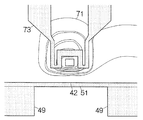
素子内蔵膜32には電磁変換素子33に関連づけられてヒーターが組み込まれる。このヒーターは、例えば絶縁層72に埋め込まれる電熱線73で構成される。電熱線73は1平面に沿って広がる。図7に示されるように、電熱線73は薄膜コイルパターン71の中心位置を迂回しつつ延びる。薄膜コイルパターン71は比較的に大きな線膨張係数を有することから、電熱線73に電力が供給されると、電熱線73の熱に基づき薄膜コイルパターン71は膨張する。その結果、図8に示されるように、リアレール38の頂上面で薄膜コイルパターン71すなわち単磁極ヘッド素子48は素子内蔵膜32の表面で隆起する。いわゆる突き出し74が形成される。こうしてCPP構造読み取り素子47および単磁極ヘッド素子48は磁気ディスク14に向かって変位する。例えば単磁極ヘッド素子48の突き出し量に応じて単磁極ヘッド素子48の浮上量は決定される。このとき、図9に示されるように、保護パッド49、49は突き出し74の頂点の両側に配置される。突き出し74の頂点は保護膜51の頂上面に規定される。保護パッド49は保護膜51の頂上面よりも必ず磁気ディスク14に近づく。
A heater is incorporated in the element built-in
図10に示されるように、ヘッドIC27にはプリアンプ回路81、電流供給回路82および電力供給回路83が組み込まれる。プリアンプ回路81はCPP構造読み取り素子47に接続される。プリアンプ回路81からCPP構造読み取り素子47に向かってセンス電流は供給される。センス電流の電流値は一定値に維持される。
As shown in FIG. 10, a preamplifier circuit 81, a current supply circuit 82, and a
電流供給回路82は単磁極ヘッド素子48に接続される。電流供給回路82から単磁極ヘッド素子48に書き込み電流は供給される。供給された書き込み電流に基づき単磁極ヘッド素子48で磁界が生成される。
The current supply circuit 82 is connected to the single
電熱線73には電力供給回路83が接続される。電力供給回路83は電熱線73に所定の電力を供給する。電力の供給に応じて電熱線73は発熱する。電熱線73の温度は電力量で決定される。すなわち、電力量に基づき突き出し74の突き出し量は制御されることができる。
A
ヘッドIC27には制御回路(ハードディスクコントローラ)84が接続される。制御回路84はヘッドIC27に対してセンス電流や書き込み電流、電力の供給を指示する。同時に、制御回路84はセンス電流の電圧を検知する。検知に先立ってプリアンプ回路81はセンス電流の電圧を増幅する。
A control circuit (hard disk controller) 84 is connected to the
制御回路84はプリアンプ回路81の出力に基づき2値情報を判別する。同時に、制御回路84はプリアンプ回路81の出力に基づき電圧値の「揺れ」を検知する。例えば突き出し74の形成に応じて保護パッド49が磁気ディスク14に接触すると、浮上ヘッドスライダ22は微小な振動に曝される。このとき、センス電流の電圧値には「揺れ」が生じる。こういった「揺れ」が制御回路84で検出される。
The control circuit 84 determines binary information based on the output of the preamplifier circuit 81. At the same time, the control circuit 84 detects “fluctuation” of the voltage value based on the output of the preamplifier circuit 81. For example, when the
この制御回路84は所定のソフトウェアプログラムに従ってプリアンプ回路81、電流供給回路82および電力供給回路83の動作を制御する。ソフトウェアプログラムは例えばメモリ85に格納されればよい。こういったソフトウェアプログラムに基づき後述のゼロキャリブレーションは実施される。実施にあたって必要なデータは同様にメモリ85に格納されればよい。メモリ85には他の記憶媒体からソフトウェアプログラムやデータが移行されればよい。制御回路84やメモリ85は例えば回路基板29上に実装されればよい。
The control circuit 84 controls operations of the preamplifier circuit 81, the current supply circuit 82, and the
このハードディスク駆動装置11では磁気情報の読み出しや書き込みに先立って単磁極ヘッド素子48の突き出し量が設定される。この突き出し量の設定にあたっていわゆるゼロキャリブレーションが実施される。ゼロキャリブレーションでは、保護パッド49が磁気ディスク14に接触する際に突き出し74の突き出し量が測定される。こうした接触時の突き出し量に基づき読み出し時や書き込み時の突き出し74の突き出し量は設定される。こうして読み出し時や書き込み時に突き出し74の突き出し量が設定されると、電磁変換素子すなわち単磁極ヘッド素子48は予め決められた浮上量で磁気ディスク14の表面から浮上することができる。こういったゼロキャリブレーションは例えばハードディスク駆動装置11の起動のたびに実施されればよい。
In the
ゼロキャリブレーションの実施にあたって制御回路84は所定のソフトウェアプログラムを実行する。ソフトウェアプログラムが実行されると、制御回路84はハードディスク駆動装置11の初期設定を実施する。この初期設定で制御回路84はスピンドルモータ15に駆動を命じる。磁気ディスク14は所定の回転速度で回転する。同時に、制御回路84はVCM23に駆動を命じる。キャリッジ16は支軸18回りで揺動する。その結果、浮上ヘッドスライダ22は磁気ディスク14の表面に向き合わせられる。浮上ヘッドスライダ22は所定の浮上高さで磁気ディスク14から浮上する。加えて、制御回路84はヘッドIC27に電流を供給する。制御回路84はプリアンプ回路81の出力を監視する。すなわち、制御回路84はセンス電流の電圧値を観察する。このとき、電力供給回路83は電力の供給を保留する。
In performing the zero calibration, the control circuit 84 executes a predetermined software program. When the software program is executed, the control circuit 84 performs initial setting of the
初期設定が完了すると、制御回路84は電力供給回路83に指令信号を供給する。制御回路84は規定の増加量で突き出し74の突き出し量を増加させる。指令信号の受信に応じて電力供給回路83は増加後の突き出し量に見合った電力量の電力を電熱線73に供給する。増加量は例えば0.1nmに設定されればよい。電力量は例えば単磁極ヘッド素子48の線膨張係数に基づき予め設定されればよい。こうして突き出し74の突き出し量が増加すると、制御回路84は保護パッド49および磁気ディスク14の「接触」を判定する。判定にあたって制御回路84はセンス電流の電圧値に出現する前述の「揺れ」の有無を観察する。
When the initial setting is completed, the control circuit 84 supplies a command signal to the
こうして「揺れ」が観察されるまで、制御回路84は規定の増加量で突き出し74の突き出し量を増加させる。突き出し74の突き出しに基づき保護パッド49は突き出し74の頂点よりも常に磁気ディスク14に近づく。その結果、図11に示されるように、保護パッド49は磁気ディスク14に接触する。図12を併せて参照し、保護パッド49、49同士の間で突き出し74すなわち保護膜51の頂上面および磁気ディスク14の接触は回避される。こうして「揺れ」が観察される。制御回路84は保護パッド49および磁気ディスク14の間で接触を判断する。制御回路84は突き出し74の突き出し量を特定する。こうして接触時の突き出し量は特定される。特定された突き出し量は例えばメモリ85に保存される。ただし、接触時に保護パッド49の先端と突き出し74の頂上との間には所定の距離が特定される。こうした距離は単磁極ヘッド素子48の浮上量の設定にあたって参照される。距離は例えばシミュレーションに基づき予め算出されればよい。こうしてゼロキャリブレーションは完了する。
In this way, the control circuit 84 increases the protrusion amount of the
以上のようなハードディスク駆動装置11では、突き出し74の突き出し量の設定にあたって保護パッド49が磁気ディスク14に接触する。保護パッド49、49同士の間で保護膜51の頂上面および磁気ディスク14の接触は回避される。突き出し74の頂上で保護膜51の摩耗は確実に阻止される。保護膜51は電磁変換素子33を十分に保護することができる。電磁変換素子33の腐食は確実に回避される。
In the
図13に示されるように、浮上ヘッドスライダ22では電熱線73の幅が増大してもよい。電熱線73は、蛇行しつつ延びる蛇行領域73aを区画する。蛇行領域73は薄膜コイルパターン71すなわち単磁極ヘッド素子48の両側に配置される。蛇行領域73aの蛇行に基づき電熱線73には薄膜コイルパターン71の両側で十分な長さが確保される。こうした電熱線73によれば、図14に示されるように、突き出し74は電磁変換素子33の幅方向に広がる。その結果、保護パッド49同士の間隔は増大する。保護パッド49は磁気ディスク14に安定して接触することができる。
As shown in FIG. 13, the width of the
このとき、図15に示されるように、例えば非磁性層68には、第1領域68aおよび第2領域68bが区画される。第2領域68bの線膨張係数は第1領域68aの線膨張係数の大きい。第2領域68bは、例えば電熱線73の蛇行領域73aに対応する位置に区画されればよい。すなわち、第2領域68bは電磁変換素子33の両側に配置される。第2領域68bには例えばCuといった非磁性材料が用いられればよい。第2領域68bの働きで突き出し74の幅方向の広がりは促進される。前述と同様に、保護パッド49同士の間隔の増大に基づき保護パッド49は磁気ディスク14に安定して接触することができる。
At this time, as shown in FIG. 15, for example, the
以上のような浮上ヘッドスライダ22では、保護パッド49、49は必ずしもスライダ本体31の空気流出側端面に平行に配置されなくてもよい。例えば一方の保護パッド49が空気流入側に偏倚して配置されるとともに、他方の保護パッド49が空気流出側に偏倚して配置されてもよい。その他、保護パッド49は、例えば突き出し74の周囲を途切れなく取り囲む突壁で構成されてもよい。このとき、突壁には切れ込みが形成されてもよい。なお、保護パッド49の形状はこういった形状に限られるものではない。保護パッド49の形状は適宜変更されることができる。
In the flying
(付記1) スライダ本体と、スライダ本体の空気流出側端面に積層される絶縁性の非磁性膜と、媒体対向面に形成されてスライダ本体から非磁性膜まで延びるレールと、非磁性膜に埋め込まれ、レールの頂上面で前端を露出させるヘッド素子と、ヘッド素子に関連付けられて非磁性膜に埋め込まれ、レールの頂上面でヘッド素子を隆起させるヒーターと、レールの頂上面に被さる保護膜と、保護膜の表面から突き出し、ヘッド素子の隆起時に保護膜の頂上面よりも記憶媒体に近づく突起とを備えることを特徴とするヘッドスライダ。 (Supplementary note 1) Slider body, insulating nonmagnetic film laminated on the air outflow side end surface of the slider body, rail formed on the medium facing surface and extending from the slider body to the nonmagnetic film, and embedded in the nonmagnetic film A head element that exposes the front end at the top surface of the rail, a heater that is associated with the head element and embedded in the nonmagnetic film, and that projects the head element at the top surface of the rail, and a protective film that covers the top surface of the rail And a protrusion that protrudes from the surface of the protective film and is closer to the storage medium than the top surface of the protective film when the head element is raised.
(付記2) 付記1に記載のヘッドスライダにおいて、1対の前記突起は前記スライダ本体の空気流出側端面に平行に所定の間隔で配置されることを特徴とするヘッドスライダ。 (Additional remark 2) The head slider of Additional remark 1 WHEREIN: A pair of said protrusion is arrange | positioned in parallel with the air outflow side end surface of the said slider main body at predetermined intervals, The head slider characterized by the above-mentioned.
(付記3) 付記2に記載のヘッドスライダにおいて、前記突起は、前記ヘッド素子に含まれる書き込みヘッド素子の両側に配置されることを特徴とするヘッドスライダ。 (Additional remark 3) The head slider of Additional remark 2 WHEREIN: The said protrusion is arrange | positioned at the both sides of the write head element contained in the said head element, The head slider characterized by the above-mentioned.
(付記4) 付記2に記載のヘッドスライダにおいて、前記ヒーターは前記ヘッド素子の両側に配置されることを特徴とするヘッドスライダ。 (Additional remark 4) The head slider of Additional remark 2 WHEREIN: The said heater is arrange | positioned at the both sides of the said head element, The head slider characterized by the above-mentioned.
(付記5) 付記2に記載のヘッドスライダにおいて、前記非磁性膜には、第1線膨張係数の第1領域と、前記ヘッド素子の両側に区画され、第1線膨張係数よりも大きい第2線膨張係数の第2領域とが区画されることを特徴とするヘッドスライダ。 (Supplementary Note 5) In the head slider according to Supplementary Note 2, the nonmagnetic film includes a first region of a first linear expansion coefficient and a second region that is partitioned on both sides of the head element and is larger than the first linear expansion coefficient. A head slider characterized in that a second region of a linear expansion coefficient is partitioned.
(付記6) 付記1に記載のヘッドスライダにおいて、前記突起は、前記ヘッド素子の隆起時に規定される頂点の両側に配置されることを特徴とするヘッドスライダ。 (Additional remark 6) The head slider of Additional remark 1 WHEREIN: The said protrusion is arrange | positioned at the both sides of the vertex prescribed | regulated at the time of the protrusion of the said head element, The head slider characterized by the above-mentioned.
(付記7) スライダ本体と、スライダ本体の空気流出側端面に積層される絶縁性の非磁性膜と、媒体対向面に形成されてスライダ本体から非磁性膜まで延びるレールと、非磁性膜に埋め込まれ、レールの頂上面で前端を露出させるヘッド素子と、ヘッド素子に関連付けられて非磁性膜に埋め込まれ、レールの頂上面でヘッド素子を隆起させるヒーターと、レールの頂上面に被さる保護膜と、保護膜の表面から突き出し、ヘッド素子の隆起時に保護膜の頂上面よりも記憶媒体に近づく突起とを備えることを特徴とする記憶媒体駆動装置。 (Supplementary note 7) Slider body, insulating nonmagnetic film laminated on the air outflow side end surface of the slider body, rail formed on the medium facing surface and extending from the slider body to the nonmagnetic film, and embedded in the nonmagnetic film A head element that exposes the front end at the top surface of the rail, a heater that is associated with the head element and embedded in the nonmagnetic film, and that projects the head element at the top surface of the rail, and a protective film that covers the top surface of the rail A storage medium driving device comprising: a protrusion protruding from the surface of the protective film, and a protrusion closer to the storage medium than the top surface of the protective film when the head element is raised.
(付記8) 付記7に記載の記憶媒体駆動装置において、1対の前記突起は前記スライダ本体の空気流出側端面に平行に所定の間隔で配置されることを特徴とする記憶媒体駆動装置。 (Supplementary note 8) The storage medium drive device according to supplementary note 7, wherein the pair of protrusions are arranged in parallel with the air outflow side end surface of the slider body at a predetermined interval.
(付記9) 付記8に記載の記憶媒体駆動装置において、前記突起は、前記ヘッド素子に含まれる書き込みヘッド素子の両側に配置されることを特徴とする記憶媒体駆動装置。 (Supplementary note 9) The storage medium drive device according to supplementary note 8, wherein the protrusions are arranged on both sides of a write head element included in the head element.
(付記10) 付記8に記載の記憶媒体駆動装置において、前記ヒーターは前記ヘッド素子の両側に配置されることを特徴とする記憶媒体駆動装置。 (Supplementary note 10) The storage medium drive device according to supplementary note 8, wherein the heater is disposed on both sides of the head element.
(付記11) 付記8に記載の記憶媒体駆動装置において、前記非磁性膜には、第1線膨張係数の第1領域と、前記ヘッド素子の両側に区画され、第1線膨張係数よりも大きい第2線膨張係数の第2領域とが区画されることを特徴とする記憶媒体駆動装置。 (Supplementary note 11) In the storage medium driving device according to supplementary note 8, the nonmagnetic film is partitioned on the first region of the first linear expansion coefficient and on both sides of the head element, and is larger than the first linear expansion coefficient. A storage medium driving device characterized in that a second region of a second linear expansion coefficient is partitioned.
(付記12) 付記7に記載の記憶媒体駆動装置において、前記突起は、前記ヘッド素子の隆起時に規定される頂点の両側に配置されることを特徴とする記憶媒体駆動装置。 (Supplementary note 12) The storage medium driving device according to supplementary note 7, wherein the protrusions are arranged on both sides of a vertex defined when the head element is raised.
11 記憶媒体駆動装置(ハードディスク駆動装置)、14 記憶媒体(磁気ディスク)、22 ヘッドスライダ(浮上ヘッドスライダ)、31 スライダ本体、32 非磁性膜(素子内蔵膜)、33 ヘッド素子(電磁変換素子)、38 レール(リアレール)、48 書き込みヘッド素子(単磁極ヘッド素子)、49 突起(保護パッド)、51 保護膜、68a 第1領域、68b 第2領域、73 ヒーター(電熱線)。
DESCRIPTION OF
Claims (6)
Priority Applications (2)
| Application Number | Priority Date | Filing Date | Title |
|---|---|---|---|
| JP2007034502A JP2008198307A (en) | 2007-02-15 | 2007-02-15 | Head slider and storage medium driving device |
| US12/029,276 US20080198510A1 (en) | 2007-02-15 | 2008-02-11 | Head slider and storage medium drive |
Applications Claiming Priority (1)
| Application Number | Priority Date | Filing Date | Title |
|---|---|---|---|
| JP2007034502A JP2008198307A (en) | 2007-02-15 | 2007-02-15 | Head slider and storage medium driving device |
Publications (1)
| Publication Number | Publication Date |
|---|---|
| JP2008198307A true JP2008198307A (en) | 2008-08-28 |
Family
ID=39706442
Family Applications (1)
| Application Number | Title | Priority Date | Filing Date |
|---|---|---|---|
| JP2007034502A Pending JP2008198307A (en) | 2007-02-15 | 2007-02-15 | Head slider and storage medium driving device |
Country Status (2)
| Country | Link |
|---|---|
| US (1) | US20080198510A1 (en) |
| JP (1) | JP2008198307A (en) |
Cited By (3)
| Publication number | Priority date | Publication date | Assignee | Title |
|---|---|---|---|---|
| JP2008262649A (en) * | 2007-04-13 | 2008-10-30 | Hitachi Ltd | Magnetic head slider |
| JP2011008906A (en) * | 2009-06-22 | 2011-01-13 | Seagate Technology Llc | Method and apparatus for operating data storage device and slider |
| US8916487B2 (en) | 2010-06-30 | 2014-12-23 | Hoya Corporation | Glass substrate for information recording medium |
Families Citing this family (6)
| Publication number | Priority date | Publication date | Assignee | Title |
|---|---|---|---|---|
| US8456643B2 (en) | 2010-05-24 | 2013-06-04 | Western Digital (Fremont), Llc | Method and system for mapping the shape of a head under operating conditions |
| US20130215534A1 (en) | 2012-02-17 | 2013-08-22 | Seagate Technology Llc | Slider edge features |
| US8897104B1 (en) | 2013-04-02 | 2014-11-25 | Western Digital (Fremont), Llc | Method and system for performing off-disk measurements of laser-induced NFT protrusion in a heat assisted magnetic recording transducer |
| US9165584B2 (en) * | 2013-07-09 | 2015-10-20 | Seagate Technology Llc | Air bearing surface having temperature/humidity compensation feature |
| US9153266B1 (en) | 2014-09-11 | 2015-10-06 | Western Digital Technologies, Inc. | Data storage device measuring laser protrusion fly height profile |
| US11830530B1 (en) | 2022-01-11 | 2023-11-28 | Seagate Technology Llc | Skew-independent close-point transducers |
Family Cites Families (2)
| Publication number | Priority date | Publication date | Assignee | Title |
|---|---|---|---|---|
| US5822153A (en) * | 1997-01-03 | 1998-10-13 | Censtor Corp. | Hard disk drive having contact write and recessed magnetorestive read head |
| US6975472B2 (en) * | 2003-09-12 | 2005-12-13 | Seagate Technology Llc | Head with heating element and control regime therefor |
-
2007
- 2007-02-15 JP JP2007034502A patent/JP2008198307A/en active Pending
-
2008
- 2008-02-11 US US12/029,276 patent/US20080198510A1/en not_active Abandoned
Cited By (3)
| Publication number | Priority date | Publication date | Assignee | Title |
|---|---|---|---|---|
| JP2008262649A (en) * | 2007-04-13 | 2008-10-30 | Hitachi Ltd | Magnetic head slider |
| JP2011008906A (en) * | 2009-06-22 | 2011-01-13 | Seagate Technology Llc | Method and apparatus for operating data storage device and slider |
| US8916487B2 (en) | 2010-06-30 | 2014-12-23 | Hoya Corporation | Glass substrate for information recording medium |
Also Published As
| Publication number | Publication date |
|---|---|
| US20080198510A1 (en) | 2008-08-21 |
Similar Documents
| Publication | Publication Date | Title |
|---|---|---|
| CN101727919B (en) | Method and system for controlling contact position during thermal fly height control touchdown | |
| JP5792869B2 (en) | Hard disk drive with contact detection using spin torque oscillator | |
| JP2008198307A (en) | Head slider and storage medium driving device | |
| US8125728B2 (en) | Disk drive, head-slider and method for controlling clearance of a read element and a write element in the disk drive | |
| US8169744B2 (en) | Slider having a lubricant-accumulation barrier | |
| KR20080039210A (en) | Head sliders and manufacturing methods thereof, and polishing apparatus for head sliders | |
| US20100226044A1 (en) | Head slider and storage medium driving device | |
| JP2008226439A (en) | Recording/reproducing head and its manufacturing method | |
| JP2007207307A (en) | Flying head slider and recording medium driving apparatus | |
| JP2009099219A (en) | Magnetic head | |
| JP2011129222A (en) | Magnetic head slider and magnetic disk drive | |
| JP5117204B2 (en) | Head slider, hard disk drive, and control method of flying height of head slider | |
| JP2010118099A (en) | Magnetic head, slider, and method of manufacturing magnetic head and slider | |
| US7564650B2 (en) | Head apparatus having a slider with first and second positive pressure parts and a negative pressure part and disc drive having the same | |
| US20080068756A1 (en) | Head slider having recess at outflow end of front air bearing surface | |
| JP2009271974A (en) | Contact head slider and storage apparatus | |
| WO2009118854A1 (en) | Recording medium driving device, magnetic recording medium, method for controlling flying height of head element, and flying height control circuit of head element | |
| JP2007213749A (en) | Thin film magnetic head | |
| JP2008047231A (en) | Storage device and head slider | |
| JP2010108539A (en) | Storage device and method for adjusting film thickness of lubricating film | |
| JP4956199B2 (en) | Hard disk drive head slider | |
| JP2008204502A (en) | Write head positioning method | |
| JP2008102976A (en) | Head slider and storage medium driving device | |
| JP2010113769A (en) | Head slider and storage device | |
| JP2005332514A (en) | Thin film magnetic head, head gimbal assembly provided with thin film magnetic head, magnetic disk apparatus provided with head gimbal assembly |
Legal Events
| Date | Code | Title | Description |
|---|---|---|---|
| A711 | Notification of change in applicant |
Free format text: JAPANESE INTERMEDIATE CODE: A712 Effective date: 20091022 |