JP2008123800A - Connection structure and connection method for battery - Google Patents
Connection structure and connection method for battery Download PDFInfo
- Publication number
- JP2008123800A JP2008123800A JP2006305448A JP2006305448A JP2008123800A JP 2008123800 A JP2008123800 A JP 2008123800A JP 2006305448 A JP2006305448 A JP 2006305448A JP 2006305448 A JP2006305448 A JP 2006305448A JP 2008123800 A JP2008123800 A JP 2008123800A
- Authority
- JP
- Japan
- Prior art keywords
- electrode terminal
- battery
- metal
- bent portion
- melting point
- Prior art date
- Legal status (The legal status is an assumption and is not a legal conclusion. Google has not performed a legal analysis and makes no representation as to the accuracy of the status listed.)
- Pending
Links
- 238000000034 method Methods 0.000 title claims abstract description 37
- 229910052751 metal Inorganic materials 0.000 claims abstract description 55
- 239000002184 metal Substances 0.000 claims abstract description 55
- 238000002844 melting Methods 0.000 claims abstract description 34
- 230000008018 melting Effects 0.000 claims abstract description 34
- 229910052782 aluminium Inorganic materials 0.000 claims abstract description 26
- XAGFODPZIPBFFR-UHFFFAOYSA-N aluminium Chemical compound [Al] XAGFODPZIPBFFR-UHFFFAOYSA-N 0.000 claims abstract description 26
- 229910000838 Al alloy Inorganic materials 0.000 claims abstract description 25
- 229910052802 copper Inorganic materials 0.000 claims abstract description 25
- 239000010949 copper Substances 0.000 claims abstract description 25
- RYGMFSIKBFXOCR-UHFFFAOYSA-N Copper Chemical compound [Cu] RYGMFSIKBFXOCR-UHFFFAOYSA-N 0.000 claims abstract description 23
- 229910000881 Cu alloy Inorganic materials 0.000 claims abstract description 22
- 238000003466 welding Methods 0.000 claims description 57
- HBBGRARXTFLTSG-UHFFFAOYSA-N Lithium ion Chemical group [Li+] HBBGRARXTFLTSG-UHFFFAOYSA-N 0.000 claims description 16
- 229910001416 lithium ion Inorganic materials 0.000 claims description 16
- PXHVJJICTQNCMI-UHFFFAOYSA-N Nickel Chemical compound [Ni] PXHVJJICTQNCMI-UHFFFAOYSA-N 0.000 claims description 14
- 238000005452 bending Methods 0.000 claims description 11
- 239000007769 metal material Substances 0.000 claims description 8
- 229910000570 Cupronickel Inorganic materials 0.000 claims description 7
- 239000010935 stainless steel Substances 0.000 claims description 7
- 229910001220 stainless steel Inorganic materials 0.000 claims description 7
- 239000000463 material Substances 0.000 abstract description 10
- 150000002739 metals Chemical class 0.000 abstract description 9
- 239000000956 alloy Substances 0.000 description 11
- 230000000694 effects Effects 0.000 description 4
- 239000011888 foil Substances 0.000 description 4
- 239000012141 concentrate Substances 0.000 description 2
- 239000000203 mixture Substances 0.000 description 2
- 230000004048 modification Effects 0.000 description 2
- 238000012986 modification Methods 0.000 description 2
- WHXSMMKQMYFTQS-UHFFFAOYSA-N Lithium Chemical compound [Li] WHXSMMKQMYFTQS-UHFFFAOYSA-N 0.000 description 1
- 239000003990 capacitor Substances 0.000 description 1
- 239000003575 carbonaceous material Substances 0.000 description 1
- 239000002131 composite material Substances 0.000 description 1
- 230000000994 depressogenic effect Effects 0.000 description 1
- 230000006866 deterioration Effects 0.000 description 1
- 239000008151 electrolyte solution Substances 0.000 description 1
- 229910052744 lithium Inorganic materials 0.000 description 1
- 238000004519 manufacturing process Methods 0.000 description 1
- 239000007773 negative electrode material Substances 0.000 description 1
- 239000007774 positive electrode material Substances 0.000 description 1
- 238000004544 sputter deposition Methods 0.000 description 1
Images


Classifications
-
- Y—GENERAL TAGGING OF NEW TECHNOLOGICAL DEVELOPMENTS; GENERAL TAGGING OF CROSS-SECTIONAL TECHNOLOGIES SPANNING OVER SEVERAL SECTIONS OF THE IPC; TECHNICAL SUBJECTS COVERED BY FORMER USPC CROSS-REFERENCE ART COLLECTIONS [XRACs] AND DIGESTS
- Y02—TECHNOLOGIES OR APPLICATIONS FOR MITIGATION OR ADAPTATION AGAINST CLIMATE CHANGE
- Y02E—REDUCTION OF GREENHOUSE GAS [GHG] EMISSIONS, RELATED TO ENERGY GENERATION, TRANSMISSION OR DISTRIBUTION
- Y02E60/00—Enabling technologies; Technologies with a potential or indirect contribution to GHG emissions mitigation
- Y02E60/10—Energy storage using batteries
Landscapes
- Secondary Cells (AREA)
- Connection Of Batteries Or Terminals (AREA)
Abstract
Description
本発明は、複数の電池間の接続構造及び接続方法に係り、特に、隣接する電池間の異極金属からなる対極端子同士を接続して複数個の電池を直列接続する電池の接続構造及び接続方法に関するものである。 The present invention relates to a connection structure and a connection method between a plurality of batteries, and in particular, a battery connection structure and connection in which a plurality of batteries are connected in series by connecting counter electrode terminals made of different polarity metals between adjacent batteries. It is about the method.
個々の電池の起電力は低く、起電力が高いといわれるリチウムイオン電池においても4V程度である。そのため、より高い電圧が必要な場合には、複数個の電池を直列接続して組電池、いわゆるモジュール化することが行われている。 The electromotive force of each battery is low, and it is about 4 V even in a lithium ion battery that is said to have high electromotive force. For this reason, when a higher voltage is required, a plurality of batteries are connected in series to form an assembled battery, that is, a so-called module.
複数個の電池をモジュール化する場合、通常、ブスバー等の接続部材を用いて隣接する電池の正極端子と負極端子とをボルト及びナットによりネジ結合する方法が多く採用されている。また、それぞれの電池の一対の正極端子及び負極端子を延設し、この延設された端子を互いに折り曲げ、隣接する電池の正極端子と負極端子とを重ね合わせて溶接接続する方法も知られている(下記特許文献1参照)。 In the case of modularizing a plurality of batteries, many methods are generally employed in which a positive electrode terminal and a negative electrode terminal of an adjacent battery are screwed together with bolts and nuts using a connecting member such as a bus bar. Also known is a method in which a pair of positive and negative terminals of each battery is extended, the extended terminals are bent together, and the positive and negative terminals of adjacent batteries are overlapped and welded together. (See Patent Document 1 below).
更に、例えば、リチウムイオン電池では、正極端子はアルミニウム又はアルミニウム合金材、負極端子は銅又は銅合金材で形成されており、互いに異種金属となっている。そのため、これらの異種金属の溶接接続が難しいことから、特殊な接続部材、すなわち銅とアルミニウムのクラッド材からなる帯状シートを用い、この帯状シートを180度捻って両端部の同一面に異なる金属が現われるようにしたものを使用して、同じ金属同士で正極端子及び負極端子を接続することにより複数個のリチウムイオン電池を直列接続する方法も知られている(下記特許文献2参照)。
しかしながら、上述のネジ結合の場合は、使用環境によりボルト及びナットが弛緩することがある。ボルト及びナットが弛緩すると、端子と接続部材との間の電気抵抗が増大し、出力損失を招くとともに発熱して電池の内部温度が上昇するため、電池が劣化する恐れがある。また、このネジ結合は、モジュール化する電池数が多くなると、結合箇所が多くなるので、多数のボルト及びナットが必要となり、全ての電池間で安定した結合を行うことが難しくなる上、工具及び工数が必要となるために製造コストを増大させる要因となる。 However, in the case of the screw connection described above, the bolt and nut may be loosened depending on the use environment. When the bolts and nuts are loosened, the electrical resistance between the terminal and the connecting member increases, causing output loss and generating heat to raise the internal temperature of the battery, which may cause deterioration of the battery. In addition, this screw connection requires a large number of bolts and nuts as the number of batteries to be modularized increases, so that a large number of bolts and nuts are required. Since man-hours are required, it becomes a factor which increases manufacturing cost.
一方、上記特許文献1に開示されている溶接接続する方法によれば、接続部材、ボルト及びナットが不要になるので、上記のような課題を解消できる。しかし、この溶接接続は、正極端子及び負極端子を互いに折り曲げ、折り曲げられた端子を相互に重ねて溶接するものであるため、正極端子及び負極端子が同一金属材で形成されている場合は容易に溶接することができるが、正極端子及び負極端子が互いに異なる金属からなるものである場合には溶接が困難になる。一方、このような問題点を解決するために、上記特許文献2に開示されている溶接接続方法を採用すると、異種金属のクラッド材という特殊な接続部材を使用しなければならず、しかもこのような接続部材は、簡単に入手できず、あえて作製しようとするとコスト高となる恐れがある。 On the other hand, according to the welding connection method disclosed in Patent Document 1, since the connection member, the bolt, and the nut are unnecessary, the above-described problems can be solved. However, since this welding connection is made by bending the positive electrode terminal and the negative electrode terminal and welding the folded terminals to each other, it is easy if the positive electrode terminal and the negative electrode terminal are made of the same metal material. Although welding can be performed, welding is difficult when the positive electrode terminal and the negative electrode terminal are made of different metals. On the other hand, in order to solve such a problem, if the welding connection method disclosed in Patent Document 2 is adopted, a special connection member called a dissimilar metal clad material must be used. Such a connecting member is not easily available, and there is a risk that the cost will increase if an attempt is made to make it.
なお、異種金属同士の接続方法として通常の溶接手段を採用することが困難な理由は次のとおりである。すなわち、溶接方法としては、レーザ溶接、抵抗溶接及び超音波溶接等が知られている。これらの溶接法を例えば上記特許文献2に開示されている溶接接続する方法に適用すると、例えば、レーザ溶接及び抵抗溶接にあっては、接続部材間の熱容量差が大きくなるため、正極端子のアルミニウム又はアルミニウム合金が過溶接となってスパッタが生じるので、溶接が難しくなる。また、抵抗溶接は、正極端子のアルミニウム又はアルミニウム合金が溶接用電極棒へ付着してしまい、安定した溶接が困難となる。更に、超音波溶接では、接続部材の材料強度の差が大きいため、超音波溶接時の正極端子の変形が大きくなるので、溶接が困難となる。 The reason why it is difficult to employ ordinary welding means as a method for connecting different metals is as follows. That is, laser welding, resistance welding, ultrasonic welding, and the like are known as welding methods. When these welding methods are applied to, for example, the welding connection method disclosed in Patent Document 2 above, for example, in laser welding and resistance welding, the difference in heat capacity between connecting members becomes large. Alternatively, since the aluminum alloy is overwelded and spatter occurs, welding becomes difficult. In resistance welding, aluminum or aluminum alloy of the positive electrode terminal adheres to the electrode rod for welding, and stable welding becomes difficult. Furthermore, in ultrasonic welding, since the difference in material strength of the connecting member is large, the deformation of the positive electrode terminal during ultrasonic welding becomes large, so that welding becomes difficult.
本発明は上記のような従来技術が抱える課題を解決するためになされたものであり、本発明の目的は隣接する電池間の異種金属材料からなる正極端子及び負極端子を簡単に確実に接続して複数の電池を直列接続することができる電池の接続構造及び接続方法を提供することにある。 The present invention has been made to solve the above-described problems of the prior art, and an object of the present invention is to easily and reliably connect a positive electrode terminal and a negative electrode terminal made of different metal materials between adjacent batteries. It is another object of the present invention to provide a battery connection structure and a connection method capable of connecting a plurality of batteries in series.
上記目的を達成するために、本発明の電池の接続構造は、融点が高い第1金属からなる一方側の電極端子及び前記第1金属より融点が低い第2金属からなる他方側の電極端子を有する電池が複数個直列接続された電池の接続構造において、前記直列接続箇所は、それぞれ前記他方側の電極端子が前記一方側の電極端子と前記第2金属より融点が高い金属材料からなるあて板との間に配置された状態で溶接接続されていることを特徴とする。 In order to achieve the above object, the battery connection structure of the present invention includes an electrode terminal on one side made of a first metal having a high melting point and an electrode terminal on the other side made of a second metal having a melting point lower than that of the first metal. In the battery connection structure in which a plurality of batteries are connected in series, the series connection locations are each made of a metal material in which the electrode terminal on the other side has a higher melting point than the electrode terminal on the one side and the second metal. It is characterized by being welded and connected in a state of being disposed between.
また、本発明は、上記電池の接続構造において、前記電池の一方側の電極端子及び他方側の電極端子は、それぞれ電池の一端面から所定長さ突き出されているとともに、互いに反対方向に折り曲げられ、前記直列接続箇所は、それぞれ前記他方側の電極端子の折り曲げ部が前記一方側の電極端子の折り曲げ部と前記あて板との間に配置された状態で溶接接続されていることを特徴とする。 Further, according to the present invention, in the battery connection structure, the electrode terminal on one side and the electrode terminal on the other side of the battery protrude from the one end surface of the battery by a predetermined length and are bent in opposite directions. The series connection points are welded in a state where the bent portion of the electrode terminal on the other side is disposed between the bent portion of the electrode terminal on the one side and the cover plate, respectively. .
また、本発明は、上記電池の接続構造において、前記電池はリチウムイオン電池であり、前記第1金属は銅又は銅合金であり、前記第2金属はアルミニウム又はアルミニウム合金であり、前記あて板は銅、銅合金、ニッケル及びステンレススチールから選択された1種であることを特徴とする。この場合、前記一方側の電極端子は負極端子となり、前記他方側の電極端子は正極端子となる。 In the battery connection structure according to the present invention, the battery is a lithium ion battery, the first metal is copper or a copper alloy, the second metal is aluminum or an aluminum alloy, and the contact plate is It is one kind selected from copper, copper alloy, nickel and stainless steel. In this case, the one electrode terminal is a negative terminal, and the other electrode terminal is a positive terminal.
更に、本発明の電池の接続方法は、融点が高い第1金属からなる一方側の電極端子及び前記第1金属より融点が低い第2金属からなる他方側の電極端子を有する電池を複数個直列接続する電池の接続方法において、前記直列接続箇所において、前記他方側の電極端子の両面にそれぞれ前記一方側の電極端子及び前記第2金属より融点が高い金属材料からなるあて板を当接させ、次いで、前記一方側の電極端子、他方側の電極端子及びあて板を同時に抵抗溶接することを特徴とする。 Further, according to the battery connection method of the present invention, a plurality of batteries having one electrode terminal made of a first metal having a high melting point and the other electrode terminal made of a second metal having a lower melting point than the first metal are connected in series. In the connecting method of the battery to be connected, in the series connection place, the contact plate made of a metal material having a melting point higher than that of the one side electrode terminal and the second metal is brought into contact with both surfaces of the other side electrode terminal, Next, the electrode terminal on the one side, the electrode terminal on the other side, and the cover plate are simultaneously resistance-welded.
また、本発明は、上記電池の接続方法において、前記電池の一端面から所定長さ突き出されている前記一方側の電極端子及び他方側の電極端子を互いに反対方向に折り曲げて折り曲げ部を形成し、前記直列接続箇所において、前記他方側の電極端子の折り曲げ部の両面にそれぞれ前記一方側の電極端子の折り曲げ部及び前記あて板を当接させ、次いで、前記一方側の電極端子の折り曲げ部、他方側の電極端子の折り曲げ部及びあて板を同時に抵抗溶接することを特徴とする。 According to the present invention, in the battery connection method, the one side electrode terminal and the other side electrode terminal protruding from the one end surface of the battery by a predetermined length are bent in opposite directions to form a bent portion. In the series connection place, the bent portion of the electrode terminal on one side and the address plate are brought into contact with both surfaces of the bent portion of the electrode terminal on the other side, respectively, and then the bent portion of the electrode terminal on the one side, The bent portion of the electrode terminal on the other side and the cover plate are simultaneously resistance-welded.
また、本発明は、上記電池の接続方法において、前記一方側の電極端子の折り曲げ部及びあて板の少なくとも一方に前記他方側の電極端子の折り曲げ部側に向かう突出部を形成したことを特徴とする。 Further, the present invention is characterized in that, in the battery connection method, a protruding portion toward the bent portion side of the other electrode terminal is formed on at least one of the bent portion of the one electrode terminal and the cover plate. To do.
また、本発明は、上記電池の接続方法において、前記他方側の電極端子の折り曲げ部の溶接部の周辺にスリット又は溝を設けたことを特徴とする。 In the battery connection method, the present invention is characterized in that a slit or a groove is provided around the welded portion of the bent portion of the electrode terminal on the other side.
また、本発明は、上記電池の接続方法において、前記電池はリチウムイオン電池であり、前記第1金属は銅又は銅合金であり、前記第2金属はアルミニウム又はアルミニウム合金であり、前記あて板は銅、銅合金、ニッケル及びステンレススチールから選択された1種であることを特徴とする。 In the battery connection method according to the present invention, the battery is a lithium ion battery, the first metal is copper or a copper alloy, the second metal is aluminum or an aluminum alloy, and the contact plate is It is one kind selected from copper, copper alloy, nickel and stainless steel.
本発明は、上記構成を備えることにより、以下に示す優れた効果を奏する。すなわち、本発明の電池の接続構造によれば、電池の正極端子及び負極端子が異種金属で形成されていても、第1金属よりも融点が低い第2金属からなる他方側の電極端子が第1金属からなる一方側の電極端子及び第2金属より融点が高い金属材料からなるあて板との間に挟み込まれた状態で配置されているため、第1金属よりも融点が低い第2金属からなる他方側の電極端子は過溶融となってもスパッタされることなく、溶接強度が強くて信頼性が大きく、しかも、特殊な材料を使用していないので低コストの電池の接続構造が得られる。 By providing the above configuration, the present invention has the following excellent effects. That is, according to the battery connection structure of the present invention, even if the positive electrode terminal and the negative electrode terminal of the battery are made of different metals, the other electrode terminal made of the second metal having a melting point lower than that of the first metal is the first. Since it is disposed in a state of being sandwiched between one electrode terminal made of one metal and an address plate made of a metal material having a higher melting point than the second metal, the second metal having a lower melting point than the first metal The electrode terminal on the other side is not sputtered even if it is overmelted, has high welding strength and high reliability, and does not use a special material, so that a low-cost battery connection structure can be obtained. .
また、本発明の電池の接続構造によれば、前記電池の一方側の電極端子及び他方側の電極端子は、それぞれ電池の一端面から所定長さ突き出されているとともに、互いに反対方向に折り曲げられているので、複数の電池を同方向に整列するのみで前記直列接続箇所においてそれぞれ前記他方側の電極端子の折り曲げ部と前記一方側の電極端子の折り曲げ部とが接触した状態となし得るため、溶接後にそれぞれの電極端子に無理な力が加わることがなくなる。そのため、上記本発明の効果に加えて、簡単な構成でより信頼性が大きい電池の接続構造が得られる。 According to the battery connection structure of the present invention, the electrode terminal on one side and the electrode terminal on the other side of the battery protrude from the one end surface of the battery by a predetermined length and are bent in opposite directions. Therefore, it is possible to achieve a state where the bent portion of the electrode terminal on the other side and the bent portion of the electrode terminal on the one side are in contact with each other at the series connection place only by aligning a plurality of batteries in the same direction. No excessive force is applied to each electrode terminal after welding. Therefore, in addition to the effect of the present invention, a battery connection structure with a simple structure and higher reliability can be obtained.
また、本発明の電池の接続構造によれば、リチウムイオン電池では、慣用的に負極端子は融点が高い銅又は銅合金が、正極端子は負極端子よりも融点が低いアルミニウム又はアルミニウム合金がそれぞれ用いられているが、あて板として正極端子より融点が高い銅、銅合金、ニッケル及びステンレススチールから選択された1種からなるものを用いたため、直列接続箇所は融点が低いアルミニウム又はアルミニウム合金からなる正極端子が融点が高い負極端子及びあて板の間に挟み込まれた状態で配置されていることとなり、溶接時に過溶融となったアルミニウム又はアルミニウム合金がスパッタされることがなくなるので、溶接強度が強くて信頼性が大きく、しかも、特殊な材料を使用していないので低コストのリチウムイオン電池の接続構造が得られる。 According to the battery connection structure of the present invention, in the lithium ion battery, copper or a copper alloy having a high melting point is conventionally used for the negative electrode terminal, and aluminum or aluminum alloy having a melting point lower than that for the negative electrode terminal is conventionally used. However, since the contact plate is made of one selected from copper, copper alloy, nickel and stainless steel, which has a higher melting point than the positive electrode terminal, the positive electrode is made of aluminum or aluminum alloy having a low melting point. The terminal is placed in a state of being sandwiched between the negative electrode terminal having a high melting point and the cover plate, and the aluminum or aluminum alloy that has become overmelted during welding is not sputtered, so the welding strength is strong and reliable. Large, yet no special materials are used, so low-cost lithium-ion battery connections Concrete can be obtained.
更に、本発明の電池の接続方法によれば、電池の正極端子及び負極端子が異種金属で形成されていても、第1金属よりも融点が低い第2金属からなる他方側の電極端子を第1金属からなる一方側の電極端子と第2金属より融点が高い金属材料からなるあて板との間に挟み込んだ状態で抵抗溶接したため、溶接時に過溶融となった第2金属からなる他方側の電極端子がスパッタされることがなくなるとともに、第2金属からなる他方側の電極端子が抵抗溶接用電極棒に直接触れないため、抵抗溶接時に第2金属からなる他方側の電極端子が抵抗溶接用電極棒に付着することがなくなり、しかも、特殊な連結部材を使用することなく、複数個の電池を安価に、かつ、確実に直列接続することができる。 Furthermore, according to the battery connection method of the present invention, even if the positive electrode terminal and the negative electrode terminal of the battery are made of different metals, the electrode terminal on the other side made of the second metal having a melting point lower than that of the first metal. Since resistance welding was performed while sandwiched between one electrode terminal made of one metal and a metal plate made of a metal material having a melting point higher than that of the second metal, the other side made of the second metal that was overmelted during welding The electrode terminal is not sputtered and the other electrode terminal made of the second metal does not directly touch the electrode rod for resistance welding, so that the other electrode terminal made of the second metal is used for resistance welding during resistance welding. A plurality of batteries can be connected in series reliably and inexpensively without using a special connecting member.
また、本発明の電池の接続方法によれば、電池の一端面から所定長さ突き出されている前記一方側の電極端子及び他方側の電極端子を互いに反対方向に折り曲げて折り曲げ部を形成したため、複数の電池を同方向に整列するのみで前記直列接続箇所においてそれぞれ前記他方側の電極端子の折り曲げ部と前記一方側の電極端子の折り曲げ部とが接触した状態となし得る。加えて、直列接続箇所において、前記他方側の電極端子の折り曲げ部の両面にそれぞれ前記一方側の電極端子の折り曲げ部及び前記あて板を当接させ、次いで、前記一方側の電極端子の折り曲げ部、他方側の電極端子の折り曲げ部及びあて板を同時に抵抗溶接するようにしたため、簡単に抵抗溶接することができるとともに、溶接時及び溶接後においてもそれぞれの端子に無理な力が加わることがなくなるので、複数個の電池を簡単に、かつ、信頼性高く直列接続することができる。 Also, according to the battery connection method of the present invention, the one side electrode terminal and the other side electrode terminal protruding from the one end surface of the battery by a predetermined length are bent in opposite directions to form a bent portion. By simply aligning a plurality of batteries in the same direction, the bent portion of the other electrode terminal and the bent portion of the one electrode terminal can be brought into contact with each other at the series connection point. In addition, the bent portion of the electrode terminal on the one side and the address plate are brought into contact with both surfaces of the bent portion of the electrode terminal on the other side at the series connection point, and then the bent portion of the electrode terminal on the one side In addition, since the bent portion of the electrode terminal on the other side and the cover plate are resistance-welded at the same time, resistance welding can be easily performed, and excessive force is not applied to each terminal during and after welding. Therefore, a plurality of batteries can be connected in series easily and with high reliability.
また、本発明の電池の接続方法によれば、前記一方側の電極端子及びあて板の少なくとも一方に前記他方側の電極端子の折り曲げ部側に向かう突出部を形成したため、抵抗溶接時の電流はこの突出部に集中するので、効率よく抵抗溶接を行うことができるようになる。加えて、本発明の電池の接続方法によれば、他方側の電極端子の折り曲げ部の溶接部の周辺にスリット又は溝を設けたため、溶接時に溶融した第1金属よりも融点が低い第2金属はスリット又は溝内に流れ込むため、溶融した第2金属がはみ出して外部に流出してくることがなくなる。 Further, according to the battery connection method of the present invention, since the protruding portion toward the bent portion side of the other electrode terminal is formed on at least one of the one electrode terminal and the cover plate, the current during resistance welding is Since it concentrates on this protrusion part, resistance welding can be performed now efficiently. In addition, according to the battery connection method of the present invention, since the slit or groove is provided around the welded portion of the bent portion of the electrode terminal on the other side, the second metal having a lower melting point than the first metal melted during welding. Flows into the slit or groove, so that the molten second metal does not protrude and flow out to the outside.
また、本発明の電池の接続方法によれば、リチウムイオン電池では、慣用的に負極端子は融点が高い銅又は銅合金が、正極端子は負極端子よりも融点が低いアルミニウム又はアルミニウム合金がそれぞれ用いられているが、あて板として正極端子より融点が高い銅、銅合金、ニッケル及びステンレススチールから選択された1種からなるものを用いたため、直列接続箇所は融点が低いアルミニウム又はアルミニウム合金からなる正極端子が融点が高い負極端子及びあて板の間に挟み込まれた状態で配置されており、抵抗溶接時に過溶融となったアルミニウム又はアルミニウム合金がスパッタされることがなくなるとともに溶融したアルミニウム又はアルミニウム合金が抵抗溶接用電極棒に付着することがなくなり、溶接強度が強くて信頼性が大きく、しかも、特殊な材料を使用しないですむため低コストでリチウムイオン電池を直列接続することができる。 Further, according to the battery connection method of the present invention, in the lithium ion battery, copper or copper alloy having a high melting point is conventionally used for the negative electrode terminal, and aluminum or aluminum alloy having a melting point lower than that of the negative electrode terminal is conventionally used. However, since the contact plate is made of one selected from copper, copper alloy, nickel and stainless steel, which has a higher melting point than the positive electrode terminal, the positive electrode is made of aluminum or aluminum alloy having a low melting point. The terminal is placed in a state of being sandwiched between a negative electrode terminal having a high melting point and a cover plate, and the aluminum or aluminum alloy that has become overmelted during resistance welding is not sputtered and the molten aluminum or aluminum alloy is resistance welded. No longer sticks to the electrode rod, and the welding strength is strong and reliable. Hear, moreover, it can be connected in series with lithium-ion battery at a low cost because it is not necessary to use special materials.
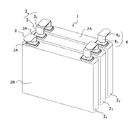
以下、図面を参照して本発明の最良の実施形態を説明する。但し、以下に示す実施形態は、本発明の技術思想を具体化するための電池の接続構造及び接続方法を例示するものであって、本発明をこの電池の接続構造及び接続方法に特定することを意図するものではなく、特許請求の範囲に含まれるその他の実施形態のものも等しく適応し得るものである。なお、図1は実施例1に係る接続構造が適用された電池モジュールの外観斜視図、図2は図1の電池モジュールを構成する1個の電池の外観斜視図、図3(a)はあて板の外観斜視図であり、図3(b)は抵抗溶接法によって実施例1の電池の接続構造を形成する際の拡大側面図である。更に、図4は実施例2に係る接続構造を示し、図4(a)は溶接前の縦断面図、図4(b)溶接後の縦断面図であり、また、図5は実施例2の接続構造の変形例における溶接前の縦断面図である。 Hereinafter, the best embodiment of the present invention will be described with reference to the drawings. However, the embodiment described below exemplifies a battery connection structure and a connection method for embodying the technical idea of the present invention, and the present invention is specified to this battery connection structure and connection method. And other embodiments within the scope of the claims are equally applicable. 1 is an external perspective view of a battery module to which the connection structure according to the first embodiment is applied, FIG. 2 is an external perspective view of one battery constituting the battery module of FIG. 1, and FIG. It is an external appearance perspective view of a board, FIG.3 (b) is an enlarged side view at the time of forming the connection structure of the battery of Example 1 by a resistance welding method. 4 shows the connection structure according to the second embodiment, FIG. 4 (a) is a longitudinal sectional view before welding, FIG. 4 (b) is a longitudinal sectional view after welding, and FIG. It is a longitudinal cross-sectional view before welding in the modification of this connection structure.
電池モジュール1は、図1に示すように、複数個、例えば3個のリチウムイオン電池(以下、電池という)21〜23でモジュール化されている。これらの電池のそれぞれは、その一つの電池2を図2に示すように、それぞれ金属製ケーシング2Bの上面2Aに板状の正極端子3及び負極端子4が突き出されている。そして、金属製ケーシング2B内には図示しない正極板、負極板、セパレータ及び電解液が収容されている。
Cell module 1, as shown in FIG. 1, a plurality, for example three lithium ion batteries are modularized in 2 1 to 2 3 (hereinafter, referred to as cells). As shown in FIG. 2, each of these batteries has a plate-like
正極板はアルミニウム又はアルミニウム合金箔からなる集電体の両面に例えばリチウム複合酸化物を含む正極活物質合剤が薄層状に塗布されており、このアルミニウム又はアルミニウム合金箔からなる集電体は同じくアルミニウム又はアルミニウム合金材からなる正極端子3に接続されている。同様に、負極板は銅又は銅合金箔からなる集電体の両面に例えば炭素材料を含む負極活物質合剤が薄層状に塗布されており、この銅又は銅合金箔からなる集電体は同じく銅又は銅合金材からなる負極端子4に接続されている。
In the positive electrode plate, a positive electrode active material mixture containing, for example, a lithium composite oxide is applied in a thin layer on both sides of a current collector made of aluminum or aluminum alloy foil, and the current collector made of aluminum or aluminum alloy foil is the same. It is connected to a
これらの、正極端子3及び負極端子4は、それぞれ所定幅長及び厚みを有し、両者とも実質的に同じ長さの平板状に形成されている。また、あて板5は、図3(a)に示すように、正極端子3及び負極端子4の折り曲げ部と実質的に同じ大きさ及び厚さを有する板材からなり、正極端子よりも融点が高い銅、銅合金、ニッケル及びステンレススチールから選択された1種が用いられる。ここでは、負極端子4と同じ銅又は銅合金材からなるものを使用した。
The
個々の電池は、以下の手順で接続される。先ず、3個の電池21〜23を併設した際に正極端子3の上に負極端子4が重なるように、正極端子3及び負極端子4を途中から互いに逆方向に折り曲げる。すなわち、図1に示すように、正極端子3は、垂直部31とこの垂直部から略90度に図面上右方向に折り曲げた折り曲げ部32とからなり、負極端子4も垂直部41とこの垂直部から図面上左方向に略90度に折り曲げた折り曲げ部42とからなり、正極端子3の垂直部31は負極端子4の垂直部41より僅かに高さが低くなっている。
Individual batteries are connected in the following procedure. First, the
次いで、3個の電池21〜23を隣接する電池間の相互に対向する端子の極性が異なるように配列し、隣接する電池の正極端子3の折り曲げ部32及び負極端子4の折り曲げ部42が重なるようにする。この状態では、正極端子3の垂直部31は負極端子4の垂直部41より僅かに高さが低くなっているため、必ず正極端子3が負極端子4の下に配置される。この状態で、正極端子3の折り曲げ部32の下側に図3(a)に示した形状のあて板5を当接させ、次いで、図3(b)に示したように、このあて板5の下面に電気溶接機の下側電極棒6Aを当接するとともに、負極端子4の折り曲げ部42の上部に上側電極棒6Bを当接する。
Then, three cells 2 1 arrayed to 2 3 to the polarity of the terminals facing each other between adjacent cells is different, bent portion of the
この状態の接続部C1の構成は、上側から上側電極棒6B−銅又は銅合金材からなる負極端子の折り曲げ部42−アルミニウム又はアルミニウム合金材からなる正極端子の折り曲げ部32−銅又は銅合金材からなるあて板5−下側電極棒6Aとなる。この状態で、図示しない電気溶接装置から下側電極棒6A及び上側電極棒6B間に所定の電流を流して抵抗溶接する。
Configuration of the connection portion C 1 in this state, the bent portion of the negative terminal from above consisting of the
そうすると、溶接時には、銅又は銅合金材からなる負極端子4の折り曲げ部42とあて板5との間にアルミニウム又はアルミニウム合金材からなる正極端子3の折り曲げ部32が挟み込まれた状態で溶接されるので、電極棒6Aないし6Bは正極端子3の折り曲げ部32とは直接接触していないため、電極棒6Aないし6Bへのアルミニウム又はアルミニウム合金の付着が防止できるとともに、アルミニウム又はアルミニウム合金が過溶融しても周囲へスパッタされることがなくなる。
Then, at the time of welding, the welding in a state where the bending
したがって、この接続部C1の構成により、正極端子3と負極端子4とが異種金属で形成されていても、正極端子3よりも融点が高い材料からなるあて板5を使用することにより、溶接強度が強くて信頼性が大きく、しかも、特殊な材料を使用しないですむため、低コストでリチウムイオン電池を直列接続することができる。なお、この接続構造C1では、正極端子3の垂直部31が負極端子4の垂直部41よりも僅かに高さが低くなるようにして、上方から負極端子4の折り曲げ部42−正極端子3の折り曲げ部32−あて板5の順番に配置されるようにしたが、これとは逆に、正極端子3の垂直部31を負極端子4の垂直部41より僅かに高さが高くなるようにして、上方から順番にあて板5−正極端子3の折り曲げ部32−負極端子4の折り曲げ部42の順番となるように配置してもよい。要は、負極端子4の折り曲げ部42とあて板5の間に正極端子3の折り曲げ部32が配置されていればよいわけである。
Therefore, even if the
次に、図4を参照して実施例2の接続構造C2を説明する。この実施例2の接続構造C2は、図3(b)に示した実施例1の接続構造C1とは正極端子3の折り曲げ部32、負極端子4の折り曲げ部42及びあて板5の一部形状が異なる他は実質的に同一構成であるので、共通の構成には同一の参照符号を付して説明を省略する。
Next, the connection structure C2 of Example 2 will be described with reference to FIG. The connection structure C 2 of the second embodiment is different from the connection structure C 1 of the first embodiment shown in FIG. 3B in that the
この実施例2の接続構造C2は、負極端子4の折り曲げ部42及びあて板5に溶接時に対向する位置にそれぞれ突出部4a、5aを設け、正極端子3の折り曲げ部32の溶接部周辺に溶融したアルミニウム又はアルミニウム合金が流れ込むことができる領域としてのスリット3a、3aを形成した構成を有している。この場合、図4(a)に示すように、負極端子4の折り曲げ部42の突出部4aは折り曲げ部42の略中央部の上面を窪ませて下面側が突出するように形成されており、また、あて板5の突出部5aは下面を窪ませて上面側が突出するように形成されている。
Connection structure C 2 of the second embodiment, each projecting
ここで、隣接する電池間の相互に対向する端子の極性が異なるように配列し、隣接する電池の正極端子3の折り曲げ部32及び負極端子4の折り曲げ部42が重なるようにするとともに、あて板5を正極端子3の折り曲げ部32の下側に配置すると、図4(a)に示したように、負極端子4の折り曲げ部42の突出部4aとあて板5の突出部5aは互いに対向配置されるとともに、負極端子4の折り曲げ部42の突出部4aが正極端子3の折り曲げ部32の上側に位置し、あて板5の突出部5aが正極端子3の折り曲げ部32の下側に位置するようになる。
Here, it arranged as the polarity of the terminals facing each other between adjacent cells is different, as well as to bent portion 4 2 of the bending
この状態で抵抗溶接を行うと、各突出部4a、5aに抵抗溶接の電流が集中するため、効率よく抵抗溶接が行われる。また、正極端子3の折り曲げ部32に設けたスリット3a、3a内に溶融したアルミニウム又はアルミニウム合金が流れ込むため、アルミニウムが過溶融しても周囲へスパッタされることがなくなるとともに、それぞれ銅又は銅合金材からなる負極端子4の折り曲げ部42とあて板5との間からアルミニウム又はアルミニウム合金がはみ出してくることがなくなる。
If resistance welding is performed in this state, the resistance welding current concentrates on the
なお、実施例2では、正極端子3の折り曲げ部31の溶接部周辺にスリット3a、3aを設けた例を示したが、図5に示すように、溝3a'、3a'を設けてもよい。このような溝3a'、3a'でもスリット3a、3aの場合と同様の作用効果が得られる。また、実施例2では、負極端子4の折り曲げ部42及びあて板5の両者に突出部を形成した例を示したが、どちらか一方にのみ突出部を設けても同様の作用効果が得られる。
In Example 2, the bending
以上、本発明を上記の実施形態で詳細に説明したが、本発明はこれに限定されず、本発明が属する技術分野において通常の知識を有する者であれば、本発明の思想及び精神を離れることなく修正又は変更できる。例えば、本実施の形態では、複数個のリチウムイオン電池の接続構造について説明したが、この接続構造はリチウムイオン電池に限らず、例えば、電気二重層キャパシタを接続する場合に採用してもよい。 Although the present invention has been described in detail in the above embodiment, the present invention is not limited to this, and the person who has ordinary knowledge in the technical field to which the present invention belongs will depart from the spirit and spirit of the present invention. Can be modified or changed without any change. For example, in the present embodiment, a connection structure of a plurality of lithium ion batteries has been described. However, this connection structure is not limited to a lithium ion battery, and may be employed when, for example, an electric double layer capacitor is connected.
1 電池モジュール
2、21〜23 リチウムイオン電池
2B 金属製ケーシング
3 正極端子
31 垂直部
32 折り曲げ部
3a スリット
3a' 溝
4 負極端子
4a 突出部
41 垂直部
42 折り曲げ部
5 あて板
5a 突出部
6A、6B 電極棒
1 battery module 2, 2 1 ~ 2
Claims (8)
前記直列接続箇所は、それぞれ前記他方側の電極端子が前記一方側の電極端子と前記第2金属より融点が高い金属材料からなるあて板との間に配置された状態で溶接接続されていることを特徴とする電池の接続構造。 In a battery connection structure in which a plurality of batteries having one electrode terminal made of a first metal having a high melting point and the other electrode terminal made of a second metal having a melting point lower than that of the first metal are connected in series,
Each of the series connection locations is weld-connected in such a state that the other electrode terminal is disposed between the one electrode terminal and an address plate made of a metal material having a melting point higher than that of the second metal. A battery connection structure.
前記直列接続箇所は、それぞれ前記他方側の電極端子の折り曲げ部が前記一方側の電極端子の折り曲げ部と前記あて板との間に配置された状態で溶接接続されていることを特徴とする請求項1に記載の電池の接続構造。 The electrode terminal on one side and the electrode terminal on the other side of the battery are each protruded from the one end surface of the battery by a predetermined length and are bent in opposite directions to each other,
The series connection location is welded in a state where the bent portion of the electrode terminal on the other side is disposed between the bent portion of the electrode terminal on the one side and the cover plate, respectively. Item 6. A battery connection structure according to Item 1.
前記直列接続箇所において、前記他方側の電極端子の両面にそれぞれ前記一方側の電極端子及び前記第2金属より融点が高い金属材料からなるあて板を当接させ、
次いで、前記一方側の電極端子、他方側の電極端子及びあて板を同時に抵抗溶接することを特徴とする電池の接続方法。 In a battery connection method of connecting a plurality of batteries having one electrode terminal made of a first metal having a high melting point and the other electrode terminal made of a second metal having a melting point lower than that of the first metal in series,
In the series connection place, contact surfaces made of a metal material having a melting point higher than those of the one side electrode terminal and the second metal, respectively, on both surfaces of the other side electrode terminal,
Next, the battery connecting method, wherein the electrode terminal on one side, the electrode terminal on the other side, and the cover plate are simultaneously resistance-welded.
前記直列接続箇所において、前記他方側の電極端子の折り曲げ部の両面にそれぞれ前記一方側の電極端子の折り曲げ部及び前記あて板を当接させ、
次いで、前記一方側の電極端子の折り曲げ部、他方側の電極端子の折り曲げ部及びあて板を同時に抵抗溶接することを特徴とする請求項4に記載の電池の接続方法。 Bending the one side electrode terminal and the other side electrode terminal protruding in a predetermined length from one end surface of the battery in opposite directions to form a bent portion;
In the series connection place, the bent portion of the electrode terminal on one side and the contact plate are brought into contact with both surfaces of the bent portion of the electrode terminal on the other side, respectively.
5. The battery connection method according to claim 4, wherein the bent portion of the electrode terminal on one side, the bent portion of the electrode terminal on the other side, and the cover plate are simultaneously subjected to resistance welding.
Priority Applications (1)
| Application Number | Priority Date | Filing Date | Title |
|---|---|---|---|
| JP2006305448A JP2008123800A (en) | 2006-11-10 | 2006-11-10 | Connection structure and connection method for battery |
Applications Claiming Priority (1)
| Application Number | Priority Date | Filing Date | Title |
|---|---|---|---|
| JP2006305448A JP2008123800A (en) | 2006-11-10 | 2006-11-10 | Connection structure and connection method for battery |
Publications (1)
| Publication Number | Publication Date |
|---|---|
| JP2008123800A true JP2008123800A (en) | 2008-05-29 |
Family
ID=39508342
Family Applications (1)
| Application Number | Title | Priority Date | Filing Date |
|---|---|---|---|
| JP2006305448A Pending JP2008123800A (en) | 2006-11-10 | 2006-11-10 | Connection structure and connection method for battery |
Country Status (1)
| Country | Link |
|---|---|
| JP (1) | JP2008123800A (en) |
Cited By (27)
| Publication number | Priority date | Publication date | Assignee | Title |
|---|---|---|---|---|
| JP2010086688A (en) * | 2008-09-30 | 2010-04-15 | Sanyo Electric Co Ltd | Sealed battery |
| WO2010066620A1 (en) * | 2008-12-08 | 2010-06-17 | Continental Automotive Gmbh | Energy store |
| JP2011014276A (en) * | 2009-06-30 | 2011-01-20 | Gs Yuasa Corp | Battery |
| US20110081568A1 (en) * | 2009-10-05 | 2011-04-07 | Sung-Bae Kim | Battery module |
| US8007935B2 (en) | 2006-10-30 | 2011-08-30 | Byd Co., Ltd. | Plate assembly, core and lithium ion battery |
| JP2011204439A (en) * | 2010-03-25 | 2011-10-13 | Furukawa Battery Co Ltd:The | Battery pack, resistance welding method, and method for manufacturing battery pack |
| CN102222786A (en) * | 2010-04-16 | 2011-10-19 | Sb锂摩托有限公司 | Battery module and vehicle |
| WO2011148641A1 (en) * | 2010-05-26 | 2011-12-01 | 住友重機械工業株式会社 | Shovel |
| US8092936B2 (en) | 2007-12-25 | 2012-01-10 | Byd Co. Ltd. | Electrochemical cell having a coiled core |
| CN102332611A (en) * | 2011-09-23 | 2012-01-25 | 深圳市格瑞普电池有限公司 | Lithium-ion battery pack and welding method for single cells in lithium-ion battery pack |
| US8178230B2 (en) | 2007-12-18 | 2012-05-15 | Byd Co., Ltd. | Battery pack |
| US8178225B2 (en) | 2007-11-29 | 2012-05-15 | Byd Co., Ltd. | Battery and preparation method thereof |
| US8193770B2 (en) | 2007-12-25 | 2012-06-05 | BYD Co. Ltd | Battery system for a vehicle having an over-current/over-temperature protective feature |
| US8276695B2 (en) | 2007-12-25 | 2012-10-02 | Byd Co. Ltd. | Battery electrode sheet |
| US8329333B2 (en) | 2008-12-11 | 2012-12-11 | Samsung Sdi Co., Ltd. | Battery module with plurality of batteries having bent terminal portions connected with fixing plate |
| US8420254B2 (en) | 2007-12-25 | 2013-04-16 | Byd Co. Ltd. | End cover assembly for an electrochemical cell |
| KR20130042430A (en) * | 2011-10-18 | 2013-04-26 | 에스케이이노베이션 주식회사 | Battery module and middle or large-sized battery module having battery module |
| US8460818B2 (en) | 2009-10-05 | 2013-06-11 | Samsung Sdi Co., Ltd. | Battery module |
| CN103464851A (en) * | 2012-06-06 | 2013-12-25 | 支红俊 | Series-parallel connection precise thermocompression bonding process for soft-packing cell lug of lithium battery pack |
| CN103733386A (en) * | 2011-08-31 | 2014-04-16 | 株式会社Lg化学 | Interconnect assembly and method for forming interconnect assembly in battery module |
| JP2014078366A (en) * | 2012-10-10 | 2014-05-01 | Auto Network Gijutsu Kenkyusho:Kk | Power storage module |
| KR20140102837A (en) * | 2013-02-15 | 2014-08-25 | 주식회사 엘지화학 | Method of stacking battery as bending electrode tabs |
| KR101727286B1 (en) * | 2015-08-03 | 2017-04-17 | 에스케이이노베이션 주식회사 | Battery module having weld |
| US9905892B2 (en) | 2015-02-09 | 2018-02-27 | Lg Chem, Ltd. | Battery module and method of coupling first and second electrical terminals of first and second battery cells to first and second voltage sense members of an interconnect assembly |
| JP2021150247A (en) * | 2020-03-23 | 2021-09-27 | 愛三工業株式会社 | Welding method and battery module manufacturing method |
| EP3840085A4 (en) * | 2018-08-13 | 2022-05-18 | Vehicle Energy Japan Inc. | BATTERY MODULE |
| CN115708252A (en) * | 2021-08-18 | 2023-02-21 | 丰田自动车株式会社 | Battery pack and method for manufacturing same |
-
2006
- 2006-11-10 JP JP2006305448A patent/JP2008123800A/en active Pending
Cited By (51)
| Publication number | Priority date | Publication date | Assignee | Title |
|---|---|---|---|---|
| US8007935B2 (en) | 2006-10-30 | 2011-08-30 | Byd Co., Ltd. | Plate assembly, core and lithium ion battery |
| US8178225B2 (en) | 2007-11-29 | 2012-05-15 | Byd Co., Ltd. | Battery and preparation method thereof |
| US8178230B2 (en) | 2007-12-18 | 2012-05-15 | Byd Co., Ltd. | Battery pack |
| US8420254B2 (en) | 2007-12-25 | 2013-04-16 | Byd Co. Ltd. | End cover assembly for an electrochemical cell |
| US10147930B2 (en) | 2007-12-25 | 2018-12-04 | Shenzhen Byd Auto R&D Company Limited | Construction of electrochemical storage cell with conductive block |
| US8865335B2 (en) | 2007-12-25 | 2014-10-21 | Byd Co. Ltd. | Electrochemical storage cell |
| US9741996B2 (en) | 2007-12-25 | 2017-08-22 | Byd Co. Ltd. | Construction of electrochemical storage cell |
| US8404379B2 (en) | 2007-12-25 | 2013-03-26 | Byd Co., Ltd. | Vehicle with a battery system |
| US10381632B2 (en) | 2007-12-25 | 2019-08-13 | Shenzhen Byd Auto R&D Company Limited | Construction of electrochemical storage cell with conductive bridge |
| US8092936B2 (en) | 2007-12-25 | 2012-01-10 | Byd Co. Ltd. | Electrochemical cell having a coiled core |
| US8383257B2 (en) | 2007-12-25 | 2013-02-26 | Byd Co. Ltd. | Electrochemical storage cell with blow out vents |
| US8399116B2 (en) | 2007-12-25 | 2013-03-19 | Byd Co. Ltd. | Optimized dimensional relationships for an electrochemical cell having a coiled core |
| US8276695B2 (en) | 2007-12-25 | 2012-10-02 | Byd Co. Ltd. | Battery electrode sheet |
| US8193770B2 (en) | 2007-12-25 | 2012-06-05 | BYD Co. Ltd | Battery system for a vehicle having an over-current/over-temperature protective feature |
| US8202644B2 (en) | 2007-12-25 | 2012-06-19 | Byd Co. Ltd. | Protection cover for an end cap assembly of a battery cell |
| JP2010086688A (en) * | 2008-09-30 | 2010-04-15 | Sanyo Electric Co Ltd | Sealed battery |
| WO2010066620A1 (en) * | 2008-12-08 | 2010-06-17 | Continental Automotive Gmbh | Energy store |
| US8329333B2 (en) | 2008-12-11 | 2012-12-11 | Samsung Sdi Co., Ltd. | Battery module with plurality of batteries having bent terminal portions connected with fixing plate |
| US8822061B2 (en) | 2008-12-11 | 2014-09-02 | Samsung Sdi Co., Ltd. | Battery module with plurality of batteries having bent terminal portions connected with fixing plate |
| JP2011014276A (en) * | 2009-06-30 | 2011-01-20 | Gs Yuasa Corp | Battery |
| CN102034952A (en) * | 2009-10-05 | 2011-04-27 | Sb锂摩托有限公司 | Battery module and method for connecting terminals of rechargeable batteries of battery module |
| US9196890B2 (en) | 2009-10-05 | 2015-11-24 | Samsung Sdi Co., Ltd. | Battery module with welded portion between terminals |
| US8460818B2 (en) | 2009-10-05 | 2013-06-11 | Samsung Sdi Co., Ltd. | Battery module |
| US20110081568A1 (en) * | 2009-10-05 | 2011-04-07 | Sung-Bae Kim | Battery module |
| JP2011204439A (en) * | 2010-03-25 | 2011-10-13 | Furukawa Battery Co Ltd:The | Battery pack, resistance welding method, and method for manufacturing battery pack |
| CN102222786A (en) * | 2010-04-16 | 2011-10-19 | Sb锂摩托有限公司 | Battery module and vehicle |
| CN102222786B (en) * | 2010-04-16 | 2014-08-20 | 三星Sdi株式会社 | Battery module and vehicle |
| US8628875B2 (en) | 2010-04-16 | 2014-01-14 | Samsung Sdi Co., Ltd. | Battery module with multi-level connector |
| JPWO2011148641A1 (en) * | 2010-05-26 | 2013-07-25 | 住友重機械工業株式会社 | Excavator |
| WO2011148641A1 (en) * | 2010-05-26 | 2011-12-01 | 住友重機械工業株式会社 | Shovel |
| US20130065103A1 (en) * | 2010-05-26 | 2013-03-14 | Sumitomo Heavy Industries, Ltd. | Shovel |
| US9318768B2 (en) | 2010-05-26 | 2016-04-19 | Sumitomo Heavy Industries, Ltd. | Shovel |
| US9882192B2 (en) | 2011-08-31 | 2018-01-30 | Lg Chem, Ltd. | Interconnection assemblies and methods for forming the interconnection assemblies in a battery module |
| CN103733386B (en) * | 2011-08-31 | 2016-08-17 | 株式会社Lg化学 | Interconnect assembly and method for forming interconnect assembly in battery module |
| JP2014526132A (en) * | 2011-08-31 | 2014-10-02 | エルジー・ケム・リミテッド | Interconnect assembly and method of forming an interconnect assembly in a battery module |
| CN103733386A (en) * | 2011-08-31 | 2014-04-16 | 株式会社Lg化学 | Interconnect assembly and method for forming interconnect assembly in battery module |
| CN102332611A (en) * | 2011-09-23 | 2012-01-25 | 深圳市格瑞普电池有限公司 | Lithium-ion battery pack and welding method for single cells in lithium-ion battery pack |
| KR20130042430A (en) * | 2011-10-18 | 2013-04-26 | 에스케이이노베이션 주식회사 | Battery module and middle or large-sized battery module having battery module |
| KR101944826B1 (en) | 2011-10-18 | 2019-04-17 | 에스케이이노베이션 주식회사 | Battery Module and Middle or Large-sized Battery Module having Battery Module |
| CN103464851A (en) * | 2012-06-06 | 2013-12-25 | 支红俊 | Series-parallel connection precise thermocompression bonding process for soft-packing cell lug of lithium battery pack |
| JP2014078366A (en) * | 2012-10-10 | 2014-05-01 | Auto Network Gijutsu Kenkyusho:Kk | Power storage module |
| KR101675617B1 (en) | 2013-02-15 | 2016-11-11 | 주식회사 엘지화학 | Method of stacking battery as bending electrode tabs |
| KR20140102837A (en) * | 2013-02-15 | 2014-08-25 | 주식회사 엘지화학 | Method of stacking battery as bending electrode tabs |
| US9905892B2 (en) | 2015-02-09 | 2018-02-27 | Lg Chem, Ltd. | Battery module and method of coupling first and second electrical terminals of first and second battery cells to first and second voltage sense members of an interconnect assembly |
| KR101727286B1 (en) * | 2015-08-03 | 2017-04-17 | 에스케이이노베이션 주식회사 | Battery module having weld |
| EP3840085A4 (en) * | 2018-08-13 | 2022-05-18 | Vehicle Energy Japan Inc. | BATTERY MODULE |
| US12191527B2 (en) | 2018-08-13 | 2025-01-07 | Vehicle Energy Japan Inc. | Battery module |
| JP2021150247A (en) * | 2020-03-23 | 2021-09-27 | 愛三工業株式会社 | Welding method and battery module manufacturing method |
| JP7348119B2 (en) | 2020-03-23 | 2023-09-20 | 愛三工業株式会社 | Welding method and battery module manufacturing method |
| CN115708252A (en) * | 2021-08-18 | 2023-02-21 | 丰田自动车株式会社 | Battery pack and method for manufacturing same |
| CN115708252B (en) * | 2021-08-18 | 2025-10-10 | 丰田自动车株式会社 | Battery pack and manufacturing method thereof |
Similar Documents
| Publication | Publication Date | Title |
|---|---|---|
| JP2008123800A (en) | Connection structure and connection method for battery | |
| EP3159953B1 (en) | Battery pack tab welding method | |
| EP3258520B1 (en) | Lithium secondary battery having improved safety by using bimetal tab | |
| JP2023082048A5 (en) | ||
| WO2013176914A1 (en) | Bimetal buss bar assembly | |
| JP5231235B2 (en) | Secondary battery for medium and large battery modules | |
| CN103563128A (en) | Cell connector | |
| WO2013065523A1 (en) | Cell assembly, and rectangular secondary cell for use in cell assembly | |
| US10381677B2 (en) | Secondary battery | |
| JP2006261083A (en) | Battery connection device | |
| CN108428818B (en) | Power battery top cover structure, power battery and battery module | |
| JP5207283B2 (en) | Battery pack and battery pack | |
| JP5558878B2 (en) | Assembled battery, resistance welding method, and assembled battery manufacturing method | |
| JP2000164195A (en) | Non-aqueous electrolyte secondary battery | |
| JP2005116434A (en) | Battery electrode welding method and battery pack | |
| JP7288456B2 (en) | secondary battery | |
| JP2004127554A (en) | Connection lead plate and battery with lead plate | |
| JP5622676B2 (en) | Battery and tab connection method and tab | |
| JP2016092005A (en) | Power storage device and manufacturing method of power storage device | |
| CN111987280B (en) | Battery pack | |
| KR101124964B1 (en) | Method for connecting between cathod lead or anode lead of secondary battery and external element | |
| JP6442975B2 (en) | Terminal-to-terminal connector and power storage device | |
| US10811664B2 (en) | Battery module | |
| WO2012171071A1 (en) | Adaptor interface | |
| CN105845881A (en) | Connection structure for power module of power battery |