JP2008119214A - Magnetic resonance imaging device and rf irradiation coil - Google Patents
Magnetic resonance imaging device and rf irradiation coil Download PDFInfo
- Publication number
- JP2008119214A JP2008119214A JP2006305841A JP2006305841A JP2008119214A JP 2008119214 A JP2008119214 A JP 2008119214A JP 2006305841 A JP2006305841 A JP 2006305841A JP 2006305841 A JP2006305841 A JP 2006305841A JP 2008119214 A JP2008119214 A JP 2008119214A
- Authority
- JP
- Japan
- Prior art keywords
- magnetic field
- coil
- irradiation
- gradient magnetic
- resonance imaging
- Prior art date
- Legal status (The legal status is an assumption and is not a legal conclusion. Google has not performed a legal analysis and makes no representation as to the accuracy of the status listed.)
- Granted
Links
Images


Landscapes
- Magnetic Resonance Imaging Apparatus (AREA)
Abstract
Description
本発明は、磁気共鳴イメージング(以下、MRIという)装置に関し、特に、傾斜磁場コイルの効率を向上させたMRI装置における、RF照射コイルの構造に関する。 The present invention relates to a magnetic resonance imaging (hereinafter referred to as MRI) apparatus, and more particularly to a structure of an RF irradiation coil in an MRI apparatus in which the efficiency of a gradient magnetic field coil is improved.
MRI装置は、磁場中に置かれた被検体の核磁気共鳴(以下、NMRという)現象から得られる信号(NMR信号)を計測し演算処理することにより、被検体中の各スピンの密度分布、緩和時間分布等を断層像として画像表示するものであり、人体を被検体として各種の診断等に使用されている。 The MRI apparatus measures and computes a signal (NMR signal) obtained from a nuclear magnetic resonance (hereinafter referred to as NMR) phenomenon of a subject placed in a magnetic field, thereby calculating the density distribution of each spin in the subject, The relaxation time distribution or the like is displayed as a tomographic image, and is used for various diagnoses or the like with the human body as the subject.
MRI装置では、静磁場発生源が形成する空間的、時間的に一様な強度と方向を持った静磁場空間中に被検体を置き、高周波コイル(RF照射コイル)によりパルス状に電磁波を被検体に照射し、それによって発生するNMR信号を高周波コイル(RF受信コイル)により受信する。このとき、3軸方向に直交する傾斜磁場コイルが生成する傾斜磁場により、NMR信号に位置情報が与えられる。 In an MRI apparatus, a subject is placed in a static magnetic field space having a uniform intensity and direction in time and formed by a static magnetic field generation source, and electromagnetic waves are pulsated by a high frequency coil (RF irradiation coil). The specimen is irradiated and the NMR signal generated thereby is received by a high frequency coil (RF receiving coil). At this time, position information is given to the NMR signal by the gradient magnetic field generated by the gradient magnetic field coils orthogonal to the three axial directions.
上述の静磁場発生源と、RF照射コイルと、傾斜磁場コイルとは、被験体の入る空間(撮像空間)から見ると、内側から、RF照射コイル、傾斜磁場コイル、静磁場発生源の順に、層構造を成して配置される。また、RF照射コイルと被験体の入る空間の間には、カバーが、RF照射コイルと、傾斜磁場コイルとの間には、RFシールドが配置される。静磁場方向が水平方向である水平磁場機の場合、これらはそれぞれ概ね円筒形状で、静磁場に平行な方向をZ軸方向とすると、Z軸を中心とした同心円状に配置される。 The static magnetic field generation source, the RF irradiation coil, and the gradient magnetic field coil are viewed in the order of the RF irradiation coil, the gradient magnetic field coil, and the static magnetic field generation source from the inside when viewed from the space (imaging space) where the subject enters. Arranged in a layered structure. Further, a cover is disposed between the RF irradiation coil and the space where the subject enters, and an RF shield is disposed between the RF irradiation coil and the gradient magnetic field coil. In the case of horizontal magnetic field machines in which the static magnetic field direction is the horizontal direction, these are each generally cylindrical, and are arranged concentrically around the Z axis, where the direction parallel to the static magnetic field is the Z axis direction.
MRI装置では、カバーから傾斜磁場コイルまでの厚さはできるだけ薄い方がよい。この厚さを薄くすることにより、外側の静磁場発生源と被検体との距離が短くなり磁場発生効率が向上するためである。または、同じ静磁場発生源により、被検体の入る空間を広く構成できる。一方で、MRI装置では、各層間の間隔等はできるだけ広い方がよい。間隔を広くすることにより、傾斜磁場コイル、RF照射コイルの磁場発生効率が上がり、傾斜磁場強度の増大もしくは傾斜磁場の立ち上がり速度の高速化を図ることが出来るためである。従って、MRI装置には、カバーから傾斜磁場コイルまでの厚さは薄くし、かつ、それぞれの層間の間隔は広げるという、相反する要求がある。 In the MRI apparatus, the thickness from the cover to the gradient coil is preferably as thin as possible. This is because by reducing the thickness, the distance between the outside static magnetic field generation source and the subject is shortened, and the magnetic field generation efficiency is improved. Alternatively, the space where the subject enters can be configured widely by the same static magnetic field generation source. On the other hand, in the MRI apparatus, it is preferable that the distance between the layers is as wide as possible. This is because by increasing the interval, the magnetic field generation efficiency of the gradient magnetic field coil and the RF irradiation coil is increased, and the gradient magnetic field strength can be increased or the rising speed of the gradient magnetic field can be increased. Therefore, the MRI apparatus has conflicting demands that the thickness from the cover to the gradient magnetic field coil is thin and the distance between each layer is widened.
近年、RF照射コイルの存在しない部分において、傾斜磁場コイルを円筒の半径方向内側にせり出させる構造が提案されている(例えば、特許文献1参照)。この構造により、カバーから傾斜磁場コイルまでの厚さは同じであっても、傾斜磁場コイルをせり出させた部分では、各コイル間の間隔を広げることができ、傾斜磁場コイルの効率を向上させることができる。 In recent years, there has been proposed a structure in which the gradient magnetic field coil protrudes inward in the radial direction of the cylinder in a portion where the RF irradiation coil does not exist (see, for example, Patent Document 1). With this structure, even if the thickness from the cover to the gradient coil is the same, the space between the coils can be increased in the portion where the gradient coil is protruded, and the efficiency of the gradient coil is improved. be able to.
水平磁場機において、特許文献1に記載の構成によって傾斜磁場コイルを形成した場合、上述の利点がある。しかし、RF照射コイルの外径は傾斜磁場コイルの最も小さい内径よりも大きくなるので、円筒型を基本とした水平磁場機では従来の様に完成した傾斜磁場コイルの内側にそのままRF照射コイルを挿入することは出来ない。また、RF照射コイルは、実装時にチューニングを行うため、取り外す必要がある。しかし、上述の構成では、容易に取り外すことが出来ない。すなわち、特許文献1では、このような場合のRF照射コイルの実装形態についての検討はなされていない。
In the horizontal magnetic field machine, when the gradient magnetic field coil is formed by the configuration described in
本発明は、上記事情に鑑みてなされたもので、傾斜磁場コイルの最も小さい内径よりもRF照射コイルの外径が大きいMRI装置において、RF照射コイルの現実的な実装形態を提供することを目的とする。 The present invention has been made in view of the above circumstances, and an object of the present invention is to provide a realistic mounting form of an RF irradiation coil in an MRI apparatus in which the outer diameter of the RF irradiation coil is larger than the smallest inner diameter of the gradient magnetic field coil. And
上記目的を達成するために、本発明のRFコイルは、実装時にその外径が傾斜磁場コイルの最小内径より小さくなるよう変形可能とする。 In order to achieve the above object, the RF coil of the present invention can be deformed so that its outer diameter becomes smaller than the minimum inner diameter of the gradient coil when mounted.
具体的には、傾斜磁場を発生する中空の回転体である傾斜磁場発生手段と、RF磁場を発生する中空の回転体であるRF照射手段と、を備える水平磁場方式の磁気共鳴イメージング装置において、前記傾斜磁場発生手段は、前記RF照射手段の最大外径より小さい内径を有する部分を備え、前記RF照射手段は、当該RF照射手段の最も大きい断面が前記傾斜磁場発生手段の最も小さい断面に含まれるよう可逆的に変形可能であることを特徴とする磁気共鳴イメージング装置を提供する。 Specifically, in a horizontal magnetic field magnetic resonance imaging apparatus comprising a gradient magnetic field generating means that is a hollow rotating body that generates a gradient magnetic field, and an RF irradiation means that is a hollow rotating body that generates an RF magnetic field. The gradient magnetic field generation means includes a portion having an inner diameter smaller than the maximum outer diameter of the RF irradiation means, and the RF irradiation means includes the largest cross section of the RF irradiation means included in the smallest cross section of the gradient magnetic field generation means. A magnetic resonance imaging apparatus is provided that is reversibly deformable.
また、円筒形状の静磁場発生手段と、中空形状の傾斜磁場発生手段と、中空形状のRF照射手段と、を備える磁気共鳴イメージング装置において、前記傾斜磁場発生手段は、第1の内径と該第1の内径より小さい第2の内径とを有し、前記RF照射手段は、前記第1の内径に対応した第1の形態と前記第2の内径に対応した第2の形態とに可逆的に変更可能に形成されているとともに、前記傾斜磁場発生手段の第1の内径の近傍では、前記第1の形態を有して配設されることを特徴とする磁気共鳴イメージング装置を提供する。 Further, in the magnetic resonance imaging apparatus comprising a cylindrical static magnetic field generating means, a hollow gradient magnetic field generating means, and a hollow RF irradiation means, the gradient magnetic field generating means includes a first inner diameter and the first inner diameter. The RF irradiating means is reversibly reversible between a first form corresponding to the first inner diameter and a second form corresponding to the second inner diameter. Provided is a magnetic resonance imaging apparatus which is formed so as to be changeable and has the first form in the vicinity of a first inner diameter of the gradient magnetic field generating means.
本発明によれば、傾斜磁場コイルの最も小さい内径よりもRF照射コイルの外径が大きいMRI装置において、RFコイルの現実的な実装形態を提供することができる。 According to the present invention, in an MRI apparatus in which the outer diameter of the RF irradiation coil is larger than the smallest inner diameter of the gradient magnetic field coil, a realistic mounting form of the RF coil can be provided.
以下、添付図面に従って本発明のMRI装置の好ましい実施形態について詳説する。なお、本発明は、静磁場方向が水平方向である水平磁場機に適用される。 Hereinafter, preferred embodiments of the MRI apparatus of the present invention will be described in detail with reference to the accompanying drawings. In addition, this invention is applied to the horizontal magnetic field machine whose static magnetic field direction is a horizontal direction.
<第一の実施形態>
本発明を適用する第一の実施形態のMRI装置の一例の全体概要を説明する。図1は、本実施形態のMRI装置の全体構成を示す機能ブロック図である。
<First embodiment>
An overall outline of an example of the MRI apparatus according to the first embodiment to which the present invention is applied will be described. FIG. 1 is a functional block diagram showing the overall configuration of the MRI apparatus of this embodiment.
本実施形態のMRI装置は、NMR現象を利用して被検体の断層画像を得るもので、静磁場発生系2と、傾斜磁場発生系3と、送信系5と、受信系6と、信号処理系7と、シーケンサ4と、中央処理装置(CPU)8と、操作部25と、を備える。
The MRI apparatus of the present embodiment obtains a tomographic image of a subject using an NMR phenomenon, and includes a static magnetic
静磁場発生系2は、被検体1の体軸方向に均一な静磁場を発生させる。静磁場発生系2は、被検体1の周りに配置された、例えば、永久磁石方式、常電導方式あるいは超電導方式の静磁場発生源により実現される。
The static magnetic
傾斜磁場発生系3は、受信した信号の位置を特定するための傾斜磁場を発生させる。本実施形態の傾斜磁場発生系3は、MRI装置の座標系(静止座標系)であるX,Y,Zの3軸方向に傾斜磁場Gx,Gy,Gzをそれぞれ発生する傾斜磁場コイル200と、それらを駆動する傾斜磁場電源10とを備える。傾斜磁場電源10は、後述するシーケンサ4からの命令に従って、傾斜磁場コイル200を駆動し、所定方向の傾斜磁場を発生させる。各傾斜磁場Gx,Gy,Gzは、それぞれ、スライス面(撮影断面)の選択、位相エンコードおよび周波数エンコード(読み取り)に用いられ、NMR信号に位置情報を与える。
The gradient magnetic
送信系5は、被検体1の生体組織を構成する原子の原子核スピンに核磁気共鳴を起こさせるために、被検体1に照射するRFパルスを発生させる。送信系5は、高周波発振器11と変調器12と高周波増幅器13と送信側の高周波コイル(RF照射コイル)400とを備える。高周波発振器11から出力された高周波パルスは、シーケンサ4からの指令によるタイミングで変調器12により振幅変調され、高周波増幅器13で増幅され、被検体1に近接して配置されたRF照射コイル400からRFパルスとして被検体1に照射される。
The
受信系6は、被検体1の生体組織を構成する原子核スピンの核磁気共鳴により放出されるNMR信号を検出する。受信系6は、受信側の高周波コイル(RF受信コイル)14と信号増幅器15と直交位相検波器16とA/D変換器17とを備える。RF照射コイル400から照射されたRFパルスによって誘起された被検体1からのNMR信号は、被検体1に近接して配置された高周波コイル14で検出され、信号増幅器15で増幅され、シーケンサ4からの指令によるタイミングで直交位相検波器16により直交する二系統の信号に分割され、それぞれA/D変換器17でディジタル量に変換されて、信号処理系7に送られる。なお、RF照射コイル400は、RF受信コイル14を兼ねる構成であってもよい。
The receiving system 6 detects an NMR signal emitted by nuclear magnetic resonance of nuclear spins constituting the biological tissue of the
シーケンサ4は、CPU8から受け取るパルスシーケンス情報に従って、傾斜磁場発生系3、送信系5、および、受信系6を制御し、所定のパルスシーケンスを実行させ、スピンエコー法、グラジエントエコー法等の種々の撮像方法を実現する。パルスシーケンス情報は、高周波パルス(RF照射パルス)および傾斜磁場パルスの磁場強度、磁場パルス照射、および、NMR信号検出のタイミング、繰り返し時間などの情報であり操作部25を介してユーザが設定した条件または予め定められた条件が用いられる。
The sequencer 4 controls the gradient magnetic
信号処理系7は、各種データ処理と処理結果の表示および保存等を行う。信号処理系7は、光ディスク19、磁気ディスク18、ROM21、RAM22等の記憶装置と、CRT等からなるディスプレイ20とを備える。信号処理系7は、CPU8の制御に従って、受信系6から受け取ったデータに信号処理、画像再構成等の処理を実行し、得られた被検体1の断層画像をディスプレイ20に表示するとともに、外部記憶装置の磁気ディスク18等に記録する。
The signal processing system 7 performs various data processing and display and storage of processing results. The signal processing system 7 includes a storage device such as an
操作部25は、MRI装置の各種制御情報や信号処理系7で行う処理の制御情報の入力のインタフェースである。操作部25は、トラックボール又はマウス23、及び、キーボード24を備える。操作部25は、ディスプレイ20に近接して配置され、操作者がディスプレイ20を見ながら操作部25を通してインタラクティブにMRl装置の各種処理を制御可能なように構成されている。
The
本実施形態のMRI装置の構造を説明する。図2は、本実施形態の水平磁場方式のMRI装置のZ軸に平行な方向の断面図である。本実施形態のMRI装置は、従来のMRI装置同様、静磁場発生源100、傾斜磁場コイル200、RFシールド300、RF照射コイル400、カバー500を備える。
The structure of the MRI apparatus of this embodiment will be described. FIG. 2 is a cross-sectional view in the direction parallel to the Z axis of the horizontal magnetic field MRI apparatus of the present embodiment. The MRI apparatus of this embodiment includes a static magnetic
これらは、従来例同様、それぞれ、概ね円筒形状を有し、被検体1の入る空間(撮像空間)から見ると、内側から、カバー500、RF照射コイル400、RFシールド300、傾斜磁場コイル200、静磁場発生源100の順に、Z軸を中心軸とした概ね同心円状に配置される。
As in the conventional example, each of these has a substantially cylindrical shape, and when viewed from the space (imaging space) into which the
静磁場発生源100は、静磁場発生系2を実現するもので、超伝導磁石、永久磁石などが用いられる。カバー500は、内部の電気部品と被験体との間の電気的絶縁および保護の役目をし、数mmの厚さの樹脂材料で構成される。また、RFシールド300は、RF照射コイル400の外側に、RF照射コイル400から一定の距離を置いて配置され、a)傾斜磁場コイル200から放出される傾斜磁場電源のノイズを低減する、b)傾斜磁場コイル200とRF照射コイル400との電磁結合を遮蔽して誘導損失を減らすことによりRF照射コイル400のQ(Quality factor)を高くする、という2つの役割を果たす。RFシールドは、非磁性金属箔や網を適宜積層して構成し、樹脂製支持部材に貼り付ける、または、後述の傾斜磁場コイル200の表面に貼り付けることにより配置する。なお、RFシールド300とRF照射コイル400との距離は、典型的には10mmから40mm必要である。近接させると、a)高周波渦電流が増えて磁場を打ち消すため、磁場の発生効率が悪くなる、b)RF照射コイル400近傍での磁場分布が急激に変化するため、撮影領域におけるRF強度の不均一性が大きくなる、という問題が生じるため、この間隔を狭くすることは難しい。
The static magnetic
傾斜磁場コイル200は、メインコイル、シールドコイルからなるASGC(Active Shielded Gradient Coil)が用いられる。メインコイルとシールドコイルとは、互いに逆向きの磁場を発生させる。また、傾斜磁場コイル200は、RF照射コイル400の、撮影空間に対してZ軸方向両外側に、中央部分の傾斜磁場コイル200の内半径(以下、Rとする。)より小さい内半径(以下、Rmin)を有する部分を備える。以下、傾斜磁場コイル200の内半径Rの部分を、凹部210、内半径Rminの部分を、凸部220と呼ぶ。なお、内半径Rminは、RF照射コイル400の外半径(以下、Rrfとする。)より小さいものとする。RF照射コイル400は、傾斜磁場コイル200の凹部210に嵌め込まれる。
As the gradient
次に、本実施形態のRF照射コイル400の形態について図3および図4を用いて説明する。本実施形態のRF照射コイル400は、その一部を柔軟な導体で構成し、折り畳むことにより配設時の形状に可逆的に変形可能な構造とする。折り畳んで傾斜磁場コイル200の凸部220を通過させて凹部210に挿入した後、凹部210内で拡げて実装する。
Next, the form of the
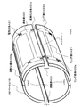
図3は、本実施形態のRF照射コイル400の概観図である。本図に示すように、本実施形態のRF照射コイル400は、基本的にはいわゆる従来のバードケージ型のコイルであり、中空の円筒形状のRFベース410と、RFベース410上の導体部420とを備える。
FIG. 3 is an overview of the
導体部420は、Z軸方向に伸びるラング導体421と、ラング導体421の両端部の円環状のリング導体422a、422bと、リング導体422a、422b上のコンデンサ等の電気部品423とを備える。ラング導体421の本数は問わない。例えば、16本、24本などである。導体部420の形状(導体パターン)は、例えば、10mmから30mmの幅の銅箔(銅条)を折り曲げ、接続することで得られる。もしくは、銅箔を貼り付けた基板から、不要な部分をエッチングで除去することで得られる。得られた導体パターンには、コンデンサ、ダイオード等の電気部品が取り付けられる。 The conductor 420 includes a rung conductor 421 extending in the Z-axis direction, annular ring conductors 422a and 422b at both ends of the rung conductor 421, and electrical components 423 such as capacitors on the ring conductors 422a and 422b. The number of rung conductors 421 does not matter. For example, 16 or 24. The shape (conductor pattern) of the conductor 420 is obtained by bending and connecting a copper foil (copper strip) having a width of 10 mm to 30 mm, for example. Alternatively, it can be obtained by removing unnecessary portions from the substrate to which the copper foil is attached by etching. Electrical components such as capacitors and diodes are attached to the obtained conductor pattern.
RFベース410は、巻き型にグラスファイバーのロービング(紐)を巻きつけ、樹脂を染み込ませて固める。もしくは、ガラスクロスにエポキシ樹脂を染み込ませ、半固化した状態のものを型に巻きつけて、プレスして固める。その後、規定の寸法になる様に削り、必要な穴を空けてRF照射コイル400のベースとする。このRFベース410は、前述のカバー500を兼ねる構造になっていてもよい。
The RF base 410 is made by winding glass fiber rovings (strings) around a winding mold, soaking the resin, and hardening. Alternatively, a glass cloth is impregnated with an epoxy resin, and a semi-solidified state is wound around a mold and pressed to be hardened. Then, it cuts so that it may become a regular dimension, a required hole is made, and it is set as the base of
また、本実施形態のRF照射コイル400は、さらに、Z軸方向に円筒の端から端まで伸びる折り曲げ可能な折曲部430を少なくとも4箇所備える。折曲部430は、ラング導体421および電気部品423を避けて設けられる。また、折曲部430において、リング導体422a、422bは、それぞれ、柔軟な導体424a、424bで構成され、RFベース410は、円筒の側面Z軸方向全長にわたるスリット411を有する。なお、柔軟な導体424a、424bの長さは、スリット411の幅以上とする。
Further, the
すなわち、本実施形態のRF照射コイル400は、従来のバードケージ型のRF照射コイルを周方向についてZ軸に沿って分割して得られる複数の円弧状の部分円筒からなる。そして、それぞれの部分円筒のリング導体422a、422bが、所定長の柔軟な導体424a、424bで接続されている。図3は、その円弧の中心角がそれぞれおよそ90度をなす部分円筒に4分割されている例である。
That is, the
柔軟な導体424a、424bに用いられる素材は、ポリイミドフイルムに銅箔を貼り付けたものに対してエッチングすることで得られるフレキシブル基板、銅板そのもの、銅線を平たく編んだ銅網線、細い導体を平面状に束ねたフラットケーブル等である。また、幅の広い導体を柔軟な導体424a、424bとして用いると、傾斜磁場により渦電流が発生し、傾斜磁場と静磁場との相互作用で振動、騒音が発生し、導体に曲げ疲労が発生する。このため、柔軟な導体424a、424bの導体幅は、傾斜磁場による渦電流の発生を抑制可能な範囲とする。例えば、数センチ程度がよい。 The materials used for the flexible conductors 424a and 424b are a flexible substrate obtained by etching a copper film on a polyimide film, a copper plate itself, a copper mesh wire obtained by flattening a copper wire, and a thin conductor. A flat cable bundled in a flat shape. When a wide conductor is used as the flexible conductors 424a and 424b, an eddy current is generated by the gradient magnetic field, vibration and noise are generated by the interaction between the gradient magnetic field and the static magnetic field, and bending fatigue occurs in the conductor. . For this reason, the conductor widths of the flexible conductors 424a and 424b are set in a range in which generation of eddy current due to the gradient magnetic field can be suppressed. For example, about several centimeters is good.
図4は、本実施形態のRF照射コイル400のZ軸に垂直な方向の断面図であり、実装時の様子を説明するための図である。図4(a)は、RF照射コイル400を折り畳んだ時の状態を説明するための図であり、図4(b)は、RF照射コイル400を展開して配設した時の状態を説明するための図である。本実施形態のRF照射コイル400は、上記の構造を有するため、図4(a)に示すように折曲部430において折り曲げることにより、折り畳むことが可能である。本実施形態では、RF照射コイル400を、折り畳んだ状態で傾斜磁場コイル200の凸部220を通し、凹部210に挿入してから図4(b)に示すように展開する。展開後、非磁性体好ましくは非導体のねじ、リベット等の固定ねじ440によりRFベース410を傾斜磁場コイル200側に設けた支持ボス230に固定し、配設する。
FIG. 4 is a cross-sectional view in the direction perpendicular to the Z-axis of the
固定時の様子を図5を用いて説明する。図5は、本実施形態のMRI装置のRF照射コイル400、RFシールド300、傾斜磁場コイル200部分の、Z軸に平行な方向の断面図である。傾斜磁場コイル200の内側(撮像空間側)にはRFシールド300が貼り付けられるとともに、支持ボス230が設けられる。支持ボス230には、RF照射コイル400が、固定ねじ440により固定される。
The state at the time of fixation is demonstrated using FIG. FIG. 5 is a cross-sectional view of the
本実施形態では、展開時のRF照射コイル400の外半径Rrfは、傾斜磁場コイル200の凸部220の内半径Rminより大きい。RF照射コイル400は、図4(a)に示すように折り畳むことにより、径方向の最大長hを展開時のRF照射コイル400の外半径Rrfより小さくすることができる。この最大長hが傾斜磁場コイル200の凸部220の内半径Rminより小さければ、RF照射コイル400の最も大きい断面が、凸部220の断面に含まれ、凸部220を通過させて凹部210へ挿入することが可能となる。従って、RF照射コイル400の折曲部430の数、位置は、上述のように折り畳んだ際の最大長hが、傾斜磁場コイル200の凸部220の内半径Rmin以下になるよう定める必要がある。このとき、折曲部430の数を多くすれば、リング導体422a、422b上の柔軟な導体424a、424bで形成される領域が増えて構成が複雑になる。このため、折曲部430の数は、できるだけ少ない方がよい。また、折曲部430を設ける位置は、RF照射コイル400の対称性を保つため、等間隔であることが望ましい。
In the present embodiment, the outer radius Rrf of the
以上より、折曲部430の数は、RF照射コイル400を折り畳んだ場合の最大の断面が、傾斜磁場発生手段の最小の断面に含まれるようになるものを選択する。ここでは、最大長hが、Rminより小さくなる最小のものを選択する。具体的には、折曲部430の数、すなわち、RFシールド410の分割数は、以下のように決定することができる。傾斜磁場コイル200の凸部220の内半径をRminとすると、2*Rminが分割後の各RFシールド410の弦の円筒の弦の長さlより大きければ、凸部220を通すことができる。RFシールド410の分割数をn、展開後のRF照射コイル400外半径をRrfとすると、弦の長さlは、2*Rrf*sin(π/n)であるため、2*Rmin>2*Rrf*sin(π/n)であればよい。従って、n>π/(arcsin(2*Rmin/2*Rrf))を満たすように、RFシールドの分割数nを定めればよい。
From the above, the number of the bent portions 430 is selected so that the maximum cross section when the
なお、本実施形態のRF照射コイル400は、折り畳んで凸部220を通すため、折曲部430を少なくとも4箇所以上設ける必要がある。すなわち、RFベース410を少なくとも4つ以上に分割する。従って、例えば、2*Rminが600mmで、2*Rrfが650mmの場合、n>2.67となり、折曲部430を等間隔に4箇所設ける。
In addition, since the
なお、一般にRF照射コイル400は、図示した以外に、デカップリング用のダイオード、デカップリング電流用の給電点、RF電力の給電点、チューニング用インダクタ等を備える。しかし、本発明にはそれらの存在の有無は関与しないので図では省略している。
In general, the
以上説明したように、本実施形態によれば、実装時にRF照射コイルの最大断面が傾斜磁場コイルの最小断面に含まれるようRF照射コイルを折り畳み可能な構成としたため、RF照射コイルを傾斜磁場コイルの内側の凹部に容易に設置することが出来る。その結果、磁場発生効率を向上させた傾斜磁場コイルを備えたMRI装置を構成することが出来る。 As described above, according to the present embodiment, the RF irradiation coil can be folded so that the maximum cross section of the RF irradiation coil is included in the minimum cross section of the gradient magnetic field coil at the time of mounting. It can be easily installed in the recess inside. As a result, an MRI apparatus provided with a gradient magnetic field coil with improved magnetic field generation efficiency can be configured.
なお、上記では、RF照射コイル400のRFベース410の形状を、従来のバードケージ型のRF照射コイルのRFベース410を周方向についてZ軸に沿って分割して得られる部分円筒からなるものとした場合を例にあげて説明したが、これに限られない。RF照射コイル400を、傾斜磁場コイル200の凸部220を通過可能なように折り畳むことができ、かつ、凹部210に挿入後、図4(b)に示すように展開して配設可能な構造であればよい。すなわち、凹部210に配設時の形態と折り畳んで凸部220を通過可能な形態との間で可逆的に変形可能であれば、RFベース410の分割の構造およびRF照射コイル400の折り畳みの方法は問わない。
In the above, the shape of the RF base 410 of the
<第二の実施形態>
次に、本発明の第二の実施形態を説明する。本実施形態では、RF照射コイル全体を柔軟に形成することにより、配設時の形状に可逆的に変形可能な構造とし、変形して傾斜磁場コイルの凹部に挿入した後、凹部内で広げて所望の形状で実装する。なお、傾斜磁場コイルの凹部に取り付ける際、剛性の高い(硬い)部材で固定する。本実施形態のMRI装置は、基本的に第一の実施形態と同じである。従って、以下、第一の実施形態と異なる構成のみを説明する。
<Second Embodiment>
Next, a second embodiment of the present invention will be described. In this embodiment, the entire RF irradiation coil is formed flexibly so that it can be reversibly deformed to the shape at the time of installation, and after being deformed and inserted into the concave portion of the gradient magnetic field coil, it is expanded in the concave portion. Mount in the desired shape. In addition, when attaching to the recessed part of a gradient magnetic field coil, it fixes with a highly rigid (hard) member. The MRI apparatus of this embodiment is basically the same as that of the first embodiment. Accordingly, only the configuration different from the first embodiment will be described below.
図6は、本実施形態のRF照射コイル(フレキシブルRFコイル)600のZ軸に垂直な方向の断面図である。本実施形態では、柔軟性のある基材をRFベース610とし、その上に導体部620を配置することによりフレキシブルRFコイル600を形成する。導体部620は、第一の実施形態と同様のラング導体621(不図示)とリング導体622a、622b(不図示)と電気部品623(不図示)とを備える。RFベース610となる柔軟性のある基材は、例えば、0.5mm厚のFRP板を基材とするプリント基板などである。 FIG. 6 is a cross-sectional view of the RF irradiation coil (flexible RF coil) 600 of this embodiment in a direction perpendicular to the Z axis. In the present embodiment, the flexible RF coil 600 is formed by using a flexible base material as the RF base 610 and disposing the conductor portion 620 thereon. The conductor portion 620 includes a rung conductor 621 (not shown), ring conductors 622a and 622b (not shown), and an electrical component 623 (not shown) similar to those of the first embodiment. The flexible base material used as the RF base 610 is, for example, a printed circuit board using a 0.5 mm thick FRP plate as a base material.
本実施形態のフレキシブルRFコイル600は、それ自体、剛性が小さい。このため、フレキシブルRFコイル600を補強するとともに、配設置箇所に押さえつける為に、本図に示すようにRFコイル支持バー630を用いる。 The flexible RF coil 600 of this embodiment itself has a small rigidity. For this reason, in order to reinforce the flexible RF coil 600 and press it against the installation location, an RF coil support bar 630 is used as shown in the figure.
本実施形態のフレキシブルRFコイル600は、自由に曲げることが可能であるため、折り曲げてその最大長hを傾斜磁場コイル200の凸部220の内半径Rmin以下にして凸部220を通過させ、凹部210に挿入してから図6に示すように拡げて配設する。そして、RFコイル支持バー630で押さえ、第一の実施形態と同様の固定ねじ640によりRFコイル支持バー630とともに傾斜磁場コイル200側に設けた支持ボス230に固定する。なお、フレキシブルRFコイル600の周長における寸法公差、および熟収縮、膨張等による変化を吸収するために、周長調整代650を適宜設ける。
Since the flexible RF coil 600 of the present embodiment can be freely bent, the flexible RF coil 600 is bent so that the maximum length h is set to be equal to or less than the inner radius Rmin of the
以上説明したように、本実施形態によれば、実装時にRF照射コイルの最も大きい断面が傾斜磁場コイルの最も小さい断面に含まれるようRF照射コイルを変形可能な構成としたため、第一の実施形態同様、RF照射コイルを傾斜磁場コイルの内側の凹部に容易に設置することが出来る。その結果、磁場発生効率を向上させた傾斜磁場コイルを備えたMRI装置を構成することが出来る。 As described above, according to the present embodiment, since the RF irradiation coil can be deformed so that the largest cross section of the RF irradiation coil is included in the smallest cross section of the gradient magnetic field coil at the time of mounting, the first embodiment is provided. Similarly, the RF irradiation coil can be easily installed in the concave portion inside the gradient coil. As a result, an MRI apparatus provided with a gradient magnetic field coil with improved magnetic field generation efficiency can be configured.
<第三の実施形態>
次に、本発明の第三の実施形態について説明する。本実施形態では、RF照射コイルそのものを分割可能なように形成し、傾斜磁場コイルの凹部に取り付ける際に内部で組み立てる。本実施形態のMRI装置は、基本的に第一および第二の実施形態と同じである。従って、以下、異なる箇所のみを説明する。
<Third embodiment>
Next, a third embodiment of the present invention will be described. In the present embodiment, the RF irradiation coil itself is formed so that it can be divided, and is assembled inside when attached to the concave portion of the gradient coil. The MRI apparatus of this embodiment is basically the same as the first and second embodiments. Therefore, only different parts will be described below.
図7は、本実施形態のRF照射コイル700の構造を説明するための図である。図7(a)は、本実施形態のRF照射コイル700のZ軸に垂直な方向の断面図である。図7(b)は、図7(a)のコネクタ部730、240を拡大したものである。 FIG. 7 is a view for explaining the structure of the RF irradiation coil 700 of the present embodiment. FIG. 7A is a cross-sectional view in the direction perpendicular to the Z-axis of the RF irradiation coil 700 of this embodiment. FIG. 7B is an enlarged view of the connector portions 730 and 240 shown in FIG.
図7(a)に示すように、本実施形態のRF照射コイル700は、RFベース710と、ラング導体721(不図示)、リング導体722a、722b(不図示)および電気部品723(不図示)からなる導体部720と、を備える従来のいわゆるバードケージ型のRF照射コイルを、周方向についてZ軸に沿って所定数に分割した分割RF照射コイル部700a、700b、700c、700d・・・からなる。分割数は、自身の撓みを許容出来る程度の柔軟性を持ったRF照射コイル700であれば2、許容出来ない程度の剛性を有するRF照射コイル700であれば3以上とすればよい。
As shown in FIG. 7A, the RF irradiation coil 700 of this embodiment includes an RF base 710, a rung conductor 721 (not shown), ring conductors 722a and 722b (not shown), and an electrical component 723 (not shown). From the divided RF
なお、自身の撓みを許容できない剛性を有するRF照射コイル700の場合の分割数は、第一の実施形態同様、組み立て後のRF照射コイル700の外半径Rrfと、傾斜磁場コイル200の凸部220のうち半径Rminとにより決定することができる。図7(a)は、4分割した場合の例である。
The number of divisions in the case of the RF irradiation coil 700 having rigidity that cannot allow its own bending is the same as in the first embodiment, and the outer radius Rrf of the assembled RF irradiation coil 700 and the
本図に示すように、各分割RF照射コイル部700a、700b、700c、700dは、分割面近傍のリング導体722a、722b上にコネクタ部730を有する。また、傾斜磁場コイル200側に設けられた支持ボス230には、コネクタ部240が設けられる。コネクタ部240は、コネクタ部730が備えるコネクタに嵌合するコネクタを備える。
As shown in this figure, each divided RF
図7(b)に示すように、本実施形態では、各分割RF照射コイル部700a、700b、700c、700dのコネクタ部730に、棒状のコネクタのオス731が設けられ、傾斜磁場コイル200の支持ボス230側のコネクタ部240に、コネクタのメス241と、同じ支持ボス230内の隣接するコネクタのメス241との間を接続する接続バー242とが設けられる。
As shown in FIG. 7B, in this embodiment, a male connector 731 of a rod-like connector is provided in the connector part 730 of each divided RF
本実施形態では、RF照射コイル700を、個々の分割RF照射コイル部700a、700b、700c、700dに分割した状態で傾斜磁場コイル200の凹部210に挿入した後、傾斜磁場コイル200側の支持ボス230に設けられたコネクタ部240のコネクタ241に、コネクタ731を嵌め込むことにより、リング導体722a、722bを接続する。
In the present embodiment, the RF irradiation coil 700 is inserted into the
RF照射コイル700には最大数10kWの高周波電圧が印加されるので、コネクタは、この高周波電圧に耐えられるものを選択する。さらに、振動にも晒されるので、振動による影響が無いものを選択する。具体的には、例えば、大電流ブスバー用のコネクタや車両、航空機にて使用されるコネクタである。また、コネクタ接続時に、上記各実施形態同様、固定ねじ740で、支持ボス230に固定し、振動時の接触部にかかる応力を低減させることが望ましい。コネクタの接触部に振動により接触部の抵抗値が増えて生じる発熱を避けるためである。 Since a high frequency voltage of several tens of kW is applied to the RF irradiation coil 700, a connector that can withstand this high frequency voltage is selected. Furthermore, since it is also exposed to vibration, select one that is not affected by vibration. Specifically, for example, a connector for a large current bus bar, a connector used in a vehicle, or an aircraft. Moreover, it is desirable to fix to the support boss 230 with the fixing screw 740 at the time of connector connection, and to reduce the stress applied to the contact portion during vibration. This is to avoid the heat generated at the contact portion of the connector due to an increase in the resistance value of the contact portion due to vibration.
図8は、本実施形態のRF照射コイル700のコネクタ部730と傾斜磁場コイル200の支持ボス230の概観図である。本図に示すように、本実施形態では、コネクタ部730は、RF照射コイル700の円筒の側面、リング導体722a、722bに設けられている。ここでは、支持ボス230内にコネクタ類が内包されている。しかし、コネクタ部730を設ける位置はここに限らない。
FIG. 8 is a schematic view of the connector portion 730 of the RF irradiation coil 700 and the support boss 230 of the gradient
また、上記の例では、棒状のコネクタを例にあげて説明したが、コネクタの形状は、これに限られない。図9に、コネクタの他の例を示す。本例では、分割面近傍のリング導体722a、722b上に平板型コネクタ732を設ける。傾斜磁場コイル200側は、接続バー242を備える。組み立て時は、固定ねじ740で接触圧力をかけることにより、RF照射コイル700上の平板型コネクタを接続バー242に接触させ、各分割RF照射コイル部700a、700b、700c、700dのリング導体722a、722b間を接続する。この場合も、接触部の発熱をさけるため、大電流ブスバー用のコネクタを用いるのが望ましい。
In the above example, a rod-shaped connector has been described as an example, but the shape of the connector is not limited to this. FIG. 9 shows another example of the connector. In this example, a flat connector 732 is provided on the ring conductors 722a and 722b in the vicinity of the dividing surface. The gradient
以上説明したように、本実施形態によれば、上記各実施形態同様、RF照射コイルを、その展開時の外半径より小さな内半径の部分を有する傾斜磁場コイルの内側の凹部に容易に設置することが出来る。その結果、磁場発生効率を向上させた傾斜磁場コイルを備えたMRI装置を構成することが出来る。 As described above, according to the present embodiment, like the above embodiments, the RF irradiation coil is easily installed in the concave portion inside the gradient magnetic field coil having a portion having an inner radius smaller than the outer radius at the time of deployment. I can do it. As a result, an MRI apparatus provided with a gradient magnetic field coil with improved magnetic field generation efficiency can be configured.
なお、上記の各実施形態において、内半径Rの凹部210と内半径Rminの凸部220とを備える形状の傾斜磁場コイル200を有するMRI装置の場合を例にあげて説明したが、傾斜磁場コイル200の形状はこれに限られない。傾斜磁場を発生可能な中空の回転体であればよい。同様に、RF照射コイルの形状も、RF磁場を発生可能な中空の回転体であればよい。本発明は、RF照射コイル400の外半径Rrfより小さい内半径の部分を有する傾斜磁場コイル200を備えるMRI装置全てに適用可能である。例えば、傾斜磁場コイル200の両端部が最小内半径Rminを有し、中央部に向かって連続的に内半径が大きくなり、中央部が最大内半径Rを有する傾斜磁場コイル200を備えるMRI装置であってもよい。
In each of the above embodiments, the case of the MRI apparatus having the gradient
1:被検体、2:静磁場発生系、3:傾斜磁場発生系、4:シーケンサ、5:送信系、6:受信系、7:信号処理系、8:中央処理装置(CPU)、10:傾斜磁場電源、11:高周波発信器、12:変調器、13:高周波増幅器、14:高周波コイル(受信コイル)、15:信号増幅器、16:直交位相検波器、17:A/D変換器、18:磁気ディスク、19:光ディスク、20:ディスプレイ、21:ROM、22:RAM、23:トラックボール又はマウス、24:キーボード、200:傾斜磁場コイル、210:凹部、220:凸部、230:支持ボス、300:RFシールド、400:RF照射コイル、500:カバー、410:RFベース、411:スリット、420:導体部、421:ラング導体、422a、422b:リング導体、423:電気部品、424a、424b:柔軟な導体、430:折曲部、440:固定ねじ、600:RF照射コイル(フレキシブルRFコイル)、610:RFベース、620:導体部、630:RFコイル支持バー、640:固定ねじ、650:周長調整代、700:RF照射コイル、710:RFベース、720:導体部、730:コネクタ部、731:コネクタ(オス)、740:固定ねじ240:コネクタ部、241:コネクタ(メス)、242:接続バー 1: subject, 2: static magnetic field generation system, 3: gradient magnetic field generation system, 4: sequencer, 5: transmission system, 6: reception system, 7: signal processing system, 8: central processing unit (CPU), 10: Gradient magnetic field power source, 11: high frequency transmitter, 12: modulator, 13: high frequency amplifier, 14: high frequency coil (receiver coil), 15: signal amplifier, 16: quadrature phase detector, 17: A / D converter, 18 : Magnetic disk, 19: Optical disk, 20: Display, 21: ROM, 22: RAM, 23: Trackball or mouse, 24: Keyboard, 200: Gradient field coil, 210: Concavity, 220: Convex, 230: Support boss , 300: RF shield, 400: RF irradiation coil, 500: cover, 410: RF base, 411: slit, 420: conductor part, 421: Lang conductor, 422a, 422b: re 423: electrical component, 424a, 424b: flexible conductor, 430: bent portion, 440: fixing screw, 600: RF irradiation coil (flexible RF coil), 610: RF base, 620: conductor portion, 630: RF coil support bar, 640: fixing screw, 650: circumference adjustment allowance, 700: RF irradiation coil, 710: RF base, 720: conductor portion, 730: connector portion, 731: connector (male), 740: fixing screw 240 : Connector, 241: Connector (female), 242: Connection bar
Claims (9)
前記傾斜磁場発生手段は、前記RF照射手段の最大外径より小さい内径を有する部分を備え、
前記RF照射手段は、当該RF照射手段の最も大きい断面が前記傾斜磁場発生手段の最も小さい断面に含まれるよう可逆的に変形可能であること
を特徴とする磁気共鳴イメージング装置。 In a horizontal magnetic field type magnetic resonance imaging apparatus comprising a gradient magnetic field generating means that is a hollow rotating body that generates a gradient magnetic field, and an RF irradiation means that is a hollow rotating body that generates an RF magnetic field,
The gradient magnetic field generating means includes a portion having an inner diameter smaller than the maximum outer diameter of the RF irradiation means,
The magnetic resonance imaging apparatus characterized in that the RF irradiation means can be reversibly deformed so that the largest cross section of the RF irradiation means is included in the smallest cross section of the gradient magnetic field generating means.
前記RF照射手段は、可撓性を有する折曲部を4箇所以上備え、
前記変形は、当該折曲部を折り曲げて折り畳むことにより実現すること
を特徴とする磁気共鳴イメージング装置。 The magnetic resonance imaging apparatus according to claim 1,
The RF irradiation means includes four or more bent portions having flexibility,
The deformation is realized by folding and folding the bent portion.
前記RF照射コイル手段は、当該RF照射コイルの回転軸方向に伸びる複数のラング導体と、前記ラング導体の両端部の2つの円環状のリング導体と、前記ラング導体およびリング導体を支持する中空の回転体状のRFベースとを備え、
前記折曲部は、前記ラング導体と平行に前記複数のラング導体間に前記RF照射手段の前記回転軸方向全長に渡って設けられ、
前記折曲部上の前記リング導体は、可撓性を有する導体からなり、
前記折曲部上のRFベースは、スリットを有すること
を特徴とする磁気共鳴イメージング装置。 The magnetic resonance imaging apparatus according to claim 2,
The RF irradiation coil means includes a plurality of rung conductors extending in a rotation axis direction of the RF irradiation coil, two annular ring conductors at both ends of the rung conductor, and a hollow that supports the rung conductor and the ring conductor. With a rotating RF base,
The bent portion is provided across the entire length of the rotation direction of the RF irradiation means between the plurality of rung conductors in parallel with the rung conductor,
The ring conductor on the bent portion is made of a flexible conductor,
The magnetic resonance imaging apparatus according to claim 1, wherein the RF base on the bent portion has a slit.
前記RF照射手段は、当該RF照射手段の回転軸方向に伸びる複数のラング導体と、前記ラング導体の両端部の2つの円環状のリング導体と、前記ラング導体およびリング導体を支持する中空の回転体状のRFベースとを備え、
前記RFベースは可撓性のある材質で構成されていること
を特徴とする磁気共鳴イメージング装置。 The magnetic resonance imaging apparatus according to claim 1,
The RF irradiation means includes a plurality of rung conductors extending in the rotation axis direction of the RF irradiation means, two annular ring conductors at both ends of the rung conductor, and a hollow rotation that supports the rung conductor and the ring conductor. With a body-like RF base,
The magnetic resonance imaging apparatus, wherein the RF base is made of a flexible material.
前記RF照射手段は、前記RFベースを支持する支持バーをさらに備え、
前記RF照射手段を前記傾斜磁場発生手段の内部に取り付ける際に、前記RFコイル支持バーで固定すること
を特徴とする磁気共鳴イメージング装置。 The magnetic resonance imaging apparatus according to claim 4,
The RF irradiation means further includes a support bar for supporting the RF base,
A magnetic resonance imaging apparatus characterized in that when the RF irradiation means is attached inside the gradient magnetic field generating means, it is fixed by the RF coil support bar.
前記RF照射手段は、複数の円弧状に分割されるとともに、当該分割された部分を接続するコネクタ部を備えること
を特徴とする磁気共鳴イメージング装置。 In a horizontal magnetic field type magnetic resonance imaging apparatus comprising a gradient magnetic field generating means that is a hollow rotating body that generates a gradient magnetic field, and an RF irradiation means that is a hollow rotating body that generates an RF magnetic field,
The RF irradiation unit is divided into a plurality of arcs, and includes a connector portion that connects the divided portions.
前記RF照射手段は、前記分割された円弧の断面の弦の長さが前記傾斜磁場発生手段の最小内径より小さくなるよう分割されること
を特徴とする磁気共鳴イメージング装置。 The magnetic resonance imaging apparatus according to claim 6,
The magnetic resonance imaging apparatus, wherein the RF irradiation means is divided so that a chord length of a cross section of the divided arc is smaller than a minimum inner diameter of the gradient magnetic field generating means.
前記傾斜磁場発生手段は、第1の内径と該第1の内径より小さい第2の内径とを有し、
前記RF照射手段は、前記第1の内径に対応した第1の形態と前記第2の内径に対応した第2の形態とに可逆的に変更可能に形成されているとともに、前記傾斜磁場発生手段の第1の内径の近傍では、前記第1の形態を有して配設されること
を特徴とする磁気共鳴イメージング装置。 In a magnetic resonance imaging apparatus comprising: a cylindrical static magnetic field generating means; a hollow gradient magnetic field generating means; and a hollow RF irradiation means.
The gradient magnetic field generating means has a first inner diameter and a second inner diameter smaller than the first inner diameter,
The RF irradiation means is formed to be reversibly changeable between a first form corresponding to the first inner diameter and a second form corresponding to the second inner diameter, and the gradient magnetic field generating means In the vicinity of the first inner diameter of the magnetic resonance imaging apparatus, the magnetic resonance imaging apparatus is provided having the first form.
当該RF照射手段の最も大きい断面が前記傾斜磁場発生手段の最も小さい断面に含まれるよう可逆的に変形可能であること
を特徴とするRF照射コイル。 A horizontal magnetic field comprising an RF irradiation coil that is a hollow rotating body that generates an RF magnetic field, and a gradient magnetic field generating coil that is a hollow rotating body that has an inner diameter portion smaller than the maximum outer diameter of the RF irradiation coil and generates a gradient magnetic field The RF irradiation coil in the magnetic resonance imaging apparatus of the type,
An RF irradiation coil characterized by being reversibly deformable so that the largest cross section of the RF irradiation means is included in the smallest cross section of the gradient magnetic field generating means.
Priority Applications (1)
| Application Number | Priority Date | Filing Date | Title |
|---|---|---|---|
| JP2006305841A JP4980693B2 (en) | 2006-11-10 | 2006-11-10 | Magnetic resonance imaging apparatus and RF irradiation coil |
Applications Claiming Priority (1)
| Application Number | Priority Date | Filing Date | Title |
|---|---|---|---|
| JP2006305841A JP4980693B2 (en) | 2006-11-10 | 2006-11-10 | Magnetic resonance imaging apparatus and RF irradiation coil |
Publications (3)
| Publication Number | Publication Date |
|---|---|
| JP2008119214A true JP2008119214A (en) | 2008-05-29 |
| JP2008119214A5 JP2008119214A5 (en) | 2009-12-17 |
| JP4980693B2 JP4980693B2 (en) | 2012-07-18 |
Family
ID=39504620
Family Applications (1)
| Application Number | Title | Priority Date | Filing Date |
|---|---|---|---|
| JP2006305841A Expired - Fee Related JP4980693B2 (en) | 2006-11-10 | 2006-11-10 | Magnetic resonance imaging apparatus and RF irradiation coil |
Country Status (1)
| Country | Link |
|---|---|
| JP (1) | JP4980693B2 (en) |
Cited By (7)
| Publication number | Priority date | Publication date | Assignee | Title |
|---|---|---|---|---|
| WO2010150716A1 (en) * | 2009-06-24 | 2010-12-29 | 株式会社 日立メディコ | Rf coil and magnetic resonance imaging apparatus |
| CN102749599A (en) * | 2012-07-27 | 2012-10-24 | 中国计量学院 | Magnetic resonance radio-frequency coil based on an alternate impedance micro-strip line |
| CN102749598A (en) * | 2012-07-27 | 2012-10-24 | 中国计量学院 | Magnetic resonance radio frequency coil based on fractal alternating impedance micro-strip |
| KR20150076931A (en) * | 2013-12-27 | 2015-07-07 | 삼성전자주식회사 | Radiofrequency Coil and Radiofrequency Coil Assembly having the same |
| CN106291421A (en) * | 2016-09-23 | 2017-01-04 | 山东大学 | The transmitting coil of nuclear magnetic resonance, NMR advance geologic prediction be applicable to benching tunnelling method is constructed |
| JP2017127549A (en) * | 2016-01-22 | 2017-07-27 | 株式会社日立製作所 | Magnetic resonance imaging apparatus |
| JP2020124345A (en) * | 2019-02-04 | 2020-08-20 | 株式会社日立製作所 | High frequency coil and magnetic resonance imaging device using the same |
Citations (9)
| Publication number | Priority date | Publication date | Assignee | Title |
|---|---|---|---|---|
| JPS63172407U (en) * | 1987-04-28 | 1988-11-09 | ||
| JPH04231028A (en) * | 1990-05-29 | 1992-08-19 | Philips Gloeilampenfab:Nv | Wireless frequency orthogonal coil structure for magnetic resonance image apparatus |
| JPH0523316A (en) * | 1991-07-18 | 1993-02-02 | Toshiba Corp | Flexible bird cage coil |
| JPH0910187A (en) * | 1995-06-29 | 1997-01-14 | Ge Yokogawa Medical Syst Ltd | Flexible coil |
| JP2001276015A (en) * | 2000-03-30 | 2001-10-09 | Ge Medical Systems Global Technology Co Llc | Rf coil, shield and magnetic resonance imaging instrument |
| JP2002085366A (en) * | 2000-09-04 | 2002-03-26 | Ge Medical Systems Global Technology Co Llc | Rf coil for mri and mri device |
| JP2005515051A (en) * | 2002-01-26 | 2005-05-26 | コーニンクレッカ フィリップス エレクトロニクス エヌ ヴィ | Coil system for MR apparatus and MR apparatus provided with the coil system |
| WO2006057395A1 (en) * | 2004-11-29 | 2006-06-01 | Hitachi Medical Corporation | Magnetic resonance imaging device |
| WO2006114923A1 (en) * | 2005-04-25 | 2006-11-02 | Hitachi, Ltd. | Inspection equipment employing magnetic resonance |
-
2006
- 2006-11-10 JP JP2006305841A patent/JP4980693B2/en not_active Expired - Fee Related
Patent Citations (9)
| Publication number | Priority date | Publication date | Assignee | Title |
|---|---|---|---|---|
| JPS63172407U (en) * | 1987-04-28 | 1988-11-09 | ||
| JPH04231028A (en) * | 1990-05-29 | 1992-08-19 | Philips Gloeilampenfab:Nv | Wireless frequency orthogonal coil structure for magnetic resonance image apparatus |
| JPH0523316A (en) * | 1991-07-18 | 1993-02-02 | Toshiba Corp | Flexible bird cage coil |
| JPH0910187A (en) * | 1995-06-29 | 1997-01-14 | Ge Yokogawa Medical Syst Ltd | Flexible coil |
| JP2001276015A (en) * | 2000-03-30 | 2001-10-09 | Ge Medical Systems Global Technology Co Llc | Rf coil, shield and magnetic resonance imaging instrument |
| JP2002085366A (en) * | 2000-09-04 | 2002-03-26 | Ge Medical Systems Global Technology Co Llc | Rf coil for mri and mri device |
| JP2005515051A (en) * | 2002-01-26 | 2005-05-26 | コーニンクレッカ フィリップス エレクトロニクス エヌ ヴィ | Coil system for MR apparatus and MR apparatus provided with the coil system |
| WO2006057395A1 (en) * | 2004-11-29 | 2006-06-01 | Hitachi Medical Corporation | Magnetic resonance imaging device |
| WO2006114923A1 (en) * | 2005-04-25 | 2006-11-02 | Hitachi, Ltd. | Inspection equipment employing magnetic resonance |
Cited By (10)
| Publication number | Priority date | Publication date | Assignee | Title |
|---|---|---|---|---|
| WO2010150716A1 (en) * | 2009-06-24 | 2010-12-29 | 株式会社 日立メディコ | Rf coil and magnetic resonance imaging apparatus |
| CN102749599A (en) * | 2012-07-27 | 2012-10-24 | 中国计量学院 | Magnetic resonance radio-frequency coil based on an alternate impedance micro-strip line |
| CN102749598A (en) * | 2012-07-27 | 2012-10-24 | 中国计量学院 | Magnetic resonance radio frequency coil based on fractal alternating impedance micro-strip |
| KR20150076931A (en) * | 2013-12-27 | 2015-07-07 | 삼성전자주식회사 | Radiofrequency Coil and Radiofrequency Coil Assembly having the same |
| KR102125552B1 (en) * | 2013-12-27 | 2020-07-07 | 삼성전자주식회사 | Radiofrequency Coil and Radiofrequency Coil Assembly having the same |
| JP2017127549A (en) * | 2016-01-22 | 2017-07-27 | 株式会社日立製作所 | Magnetic resonance imaging apparatus |
| CN106291421A (en) * | 2016-09-23 | 2017-01-04 | 山东大学 | The transmitting coil of nuclear magnetic resonance, NMR advance geologic prediction be applicable to benching tunnelling method is constructed |
| CN106291421B (en) * | 2016-09-23 | 2023-06-30 | 山东大学 | Transmitting coil suitable for nuclear magnetic resonance advanced geological prediction in step method construction |
| JP2020124345A (en) * | 2019-02-04 | 2020-08-20 | 株式会社日立製作所 | High frequency coil and magnetic resonance imaging device using the same |
| JP7112346B2 (en) | 2019-02-04 | 2022-08-03 | 富士フイルムヘルスケア株式会社 | High frequency coil and magnetic resonance imaging apparatus using the same |
Also Published As
| Publication number | Publication date |
|---|---|
| JP4980693B2 (en) | 2012-07-18 |
Similar Documents
| Publication | Publication Date | Title |
|---|---|---|
| JP4980693B2 (en) | Magnetic resonance imaging apparatus and RF irradiation coil | |
| US8653820B2 (en) | Magnetic resonance imaging apparatus, receiving coil and method of manufacturing the coil | |
| JP5427604B2 (en) | Open magnetic resonance imaging system | |
| JP2012139547A (en) | Electromagnetic shielding for high field mri coil | |
| JPWO2008075614A1 (en) | Nuclear magnetic resonance measuring apparatus and coil unit | |
| JP6511397B2 (en) | Magnetic resonance imaging apparatus, antenna apparatus and method of manufacturing the same | |
| US9664757B2 (en) | Coil device and magnetic resonance imaging apparatus | |
| CN101750593A (en) | High frequency coil unit and magnetic resonance diagnostic apparatus | |
| US20120146643A1 (en) | Radio frequency coil and apparatus | |
| EP2345906A1 (en) | RF antenna for a hybrid MRI/PET or MRI/HIFU system | |
| US8674799B2 (en) | Transformer assembly for a magnetic resonance imaging system | |
| US10698045B2 (en) | Magnetic resonance coil arrangement with adaptive coil spacing layer | |
| JP6366940B2 (en) | Magnetic resonance imaging system | |
| JP5771354B2 (en) | Receiving coil device for magnetic resonance imaging apparatus and magnetic resonance imaging apparatus using the same | |
| US9297867B2 (en) | Radio frequncy (RF) body coil and method for tuning an RF body coil for magnetic resonance imaging | |
| US8598877B2 (en) | System and method for coil disabling in magnetic resonance imaging | |
| JP6334444B2 (en) | Magnetic resonance imaging system | |
| US10466320B2 (en) | Multi-layered radio frequency coil | |
| JP5258968B2 (en) | Magnetic resonance measuring device | |
| JP5997936B2 (en) | Magnetic resonance imaging apparatus and gradient magnetic field coil apparatus thereof | |
| JP5865626B2 (en) | Receiving coil for magnetic resonance imaging apparatus and magnetic resonance imaging apparatus using the same | |
| JP5634956B2 (en) | Coil apparatus, gradient magnetic field coil for magnetic resonance imaging apparatus, manufacturing method thereof, and magnetic resonance imaging apparatus | |
| US11921175B2 (en) | Arrayed structure and magnetic resonance imaging apparatus | |
| JP5901561B2 (en) | Magnetic resonance imaging system | |
| JP4638016B2 (en) | Magnetic field forming apparatus and magnetic resonance imaging system |
Legal Events
| Date | Code | Title | Description |
|---|---|---|---|
| RD04 | Notification of resignation of power of attorney |
Free format text: JAPANESE INTERMEDIATE CODE: A7424 Effective date: 20090925 |
|
| A521 | Written amendment |
Free format text: JAPANESE INTERMEDIATE CODE: A523 Effective date: 20091028 |
|
| A621 | Written request for application examination |
Free format text: JAPANESE INTERMEDIATE CODE: A621 Effective date: 20091028 |
|
| A977 | Report on retrieval |
Free format text: JAPANESE INTERMEDIATE CODE: A971007 Effective date: 20111109 |
|
| A131 | Notification of reasons for refusal |
Free format text: JAPANESE INTERMEDIATE CODE: A131 Effective date: 20111205 |
|
| A521 | Written amendment |
Free format text: JAPANESE INTERMEDIATE CODE: A523 Effective date: 20120131 |
|
| A131 | Notification of reasons for refusal |
Free format text: JAPANESE INTERMEDIATE CODE: A131 Effective date: 20120220 |
|
| A521 | Written amendment |
Free format text: JAPANESE INTERMEDIATE CODE: A523 Effective date: 20120329 |
|
| TRDD | Decision of grant or rejection written | ||
| A01 | Written decision to grant a patent or to grant a registration (utility model) |
Free format text: JAPANESE INTERMEDIATE CODE: A01 Effective date: 20120417 |
|
| A01 | Written decision to grant a patent or to grant a registration (utility model) |
Free format text: JAPANESE INTERMEDIATE CODE: A01 |
|
| A61 | First payment of annual fees (during grant procedure) |
Free format text: JAPANESE INTERMEDIATE CODE: A61 Effective date: 20120419 |
|
| FPAY | Renewal fee payment (event date is renewal date of database) |
Free format text: PAYMENT UNTIL: 20150427 Year of fee payment: 3 |
|
| R150 | Certificate of patent or registration of utility model |
Ref document number: 4980693 Country of ref document: JP Free format text: JAPANESE INTERMEDIATE CODE: R150 Free format text: JAPANESE INTERMEDIATE CODE: R150 |
|
| S111 | Request for change of ownership or part of ownership |
Free format text: JAPANESE INTERMEDIATE CODE: R313111 |
|
| S533 | Written request for registration of change of name |
Free format text: JAPANESE INTERMEDIATE CODE: R313533 |
|
| R350 | Written notification of registration of transfer |
Free format text: JAPANESE INTERMEDIATE CODE: R350 |
|
| LAPS | Cancellation because of no payment of annual fees |