JP2008113187A - Flat antenna device - Google Patents
Flat antenna device Download PDFInfo
- Publication number
- JP2008113187A JP2008113187A JP2006294459A JP2006294459A JP2008113187A JP 2008113187 A JP2008113187 A JP 2008113187A JP 2006294459 A JP2006294459 A JP 2006294459A JP 2006294459 A JP2006294459 A JP 2006294459A JP 2008113187 A JP2008113187 A JP 2008113187A
- Authority
- JP
- Japan
- Prior art keywords
- planar
- planar antenna
- antennas
- antenna
- antenna device
- Prior art date
- Legal status (The legal status is an assumption and is not a legal conclusion. Google has not performed a legal analysis and makes no representation as to the accuracy of the status listed.)
- Pending
Links
- 230000005540 biological transmission Effects 0.000 claims description 6
- 238000004891 communication Methods 0.000 abstract description 16
- 238000000034 method Methods 0.000 description 15
- 238000010586 diagram Methods 0.000 description 14
- 239000004020 conductor Substances 0.000 description 13
- 238000005516 engineering process Methods 0.000 description 9
- 230000005404 monopole Effects 0.000 description 6
- 230000008878 coupling Effects 0.000 description 3
- 238000010168 coupling process Methods 0.000 description 3
- 238000005859 coupling reaction Methods 0.000 description 3
- 238000005530 etching Methods 0.000 description 3
- 230000005855 radiation Effects 0.000 description 3
- 230000035945 sensitivity Effects 0.000 description 3
- RYGMFSIKBFXOCR-UHFFFAOYSA-N Copper Chemical compound [Cu] RYGMFSIKBFXOCR-UHFFFAOYSA-N 0.000 description 2
- 239000012141 concentrate Substances 0.000 description 2
- 239000011889 copper foil Substances 0.000 description 2
- 230000006866 deterioration Effects 0.000 description 2
- 238000009434 installation Methods 0.000 description 2
- 238000005476 soldering Methods 0.000 description 2
- 239000000758 substrate Substances 0.000 description 2
- NIXOWILDQLNWCW-UHFFFAOYSA-N acrylic acid group Chemical group C(C=C)(=O)O NIXOWILDQLNWCW-UHFFFAOYSA-N 0.000 description 1
- 239000002184 metal Substances 0.000 description 1
- 229910052751 metal Inorganic materials 0.000 description 1
- 239000004033 plastic Substances 0.000 description 1
- 239000004417 polycarbonate Substances 0.000 description 1
- 229920000515 polycarbonate Polymers 0.000 description 1
Images


Landscapes
- Variable-Direction Aerials And Aerial Arrays (AREA)
- Waveguide Aerials (AREA)
- Details Of Aerials (AREA)
- Support Of Aerials (AREA)
Abstract
Description
本発明は、平面状のアンテナ装置に係り、特に、複数の平面アンテナを組み合わせて指向性を変更することができる平面アンテナ装置に関する。 The present invention relates to a planar antenna device, and more particularly to a planar antenna device capable of changing directivity by combining a plurality of planar antennas.
近年、ユーザが自由に持ち運び可能な携帯情報端末が普及している。この携帯情報端末(以下、単に端末と言うことがある。)とは、具体的には例えば、WiMAX(world interoperability for microwave access)用端末や、PDA(Personal Digital Assistant)端末、携帯電話端末などである。 In recent years, portable information terminals that can be freely carried by users have become widespread. Specifically, this portable information terminal (hereinafter, simply referred to as a terminal) is, for example, a WiMAX (world interoperability for microwave access) terminal, a PDA (Personal Digital Assistant) terminal, a mobile phone terminal, or the like. is there.
これらの端末には、無線通信によって情報を送受信するために、アンテナが内蔵されていたり、或いは備え付けられている。そして、これらの端末は、このアンテナの性能によって情報伝送速度が大きく左右されるので、最近では、これらの携帯情報端末に外部アンテナを接続できるようになっているものも多くなっている。 These terminals have built-in or equipped antennas for transmitting and receiving information by wireless communication. And since the information transmission speed of these terminals is greatly influenced by the performance of the antenna, recently, many terminals can connect an external antenna to these portable information terminals.
なぜなら、携帯情報端末が、基地局アンテナから直接その端末を見通せる場所にいる場合と、携帯情報端末が、基地局アンテナからビルの陰や屋内などに位置しており、直接その端末を見通せない場所にいる場合では、回線品質が大きく異なるからである。 This is because the mobile information terminal is in a place where the terminal can be seen directly from the base station antenna, and the place where the mobile information terminal is located behind the building or indoors from the base station antenna and cannot see the terminal directly. This is because the line quality differs greatly in the case of
従って、上記の携帯情報端末に外部アンテナを接続し、その外部アンテナを基地局アンテナから見通せるような電波の強い場所に置くことができれば、通信品質を改善することができる。 Accordingly, communication quality can be improved if an external antenna is connected to the portable information terminal and the external antenna can be placed in a place with strong radio waves that can be seen from the base station antenna.
このように、携帯情報端末に外部アンテナを接続する場合、外部アンテナは、使用場所によって鋭い指向性を持った方が良い場合と、ブロードな指向性をもった方が良い場合と、無指向性である方が良い場合とがある。 In this way, when connecting an external antenna to a personal digital assistant, the external antenna should have a sharp directivity depending on the place of use, a broad directivity, and an omnidirectional There are cases where it is better to be.
例えば、外部アンテナを基地局から見通せる場所に置ける場合には、アンテナの指向性を基地局側に向けることができるので、鋭い指向性で高い利得を持つアンテナが良い。また、基地局から見通せるかどうかは不明でも、何となく電波の強い方向がわかる場合は、ブロードな指向性のアンテナが有効である。 For example, when the external antenna can be placed where it can be seen from the base station, the antenna directivity can be directed to the base station, so that an antenna with sharp directivity and high gain is preferable. In addition, even if it is unclear whether it can be seen from the base station, a broad directional antenna is effective if the direction of the strong radio wave is known.
これに対し、全くどこから電波が飛んでくるか不明な場合には、無指向性のアンテナが便利である。 On the other hand, when it is unclear where the radio waves are coming from, an omnidirectional antenna is convenient.
なぜなら、無指向性のアンテナは、電波が飛んでくる方向に依存しないで全方位の電波を受信することができるからである。 This is because an omnidirectional antenna can receive omnidirectional radio waves regardless of the direction in which the radio waves fly.
このように、外部アンテナを使用する場合には、外部アンテナ自身がこれらの指向性を簡単に変える機能を持っていると便利である。 Thus, when using an external antenna, it is convenient that the external antenna itself has a function of easily changing these directivities.
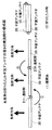
ここで、従来から知られている外部アンテナについて、図22を用いて説明する。 Here, a conventionally known external antenna will be described with reference to FIG.
従来の外部アンテナは、図22(1)に示すように、モノポール状のアンテナ(図中では、モノポールアンテナと言う。)であったり、図21(2)に示すように、平面状のアンテナ(図中では、平面アンテナと言う。)が知られている。 A conventional external antenna is a monopole antenna (referred to as a monopole antenna in the figure) as shown in FIG. 22 (1), or a planar antenna as shown in FIG. 21 (2). An antenna (referred to as a planar antenna in the figure) is known.
図22(1)のモノポール状のアンテナには、モノポールアンテナ600に同軸ケーブル501が接続され、先端に同軸コネクタ502が取り付けられている。これにより、このモノポールアンテナは、ドーナツ状の無指向性601を有しており、水平面内に無指向性の指向性を有するアンテナである。 In the monopole antenna of FIG. 22A, a coaxial cable 501 is connected to the monopole antenna 600, and a coaxial connector 502 is attached to the tip. Thereby, this monopole antenna has a donut-shaped omnidirectional 601 and is an antenna having omnidirectional directivity in a horizontal plane.
また、図22(2)の平面状のアンテナには、平面状の薄型の平面アンテナ500に同軸ケーブル501が接続され、先端に同軸コネクタ502が取り付けられている。これにより、この平面アンテナは、指向性503に示すような単一の指向性を持ち、1つの方向のみの指向性を有するアンテナであった。 Further, in the planar antenna of FIG. 22B, a coaxial cable 501 is connected to a planar thin planar antenna 500, and a coaxial connector 502 is attached to the tip. As a result, this planar antenna has a single directivity as indicated by directivity 503 and has directivity in only one direction.
ここで、一般的に、この平面アンテナの平面の面積の少ないアンテナは、利得が小さくブロードな指向性を有し、平面の面積が多いアンテナは、利得が大きく尖鋭な指向性を有している。 Here, in general, an antenna with a small planar area of this planar antenna has a broad directivity with a small gain, and an antenna with a large planar area has a sharp gain with a large gain. .
また、このアンテナの利得とは、同一電力を被測定アンテナと基準アンテナに加えた場合の電力の比で表される比のことを言う。アンテナは、入力されたエネルギーを一定方向に集中させることが出来るが、この集中のさせ方が、種類や個体、或いは形態などによって、受信における特徴的な差を生じる。 The gain of the antenna means a ratio expressed by a ratio of power when the same power is applied to the antenna to be measured and the reference antenna. The antenna can concentrate the input energy in a certain direction, but this concentration method causes a characteristic difference in reception depending on the type, individual, or form.
すなわち、入力された電力を通信相手以外の方向にもばら撒くアンテナと、指向性を持たせて電力を効率良く集中させるアンテナとでは、到達距離に差が発生する。この差が利得の差となり、利得が高ければ高いほど指向性が鋭くなり感度が向上すると共に、方向合わせが難しくなる事を意味している。 That is, there is a difference in reach between an antenna that distributes input power in directions other than the communication partner and an antenna that concentrates power efficiently by providing directivity. This difference becomes a difference in gain, and the higher the gain, the sharper the directivity and the higher the sensitivity, and the more difficult it is to align the direction.
従って、図22の従来のアンテナでは、(1)のような無指向性601という指向性か、(2)のような単一方向性503の指向性しか持たないので、いずれのアンテナであってもアンテナの指向性を変更することができなかった。また、図22(2)の平面アンテナは、方向合わせができても平面アンテナ500の面積を変更することが出来ないので、利得を高めると共に指向性を鋭くさせ、感度を向上することが出来なかった。 Therefore, the conventional antenna of FIG. 22 has only the directivity of omnidirectional 601 as in (1) or the directivity of unidirectional 503 as in (2). Even the antenna directivity could not be changed. In the planar antenna of FIG. 22 (2), since the area of the planar antenna 500 cannot be changed even if the direction can be aligned, the gain cannot be increased, the directivity can be sharpened, and the sensitivity cannot be improved. It was.
そこで、アンテナの指向性を変更することができるものや、或いは小型化を図ったアンテナ装置に関するものが、特許文献1及び2に記載されている。
ところで、特許文献1に記載された指向性制御アンテナ装置は、複数の平面アンテナがそれぞれ異なる方向に向くように配置され、スイッチを切り替えることにより動作させる平面アンテナを選択することを特徴としている。 By the way, the directivity control antenna device described in Patent Document 1 is characterized in that a plurality of planar antennas are arranged so as to be directed in different directions, and a planar antenna to be operated is selected by switching a switch.
しかしながら、この指向性制御アンテナ装置では、複数の平面アンテナがそれぞれ異なる方向を向いているので、ある1つのアンテナの方向合わせを行い、そのアンテナのみを動作させるように選択しても、1つの平面アンテナの面積は変わらず同じままである。 However, in this directivity control antenna apparatus, since a plurality of planar antennas are oriented in different directions, even if the direction of one antenna is aligned and only the antenna is selected to operate, one plane The area of the antenna remains the same.
従って、この指向性制御アンテナ装置では、1つの方向の電波に対して利得を大きくすることができないという問題があった。 Therefore, this directivity control antenna apparatus has a problem that the gain cannot be increased with respect to radio waves in one direction.
また、特許文献2に記載された平面アンテナ装置は、複数の平面アンテナをヒンジによって接合することにより、アンテナ部を形成したことを特徴とする平面アンテナ装置が記載されている。
Moreover, the planar antenna device described in
しかしながら、この平面アンテナ装置では、この平面アンテナ装置を携帯可能にするためにアンテナ部を折りたたんだに過ぎず、方向合わせを改善したり、利得を高めたりすることができないという問題があった。 However, in this planar antenna device, the antenna unit is merely folded in order to make the planar antenna device portable, and there is a problem that the direction alignment cannot be improved and the gain cannot be increased.
本発明は、上記問題に鑑みてなされたものであり、複数のアンテナを独立して制御し、指向性を変更することができると共に、コンパクトで平面上に収納することができる利便性の高い平面アンテナを提供することを目的とする。 The present invention has been made in view of the above problems, and can control a plurality of antennas independently to change directivity, and is a compact and highly convenient plane that can be stored on a plane. An object is to provide an antenna.
本発明に係る平面アンテナは、指向性を有する平面アンテナを複数備え、折りたたみ可能な平面アンテナ装置であって、各平面アンテナは、隣合う平面アンテナを蝶番によって回転角度を調整可能に接続されると共に、電波を受信可能な方向に対して変更可能に設定され、前記複数の平面アンテナを相互に組み合わせることによって指向性が制御され、前記複数の平面アンテナの指向性に基づいて、前記各平面アンテナに対応する前記電波を受信することを特徴とする。 The planar antenna according to the present invention is a foldable planar antenna device including a plurality of directional planar antennas, and each planar antenna is connected to an adjacent planar antenna so that the rotation angle can be adjusted by a hinge. The directionality can be changed with respect to the direction in which radio waves can be received, and the directivity is controlled by combining the plurality of planar antennas with each other, and each planar antenna is controlled based on the directivity of the plurality of planar antennas. It receives the said radio wave corresponding, It is characterized by the above-mentioned.
また本発明に係る平面アンテナは、前記複数の平面アンテナのうち、少なくとも2つ以上の前記平面アンテナが同一方向を受信するように設定され、前記電波を受信する利得を高めるようにしても良い。 The planar antenna according to the present invention may be set such that at least two or more of the planar antennas receive the same direction, and the gain for receiving the radio wave may be increased.
また本発明に係る平面アンテナは、前記隣合う平面アンテナが、前記蝶番によって相互に直角に配置可能に設定されるようにしても良い。 The planar antenna according to the present invention may be set such that the adjacent planar antennas can be arranged at right angles to each other by the hinge.
また本発明に係る平面アンテナは、前記複数の平面アンテナが、前記蝶番によって略環状になるように接続されるようにしても良い。 In the planar antenna according to the present invention, the plurality of planar antennas may be connected so as to be substantially annular by the hinge.
また本発明に係る平面アンテナは、前記複数の平面アンテナが、3つの前記平面アンテナによって構成されるようにしても良い。 In the planar antenna according to the present invention, the plurality of planar antennas may be constituted by the three planar antennas.
また本発明に係る平面アンテナは、前記複数の平面アンテナが受信した前記電波を合成する同軸ケーブルを更に備え、前記隣合う平面アンテナの背面又は上面に当該同軸ケーブルが備え付けられているようにしても良い。 The planar antenna according to the present invention may further include a coaxial cable for combining the radio waves received by the plurality of planar antennas, and the coaxial cable may be provided on the back surface or the upper surface of the adjacent planar antenna. good.
また本発明に係る平面アンテナは、前記同軸ケーブルが、前記各平面アンテナの内部に埋没されると共に、前記隣合う平面アンテナの側面を介して接続されるようにしても良い。 In the planar antenna according to the present invention, the coaxial cable may be buried in each planar antenna and connected via a side surface of the adjacent planar antenna.
また本発明に係る平面アンテナは、前記複数の平面アンテナが受信した前記電波を合成するプリント基板を更に備え、前記隣合う平面アンテナに当該プリント基板が接続されて備え付けられているようにしても良い。 The planar antenna according to the present invention may further include a printed circuit board that combines the radio waves received by the plurality of planar antennas, and the printed circuit board is connected to the adjacent planar antenna. .
また本発明に係る平面アンテナは、前記各平面アンテナが、前記同軸ケーブルを接続するコネクタを更に備え、受信する前記電波の指向性を変更する場合には、前記コネクタを介して、長さの異なる前記同軸ケーブルによって合成するようにしても良い。 The planar antenna according to the present invention further includes a connector for connecting the coaxial cable to each of the planar antennas. When the directivity of the received radio wave is changed, the planar antennas have different lengths via the connector. You may make it synthesize | combine with the said coaxial cable.
また本発明に係る平面アンテナは、前記各平面アンテナが、電力を分配する機能を備えた同軸ケーブルを更に備え、前記各平面アンテナに独立したアンテナとして機能するようにしても良い。 The planar antenna according to the present invention may further include a coaxial cable having a function of distributing power, and each planar antenna may function as an antenna independent of each planar antenna.
また本発明に係る平面アンテナは、前記各平面アンテナが、それぞれ独立して接続される同軸ケーブルを更に備え、前記複数の平面アンテナによって複数の前記電波をそれぞれ受信するようにしても良い。 The planar antenna according to the present invention may further include a coaxial cable in which each of the planar antennas is independently connected, and each of the plurality of planar antennas may receive the plurality of radio waves.
また本発明に係る平面アンテナは、前記蝶番が、前記隣合う平面アンテナの側面に備えられていると共に、前記複数の平面アンテナを同一平面側に折りたたむようにしても良い。 In the planar antenna according to the present invention, the hinge may be provided on a side surface of the adjacent planar antenna, and the plurality of planar antennas may be folded on the same plane side.
また本発明に係る平面アンテナは、前記蝶番が、前記隣合う平面アンテナの側面に備えられていると共に、前記複数の平面アンテナを互い違いに折りたたむようにしても良い。 In the planar antenna according to the present invention, the hinge may be provided on a side surface of the adjacent planar antenna, and the plurality of planar antennas may be folded alternately.
また本発明に係る平面アンテナは、前記蝶番が、前記隣合う平面アンテナの表面又は背面に備えられていると共に、前記複数の平面アンテナを互い違いに折りたたむようにしても良い。 In the planar antenna according to the present invention, the hinge may be provided on the front surface or the back surface of the adjacent planar antenna, and the plurality of planar antennas may be alternately folded.
また本発明に係る平面アンテナは、前記複数の平面アンテナのうち、外部から取得する送信用電波を送信可能な平面アンテナを少なくとも1つ備え、前記電波を受信すると共に、前記送信用電波を送信するようにしても良い。 The planar antenna according to the present invention includes at least one planar antenna capable of transmitting a transmission radio wave acquired from the outside of the plurality of planar antennas, and receives the radio wave and transmits the transmission radio wave. You may do it.
本発明によれば、指向性を有する平面アンテナを独立して受信する方向を制御することにより、指向性を変更することができるだけでなく、高利得な特性を得ることができるので、通信品質を向上することができる。かくして、複数のアンテナをそれぞれ独立して制御し、指向性を変更することができると共に、コンパクトで平面上に収納することができる利便性の高い平面アンテナを実現できる。 According to the present invention, by controlling the direction in which a planar antenna having directivity is received independently, not only can the directivity be changed, but also high gain characteristics can be obtained. Can be improved. Thus, it is possible to control a plurality of antennas independently to change the directivity, and to realize a compact and highly convenient planar antenna that can be stored on a plane.
本発明の平面アンテナは、折りたたみ可能であって、WiMAX端末、PDA端末や携帯電話などの通信端末の外部アンテナとして用いることを目的としている。 The planar antenna of the present invention is foldable and is intended to be used as an external antenna of a communication terminal such as a WiMAX terminal, a PDA terminal, or a mobile phone.
そして、また本発明の折りたたみ平面アンテナは、平面状のアンテナを、複数接続し、それらを、1枚の平面に折りたたみ可能な構造としたものである。それぞれの平面アンテナは、お互いの接合部において、その回転角度を任意に調整できる連結部を有している。 In addition, the folding planar antenna of the present invention has a structure in which a plurality of planar antennas are connected and can be folded into a single plane. Each of the planar antennas has a connecting portion that can arbitrarily adjust the rotation angle at the joint portion.
そして、それぞれの平面アンテナは、ブロードな指向性を有している。この構造により、それぞれ平面アンテナを同じ向きに調節すれば、先鋭で利得の高いアンテナが構成できる。また、それぞれの平面アンテナを、円周上に配置すれば、すなわち、2枚の時は背中合わせに、3枚の時は上から観て三角形に、4枚のときは上から観て正方形に配置すれば、無指向性を形成することができる。
(第1の実施例)
(1)折りたたみ平面アンテナ1の構成
図1は、本発明に係る平面アンテナの第1の実施例(以下、折りたたみ平面アンテナ1と言う。)を示す構成図である。図1に示す折りたたみ平面アンテナ1は、3枚の平面アンテナ10、20及び30と、連結部2と、足3と、連結部4と、同軸ケーブル5と、同軸ケーブル6と、コネクタ7とを備えている。
Each planar antenna has a broad directivity. With this structure, if each planar antenna is adjusted in the same direction, a sharp and high gain antenna can be configured. In addition, if each planar antenna is arranged on the circumference, it is arranged back-to-back when there are two antennas, triangular when viewed from the top when three antennas, and square when viewed from above when it is four antennas Then, omnidirectionality can be formed.
(First embodiment)
(1) Configuration of Folding Planar Antenna 1 FIG. 1 is a configuration diagram showing a first embodiment (hereinafter referred to as a folding planar antenna 1) of a planar antenna according to the present invention. A folding planar antenna 1 shown in FIG. 1 includes three planar antennas 10, 20, and 30, a connecting
ここで、3枚の平面アンテナ10、20及び30は、連結部2によって接続されている。
Here, the three planar antennas 10, 20 and 30 are connected by the connecting
連結部2は、蝶番(ちょうつがい)のような構造になっており、平面アンテナ10、20及び30を水平方向に折りたたんだり、相対的な設置角度を任意に設定できるように可動できるようになっている。
The connecting
平面アンテナ20及び30には、平面アンテナ自身が倒れないように、連結部4を介して足3が付加されている。 A foot 3 is added to the planar antennas 20 and 30 via the connecting portion 4 so that the planar antenna itself does not fall down.
この足3は、平面アンテナ10、20及び30の底面が平面状で十分安定に自立できれば、不要である。 This foot 3 is not necessary if the bottom surfaces of the planar antennas 10, 20, and 30 are planar and can stand up sufficiently stably.
連結部4は、足3を折りたたんで収納できるように、水平方向に回転可動可能な構造になっている。 The connecting portion 4 has a structure that can be rotated in the horizontal direction so that the foot 3 can be folded and stored.
同軸ケーブル5は、平面アンテナ20及び30に接続されて備えられており、それぞれ平面アンテナ10に接続される。 The coaxial cable 5 is provided connected to the planar antennas 20 and 30, and is connected to the planar antenna 10.
同軸ケーブル6は、平面アンテナ10に接続されて備えられており、その先端には、コネクタ7が設けられている。 The coaxial cable 6 is provided connected to the planar antenna 10, and a connector 7 is provided at the tip thereof.
平面アンテナ20及び30で受信された電波は、いったん平面アンテナ10の中の給電回路(図示せず)に取り込まれ、平面アンテナ10で受信した電波と同位相で合成されて、同軸ケーブル6に伝送され、コネクタ7に出力される。 The radio waves received by the planar antennas 20 and 30 are once taken into a feeding circuit (not shown) in the planar antenna 10, synthesized in the same phase as the radio waves received by the planar antenna 10, and transmitted to the coaxial cable 6. And output to the connector 7.
同様に、平面アンテナ10、20及び30から送信する場合には、コネクタ7に給電された送信電力が、同位相で平面アンテナ10、20及び30から放射されることになる。 Similarly, when transmitting from the planar antennas 10, 20 and 30, the transmission power fed to the connector 7 is radiated from the planar antennas 10, 20 and 30 in the same phase.
次に図2では、平面アンテナ10の構造の一実施例を示したものである。図2に示す平面アンテナ10の構造では、例えば、ポリカーボネイトやアクリルなどのプラスチック等の誘電体から構成される凹状の筐体11と、プリント基板12と、カバー13とを備えている。
Next, FIG. 2 shows an embodiment of the structure of the planar antenna 10. In the structure of the planar antenna 10 shown in FIG. 2, for example, a concave casing 11 made of a dielectric such as polycarbonate or acrylic, a printed circuit board 12, and a
図2(1)は、平面アンテナ10の断面図を示したものであり、図2(2)は、筐体11の斜視図であり、図2(3)は、カバー13の斜視図である。
2A is a cross-sectional view of the planar antenna 10, FIG. 2B is a perspective view of the housing 11, and FIG. 2C is a perspective view of the
図2(1)に示す平面アンテナ10のプリント基板12は、その表面に平面アンテナの放射素子や給電線路としてのマイクロストリップラインがエッチングによって形成されている。 The printed circuit board 12 of the planar antenna 10 shown in FIG. 2A is formed by etching a radiating element of the planar antenna and a microstrip line as a feed line on the surface.
そして、カバー13は、背面のふたに相当する部分であり、金属のような導体でも、プラスチックのような誘電体でも使用可能である。またカバー13には、図2(3)に示すように同軸ケーブル5及び6を通す穴14が設けられている。
The
ここで、図1の平面アンテナ20及び30は、図2に示した平面アンテナ10と構造的には同様である。 Here, the planar antennas 20 and 30 in FIG. 1 are structurally similar to the planar antenna 10 shown in FIG.
次に図3は、図2のプリント基板12の構造を示したものである。図3(1)に示すように、プリント基板12の表面には、4つのパッチアンテナ15と、マイクロストリップライン16と、グランド17とがエッチング等により形成されている。 Next, FIG. 3 shows the structure of the printed circuit board 12 of FIG. As shown in FIG. 3A, four patch antennas 15, microstrip lines 16, and grounds 17 are formed on the surface of the printed circuit board 12 by etching or the like.
また、グランド17は、複数のスルーホール18により、裏面の導体よりなるグランド21に導通している。 The ground 17 is electrically connected to a ground 21 made of a conductor on the back surface through a plurality of through holes 18.
図3(1)に示すプリント基板12の下部にある穴19は、同軸ケーブル5及び6の通る穴である。 A hole 19 in the lower part of the printed circuit board 12 shown in FIG. 3A is a hole through which the coaxial cables 5 and 6 pass.
図3(2)に示すプリント基板12の裏面は、グランド21によってアースとして接地されている。 The back surface of the printed circuit board 12 shown in FIG. 3B is grounded as a ground by a ground 21.
次に図4は、平面アンテナ20に用いる場合のプリント基板22の詳細構造を示している。図4(1)に示すプリント基板22の表面には、図3(1)と同様に、4つのパッチアンテナ23と、マイクロストリップライン24と、グランド25とがエッチング等により形成されている。 Next, FIG. 4 shows a detailed structure of the printed circuit board 22 when used for the planar antenna 20. On the surface of the printed circuit board 22 shown in FIG. 4A, four patch antennas 23, a microstrip line 24, and a ground 25 are formed by etching or the like, as in FIG.
また、グランド25は、複数のスルーホール26により、裏面の導体よりなるグランド27に導通している。 The ground 25 is electrically connected to a ground 27 made of a conductor on the back surface through a plurality of through holes 26.
図4(1)に示すプリント基板22の下部にある穴28は、同軸ケーブル5の通る穴である。 A hole 28 in the lower part of the printed board 22 shown in FIG. 4A is a hole through which the coaxial cable 5 passes.
図4(2)に示すプリント基板22の裏面は、グランド27によってアースとして接地されている。 The back surface of the printed circuit board 22 shown in FIG. 4B is grounded as a ground by a ground 27.
また平面アンテナ30に用いる場合のプリント基板は、本プリント基板22と線対称の構造にすればよい。 Further, the printed circuit board used for the planar antenna 30 may have a symmetrical structure with the printed circuit board 22.
次に図5は、平面アンテナ20における、プリント基板22と同軸ケーブル5との接続構造を示したものである。 Next, FIG. 5 shows a connection structure between the printed circuit board 22 and the coaxial cable 5 in the planar antenna 20.
図5の同軸ケーブル5は、同軸ケーブル5の接続される平面アンテナ20への接続側端をカバー23の穴29を通し、更に、プリント基板22のグランド27のある側から通して、プリント基板22の表面側で接続する。 5 passes through the hole 29 of the cover 23 through the connection side end to the planar antenna 20 to which the coaxial cable 5 is connected, and further passes from the side where the ground 27 of the printed circuit board 22 is provided. Connect on the front side.
このとき、プリント基板22の表面は、同軸ケーブル5の同軸外部導体40をグランド25にハンダ付けし、同軸中心導体41をマイクロストリップライン24にハンダ付けで接続する。 At this time, on the surface of the printed circuit board 22, the coaxial outer conductor 40 of the coaxial cable 5 is soldered to the ground 25 and the coaxial center conductor 41 is connected to the microstrip line 24 by soldering.
このように接続することにより、プリント基板22とカバー23は、図2に示したように平面アンテナ10と同様な筐体11を前面にして組み立てることができる。
(2)折りたたみ平面アンテナ1の動作
次に、折りたたみ平面アンテナ1の動作について、図6を用いて説明する。図6は、折りたたみ平面アンテナ1の第1の実施例の使用方法を示したものである。
By connecting in this way, the printed circuit board 22 and the cover 23 can be assembled with the casing 11 similar to the planar antenna 10 as shown in FIG.
(2) Operation of Folding Planar Antenna 1 Next, the operation of the folding flat antenna 1 will be described with reference to FIG. FIG. 6 shows a method of using the first embodiment of the folding planar antenna 1.
図6に示す折りたたみ平面アンテナ1は、平面アンテナ10、20及び30が、それぞれ、該当するブロードな放射指向性301、302及び303を有している。 In the folding planar antenna 1 shown in FIG. 6, the planar antennas 10, 20, and 30 have corresponding broad radiation directivities 301, 302, and 303, respectively.
そして更に、各平面アンテナ10、20及び30が、図6(1)の置き方のように同じ方向に向けられ、同位相で合成されることによって、図6(2)の指向性に示すように、指向性304のようなシャープで高利得な特性が得られる。 Further, the planar antennas 10, 20 and 30 are directed in the same direction as shown in FIG. 6 (1) and synthesized in the same phase, so that the directivity shown in FIG. 6 (2) is shown. In addition, a sharp and high gain characteristic such as directivity 304 can be obtained.
従って、電波の強い方向などがわかる場合には、図6(1)のように3枚の平面アンテナ10、20及び30をそれぞれ同じ方向に向けて使用することにより、利得を高めて指向性が鋭くなると共に感度が向上するので、通信品質を向上させることができる。 Accordingly, when the direction in which the radio wave is strong is known, the gain is increased and the directivity is increased by using the three planar antennas 10, 20 and 30 in the same direction as shown in FIG. The sharpness and the sensitivity are improved, so that the communication quality can be improved.
また、次の図7は、本発明の折りたたみ平面アンテナの第1の実施例の使用方法について、2つ目の方法を示したものである。図6の説明と同様に、図7に示す折りたたみ平面アンテナ1は、平面アンテナ10、20及び30が、それぞれ、該当するブロードな放射指向性301、302及び303を有している。 FIG. 7 shows a second method of using the folding planar antenna according to the first embodiment of the present invention. As in the description of FIG. 6, in the folding planar antenna 1 shown in FIG. 7, the planar antennas 10, 20, and 30 have corresponding broad radiation directivities 301, 302, and 303, respectively.
しかし、これらの平面アンテナ10、20及び30が、図7(1)の置き方のように、コの字状に置かれた場合には、平面アンテナ10、20及び30の電波は、それぞれ正対する方向に放射される。 However, when these planar antennas 10, 20 and 30 are placed in a U-shape as shown in FIG. 7 (1), the radio waves of the planar antennas 10, 20 and 30 are respectively positive. Radiated in the opposite direction.
これにより、折りたたみ平面アンテナ1は、平面アンテナ10、20及び30の指向性がブロードなため、隣接するアンテナの境目の角度でも、平面アンテナの利得の最大値より、概ね3〜4dB程度の軽微の減少で済み、利得がわずかに落ちる程度にとどまる(ただし、この劣化具合は、平面アンテナの大きさと利得、ビーム幅で決まるので、平面アンテナの大きさにより異なる。)。 Thereby, since the directivity of the planar antennas 10, 20, and 30 is broad, the folding planar antenna 1 is slightly smaller than the maximum value of the planar antenna by about 3 to 4 dB even at the angle between the adjacent antennas. It can be reduced and the gain is only slightly reduced (however, this deterioration depends on the size of the planar antenna, the gain, and the beam width, and thus depends on the size of the planar antenna).
そして、この境目の方向では、隣接する2つのアンテナの指向性が合成されるので、結果として、利得は、2倍の3dBが増加することになり、結局、この境目の方向での利得は、平面アンテナ正面方向とあまり変わらない値となる。 And since the directivity of two adjacent antennas is combined in the direction of this boundary, as a result, the gain increases by 3 dB, which is twice as a result. The value is not so different from the front direction of the planar antenna.
これにより、図7(1)のように3枚の平面アンテナ10、20及び30をコの字状に配置することによって、図7(2)で示したように、概ね270度の方向をカバーできる指向性を形成できる。 Thus, by arranging the three planar antennas 10, 20, and 30 in a U-shape as shown in FIG. 7 (1), the direction of about 270 degrees is covered as shown in FIG. 7 (2). Directivity that can be formed.
また、次の図8は、本発明の折りたたみ平面アンテナ1の第1の実施例の使用方法について、3つ目の方法を示したものである。図6でした説明と同様に、図8に示す折りたたみ平面アンテナ1は、平面アンテナ10、20及び30が、それぞれ、該当するブロードな放射指向性301、302及び303を有している。 FIG. 8 shows a third method of using the first embodiment of the folding planar antenna 1 of the present invention. Similar to the description in FIG. 6, in the folded planar antenna 1 shown in FIG. 8, the planar antennas 10, 20, and 30 have corresponding broad radiation directivities 301, 302, and 303, respectively.
しかし、これらの平面アンテナ10、20及び30が、図8(1)の置き方のように、三角形状に置かれた場合には、平面アンテナ10、20及び30の電波は、それぞれ正対する方向に放射される。 However, when these planar antennas 10, 20 and 30 are placed in a triangular shape as shown in FIG. 8 (1), the radio waves of the planar antennas 10, 20 and 30 face each other. To be emitted.
これにより、折りたたみ平面アンテナ1は、平面アンテナ10、20及び30の指向性がブロードなため、隣接するアンテナの境目の角度でも、平面アンテナの利得の最大値より、概ね4〜5dB程度の軽微の減少で済み、利得がわずかに落ちる程度にとどまる(ただし、この劣化具合は、平面アンテナの大きさと利得、ビーム幅で決まるので、平面アンテナの大きさにより異なる。)。 Thereby, since the directivity of the planar antennas 10, 20 and 30 is broad, the folding planar antenna 1 has a lightness of about 4 to 5 dB from the maximum value of the planar antenna even at the angle between the borders of adjacent antennas. It can be reduced and the gain is only slightly reduced (however, this deterioration depends on the size of the planar antenna, the gain, and the beam width, and thus depends on the size of the planar antenna).
そして、この境目の方向では、隣接する2つのアンテナの指向性が合成されるので、結果として、利得は、2倍の3dBが増加することになり、結局、この境目の方向での利得は、平面アンテナ正面方向とあまり変わらないか、わずかに劣化する程度の値となる。 And since the directivity of two adjacent antennas is combined in the direction of this boundary, as a result, the gain increases by 3 dB, which is twice as a result. It is a value that is not much different from the front direction of the planar antenna or slightly deteriorates.
これにより、図8(1)のように3枚の平面アンテナ10、20及び30を三角形状に配置することによって、図8(2)で示したように、概ね360度の方向をカバーできる指向性を形成できる。 Thus, by arranging the three planar antennas 10, 20, and 30 in a triangular shape as shown in FIG. 8A, the orientation that can cover the direction of approximately 360 degrees as shown in FIG. 8B. Can form sex.
以上のように、図7及び8の使用方法は、強い電波がどの方向からくるかわからない場合や、室内で使用する場合などにおいて、反射した多数の電波を沢山受信したい場合に有効である。 As described above, the method of use in FIGS. 7 and 8 is effective when it is desired to receive a large number of reflected radio waves when it is not known from which direction the strong radio waves come from, or when used indoors.
以上説明したように、本発明によれば、平面状のアンテナを、複数接続し、折りたたみ可能な構造としたことにより、それぞれの平面アンテナの方向を調整して、受信する電波の指向性を変更すると共に、調整することができる。
(第2の実施例)
次に、本発明の第2の実施例を図9に示す。図9に示す第2の実施例では、図1の第1の実施例に対し、同軸ケーブル5に相当する同軸ケーブル53が、平面アンテナ50、51及び52の上部に配置されている構造になっている。この場合、同軸ケーブルの引き込み構造は、図10のようになっている。
As described above, according to the present invention, a plurality of planar antennas are connected and foldable so that the direction of each planar antenna is adjusted to change the directivity of received radio waves. And can be adjusted.
(Second embodiment)
Next, a second embodiment of the present invention is shown in FIG. The second embodiment shown in FIG. 9 has a structure in which a coaxial cable 53 corresponding to the coaxial cable 5 is arranged above the planar antennas 50, 51 and 52, compared to the first embodiment of FIG. ing. In this case, the coaxial cable lead-in structure is as shown in FIG.
図10に示す同軸ケーブル53は、平面アンテナ50及び52の上部側面に設けられた穴55を通して、プリント基板12及び22に導かれ、図5の同軸中心導体と同軸外部導体を接続した場合と同様に取り付けられている。 The coaxial cable 53 shown in FIG. 10 is guided to the printed circuit boards 12 and 22 through the holes 55 provided on the upper side surfaces of the planar antennas 50 and 52, and is the same as the case where the coaxial center conductor and the coaxial outer conductor in FIG. Is attached.
これにより、第2の実施例では、第1の実施例に対し、同軸ケーブル53の太さ(厚み)を、平面アンテナの内部に取り込むことができるので、折りたたみ平面アンテナ1を薄くすることができる。
(第3の実施例)
次に、本発明の第3の実施例を図11に示す。図11に示す第3の実施例では、図1や図9において同軸ケ−ブル5が、外側で回り込むように接続されていたのに対し、図11の折りたたみ平面アンテナ1の平面アンテナ60が、隣り合う平面アンテナ61及び62の隣り合う側面部において、同軸ケーブル63によって最短距離になるように接続された構造である。
Thereby, in the second embodiment, the thickness (thickness) of the coaxial cable 53 can be taken into the plane antenna as compared with the first embodiment, so that the folding planar antenna 1 can be made thinner. .
(Third embodiment)
Next, a third embodiment of the present invention is shown in FIG. In the third embodiment shown in FIG. 11, the coaxial cable 5 is connected so as to wrap around on the outside in FIGS. 1 and 9, whereas the planar antenna 60 of the folding planar antenna 1 in FIG. In the adjacent side surfaces of the adjacent planar antennas 61 and 62, the coaxial cables 63 are connected so as to be the shortest distance.
すなわち、図11の第3の実施例では、同軸ケ−ブル63が、平面アンテナ60の隣り合う平面アンテナ61及び62との間に、それぞれ接続されている。 That is, in the third embodiment of FIG. 11, the coaxial cable 63 is connected between the adjacent planar antennas 61 and 62 of the planar antenna 60.
これにより、第3の実施例では、同軸ケーブル63を平面アンテナ60、61及び62に取り込むことができるので、同軸ケーブル63の衝撃による損傷や擦傷を回避することができる共に、折りたたみ平面アンテナ1のライフサイクル(寿命)を延ばすことができる。
(第4の実施例)
次に、本発明の第4の実施例を図12に示す。図12に示す第4の実施例では、図11において平面アンテナ60、61及び62が同軸ケ−ブル63によって接続されていたのに対し、フレキシブルなプリント基板で平面アンテナ70、71及び72を接続した実施例を示したものである。
As a result, in the third embodiment, the coaxial cable 63 can be taken into the planar antennas 60, 61 and 62, so that damage and scratches due to the impact of the coaxial cable 63 can be avoided and the folding planar antenna 1 Life cycle (life) can be extended.
(Fourth embodiment)
Next, a fourth embodiment of the present invention is shown in FIG. In the fourth embodiment shown in FIG. 12, the planar antennas 60, 61 and 62 in FIG. 11 are connected by the coaxial cable 63, whereas the planar antennas 70, 71 and 72 are connected by a flexible printed board. This embodiment is shown.
図12に示す第4の実施例における折りたたみ平面アンテナ1は、平面アンテナ70と、隣り合う平面アンテナ71及び72との接続において、接続用プリント基板A80と接続用プリント基板B90とが用いられている。 The folding planar antenna 1 in the fourth embodiment shown in FIG. 12 uses a connection printed circuit board A80 and a connection printed circuit board B90 for connection between the planar antenna 70 and the adjacent planar antennas 71 and 72. .
図12に示す平面アンテナ70、71及び72に用いられるプリント基板の構造の実施例を、図13に示す。 An example of the structure of the printed circuit board used for the planar antennas 70, 71 and 72 shown in FIG. 12 is shown in FIG.
図13(1)には、プリント基板75の表面を示し、図13(2)には、プリント基板76の表面を示す。プリント基板75の表面は、図13(1)に示すように、グランド77、78及び79と、マイクロストリップライン85等により形成されている。プリント基板76の表面は、図13(2)に示すように、グランド77及び78と、マイクロストリップライン86等により形成されている。 FIG. 13 (1) shows the surface of the printed circuit board 75, and FIG. 13 (2) shows the surface of the printed circuit board 76. As shown in FIG. 13A, the surface of the printed circuit board 75 is formed by grounds 77, 78 and 79, a microstrip line 85, and the like. As shown in FIG. 13B, the surface of the printed circuit board 76 is formed by grounds 77 and 78, a microstrip line 86, and the like.
このように、図12に示す平面アンテナ70には、図13に示すプリント基板75が用いられ、図12に示す平面アンテナ71及び72には、図13に示すプリント基板76が用いられる。 Thus, the printed circuit board 75 shown in FIG. 13 is used for the planar antenna 70 shown in FIG. 12, and the printed circuit board 76 shown in FIG. 13 is used for the planar antennas 71 and 72 shown in FIG.
そして図12に示す平面アンテナ70と71の接続は、図13に示すプリント基板75及び76の側面端に設けられているグランド77及び78に、図14に示す接続用プリント基板A80及び接続用プリント基板B90を接続することによってなされる。 The planar antennas 70 and 71 shown in FIG. 12 are connected to the grounds 77 and 78 provided at the side edges of the printed boards 75 and 76 shown in FIG. This is done by connecting the substrate B90.
図14(1)に示す接続用プリント基板A80は、折り曲げが可能なフレキシブルなプリント基板で構成され、その裏面は銅箔等の導体層が設けられている。この接続用プリント基板A80の銅箔等による導体層面の左右両端の一部を、図13に示したプリント基板75のグランド78とプリント基板76のグランド78部分とにハンダ付けすることにより、プリント基板75と76は物理的に接続される。 A printed circuit board A80 for connection shown in FIG. 14A is composed of a flexible printed circuit board that can be bent, and a conductor layer such as copper foil is provided on the back surface thereof. A part of the left and right ends of the conductor layer surface of the connection printed circuit board A80 made of copper foil or the like is soldered to the ground 78 of the printed circuit board 75 and the ground 78 portion of the printed circuit board 76 shown in FIG. 75 and 76 are physically connected.
同様に、図14(2)に示す接続用プリント基板B90も、折り曲げが可能なフレキシブルなプリント基板で構成されている。この接続用プリント基板B90は、表面にマイクロストリップライン91が配置され、その左右端にスルーホール92を有し、そのスルーホール92は、接続用プリント基板B90の裏側に達し、導体のランド94に導通している。 Similarly, the connection printed circuit board B90 shown in FIG. 14B is also formed of a flexible printed circuit board that can be bent. The connecting printed circuit board B90 has a microstrip line 91 disposed on the surface thereof, and has through holes 92 on the left and right ends thereof. The through holes 92 reach the back side of the connecting printed circuit board B90, and are formed on conductor lands 94. Conducted.
また、接続用プリント基板B90の裏側には、導体のグランド93が先のランド94を避けて配置されている。 Further, a conductor ground 93 is arranged on the back side of the connection printed circuit board B90 so as to avoid the land 94.
接続用プリント基板B90も、接続用プリント基板A80同様に、グランド93の両端部の一部を、図13のプリント基板75のグランド77とプリント基板76のグランド77部分にハンダ付けし、接続用プリント基板B90のランド94を、プリント基板75のマイクロストリップライン85の先端部とプリント基板76のマイクロストリップライン86の先端部にハンダ付けすることにより、接続用プリント基板A80は、プリント基板75と76を物理的にも電気的にも接続されたことになる。 Similarly to the connection printed circuit board A80, the connection printed circuit board B90 is also soldered to the ground 77 of the printed circuit board 75 and the ground 77 portion of the printed circuit board 76 in FIG. By soldering the land 94 of the substrate B90 to the tip of the microstrip line 85 of the printed circuit board 75 and the tip of the microstrip line 86 of the printed circuit board 76, the connecting printed circuit board A80 is connected to the printed circuit boards 75 and 76. It is physically and electrically connected.
この接続用プリント基板A80及び接続用プリント基板B90が、プリント基板75及びプリント基板76に接続された場合の構造を、図15に示す。
FIG. 15 shows the structure when the connection printed
これにより、第4の実施例では、同軸ケーブル63を使用する代わりに、接続用プリント基板A80と接続用プリント基板B90とによって平面アンテナ70、71及び72を接続することができるので、折りたたみ平面アンテナ1を軽量化し、小型化を図ることができる。
(第5の実施例)
次に、本発明の第5の実施例を図16に示す。図16に示す第5の実施例では、3枚の平面アンテナ100、110及び120が、連結部2によって接続されている。
Thus, in the fourth embodiment, instead of using the coaxial cable 63, the planar antennas 70, 71 and 72 can be connected by the connection printed circuit board A80 and the connection printed circuit board B90. 1 can be reduced in weight and reduced in size.
(Fifth embodiment)
Next, FIG. 16 shows a fifth embodiment of the present invention. In the fifth embodiment shown in FIG. 16, three planar antennas 100, 110, and 120 are connected by the connecting
連結部2は、図1と同様に、蝶番(ちょうつがい)のような構造になっており、平面アンテナ100、110及び120を水平方向に折りたたんだり、相対的な設置角度を任意に設定できるように可動できる構造になっている。
As in FIG. 1, the connecting
図16と図1との違いは、平面アンテナ110及び120が、同軸ケーブル112で直接的には接続されておらず、一旦、コネクタ111及び121を介して、同軸ケーブル112及び122によって接続されることである。 The difference between FIG. 16 and FIG. 1 is that the planar antennas 110 and 120 are not directly connected by the coaxial cable 112 but are once connected by the coaxial cables 112 and 122 via the connectors 111 and 121. That is.
同軸ケーブル112及び122は、同様に平面アンテナ100のコネクタ101、102にも接続され、平面アンテナ100は、平面アンテナ110及び120に、電気的に接続される。 The coaxial cables 112 and 122 are similarly connected to the connectors 101 and 102 of the planar antenna 100, and the planar antenna 100 is electrically connected to the planar antennas 110 and 120.
図16の場合では、同軸ケーブル112及び122の長さは、通常、平面アンテナ100、110及び120から放射される電波が同位相となるように設定される。 In the case of FIG. 16, the lengths of the coaxial cables 112 and 122 are normally set so that the radio waves radiated from the planar antennas 100, 110, and 120 have the same phase.
しかし、図16の場合において、あえて長さの異なる同軸ケーブルを用いることで、3つの平面アンテナから放射される合成の指向性を変化させる、すなわち、ビーム幅を広げたり、ビーム方向を右または左に向けたりすることが、可能になる。 However, in the case of FIG. 16, by using coaxial cables of different lengths, the combined directivity radiated from the three planar antennas is changed, that is, the beam width is expanded or the beam direction is changed to the right or left. It becomes possible to point to.
更に、平面アンテナ110と平面アンテナ120とに独立な同軸ケーブルで、MIMO(Multiple Input Multiple Output)技術の2つのアンテナとして使用することが可能になる。 Further, the coaxial antennas independent of the planar antenna 110 and the planar antenna 120 can be used as two antennas of MIMO (Multiple Input Multiple Output) technology.
なぜなら従来では、複数の平面アンテナを備えていても、1つの電波しか受信することしかできず、MIMO技術に対応できていないという問題があった。 This is because, conventionally, even if a plurality of planar antennas are provided, only one radio wave can be received and the MIMO technology cannot be supported.
ここで、MIMO技術とは、複数のアンテナで複数のデータの送受信を行なう無線通信技術のことであり、後述する実施例においてMIMO技術への対応を説明する。 Here, the MIMO technology is a wireless communication technology for transmitting and receiving a plurality of data with a plurality of antennas, and the correspondence to the MIMO technology will be described in an embodiment described later.
この第5の実施例では、図1で示した同軸ケーブル5及び6を使用する代わりに、コネクタ101及び102とコネクタ111及び121とを介して、同軸ケーブル103、112及び同軸ケーブル122を接続することにより、同軸ケーブル103、112及び同軸ケーブル122の長さに応じて、指向性を変化させることができる。
(第6の実施例)
次に、本発明の第6の実施例を図17に示す。図17に示す第6の実施例では、図16の構成に対し、中央の平面アンテナ130が1つのコネクタ131を有し、平面アンテナ110、120及び130へ、電力を3分配する機能をもった同軸ケーブル132によって、給電する構造としたものである。
In the fifth embodiment, instead of using the coaxial cables 5 and 6 shown in FIG. 1, the coaxial cables 103 and 112 and the coaxial cable 122 are connected via the connectors 101 and 102 and the connectors 111 and 121. Thus, the directivity can be changed according to the lengths of the coaxial cables 103 and 112 and the coaxial cable 122.
(Sixth embodiment)
Next, a sixth embodiment of the present invention is shown in FIG. In the sixth embodiment shown in FIG. 17, the central planar antenna 130 has one connector 131 and has the function of distributing power to the planar antennas 110, 120, and 130 in the configuration of FIG. In this structure, power is supplied by the coaxial cable 132.
この場合、平面アンテナ110、120及び130は、それぞれ独立のアンテナとしても使用可能で、3つのアンテナとして3チャネルのMIMO通信に対応できる。 In this case, the planar antennas 110, 120, and 130 can also be used as independent antennas, and can support three-channel MIMO communication as three antennas.
ここで、MIMO技術の動作について、図18を用いて説明する。図18は、MIMO技術を用いたMIMO通信を行う使用方法の一例である。 Here, the operation of the MIMO technique will be described with reference to FIG. FIG. 18 is an example of a usage method for performing MIMO communication using the MIMO technology.
図18の構成は、図17の平面アンテナ110、120及び130に、それぞれ独立した同軸コネクタ111、121及び131を備え、各同軸コネクタ111、121及び131に対応し、かつ独立した同軸ケーブル140、150及び160を、平面アンテナ110、120及び130に備えられたコネクタ端子111、121及び131に接続する。 The configuration of FIG. 18 includes independent coaxial connectors 111, 121, and 131 for the planar antennas 110, 120, and 130 of FIG. 17, corresponding to the coaxial connectors 111, 121, and 131, and independent coaxial cables 140, 150 and 160 are connected to connector terminals 111, 121, and 131 provided on the planar antennas 110, 120, and 130.
なお、MIMO技術による折りたたみ平面アンテナ1を使用する場合には、この折りたたみ平面アンテナ1と接続される装置(図示せず)にも、複数のアンテナ接続端子(図示せず)が設けられている。 In addition, when using the folding flat antenna 1 by MIMO technology, the apparatus (not shown) connected with this folding flat antenna 1 is also provided with a plurality of antenna connection terminals (not shown).
なぜなら、MIMO技術を使用する状況であって多数の反射波が存在する場合には、複数のアンテナを用いて多数の反射波を利用して通信することにより、通信品質や通信速度を向上させることができるので、上述のように、それぞれのアンテナを独立に用いることでMIMO技術を有効に用いて、通信品質や通信速度を改善することが可能になる。 Because in the situation where MIMO technology is used and a large number of reflected waves exist, communication quality and communication speed can be improved by using a plurality of antennas to communicate using a large number of reflected waves. Therefore, as described above, it is possible to improve the communication quality and the communication speed by effectively using the MIMO technique by using each antenna independently.
また、上述において、折りたたみ平面アンテナ1が接続される装置側のアンテナ接続端子が2つの場合には、3つ平面アンテナ110、120及び130のうち、任意の2つを選べばよい。また、MIMO技術を用いたMIMO通信では、使用し易い複数のアンテナ同士の相関が小さい方が有効であるため、図6乃至8で示したように、平面アンテナの向きを多方面に調整することにより、通信品質や通信速度の更なる改善を図ることができる。
(第7の実施例)
次に、本発明の第7の実施例を図19に示す。図19に示す第7の実施例では、平面アンテナの収納時の折りたたみ方を示した構成図である。
In the above description, when there are two antenna connection terminals on the apparatus side to which the folding planar antenna 1 is connected, any two of the three planar antennas 110, 120, and 130 may be selected. Also, in MIMO communication using the MIMO technology, it is effective that the correlation between a plurality of antennas that are easy to use is smaller. Therefore, as shown in FIGS. 6 to 8, the orientation of the planar antenna should be adjusted in many directions. As a result, communication quality and communication speed can be further improved.
(Seventh embodiment)
Next, a seventh embodiment of the present invention is shown in FIG. In the seventh embodiment shown in FIG. 19, it is a configuration diagram showing how to fold the flat antenna when it is housed.
図19(1)に示すように、折りたたみ平面アンテナ1は、平面アンテナ10、20及び30の接続をそれぞれのアンテナの側面で、連結部200及び201を使用して接続されている。 As shown in FIG. 19 (1), the folding planar antenna 1 is connected to the planar antennas 10, 20, and 30 on the side surfaces of the respective antennas using connecting portions 200 and 201.
これにより、第7の実施例の折りたたみ平面アンテナ1は、まず連結部201によって平面アンテナ30をA方向に折りたたみ、次に連結部200によって平面アンテナ20をB方向に折りたたむことができる。 Thereby, the folding planar antenna 1 of the seventh embodiment can first fold the planar antenna 30 in the A direction by the connecting portion 201 and then fold the planar antenna 20 in the B direction by the connecting portion 200.
そして、このように折りたたんだときに、平面アンテナ30の厚み分を挟み込むような寸法にしておけば、図19(2)折りたたみ時のように、1枚の平板状に収納することができて、携帯性、利便性を図ることができる。
(第8の実施例)
次に、本発明の第8の実施例を図20に示す。図20に示す第8の実施例では、平面アンテナの収納時の他の折りたたみ方を示した構成図である。
And, when it is folded in this way, if it is dimensioned so as to sandwich the thickness of the planar antenna 30, it can be stored in a single flat plate shape as in FIG. 19 (2), Portability and convenience can be achieved.
(Eighth embodiment)
Next, an eighth embodiment of the present invention is shown in FIG. The eighth embodiment shown in FIG. 20 is a configuration diagram showing another folding method when the planar antenna is stored.
ここで、図19との違いは、連結部210と211とが反対方向に可動するように取り付けられていることである。 Here, the difference from FIG. 19 is that the connecting portions 210 and 211 are attached so as to be movable in opposite directions.
これにより、折りたたみ平面アンテナ1は、平面アンテナ10に対して、連結部211によって先に平面アンテナ30をC方向に折りたたんでも良く、また或いは、連結部210によって平面アンテナ20をD方向に折りたたんでも良い。 Thereby, the flat planar antenna 1 may be folded first in the C direction by the connecting portion 211 with respect to the flat antenna 10, or may be folded in the D direction by the connecting portion 210. .
従って、第8の実施例の折りたたみ平面アンテナ1は、折りたたみの順番(C方向、又はD方向)を気にすることなく、図20(2)のように折りたたむことができる。
(第9の実施例)
次に、本発明の第9の実施例を図21に示す。図21に示す第9の実施例では、平面アンテナの収納時の他の折りたたみ方を示した構成図である。
Therefore, the folding planar antenna 1 of the eighth embodiment can be folded as shown in FIG. 20 (2) without worrying about the folding order (C direction or D direction).
(Ninth embodiment)
Next, FIG. 21 shows a ninth embodiment of the present invention. The ninth embodiment shown in FIG. 21 is a configuration diagram showing another folding method when the planar antenna is stored.
ここで、図20で示した折りたたみ方との違いは、連結部220と221の平面アンテナへの取り付けを、側面ではなく背面としたことである。 Here, the difference from the folding method shown in FIG. 20 is that the connecting portions 220 and 221 are attached to the planar antenna on the back surface instead of the side surface.
なぜなら、平面アンテナの厚みが非常に薄い平面アンテナの場合には、平面アンテナの側面に十分な強度を保つことが出来ない場合があり、このような場合には、アンテナ背面に連結部を固定することにより、強度不足を補完することができる。 This is because in the case of a flat antenna having a very thin planar antenna, sufficient strength may not be maintained on the side surface of the flat antenna. In such a case, the connecting portion is fixed to the back surface of the antenna. Thus, the lack of strength can be compensated.
具体的には、折りたたみ平面アンテナ1は、平面アンテナ10に対して、連結部221によって平面アンテナ30をE方向に折りたたみ、また連結部220によって平面アンテナ20をF方向に折りたたむことができる。 Specifically, the folded planar antenna 1 can fold the planar antenna 30 in the E direction by the connecting portion 221 and can fold the planar antenna 20 in the F direction by the connecting portion 220 with respect to the planar antenna 10.
これにより、厚みが非常に薄い平面アンテナの場合であっても、コンパクトに折りたたむことができるので、携帯性、利便性を図ることができる。 Thereby, even in the case of a flat antenna having a very thin thickness, it can be folded in a compact manner, so that portability and convenience can be achieved.
1 折りたたみ平面アンテナ
2 連結部
3 足
4 連結部
5、6 同軸ケーブル
7 コネクタ
10 平面アンテナ
11 筐体
12 プリント基板
13 カバー
14 穴
15 パッチアンテナ
16 マイクロストリップライン
17 グランド
18 スルーホール
19 穴
20 平面アンテナ
21 グランド
22 プリント基板
23 パッチアンテナ
24 マイクロストリップライン
25 グランド
26 スルーホール
27 グランド
28、29 穴
30 平面アンテナ
40 同軸外部導体
41 同軸中心導体
50、51、52 平面アンテナ
53 同軸ケーブル
55 穴
60、61、62 平面アンテナ
63 同軸ケーブル
70、71、72 平面アンテナ
75、76 プリント基板
77、78、79 プリント基板
80 接続用プリント基板A
83 グランド
85、86 マイクロストリップライン
90 接続用プリント基板B
91 マイクロストリップライン
92 スルーホールド
93 グランド
94 ランド
100、110、120 平面アンテナ
101、102、111、121 コネクタ
103、112、122 同軸ケーブル
130 平面アンテナ
131 コネクタ
132 同軸ケーブル
140、150、160 同軸ケーブル
200、201 連結部
210、211 連結部
220、221 連結部
301、302、303、304 指向性
500 平面アンテナ
501 同軸ケーブル
502 同軸コネクタ
503 単一指向性
600 モノポールアンテナ
601 ドーナツ状の無指向性
DESCRIPTION OF SYMBOLS 1
83 Ground 85, 86
91 Microstrip line 92 Through hold 93 Ground 94 Land 100, 110, 120 Planar antenna 101, 102, 111, 121 Connector 103, 112, 122 Coaxial cable 130 Planar antenna 131 Connector 132 Coaxial cable 140, 150, 160 Coaxial cable 200, 201 Coupling parts 210, 211 Coupling parts 220, 221 Coupling parts 301, 302, 303, 304 Directivity 500 Planar antenna 501 Coaxial cable 502 Coaxial connector 503 Unidirectional 600 Monopole antenna 601 Donut-shaped omnidirectional
Claims (15)
各平面アンテナは、隣合う平面アンテナを蝶番によって回転角度を調整可能に接続されると共に、電波を受信可能な方向に対して変更可能に設定され、
前記複数の平面アンテナを相互に組み合わせることによって指向性が制御され、
前記複数の平面アンテナの指向性に基づいて、前記各平面アンテナに対応する前記電波を受信する
ことを特徴とする平面アンテナ装置。 A planar antenna device that includes a plurality of planar antennas having directivity and is foldable,
Each planar antenna is connected so that the rotation angle of the adjacent planar antenna can be adjusted by a hinge and can be changed with respect to the direction in which radio waves can be received.
Directivity is controlled by combining the plurality of planar antennas with each other,
The planar antenna device, wherein the radio wave corresponding to each planar antenna is received based on directivity of the plurality of planar antennas.
ことを特徴とする請求項1記載の平面アンテナ装置。 2. The planar antenna device according to claim 1, wherein among the plurality of planar antennas, at least two or more planar antennas are set to receive the same direction, and the gain for receiving the radio wave is increased.
Priority Applications (1)
| Application Number | Priority Date | Filing Date | Title |
|---|---|---|---|
| JP2006294459A JP2008113187A (en) | 2006-10-30 | 2006-10-30 | Flat antenna device |
Applications Claiming Priority (1)
| Application Number | Priority Date | Filing Date | Title |
|---|---|---|---|
| JP2006294459A JP2008113187A (en) | 2006-10-30 | 2006-10-30 | Flat antenna device |
Publications (1)
| Publication Number | Publication Date |
|---|---|
| JP2008113187A true JP2008113187A (en) | 2008-05-15 |
Family
ID=39445469
Family Applications (1)
| Application Number | Title | Priority Date | Filing Date |
|---|---|---|---|
| JP2006294459A Pending JP2008113187A (en) | 2006-10-30 | 2006-10-30 | Flat antenna device |
Country Status (1)
| Country | Link |
|---|---|
| JP (1) | JP2008113187A (en) |
Cited By (10)
| Publication number | Priority date | Publication date | Assignee | Title |
|---|---|---|---|---|
| JP2008172708A (en) * | 2007-01-15 | 2008-07-24 | Yagi Antenna Co Ltd | Portable antenna |
| JP2010203801A (en) * | 2009-02-27 | 2010-09-16 | Nec Corp | Radar device, method of controlling radar, and program |
| JP2012090253A (en) * | 2010-09-24 | 2012-05-10 | Nihon Univ | Deployable phased-array antenna |
| WO2017135368A1 (en) * | 2016-02-05 | 2017-08-10 | 株式会社Nttドコモ | Wireless communication device |
| JP2017224943A (en) * | 2016-06-14 | 2017-12-21 | APRESIA Systems株式会社 | Broadcast antenna equipment |
| KR20190002035A (en) * | 2017-06-29 | 2019-01-08 | 홍익대학교 산학협력단 | Antenna for changing ploarisation using hinge |
| WO2020031776A1 (en) * | 2018-08-06 | 2020-02-13 | 株式会社村田製作所 | Antenna module |
| WO2020170722A1 (en) * | 2019-02-20 | 2020-08-27 | 株式会社村田製作所 | Antenna module, communication device on which antenna module is mounted, and method for manufacturing antenna module |
| WO2022038879A1 (en) * | 2020-08-21 | 2022-02-24 | 株式会社村田製作所 | Antenna module and communication device equipped with same |
| JP2022106019A (en) * | 2021-01-06 | 2022-07-19 | 東芝テック株式会社 | Antenna device |
-
2006
- 2006-10-30 JP JP2006294459A patent/JP2008113187A/en active Pending
Cited By (31)
| Publication number | Priority date | Publication date | Assignee | Title |
|---|---|---|---|---|
| JP2008172708A (en) * | 2007-01-15 | 2008-07-24 | Yagi Antenna Co Ltd | Portable antenna |
| JP2010203801A (en) * | 2009-02-27 | 2010-09-16 | Nec Corp | Radar device, method of controlling radar, and program |
| JP2012090253A (en) * | 2010-09-24 | 2012-05-10 | Nihon Univ | Deployable phased-array antenna |
| WO2017135368A1 (en) * | 2016-02-05 | 2017-08-10 | 株式会社Nttドコモ | Wireless communication device |
| JP2017224943A (en) * | 2016-06-14 | 2017-12-21 | APRESIA Systems株式会社 | Broadcast antenna equipment |
| KR20190002035A (en) * | 2017-06-29 | 2019-01-08 | 홍익대학교 산학협력단 | Antenna for changing ploarisation using hinge |
| KR101952208B1 (en) * | 2017-06-29 | 2019-02-26 | 홍익대학교 산학협력단 | Antenna for changing ploarisation using hinge |
| CN112534642A (en) * | 2018-08-06 | 2021-03-19 | 株式会社村田制作所 | Antenna module |
| WO2020031776A1 (en) * | 2018-08-06 | 2020-02-13 | 株式会社村田製作所 | Antenna module |
| CN112534642B (en) * | 2018-08-06 | 2024-06-18 | 株式会社村田制作所 | Antenna module |
| US11581635B2 (en) | 2018-08-06 | 2023-02-14 | Murata Manufacturing Co., Ltd. | Antenna module |
| JP7047918B2 (en) | 2018-08-06 | 2022-04-05 | 株式会社村田製作所 | Antenna module |
| JPWO2020031776A1 (en) * | 2018-08-06 | 2021-08-02 | 株式会社村田製作所 | Antenna module |
| KR102197563B1 (en) | 2019-02-20 | 2020-12-31 | 가부시키가이샤 무라타 세이사쿠쇼 | Antenna module, communication device mounted thereon, and manufacturing method of antenna module |
| JP6773259B1 (en) * | 2019-02-20 | 2020-10-21 | 株式会社村田製作所 | Antenna module, communication device equipped with it, and manufacturing method of antenna module |
| KR102241159B1 (en) | 2019-02-20 | 2021-04-16 | 가부시키가이샤 무라타 세이사쿠쇼 | Antenna module, communication device equipped with the same, and manufacturing method of antenna module |
| CN112106250B (en) * | 2019-02-20 | 2021-07-09 | 株式会社村田制作所 | Antenna module, communication device having the same mounted thereon, and method for manufacturing antenna module |
| KR20200145853A (en) * | 2019-02-20 | 2020-12-30 | 가부시키가이샤 무라타 세이사쿠쇼 | Antenna module, communication device equipped with the same, and manufacturing method of antenna module |
| KR20210118053A (en) * | 2019-02-20 | 2021-09-29 | 가부시키가이샤 무라타 세이사쿠쇼 | Antenna module, communication device equipped with the same, and manufacturing method of antenna module |
| KR20200103844A (en) * | 2019-02-20 | 2020-09-02 | 가부시키가이샤 무라타 세이사쿠쇼 | Antenna module, communication device mounted thereon, and manufacturing method of antenna module |
| US12009608B2 (en) | 2019-02-20 | 2024-06-11 | Murata Manufacturing Co., Ltd. | Antenna module, communication device equipped with the same, and manufacturing method of antenna module |
| CN112106250A (en) * | 2019-02-20 | 2020-12-18 | 株式会社村田制作所 | Antenna module, communication device having the same mounted thereon, and method for manufacturing antenna module |
| WO2020170722A1 (en) * | 2019-02-20 | 2020-08-27 | 株式会社村田製作所 | Antenna module, communication device on which antenna module is mounted, and method for manufacturing antenna module |
| KR102599495B1 (en) | 2019-02-20 | 2023-11-08 | 가부시키가이샤 무라타 세이사쿠쇼 | Antenna module, communication device equipped with the same, and manufacturing method of antenna module |
| US11611147B2 (en) | 2019-02-20 | 2023-03-21 | Murata Manufacturing Co., Ltd. | Antenna module, communication device equipped with the same, and manufacturing method of antenna module |
| JP7537501B2 (en) | 2020-08-21 | 2024-08-21 | 株式会社村田製作所 | Antenna module and communication device equipped with same |
| US12218432B2 (en) | 2020-08-21 | 2025-02-04 | Murata Manufacturing Co., Ltd. | Antenna module and communication apparatus equipped with the same |
| JPWO2022038879A1 (en) * | 2020-08-21 | 2022-02-24 | ||
| WO2022038879A1 (en) * | 2020-08-21 | 2022-02-24 | 株式会社村田製作所 | Antenna module and communication device equipped with same |
| JP2022106019A (en) * | 2021-01-06 | 2022-07-19 | 東芝テック株式会社 | Antenna device |
| JP7483639B2 (en) | 2021-01-06 | 2024-05-15 | 東芝テック株式会社 | Antenna Device |
Similar Documents
| Publication | Publication Date | Title |
|---|---|---|
| EP1782499B1 (en) | System and method for an omnidirectional planar antenna apparatus with selectable elements | |
| US10219389B2 (en) | Electronic device having millimeter wave antennas | |
| US7215296B2 (en) | Switched multi-beam antenna | |
| US6380896B1 (en) | Circular polarization antenna for wireless communication system | |
| CN102403566A (en) | Directional antenna and intelligent antenna system | |
| JP2008085869A (en) | Portable wireless device | |
| JP2006504353A (en) | Antenna array | |
| CN115458905B (en) | Antenna device and electronic equipment | |
| CN101385201A (en) | Wireless Access Point with Enhanced Coverage | |
| JP4446203B2 (en) | Antenna element and broadband antenna device | |
| US8836593B2 (en) | Diversity fin antenna | |
| JP4215749B2 (en) | A portable terminal equipped with a satellite receiving antenna | |
| EP1841006A1 (en) | Mobile wireless unit | |
| JP2008113187A (en) | Flat antenna device | |
| CN118539140A (en) | Electronic equipment and protective housing | |
| JP2006166261A (en) | Portable radio | |
| CN116388842A (en) | Electronic equipment | |
| JP2004096572A (en) | Indoor mobile communication device | |
| JPWO2009130775A1 (en) | Planar antenna device and communication device | |
| CN118472636A (en) | Electronic equipment | |
| JP3880295B2 (en) | Chip antenna | |
| US20060170601A1 (en) | Mobile communication devices | |
| JP2005295188A (en) | Multi-beam antenna | |
| US20260023408A1 (en) | Electronic device | |
| TWI292640B (en) | Solid flat antenna |
Legal Events
| Date | Code | Title | Description |
|---|---|---|---|
| A521 | Written amendment |
Effective date: 20080311 Free format text: JAPANESE INTERMEDIATE CODE: A523 |
|
| A02 | Decision of refusal |
Effective date: 20080520 Free format text: JAPANESE INTERMEDIATE CODE: A02 |
|
| RD01 | Notification of change of attorney |
Free format text: JAPANESE INTERMEDIATE CODE: A7421 Effective date: 20080604 |