JP2008082855A - Fall detection device for saddle riding type vehicles - Google Patents
Fall detection device for saddle riding type vehicles Download PDFInfo
- Publication number
- JP2008082855A JP2008082855A JP2006262601A JP2006262601A JP2008082855A JP 2008082855 A JP2008082855 A JP 2008082855A JP 2006262601 A JP2006262601 A JP 2006262601A JP 2006262601 A JP2006262601 A JP 2006262601A JP 2008082855 A JP2008082855 A JP 2008082855A
- Authority
- JP
- Japan
- Prior art keywords
- acceleration sensor
- vehicle
- inclination angle
- acceleration
- width direction
- Prior art date
- Legal status (The legal status is an assumption and is not a legal conclusion. Google has not performed a legal analysis and makes no representation as to the accuracy of the status listed.)
- Pending
Links
- 238000001514 detection method Methods 0.000 title claims abstract description 37
- 230000001133 acceleration Effects 0.000 claims abstract description 280
- 238000002485 combustion reaction Methods 0.000 claims description 7
- 239000004065 semiconductor Substances 0.000 claims description 6
- 238000000034 method Methods 0.000 description 16
- 239000000446 fuel Substances 0.000 description 14
- 230000005484 gravity Effects 0.000 description 8
- 238000010586 diagram Methods 0.000 description 6
- NCGICGYLBXGBGN-UHFFFAOYSA-N 3-morpholin-4-yl-1-oxa-3-azonia-2-azanidacyclopent-3-en-5-imine;hydrochloride Chemical compound Cl.[N-]1OC(=N)C=[N+]1N1CCOCC1 NCGICGYLBXGBGN-UHFFFAOYSA-N 0.000 description 5
- 239000002828 fuel tank Substances 0.000 description 4
- 239000003502 gasoline Substances 0.000 description 4
- 238000006243 chemical reaction Methods 0.000 description 2
- 239000000498 cooling water Substances 0.000 description 2
- 239000000203 mixture Substances 0.000 description 2
- 239000003054 catalyst Substances 0.000 description 1
- 230000007423 decrease Effects 0.000 description 1
- LJXTYJXBORAIHX-UHFFFAOYSA-N diethyl 2,6-dimethyl-1,4-dihydropyridine-3,5-dicarboxylate Chemical compound CCOC(=O)C1=C(C)NC(C)=C(C(=O)OCC)C1 LJXTYJXBORAIHX-UHFFFAOYSA-N 0.000 description 1
- 238000006073 displacement reaction Methods 0.000 description 1
- 238000002347 injection Methods 0.000 description 1
- 239000007924 injection Substances 0.000 description 1
- 238000009434 installation Methods 0.000 description 1
- 238000011144 upstream manufacturing Methods 0.000 description 1
- XLYOFNOQVPJJNP-UHFFFAOYSA-N water Substances O XLYOFNOQVPJJNP-UHFFFAOYSA-N 0.000 description 1
Images


Landscapes
- Control Of Vehicle Engines Or Engines For Specific Uses (AREA)
Abstract
【課題】加速度センサが所期の水平状態にない場合であっても、車両の車幅方向における傾斜角を正確に算出し、よって車両の車幅方向の転倒を正確に検出するようにした鞍乗り型の車両の転倒検出装置を提供する。
【解決手段】加速度センサで検出された加速度と重力加速度に基づいて加速度センサの車幅方向における傾斜角を示す値を算出すると共に、算出された加速度センサの車幅方向の傾斜角を示す値と所定値とを比較して車両の車幅方向の転倒を検出する鞍乗り型の車両の転倒検出装置において、加速度センサで検出された加速度(出力x,y)と基準g(鉛直下向き方向に作用する重力加速度)に基づいて加速度センサの車長方向における傾斜角を示す値(傾斜角α)を算出し(S14)、算出された加速度センサの車長方向の傾斜角を示す値に基づき、加速度センサの車幅方向の傾斜角を示す値(傾斜角θ)を補正(算出)する(S16)。
【選択図】図4Even when an acceleration sensor is not in an intended horizontal state, an inclination angle of the vehicle in the vehicle width direction is accurately calculated, and thus the vehicle overturning in the vehicle width direction can be accurately detected. A fall detection device for a riding type vehicle is provided.
A value indicating the inclination angle of the acceleration sensor in the vehicle width direction is calculated based on the acceleration detected by the acceleration sensor and the gravitational acceleration, and the calculated value indicating the inclination angle of the acceleration sensor in the vehicle width direction is calculated. In a saddle riding type vehicle overturn detection device that detects a vehicle overturn in the vehicle width direction by comparing with a predetermined value, an acceleration (output x, y) detected by an acceleration sensor and a reference g (acting in a vertically downward direction) A value indicating the inclination angle of the acceleration sensor in the vehicle length direction (inclination angle α) is calculated (S14), and the acceleration is calculated based on the calculated value indicating the inclination angle of the acceleration sensor in the vehicle length direction. A value (inclination angle θ) indicating the inclination angle of the sensor in the vehicle width direction is corrected (calculated) (S16).
[Selection] Figure 4
Description
この発明は、自動二輪車、スクータ、ATV(All Terrain Vehicle)などの鞍乗り型の車両の転倒検出装置に関する。 The present invention relates to a fall detection device for saddle-ride type vehicles such as motorcycles, scooters, ATVs (All Terrain Vehicles) and the like.
従来、鞍乗り型の車両においては、車両に作用する加速度を検出する加速度センサを備えると共に、検出された加速度に基づいて車両の車幅方向における傾斜角を算出するようにした技術が広く知られている(例えば、特許文献1参照)。また、前記した傾斜角に加え、下記の特許文献2に記載される如く、検出された加速度に基づいて車両の車幅方向の転倒を検出するようにした技術も提案されている。
しかしながら、特許文献1および2に記載される技術にあっては、車両に水平に取り付けられた加速度センサの出力を基準として車幅方向の傾斜角を算出しているため、加速度センサが所期の水平状態にないとき(例えば、登坂路走行時、加速度センサが水平に取り付けられていない場合、あるいは2人乗りや荷物を積載している場合などによって加速度センサが車長方向(車両の前後方向)において傾斜した状態にあるとき)には、検出される加速度が変化する。即ち、検出される加速度が変化すると、車幅方向の傾斜角を正確に算出することができず、転倒を正確に検出することができないおそれがあった。このように、従来技術においては、転倒検出の精度の点で必ずしも満足できるものではなかった。
However, in the techniques described in
従って、この発明の目的は上記した課題を解決し、加速度センサが所期の水平状態にない場合であっても、車両の車幅方向における傾斜角を正確に算出し、よって車両の車幅方向の転倒を正確に検出するようにした鞍乗り型の車両の転倒検出装置を提供することにある。 Therefore, the object of the present invention is to solve the above-described problem and accurately calculate the inclination angle in the vehicle width direction of the vehicle even when the acceleration sensor is not in the intended horizontal state, and thus the vehicle width direction of the vehicle. An object of the present invention is to provide a saddle riding type vehicle fall detection device capable of accurately detecting the fall of the vehicle.
上記の目的を解決するために、請求項1にあっては、鞍乗り型の車両に作用する加速度を検出する加速度センサ、前記検出された加速度と重力加速度に基づいて前記加速度センサの車幅方向における傾斜角を示す値を算出する車幅方向傾斜角算出手段、および前記算出された加速度センサの車幅方向の傾斜角を示す値と所定値とを比較して前記車両の車幅方向の転倒を検出する転倒検出手段を備えた鞍乗り型の車両の転倒検出装置において、前記検出された加速度と前記重力加速度に基づいて前記加速度センサの車長方向における傾斜角を示す値を算出する車長方向傾斜角算出手段、および前記算出された加速度センサの車長方向の傾斜角を示す値に基づき、前記算出された加速度センサの車幅方向の傾斜角を示す値を補正する補正手段を備えるように構成した。
In order to solve the above-described object, in
請求項2に係る鞍乗り型の車両の転倒検出装置にあっては、前記加速度センサは、前記加速度センサの車長方向に作用する加速度と、前記加速度センサの取り付け面に直交する方向に作用する加速度とを検出するように構成した。 In the saddle riding type vehicle overturn detection device according to claim 2, the acceleration sensor acts in the direction perpendicular to the acceleration sensor mounting surface and the acceleration sensor mounting direction. It was configured to detect acceleration.
請求項3に係る鞍乗り型の車両の転倒検出装置にあっては、前記加速度センサは、前記車両に搭載された内燃機関のスロットルボディに取り付けられるように構成した。 In the saddle riding type vehicle overturn detection device according to claim 3, the acceleration sensor is configured to be attached to a throttle body of an internal combustion engine mounted on the vehicle.
請求項4に係る鞍乗り型の車両の転倒検出装置にあっては、前記加速度センサは、複数方向の加速度を検出する加速度センサ素子と出力処理回路とを一体的に備えた半導体加速度センサからなるように構成した。 In the saddle riding type vehicle overturn detection device according to claim 4, the acceleration sensor comprises a semiconductor acceleration sensor integrally including an acceleration sensor element for detecting acceleration in a plurality of directions and an output processing circuit. It was configured as follows.
請求項1に係る鞍乗り型の車両の転倒検出装置にあっては、加速度センサで検出された加速度と重力加速度に基づいて加速度センサの車長方向における傾斜角を示す値を算出し、算出された加速度センサの車長方向の傾斜角を示す値に基づき、加速度センサの車幅方向の傾斜角を示す値を補正するように構成、即ち、加速度センサの車長方向の傾斜角を示す値を算出し、それに基づいて加速度センサの車幅方向の傾斜角の算出(補正)および車両の車幅方向の転倒検出を行うように構成したので、加速度センサが所期の水平状態にない場合(例えば、登坂路走行時、加速度センサが水平に取り付けられていない場合、あるいは2人乗りや荷物を積載している場合などによって加速度センサが車長方向において傾斜した状態にある場合)であっても、加速度センサの車幅方向における傾斜角を示す値を正確に算出(補正)でき、よって車両の車幅方向の転倒も正確に検出することができる。
In the saddle riding type vehicle overturn detection device according to
請求項2に係る鞍乗り型の車両の転倒検出装置にあっては、加速度センサは、加速度センサの車長方向に作用する加速度と、加速度センサの取り付け面に直交する方向に作用する加速度とを検出するように構成したので、上記した効果に加え、検出された加速度センサの車長方向に作用する加速度と重力加速度に基づいて加速度センサの車長方向における傾斜角を示す値を算出すると共に、検出された加速度センサの取り付け面に直交する方向に作用する加速度と重力加速度に基づいて加速度センサの車幅方向における傾斜角を示す値を算出し、算出された加速度センサの車長方向の傾斜角を示す値に基づき、加速度センサの車幅方向の傾斜角を示す値を補正するように構成することも可能となり、よって加速度センサの車幅方向の傾斜角をより正確に算出(補正)できると共に、車両の車幅方向の転倒もより正確に検出することができる。 In the saddle riding type vehicle overturn detection device according to claim 2, the acceleration sensor includes an acceleration acting in a vehicle length direction of the acceleration sensor and an acceleration acting in a direction orthogonal to the mounting surface of the acceleration sensor. Since it is configured to detect, in addition to the above-described effects, a value indicating the inclination angle of the acceleration sensor in the vehicle length direction is calculated based on the acceleration acting on the detected acceleration sensor in the vehicle length direction and the gravitational acceleration, and Based on the acceleration acting in the direction orthogonal to the detected mounting surface of the acceleration sensor and the gravitational acceleration, a value indicating the inclination angle of the acceleration sensor in the vehicle width direction is calculated, and the calculated inclination angle of the acceleration sensor in the vehicle length direction is calculated. It is also possible to correct the value indicating the inclination angle of the acceleration sensor in the vehicle width direction based on the value indicating the acceleration sensor. Ri together it can be accurately calculated (corrected), overturning the vehicle width direction of the vehicle can be detected more accurately.
請求項3に係る鞍乗り型の車両の転倒検出装置にあっては、加速度センサは、車両に搭載された内燃機関のスロットルボディに取り付けられるように構成したので、上記した効果に加え、加速度センサの車幅方向における傾斜角をより一層正確に算出でき、よって車両の車幅方向の転倒もより一層正確に検出することができる。 In the saddle riding type vehicle overturn detection device according to claim 3, since the acceleration sensor is configured to be attached to the throttle body of the internal combustion engine mounted on the vehicle, in addition to the effects described above, the acceleration sensor The inclination angle of the vehicle in the vehicle width direction can be calculated more accurately, and therefore, the overturn of the vehicle in the vehicle width direction can be detected more accurately.
具体的には、内燃機関のスロットルボディは一般に、車両の重心付近に搭載される(取り付けられる)ことが多い。そのため、加速度センサをスロットルボディに取り付けるように構成することで、加速度センサは、車両に作用する加速度を正確に検出することが可能となり、それによって加速度センサの車幅方向の傾斜角をより一層正確に算出できると共に、車両の車幅方向の転倒もより一層正確に検出することができる。 Specifically, the throttle body of an internal combustion engine is generally often mounted (attached) near the center of gravity of a vehicle. For this reason, by configuring the acceleration sensor to be attached to the throttle body, the acceleration sensor can accurately detect the acceleration acting on the vehicle, thereby further accurately determining the inclination angle of the acceleration sensor in the vehicle width direction. In addition, it is possible to detect the vehicle in the vehicle width direction more accurately.
また、スロットルボディは車種によってその取り付ける角度、具体的には、車長方向における取り付け角度が相違するが、請求項3に係る鞍乗り型の車両の転倒検出装置にあっては、加速度センサをスロットルボディに取り付け、加速度センサで検出された加速度に基づいて加速度センサの車長方向における傾斜角を算出し、その車長方向の傾斜角に基づいて加速度センサの車幅方向における傾斜角を補正するように構成したので、どのような車種であっても、正確には、スロットルボディの車長方向における取り付け角度が水平でない車種であっても、共通の加速度センサを用いて加速度センサの車幅方向における傾斜角を補正でき、車両の車幅方向の転倒を検出することができる。 The throttle body is attached at different angles depending on the type of vehicle, specifically, the attachment angle in the vehicle length direction. In the saddle riding type vehicle overturn detection device according to claim 3, the acceleration sensor is connected to the throttle sensor. An inclination angle of the acceleration sensor in the vehicle length direction is calculated based on the acceleration detected by the acceleration sensor and attached to the body, and the inclination angle of the acceleration sensor in the vehicle width direction is corrected based on the inclination angle of the vehicle length direction. Therefore, it is possible to use a common acceleration sensor in the vehicle width direction of the acceleration sensor in any vehicle type, even if the installation angle of the throttle body in the vehicle length direction is not horizontal. The inclination angle can be corrected, and a vehicle overturning in the vehicle width direction can be detected.
請求項4に係る鞍乗り型の車両の転倒検出装置にあっては、加速度センサは、複数方向の加速度を検出する加速度センサ素子と出力処理回路とを一体的に備えた半導体加速度センサからなるように構成したので、簡素な構成でありながら、上記した効果を得ることができる。 In the saddle riding type vehicle overturn detection device according to claim 4, the acceleration sensor comprises a semiconductor acceleration sensor integrally including an acceleration sensor element for detecting acceleration in a plurality of directions and an output processing circuit. Thus, the above-described effects can be obtained with a simple configuration.
以下、添付図面に即してこの発明に係る鞍乗り型の車両の転倒検出装置の最良の形態について説明する。 DESCRIPTION OF THE PREFERRED EMBODIMENTS The best mode of a saddle riding type vehicle overturn detection device according to the present invention will be described below with reference to the accompanying drawings.
図1は、この発明の第1実施例に係る鞍乗り型の車両の転倒検出装置を含む全体構成を模式的に示す概略図である。鞍乗り型の車両は自動二輪車、スクータ、ATV(All Terrain Vehicle。三輪・四輪バギー)など、運転者がシート(サドル)に跨って乗る型の全ての車両を意味するが、この実施例においては鞍乗り型の車両として自動二輪車を例にとる。 FIG. 1 is a schematic diagram schematically showing an overall configuration including a fall detection device for a saddle-ride type vehicle according to a first embodiment of the present invention. The saddle riding type vehicle means all types of vehicles in which a driver rides on a seat (saddle), such as a motorcycle, a scooter, and an ATV (All Terrain Vehicle). Takes a motorcycle as an example of a saddle-ride type vehicle.
図1において、符号10はその自動二輪車を示す。自動二輪車10は、前輪(フロントタイヤ)12と、前輪12の上方に取り付けられるハンドルバー14と、フレーム16の中央位置付近に配置(搭載)される内燃機関(以下「エンジン」という)20と、エンジン20に供給されるべき燃料が貯留される燃料タンク22と、フレーム16の後方に取り付けられる後輪(リアタイヤ)24などを備える。
In FIG. 1,
自動二輪車10に搭載されるエンジン20は、例えば4サイクル単気筒の水冷式で、排気量250cc程度のガソリン・エンジンからなる。
The
また、図1に示す如く、前輪12の付近には車速センサ26が配置される。車速センサ26は、前輪12が所定の角度だけ回転するごとに信号を出力する。また、ハンドルバー14のアクセルグリップ30の付近には、アクセル開度センサ32が配置される。アクセル開度センサ32は、アクセル開度θA(乗員によるアクセルグリップ30の操作角度(量))に応じた信号を出力する。
Further, as shown in FIG. 1, a
自動二輪車10の適宜位置には、ECU(Electronic Control Unit。電子制御ユニット)34が搭載される。ECU34は、上記した各種センサなどの出力に基づいてスロットルバルブ(図1で図示せず)に接続された電動モータ36(アクチュエータ。具体的には、ステッピングモータあるいはDCモータ)を駆動し、スロットルバルブの開度を調整する。
An ECU (Electronic Control Unit) 34 is mounted at an appropriate position of the
また、ECU34は、上記した各種センサなどの出力に基づいて燃料タンク22の内部に配置された燃料ポンプ40やエンジン20の点火コイル42などの動作を制御すると共に、エンジン20のインジェクタ44の動作、具体的には、インジェクタ44によって噴射されるガソリン燃料量も制御する。即ち、自動二輪車10はFI(Fuel Injection)化した燃料供給装置を備える。
The ECU 34 controls the operation of the
図2は、第1実施例に係る鞍乗り型の車両の転倒検出装置の構成を詳しく示すブロック図である。 FIG. 2 is a block diagram showing in detail the configuration of the overturn detection device for a saddle-ride type vehicle according to the first embodiment.
図2に示すように、エンジン20の吸気管50の上流側には、スロットルボディ52が配置される。尚、スロットルボディ52は、車両の重心付近に配置(搭載)される。スロットルボディ52には吸気管50を開閉するスロットルバルブ54が設けられると共に、上記した電動モータ36やスロットルバルブ開度センサ56、減速機(減速ギヤ。図示せず)などが一体的に装着される。電動モータ36の付近に設けられたスロットルバルブ開度センサ56は、スロットルバルブ54の開度θTH(以下「スロットル開度」という)に応じた信号を出力する。
As shown in FIG. 2, a
また、スロットルボディ52には、自動二輪車(車両)10に作用する加速度を検出する、正確には、自動二輪車10に作用する加速度を示す出力を生じる加速度センサ60が取り付けられる。
The
図3は、加速度センサ60の構成を示すブロック図である。
FIG. 3 is a block diagram showing a configuration of the
図3に示すように、加速度センサ60は、複数方向、具体的には2軸方向の加速度を検出する(加速度を示す出力を生じる)加速度センサ素子60aと、後述する基準g、転倒しきい値θ0、所定時間T0などが記憶されるメモリ60bと、加速度センサ素子60aで検出された加速度やメモリ60bに記憶された基準gなどを出力処理する出力処理回路60cと、出力処理回路60cからの出力をA/D変換するA/D変換回路60dとを一体的に備えた、いわゆる半導体加速度センサ(例えば、ピエゾ抵抗式加速度センサ、ガス移動式加速度センサ、および静電容量式加速度センサなど)からなる。尚、この加速度センサ60については、後に詳説する。
As shown in FIG. 3, the
図2の説明に戻ると、スロットルバルブ54より下流の吸気ポート付近には、前記したインジェクタ44が配置される。インジェクタ44は、燃料タンク(図2で図示せず)22の内部に配置された燃料ポンプ40に接続される。これにより、インジェクタ44は、燃料タンク22に貯留されたガソリン燃料を燃料ポンプ40による圧送を受けて吸気ポートに噴射する。
Returning to the description of FIG. 2, the
また、エンジン20は、所定の点火時期においてガソリン燃料と吸入空気の混合気を点火する点火プラグ(図示せず)と、点火プラグに接続される点火コイル42とを備える。即ち、エンジン20の点火プラグは、点火コイル42から供給された高電圧で火花放電し、混合気を燃焼させる。
The
エシジン20のシリンダブロックの冷却水通路(図示せず)には、水温センサ62が取り付けられ、エンジン冷却水温TWに応じた信号を出力する。また、エンジン42のクランクシャフト(図示せず)の付近には、クランク角センサ64が取り付けられる。クランク角センサ64は所定のクランク角度(例えば30度)ごとに信号を出力する。尚、符号70と72は、それぞれエンジン20に接続された排気管と触媒装置を示す。
A
上述した各種センサの出力は、図2に示すように、ECU34に入力される。ECU34は、入力されたセンサ出力のうち、クランク角センサ64が出力する信号をカウンタでカウントしてエンジン回転数Neを検出すると共に、車速センサ26が出力する信号をカウンタでカウントして車速Vを検出する。
The outputs of the various sensors described above are input to the
また、ECU34は、入力されたアクセル開度θAなどをパラメータとして演算を行い、スロットルバルブ54の開度THd(以下「目標スロットル開度」という)を算出し、算出した目標スロットル開度THdに応じた制御値(通電指令値)を電動モータ36に出力してスロットル開度θTHを調整し、よって吸入空気を調量してエンジン20の出力を制御する。さらに、ECU34は、入力された各値をパラメータとして演算を行い、自動二輪車10の運転状態に応じた制御信号を、燃料ポンプ40、インジェクタ44および点火コイル42などに送る。
Further, the
続いて、第1実施例に係る鞍乗り型の車両の転倒検出装置の動作について説明する。 Next, the operation of the overturn detection device for saddle riding type vehicles according to the first embodiment will be described.
図4は、第1実施例に係る鞍乗り型の車両の転倒検出装置の動作を示すフローチャートである。図示のプログラムは、ECU34において所定の周期(例えば10[msec])ごとに実行される。
FIG. 4 is a flowchart showing the operation of the overturn detection device for the saddle-ride type vehicle according to the first embodiment. The illustrated program is executed in the
先ず、S10において、転倒検出を行う上で基準となる値g(前記した「基準g」)を読み込む。基準gは鉛直下向き方向に作用する重力加速度であり、例えば自動二輪車10の出荷時にメモリ60bに記憶された定数であって、具体的には約9.8[m/s2]である。
First, in S10, a reference value g (the above-mentioned “reference g”) for reading the fall is read. The reference g is a gravitational acceleration acting in a vertically downward direction, and is a constant stored in the
次いでS12に進み、加速度センサ60から生じた加速度を示す出力x,yを検出すると共に、S14に進んで検出された加速度センサ60の出力x,yと基準gに基づいて加速度センサ60の車長方向における(対する)傾斜角αを算出する。上記したS12およびS14の処理について、図5および図6を参照して説明する。
Next, in S12, outputs x and y indicating the acceleration generated from the
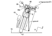
図5は、自動二輪車10が傾斜角αの登坂路74を走行している状態を側面から見たときの模式側面図であり、図6は、図5に示す自動二輪車10を拡大して正面から見たときの模式正面図である。尚、図5,6においては、理解の便宜のため、加速度センサ60を拡大(誇張)して模式的に表した。
FIG. 5 is a schematic side view of a state in which the
図5,6に示すように、加速度センサ60は、縦置きに配置されると共に、加速度センサの取り付け面60eに直交する方向に作用する加速度を示す出力xと、加速度センサ60の車長方向に作用する加速度を示す出力yを生じる。尚、図示の如く、加速度センサ60の取り付け面60eに直交する方向をX軸とし、加速度センサ60の車長方向をY軸、加速度センサ60の車幅方向をZ軸とする。
As shown in FIGS. 5 and 6, the
ECU34は、上記のようにして加速度センサ60から出力された出力x,yを検出し(S12)、その出力x,yと基準gとに基づいて登坂路74の傾斜角α、換言すれば、加速度センサ60の車長方向における傾斜角αを算出する(S14)。
The
具体的に説明すると、前記した出力x,yは、図5から分かるように、基準gと傾斜角αによって以下に示す式(1)(2)の如く表すことができる。
出力x=gcosαcosθ ・・・式(1)
出力y=gsinα ・・・式(2)
ここで、θは「加速度センサの車幅方向における傾斜角」、別言すれば、「車両の車幅方向における傾斜角」であり、自動二輪車10が車幅方向に傾斜していないときはθ=0[°](即ち、cosθ=1)となる。この車幅方向の傾斜角θについては後述する。
More specifically, as can be seen from FIG. 5, the outputs x and y can be expressed by the following equations (1) and (2) based on the reference g and the inclination angle α.
Output x = g cos α cos θ Expression (1)
Output y = g sin α (2)
Here, θ is “an inclination angle of the acceleration sensor in the vehicle width direction”, in other words, “an inclination angle of the vehicle in the vehicle width direction”. When the
従って、加速度センサ60の車長方向における傾斜角αは、上記した式(2)から導き出される式(3)によって算出することができる。
α=sin−1(y/g) ・・・式(3)
Therefore, the inclination angle α of the
α = sin −1 (y / g) (3)
このように、ECU34は、加速度センサ60の出力y(検出された加速度)と基準g(重力加速度)に基づいて加速度センサ60の車長方向における傾斜角αを算出する。
Thus, the
図4の説明に戻ると、次いでS16に進み、検出された加速度センサ60の出力x,yと、S14で算出された加速度センサ60の車長方向の傾斜角αとに基づいて加速度センサ60の車幅方向(左右軸方向)における(対する)傾斜角θを算出する。このS16の処理について、図7を参照して説明する。
Returning to the description of FIG. 4, the process then proceeds to S16, where the
図7は、図6に示す自動二輪車10が車幅方向に傾斜角θだけ傾斜した状態を表す模式正面図である。
FIG. 7 is a schematic front view showing a state in which the
図7から分かるように、加速度センサ60の出力xは、基準g、加速度センサ60の車長方向の傾斜角αおよび車幅方向の傾斜角θによって、前記した式(1)の如く表すことができる。従って、車両の車幅方向の傾斜角θは、式(1)から導き出される下記の式(4)によって算出することができる(S16)。
θ=cos−1(x/gcosα)
=cos−1[x/gcos(sin−1(y/g))] ・・・式(4)
As can be seen from FIG. 7, the output x of the
θ = cos −1 (x / g cos α)
= Cos −1 [x / g cos (sin −1 (y / g))] (4)
即ち、ECU34は、加速度センサの出力xと、S14で算出された加速度センサ60の車長方向の傾斜角αに基づいて加速度センサ60の車幅方向における傾斜角θを算出する。このように、「x=gcosθ」の右辺に「cosα」が乗算された式(1)から導き出される式(4)によって傾斜角θを算出する、換言すれば、加速度センサ60の車長方向の傾斜角αに基づき、加速度センサ60の出力x(検出された加速度)と基準g(重力加速度)に基づいて算出された加速度センサ60の車幅方向における傾斜角θを算出(補正)するようにした。
That is, the
図4の説明に戻ると、次いでS18に進み、S16で算出された加速度センサ60の車幅方向における傾斜角θと、加速度センサ60から出力された、正確には、加速度センサ60のメモリ60bから出力処理回路60c、A/D変換回路60dを介して出力された転倒しきい値(所定値)θ0とを比較する。具体的には、車両の車幅方向の傾斜角θが転倒しきい値θ0より大きいか否か判断する。尚、転倒しきい値θ0は、車両が転倒していると判断できる角度(例えば50[°])に設定される。
Returning to the description of FIG. 4, the process then proceeds to S <b> 18, and the inclination angle θ of the
S18で否定、即ち、車両が転倒していないと判断されるときは、S20に進み、後述するタイマカウンタTをリセットすると共に、S22に進み、通常の制御を実行、具体的には、入力されたセンサ出力などをパラメータとして演算を行い、自動二輪車10の運転状態に応じた制御信号を、燃料ポンプ40、インジェクタ44および点火コイル42などに出力する。
If it is negative in S18, that is, if it is determined that the vehicle has not fallen, the process proceeds to S20, a timer counter T described later is reset, and the process proceeds to S22, in which normal control is executed, specifically input. The calculation is performed using the sensor output as a parameter, and a control signal corresponding to the operating state of the
一方、S18で肯定されるとき、即ち、加速度センサ60の車幅方向の傾斜角θが転倒しきい値θ0を超え、車両が車幅方向に転倒した状態にあると判断されるときは、S24に進んでタイマカウンタTを1つインクリメントする。
On the other hand, when the result is affirmative at S18, i.e., when the inclination angle of the vehicle width direction of the
次いでS26に進み、タイマカウンタTの値が所定時間T0に(例えば2[sec])に達したか否か判断、即ち、タイマカウンタTをみることで、加速度センサ60の車幅方向の傾斜角θが転倒しきい値θ0を超えた状態が所定時間T0継続しているか否か判断し、否定されるときは前記したS22の処理を実行する一方、肯定されるときはS28に進み、エンジン20を停止させる処理を実行する。具体的には、燃料ポンプ40、インジェクタ44、および点火コイル42の動作を停止させる制御信号を出力する。これによりエンジン20の駆動は停止させられ、エンジン回転数Neは徐々に低下する。
Next, in S26, the value of the timer counter T is determined whether reached (e.g. 2 [sec]) in a predetermined time T 0, i.e., by looking at the timer counter T, the slope of the vehicle width direction of the
次いでS30に進み、クランク角センサ64などから検出されるエンジン回転数Neが0か否か判断する。S30で肯定されるとき、即ち、エンジン20の停止が確認されたときはS32に進み、S28で出力した燃料ポンプ40、インジェクタ44、および点火コイル42を停止させる制御信号の出力を解除する。尚、S30で否定されるときはS32の処理をスキップする。
Next, in S30, it is determined whether or not the engine speed Ne detected from the
このように、この実施例に係る鞍乗り型の車両の転倒検出装置にあっては、加速度センサ60で検出された加速度(具体的には、加速度センサ60の出力x,y)と基準g(鉛直下向き方向に作用する重力加速度)に基づいて加速度センサ60の車長方向における傾斜角αを算出し、算出された加速度センサ60の車長方向の傾斜角αに基づき、加速度センサ60の車幅方向の傾斜角θを補正するように構成、即ち、加速度センサ60の車長方向の傾斜角αを算出し、それに基づいて加速度センサ60の車幅方向の傾斜角θの算出(補正)および車両の車幅方向の転倒検出を行うように構成したので、加速度センサが所期の水平状態にない場合(例えば、登坂路74走行時などによって加速度センサ60が車長方向において傾斜した状態にある場合)であっても、加速度センサ60の車幅方向における傾斜角θを正確に算出(補正)でき、よって車両の車幅方向の転倒も正確に検出することができる。
As described above, in the saddle riding type vehicle overturn detection device according to this embodiment, the acceleration detected by the acceleration sensor 60 (specifically, the outputs x and y of the acceleration sensor 60) and the reference g ( The inclination angle α of the
また、加速度センサ60は、加速度センサの車長方向に作用する加速度(出力y)と、加速度センサの取り付け面に直交する方向に作用する加速度(出力x)とを検出するように構成すると共に、加速度センサの車長方向に作用する加速度(出力y)と基準gに基づいて加速度センサ60の車長方向の傾斜角αを算出すると共に、加速度センサの取り付け面60eに直交する方向に作用する加速度(出力x)と基準gに基づいて加速度センサ60の車幅方向の傾斜角θを算出し、算出された加速度センサ60の車長方向の傾斜角αに基づき、加速度センサ60の車幅方向の傾斜角θを補正するように構成したので、加速度センサ60の車幅方向の傾斜角θをより正確に算出(補正)できると共に、車両の車幅方向の転倒もより正確に検出することができる。
The
また、加速度センサ60は、車両に搭載されたエンジン20のスロットルボディ52に取り付けられるように構成したので、加速度センサ60の車幅方向の傾斜角θをより一層正確に算出でき、よって車両の車幅方向の転倒もより一層正確に検出することができる。
Further, since the
具体的には、エンジン20のスロットルボディ52は、図1,2に示すように、車両の重心付近に搭載されるため、加速度センサ60をスロットルボディ52に取り付けるように構成すると、加速度センサ60は、車両に作用する加速度(出力x,y)を正確に検出することが可能となり、それによって加速度センサ60の車幅方向の傾斜角θをより一層正確に算出できると共に、車両の車幅方向の転倒もより一層正確に検出することができる。
Specifically, as shown in FIGS. 1 and 2, the
また、スロットルボディは車種によってその取付角、具体的には、車長方向における取り付け角度が相違するが、この実施例にあっては、加速度センサ60をスロットルボディ52に取り付け、加速度センサ60で検出された加速度(出力x,y)に基づいて加速度センサ60の車長方向における傾斜角αを算出し、その車長方向の傾斜角αに基づいて加速度センサ60の車幅方向における傾斜角θを補正するように構成したので、どのような車種であっても、正確には、スロットルボディの車長方向における取り付け角度が水平でない車種であっても、共通の加速度センサを用いて加速度センサの車幅方向の傾斜角θを補正でき、車両の車幅方向の転倒を検出することができる。
The throttle body has a different mounting angle depending on the vehicle type, specifically, the mounting angle in the vehicle length direction. In this embodiment, the
また、加速度センサ60は、複数方向(具体的には2軸方向(より具体的には、加速度センサ60の車長方向(Y軸)と、加速度センサ60の取り付け面60eに直交する方向(X軸))の加速度を検出する加速度センサ素子60aと出力処理回路60cとを一体的に備えた半導体加速度センサからなるように構成したので、簡素な構成でありながら、上記した効果を得ることができる。
The
次いで、この発明の第2実施例に係る鞍乗り型の車両の転倒検出装置について説明する。 Next, a description will be given of a fall detection device for a saddle-ride type vehicle according to a second embodiment of the present invention.
図8は、第2実施例に係る鞍乗り型の車両の転倒検出装置の動作を部分的に示す、図4フローチャートの一部と同様のフローチャートである。 FIG. 8 is a flowchart similar to a part of the flowchart of FIG. 4 partially showing the operation of the overturn detection device for a saddle-ride type vehicle according to the second embodiment.
以下、第1実施例と相違する点に焦点をおいて説明すると、第2実施例にあっては、S12の後、S14aに進み、検出された加速度センサ60の出力x,yと基準gに基づいて加速度センサ60の車長方向における傾斜角βを算出する。この処理について、図9などを参照して説明する。
The following description focuses on the differences from the first embodiment. In the second embodiment, after S12, the process proceeds to S14a, and the detected output x, y of the
図9は、加速度センサ60が取り付け角度(取付角)βで取り付けられた自動二輪車10が走行している状態を示す、図5と同様な模式側面図である。尚、図9においては、理解の便宜のため、加速度センサ60を拡大(誇張)して模式的に表した。
FIG. 9 is a schematic side view similar to FIG. 5 showing a state in which the
ECU34は、S12で検出された加速度センサ60の出力x,yと基準gとに基づいて加速度センサ60が取付角β、換言すれば、加速度センサ60の車長方向における傾斜角βを算出する(S14a)。
The
具体的に説明すると、前記した出力x,yは、図9から分かるように、基準gと取付角βによって以下に示す式(5)(6)の如く表すことができる。
出力x=gcosβcosθ ・・・式(5)
出力y=gsinβ ・・・式(6)
More specifically, as can be seen from FIG. 9, the outputs x and y can be expressed by the following equations (5) and (6) based on the reference g and the mounting angle β.
Output x = g cos β cos θ Expression (5)
Output y = g sin β Equation (6)
従って、加速度センサ60の取付角β(即ち、加速度センサ60の車長方向における傾斜角β)は、上記した式(6)から導き出される式(7)によって算出することができる。
β=sin−1(y/g) ・・・式(7)
Therefore, the mounting angle β of the acceleration sensor 60 (that is, the inclination angle β in the vehicle length direction of the acceleration sensor 60) can be calculated by the equation (7) derived from the above equation (6).
β = sin −1 (y / g) (7)
このように、ECU34は、加速度センサ60の出力y(検出された加速度)と基準g(重力加速度)に基づいて加速度センサ60の取付角β(加速度センサ60の車長方向における傾斜角β)を算出する。
Thus, the
図8の説明に戻ると、次いでS16aに進み、検出された加速度センサ60の出力x,yと、S14aで算出された加速度センサ60の車長方向の傾斜角βとに基づいて加速度センサ60の車幅方向における傾斜角θを算出する。このS16aの処理について、図6,7を参照して説明する。尚、図6,7において、第2実施例に該当する値は大カッコを付して示した。
Returning to the description of FIG. 8, the process then proceeds to S16a, where the
図6,7から分かるように、加速度センサ60の出力xは、基準g、加速度センサ60の車長方向の傾斜角βおよび車幅方向の傾斜角θによって、前記した式(5)の如く表すことができる。従って、車両の車幅方向の傾斜角θは、式(5)から導き出される下記の式(8)によって算出することができる(S16a)。
θ=cos−1(x/gcosβ)
=cos−1[x/gcos(sin−1(y/g))] ・・・式(8)
As can be seen from FIGS. 6 and 7, the output x of the
θ = cos −1 (x / g cos β)
= Cos −1 [x / g cos (sin −1 (y / g))] (8)
即ち、ECU34は、加速度センサの出力xと、S14aで算出された加速度センサ60の車長方向の取付角(傾斜角)βに基づいて加速度センサ60の車幅方向における傾斜角θを算出する。このように、「x=gcosθ」の右辺に「cosβ」が乗算された式(5)から導き出される式(8)によって傾斜角θを算出する、換言すれば、加速度センサ60の車長方向の取付角(傾斜角)βに基づき、加速度センサ60の出力x(検出された加速度)と基準g(重力加速度)に基づいて算出された加速度センサ60の車幅方向における傾斜角θを算出(補正)するようにした。
That is, the
第2実施例にあっては上記の如く構成したので、加速度センサ60が所期の水平状態にない場合(具体的には、加速度センサ60が水平に取り付けられていない場合)であっても、加速度センサ60の車幅方向における傾斜角θを正確に算出(補正)でき、よって車両の車幅方向の転倒も正確に検出することができる。
Since the second embodiment is configured as described above, even when the
また、上記において、加速度センサ60が所期の水平状態にない場合として、加速度センサ60が水平に取り付けられていない状態を例にとって説明したが、2人乗りや荷物の積載などによって加速度センサ60が車長方向において傾斜した状態にある場合であっても、上記の如く構成することで、同様の効果を得ることができる。
In the above description, the case where the
尚、残余の構成および効果は、第1実施例のそれと異ならない。 The remaining configuration and effects are not different from those of the first embodiment.
以上の如く、この発明の第1および第2実施例にあっては、鞍乗り型の車両に(自動二輪車10)作用する加速度を検出する加速度センサ60、前記検出された加速度(出力x,y)と重力加速度(鉛直下向き方向に作用する重力加速度。基準g)に基づいて前記加速度センサの車幅方向における傾斜角を示す値(傾斜角θ)を算出する車幅方向傾斜角算出手段(ECU34。S16、S16a)、および前記算出された加速度センサの車幅方向の傾斜角を示す値と所定値(転倒しきい値θ0)とを比較して前記車両の車幅方向の転倒を検出する転倒検出手段(ECU34。S18からS26)を備えた鞍乗り型の車両の転倒検出装置において、前記検出された加速度と前記重力加速度に基づいて前記加速度センサの車長方向における傾斜角を示す値(傾斜角α(β))を算出する車長方向傾斜角算出手段(ECU34。S14、S14a)、および前記算出された加速度センサの車長方向の傾斜角を示す値に基づき、前記算出された加速度センサの車幅方向の傾斜角を示す値を補正する補正手段(ECU34。S16、S16a)を備えるように構成した。
As described above, in the first and second embodiments of the present invention, the
また、前記加速度センサ60は、前記加速度センサの車長方向に作用する加速度(出力y)と、前記加速度センサの取り付け面60eに直交する方向に作用する加速度(出力x)とを検出するように構成した。
The
また、前記加速度センサ60は、前記車両に搭載された内燃機関(エンジン20)のスロットルボディ52に取り付けられるように構成した。
The
また、前記加速度センサ60は、複数方向の加速度を検出する加速度センサ素子60aと出力処理回路60cとを一体的に備えた半導体加速度センサからなるように構成した。
The
尚、上記において、加速度センサ60を縦置きに配置するように構成したが、図10および図11に示す如く、加速度センサ60を横置きに配置し、加速度センサの車長方向(Y軸)に作用する加速度と、加速度センサの車幅方向(Z軸)に作用する加速度を示す出力を生じるように構成してもよい。この場合、式(1)〜(8)における「cosθ」「アークコサイン(cos−1)」「x」を、それぞれ「sinθ」「アークサイン(sin−1)」「z」と変更するだけでよく、残余の構成は第1,2実施例のそれと異ならない。
In the above description, the
また、加速度センサ60の車長方向の傾斜角α(β)を算出した後、算出した傾斜角α(β)に基づいて加速度センサ60の車幅方向の傾斜角θを補正(算出)するように構成したが、それに限られるものではなく、傾斜角α(β)に基づいて前記した転倒しきい値θ0を適宜に補正するように構成してもよい。
Further, after calculating the inclination angle α (β) of the
また、加速度センサ60の車長方向の傾斜角α(β)を算出した後、算出した傾斜角α(β)に基づいて加速度センサ60の車幅方向の傾斜角θを算出するように構成したが、式(4),(8)から分かるように、傾斜角α(β)を算出せず、加速度センサ60の出力x,y、基準gから傾斜角θを算出するようにしてもよい。その意味から、特許請求の範囲では「加速度センサの車長方向の傾斜角を示す値」と記載した。
Further, after calculating the inclination angle α (β) of the
また、鞍乗り型の車両を例にとって説明したが、それに限られるものではなく、他の車両であってもよい。 Further, although a saddle-ride type vehicle has been described as an example, the present invention is not limited thereto, and other vehicles may be used.
10 自動二輪車(鞍乗り型の車両)、20 エンジン(内燃機関)、34 ECU(車幅方向傾斜角算出手段、転倒検出手段、車長方向傾斜角算出手段、補正手段)、52 スロットルボディ、60 加速度センサ、60a 加速度センサ素子、60c 出力処理回路、60e (加速度センサの)取り付け面 10 motorcycle (saddle-ride type vehicle), 20 engine (internal combustion engine), 34 ECU (vehicle width direction inclination angle calculation means, fall detection means, vehicle length direction inclination angle calculation means, correction means), 52 throttle body, 60 Acceleration sensor, 60a acceleration sensor element, 60c output processing circuit, 60e (acceleration sensor) mounting surface
Claims (4)
a.前記検出された加速度と前記重力加速度に基づいて前記加速度センサの車長方向における傾斜角を示す値を算出する車長方向傾斜角算出手段、
および
b.前記算出された加速度センサの車長方向の傾斜角を示す値に基づき、前記算出された加速度センサの車幅方向の傾斜角を示す値を補正する補正手段、
を備えることを特徴とする鞍乗り型の車両の転倒検出装置。 An acceleration sensor that detects acceleration acting on the saddle-ride type vehicle, vehicle width direction inclination angle calculation means that calculates a value indicating an inclination angle of the acceleration sensor in the vehicle width direction based on the detected acceleration and gravitational acceleration; Further, the fall detection of the saddle-ride type vehicle provided with the fall detection means for detecting the fall of the vehicle width direction of the vehicle by comparing the calculated value indicating the inclination angle of the acceleration sensor in the vehicle width direction with a predetermined value. In the device
a. Vehicle length direction inclination angle calculating means for calculating a value indicating an inclination angle of the acceleration sensor in the vehicle length direction based on the detected acceleration and the gravitational acceleration;
And b. Correction means for correcting the calculated value indicating the inclination angle of the acceleration sensor in the vehicle width direction based on the calculated value indicating the inclination angle of the acceleration sensor in the vehicle length direction;
A fall detection device for a saddle-ride type vehicle, comprising:
Priority Applications (1)
| Application Number | Priority Date | Filing Date | Title |
|---|---|---|---|
| JP2006262601A JP2008082855A (en) | 2006-09-27 | 2006-09-27 | Fall detection device for saddle riding type vehicles |
Applications Claiming Priority (1)
| Application Number | Priority Date | Filing Date | Title |
|---|---|---|---|
| JP2006262601A JP2008082855A (en) | 2006-09-27 | 2006-09-27 | Fall detection device for saddle riding type vehicles |
Publications (1)
| Publication Number | Publication Date |
|---|---|
| JP2008082855A true JP2008082855A (en) | 2008-04-10 |
Family
ID=39353878
Family Applications (1)
| Application Number | Title | Priority Date | Filing Date |
|---|---|---|---|
| JP2006262601A Pending JP2008082855A (en) | 2006-09-27 | 2006-09-27 | Fall detection device for saddle riding type vehicles |
Country Status (1)
| Country | Link |
|---|---|
| JP (1) | JP2008082855A (en) |
Cited By (3)
| Publication number | Priority date | Publication date | Assignee | Title |
|---|---|---|---|---|
| JP2009264771A (en) * | 2008-04-22 | 2009-11-12 | Asahi Denso Co Ltd | Vehicle inclination sensor |
| JP2010286278A (en) * | 2009-06-09 | 2010-12-24 | Mitsubishi Electric Corp | Device, method, and program for processing data |
| JP2011185107A (en) * | 2010-03-05 | 2011-09-22 | Kokusan Denki Co Ltd | Engine control device for motorcycle |
Citations (5)
| Publication number | Priority date | Publication date | Assignee | Title |
|---|---|---|---|---|
| JPH10267651A (en) * | 1997-03-28 | 1998-10-09 | Data Tec:Kk | Method and instrument for measuring inclination |
| JPH11230742A (en) * | 1998-02-09 | 1999-08-27 | Nippon Soken Inc | Road shape measurement device |
| JP2004093537A (en) * | 2001-10-19 | 2004-03-25 | Yamaha Motor Co Ltd | Fall down detection device of motorcycle |
| JP2006224964A (en) * | 2006-03-27 | 2006-08-31 | Keihin Corp | Two-wheeled vehicle fall detection device |
| JP2008080955A (en) * | 2006-09-27 | 2008-04-10 | Yamaha Motor Co Ltd | Vehicle fall detection device and saddle riding type vehicle equipped with the fall detection device |
-
2006
- 2006-09-27 JP JP2006262601A patent/JP2008082855A/en active Pending
Patent Citations (5)
| Publication number | Priority date | Publication date | Assignee | Title |
|---|---|---|---|---|
| JPH10267651A (en) * | 1997-03-28 | 1998-10-09 | Data Tec:Kk | Method and instrument for measuring inclination |
| JPH11230742A (en) * | 1998-02-09 | 1999-08-27 | Nippon Soken Inc | Road shape measurement device |
| JP2004093537A (en) * | 2001-10-19 | 2004-03-25 | Yamaha Motor Co Ltd | Fall down detection device of motorcycle |
| JP2006224964A (en) * | 2006-03-27 | 2006-08-31 | Keihin Corp | Two-wheeled vehicle fall detection device |
| JP2008080955A (en) * | 2006-09-27 | 2008-04-10 | Yamaha Motor Co Ltd | Vehicle fall detection device and saddle riding type vehicle equipped with the fall detection device |
Cited By (3)
| Publication number | Priority date | Publication date | Assignee | Title |
|---|---|---|---|---|
| JP2009264771A (en) * | 2008-04-22 | 2009-11-12 | Asahi Denso Co Ltd | Vehicle inclination sensor |
| JP2010286278A (en) * | 2009-06-09 | 2010-12-24 | Mitsubishi Electric Corp | Device, method, and program for processing data |
| JP2011185107A (en) * | 2010-03-05 | 2011-09-22 | Kokusan Denki Co Ltd | Engine control device for motorcycle |
Similar Documents
| Publication | Publication Date | Title |
|---|---|---|
| US6941206B2 (en) | Tip-over detection device for motor vehicle | |
| US8352122B2 (en) | Engine control apparatus and straddle-type vehicle | |
| US20020039951A1 (en) | Acceleration sensor and engine control for motorcycle | |
| JP4290950B2 (en) | Overturn detection device for motorcycles | |
| JP6613092B2 (en) | Saddle riding vehicle | |
| EP3165738B1 (en) | Straddled vehicle with single-cylinder four-stroke engine unit | |
| JP2006307782A (en) | Control device for vehicle engine, control method and its program | |
| JP2008082855A (en) | Fall detection device for saddle riding type vehicles | |
| JP2007092747A (en) | Engine control apparatus for motorcycle and motorcycle | |
| US9309827B2 (en) | Fuel injection control device for saddle-ride type vehicle | |
| EP2530288B1 (en) | Activation determining system for oxygen sensor | |
| JP5175166B2 (en) | Alternative fuel concentration estimation device and alternative fuel concentration estimation method | |
| EP3252288A1 (en) | Engine unit | |
| JP4912102B2 (en) | Vehicle fall detection device and saddle riding type vehicle equipped with the fall detection device | |
| CN103133212B (en) | Saddle-ride type vehicle | |
| JP5010893B2 (en) | Vehicle state detection device | |
| US20060025916A1 (en) | Vehicle control system having atmospheric pressure estimating function | |
| EP3239504B1 (en) | Engine unit | |
| JP5010892B2 (en) | Vehicle fall detection device | |
| CN1796961A (en) | Detection device and method for engine misfiring, cross-ride vehicle | |
| WO2021206091A1 (en) | Vehicle | |
| WO2021181599A1 (en) | Saddle-riding-type vehicle | |
| JPH10184436A (en) | Fuel property detector of internal combustion engine | |
| EP2894320A1 (en) | An apparatus for detecting unstable combustion in an internal combustion engine | |
| JP2010216342A (en) | Control device for internal combustion engine |
Legal Events
| Date | Code | Title | Description |
|---|---|---|---|
| A621 | Written request for application examination |
Free format text: JAPANESE INTERMEDIATE CODE: A621 Effective date: 20090824 |
|
| A977 | Report on retrieval |
Free format text: JAPANESE INTERMEDIATE CODE: A971007 Effective date: 20111125 |
|
| A131 | Notification of reasons for refusal |
Effective date: 20111220 Free format text: JAPANESE INTERMEDIATE CODE: A131 |
|
| A521 | Written amendment |
Free format text: JAPANESE INTERMEDIATE CODE: A523 Effective date: 20120216 |
|
| A131 | Notification of reasons for refusal |
Effective date: 20120307 Free format text: JAPANESE INTERMEDIATE CODE: A131 |
|
| A521 | Written amendment |
Effective date: 20120427 Free format text: JAPANESE INTERMEDIATE CODE: A523 |
|
| A02 | Decision of refusal |
Free format text: JAPANESE INTERMEDIATE CODE: A02 Effective date: 20120613 |