JP2008062369A - Method of producing tip to be mounted on boring tool, method of producing boring tool, and boring tool - Google Patents
Method of producing tip to be mounted on boring tool, method of producing boring tool, and boring tool Download PDFInfo
- Publication number
- JP2008062369A JP2008062369A JP2006245579A JP2006245579A JP2008062369A JP 2008062369 A JP2008062369 A JP 2008062369A JP 2006245579 A JP2006245579 A JP 2006245579A JP 2006245579 A JP2006245579 A JP 2006245579A JP 2008062369 A JP2008062369 A JP 2008062369A
- Authority
- JP
- Japan
- Prior art keywords
- chip
- tip
- drilling tool
- slit
- cutting edge
- Prior art date
- Legal status (The legal status is an assumption and is not a legal conclusion. Google has not performed a legal analysis and makes no representation as to the accuracy of the status listed.)
- Pending
Links
Images


Landscapes
- Drilling Tools (AREA)
- Electrical Discharge Machining, Electrochemical Machining, And Combined Machining (AREA)
- Finish Polishing, Edge Sharpening, And Grinding By Specific Grinding Devices (AREA)
Abstract
Description
本発明は、穴あけ工具に取り付けられるチップの製造方法、並びに穴あけ工具の製造方法および穴あけ工具に関し、特に、深穴加工等に好適に用いられるドリルに接合されて使用されるチップの製造方法、並びにドリルの製造方法およびドリルに関する。 TECHNICAL FIELD The present invention relates to a method for manufacturing a tip attached to a drilling tool, a method for manufacturing a drilling tool, and a drilling tool, and in particular, a method for manufacturing a tip used by being joined to a drill suitably used for deep hole machining and the like, and The present invention relates to a drill manufacturing method and a drill.
穴あけ工具の刃部材料としては、超硬合金、サーメット、セラミックス等が一般的であるが、近年、より硬い材料をより早く加工したいというニーズから、極めて硬度の高いダイヤモンド焼結体や立方晶窒化ホウ素(cBN)焼結体が使用されるようになってきた。特に、アルミニウム合金や銅合金の加工においては、超硬工具では刃先に加工材料が溶着しやすく高精度の仕上げ面を得ることができないため、それらの加工材料と溶着しにくいダイヤモンド焼結体が適用されている。また、焼入鋼や鋳鉄等の仕上げ加工においては、ダイヤモンド焼結体より鉄と反応しにくく硬度が高い立方晶窒化ホウ素(cBN)焼結体が適用されている。
一方、アルミニウム合金、鋳鉄等を材料とする自動車のオートマティックトランスミッション部品であるコントロールバルブボディのスプール穴やエンジンなどの製造工程においては、異物の混入を回避する必要性および切りくず処理向上の観点から、穴あけ加工の際に生じる切りくずの細分化が強く要求されている。
この点、従来より、切りくずを分断するための手段としてドリル先端部の切れ刃の一部を切り欠いてニックを設けたニック付ドリルが知られている。このニック付ドリルは、通常、ニックが切れ刃から逃げ面に沿って設けられているため(図7参照)、ドリル先端部の切れ刃を再研磨する場合には再度ニックを研削加工しなければならず作業が煩雑であった。そこで、この問題を解決するために、ニックが切れ刃から溝面に沿って連続的に設けられているニック付ドリルが提案されている(例えば、特許文献1参照)。
On the other hand, in the manufacturing process of control valve body spool holes and engines, etc., which are automotive automatic transmission parts made of aluminum alloy, cast iron, etc., from the viewpoint of the need to avoid contamination and the improvement of chip disposal, There is a strong demand for fragmentation of chips generated during drilling.
In this respect, conventionally, a drill with a nick provided with a nick by cutting out a part of the cutting edge at the tip of the drill is known as means for dividing chips. In this drill with a nick, since the nick is usually provided along the flank from the cutting edge (see FIG. 7), the nick must be ground again when re-grinding the cutting edge at the tip of the drill. The work was complicated. In order to solve this problem, a drill with a nick in which a nick is continuously provided from the cutting edge along the groove surface has been proposed (for example, see Patent Document 1).
しかし、ダイヤモンド焼結体や立方晶窒化ホウ素(cBN)焼結体を刃部材料とする場合には、その硬度が非常に高いことから、ニックの研削加工には長時間を要し、また、通常の研削加工では微細な形状のニックを所定位置に正確に加工することは困難であるという問題があった。さらに、かかる場合ダイヤモンドホイール等の高価な砥石を使用しなければならないにもかかわらず、研削比が極端に低いので、被削材より砥石が削れられる状態になってしまう恐れもあり、砥石寿命が短くなってしまうという問題もあった。
また、上記特許文献1の発明では、刃部を含むボデーからシャンクまでの工具全体が同一材料からなるソリッドドリルであることから、ダイヤモンド焼結体や立方晶窒化ホウ素(cBN)焼結体により切れ刃を形成すると、材料費が非常に高いことから製造コストが高くなってしまうという問題があった。また、ニック溝が、切れ刃から切屑排出溝の溝面に沿って、切屑排出溝と平行に連続して延びるように設けられることから、ニック溝を加工するのに長時間を要し製造効率が極めて悪いという問題があった。
However, when a diamond sintered body or a cubic boron nitride (cBN) sintered body is used as the blade material, the hardness is very high, so a long time is required for nick grinding, In normal grinding, there is a problem that it is difficult to accurately process a nick having a fine shape at a predetermined position. Furthermore, in such a case, although an expensive grindstone such as a diamond wheel must be used, the grinding ratio is extremely low, so there is a possibility that the grindstone may be scraped off from the work material, and the grindstone life is shortened. There was also a problem of shortening.
In the invention of Patent Document 1, since the entire tool from the body to the shank including the blade portion is a solid drill made of the same material, it is cut by a diamond sintered body or a cubic boron nitride (cBN) sintered body. When the blade is formed, there is a problem that the manufacturing cost becomes high because the material cost is very high. Also, since the nick groove is provided so as to extend continuously from the cutting edge along the groove surface of the chip discharge groove in parallel with the chip discharge groove, it takes a long time to process the nick groove, and the production efficiency There was a problem that was very bad.
本発明は、上記問題を解決するためになされたもので、切りくず処理性および加工穴の加工精度に優れ、短時間かつ低コストで製造することができ、切れ刃を再研磨する度にニックを研削加工する必要のない、工具寿命に優れた穴あけ工具を提供することを課題とする。 The present invention has been made in order to solve the above-mentioned problems, and is excellent in chip disposal and machining accuracy of a machined hole, can be manufactured in a short time and at a low cost, and is nicked each time the cutting edge is re-polished. It is an object of the present invention to provide a drilling tool that does not require grinding and has an excellent tool life.
上記課題を解決するために、本発明は以下の手段を採用する。
請求項1に記載の発明は、略平板状をなし、この上面に設けられたすくい面と、このすくい面と交差する側面に設けられた逃げ面と、これらすくい面と逃げ面との交差稜線部に設けられた切れ刃部とを有し、この切れ刃部がダイヤモンド焼結体、立方晶窒化ホウ素焼結体等の超高圧焼結体から形成された、穴あけ工具に取り付けられるチップの製造方法であって、この穴あけ工具に取り付ける前におけるチップの切れ刃部の一部を、ワイヤカット、レーザー加工、電子ビーム加工等の放電加工により、切れ刃部からすくい面方向に向かって切り欠いて、チップの厚さ方向に貫通しつつすくい面方向に伸びるスリットを形成する工程を備えることを特徴とする。
In order to solve the above problems, the present invention employs the following means.
The invention according to claim 1 has a substantially flat plate shape, a rake face provided on the upper surface, a flank face provided on a side surface intersecting with the rake face, and an intersecting ridge line between the rake face and the flank face. Of a chip attached to a drilling tool having a cutting edge portion provided on the portion and formed from an ultra-high pressure sintered body such as a diamond sintered body or a cubic boron nitride sintered body. A part of the cutting edge portion of the chip before being attached to the drilling tool is cut out from the cutting edge portion toward the rake face by electric discharge machining such as wire cutting, laser processing, or electron beam machining. And a step of forming a slit extending in the rake face direction while penetrating in the thickness direction of the chip.
本発明によれば、硬度の極めて高い被削材も加工することができ複雑、微細な形状の加工も容易に行うことができる放電加工によって切れ刃部にスリットを形成することから、従来の研削加工ではできないような複雑、微細な形状のスリットを形成することが可能であり、切れ刃部が超高圧焼結体から形成されたものであっても、スリットの幅、長さ、位置などを自由に設定することができ、切りくず分断のためのスリットを短時間で能率よく形成することができる。 According to the present invention, since the work material with extremely high hardness can be processed and the slit is formed in the cutting edge portion by electric discharge machining which can easily process a complicated and fine shape, conventional grinding is performed. It is possible to form slits with complicated and fine shapes that cannot be processed, and the width, length, position, etc. of the slits can be adjusted even if the cutting edge is made of an ultra-high pressure sintered body. It can be set freely, and slits for cutting chips can be efficiently formed in a short time.
請求項2に記載の発明は、請求項1に記載の穴あけ工具に取り付けられるチップの製造方法により製造された穴あけ工具に取り付けられるチップを、穴あけ工具本体の先端部に形成されたチップ取付座に載置し、スリットが工具先端側から後端側に向かって伸びるように配置する工程と、チップ取付座に前記穴あけ工具に取り付けられるチップを接合する工程と、この接合された穴あけ工具に取り付けられるチップの前記切れ刃部を研磨して切れ刃を形成する工程を備えることを特徴とする。 According to a second aspect of the present invention, a tip attached to a drilling tool manufactured by the manufacturing method of a tip attached to the drilling tool according to the first aspect is attached to a tip mounting seat formed at the tip of the drilling tool main body. Placing the slit so that the slit extends from the front end side to the rear end side of the tool, joining the tip attached to the drilling tool to the tip mounting seat, and attaching to the joined drilling tool A step of polishing the cutting edge portion of the chip to form a cutting edge is provided.
本発明によれば、チップ取付座に接合する前におけるチップの切れ刃部にあらかじめスリットを形成することから、切りくず分断のためのスリットを所望の位置および形状に、正確かつ容易に形成することができる。そして、チップ取付座に接合する前におけるチップの切れ刃部に、あらかじめワイヤカット、レーザー加工、電子ビーム加工等の放電加工によりスリットを形成することから、製造工程が簡略化され製造効率の向上および製造コストの縮減を図ることができる。また、このスリットを工具先端側から後端側に向かってすくい面に沿って伸びるように配置してチップを接合することから、切削を行った後に切れ刃を再研磨する場合であっても改めてスリットを加工形成する必要がないので、この製造方法によればスリットを所望の位置および形状に安定させることができる。 According to the present invention, since the slit is formed in advance in the cutting edge portion of the chip before joining to the chip mounting seat, it is possible to accurately and easily form the slit for chip separation at a desired position and shape. Can do. And since the slit is formed in advance by electric discharge machining such as wire cutting, laser machining, electron beam machining, etc. in the cutting edge portion of the chip before joining to the chip mounting seat, the production process is simplified and the production efficiency is improved. The manufacturing cost can be reduced. In addition, since the slit is arranged so as to extend along the rake face from the tool front end side to the rear end side, the chip is joined, so even if the cutting edge is re-polished after cutting, Since it is not necessary to process and form the slit, this manufacturing method can stabilize the slit at a desired position and shape.
請求項3に記載の発明は、請求項2に記載の穴あけ工具の製造方法により製造されたことを特徴とする。 The invention according to claim 3 is manufactured by the method for manufacturing a drilling tool according to claim 2.
本発明によれば、切れ刃部の一部を切れ刃部からすくい面方向に向かって切り欠いて、チップの厚さ方向に貫通するとともにすくい面方向に伸びるスリットが形成されていることから、スリット箇所における切れ刃がスリットの深さ即ちチップの厚さの分だけ後退する。この切れ刃の逃げ角方向から見た後退量が切取り厚さよりも大きいと、そのスリット箇所は切削に関与しないことから、切りくずが分断されることになる。ここで、この穴あけ工具には、通常2枚のチップが互いの切れ刃部が工具回転軸の対称位置となるように取り付けられる。そして、これらの切れ刃部の夫々に1以上形成された各スリットは、チップ取付状態において回転軸に対して非対称になるように互いに半径方向にずらして配置されるとともに、それらの回転軌跡がそれぞれ異なるように構成される。よって、このスリット箇所での削り残し部分は、半回転後に反対側にある切れ刃によって1枚刃で切削されることになる。 According to the present invention, a part of the cutting edge portion is cut out from the cutting edge portion toward the rake face direction, and a slit is formed that extends in the rake face direction while penetrating in the thickness direction of the chip. The cutting edge at the slit is retracted by the depth of the slit, that is, the thickness of the chip. If the amount of retraction viewed from the clearance angle direction of the cutting edge is larger than the cut-off thickness, the slit portion is not involved in cutting, so that the chips are divided. Here, normally, two chips are attached to the drilling tool such that the cutting edge portions of the two chips are symmetrical with respect to the tool rotation axis. The slits formed in one or more of each of these cutting edge portions are arranged so as to be shifted from each other in the radial direction so as to be asymmetric with respect to the rotation axis in the chip mounting state. Configured differently. Therefore, the uncut portion at the slit portion is cut with a single blade by the cutting blade on the opposite side after half rotation.
このような切りくずの分断により、穴あけ深さが増しても切りくずを容易に排出することができ、幅が狭い切りくずは容易に弾性変形するので、切りくずによる引っかき傷やむしれ跡が残りにくく、穴内面の粗さやうねり等の仕上げ面の品位に優れる。また、穴あけ深さが増しても切りくず詰まりを起こすことがないので切削抵抗やトルクが増大、変動することがないため、穴出口側に発生するバリの抑制を図ることができるとともに、切れ刃の摩耗や欠損が少なく、工具寿命に優れる。さらに、被削材の加工部分が狭い場合であっても、切りくずの微細化により被削材への切りくず残留を防止することができるので、穴あけ加工後にエアー等で切りくずを洗浄する必要が生じて作業が煩雑になるという問題もない。 By dividing the chip like this, the chip can be easily discharged even if the drilling depth is increased, and the chip having a narrow width is easily elastically deformed, so that scratches and scratch marks caused by the chip are hardly left. Excellent finish surface quality such as roughness and undulation of the inner surface of the hole. In addition, since chip clogging does not occur even when the drilling depth is increased, cutting resistance and torque do not increase or fluctuate, so that burr generated on the hole exit side can be suppressed and the cutting edge can be reduced. There is little wear and damage, and the tool life is excellent. Furthermore, even if the work part of the work material is narrow, it is possible to prevent chips from remaining on the work material by making the chips finer, so it is necessary to clean the chips with air after drilling. There is no problem that the work becomes complicated due to the occurrence of the problem.
また、このスリットは工具先端側から後端側に向かってすくい面に沿って伸びるように形成されることから、切削を行った後に切れ刃を再研磨する場合であっても、改めてスリットを加工形成することなく新品時と同様の性能を得ることができるので、作業効率に優れる。そして、切れ刃を再研磨する度にスリットを再成形する必要がないため、スリットの位置および形状を常に安定させることができる。 In addition, this slit is formed so as to extend along the rake face from the tool front end side to the rear end side, so that even when the cutting edge is repolished after cutting, the slit is processed again. Since it is possible to obtain the same performance as when it is new without being formed, the working efficiency is excellent. And since it is not necessary to reshape the slit every time the cutting edge is repolished, the position and shape of the slit can be always stabilized.
さらに、切れ刃部が超高圧焼結体から形成されることから、耐摩耗性が高く、極めて優れた工具寿命を得ることができる。特に、切れ刃部がアルミニウム合金や銅合金と溶着しにくいダイヤモンド焼結体から形成される場合には、これらを被削材とする穴あけ加工において高精度の仕上げ面を得ることができる点で有用である。また、切れ刃部が鉄と反応しにくい立方晶窒化ホウ素(cBN)焼結体から形成される場合には、焼入鋼や鋳鉄等の仕上げ加工において高精度の仕上げ面を得ることができる点で有用である。また、チップを切れ刃として工具本体に接合した穴あけ工具であることから、ソリッドドリルに比べ製造コストが低く、切れ刃が超高圧焼結体からなる穴あけ工具を安価に提供することができる。 Furthermore, since the cutting edge portion is formed from an ultra-high pressure sintered body, the wear resistance is high, and an extremely excellent tool life can be obtained. In particular, when the cutting edge is formed from a diamond sintered body that is difficult to weld with an aluminum alloy or a copper alloy, it is useful in that a highly accurate finished surface can be obtained in drilling using these as a work material. It is. In addition, when the cutting edge portion is formed of a cubic boron nitride (cBN) sintered body that does not easily react with iron, a highly accurate finished surface can be obtained in finishing processing of hardened steel, cast iron, or the like. It is useful in. Moreover, since it is a drilling tool joined to the tool body as a cutting edge, the manufacturing cost is lower than that of a solid drill, and a drilling tool whose cutting edge is made of an ultra-high pressure sintered body can be provided at low cost.
請求項1の穴あけ工具に取り付けられるチップの製造方法によれば、切れ刃部が超高圧焼結体から形成されたものであっても、切れ刃部に従来の研削加工ではできないような複雑、微細な形状の切りくず分断のためのスリットを短時間で能率よく形成することができるという効果を奏する。 According to the manufacturing method of the chip attached to the drilling tool according to claim 1, even if the cutting edge portion is formed from an ultra-high pressure sintered body, the cutting edge portion cannot be complicated by conventional grinding, There is an effect that it is possible to efficiently form a slit for cutting a finely shaped chip in a short time.
請求項2の穴あけ工具の製造方法によれば、切りくず分断のためのスリットを所望の位置および形状に、正確かつ容易に形成することができ、製造効率の向上を図ることができるという効果を奏する。 According to the manufacturing method of the drilling tool of claim 2, it is possible to accurately and easily form the slit for cutting the chip in a desired position and shape, and to improve the manufacturing efficiency. Play.
請求項3の穴あけ工具によれば、切りくず処理性および加工穴の加工精度に優れ、短時間かつ低コストで製造することができ、切れ刃を再研磨する度に切りくずを分断するためのスリットを再度研削加工する必要のない、工具寿命に優れた穴あけ工具を提供できるという効果を奏する。 According to the drilling tool of claim 3, it is excellent in chip disposal and processing accuracy of the drilled hole, can be manufactured in a short time and at low cost, and the chip is divided every time the cutting edge is repolished. There is an effect that it is possible to provide a drilling tool having an excellent tool life without the need to grind the slit again.
以下、本発明の穴あけ工具に取り付けられるチップの製造方法および穴あけ工具の製造方法の一実施形態について、図面に基づいて説明する。
図1は、本発明の穴あけ工具に取り付けられるチップの製造方法により製造されたチップの一実施例に係るチップを示す斜視図である。そして、図2は、本発明の穴あけ工具の製造方法により製造された穴あけ工具の一実施例に係る図1のチップが接合されたドリルを示す正面図であり、図3はその左側面図、図5はその刃先部分の拡大図である。また、図4(a)は、図2に示すドリルのチップ取付前におけるチップ取付座の斜視図であり、図4(b)はそのチップ取付後におけるチップ取付座の斜視図である。さらに、図6は、本実施例に係るドリルの切りくず分断機構を説明する模式図である。
Hereinafter, an embodiment of a manufacturing method of a chip attached to a drilling tool of the present invention and a manufacturing method of a drilling tool will be described based on the drawings.
FIG. 1 is a perspective view showing a chip according to an embodiment of a chip manufactured by a method of manufacturing a chip attached to a drilling tool of the present invention. FIG. 2 is a front view showing a drill to which the tip of FIG. 1 according to one embodiment of a drilling tool manufactured by the manufacturing method of the drilling tool of the present invention is joined, and FIG. 3 is a left side view thereof. FIG. 5 is an enlarged view of the cutting edge portion. 4A is a perspective view of the tip mounting seat before the tip mounting of the drill shown in FIG. 2, and FIG. 4B is a perspective view of the tip mounting seat after the tip mounting. Furthermore, FIG. 6 is a schematic diagram for explaining the chip breaking mechanism of the drill according to the present embodiment.
本実施形態に係る穴あけ工具に取り付けられるチップおよび穴あけ工具の製造方法においては、先ず、ダイヤモンド焼結体、立方晶窒化ホウ素焼結体等の超高圧焼結体から形成された円盤状のブランクスを作製する。
そして、この円盤状のブランクスからワイヤカット、レーザー加工、電子ビーム加工等の放電加工により、略平板状に切り出し、その上面に設けられたすくい面11と、そのすくい面11と交差する側面に設けられた逃げ面12との交差稜線部に、切れ刃部15を有するチップを得る。
こうして得られたチップの切れ刃部15の一部を、ワイヤカット、レーザー加工、電子ビーム加工等の放電加工により、その切れ刃部15からすくい面11を構成する上面方向に切り欠いて、チップの厚さD方向に貫通しつつすくい面11方向に伸びる、クシ歯のような切りくず分断のためのスリット10を1または2以上形成することにより(図1参照)、ドリルに取り付けられるチップ100を製造する。
In the method of manufacturing a tip and a drilling tool attached to a drilling tool according to the present embodiment, first, disc-shaped blanks formed from an ultrahigh-pressure sintered body such as a diamond sintered body and a cubic boron nitride sintered body are used. Make it.
Then, the disk-shaped blanks are cut into a substantially flat plate shape by electric discharge machining such as wire cutting, laser machining, and electron beam machining, and provided on the
A part of the
次に、ドリル本体の先端部における側部に設けられたドリル回転軸に対して対称になるように互いに配置された一対のチップ取付座20,20に(図3参照)、上述のようにして製造された2つのチップ100,100を、これらチップのすくい面11,11をドリル回転方向側に向け、逃げ面12,12をドリル先端側に向けるようにして載置し(図4参照)、これらのスリット10,10を工具先端側から後端側に向かってすくい面11に沿って伸びるように配置して(図5参照)、ろう付け等により一体的に接合する。
そして、この接合されたチップ100,100の各切れ刃部15,15を研磨して一対の切れ刃15,15を形成することによりドリル200を製造する(図2参照)。
Next, a pair of
And the
このようにドリル本体200のチップ取付座20に接合する前のチップ100の切れ刃部15に、ワイヤカット、レーザー加工、電子ビーム加工等の放電加工により、あらかじめスリット10を加工形成することから、従来の研削加工ではできないような複雑、微細な形状のスリットを形成することが可能であり、切れ刃部が超高圧焼結体から形成されたものであっても、スリット10の幅W、長さL及び位置などを自由に設定することができる。したがって、切りくず分断のためのスリット10を所望の位置および形状に正確かつ容易に能率よく形成することができることから、研削加工により切りくず分断のためのニックを設けた従来のニック付ドリルに比べ、製造工程が簡略化され製造効率の向上および製造コストの縮減を図ることができ、切りくず処理性および加工穴の加工精度に優れたドリルを短時間かつ低コストで提供することが可能となる。
In this manner, the
ここで、切りくず分断のために設けられるスリット10の形状とその位置は、加工穴の表面粗さや真円度、穴出口に発生するバリの抑制などに対しても敏感に影響してくるものと考えられる。この点、本実施形態に係る製造方法よれば、チップ取付座20に接合する前のチップ100の切れ刃部15に、あらかじめワイヤカット、レーザー加工、電子ビーム加工等の放電加工によりスリット10を形成するので、スリット10を所望する位置および形状に正確に加工形成することが可能であり、安定した性能を有するドリルを量産することができる。
Here, the shape and position of the
以下、本発明の穴あけ工具の一実施例に係るドリルについて、図面に基づいて説明する。
本実施例に係るドリル200は、図2および図3に示されるように、略棒状をなし、先端部に一対のチップ取付座20,20を有し、外周面に先端から後端側に向けて伸びる切屑排出溝21を有するボデー22と、このボデー22の後端に一体的に形成されるシャンク23とから構成されている。
そして、ドリル本体200の先端部における側部においてドリル回転軸に対して対称になるように互いに配置された一対のチップ取付座20,20に、切れ刃15,15として2枚のチップ100,100を一体的に接合した上で、ドリル本体200を回転させつつ軸方向に前進させて使用される。
Hereinafter, the drill which concerns on one Example of the drilling tool of this invention is demonstrated based on drawing.
As shown in FIGS. 2 and 3, the
Then, two
一方、チップ100は、図1に示されるように、略平板状をなし、その上面にすくい面11と、このすくい面11に交差するチップ側面に逃げ面12と、この逃げ面12に交差するチップ側面にマージン13とから構成されている。この逃げ面12には角度ρの逃げ面加工が施されている。また、このすくい面11をドリル回転方向側に向け、この逃げ面12をドリル先端側に向けるとともに、このマージン13をドリル外周側に向けるようにしてドリル本体200に一体的に固着されて、これらすくい面11と逃げ面12との交差稜線部に切れ刃15が形成され、これら逃げ面12とマージン13との交差稜線部に外周コーナー16が形成されるとともに、これらマージン13とすくい面11との交差稜線部にリーディングエッジ17が形成されている。
そして、2枚のチップ100,100がドリル本体200のチップ取付座20,20に接合され(図4参照)、切れ刃部15,15がドリル回転軸の対称位置となるように設置されて使用される。
つまり、このドリル200は2枚の切れ刃15,15により穴あけを行うことになる。
On the other hand, as shown in FIG. 1, the
Then, the two
In other words, the
このチップ全体100または少なくともその切れ刃部15は、硬度の極めて高いダイヤモンド焼結体、立方晶窒化ホウ素(cBN)焼結体等の超高圧焼結体から形成される。
したがって、切れ刃15の耐摩耗性が高く、極めて優れた工具寿命を得ることができる。これら超高圧焼結体のうち、特に、ダイヤモンド焼結体は、アルミニウム合金や銅合金と溶着しにくいため、アルミニウム合金や銅合金の加工において仕上げ面粗さ等の加工穴の加工精度に優れる点で有用であり、立方晶窒化ホウ素(cBN)焼結体は、鉄と反応しにくいため焼入鋼や鋳鉄等の仕上げ加工において高精度の仕上げ面が得られる点で有用である。また、チップ100を切れ刃としてドリル本体の先端部に接合した付刃ドリル200であることから、工具全体を超高圧焼結体から形成する必要がないので、ソリッドドリルに比べ製造コストを低く押さえることができる。
The
Therefore, the wear resistance of the
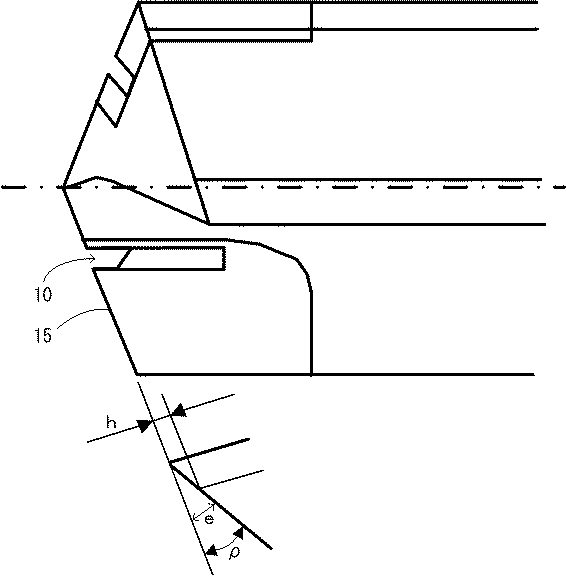
また、このチップ100の切れ刃部15には、その一部を切り欠いてなる、ドリルの軸方向の切取り厚さhよりも深く、すくい面11方向に長く伸びるクシ歯のようなスリット10が形成される。このようなスリット10を形成した場合、スリット箇所10におけるすくい面11と逃げ面12との交差稜線部(切れ刃)15は、チップの厚さ、すなわち、スリットの深さDの分だけ後退する。その切れ刃15の逃げ角ρ方向から見た後退量eが切取り厚さhよりも大きいと、そのスリット箇所10は切削に関与しないことから、切りくずが分断される。そして、これらのスリット10がチップ取付状態において回転軸に対して非対称になるように互いに半径方向にずらして配置され、それらの回転軌跡がそれぞれ異なるように構成されていることから、このスリット箇所10での削り残し部分は、半回転後にお互いの反対側にある切れ刃15によって1枚刃で切削される。つまり、これらのスリット部10を除く切れ刃15の1刃あたりの送り量は半回転当たりの送り量f/2となるのに対し、スリット部10の1刃あたりの送り量は一回転当たりの送り量fとなる。また、スリット部以外の切れ刃15における切取り厚さhに対し、スリット部10の切取り厚さはその2倍の2hとなる。
Further, the
このように本実施例に係るドリル200によれば切れ刃15にスリット10が形成されていることから切りくずの分断がおこり、この切りくずの分断により切削に伴い発生する切りくずが細かくなるので、穴あけ深さが増しても切りくずが滑らかに流出されて、切りくずが穴内面に当たって流出が妨げられることもなく、切りくずの厚さが増加したり、形状が変化したりすることがない。そのため、軸方向の切込み深さや回転当たりの送り量等を増大しても切りくず詰まりを起こすことがないので加工精度の良い加工穴を得ることができ、加工能率の向上を図ることができる。また、この細分化された切りくずは撓みやすくなるので、切りくずによる引っかき傷やむしれ跡が残りにくく、穴内面の粗さやうねり等の仕上げ面の品位に優れる。そして、穴が深くなっても、切りくず詰まりを起こすことも穴内面に拘束されることもないため、切削抵抗やトルクが増大、変動することがない。よって、穴出口側に発生するバリの抑制を図ることができるとともに、切れ刃の磨耗や欠損、ドリルの折損等を防止することができ、工具寿命に優れる。また、被削材への切りくずの残留を防止することができることから、穴あけ加工後にエアー等で洗浄して切りくずを除去する作業を省略または短縮することができるので作業効率が向上する。
As described above, according to the
このスリット10の数は、特に限定されるものではなく、求められる切りくずの幅によって複数のスリット10が適宜設けられる。
例えば、切れ刃部15に1つのスリット10が形成されたチップを2つ装着した2枚刃ドリル200を用いて穴あけを行うと、2枚の切れ刃15,15の各々のスリット箇所10,10において切りくずが縦に2分割されることとなるが(図6(a)参照)、2つのスリットが形成されたチップを装着した場合には切りくずが3分割されることになるため、2分割の場合よりも幅の狭い切りくずを得ることができる。つまり、スリット数を増加することにより切りくずの微細化を図ることが可能となる。
The number of
For example, when drilling is performed using a two-
また、スリット幅Wは、スリット部以外の切れ刃15およびスリット部10の切れ刃がなるべく均等に配分されるような範囲内において、求められる切りくずの幅によって適宜設計される。
この場合において、スリット数を増加することによる切りくずの微細化の点を考慮すると、スリット幅Wは小さくすることが好ましい。チップ幅Wが一定のときは、スリットの幅Wが狭ければ狭いほどスリット数を増加することができるからである。
The slit width W is appropriately designed according to the required chip width within a range in which the cutting edges 15 other than the slit portion and the cutting edges of the
In this case, it is preferable to reduce the slit width W in consideration of chip miniaturization by increasing the number of slits. This is because when the chip width W is constant, the narrower the slit width W, the larger the number of slits.
例えば、チップ幅Aを5mm、スリットの間隔Iを1.0mmとした場合、スリット幅Wが1.0mmのときは、2枚のチップ100,100の夫々の切れ刃15,15に1つずつしかスリットを構成することができず、得られる切りくずは4つに分割されたものとなる(図6(c)参照)。これに対し、スリット幅Wが0.3mmのときは、一方のチップ100の切れ刃15には1つのスリット10、もう一方のチップ100の切れ刃15には2つスリット10,10を構成することができるので、得られる切りくずは5分割されたものとなる(図6(b)参照)。よって、スリット幅Wを1.0mmとするより0.3mmに設定した方が切りくずが微細化されるので、切りくず処理性が向上するといえる。
For example, when the chip width A is 5 mm and the slit interval I is 1.0 mm, and the slit width W is 1.0 mm, one for each of the cutting edges 15 and 15 of the two
このように切りくずの微細化を目的としてドリル全体として設けられるスリット10の数を可能な限り多く設定する場合においては、一対のチップ取付座20,20に接合される2つのチップ100,100のうち、一方のチップ100の切れ刃15に形成されたスリット10と、このスリット箇所10の削り残し部分を半回転後に切削するこのチップ100と反対側に配置された、他方のチップ100の切れ刃15に形成されたスリット10との間隔Iを一定としたときの、スリットの幅Wと切りくずの幅の最大値Bとの関係式は、下記の式により表すことができる。
実際には、ドリルの先端角の角度αによって発生する切りくずの幅は異なるので、最大切りくず幅Cは、理論的には下記の式によって求められることになる(図6(d)参照)。
すなわち、先端角αが140°の2枚刃ドリル200に接合された、チップ幅Aが5mmの各チップ100,100の切れ刃15,15に、チップ取付状態において互いの反対側に配置されるスリット10とスリット10の間隔Iが1.0mmとなるようにスリットが構成されている場合において、スリット幅Wを1.0mmとしたときは、切りくずの幅の最大値Bは3.0mmとなり、θが20°となることから、最大切りくず幅Cは3.19mmとなる。これに対し、同条件の下、スリット幅Wを0.3mmとしたときは、最大切りくず幅Cは2.45mmとなる。したがって、スリット幅Wを1.0mmとするより0.3mmとする方が、得られる切りくずの幅Cが狭くなり、切りくず処理性が向上するといえる。
That is, the cutting edges 15 and 15 of the
このようなドリルが好適に用いられる代表的な例としては、自動車のオートマティックトランスミッション部品であるコントロールバルブボディのスプール穴やエンジンなどの製造工程における穴あけ加工等が挙げられる。このコントロールバルブボディには油圧回路を構成する作動油の流路溝があり、その幅が約3mm程度と狭いことから、それよりも幅の狭い切りくずが求められている。そこで、上記条件の下、スリット幅Wを0.3mmに設計すれば、最大切りくず幅Cが2.45mmと小さくなることから、油圧回路への切りくず残存の恐れがなく、切りくず処理性が向上すると考える。これに対し、スリット幅Wを1.0mmとしたときには、最大切りくず幅Cは3.19mmとなり、切りくず詰まりを起こす恐れがあるので好ましくない。 Typical examples of such drills that can be suitably used include a spool hole of a control valve body, which is an automatic transmission part of an automobile, and a drilling process in a manufacturing process of an engine or the like. The control valve body has a hydraulic oil flow path groove that constitutes a hydraulic circuit, and its width is as narrow as about 3 mm. Therefore, a chip having a narrower width is required. Therefore, if the slit width W is designed to be 0.3 mm under the above conditions, the maximum chip width C will be as small as 2.45 mm. Will improve. On the other hand, when the slit width W is 1.0 mm, the maximum chip width C is 3.19 mm, which may cause chip clogging.
以上より、特に、工具径が8mm以上18mm以下である小径のドリルに接合されるような小いさなチップである場合には、このスリットの幅Wの下限は0.2mmが好ましく、上限は0.8mmが好ましい。スリットの幅Wが0.8mmより大きいと、チップの幅Aが小さい場合にはスリット数を増やすことができず、スリット数の増加によって切りくずの微細化を図る場合に問題が生じるからである。また、このスリットの幅Wが0.2mmより小さいと却って切りくずの分断による効果を十分に得られない可能性があるからである。
この点、本実施例に係るドリル200においては、チップ取付座20に接合する前のチップ100の切れ刃部15に、あらかじめワイヤカット、レーザー加工、電子ビーム加工等の放電加工によりスリット10を形成することになるので、このようなスリット幅Wが0.2mm以上0.8mm以下の狭いスリットであっても、容易に能率よく加工形成することができる。
From the above, in particular, in the case of a small tip to be joined to a small diameter drill having a tool diameter of 8 mm or more and 18 mm or less, the lower limit of the width W of this slit is preferably 0.2 mm, and the upper limit is 0. .8 mm is preferred. This is because if the slit width W is larger than 0.8 mm, the number of slits cannot be increased when the chip width A is small, and a problem arises when the chip is miniaturized by increasing the number of slits. . Further, if the width W of the slit is smaller than 0.2 mm, there is a possibility that the effect due to the cutting of the chips cannot be obtained sufficiently.
In this respect, in the
また、スリットの長さLは、スリット箇所10を境にチップ100が折れない程度であれば、特に限定されないが、再研磨を想定した長さの範囲内において適宜設計される。
このように切りくず分断のためのスリット10が、所定の長さLで切れ刃15からすくい面11に沿って伸びるように構成されることから、ドリル200の切れ刃15を再研磨した場合に、スリット10を再成形しなくても新品時と同様の性能を得ることができる。つまり、切れ刃15を再研磨する度にスリット10を再加工する必要がないため、研磨の前後においてスリット10の位置、形状等がずれることがなく、再研磨前と同様の加工穴の表面粗さ、真円度等を得ることができる。よって、再研磨毎にニックを加工する必要がある、図7に示されるような、切りくず分断のためのニック30が切れ刃から逃げ面32に沿って設けられている従来のニック付ドリル300に比べ、作業効率に優れる。
Further, the length L of the slit is not particularly limited as long as the
Since the
なお、本実施例として、主として深穴加工に用いられるストレート溝21を有するドリル200を例に挙げて説明したが、これに限定されるものではなく、ツイストドリル、ガンドリル、ガンリーマ、コアドリル等多種の穴あけ工具に適用することができる。
In the present embodiment, the
また、ドリル200に取り付けられるチップの切れ刃部15には、耐チッピング性の向上を図る観点から刃先強化処理として、すくい面視した幅が切取り厚さhよりも大きくなるようなホーニングを施してもよい(図4(b)参照)。
In addition, the
10 スリット
11 すくい面
12 逃げ面
15 切れ刃(切れ刃部)
20 チップ取付座
100 チップ
200 ドリル
A チップ幅
D スリットの深さ(チップの厚さ)
L スリットの長さ
W スリット幅
10 slit 11
20
L Slit length W Slit width
Claims (3)
この穴あけ工具に取り付ける前におけるチップの切れ刃部の一部を、ワイヤカット、レーザー加工、電子ビーム加工等の放電加工により、前記切れ刃部から前記すくい面方向に向かって切り欠いて、前記チップの厚さ方向に貫通しつつ前記すくい面方向に伸びるスリットを形成する工程を備える
ことを特徴とする穴あけ工具に取り付けられるチップの製造方法。 It has a substantially flat plate shape, a rake face provided on the upper surface, a flank face provided on a side surface intersecting with the rake face, and a cutting edge part provided on an intersecting ridge line portion between the rake face and the flank face. The cutting edge portion is formed from an ultra-high pressure sintered body such as a diamond sintered body, a cubic boron nitride sintered body, and the like, and a manufacturing method of a chip attached to a drilling tool,
A part of the cutting edge part of the chip before being attached to the drilling tool is cut out from the cutting edge part toward the rake face direction by electric discharge machining such as wire cutting, laser machining, electron beam machining, etc. A method of manufacturing a tip attached to a drilling tool, comprising the step of forming a slit extending in the rake face direction while penetrating in the thickness direction of the drilling tool.
前記チップ取付座に前記穴あけ工具に取り付けられるチップを接合する工程と、
この接合された穴あけ工具に取り付けられるチップの前記切れ刃部を研磨して切れ刃を形成する工程を備える
ことを特徴とする穴あけ工具の製造方法。 A tip attached to a drilling tool manufactured by the manufacturing method of a tip attached to a drilling tool according to claim 1 is placed on a tip mounting seat formed at a tip of a drilling tool body, and the slit is a tip of the tool. A step of extending from the side toward the rear end side;
Joining the chip attached to the drilling tool to the chip mounting seat;
The manufacturing method of the drilling tool characterized by including the process of grind | polishing the said cutting blade part of the chip | tip attached to this joined drilling tool, and forming a cutting blade.
ことを特徴とする穴あけ工具。 A drilling tool manufactured by the method for manufacturing a drilling tool according to claim 2.
Priority Applications (1)
| Application Number | Priority Date | Filing Date | Title |
|---|---|---|---|
| JP2006245579A JP2008062369A (en) | 2006-09-11 | 2006-09-11 | Method of producing tip to be mounted on boring tool, method of producing boring tool, and boring tool |
Applications Claiming Priority (1)
| Application Number | Priority Date | Filing Date | Title |
|---|---|---|---|
| JP2006245579A JP2008062369A (en) | 2006-09-11 | 2006-09-11 | Method of producing tip to be mounted on boring tool, method of producing boring tool, and boring tool |
Publications (1)
| Publication Number | Publication Date |
|---|---|
| JP2008062369A true JP2008062369A (en) | 2008-03-21 |
Family
ID=39285504
Family Applications (1)
| Application Number | Title | Priority Date | Filing Date |
|---|---|---|---|
| JP2006245579A Pending JP2008062369A (en) | 2006-09-11 | 2006-09-11 | Method of producing tip to be mounted on boring tool, method of producing boring tool, and boring tool |
Country Status (1)
| Country | Link |
|---|---|
| JP (1) | JP2008062369A (en) |
Cited By (6)
| Publication number | Priority date | Publication date | Assignee | Title |
|---|---|---|---|---|
| JP2012040661A (en) * | 2010-08-20 | 2012-03-01 | Toshiba Mach Co Ltd | Core drill for machining cast hole |
| JP2013508168A (en) * | 2009-10-23 | 2013-03-07 | ケンナメタル インコーポレイテッド | 3D surface forming of rotary cutting tool blades by laser |
| US20160175944A1 (en) * | 2014-12-19 | 2016-06-23 | Metal Industries Research & Development Centre | Cutting tool with asymmetric structures on cutting teeth |
| JP2018516178A (en) * | 2015-04-20 | 2018-06-21 | ワルター マシーネンバオ ゲーエムベーハー | Method and apparatus for machining a tool by removing material |
| US10105769B2 (en) | 2014-04-17 | 2018-10-23 | Kennametal Inc. | Machining tool and method for manufacturing a machining tool |
| US10369636B2 (en) | 2014-04-17 | 2019-08-06 | Kennametal Inc. | Machining tool and method for manufacturing a machining tool |
Citations (7)
| Publication number | Priority date | Publication date | Assignee | Title |
|---|---|---|---|---|
| JPS5775714A (en) * | 1980-10-30 | 1982-05-12 | Toshiaki Hosoi | Drill |
| JPS5880114U (en) * | 1981-11-26 | 1983-05-31 | 三菱マテリアル株式会社 | double-blade drilling tool |
| JPS60117014U (en) * | 1984-01-18 | 1985-08-07 | 三菱重工業株式会社 | Tool head for deep hole machining |
| JPH01166015U (en) * | 1988-05-11 | 1989-11-21 | ||
| JPH0290005U (en) * | 1988-07-22 | 1990-07-17 | ||
| JPH06339801A (en) * | 1993-05-31 | 1994-12-13 | G N Tool Kk | Cutting tool |
| JPH10109210A (en) * | 1996-09-30 | 1998-04-28 | Ngk Spark Plug Co Ltd | Throw away tip for spade drill |
-
2006
- 2006-09-11 JP JP2006245579A patent/JP2008062369A/en active Pending
Patent Citations (7)
| Publication number | Priority date | Publication date | Assignee | Title |
|---|---|---|---|---|
| JPS5775714A (en) * | 1980-10-30 | 1982-05-12 | Toshiaki Hosoi | Drill |
| JPS5880114U (en) * | 1981-11-26 | 1983-05-31 | 三菱マテリアル株式会社 | double-blade drilling tool |
| JPS60117014U (en) * | 1984-01-18 | 1985-08-07 | 三菱重工業株式会社 | Tool head for deep hole machining |
| JPH01166015U (en) * | 1988-05-11 | 1989-11-21 | ||
| JPH0290005U (en) * | 1988-07-22 | 1990-07-17 | ||
| JPH06339801A (en) * | 1993-05-31 | 1994-12-13 | G N Tool Kk | Cutting tool |
| JPH10109210A (en) * | 1996-09-30 | 1998-04-28 | Ngk Spark Plug Co Ltd | Throw away tip for spade drill |
Cited By (9)
| Publication number | Priority date | Publication date | Assignee | Title |
|---|---|---|---|---|
| JP2013508168A (en) * | 2009-10-23 | 2013-03-07 | ケンナメタル インコーポレイテッド | 3D surface forming of rotary cutting tool blades by laser |
| US9463531B2 (en) | 2009-10-23 | 2016-10-11 | Kennametal Inc. | Three-dimensional surface shaping of rotary cutting tool edges with lasers |
| JP2012040661A (en) * | 2010-08-20 | 2012-03-01 | Toshiba Mach Co Ltd | Core drill for machining cast hole |
| US10105769B2 (en) | 2014-04-17 | 2018-10-23 | Kennametal Inc. | Machining tool and method for manufacturing a machining tool |
| US10369636B2 (en) | 2014-04-17 | 2019-08-06 | Kennametal Inc. | Machining tool and method for manufacturing a machining tool |
| US10646936B2 (en) | 2014-04-17 | 2020-05-12 | Kennametal Inc. | Machining tool and method for manufacturing a machining tool |
| US20160175944A1 (en) * | 2014-12-19 | 2016-06-23 | Metal Industries Research & Development Centre | Cutting tool with asymmetric structures on cutting teeth |
| JP2018516178A (en) * | 2015-04-20 | 2018-06-21 | ワルター マシーネンバオ ゲーエムベーハー | Method and apparatus for machining a tool by removing material |
| US10401827B2 (en) | 2015-04-20 | 2019-09-03 | Walter Maschinenbau Gmbh | Method and device for machining a tool by removing material |
Similar Documents
| Publication | Publication Date | Title |
|---|---|---|
| US6290438B1 (en) | Reaming tool and process for its production | |
| JP4919182B2 (en) | Drilling tool | |
| EP2012958B2 (en) | Face milling cutter | |
| EP1322441B1 (en) | Cutting tool and method and apparatus for making the same | |
| JP2008264979A (en) | Rotary cutting tool for drilling | |
| WO2018123133A1 (en) | Cutting tool and method for manufacturing same | |
| JP2008062369A (en) | Method of producing tip to be mounted on boring tool, method of producing boring tool, and boring tool | |
| JP2005111651A (en) | Tip, milling cutter, and machining method using the same | |
| EP1559493A2 (en) | Ballnose end mill | |
| JP4798669B2 (en) | Reamer | |
| JP2010094766A (en) | Boring tool | |
| JP4816723B2 (en) | insert | |
| JP2010179450A (en) | Boring tool | |
| JP2010046733A (en) | Thread milling cutter | |
| WO2021066046A1 (en) | Rotary cutting tool | |
| JP5953173B2 (en) | Cutting tools | |
| JP4608062B2 (en) | Burnishing drill | |
| JP6086180B1 (en) | Replaceable blade cutting tool and insert | |
| KR102470286B1 (en) | Mirror finishing method and mirror finishing tool | |
| JP2007313590A (en) | Thread cutting tip, and its manufacturing method | |
| JP2013013962A (en) | Cbn end mill | |
| JPH0760547A (en) | Thread cutting tool and manufacture thereof | |
| JP2006088242A (en) | Drilling tool | |
| JP4781224B2 (en) | Reamer | |
| JP4623674B2 (en) | Rotary cutting tool |
Legal Events
| Date | Code | Title | Description |
|---|---|---|---|
| A621 | Written request for application examination |
Effective date: 20090727 Free format text: JAPANESE INTERMEDIATE CODE: A621 |
|
| A131 | Notification of reasons for refusal |
Free format text: JAPANESE INTERMEDIATE CODE: A131 Effective date: 20111227 |
|
| A977 | Report on retrieval |
Effective date: 20111227 Free format text: JAPANESE INTERMEDIATE CODE: A971007 |
|
| A521 | Written amendment |
Effective date: 20120217 Free format text: JAPANESE INTERMEDIATE CODE: A523 |
|
| A02 | Decision of refusal |
Free format text: JAPANESE INTERMEDIATE CODE: A02 Effective date: 20120313 |