JP2008049563A - Image processor, image recorder and recording data forming method - Google Patents
Image processor, image recorder and recording data forming method Download PDFInfo
- Publication number
- JP2008049563A JP2008049563A JP2006227179A JP2006227179A JP2008049563A JP 2008049563 A JP2008049563 A JP 2008049563A JP 2006227179 A JP2006227179 A JP 2006227179A JP 2006227179 A JP2006227179 A JP 2006227179A JP 2008049563 A JP2008049563 A JP 2008049563A
- Authority
- JP
- Japan
- Prior art keywords
- recording
- dot
- recording data
- data
- dots
- Prior art date
- Legal status (The legal status is an assumption and is not a legal conclusion. Google has not performed a legal analysis and makes no representation as to the accuracy of the status listed.)
- Pending
Links
Images


Classifications
-
- G—PHYSICS
- G06—COMPUTING; CALCULATING OR COUNTING
- G06K—GRAPHICAL DATA READING; PRESENTATION OF DATA; RECORD CARRIERS; HANDLING RECORD CARRIERS
- G06K15/00—Arrangements for producing a permanent visual presentation of the output data, e.g. computer output printers
- G06K15/02—Arrangements for producing a permanent visual presentation of the output data, e.g. computer output printers using printers
-
- B—PERFORMING OPERATIONS; TRANSPORTING
- B41—PRINTING; LINING MACHINES; TYPEWRITERS; STAMPS
- B41J—TYPEWRITERS; SELECTIVE PRINTING MECHANISMS, i.e. MECHANISMS PRINTING OTHERWISE THAN FROM A FORME; CORRECTION OF TYPOGRAPHICAL ERRORS
- B41J2/00—Typewriters or selective printing mechanisms characterised by the printing or marking process for which they are designed
- B41J2/005—Typewriters or selective printing mechanisms characterised by the printing or marking process for which they are designed characterised by bringing liquid or particles selectively into contact with a printing material
- B41J2/01—Ink jet
- B41J2/21—Ink jet for multi-colour printing
- B41J2/2121—Ink jet for multi-colour printing characterised by dot size, e.g. combinations of printed dots of different diameter
- B41J2/2128—Ink jet for multi-colour printing characterised by dot size, e.g. combinations of printed dots of different diameter by means of energy modulation
-
- B—PERFORMING OPERATIONS; TRANSPORTING
- B41—PRINTING; LINING MACHINES; TYPEWRITERS; STAMPS
- B41J—TYPEWRITERS; SELECTIVE PRINTING MECHANISMS, i.e. MECHANISMS PRINTING OTHERWISE THAN FROM A FORME; CORRECTION OF TYPOGRAPHICAL ERRORS
- B41J29/00—Details of, or accessories for, typewriters or selective printing mechanisms not otherwise provided for
- B41J29/38—Drives, motors, controls or automatic cut-off devices for the entire printing mechanism
-
- G—PHYSICS
- G06—COMPUTING; CALCULATING OR COUNTING
- G06K—GRAPHICAL DATA READING; PRESENTATION OF DATA; RECORD CARRIERS; HANDLING RECORD CARRIERS
- G06K15/00—Arrangements for producing a permanent visual presentation of the output data, e.g. computer output printers
- G06K15/02—Arrangements for producing a permanent visual presentation of the output data, e.g. computer output printers using printers
- G06K15/18—Conditioning data for presenting it to the physical printing elements
- G06K15/1801—Input data handling means
- G06K15/181—Receiving print data characterized by its formatting, e.g. particular page description languages
- G06K15/1814—Receiving print data characterized by its formatting, e.g. particular page description languages including print-ready data, i.e. data already matched to the printing process
-
- H—ELECTRICITY
- H04—ELECTRIC COMMUNICATION TECHNIQUE
- H04N—PICTORIAL COMMUNICATION, e.g. TELEVISION
- H04N1/00—Scanning, transmission or reproduction of documents or the like, e.g. facsimile transmission; Details thereof
- H04N1/40—Picture signal circuits
- H04N1/405—Halftoning, i.e. converting the picture signal of a continuous-tone original into a corresponding signal showing only two levels
- H04N1/4055—Halftoning, i.e. converting the picture signal of a continuous-tone original into a corresponding signal showing only two levels producing a clustered dots or a size modulated halftone pattern
- H04N1/4057—Halftoning, i.e. converting the picture signal of a continuous-tone original into a corresponding signal showing only two levels producing a clustered dots or a size modulated halftone pattern the pattern being a mixture of differently sized sub-patterns, e.g. spots having only a few different diameters
-
- H—ELECTRICITY
- H04—ELECTRIC COMMUNICATION TECHNIQUE
- H04N—PICTORIAL COMMUNICATION, e.g. TELEVISION
- H04N1/00—Scanning, transmission or reproduction of documents or the like, e.g. facsimile transmission; Details thereof
- H04N1/41—Bandwidth or redundancy reduction
- H04N1/4105—Bandwidth or redundancy reduction for halftone screened pictures
Landscapes
- Engineering & Computer Science (AREA)
- General Engineering & Computer Science (AREA)
- Physics & Mathematics (AREA)
- General Physics & Mathematics (AREA)
- Theoretical Computer Science (AREA)
- Multimedia (AREA)
- Signal Processing (AREA)
- Computational Linguistics (AREA)
- Ink Jet (AREA)
- Particle Formation And Scattering Control In Inkjet Printers (AREA)
- Accessory Devices And Overall Control Thereof (AREA)
- Record Information Processing For Printing (AREA)
Abstract
Description
本発明は、画像処理装置、画像記録装置および記録データ生成方法に関し、詳しくは、大きさの異なるドットを形成して記録を行う記録装置で使用される記録データの生成に関するものである。 The present invention relates to an image processing apparatus, an image recording apparatus, and a recording data generation method. More specifically, the present invention relates to generation of recording data used in a recording apparatus that performs recording by forming dots having different sizes.
記録装置は、プリンタ、複写機、ファクシミリ等で記録を行う装置あるいはコンピュータやワードプロセッサ等を含む複合電子機器やワークステーション等の出力機器として用いられている。これらの記録装置は、画像情報(文字情報等すべての出力情報を含む)に基づいて用紙やプラスチック薄板等の記録媒体に画像等を記録するように構成されている。 The recording apparatus is used as an apparatus for recording with a printer, a copying machine, a facsimile, or the like, or an output apparatus such as a composite electronic apparatus including a computer or a word processor or a workstation. These recording apparatuses are configured to record an image or the like on a recording medium such as paper or a plastic thin plate based on image information (including all output information such as character information).
これらの記録装置の中でも、インクジェット方式の装置は、記録ヘッドから記録媒体にインクを吐出して記録を行うものである。この方式の記録装置は高精細化が容易で高速性、静粛性に優れ、また、安価に製造できるという、種々の利点を有している。インクジェット記録装置では、インク吐出口および液路を複数配列した吐出口列をインク色毎に備えた記録ヘッドが用いられる。そして、吐出口の数を多数配列した記録ヘッドを用いることにより、記録のスループットを向上させている。 Among these recording apparatuses, an inkjet apparatus performs recording by ejecting ink from a recording head onto a recording medium. This type of recording apparatus has various advantages that it is easy to achieve high definition, is excellent in high speed and quietness, and can be manufactured at low cost. In an ink jet recording apparatus, a recording head having an ink discharge port and a discharge port array in which a plurality of liquid paths are arranged for each ink color is used. The recording throughput is improved by using a recording head in which a large number of ejection openings are arranged.
近年では、カラー記録の需要も高まり、銀塩写真に匹敵する高画質の記録を行うことができるカラーインクジェットプリンタも数多く提供されている。 In recent years, the demand for color recording has increased, and many color ink jet printers that can perform high-quality recording comparable to silver salt photography have been provided.
このような高画質記録が可能なインクジェット記録装置における一構成として、一つの色に対し複数の大きさのドットを形成して記録を行うものが知られている(特許文献1)。この構成によれば、画像のハイライト部では相対的に小さいドットを優先的に使用することによって粒状感を低減し、グレー(ダーク)部分では相対的に大きい記録ドットを優先的に使用することにより少ないドットで濃度を向上させることができる。 As one configuration in an ink jet recording apparatus capable of such high image quality recording, one that performs recording by forming dots of a plurality of sizes for one color is known (Patent Document 1). According to this configuration, graininess is reduced by preferentially using relatively small dots in the highlight portion of the image, and relatively large recording dots are preferentially used in the gray (dark) portion. The density can be improved with fewer dots.
さらに、特許文献2では、こうした複数の大きさのドットの記録データ生成について大きさの異なるドットごとに独立した量子化を行い、これにより、記録品位などに対するドット配置設計の自由度を向上させる提案をしている。
Further,
しかしながら、特許文献2に記載のように大きさの異なるドットごとに独立に記録データ生成を行う構成では、記録に用いるドットの大きさの種類に応じて生成されあるいは処理されるデータの量が多くなる。特許文献2に記載の例では、シアン(C)、マゼンタ(M)、イエロー(Y)の各色について大、小の2種類の大きさのドットを用いるが、この場合、量子化によって生成する各色の大、小ドットの記録データは、それぞれ4ビットのデータとして生成される。このように、1つの色でドットの大きさの種類が1つ増すごとに4ビット分データ量が増すことになる。そして、このデータ量が多い場合次のような不都合を生じることがある。
However, in the configuration in which print data generation is performed independently for each dot having a different size as described in
例えば、ホスト装置からプリンタに記録データを転送する際に、転送するデータ量が増すことによってプリンタ側の記録速度に転送が間に合わない事態が生じることがある。このように、記録装置の記録速度に対し記録データ転送が間に合わない場合は、記録装置は記録データの受信待ちとなり、記録途中で記録データ待ちが発生するたびに不規則に記録を停止する必要が生じる。その結果、スループットの低下や記録品位の低下を招くことになる。 For example, when recording data is transferred from the host device to the printer, there may be a situation where the transfer is not in time for the recording speed on the printer side due to an increase in the amount of data to be transferred. As described above, when the recording data cannot be transferred in time for the recording speed of the recording apparatus, the recording apparatus waits for reception of the recording data, and it is necessary to stop recording irregularly every time recording data wait occurs during recording. Arise. As a result, throughput and recording quality are reduced.
また、ホスト装置で記録データを生成する場合に限らず、記録装置内で記録データを生成する構成にあっても、処理するデータ量が多くなることは好ましくない場合がある。例えば、メモリの容量を記録に用いるドットの大きさの数に応じて大きくする必要があり、その結果、記録装置におけるメモリの使用が制限されるなどの弊害をもたらす。 Further, not only when the recording data is generated in the host device, but also in the configuration in which the recording data is generated in the recording device, it may not be preferable to increase the amount of data to be processed. For example, it is necessary to increase the memory capacity in accordance with the number of dots used for recording, and as a result, the use of the memory in the recording apparatus is restricted.
本発明は上記問題点を解消するためになされたものであり、その目的は、大きさが異なるドットごとに生成される記録データのデータ量を少なくすることが可能な画像処理装置および記録データ生成方法を提供することである。 The present invention has been made to solve the above problems, and an object of the present invention is to provide an image processing apparatus and print data generation capable of reducing the amount of print data generated for each dot having a different size. Is to provide a method.
そのために本発明の画像処理装置は、第1ドットを記録するための第1の記録データと、前記第1ドットと同色で前記第1ドットよりも小さい第2ドットを記録するための第2の記録データを生成するための生成手段を有し、前記第2の記録データの1画素あたりのビット数は、前記第1の記録データの1画素あたりのビット数よりも小さいことを特徴とする。 For this purpose, the image processing apparatus of the present invention includes a first recording data for recording the first dot and a second dot for recording a second dot having the same color as the first dot and smaller than the first dot. And generating means for generating recording data, wherein the number of bits per pixel of the second recording data is smaller than the number of bits per pixel of the first recording data.
他の形態の画像処理装置は、第1ドットを記録するための第1の記録データと、前記第1ドットと同系色で前記第1ドットよりも濃度の低い第2ドットを記録するための第2の記録データを生成するための生成手段を有し、前記第2の記録データの1画素あたりのビット数は、前記第1の記録データの1画素あたりのビット数よりも小さいことを特徴とする。 In another form of the image processing apparatus, the first recording data for recording the first dot and the second dot for recording the second dot having the same color as the first dot and lower in density than the first dot. Generating means for generating the second recording data, wherein the number of bits per pixel of the second recording data is smaller than the number of bits per pixel of the first recording data. To do.
また、本発明の画像記録装置は、第1ドットと前記第1ドットと同色で前記第1ドットよりも小さい第2ドットを記録可能な画像記録装置であって、第1ドットを記録するための第1の記録データに基づいて前記第1ドットを記録し、前記第1ドットと同色で前記第1ドットよりも小さい第2ドットを記録するための第2の記録データに基づいて前記第2ドットを記録する手段を有し、前記第2の記録データの1画素あたりのビット数は、前記第1の記録データの1画素あたりのビット数よりも小さいことを特徴とする。 また、本発明の記録データ生成方法は、第1ドットを記録するための第1の記録データと、前記第1ドットと同色で前記第1ドットよりも小さい第2ドットを記録するための第2の記録データを生成するための生成工程を有し、前記第2の記録データの1画素あたりのビット数は、前記第1の記録データの1画素あたりのビット数よりも小さいことを特徴とする。 The image recording apparatus of the present invention is an image recording apparatus capable of recording a first dot and a second dot that is the same color as the first dot and is smaller than the first dot, for recording the first dot. The first dot is recorded based on the first recording data, and the second dot is recorded based on the second recording data for recording the second dot having the same color as the first dot and smaller than the first dot. The number of bits per pixel of the second recording data is smaller than the number of bits per pixel of the first recording data. The recording data generation method of the present invention includes a first recording data for recording the first dot and a second dot for recording a second dot having the same color as the first dot and smaller than the first dot. A generation step for generating the recording data of the second recording data, wherein the number of bits per pixel of the second recording data is smaller than the number of bits per pixel of the first recording data. .
以上の構成によれば、第1ドットの記録データのビット数よりも、第1のドットと同色で第1ドットより小さい第2ドット(あるいは第1ドットと同系色で第1ドットよりも濃度が低い第2ドット)の記録データのビット数を少なくする。これにより、生成される記録データの全体のデータ量を少なくすることができ、データ転送に要する時間を短くすることや、記録データを格納するためのメモリ領域を小さくすることが可能となる。 According to the above configuration, the second dot is the same color as the first dot and smaller than the first dot (or the same color as the first dot and has a density higher than that of the first dot than the number of bits of the recording data of the first dot. The number of bits of the recording data (low second dot) is reduced. As a result, the total amount of generated recording data can be reduced, the time required for data transfer can be shortened, and the memory area for storing recording data can be reduced.
以下、図面を参照して本発明の実施形態を詳細に説明する。
(実施形態1)
インクジェット記録装置の説明
図1は、本発明の一実施形態に係わるインクジェットプリンタを示す外観斜視図である。図1に示すように、記録装置としてのインクジェットプリンタ1は、インクジェット方式に従ってインクを吐出する記録ヘッド3を着脱自在に搭載したキャリッジ2を備える。キャリッジ2は、伝達機構4を介して伝えられるキャリッジモータM1の駆動力をよって、矢印A方向に往復移動することができる。この移動によって、記録ヘッド3は記録紙などの記録媒体P上を走査することができる。そして、この走査の間に記録ヘッド3から記録媒体Pにインクを吐出することにより走査領域に対する記録を行う。この記録ヘッド3の走査領域に対応して、搬送される記録媒体を支持するプラテン(不図示)が設けられている。給紙機構5はこの走査領域に対して記録媒体を給紙する。また、記録媒体の搬送機構は、記録ヘッドの走査ごとに記録媒体を上記走査領域の幅に対応した距離だけ搬送する。このように記録ヘッドの走査と記録媒体の所定量の搬送を繰返すことにより、記録媒体全体に記録を行うことができる。
Hereinafter, embodiments of the present invention will be described in detail with reference to the drawings.
(Embodiment 1)
DESCRIPTION OF INKJET RECORDING DEVICE FIG. 1 is an external perspective view showing an ink jet printer according to an embodiment of the present invention. As shown in FIG. 1, an
キャリッジ2には、記録ヘッド3のほかこのヘッドに供給するインクを貯留したインクカートリッジ6が同様に着脱自在に装着される。本実施形態では、シアン(C)、マゼンタ(M)、イエロー(Y)、ブラック(K)のインクをそれぞれ収容した4つのインクカートリッジを搭載している。記録ヘッド3はキャリッジ2に装着される際、双方の接合面が適正に接触して所要の電気的接続を達成維持できるようになっている。記録ヘッド3は、図4等で後述する画像処理によって生成される記録データに応じてインクを吐出する。本実施形態の記録ヘッド3は、熱エネルギーを利用してインクを吐出する方式を採用し、熱エネルギーを発生するための吐出口ごとに電気熱変換体を備える。すなわち、熱エネルギーをインクに与えることによって生じる膜沸騰による気泡の成長、収縮によって生じる圧力変化を利用して、吐出口からインクを吐出するものである。
In addition to the
キャリッジ2は、キャリッジモータM1の駆動力を伝達する伝達機構4の駆動ベルト7の一部に連結されており、ガイドシャフト13に沿って矢印A方向に摺動自在に案内支持されている。これにより、キャリッジ2は、キャリッジモータM1の正転および逆転に応じてガイドシャフト13に沿って往復移動することができる。また、キャリッジ2の移動方向(矢印A方向)に沿ってキャリッジ2の位置を検出するためのスケール8が設けられている。本実施形態では、スケール8は透明なPETフィルムに必要なピッチで黒色のバーを印刷したものを用いており、その一方はシャーシ9に固着され、他方は板バネ(不図示)で支持されている。
The
記録媒体Pの搬送機構は次のとおりである。図1において、14は搬送モータM2によって駆動される搬送ローラ、15はバネ(不図示)により記録媒体Pを搬送ローラ14に対して押圧するピンチローラをそれぞれ示す。また、16はピンチローラ15を回転自在に支持するピンチローラホルダ、17は搬送ローラ14の一端に固着された搬送ローラギアを示す。そして、搬送ローラギア17に中間ギア(不図示)を介して伝達された搬送モータM2の回転により、搬送ローラ14が駆動される。また、20は画像が形成された記録媒体Pを記録装置外へ排出するための排出ローラを示し、搬送モータM2によって駆動される。記録媒体Pは排出ローラ20に対してバネ(不図示)の不勢力を有した拍車ローラ(不図示)によって押圧される。22は拍車ローラを回転自在に支持する拍車ホルダを示している。
The transport mechanism for the recording medium P is as follows. In FIG. 1,
インクジェット記録装置の制御構成
図2は、主に図1に示したプリンタの制御構成を示すブロック図である。
Control block diagram 2 of the ink jet recording apparatus is a block diagram showing mainly a control configuration of the printer shown in FIG.
図2において、210はプリンタで用いる記録データの供給源となるコンピュータを示し、データ供給源として、以下ではホスト装置と称される。ホスト装置210は、図4に示す画像処理を行って記録データを生成する。ホスト装置210はプリンタ1との間で、インターフェース(I/F)211を介し上記記録データの他、記録処理に関連したコマンド、ステータス信号等を送受信する。なお、ホスト装置は、画像読取り用のリーダやデジタルカメラなどとすることもできる。
In FIG. 2,
プリンタ1において、コントローラ200は、ホスト装置210から送られる記録データなどに基づいてプリンタ1における記録動作の制御を行う。具体的には、MPU201が、ROM202に格納されたプログラムに従ってデータ処理ないし各部の制御を実行する。記録データに基づくドットデータの生成は、図4などにて後述されるようにホスト装置210から送られる、量子化された記録データが示す階調値レベルに応じたインデックスパターンを用いて行う。そして、生成されたドットデータはRAM204に展開される。
In the
ROM202は上記プログラムの他、所要のテーブル、上記インデックスパターンデータなどの固定データを格納する。RAM204には、記録データの展開領域やプログラム実行のための作業用領域等が設けられる。特殊用途集積回路(ASIC)203は、MPU201の制御に従い、キャリッジモータM1の制御や搬送モータM2の制御、さらには記録ヘッド3の制御のための制御信号を生成する。システムバス205は、MPU201、ASIC203、RAM204を相互に接続してデータの授受を行うためのデータ経路である。また、A/D変換器206は、次に説明するセンサ群からのアナログ信号をA/D変換しその変換されたデジタル信号をMPU201に供給する。ASIC203は、記録ヘッド3による記録走査の際に、RAM204の記憶領域に直接アクセスし、そのドットデータに基づいて、記録ヘッドのドライバに対して電気熱変換体の駆動データを転送する。
The
スイッチ群220は、電源スイッチ221、プリント開始を指令するためのプリントスイッチ222、及び記録ヘッド3のインク吐出性能を良好な状態に維持するための処理(回復処理)の起動を指示するための回復スイッチ223などを有する。これらのスイッチを介して操作者による指令入力を受けることができる。センサ群230は、ホームポジションを検出するためのフォトカプラなどの位置センサ231、環境温度を検出するために記録装置の適宜の箇所に設けられた温度センサ232等を有する。これらのセンサによって装置状態を検出することができる。キャリッジモータドライバ240は、キャリッジ2を矢印A方向に往復走査させるためのキャリッジモータM1の駆動を行う。搬送モータドライバ242は、記録媒体Pを搬送するための搬送モータM2の駆動を行う。
The
記録ヘッド
図3は、本実施形態の記録ヘッド3の詳細を示す模式図である。図3において、301はシアンインク用の記録ヘッド、302はマゼンタインク用の記録ヘッド、303はイエローインク用の記録ヘッド、304はブラックインク用の記録ヘッドである。図に示すように、これらの記録ヘッドは、それぞれ吐出するインク滴の体積(量)が異なる吐出口(以下、ノズルとも言う)を備える。シアンヘッド301は、5pl(ピコリットル)のノズル(以下、“大ノズル”とも言う)のノズル列301a、2plのノズル(以下“中ノズル”とも言う)のノズル列301b、1plのノズル(以下“小ノズル”とも言う)のノズル列301cを備える。マゼンタヘッド302も、シアンと同様吐出されるインク滴の大きさが5pl、2pl、1plのノズル列を備える。イエローヘッド303およびブラックヘッド304は、それぞれ5plのノズル(大ノズル)と2plのノズル(中ノズル)のノズル列を備える。上記4色の記録ヘッドそれぞれのノズル列は、図3に示すように主走査(x)方向に並ぶ構成である。この記録ヘッド構成により、大、中、小の各ノズルから吐出されるインク滴によって形成されるドットはその大きさについて、それぞれ大ドット、中ドット、小ドットとなる。
Recording Head FIG. 3 is a schematic diagram showing details of the
記録データ生成処理
図4は、ホスト装置210において実行される記録データ生成を含む一連の画像処理の手順を示すフローチャートである。
Recording Data Generation Processing FIG. 4 is a flowchart showing a series of image processing procedures including recording data generation executed in the
図4において、最初にステップS401で、画像データ(R、G、B)(R:レッド、G:グリーン、B:ブルー)を入力する処理を行う。本実施形態では、この画像データは、1画素あたり、R、G、Bそれぞれが8ビットのデータで構成されている。次に、ステップS402で、画像データ(R、G、B)に対し色補正処理を行いそれぞれ8ビットの画像データ(R’、G’、B’)を得る。この色補正処理によって、上記入力した画像データの表示を行う機器が再現可能な色域から、本プリンタの再現可能な色域への変換を行う。本実施形態では、この色補正処理を、LUT(ルックアップテーブル)を用いて行う。図10(a)は、このLUТを模式的に示す図である。具体的には、LUTにおいて、入力する画像データ(R、G、B)によって定まる補間空間を構成する格子点データを用いて補間演算を行い、画像データ(R’、G’、B’)を求める。 In FIG. 4, first, in step S401, processing for inputting image data (R, G, B) (R: red, G: green, B: blue) is performed. In the present embodiment, this image data is composed of 8-bit data for each of R, G, and B per pixel. In step S402, color correction processing is performed on the image data (R, G, B) to obtain 8-bit image data (R ', G', B '). By this color correction processing, the color gamut reproducible by the device that displays the input image data is converted to the color gamut reproducible by the printer. In the present embodiment, this color correction processing is performed using an LUT (Look Up Table). FIG. 10A is a diagram schematically showing this LUТ. Specifically, in the LUT, an interpolation operation is performed using grid point data constituting an interpolation space determined by input image data (R, G, B), and the image data (R ′, G ′, B ′) is obtained. Ask.
次に、ステップS403で色変換処理を行う。この処理は、画像データ(R’、G’、B’)を本プリンタ用いるインク色の記録データに変換する。この色変換処理は、画像データ(R’、G’、B’)の画素単位で行われる。本実施形態では、この色変換処理によって、記録ヘッドにおける大、中、小のノズルそれぞれについて記録データを得る。このように形成されるドットの大きさが異なることに対応して、ドットの大きさごとに記録データを得るような色変換を行う。具体的には、それぞれの色について大、中、小ノズルに対応したデータの組を求める。ここで、シアンについて、図3に示す大、中、小ノズルに対応したデータをそれぞれC、MC、SCとし、マゼンタについても同様、大、中、小ノズルに対応したれデータをそれぞれM、MM、SMとする。また、イエローについては大、中ノズルに対応したデータをそれぞれY、MYとし、ブラックについては大、中ノズルに対応したデータをそれぞれK、MKとする。このとき、本変換処理は、画像データ(R’、G’、B’)が示す色を表現する記録データ(C、M、Y、K、MC、MM、MY、MK、SC、SK)の組を求める処理である。この色変換処理も色補正処理と同様、LUTを用いて行なわれる。 Next, color conversion processing is performed in step S403. In this process, the image data (R ′, G ′, B ′) is converted into ink color recording data used by the printer. This color conversion processing is performed in units of pixels of image data (R ′, G ′, B ′). In this embodiment, print data is obtained for each of the large, medium, and small nozzles in the print head by this color conversion process. In response to the difference in the size of the dots formed in this way, color conversion is performed so as to obtain print data for each dot size. Specifically, a data set corresponding to the large, medium, and small nozzles is obtained for each color. Here, for cyan, the data corresponding to the large, medium, and small nozzles shown in FIG. 3 are C, MC, and SC, respectively, and for magenta, the data corresponding to the large, medium, and small nozzles are respectively M, MM. , SM. For yellow, the data corresponding to the large and medium nozzles are Y and MY, respectively, and for black, the data corresponding to the large and medium nozzles are respectively K and MK. At this time, this conversion processing is performed on the recording data (C, M, Y, K, MC, MM, MY, MK, SC, SK) representing the color indicated by the image data (R ′, G ′, B ′). This is a process for obtaining a set. This color conversion process is also performed using an LUT, similar to the color correction process.
図10(b)は、色変換処理に用いるLUТを模式的に示す図である。また、図5は、図10(b)のLUTにおけるWhite−Cyanライン上の色を変換して得られる記録データ(C、M、Y、K、MC、MM、MY、MK、SC、SK)のうち、シアンの大、中、小ドットに対応するデータC、MC、SCの値を示す図である。ここで、縦軸の打ち込み量は、大ドットが2個を形成するときの打ち込み量を「255」としたときの大、中、小それぞれの打ち込み量を表している。この図5に示すようなLUTの内容は、画像データ(R’、G’、B’)が示す色の階調性などを考慮して統一的に定めたものである。従って、色変換によって大、中、小ドットに対応する記録データを個別に生成しそれらに基づいて以下に示すように独立して量子化を行っても、それによって得られるドットデータ基づいて記録される画像は、意図した階調性などの画像とすることができる。 FIG. 10B is a diagram schematically showing LUТ used for color conversion processing. FIG. 5 shows recording data (C, M, Y, K, MC, MM, MY, MK, SC, SK) obtained by converting the color on the White-Cyan line in the LUT of FIG. It is a figure which shows the value of the data C, MC, and SC corresponding to the large, medium, and small dots of cyan among them. Here, the driving amount on the vertical axis represents the large, medium, and small driving amounts when the driving amount when two large dots are formed is “255”. The contents of the LUT as shown in FIG. 5 are uniformly determined in consideration of the gradation of the color indicated by the image data (R ′, G ′, B ′). Therefore, even if recording data corresponding to large, medium, and small dots are individually generated by color conversion and independently quantized as shown below based on them, they are recorded based on the dot data obtained thereby. The image can be an image having an intended gradation.
次のステップS404では、上記色変換処理によって得られたC、M、Y、K、MC、MM、MY、MK、SC、SMの各8ビットの記録データに対して量子化処理を行う。なお、量子化処理とは、N(Nは3以上の整数)ビットの記録データをNよりも小さいM(Mは1以上の整数)ビットの記録データに変換する処理をいう。これにより、量子化された記録データCd、Md、Yd、Kd、MCd、MMd、MYd、MKd、SCd、SMdを得る。本発明の実施形態では、以下に説明するように、大、中、小ドットに対応したデータごとに量子化処理を異ならせることにより、量子化によって得られる記録データのビット数を異ならせる。本例では、特に、大ドット用記録データの1画素あたりのビット数を、中、小ドット用記録データの1画素あたりのビット数とは異ならせる。これにより、大ドット用記録データが示す階調数を中、小ドット用記録データが示す階調数とは異ならせる。 In the next step S404, quantization processing is performed on 8-bit recording data of C, M, Y, K, MC, MM, MY, MK, SC, and SM obtained by the color conversion processing. The quantization process refers to a process of converting N (N is an integer of 3 or more) bits of recording data into M (M is an integer of 1 or more) bits of recording data smaller than N. Thereby, quantized recording data Cd, Md, Yd, Kd, MCd, MMd, MYd, MKd, SCd, and SMd are obtained. In the embodiment of the present invention, as described below, the number of bits of recording data obtained by quantization is varied by varying the quantization process for each data corresponding to large, medium, and small dots. In this example, in particular, the number of bits per pixel of the large dot recording data is made different from the number of bits per pixel of the medium and small dot recording data. As a result, the number of gradations indicated by the large dot recording data is made different from the number of gradations indicated by the small dot recording data.
本実施形態の量子化処理では、大ドットに対応する記録データC、M、Y、Kは2ビットの記録データCd、Md、Yd、Kdに量子化される。また、中、小に対応する記録データMM、MY、MK、SC、SMは、それぞれ1ビットの記録データに量子化される。 In the quantization process according to the present embodiment, the recording data C, M, Y, and K corresponding to the large dot are quantized into 2-bit recording data Cd, Md, Yd, and Kd. The recording data MM, MY, MK, SC, and SM corresponding to medium and small are each quantized into 1-bit recording data.
なお、これらの量子化処理は、ディザ法や誤差拡散法など公知の手法を用いるが、本発明の実施形態では量子化される記録データのビット数に応じて上記量子化の手法が異なることはもちろんである。この場合、図5に示す内容のテーブルにおいて考慮されている階調性などが維持されるようにドットの大きさごとの量子化が行われる。具体的には、図5にて上述したように、本実施形態の色変換テーブルは、600dpi×600dpiのサイズの1画素に対して2個の大ドットを形成するときの打ち込み量が255である。従って、例えばこの打ち込み量によって実現される階調値(濃度値)を基準として、大、中、小ドットそれぞれについてその打ち込み量による階調値を実現するように、ディザ法や誤差拡散法における閾値を定める。 These quantization processes use a known method such as a dither method or an error diffusion method. However, in the embodiment of the present invention, the quantization method differs depending on the number of bits of recording data to be quantized. Of course. In this case, the quantization for each dot size is performed so that the gradation property considered in the table of contents shown in FIG. 5 is maintained. Specifically, as described above with reference to FIG. 5, the color conversion table of the present embodiment has a shot amount of 255 when two large dots are formed for one pixel having a size of 600 dpi × 600 dpi. . Therefore, for example, the threshold value in the dither method or error diffusion method is used so that the gradation value according to the amount of ink is realized for each of the large, medium, and small dots with reference to the gradation value (density value) realized by this amount of ink. Determine.
図6(a)は、記録ヘッドごとに本実施形態に係わる1画素(600dpi×600dpiのサイズ)当りの大、中、小ドットそれぞれの記録データのビット数などを示す図である。一方、図6(b)は、比較例に係る同様の図である。 FIG. 6A is a diagram showing the number of bits of print data for each of large, medium, and small dots per pixel (size of 600 dpi × 600 dpi) according to the present embodiment for each print head. On the other hand, FIG. 6B is a similar view according to the comparative example.
図6(b)に示す比較例に係る従来の量子化は、大きさの異なるドットについて量子化されたときのデータ量(ビット量)について特に考慮せず一律2ビットとしている。これに対し、本実施形態では、図6(a)に示すように、各記録ヘッドにおいて、記録するドットの大きさを相対的に大きいグループ(5pl)と相対的に小さいグループ(2pl、1pl)に分類する。そして、量子化では、ドットが相対的に大きいグループの1画素当りのビット数を2ビット、記録ドットが相対的に小さいグループの1画素当りのビット数を1ビットとする。 In the conventional quantization according to the comparative example shown in FIG. 6B, the data amount (bit amount) when the dots having different sizes are quantized is not specifically taken into consideration and is uniformly 2 bits. In contrast, in the present embodiment, as shown in FIG. 6A, in each recording head, the size of dots to be recorded is a relatively large group (5 pl) and a relatively small group (2 pl, 1 pl). Classify into: In the quantization, the number of bits per pixel in a group having a relatively large dot is 2 bits, and the number of bits per pixel in a group having a relatively small recording dot is 1 bit.
これにより、比較例では、1画素当り:2[ビット]×10[色/ドットサイズ]=20[ビット]であるのに対し、本実施形態では、1画素当り:2[ビット]×4[色]+1[ビット]×6[色/ドットサイズ]=14[ビット]となる。このように、本実施形態によれば、比較例に対し1画素当り6ビット分のデータ量削減が可能となる。 Thereby, in the comparative example, per pixel: 2 [bits] × 10 [color / dot size] = 20 [bits], but in this embodiment, per pixel: 2 [bits] × 4 [per pixel]. Color] +1 [bit] × 6 [color / dot size] = 14 [bit]. Thus, according to the present embodiment, the data amount can be reduced by 6 bits per pixel as compared with the comparative example.
図7(a)および(b)は、ビットデータとドット数との関係を示す図である。図7(a)は1ビットデータが入力されたときのドット数を、図7(b)は2ビットデータが入力されたドット数をそれぞれ示している。 FIGS. 7A and 7B are diagrams showing the relationship between bit data and the number of dots. FIG. 7A shows the number of dots when 1-bit data is input, and FIG. 7B shows the number of dots when 2-bit data is input.
図7(a)の1ビットデータの場合、出力階調は「0」か「1」の2通りである。本実施形態では入力データ「0」のときはドットを0ドット、入力データ「1」のときはドットを1ドット形成することを示している。すなわち、図6(a)に示すように、1ビットデータの場合、出力階調数を2としている。 In the case of 1-bit data in FIG. 7A, there are two output gradations, “0” or “1”. In the present embodiment, when the input data is “0”, 0 dots are formed, and when the input data is “1”, one dot is formed. That is, as shown in FIG. 6A, in the case of 1-bit data, the number of output gradations is 2.
同様に図7(b)の2ビットデータの場合、出力階調は「00」「01」「10」「11」の4通りがある。それぞれの入力データに対する記録ドット数は0ドット、1ドット、2ドット、3ドットとする。すなわち、図6(a)に示すように、2ビットデータの場合、出力階調数を4としている。なお、上述したように、最大打ち込み量「255」に対して大ドットが2ドット形成されることから、これが大ドットの最大ドット数となり、従って、本実施形態では、大ドットが3ドット形成されることはない。 Similarly, in the case of the 2-bit data in FIG. 7B, there are four output gradations of “00”, “01”, “10”, and “11”. The number of recording dots for each input data is 0 dot, 1 dot, 2 dots, and 3 dots. That is, as shown in FIG. 6A, in the case of 2-bit data, the number of output gradations is 4. As described above, since two large dots are formed for the maximum shot amount “255”, this is the maximum number of large dots. Therefore, in this embodiment, three large dots are formed. Never happen.
以上のように、本実施形態では、同色で相対的に大きなドット(大ドット)よりも、相対的に小さなドット(中ドット、小ドット)のデータ量(ビット量)を少なくする。これにより、相対的に大きなドット(大ドット)よりも、相対的に小さなドット(中ドット、小ドット)の方が、1画素あたりに記録する最大ドット数が少なくなるようにしている。 As described above, in this embodiment, the data amount (bit amount) of a relatively small dot (medium dot, small dot) is smaller than that of a relatively large dot (large dot) of the same color. Thereby, a relatively small dot (medium dot, small dot) is smaller in the maximum number of dots recorded per pixel than a relatively large dot (large dot).
これは、
・大ドットが多いほど同じドット数で最大の打ち込みインク量を多くすることができ、高い濃度を出すのに有利な構成である、
・小ドットを形成する場合ほどつまり吐出量が少なくなるほどインク吐出が外乱に弱くなり、特に短時間に多数のドットを形成しようとすると着弾が乱れやすい、
・吐出量の種類が増してきていることから、吐出量の異なるドット間でのつなぎによる弊害が認識しづらくなっている、
ことから、1plや2plによる小、中ドットの1画素当りの数(すなわちビット数)を削減することが効果的であるからである。
this is,
-The larger the number of large dots, the larger the maximum amount of ink that can be ejected with the same number of dots, which is advantageous for producing a high density.
-The smaller the dots are formed, that is, the smaller the ejection amount, the weaker the ink ejection, especially when trying to form a large number of dots in a short time, the landing is likely to be disturbed.
-Since the types of discharge amount are increasing, it is difficult to recognize the negative effects caused by the connection between dots with different discharge amounts.
This is because it is effective to reduce the number of small and medium dots per pixel (that is, the number of bits) by 1 pl or 2 pl.
以上のように本実施形態によれば、相対的に小さいドットのための記録データの1画素あたりのビット数を相対的に大きいドットのための記録データの1画素あたりのビット数よりも少なくする。これにより、必要以上に画像品位や記録速度を低下することなく、記録データの量を少なくすることができる。 なお、本実施形態では、記録ドットの大きさを相対的に大きいグループを5pl、相対的に小さいグループを2plと1plとしているが、特にこれに限られないことはもちろんである。例えば、ドットの大きさを相対的に大きいグループを5plと2pl、相対的に小さいグループと1plとしてもよい。いずれの区分けが望ましいかは記録装置に求められる記録速度などから随時決定することができる。また、図7に示した各ビットに対するドット数、すなわち階調数も特に上記例に限定されない。 As described above, according to the present embodiment, the number of bits per pixel of recording data for relatively small dots is made smaller than the number of bits per pixel of recording data for relatively large dots. . As a result, the amount of recorded data can be reduced without degrading image quality and recording speed more than necessary. In this embodiment, the recording dot size is 5 pl for a relatively large group and 2 pl and 1 pl for relatively small groups, but it is needless to say that the present invention is not limited to this. For example, a relatively large group may be 5 pl and 2 pl, and a relatively small group may be 1 pl. Which classification is desirable can be determined as needed from the recording speed required for the recording apparatus. Also, the number of dots, that is, the number of gradations for each bit shown in FIG. 7 is not particularly limited to the above example.
再び図4を参照すると、ステップS404の量子化処理を終了すると、ホスト装置は量子化された記録データをプリンタ1に転送して記録を行わせる。
Referring to FIG. 4 again, when the quantization process in step S404 is completed, the host device transfers the quantized recording data to the
これに対し、プリンタ1では、例えば特許文献2に記載されるようなドット配置を示すインデックスパターン(ドット配置パターン)を用いて、各記録ヘッドに供給するドット(2値)データを生成する。本実施形態では、600dpi×600dpiの解像度の量子化記録データに対して、1画素が1200dpi×1200dpiの解像度の、2画素×2画素のインデックスパターンを用いる。例えば、2ビットデータが示すドット数が2(出力階調値レベルが3)の場合、2画素×2画素のうち所定の2箇所にドットを配置したインデックスパターン(ドット配置パターン)を用いる。また、1ビットデータが示すドット数が1(出力階調値レベルが2)の場合、2画素×2画素のうち所定の1箇所にドットを配置したインデックスパターンを用いる。このインデックスパターンに対応して、本実施形態の各記録ヘッドは、図3に示したように、1200dpiの密度でノズルを配列したものである。また、これらの記録ヘッドの走査ではその走査方向において1200dpiの密度でドットを形成する周波数で記録ヘッドを駆動する。
On the other hand, the
(実施形態1の変形例)
実施形態1では、図3や図6にて示した通り、同色でサイズの異なる複数種類のドットとして、大ドット、中ドット、小ドットの3種類を用いる場合について説明した。しかし、本発明では上述の3種類に限定されるものではない。
例えば、同色でサイズの異なる複数種類のドットとして、大ドットと小ドットの2種類を用いる形態であってもよい。大ドットと小ドットの2種類を用いる形態の場合、小ドット用の記録データの1画素あたりのビット数を、大ドット用の記録データの1画素あたりのビット数よりも少なくする。
また、別の形態として、同色でサイズの異なる複数種類のドットとして、大ドット(5pl)、中ドット(3pl)、小ドット(1pl)、極小ドット(0.5pl)の4種類を用いる形態であってもよい。この4種類を用いる形態の場合、小ドット、極小ドット用の記録データの1画素あたりのビット数を、大ドット、中ドット用の記録データの1画素あたりのビット数よりも少なくする。
(Modification of Embodiment 1)
In the first embodiment, as shown in FIGS. 3 and 6, the case where three types of large dots, medium dots, and small dots are used as a plurality of types of dots having the same color and different sizes has been described. However, the present invention is not limited to the above three types.
For example, two or more types of large dots and small dots may be used as a plurality of types of dots having the same color and different sizes. In the case of using two types of large dots and small dots, the number of bits per pixel of the recording data for small dots is made smaller than the number of bits per pixel of the recording data for large dots.
Further, as another form, as a plurality of kinds of dots of the same color and different sizes, four kinds of large dots (5 pl), medium dots (3 pl), small dots (1 pl), and extremely small dots (0.5 pl) are used. There may be. In the case of using these four types, the number of bits per pixel of recording data for small dots and extremely small dots is made smaller than the number of bits per pixel of recording data for large dots and medium dots.
(実施形態2)
上述した実施形態1では、図7(a)に示したように1ビットデータの中ドットや小ドットは600dpiの1画素に対し1ドットまでしか形成できない。しかし、画質向上の点で2ドットまで形成可能な構成が望ましいことがある。例えば、使用し始めでは、中ドットよりも極力小ドットで記録を行ったほうがドットの入りだしを目立たなくさせることができ、粒状感の低減や擬似輪郭発生の抑止が可能となるからである。また、記録速度が遅いほど記録データのデータ量を大きくすることができる。これは、記録速度が遅いほど、その記録の間の記録データの転送速度を遅くすることができるからである。プリンタにおいて、画質の点で「標準」と「きれい」を選択可能な場合、通常、「きれい」モードでは画質を向上させ、その代償に記録速度が「標準」より劣ることが多い。これは、記録における優先度を速度より画質におくからである。
(Embodiment 2)
In the first embodiment described above, as shown in FIG. 7A, only one dot can be formed for one dot of 600 dpi for medium dots and small dots of 1-bit data. However, a configuration that can form up to 2 dots may be desirable in terms of improving image quality. For example, at the beginning of use, recording with dots as small as possible as compared with medium dots can make dots appear less conspicuous, and it is possible to reduce graininess and suppress the generation of pseudo contours. Also, the slower the recording speed, the larger the amount of recording data. This is because the slower the recording speed, the slower the recording data transfer speed during the recording. In a printer, when “standard” and “clean” can be selected in terms of image quality, the “clean” mode usually improves the image quality, and the recording speed is often inferior to “standard” at the cost. This is because the priority in recording is set to image quality rather than speed.
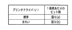
本実施形態では、図8に示すように、ホスト装置のプリンタドライバにユーザーが記録モードを選択可能な機能を用意し、プリンタドライバを介して選択された記録モードに応じて記録データ生成時の色毎(ノズル毎)のビット数を切り替える。 In the present embodiment, as shown in FIG. 8, the printer driver of the host device is provided with a function that allows the user to select the recording mode, and the color at the time of generating the recording data according to the recording mode selected via the printer driver. Switch the number of bits for each (nozzle).
具体的には、プリントドライバによって選択可能な記録モードを「標準」と「きれい」とする。「標準」モード選択時は、上記実施形態1のように、ドットの大きさが相対的に小さいもののデータ量(ビット量)を小さくする。一方、「きれい」モード選択時は、図6(b)に示したように、総てのドットに対し同じデータ量(ビット量)を割り当て、中、小ドットの出力階調数を3とする。 Specifically, the recording modes that can be selected by the print driver are “standard” and “pretty”. When the “standard” mode is selected, the data amount (bit amount) is reduced although the dot size is relatively small as in the first embodiment. On the other hand, when the “clean” mode is selected, as shown in FIG. 6B, the same data amount (bit amount) is assigned to all the dots, and the output gradation number of medium and small dots is set to 3. .
以上のように本実施形態によれば、記録モードの記録速度に応じてデータ量を変更するため、必要以上に画像品位や記録速度を低下することを回避することが可能となる。 As described above, according to the present embodiment, since the data amount is changed according to the recording speed in the recording mode, it is possible to avoid lowering the image quality and the recording speed more than necessary.
なお、本実施形態ではプリンタドライバにより選択可能な記録モードを2種類(「標準」と「きれい」)としているが、特にこれに限定されないことはもちろんである。例えば、選択可能な記録モードの種類は3種類以上であってもよい。本実施形態の意図する効果が得られる限りにおいて、例えばプリンタドライバで選択可能な記録用紙の種類や、用紙サイズによってデータ量を切り替えてもよい。 In this embodiment, there are two types of recording modes (“standard” and “pretty”) that can be selected by the printer driver. However, the present invention is not limited to this. For example, the number of selectable recording modes may be three or more. As long as the intended effect of the present embodiment can be obtained, the data amount may be switched depending on, for example, the type of recording paper that can be selected by the printer driver and the paper size.
(実施形態3)
図4に示した一連の画像処理を行うホスト装置(画像処理装置)210とインクジェットプリンタとは、図2のようにインターフェース211を介して接続される。近年のインクジェットプリンタでは多様化したインターフェース(以下、”I/F”とも記載する)の多くに対応するようになって来ている。代表的なI/Fとして、USB(Universal Serial Bus)のようなデータ転送速度が高速なI/Fから、比較的低速なIrDA、さらに低速なBT(BlueTooth)などがある。
(Embodiment 3)
The host device (image processing device) 210 that performs the series of image processing shown in FIG. 4 and the inkjet printer are connected via an
これらI/Fに関して、上記実施形態1、2を流用しそれらの実施形態と同様の効果を得ることが可能である。低速I/Fを実施形態2の「標準」、高速I/Fを「きれい」と置き換えて考え、低速のI/Fを用いるときは実施形態1のようにドットの大きさが相対的に小さいもののデータ量(ビット量)を小さくする。また、高速I/Fを用いるときは図6(b)のように総てのドットに対し同じデータ量(ビット量)を割り当てる。このように使用されているインターフェースの種類を判別し、インターフェースの種類に応じて生成する記録データのビット数を変えることにより、先の実施形態と同様の効果を得ることができる。 Regarding these I / Fs, the same effects as those of the embodiments can be obtained by diverting the first and second embodiments. Considering the low-speed I / F as “standard” in the second embodiment and the high-speed I / F as “clean”, when using a low-speed I / F, the dot size is relatively small as in the first embodiment. Reduce the data amount (bit amount) of things. When the high-speed I / F is used, the same data amount (bit amount) is assigned to all dots as shown in FIG. 6B. By discriminating the type of interface used in this way and changing the number of bits of recording data to be generated according to the type of interface, the same effect as in the previous embodiment can be obtained.
以上のように本実施形態によれば、第1のインターフェース(例えば、USB)よりも転送速度が遅い第2のインターフェース(例えば、BT)が使用されている場合、小ドット用記録データのビット数を大小ドット用記録データのビット数よりも小さくする。 As described above, according to the present embodiment, when the second interface (for example, BT) whose transfer speed is slower than that of the first interface (for example, USB) is used, the number of bits of the recording data for small dots. Is made smaller than the number of bits of the recording data for large and small dots.
また、I/Fに対するデータ生成方法の切り分けは、I/Fによって、特に無線系ではその接続状況によって転送レートが変動するなど、一概に転送レートを決定することができない場合がある。このような場合には、PC(ホストコンピュータ)からプリンタへダミーデータを転送し受信後PCへ情報を返却し、その時間から判定しデータ量をいずれで処理するのが最適化判断するなどの構成も効果的である。 In addition, the data generation method for the I / F may not be determined in general because the transfer rate varies depending on the I / F, particularly in the wireless system, depending on the connection status. In such a case, the dummy data is transferred from the PC (host computer) to the printer, the information is returned to the PC after reception, the determination is made based on the time, and the data amount is processed to determine the optimization. Is also effective.
(他の実施形態)
上記各実施形態に示す記録データ生成を含む画像処理は、ホスト装置において実行されるものであるが、本発明の実施形態がこれに限定されないことはもちろんである。プリンタなどの記録装置において実行されてもよく、特に本発明の一実施形態に係る量子化処理が記録装置において実行されてもよい。この場合、当該記録装置が画像処理装置を構成することになる。また、記録装置が画像処理装置として機能する場合、実施形態2で説明した記録モードの選択も記録装置側にて実行可能に構成するのが好ましい。
(Other embodiments)
The image processing including recording data generation shown in each of the above embodiments is executed in the host device, but it goes without saying that the embodiment of the present invention is not limited to this. The recording apparatus such as a printer may be executed. In particular, the quantization processing according to an embodiment of the present invention may be executed in the recording apparatus. In this case, the recording apparatus constitutes an image processing apparatus. When the recording apparatus functions as an image processing apparatus, it is preferable that the recording mode selection described in the second embodiment can be executed on the recording apparatus side.
また、上記各実施形態は、同じ色(同じ色相)で大きさが異なるドットを用いる場合について説明したが、本発明の実施形態はこれに限られない。同系色で色材濃度が異なるインク(いわゆる、濃淡インク、濃中淡インク)を用いて記録されるドット(つまり、同系色で濃度が異なるドット)を用いる場合についても、同様に本発明を適用できる。この場合、淡インクで記録される淡ドットのための記録データの1画素あたりのビット数を、濃インクで記録される濃ドットのための記録データの1画素あたりのビット数よりも小さく構成する。 Moreover, although each said embodiment demonstrated the case where the dot from which a magnitude | size differs with the same color (the same hue), embodiment of this invention is not restricted to this. The present invention is similarly applied to the case of using dots (that is, dots of the same color and different densities) recorded using inks of the same color and different color material densities (so-called dark and light inks, dark and medium light inks). it can. In this case, the number of bits per pixel of recording data for light dots recorded with light ink is configured to be smaller than the number of bits per pixel of recording data for dark dots recorded with dark ink. .
さらに、上記実施形態は総て図3に示した記録ヘッドを用いたプリンタに係るものである。しかし、特にこのヘッド構成に限るものではない。例えば図9(a)に示すように同色(同一色相)について少なくとも2つの異なる吐出量をもつ記録ヘッドを用いた記録装置であれば本発明を適用することができる。また、図9(b)のようなシアン、マゼンタ、イエローの5plが2列ずつあるような場合、各色2列を一つの色として処理しても、別のノズル列と処理してもよい。 Further, all of the above embodiments relate to a printer using the recording head shown in FIG. However, it is not particularly limited to this head configuration. For example, as shown in FIG. 9A, the present invention can be applied to any recording apparatus using recording heads having at least two different discharge amounts for the same color (same hue). Further, when there are two rows of cyan, magenta, and yellow 5pl as shown in FIG. 9B, the two rows of each color may be processed as one color or may be processed as another nozzle row.
以上の実施形態のように記録データ量を削減することは、ネットワーク上でプリンタを共有設定する場合にも、巨大なプリントデータが送信されるのは望ましくないのでこうした点に対しても効果的である。 Reducing the amount of recording data as in the above embodiment is effective for such a point because it is not desirable that huge print data is transmitted even when the printer is shared on the network. is there.
(さらに他の実施形態)
本発明は、上述した実施形態の機能を実現する、図4に示した一連の画像処理の一部に相当する量子化処理403を実現するプログラムコード、またはそれを記憶した記憶媒体によっても実現することができる。また、システムあるいは装置のコンピュータ(またはCPUやMPU)が記憶媒体に格納されたプログラムコードを読出し実行することによっても達成される。この場合、記憶媒体から読み出されたプログラムコード自体が前述した実施形態の機能を実現することになり、そのプログラムコードを記憶した記憶媒体は本発明を構成することになる。
(Still another embodiment)
The present invention is also realized by a program code for realizing the
プログラムコードを供給するための記憶媒体としては、例えば、フロッピー(登録商標)ディスク、ハードディスク、光ディスク、光磁気ディスク、CD−ROM、CD−R、磁気テープ、不揮発性のメモリカード、ROMなどを用いることができる。 As a storage medium for supplying the program code, for example, a floppy (registered trademark) disk, hard disk, optical disk, magneto-optical disk, CD-ROM, CD-R, magnetic tape, nonvolatile memory card, ROM, or the like is used. be able to.
また、コンピュータが読み出したプログラムコードを実行することにより、前述した実施形態の機能が実現されるだけでなく、そのプログラムコードの指示に基づき、コンピュータ上で稼動しているOSが実際の処理の一部または全部を行うものであってもよい。 In addition, by executing the program code read by the computer, not only the functions of the above-described embodiments are realized, but also the OS running on the computer performs an actual process based on the instruction of the program code. Part or all may be performed.
更に、プログラムコードが、コンピュータに挿入された機能拡張ボードやコンピュータに接続された機能拡張ユニットに備わるメモリに書き込まれた後、そのプログラムコードの指示に基づき、CPUなどが実際の処理の一部または全部を行うものであってもよい。 Further, after the program code is written in a memory provided in a function expansion board inserted into the computer or a function expansion unit connected to the computer, the CPU or the like may perform part of the actual processing or based on the instruction of the program code. You may do everything.
1 インクジェットプリンタ
3 記録ヘッド
200 コントローラ
201 MPU
202 ROM
204 RAM
210 ホスト装置
DESCRIPTION OF
202 ROM
204 RAM
210 Host device
Claims (11)
第1ドットを記録するための第1の記録データと、前記第1ドットと同色で前記第1ドットよりも小さい第2ドットを記録するための第2の記録データを生成するための生成手段を有し、
前記第2の記録データの1画素あたりのビット数は、前記第1の記録データの1画素あたりのビット数よりも小さいことを特徴とする画像処理装置。 (Large, small number of bits <large number of bits)
Generation means for generating first recording data for recording the first dots and second recording data for recording the second dots having the same color as the first dots and smaller than the first dots. Have
The image processing apparatus according to claim 1, wherein the number of bits per pixel of the second recording data is smaller than the number of bits per pixel of the first recording data.
前記生成手段は、更に、前記第2ドットと同色で前記第2ドットより小さい第3ドットを記録するための第3の記録データを生成することが可能であり、
前記第3の記録データの1画素あたりのビット数は、前記第2の記録データの1画素あたりのビット数と同じであることを特徴とする請求項1に記載の画像処理装置。 (Large, medium and small, small bit number = medium bit number)
The generating means can further generate third recording data for recording a third dot having the same color as the second dot and smaller than the second dot,
The image processing apparatus according to claim 1, wherein the number of bits per pixel of the third recording data is the same as the number of bits per pixel of the second recording data.
前記生成手段は、更に、前記第2ドットと同色で前記第2ドットより小さい第3ドットを記録するための第3の記録データを生成することが可能であり、
前記第3の記録データの1画素あたりのビット数は、前記第2の記録データの1画素あたりのビット数よりも小さいであることを特徴とする請求項1に記載の画像処理装置。 (Large, medium and small, small bit number <middle bit number)
The generating means can further generate third recording data for recording a third dot having the same color as the second dot and smaller than the second dot,
The image processing apparatus according to claim 1, wherein the number of bits per pixel of the third recording data is smaller than the number of bits per pixel of the second recording data.
第1ドットを記録するための第1の記録データと、前記第1ドットと同系色で前記第1ドットよりも濃度の低い第2ドットを記録するための第2の記録データを生成するための生成手段を有し、
前記第2の記録データの1画素あたりのビット数は、前記第1の記録データの1画素あたりのビット数よりも小さいことを特徴とする画像処理装置。 (Dark, light bit number <dark bit number)
First recording data for recording the first dot and second recording data for recording the second dot having the same color as the first dot and having a lower density than the first dot Generating means,
The image processing apparatus according to claim 1, wherein the number of bits per pixel of the second recording data is smaller than the number of bits per pixel of the first recording data.
前記生成手段は、N(Nは3以上の整数)ビットの記録データをNよりも小さいM(Mは1以上の整数)ビットの記録データに変換する処理によって前記記録データの生成を行うことを特徴とする請求項1ないし4のいずれかに記載の画像処理装置。 (Quantization)
The generating means generates the recording data by a process of converting recording data of N (N is an integer of 3 or more) bits into recording data of M (M is an integer of 1 or more) bits smaller than N. The image processing apparatus according to claim 1, wherein the image processing apparatus is an image processing apparatus.
前記第2の記録データに基づいて前記1画素あたりに記録される最大ドット数は、前記第1の記録データに基づいて前記1画素あたりに記録される最大ドット数よりも少ないことを特徴とする請求項1ないし5のいずれかに記載の画像処理装置。 (Number of gradations)
The maximum number of dots recorded per pixel based on the second recording data is smaller than the maximum number of dots recorded per pixel based on the first recording data. The image processing apparatus according to claim 1.
第1の記録モードと前記第1の記録モードよりも記録動作が速い第2の記録モードを含む複数の記録モードの中から、実行する記録モードを選択可能な手段を更に備え、
前記生成手段は、前記第2の記録モードが選択された場合、前記第1の記録データのビット数よりも小さいビット数を有する前記第2の記録データを生成し、前記第1の記録モードが選択された場合、前記第1の記録データのビット数と同じビット数を有する前記第2の記録データを生成することを特徴とする請求項1ないし6のいずれかに記載の画像処理装置。 (High-speed recording mode)
Means for selecting a recording mode to be executed from a plurality of recording modes including a first recording mode and a second recording mode in which a recording operation is faster than the first recording mode;
When the second recording mode is selected, the generation unit generates the second recording data having a bit number smaller than the number of bits of the first recording data, and the first recording mode is The image processing apparatus according to claim 1, wherein when selected, the second recording data having the same number of bits as the number of bits of the first recording data is generated.
前記画像処理装置は、前記第1の記録データに基づき前記第1ドットを記録可能で、且つ前記第2の記録データに基づき前記第2ドットを記録可能である記録装置に対してインターフェースを介して接続されており、
第1のインターフェースよりも転送低速が遅い第2のインターフェースが使用されている場合、前記生成手段は、前記第1の記録データのビット数よりも小さいビット数を有する前記第2の記録データを生成することを特徴とする請求項1ないし6のいずれかに記載の画像処理装置。 (Low speed interface)
The image processing apparatus is capable of recording the first dot based on the first recording data and is capable of recording the second dot based on the second recording data via an interface. Connected,
When the second interface whose transfer speed is slower than that of the first interface is used, the generation unit generates the second recording data having a bit number smaller than the bit number of the first recording data. The image processing apparatus according to claim 1, wherein the image processing apparatus is an image processing apparatus.
第1ドットと前記第1ドットと同色で前記第1ドットよりも小さい第2ドットを記録可能な画像記録装置であって、
第1ドットを記録するための第1の記録データに基づいて前記第1ドットを記録し、前記第1ドットと同色で前記第1ドットよりも小さい第2ドットを記録するための第2の記録データに基づいて前記第2ドットを記録する手段を有し、
前記第2の記録データの1画素あたりのビット数は、前記第1の記録データの1画素あたりのビット数よりも小さいことを特徴とする画像記録装置。 (Printer)
An image recording apparatus capable of recording a second dot having the same color as the first dot and smaller than the first dot,
Second recording for recording the first dot based on first recording data for recording the first dot, and recording a second dot having the same color as the first dot and smaller than the first dot. Means for recording the second dot based on the data;
The image recording apparatus according to claim 1, wherein the number of bits per pixel of the second recording data is smaller than the number of bits per pixel of the first recording data.
第1ドットを記録するための第1の記録データと、前記第1ドットと同色で前記第1ドットよりも小さい第2ドットを記録するための第2の記録データを生成するための生成工程を有し、
前記第2の記録データの1画素あたりのビット数は、前記第1の記録データの1画素あたりのビット数よりも小さいことを特徴とする記録データ生成方法。 (Data generation method)
A generation process for generating first recording data for recording the first dots and second recording data for recording the second dots having the same color as the first dots and smaller than the first dots. Have
The recording data generation method, wherein the number of bits per pixel of the second recording data is smaller than the number of bits per pixel of the first recording data.
コンピュータプログラムであって、
第1ドットを記録するための第1の記録データの1画素あたりのビット数が、前記第1ドットと同色で前記第1ドットよりも小さい第2ドットを記録するための第2の記録データの1画素あたりのビット数よりも多くなるように、前記第1の記録データと前記第2の記録データを生成する処理を実行させる機能
をコンピュータに実現させるためのコンピュータプログラム。
(program)
A computer program,
In the second recording data for recording the second dot, the number of bits per pixel of the first recording data for recording the first dot is the same color as the first dot and smaller than the first dot. A computer program for causing a computer to realize a function of executing processing for generating the first recording data and the second recording data so as to be larger than the number of bits per pixel.
Priority Applications (2)
| Application Number | Priority Date | Filing Date | Title |
|---|---|---|---|
| JP2006227179A JP2008049563A (en) | 2006-08-23 | 2006-08-23 | Image processor, image recorder and recording data forming method |
| US11/841,160 US8711424B2 (en) | 2006-08-23 | 2007-08-20 | Image processing apparatus, image printing apparatus and printing data generation method |
Applications Claiming Priority (1)
| Application Number | Priority Date | Filing Date | Title |
|---|---|---|---|
| JP2006227179A JP2008049563A (en) | 2006-08-23 | 2006-08-23 | Image processor, image recorder and recording data forming method |
Related Child Applications (1)
| Application Number | Title | Priority Date | Filing Date |
|---|---|---|---|
| JP2011131603A Division JP2011207230A (en) | 2011-06-13 | 2011-06-13 | Image processing apparatus and method for generating record data |
Publications (2)
| Publication Number | Publication Date |
|---|---|
| JP2008049563A true JP2008049563A (en) | 2008-03-06 |
| JP2008049563A5 JP2008049563A5 (en) | 2008-12-18 |
Family
ID=39113085
Family Applications (1)
| Application Number | Title | Priority Date | Filing Date |
|---|---|---|---|
| JP2006227179A Pending JP2008049563A (en) | 2006-08-23 | 2006-08-23 | Image processor, image recorder and recording data forming method |
Country Status (2)
| Country | Link |
|---|---|
| US (1) | US8711424B2 (en) |
| JP (1) | JP2008049563A (en) |
Cited By (1)
| Publication number | Priority date | Publication date | Assignee | Title |
|---|---|---|---|---|
| JP5490128B2 (en) * | 2009-09-30 | 2014-05-14 | キヤノン株式会社 | Inkjet head |
Families Citing this family (1)
| Publication number | Priority date | Publication date | Assignee | Title |
|---|---|---|---|---|
| JP5913887B2 (en) * | 2011-09-30 | 2016-04-27 | 株式会社Screenホールディングス | Inkjet printer and image recording method |
Citations (8)
| Publication number | Priority date | Publication date | Assignee | Title |
|---|---|---|---|---|
| JPH1016251A (en) * | 1996-06-28 | 1998-01-20 | Canon Inc | Method and apparatus for ink-jet recording |
| JP2000118008A (en) * | 1998-10-14 | 2000-04-25 | Seiko Epson Corp | Printing apparatus, printing method, and recording medium |
| JP2002301815A (en) * | 2001-01-31 | 2002-10-15 | Canon Inc | Recorder and method of creating recording data |
| JP2004098468A (en) * | 2002-09-09 | 2004-04-02 | Canon Inc | Color output method and color output unit |
| JP2004098467A (en) * | 2002-09-09 | 2004-04-02 | Canon Inc | Inkjet recording head |
| JP2005169754A (en) * | 2003-12-09 | 2005-06-30 | Canon Inc | Ink jet recorder and ink jet recording method |
| JP2005219287A (en) * | 2004-02-04 | 2005-08-18 | Seiko Epson Corp | Print control apparatus, computer program, and dot formation method |
| JP2005238661A (en) * | 2004-01-29 | 2005-09-08 | Canon Inc | Recording apparatus, recording system, and control method for recording apparatus |
Family Cites Families (17)
| Publication number | Priority date | Publication date | Assignee | Title |
|---|---|---|---|---|
| DE4332609A1 (en) * | 1993-09-24 | 1995-03-30 | Esselte Meto Int Gmbh | Circuit arrangement for data input and output for a printer |
| JPH07304213A (en) * | 1994-05-11 | 1995-11-21 | Canon Inc | Printer and control method thereof |
| JP3919874B2 (en) * | 1996-04-05 | 2007-05-30 | セイコーエプソン株式会社 | Inkjet recording device with high-speed printing mode |
| JPH103509A (en) * | 1996-06-17 | 1998-01-06 | Olympus Optical Co Ltd | Device for recording information and method therefor |
| US6161919A (en) * | 1999-02-22 | 2000-12-19 | Xerox Corporation | Ink coverage reduction method for printers capable of printing multiple drop sizes |
| JP2000253247A (en) | 1999-02-26 | 2000-09-14 | Seiko Epson Corp | Data conversion device, data conversion method, and printing device using the same |
| JP3925018B2 (en) | 1999-11-26 | 2007-06-06 | セイコーエプソン株式会社 | Printing control apparatus, printing apparatus, printing control method, and recording medium |
| JP3601491B2 (en) * | 2000-10-06 | 2004-12-15 | セイコーエプソン株式会社 | Image processing apparatus, image processing method, recording medium, and program |
| JP2002171392A (en) | 2000-12-01 | 2002-06-14 | Seiko Epson Corp | Image processing apparatus, print control apparatus, image processing method, and recording medium |
| US6877833B2 (en) * | 2001-01-31 | 2005-04-12 | Canon Kabushiki Kaisha | Printing data producing method for printing apparatus |
| JP4266588B2 (en) * | 2002-07-30 | 2009-05-20 | キヤノン株式会社 | Recording apparatus and recording control method |
| US6702425B1 (en) * | 2002-09-23 | 2004-03-09 | Eastman Kodak Company | Coalescence-free inkjet printing by controlling drop spreading on/in a receiver |
| US7126724B2 (en) * | 2003-03-11 | 2006-10-24 | Kodak Graphic Communications Canada Company | Flexographic printing |
| US6866365B1 (en) * | 2004-04-01 | 2005-03-15 | Eastman Kodak Company | Bi-directional color printer and method of printing |
| JP4307319B2 (en) * | 2004-04-30 | 2009-08-05 | キヤノン株式会社 | Recording apparatus and recording method |
| US7413272B2 (en) * | 2004-11-04 | 2008-08-19 | Applied Materials, Inc. | Methods and apparatus for precision control of print head assemblies |
| US7134328B2 (en) * | 2004-11-10 | 2006-11-14 | Seiko Epson Corporation | Liquid-ejection testing method, liquid-ejection testing device, and computer-readable medium |
-
2006
- 2006-08-23 JP JP2006227179A patent/JP2008049563A/en active Pending
-
2007
- 2007-08-20 US US11/841,160 patent/US8711424B2/en not_active Expired - Fee Related
Patent Citations (8)
| Publication number | Priority date | Publication date | Assignee | Title |
|---|---|---|---|---|
| JPH1016251A (en) * | 1996-06-28 | 1998-01-20 | Canon Inc | Method and apparatus for ink-jet recording |
| JP2000118008A (en) * | 1998-10-14 | 2000-04-25 | Seiko Epson Corp | Printing apparatus, printing method, and recording medium |
| JP2002301815A (en) * | 2001-01-31 | 2002-10-15 | Canon Inc | Recorder and method of creating recording data |
| JP2004098468A (en) * | 2002-09-09 | 2004-04-02 | Canon Inc | Color output method and color output unit |
| JP2004098467A (en) * | 2002-09-09 | 2004-04-02 | Canon Inc | Inkjet recording head |
| JP2005169754A (en) * | 2003-12-09 | 2005-06-30 | Canon Inc | Ink jet recorder and ink jet recording method |
| JP2005238661A (en) * | 2004-01-29 | 2005-09-08 | Canon Inc | Recording apparatus, recording system, and control method for recording apparatus |
| JP2005219287A (en) * | 2004-02-04 | 2005-08-18 | Seiko Epson Corp | Print control apparatus, computer program, and dot formation method |
Cited By (1)
| Publication number | Priority date | Publication date | Assignee | Title |
|---|---|---|---|---|
| JP5490128B2 (en) * | 2009-09-30 | 2014-05-14 | キヤノン株式会社 | Inkjet head |
Also Published As
| Publication number | Publication date |
|---|---|
| US20080049237A1 (en) | 2008-02-28 |
| US8711424B2 (en) | 2014-04-29 |
Similar Documents
| Publication | Publication Date | Title |
|---|---|---|
| US8118388B2 (en) | Adjustment of misalignments of recording positions during bidirectional printing | |
| US8622501B2 (en) | Inkjet printer and inkjet printing method | |
| US6846066B2 (en) | Recording apparatus for recording image by expanding the image in dot pattern | |
| JP2005169754A (en) | Ink jet recorder and ink jet recording method | |
| JP4560193B2 (en) | Data processing method and data processing apparatus | |
| US7350893B2 (en) | Inkjet printing method | |
| JP4412713B2 (en) | RECORDING DEVICE, RECORDING SYSTEM, AND RECORDING DEVICE CONTROL METHOD | |
| JP2006001051A (en) | Inkjet recording method and inkjet recorder | |
| JP4497807B2 (en) | Recording apparatus and method for controlling the apparatus | |
| JP2004167818A (en) | Recording method | |
| JP4387721B2 (en) | Recording apparatus and recording method | |
| US7641309B2 (en) | Data processing apparatus, data processing method, ink jet printing apparatus, and ink jet printing method | |
| US7441858B2 (en) | Printing method, printing system, and storage medium having program stored thereon | |
| JP2008049563A (en) | Image processor, image recorder and recording data forming method | |
| US20120194594A1 (en) | Inkjet printing apparatus and inkjet printing method | |
| JP2011076156A (en) | Apparatus and method for processing image | |
| US7481514B2 (en) | Printing method, control method, printing apparatus, control apparatus, and computer-readable storage medium | |
| JP5072350B2 (en) | Image forming apparatus and control method thereof | |
| JP2011207230A (en) | Image processing apparatus and method for generating record data | |
| US7672015B2 (en) | Printing method and system for converting color tones to lighter and darker values for printing with light and dark inks | |
| JP2004338215A (en) | Printer | |
| JP2009101667A (en) | Recording device and control method of recording device | |
| JP2006224616A (en) | Recording method and recording system | |
| JP2024006190A (en) | Recording device and method for recording | |
| JP5343504B2 (en) | Inkjet recording apparatus, image forming system, image forming method, and program |
Legal Events
| Date | Code | Title | Description |
|---|---|---|---|
| A521 | Request for written amendment filed |
Free format text: JAPANESE INTERMEDIATE CODE: A523 Effective date: 20081031 |
|
| A621 | Written request for application examination |
Free format text: JAPANESE INTERMEDIATE CODE: A621 Effective date: 20081031 |
|
| A977 | Report on retrieval |
Free format text: JAPANESE INTERMEDIATE CODE: A971007 Effective date: 20100930 |
|
| A131 | Notification of reasons for refusal |
Free format text: JAPANESE INTERMEDIATE CODE: A131 Effective date: 20101005 |
|
| RD02 | Notification of acceptance of power of attorney |
Free format text: JAPANESE INTERMEDIATE CODE: A7422 Effective date: 20101106 |
|
| A521 | Request for written amendment filed |
Free format text: JAPANESE INTERMEDIATE CODE: A523 Effective date: 20101206 |
|
| A02 | Decision of refusal |
Free format text: JAPANESE INTERMEDIATE CODE: A02 Effective date: 20110311 |
|
| A521 | Request for written amendment filed |
Free format text: JAPANESE INTERMEDIATE CODE: A523 Effective date: 20110613 |