JP2007518446A - Surgical fasteners and surgical fixation devices - Google Patents
Surgical fasteners and surgical fixation devices Download PDFInfo
- Publication number
- JP2007518446A JP2007518446A JP2006520100A JP2006520100A JP2007518446A JP 2007518446 A JP2007518446 A JP 2007518446A JP 2006520100 A JP2006520100 A JP 2006520100A JP 2006520100 A JP2006520100 A JP 2006520100A JP 2007518446 A JP2007518446 A JP 2007518446A
- Authority
- JP
- Japan
- Prior art keywords
- surgical
- fastener
- thread
- fixation device
- surgical fixation
- Prior art date
- Legal status (The legal status is an assumption and is not a legal conclusion. Google has not performed a legal analysis and makes no representation as to the accuracy of the status listed.)
- Pending
Links
Images


Classifications
-
- A—HUMAN NECESSITIES
- A61—MEDICAL OR VETERINARY SCIENCE; HYGIENE
- A61B—DIAGNOSIS; SURGERY; IDENTIFICATION
- A61B17/00—Surgical instruments, devices or methods
- A61B17/04—Surgical instruments, devices or methods for suturing wounds; Holders or packages for needles or suture materials
- A61B17/0401—Suture anchors, buttons or pledgets, i.e. means for attaching sutures to bone, cartilage or soft tissue; Instruments for applying or removing suture anchors
-
- A—HUMAN NECESSITIES
- A61—MEDICAL OR VETERINARY SCIENCE; HYGIENE
- A61B—DIAGNOSIS; SURGERY; IDENTIFICATION
- A61B17/00—Surgical instruments, devices or methods
- A61B17/04—Surgical instruments, devices or methods for suturing wounds; Holders or packages for needles or suture materials
- A61B17/06—Needles ; Sutures; Needle-suture combinations; Holders or packages for needles or suture materials
- A61B17/06166—Sutures
-
- A—HUMAN NECESSITIES
- A61—MEDICAL OR VETERINARY SCIENCE; HYGIENE
- A61B—DIAGNOSIS; SURGERY; IDENTIFICATION
- A61B17/00—Surgical instruments, devices or methods
- A61B17/068—Surgical staplers, e.g. containing multiple staples or clamps
-
- A—HUMAN NECESSITIES
- A61—MEDICAL OR VETERINARY SCIENCE; HYGIENE
- A61B—DIAGNOSIS; SURGERY; IDENTIFICATION
- A61B17/00—Surgical instruments, devices or methods
- A61B17/12—Surgical instruments, devices or methods for ligaturing or otherwise compressing tubular parts of the body, e.g. blood vessels or umbilical cord
- A61B17/122—Clamps or clips, e.g. for the umbilical cord
- A61B17/1222—Packages or dispensers therefor
-
- A—HUMAN NECESSITIES
- A61—MEDICAL OR VETERINARY SCIENCE; HYGIENE
- A61B—DIAGNOSIS; SURGERY; IDENTIFICATION
- A61B17/00—Surgical instruments, devices or methods
- A61B2017/00743—Type of operation; Specification of treatment sites
- A61B2017/00805—Treatment of female stress urinary incontinence
-
- A—HUMAN NECESSITIES
- A61—MEDICAL OR VETERINARY SCIENCE; HYGIENE
- A61B—DIAGNOSIS; SURGERY; IDENTIFICATION
- A61B17/00—Surgical instruments, devices or methods
- A61B17/04—Surgical instruments, devices or methods for suturing wounds; Holders or packages for needles or suture materials
- A61B17/0401—Suture anchors, buttons or pledgets, i.e. means for attaching sutures to bone, cartilage or soft tissue; Instruments for applying or removing suture anchors
- A61B2017/0409—Instruments for applying suture anchors
-
- A—HUMAN NECESSITIES
- A61—MEDICAL OR VETERINARY SCIENCE; HYGIENE
- A61B—DIAGNOSIS; SURGERY; IDENTIFICATION
- A61B17/00—Surgical instruments, devices or methods
- A61B17/04—Surgical instruments, devices or methods for suturing wounds; Holders or packages for needles or suture materials
- A61B17/0401—Suture anchors, buttons or pledgets, i.e. means for attaching sutures to bone, cartilage or soft tissue; Instruments for applying or removing suture anchors
- A61B2017/0417—T-fasteners
-
- A—HUMAN NECESSITIES
- A61—MEDICAL OR VETERINARY SCIENCE; HYGIENE
- A61B—DIAGNOSIS; SURGERY; IDENTIFICATION
- A61B17/00—Surgical instruments, devices or methods
- A61B17/04—Surgical instruments, devices or methods for suturing wounds; Holders or packages for needles or suture materials
- A61B17/0401—Suture anchors, buttons or pledgets, i.e. means for attaching sutures to bone, cartilage or soft tissue; Instruments for applying or removing suture anchors
- A61B2017/044—Suture anchors, buttons or pledgets, i.e. means for attaching sutures to bone, cartilage or soft tissue; Instruments for applying or removing suture anchors with a threaded shaft, e.g. screws
- A61B2017/0441—Suture anchors, buttons or pledgets, i.e. means for attaching sutures to bone, cartilage or soft tissue; Instruments for applying or removing suture anchors with a threaded shaft, e.g. screws the shaft being a rigid coil or spiral
-
- A—HUMAN NECESSITIES
- A61—MEDICAL OR VETERINARY SCIENCE; HYGIENE
- A61B—DIAGNOSIS; SURGERY; IDENTIFICATION
- A61B17/00—Surgical instruments, devices or methods
- A61B17/064—Surgical staples, i.e. penetrating the tissue
- A61B2017/0649—Coils or spirals
-
- A—HUMAN NECESSITIES
- A61—MEDICAL OR VETERINARY SCIENCE; HYGIENE
- A61F—FILTERS IMPLANTABLE INTO BLOOD VESSELS; PROSTHESES; DEVICES PROVIDING PATENCY TO, OR PREVENTING COLLAPSING OF, TUBULAR STRUCTURES OF THE BODY, e.g. STENTS; ORTHOPAEDIC, NURSING OR CONTRACEPTIVE DEVICES; FOMENTATION; TREATMENT OR PROTECTION OF EYES OR EARS; BANDAGES, DRESSINGS OR ABSORBENT PADS; FIRST-AID KITS
- A61F2/00—Filters implantable into blood vessels; Prostheses, i.e. artificial substitutes or replacements for parts of the body; Appliances for connecting them with the body; Devices providing patency to, or preventing collapsing of, tubular structures of the body, e.g. stents
- A61F2/0004—Closure means for urethra or rectum, i.e. anti-incontinence devices or support slings against pelvic prolapse
- A61F2/0031—Closure means for urethra or rectum, i.e. anti-incontinence devices or support slings against pelvic prolapse for constricting the lumen; Support slings for the urethra
- A61F2/0036—Closure means for urethra or rectum, i.e. anti-incontinence devices or support slings against pelvic prolapse for constricting the lumen; Support slings for the urethra implantable
- A61F2/0045—Support slings
Landscapes
- Health & Medical Sciences (AREA)
- Surgery (AREA)
- Life Sciences & Earth Sciences (AREA)
- Biomedical Technology (AREA)
- Nuclear Medicine, Radiotherapy & Molecular Imaging (AREA)
- Engineering & Computer Science (AREA)
- Heart & Thoracic Surgery (AREA)
- Medical Informatics (AREA)
- Molecular Biology (AREA)
- Animal Behavior & Ethology (AREA)
- General Health & Medical Sciences (AREA)
- Public Health (AREA)
- Veterinary Medicine (AREA)
- Rheumatology (AREA)
- Surgical Instruments (AREA)
Abstract
外科用細糸を生体組織に固定する外科用固定装置(100)。同装置は把持ハンドル(107)と、前記把持ハンドルから延在する細長いシャフト(102)とを含む。隔室(63)は1つ以上の外科用ファスナを収容する。排出機構は、1つ以上の外科用ファスナを収容する隔室から外科用ファスナを排出するために使用される。同装置はまた、ファスナがシャフトから排出される時に細糸をつかめるようシャフトに沿って外科用細糸(109)を分配する細糸分配システム(108)を含む。本発明はまた、同装置で使用する外科用ファスナと外科用細糸とを提供する。
【選択図】 図14
Surgical fixation device (100) for fixing surgical thread to biological tissue. The apparatus includes a grip handle (107) and an elongated shaft (102) extending from the grip handle. The compartment (63) houses one or more surgical fasteners. The evacuation mechanism is used to evacuate the surgical fastener from a compartment that houses one or more surgical fasteners. The apparatus also includes a thread dispensing system (108) that distributes the surgical thread (109) along the shaft so that the thread can be grasped as the fastener is ejected from the shaft. The present invention also provides a surgical fastener and surgical thread for use with the same device.
[Selection] FIG.
Description
本発明は外科用ファスナと外科用固定装置とに関する。 The present invention relates to surgical fasteners and surgical fixation devices.
従来の外科用ファスナは通常の金属製ステープルの形をとっており、送出装置によってこれを曲げることにより生体組織をつなぎ合わせる。これらのステープルは、直線形または弓形の冠部によって一端がつなぎ合わされた、1対の脚もしくは枝を備えている。 Conventional surgical fasteners are in the form of conventional metal staples that are joined together by bending them with a delivery device. These staples have a pair of legs or branches joined at one end by a straight or arcuate crown.
現在、内視鏡処置や開放式処置で組織同士を取り付けるため、あるいは組織にメッシュパッチを取り付けるため、様々な外科用ファスナと固定装置を利用できる。そのような外科用ファスナのひとつに、外科用ステープラ、すなわちクリップアプリケータがある。このステープラでは、複数の未形成ステープルが、またはスタック状に積み重ねられた未形成ステープルが、カートリッジの中に収容されており、スプリング機構により器具の中で連続的に前進させられる、または給送される。スタックから最遠位のステープルを分離し、さらにこの最遠位のステープルをステープル閉鎖機構の中へ給送するため、2次給送機構が使われている。そのような機構は、米国特許第5,470,010号及び米国特許第5,582,616号に見られる。 Currently, a variety of surgical fasteners and fixation devices are available for attaching tissues to each other in endoscopic and open procedures, or for attaching mesh patches to tissues. One such surgical fastener is a surgical stapler or clip applicator. In this stapler, a plurality of unformed staples or unformed staples stacked in a stack are accommodated in a cartridge, and are continuously advanced or fed in an instrument by a spring mechanism. The A secondary feeding mechanism is used to separate the distal-most staple from the stack and feed the distal-most staple into the staple closing mechanism. Such a mechanism is found in US Pat. No. 5,470,010 and US Pat. No. 5,582,616.
一部の応用では、2つの相対する方向から生体組織に到達でき、生体組織を通過した後のステープルの脚をアンビルを用いて変形することがある。1方向からのみ生体組織に到達する応用では、生体組織の中で脚が互いに向かって突出することにより生体組織の中でステープルを保持するよう、従来型ステープルの冠部をアンビルで変形することがある。 In some applications, the living tissue can be reached from two opposite directions, and the leg of the staple after passing through the living tissue may be deformed using an anvil. In applications that reach the living tissue from only one direction, the crown of the conventional staple can be deformed with an anvil so that the legs protrude toward each other in the living tissue to hold the staple in the living tissue. is there.
主にメッシュを組織に取り付けるために使われるもうひとつのステープラ機構では、アンビルを使用しない。代わりに、組織同士をつなぎ、ポリプロピレンあるいは同様の材料のメッシュまたはその他のパッチを組織に取り付けるため、螺旋状のワイヤを備えるファスナを組織の中にねじ込む、または回し込む。米国特許第5,582,616号、米国特許第5,810,882号、及び米国特許第5,830,221号には、この種の器具とファスナとが見られる。アンビルを必要としないもうひとつのタイプのファスナでは、ニチノル(Nitinol(登録商標))等の形状記憶合金でできたファスナを適用する。これらのファスナは主に、補綴材や人工メッシュを組織に固定するために使用する。 Another stapler mechanism, mainly used to attach the mesh to the tissue, does not use an anvil. Instead, a fastener with a helical wire is screwed or turned into the tissue to connect the tissues and attach a mesh or other patch of polypropylene or similar material to the tissue. U.S. Pat. No. 5,582,616, U.S. Pat. No. 5,810,882, and U.S. Pat. No. 5,830,221 show such instruments and fasteners. Another type of fastener that does not require an anvil applies a fastener made of a shape memory alloy such as Nitinol (registered trademark). These fasteners are primarily used to secure prosthetics and artificial meshes to tissue.
上記の器具では、器具の細長いシャフトの中に配置された機構によって、ステープルまたはアンカーのスタックが同シャフトの遠位末端まで押され、ステープルは遠位末端から排出される。この機構は、シャフトの直径が同機構を収容するための所要最小直径を下回ることを防ぐ。これらの装置で達成できる最小シャフト直径は、一部の腹腔鏡及び低侵襲的処置の効率を制限することがある。 In the instrument described above, a mechanism disposed within the elongated shaft of the instrument pushes the stack of staples or anchors to the distal end of the shaft, and the staple is ejected from the distal end. This mechanism prevents the shaft diameter from falling below the minimum required diameter to accommodate the mechanism. The minimum shaft diameter that can be achieved with these devices may limit the efficiency of some laparoscopic and minimally invasive procedures.
本発明はこれの第1の態様において、外科用固定装置を提供する。本書で用いる語句「外科用固定装置」は、外科用ファスナを生体組織の中へ挿入する任意の外科用装置を指し、外科用ステープラと外科用接合具を含む。本書で用いる語句「外科用ファスナ」は、生体組織の中へ挿入され定着するよう構成された任意の装置を指し、例えば外科用ステープル、外科用ピン、外科用アンカー、外科用矢、あるいは2つの組織をつなぎ合わせるため、または合成装置を生体組織に取り付けるために用いる、その他のタイプのファスナを含む。 The present invention, in a first aspect thereof, provides a surgical fixation device. As used herein, the phrase “surgical fixation device” refers to any surgical device that inserts a surgical fastener into living tissue and includes a surgical stapler and a surgical joint. As used herein, the phrase “surgical fastener” refers to any device configured to be inserted and anchored into living tissue, such as a surgical staple, a surgical pin, a surgical anchor, a surgical arrow, or two Other types of fasteners are used to stitch tissue together or to attach a synthesizer to living tissue.
本発明の外科用ファスナには一定量の外科用細糸が設けられる。ファスナは、体腔の中へ挿入され、外科用ファスナを排出し、体腔内の第1の位置で外科用細糸片の一端を生体組織に固定するよう構成されている。次に固定装置を体腔内の第2の位置まで移し、固定装置から第2のファスナを排出し、体腔内の第2の位置で細糸沿いの別地点を生体組織に固定することもできる。こうして生体組織の第1の位置と第2の位置とが、細糸の1分節によって互いに結ばれる。固定装置はさらに、細糸を切断することにより、各末端にて第1及び第2の位置に固定された細糸片を解放するよう構成されている。 The surgical fastener of the present invention is provided with a certain amount of surgical thread. The fastener is configured to be inserted into the body cavity, eject the surgical fastener, and secure one end of the surgical thread piece to the living tissue at a first location within the body cavity. The fixation device can then be moved to a second position in the body cavity, the second fastener can be ejected from the fixation device, and another point along the filament can be fixed to the living tissue at the second position in the body cavity. Thus, the first position and the second position of the living tissue are connected to each other by one segment of the fine thread. The anchoring device is further configured to release the thread strips secured at the first and second positions at each end by cutting the thread.
本書で用いる用語「外科用細糸」は、任意の断面形状を有し、且つ生体適合性材料でできた細糸を指す。細糸は、リボン、帯、または細片等、矩形の断面を有することもあれば、コード、より糸、またはワイヤ等、円形の断面を有することもある。細糸はまた中空の円筒であってもよい。細糸は完全であってもよく、あるいはこれの中に穿孔を有することもある。細糸はまたメッシュであってもよく、あるいはネットであってもよい。細糸は生体分解性であってもよく、あるいは非生体分解性であってもよい。 As used herein, the term “surgical thread” refers to a thread having any cross-sectional shape and made of a biocompatible material. The fine thread may have a rectangular cross section, such as a ribbon, band, or strip, or it may have a circular cross section, such as a cord, strand, or wire. The fine thread may also be a hollow cylinder. The yarn may be complete or may have perforations therein. The fine thread may also be a mesh or a net. The fine yarn may be biodegradable or non-biodegradable.
本発明の装置は、体腔の中で器官を配置するため、あるいは細糸の格子を形成して生体組織を支えるため、1つ以上の外科用細糸片を体腔の中へ取り付けるのに使用できるであろう。 The device of the present invention can be used to place one or more surgical thread pieces into a body cavity to place an organ within a body cavity or to form a lattice of filaments to support living tissue. Will.
本発明はこれの第2の態様において、本発明の外科用ファスナで使用する外科用ファスナを提供する。 The present invention, in a second aspect thereof, provides a surgical fastener for use with the surgical fastener of the present invention.
本発明はこれの第3の態様において、本発明の外科用ファスナで使用する外科用細糸を提供する。
例えば鼠径ヘルニアの腹腔鏡式修復なら、本発明の固定装置を用いて1つのポートのみを使用して遂行できるであろう。腹壁の欠陥は、適度の張力により組織に取り付けられた細糸を用いて閉ざすことにより、再発を防ぐことができる。そのアプローチは切開バルーンを使用する腹膜前式でよく、細糸片を使って内側から腹壁の欠陥を閉じる格子状の構造を細糸片から作り、これを組織に取り付ける。あるいは代わりに、小さい皮膚切開を通じて内視鏡的にヘルニア修復を行うこともできるであろう。外側から欠陥を閉じ、次に鼠径管の後壁の上にバルーンを挿入してスペースを作る。鼠径管の後壁の衰弱は組織に取り付けられた細糸で閉じられる。これは、開放式リヒテンシュタインメッシュヘルニア修復術を内視鏡的に再現する処置であり、局所麻酔で遂行できるであろう。
The present invention, in its third aspect, provides a surgical thread for use with the surgical fastener of the present invention.
For example, a laparoscopic repair of an inguinal hernia could be accomplished using only one port using the fixation device of the present invention. Abdominal wall defects can be prevented from recurring by closing with a thin thread attached to the tissue with moderate tension. The approach can be preperitoneal using an incision balloon, using a strip of thread to create a lattice-like structure that closes the defect in the abdominal wall from the inside and attach it to the tissue. Alternatively, a hernia repair could be performed endoscopically through a small skin incision. Close the defect from the outside, then insert a balloon on the back wall of the inguinal tube to make a space. The weakness of the rear wall of the inguinal canal is closed with a fine thread attached to the tissue. This is an endoscopic reproduction of open Lichtenstein mesh hernia repair and could be accomplished with local anesthesia.
本発明の装置を役立てることができるもうひとつのタイプの手術に、緊張性尿失禁がある。現在は、下腹部の大きい切開を通じて緊張性尿失禁を治療する、開放式腹部術が行われている。恥骨に位置するクーパー靭帯に膣壁を縫合し、尿道のためのハンモックと支えとを作り、緊張性尿失禁を防ぐ。あるいは代わりに、尿道の下に弾性の細片を挿入するため膣切開と2つの小さい腹部切開を行い、尿道を支え無制御尿を止めるため、骨盤骨に、あるいは腹直筋鞘筋膜等の他の堅い組織に、これを留める。 Another type of surgery that can benefit from the device of the present invention is stress urinary incontinence. Currently, open abdominal surgery is performed to treat tension urinary incontinence through a large incision in the lower abdomen. The vagina wall is sutured to the Cooper ligament located in the pubic bone, creating a hammock and support for the urethra to prevent tension urinary incontinence. Alternatively, make a vaginal incision and two small abdominal incisions to insert an elastic strip under the urethra, and support the urethra to stop uncontrolled urine, such as the pelvic bone or rectus sheath fascia Fasten this to other hard tissues.
これとは対照的に、本発明の装置によって、1つの小さい膣切開を通じて三角布またはメッシュ細片を尿道の下に挿入でき、腹壁に切開を追加せずとも、これをファスナで腹直筋鞘筋膜組織または骨に固定できる。あるいは代わりに、小さい腹部切開を通じて手術を行うことができる。切開バルーンを使って膀胱の手前に腹膜外腔を作る。クーパー靭帯に、または恥骨に、前膣壁を取り付ける。1つまたは複数のファスナを用いて膣壁に細糸を取り付ける。次に細糸を緊張させ、かかる1つまたは複数のファスナでクーパー靭帯に、または恥骨にこれを取り付ける。かかる1つまたは複数の細糸を各側で使用し、開放式バーチ介入を、わずか1つか2つのポートを使用しながら腹腔鏡的に再現する。 In contrast, the device of the present invention allows a triangular fabric or mesh strip to be inserted under the urethra through one small vaginal incision, which can be fastened with a fastener without adding an incision to the abdominal wall. Can be fixed to fascia tissue or bone. Alternatively, surgery can be performed through a small abdominal incision. An incision balloon is used to create an extraperitoneal space in front of the bladder. Attach the anterior vaginal wall to the Cooper ligament or to the pubic bone. A thread is attached to the vaginal wall using one or more fasteners. The thread is then tensioned and attached to the Cooper ligament or to the pubic bone with such one or more fasteners. Such one or more threads are used on each side, and the open birch intervention is laparoscopically reproduced using only one or two ports.
本発明の装置はまた、骨盤内器官脱出の低侵襲的修復に使用することができるであろう。そのような介入は現在、大きい腹部または膣切開を通じて行われている。 The device of the present invention could also be used for minimally invasive repair of pelvic organ prolapse. Such interventions are currently performed through large abdominal or vaginal incisions.
本装置なら、わずか1つか2つのポートを用いて腹腔鏡式修復または骨盤内器官脱出を行うことができるであろう。骨盤底の欠陥は、適度の張力により組織に取り付けられた細糸を用いて閉ざすことにより、再発を防ぐことができる。 With this device, only one or two ports could be used for laparoscopic repair or pelvic organ prolapse. A pelvic floor defect can be prevented from recurring by closing with a thin thread attached to the tissue with moderate tension.
本発明の別の応用は、胃食道逆流の修復である。胃の後壁を食道の内側の前壁に縫合し、弁状の構造を作り、胃食道逆流を防ぐ(ニッセンフンドプリケーション)。本発明の装置による手術は、1名の手術者が1つか2つのポートを使って行うことができる。小網を通じて器具を導入し、胃の後壁に細糸を取り付け、次にこれを食道に至る胃内側の前壁に引き寄せる。次に細糸を適度に緊張させ、前壁に取り付け、ニッセンフンドプリケーションを再現する。 Another application of the present invention is gastroesophageal reflux repair. The posterior wall of the stomach is sutured to the anterior wall inside the esophagus, creating a valve-like structure to prevent gastroesophageal reflux (Nissenfund application). Surgery with the device of the present invention can be performed by one operator using one or two ports. An instrument is introduced through the omentum, a thread is attached to the posterior wall of the stomach, and then it is drawn to the anterior wall of the stomach leading to the esophagus. Next, the thread is moderately tensioned and attached to the front wall to reproduce the Nissenfund application.
本発明はまた、腸や血管等、種々の管状器官の腹腔鏡的吻合を遂行するのに、またはこのような構造で欠陥を閉じるために、使用できるであろう。本発明はまた、内視鏡ルート(内側から)により腸、胃、膀胱等の管状器官で欠陥を閉じるために使用できるであろう。胃鏡検査、結腸鏡検査、または膀胱鏡検査の時には、局所麻酔を用いてかかる介入を遂行できるであろう。これらの器官における大きい腫瘍の内視鏡的切除術から欠陥が生じることがあるが、その欠陥は、取り付け手段により同欠陥の片側に取り付けられた細糸を用いて閉じることができ、次に細糸とこれに固定された組織とを他の組織(欠陥の他のへり)に近づけ、適度の張力のもと細糸をこの組織に取り付ける。 The present invention could also be used to perform laparoscopic anastomoses of various tubular organs, such as the intestines and blood vessels, or to close defects in such structures. The present invention could also be used to close defects in tubular organs such as the intestine, stomach, and bladder by the endoscopic route (from the inside). Such an intervention could be accomplished using local anesthesia during gastroscopy, colonoscopy, or cystoscopy. Defects can arise from endoscopic resection of large tumors in these organs, which can be closed using a thread attached to one side of the defect by attachment means, and then fined. The yarn and the tissue fixed thereto are brought close to another tissue (other edge of the defect), and a fine thread is attached to this tissue under appropriate tension.
この器具を用いて遂行できるであろうもうひとつの介入に、最多の先天性尿路異常である腎盂尿管移行部通過障害の内視鏡式修復がある。現在では、全身麻酔のもとで行う開放式腎盂形成術がこの手術の標準となっている。局所麻酔のもと順行性または逆行性ルートによりこの異常の内視鏡式修復を行うことができる。ただし、狭窄を切開することによって生じる欠陥は開いた状態で残され、再狭窄を招くことがあるため、その結果は開放式修復に劣る。 Another intervention that could be accomplished with this instrument is the endoscopic repair of renal pelvic and ureteral transition obstruction, the most common congenital urinary tract abnormality. Currently, open nephrostomy performed under general anesthesia is the standard for this operation. Endoscopic repair of this abnormality can be performed by antegrade or retrograde routes under local anesthesia. However, defects resulting from incision of the stenosis are left open and can result in restenosis, which is inferior to open repair.
腎盂尿管移行部閉塞修復のための別の内視鏡的手術、すなわちエンドピエロプラスティ(endopyeloplasty)では、腎盂尿管移行部を内視鏡的に縦方向に切開し、横方向に内視鏡的に閉じる。従来技術の器具では、欠陥のへりに縫合糸を通し、次に器具を取り除き、体外的に結び目を作って押し下げ、次に縫合糸を切断するため別の器具を導入する。この一連の操作を各縫合糸につき4回から6回行う。この処置では、縫合器具を導入するため側腹部と腎臓で大きい開口部を形成する必要がある。 In another endoscopic operation for repairing the obstruction of the renal pelvic and ureteral junction, ie, endopyeloplasty, the renal pelvic and ureteral junction is endoscopically incised longitudinally and endoscopically viewed laterally. Close mirrored. In prior art instruments, a suture is passed through the edge of the defect, then the instrument is removed, an external knot is tied and pushed down, and then another instrument is introduced to cut the suture. This series of operations is performed 4 to 6 times for each suture. This procedure requires the formation of a large opening in the flank and kidney to introduce the suture instrument.
本発明の固定装置はまた、緊張性尿失禁の膣式修復に使用することができるであろう。本発明の装置なら、経腹壁的または経膣的手術の時に起こることが知られている、血管、尿道、膀胱腸、または神経を傷つけるリスクを抑えながら、この処置を局所麻酔のもとで遂行することができるであろう。 The fixation device of the present invention could also be used for vaginal repair of stress urinary incontinence. The device of the present invention performs this procedure under local anesthesia while reducing the risk of damaging blood vessels, urethra, vesicointestinal or nerves, which are known to occur during transabdominal or vaginal surgery. Would be able to.
局所麻酔のもと、超音波または蛍光透視誘導により側腹部を通じて腎盂にて小さい切開を通じて、本発明のファスナを導入できる。狭窄部分は縦方向に切開でき、生じた欠陥は、例えばビクリル(Vycril)から作られた生物分解性細糸を、アンカーによりこれを緊張させながら欠陥の1つのへりに取り付け、同細糸を他のへりに取り付け、欠陥を内側から閉じることによって、横に閉じることができるであろう。この器具は2mmから3mmと細いため、局所麻酔のもと側腹部の5mmの開口部を通じて手際よく介入を遂行できるであろう。 Under local anesthesia, the fastener of the present invention can be introduced through a small incision in the renal pelvis through the flank by ultrasound or fluoroscopic guidance. The constriction can be incised longitudinally, and the resulting defect is, for example, a biodegradable thread made from vicryl, attached to one edge of the defect while tensioning it with an anchor, and the same thread is attached to the other. It would be possible to close it sideways by attaching it to the edge and closing the defect from the inside. The instrument is thin, 2 mm to 3 mm, so it would be possible to perform a successful intervention through a 5 mm opening in the flank under local anesthesia.
したがって、本発明はこれの第1の態様において、生体組織に外科用細糸を固定する外科用固定装置を提供するものであり、前記外科用固定装置は、
(a)把持ハンドルと、
(b)前記把持ハンドルから延在する細長いシャフトと、
(c)1つ以上の外科用ファスナを収容するよう構成された隔室と、
(d)前記隔室から外科用ファスナを排出する作動可能排出機構と、
(e)前記シャフトに沿って外科用細糸を分配することにより、ファスナが前記シャフトから排出される時に前記細糸をつかむよう構成された、細糸分配システムと、を備える。
Accordingly, in the first aspect of the present invention, there is provided a surgical fixing device for fixing a surgical thread to a living tissue, wherein the surgical fixing device comprises:
(A) a grip handle;
(B) an elongated shaft extending from the grip handle;
(C) a compartment configured to receive one or more surgical fasteners;
(D) an operable discharge mechanism for discharging surgical fasteners from the compartment;
(E) a thread dispensing system configured to dispense surgical thread along the shaft to grip the thread as the fastener is ejected from the shaft.
本発明はこれの第2の態様において、本発明の外科用固定装置で使用する外科用ファスナを提供する。 The present invention, in a second aspect thereof, provides a surgical fastener for use with the surgical fixation device of the present invention.
本発明はこれの第3の態様において、本発明の外科用固定装置で使用する外科用細糸を提供する。 The present invention, in a third aspect thereof, provides a surgical thread for use with the surgical fixation device of the present invention.
本発明はこれの第4の態様において、体腔の中で生体組織の第1の位置に外科用細糸を留める方法を提供するものであり、前記方法は、本発明の外科用固定装置を前記体腔の中へ導入することと、前記第1の位置に外科用細糸を固定するため前記シャフトから第1の外科用ファスナを排出することとを備える。 The present invention, in a fourth aspect thereof, provides a method of securing a surgical thread in a body cavity at a first location in a body tissue, the method comprising the surgical fixation device of the present invention as described above. Introducing into a body cavity and ejecting a first surgical fastener from the shaft to secure a surgical thread in the first position.
本発明を理解し、これをいかに実践できるかを心得るため、これより添付の図面を参照しながら、専ら非制限的な例として好ましい実施形態を説明する。 In order to understand the present invention and to understand how it can be practiced, a preferred embodiment will now be described, by way of non-limiting example only, with reference to the accompanying drawings.
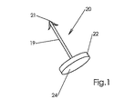
図1は、本発明の一実施形態によるファスナ20を示す。ファスナ20は好ましくは、ステンレススチールやニチノル(Nitinol(商標))等の生体適合性材料から作られる。ファスナ20は、有刺先端部21で途絶える枝19を有する。有刺先端部21は以下で述べるとおり、生体組織の中へ挿入されたファスナー20を生体組織内で定着させる役割を果たす。ファスナ20はまた、平らな円盤の形をした尾部分22を有し、同尾部分22より枝19が延在する。以下で説明するとおり、円盤22の表面24に力をかけファスナ20に運動エネルギーを与えることによって、ファスナ20は生体組織の中へ挿入され、その結果有刺先端部21が生体組織の中に入り、組織内に取り付けられる。表面24にかかる力は、例えば表面24にかかる圧縮流体または圧縮スプリングから生じてよい。
FIG. 1 illustrates a
図2は本発明のファスナの別の実施形態23を示すものであり、ここで枝19の先端部分28には2対以上のスプリング形状の刺25が設けてある。刺25は、先端部分28を生体組織の中へ挿入する最中に図2のaに示す圧縮構成を強いられる。先端部分28が生体組織の中へ挿入された後には、刺25が広がり図2のbに示す展開構成に入る。ファスナ23は好ましくは1対から10対の刺25を有し、より好ましくは2対から4対の刺25を有する。
FIG. 2 shows another
ファスナ23はまた円盤の形をした尾部分22を有し、図1の実施形態を参照しながら上で説明したとおり、生体組織の中へ先端部分28を挿入する最中には、同尾部分22へ力がかかる。円盤22には可撓性の尾部部材26が設けてある。尾部部材26は、生体組織の中へ遠位部分28を挿入する前には図2aに示す圧縮構成を強いられ、さらに円盤22が組織の中に入ることを防ぐため、広がって図2のbに示す展開構成に入る。可撓性部材26は可撓性シート27で覆うことができる。
The
図3は、本発明のこの態様の別の実施形態によるファスナ40を示す。ファスナ40は円盤状の末端42を有する。円盤42には、円盤42の縁49から延びる2つのスプリング形状の弓形フィン48が設けてある。フィン48は当初、固定装置の中にある時に縁49にもたれた状態を強いられ(図示せず)、固定装置から放出される時には末端42による生体組織の貫通を防ぐため、開いて図3の構成に入る。
FIG. 3 shows a
図4は、本発明の別の実施形態によるファスナ50を示す。ファスナ50は螺旋コイル51を備えている。螺旋コイル51の先端52には、生体組織を貫通し組織内で定着するための刺53が設けてある。螺旋コイルの末端54にはプロペラ52が設けてある。末端54に力をかけることによってファスナ50が生体組織に向かって進む時には、プロペラ54の作用によってファスナ50が回転し、生体組織の中へ先端をねじ込むことができる。螺旋コイル51は組織の中に入る時に縮むことがある。
FIG. 4 illustrates a
図5は、本発明の別の実施形態によるファスナ55を示す。ファスナ55はリング部分56を有し、同リング部分から2本の枝57が延在する。枝57は刺58のところで途絶える。ファスナ55は、ステンレススチール等、生体適合性の弾性またはスプリング形状の材料から形成される。ファスナ55は図5のaに示す休止または非強制構成をとり、同構成においてはリング部分56から外側に枝57が湾曲する。以下で説明するとおり、生体組織の中への挿入のためファスナ55は図5のbに示す構成を強いられ、同構成において枝57は真っ直ぐになる。枝57は生体組織の中に入る時に、図5のaに示す非強制構成に戻る。リング部分56は本来、図5のbに示すとおり円形の断面を有することがあり、さらに以下で述べるとおり、外科用細糸をつかむため図5のaに示す「I」字形の断面に変形することがある。あるいは代わりに、図5のbに示すとおり、リング部分56で2つの正反対に位置する突起60を切り欠いてもよい。突起は、固定装置の中に装填される時にリング部分56から出ない状態を強いられ、固定装置から放出される時には、外科用細糸をつかむため、図5のcに示すとおり自発的に内側へ突出する。
FIG. 5 illustrates a
図16は、本発明の別の実施形態によるファスナ200を示す。ファスナ200は、冠部202から延在する2本の有刺枝201を有する。ファスナ200には図16のaに示す非強制構成があり、同非強制構成では枝201が互いの方を向く。ファスナは固定装置の中へ装填される時に、図16のbに示す強制状態に入る。ファスナはその後固定装置から排出される時に、生体組織内で定着するため、図16のaに示す非強制構成を自発的にとる。図16のbに示す強制状態で、枝201は湾曲領域203にて冠部202に取り付けられているため、枝201と冠部202とは同一平面に位置しない。
FIG. 16 illustrates a
図21は、本発明の別の実施形態によるファスナ400を示す。ファスナ400は、有刺末端404のところで途絶える螺旋部分402を備える。螺旋部分402はD形固定具406から延在し、これに堅固に取り付けられている。よって固定具406の縁は、2つの円筒形の表面407と2つの平らな表面409とからなる。固定具406に搭載されたキャップ408は、十字形のソケット410を有する。ソケット410は、ファスナ402を回転させ、その結果ファスナ400を生体組織の中へねじ込むため、相補的十字形駆動ロッドを受け入れるよう構成されている。固定具406は2つの外側ねじ山412を有し、以下で説明するとおり、同外側ねじ山412は固定装置の内側ねじ山と係合する。
FIG. 21 illustrates a
図12は、本発明の一実施形態による外科用固定装置100を示す。固定装置100は、ファスナ55(図5)を生体組織の中へ挿入するために使用される。固定装置100は円筒形の銃身102を含み、以下で詳述するとおり、同銃身102中には複数のファスナ55が格納される。銃身102は遠位末端103と近位末端105とを有する。
FIG. 12 illustrates a
固定装置100は把持ハンドル101を有し、同把持ハンドル101から銃身102が延在する。把持ハンドル101は、以下で詳しく説明するとおり、銃身102内のファスナ55を生体組織の中へ排出する排出機構を取り囲む筐体104を有する。この排出機構は、利用者が筐体104のハンドル部分107に向けて引金106を絞ることによって作動される。筐体104はまた、生体組織をつなぎ合わせるために用いられる外科用細糸109のリール108を取り囲んでいる。このリール108から細糸109の末端分節が延び、銃身102の遠位末端にかけて筐体と銃身の中を通過する。細糸をリールに巻き戻すために利用者がリールを手動で回せるようにするため、リール108の一部は筐体104の外に延在している。ロックピン105aは、利用者がリール108をロックしてリール108の回転を阻止できるようにする。細糸109は図9のaに示すとおり、間断のない帯であってもよい。あるいは代わりに、細糸は図9のbに示すとおり、これの全長に沿って穴を有してもよい。細糸109はまた、図10に示すとおりメッシュであってもよい。
The fixing
図11は、固定装置100等の外科用固定装置を用いて、体腔の内側の2つの組織部位の各々にてファスナ55を挿入する外科処置を示す。図11のaに示すとおり、体表面の第1の位置116にて切開部を通じて被術者115の体腔119の中に装置100のシャフト102を導入する。体表面の第2の位置118では、第2の切開部を通じて体腔119の中に内視鏡117を導入する。内視鏡117は、ファスナ55を挿入すべき1つまたは複数の生体組織を含む体腔119を照らす。内視鏡は体腔119の画像をディスプレイ画面(図示せず)に表示する撮像システムの一部であるため、利用者120はファスナを挿入する時に体腔119を観察できる。体腔119内での固定装置100と内視鏡117との操作性を向上するため、体腔119は一時的に拡張されることがある。
FIG. 11 illustrates a surgical procedure in which a
図11のaでは、第1のファスナが挿入されることとなる体腔119の第1の位置122に、固定装置100の遠位末端103が置かれている。次に利用者はハンドル107に向けて引金106を絞ることによりファスナ排出機構を作動させ、シャフトの遠位末端から第1の位置122の組織の中へファスナを排出する。シャフトの遠位末端からファスナが排出されると、遠位末端103に近い細糸109沿いの位置にてファスナが細糸109の自由端を堅くつかみ、細糸の自由端は第1の位置122にて組織に固定される。
In FIG. 11a, the
図11のbは、細糸の自由端がファスナ121によって第1の位置122の生体組織に固定された後の細糸を示す。次に利用者がシャフトの遠位末端を第1の位置122から遠ざけると、把持ハンドルの中にあるリール108からシャフト102を通じて細糸109が給送される。第2の位置124に遠位末端103が接近する時には、リール108から余分な細片109が放出されることを防ぐため、筐体104(図12)上のロックピン105aを押し込むことによってリール108をロックすることもできる。遠位末端103が第2の位置124に向かってさらに動かされると、第1の位置121が第2の位置122に向かって引っ張られることにより、体器官123等の体器官の位置が第2の位置124に向かってずれる。第2の位置122でファスナを排出する前に、一定量の細糸をリールに戻して第1及び第2の位置間で細糸を緊張するため、利用者はリール108を手動で回すこともできる。
FIG. 11 b shows the thread after the free end of the thread is fixed to the living tissue at the
図11のcは、第2のファスナを生体組織の中に挿入することとなる体腔119内の第2の位置124に遠位末端103が置かれた後の、固定装置100を示す。図11のcから分かるように、この時、細糸は第1の位置122(ファスナ121により細片が生体組織に固定されているところ)から第2の位置124にかけて延在している。次に利用者は、第2の位置で第2のファスナを排出するため再びファスナ排出機構を作動させる。シャフトから第2のファスナが排出されると、これがシャフトの遠位末端近くで細糸をつかみ、第2の位置で細片を固定する。
FIG. 11c shows the
細糸109を切断するため、固定装置100はシャフトの遠位末端のところに、以下で述べるカッターを含む。図11のdは、ファスナ121及び125によりそれぞれ第1及び第2の位置122及び124にて末端のところで固定された細糸109の分節を解放するため、カッターによって切断された後の細片109を示す。このプロセスは1回の外科処置の中で必要に応じて繰り返されてよく、そうすることで体腔内で細糸片をいくらでも展開でき、器官123等の体器官を体腔内の所望の位置に固定できる。
To cut the
図13は、固定装置100のシャフト102の内部を示す。シャフト102は3つの同軸スリーブを備える。中間スリーブ115は、外側スリーブ110と内側スリーブ111との間に位置する。内側スリーブ111は環状の空隙によって中間スリーブ115から隔てられている。内側スリーブ110には、図5のbに示す強制構成をとる複数のファスナ55が搭載され、内側スリーブ110はファスナ55(図5)のリング部分56の中を通過し、それ故ファスナ55はそれぞれ内側及び中間スリーブ111及び115の間の環状空隙の中に位置する。内側スリーブには、以下で述べる排出機構によって内側スリーブ110が遠位方向に押される時にファスナ55を遠位方向に押す一連のラチェット突起112が設けてある。銃身内でファスナが縦方向に移動する時に銃身内でのファスナ55の回転を防ぐため、突起112の先端部を受け入れる切り欠き59を、ファスナ55のリング領域56(図5)に設けてもよい。以下で説明するとおり、ファスナが排出された後に銃身の近位末端105に向かって内側スリーブ110が縦方向に動く時に、銃身の近位末端105に向かうファスナ55の縦方向の動きを防ぐため、中間スリーブ115にはスプリング形状の突起116も設けてある。
FIG. 13 shows the inside of the
排出機構は、内側スリーブ110の近位末端に力をかけることにより、シャフト102の遠位末端103に向けて、スタック全体を1ラチェット単位だけ動かすよう構成されている。図13に示すとおり、こうしてスタック内の最遠位ファスナ55aがシャフトの遠位末端103から排出される。シャフト102の遠位末端103にはファスナ変形器113がある。シャフト102の遠位末端から最遠位ファスナ55が排出される時には、同ファスナがファスナ変形器113を通過し、そのリング部分56は図5bに示す円形から図5のaに示す「I」字形に変形する。円形部分56を「I」字形に変形させることにより、円形部分56は狭められ、細糸109の自由端を堅くつかむ。よって排出されるファスナは、図13に示すとおり、排出される時に細糸109の自由端を引く。排出されるファスナによって細糸109の末端が引かれる時には、スプール108が回転することによって、より多くの細糸が放出される。あるいは代わりに、突起59(図5)を用いて細糸109をつかんでもよい。
The ejection mechanism is configured to move the entire stack by one ratchet unit toward the
シャフト102からファスナ55が排出された後には、枝57が図5のaに示すこれの非強制構成に自発的に戻ることにより、生体組織上の特定の位置でファスナを堅く取り付けることができる(生体組織は図13に図示せず)。こうして細糸109の自由端もまた組織の同じ位置に堅く取り付けられる。
After the
図14は把持ハンドル107の内部を示す。内部スリーブ111はシャフト102から把持ハンドル107の中にまで延在し、リール108の近くで途絶える。細糸109はリール108から出て、シャフト102の遠位末端103にかけて内部スリーブ111の中を通る。引金106は、復元スプリング128によって図14に示す解除位置にスプリング付勢される。引金107を絞ると、上で説明したとおり、ファスナを排出するため内側スリーブ110の近位末端に力がかかる。リール108には、ロックピン105(図12)を受け入れるよう構成されたロックホール108aが設けてある。
FIG. 14 shows the inside of the
図15は、シャフト102の遠位末端103に位置する、細糸109を切断するためのカッターを示す。図15のaは、1対のファスナ131及び132によって、2つの位置にて生体組織(生体組織は図15に図示せず)に留められた後の、細糸109の分節を示す。このカッターは、シャフト102の遠位末端103から延在する外側スリーブ110の中に形成された「L」字形の切り欠き133からなる。外側スリーブ110を銃身の遠位末端に向けて縦方向にずらし、図15のbに示すとおり変形器113より先にこれを伸張させるには、レバー106a(図12及び図14)を銃身102まわりに回転させる。次に利用者は遠位末端103を操作しながら、図15bに示すとおり、細糸109を切り欠き133の中に入れる。次にレバー106aが解除される。復元スプリング107aの作用によりレバー106.5はこれの本来の位置に戻り、その結果外側スリーブ110は銃身の近位末端に向かって縦方向に移動する。こうして細糸109は、図15のcに示すとおり、切り欠き133の刃先134と変形器113との間でせん断される。
FIG. 15 shows a cutter for cutting the
図6、図7、及び図8は、本発明の別の実施形態に従って1つ以上のファスナを生体組織の中へ挿入する固定装置1を示す。固定装置1は、例えばファスナ20、28、40、または52の内いずれか1つを挿入するために使用されてよい。固定装置1は、複数のファスナ64を収容するマガジン63を受け入れるよう構成された挿入口62を含む。各々のファスナ64は金属製のシェル69に包まれている。シェル69の寸法はどれも同じであり、同寸法はマガジン63と銃身75の内のり寸法によって決まる。ただしシェル69は、サイズと形状が異なるファスナを収容できる。このようにマガジン63には、用途に応じて適宜に形状の異なるファスナを装填できる。
6, 7 and 8 show a fixation device 1 for inserting one or more fasteners into living tissue according to another embodiment of the present invention. The fixation device 1 may be used for inserting any one of the
マガジン63は、好ましくは5から40のシェル69を保持でき、より好ましくは10から20のシェル69を保持でき、各々のシェルはファスナ65を収容する。シェル69は、マガジン63内の金属性スプリングによって銃身75に向けて一度に1つずつ給送される。ファスナ65を排出した後、排出されたファスナのシェルは銃身75の外に排出されるが、これを袋または缶で別途回収してもよい。
The magazine 63 can preferably hold 5 to 40
固定装置1はまた、ファスナに運動エネルギーを与えることで銃身75を通じて固定装置からファスナを排出する、排出機構を含む。この排出機構は機械式(つまりスプリング式)であってもよい。あるいは代わりに、図8に示すとおり、排出機構は気圧式または水圧式機構であってもよい。引金78を押し込むと空気弁77が解放し、その結果圧縮空気等の圧縮ガスが、あるいは加圧液体流体が、供給源(図示せず)から固定装置1の銃身75の中へ送り込まれ、これが銃身75内のファスナ65に運動エネルギーを与える。こうしてファスナ65は固定装置1から排出される。
The fixation device 1 also includes a discharge mechanism that discharges the fastener from the fixation device through the
銃身75において機械的給送機構やファスナ変形機構が存在しないため、固定装置1の銃身75は従来の固定器具の銃身直径より小さい直径のものにできる。例えば、ファスナの最大外径が1mmならば、銃身75の外径を2mm程度と小さくできる。
Since there is no mechanical feeding mechanism or fastener deformation mechanism in the
固定装置1はまた、外科用細糸10のリールを収容するカートリッジ13を含む。銃身75に細糸10を取り付ける場合には、外側の直径が最大10mmの、好ましくは最大5mmのカバーチューブ(図示せず)で、銃身75と細糸10の両方を収容できる。固定装置1を使用する前には、図7に示すとおり、末端11が銃身5の遠位末端6を覆うまで銃身75に沿って細糸が引き出される。細糸10には一連の穴が設けてある。ファスナが銃身を通過すると細糸がファスナ20の軌道を通過し、その結果ファスナの先端部は細糸の穴12を通過する。ファスナの尾部22は穴を通過できないため、ファスナが組織を貫通すると細糸の末端が組織に固定される。その後、リールから一定量の細糸を放出して第2のファスナを排出してもよい。こうして生体組織の2箇所で細糸が固定される。
The fixation device 1 also includes a
次に切断機構40により細糸を切断する。固定装置1は、生体組織の2箇所に細糸を固定した後に細糸10を切断する切断機構40を含む。図7に示すとおり、切断機構には、機械式のはさみ、熱線システム、あるいはプレート42によって銃身5から隔離されたホットRFチップエレメント41を、用いることができる。切断エレメントのための電気エネルギーは、電源装置等の外部供給源から、またはRF発生器から取ることができ、あるいは内蔵装置バッテリーとすることができる。切断の後、分離された細糸片によって2つの組織位置が接続されることにより、組織の支えを提供する、あるいは2つの組織をまとめて保持する。
Next, the fine thread is cut by the
図17は、本発明の別の実施形態による外科用固定装置300を示す。固定装置300は、ファスナ200(図16)を生体組織の中へ挿入するために使用される。固定装置300は、把持ハンドル302と銃身304とを有する。銃身304は、遠位末端308と近位末端309とを有する。把持ハンドル302は、銃身304の遠位末端308からファスナを排出するための排出機構を収容する筐体306を有する。以下で説明するとおり、排出機構は、把持ハンドルのハンドル部分312に向けて引金310を絞ることによって作動させる。遠位末端308から排出されたファスナによって、細糸314が生体組織に固定される。
FIG. 17 illustrates a
図18は細糸314を示す。細糸314は当初、閉じた輪である。細糸314は、これの全長に沿って2列の穿孔316を有する。固定装置300に細糸314を装填すると、細糸314は、銃身304の近位末端309と遠位末端308とのまわりで輪をなす。
FIG. 18 shows the
図19のaから図19のgは、数通りの視点から銃身304の遠位末端308をより詳しく示す。銃身304はファスナ200のスタックを収容する。銃身304の中のファスナ200は図16のbに示す強制状態にある。
Figures 19a to 19g show in more detail the
銃身304の遠位末端308には、第1のローラー318と1対のローラーカッター320とがある。シャフト304の中で細糸314が動くと、ローラーカッター320が細糸314を穿孔316に沿って切断する。こうして、各縁に沿って一連の切り欠き304を有する細糸314の一部分322が、遠位末端308から放出される。残りの繊維326はシャフトの近位末端304まで続く。
At the
中央ロッド330は銃身304の全長に沿って延在する。ロッド330の遠位末端には軸334のところで舌部332がヒンジ式に取り付けられている。舌部332の遠位縁336は、最遠位ファスナ200aの冠部202(図16)に接する。ロッド330の遠位末端から平らなスプリング340が延在しており、これが舌部332の遠位縁336を冠部202に接した状態に保つ。銃身304の遠位末端には、細糸314を切断するためのカッター305が設けてある。このカッターは、例えばブレード、高周波(RF)カッター、または熱線カッターであってよい。
The
引金310を絞ると(図17)、銃身304の遠位末端308に向けてロッド330が移動する。次にこのロッド330の動きによって、最遠位ファスナ200aが遠位末端308から排出される。最遠位ファスナが遠位末端から排出されると、枝201が細糸314の縁沿いの切り欠き304を通過し、次にこれの非強制構成(図16のa)に戻ることにより生体組織に固定される。(生体組織は図19に図示せず)。
When the
その後引金310を解除すると、銃身304の近位末端309に向けてロッド330が縦方向に移動する。次に、銃身304の中では、ファスナ200のスタックが遠位末端308に向かって移動する。ファスナ200bが舌部332の傍らを滑進する時には、舌部が平らなスプリング340にもたれて軸334まわりに僅かに回転する。ファスナ200bの冠部200が舌部332の遠位縁336を通過すると、遠位縁336がスプリング340の作用で軸334まわりに回転するから、遠位縁336はファスナ200bの冠部200の真上に位置し、且つこれに接する。次に引金310を絞ると、上で説明したとおり遠位末端208からファスナ200bが排出される。
When the
図20のa及び図20のbは、分かりやすくするため筐体306が取り除かれた状態で、固定装置300の把持ハンドル302を示す。中央ロッド330は把持ハンドル302の中、これの近位末端にて延在する。ロッド330に取り付けられた環状の棚342は、ロッド330の拡大部分348を包囲する螺旋スプリング346を支える。ハンドル部分312に向けて引金310を絞ると、ロッド330を包囲し且つ螺旋スプリング346上に搭載された環状リング350が、引金310の第1の拡張部354によって押し下げられる。棚342の下のストップ352は、引金を絞る時にロッドが遠位方向に縦方向でずれるのを防ぐ。これにより螺旋スプリング346は圧縮される。引金310を絞り続けると、引金310の第2の拡張部356がストップ352に接し、その結果ストップ352は棚342の下から外に軸358まわりに回転することにより、圧縮されたスプリング348はこれの休止状態に速やかに戻ることができ、遠位でロッド330を駆動し、上で述べたとおりファスナを排出する。
20a and 20b show the grip handle 302 of the
把持ハンドル302はまた、細糸314で所望の張力を維持するためのノブ360(図17、図20のa、及び図20のb)を含む。ノブ362は細糸314をロックするために使用される。
The grip handle 302 also includes a knob 360 (FIGS. 17, 20a, and 20b) for maintaining the desired tension with the
図22は、本発明の別の実施形態による固定装置420を示す。固定装置420は、ファスナ400を生体組織の中へ挿入するために使用されてよい。固定装置420は把持ハンドル422を有しており、同把持ハンドル422から銃身424が延在する。銃身424は、遠位末端428と、把持ハンドルの内側に位置する近位末端430とを有する。把持ハンドル422は、銃身424の遠位末端428からファスナ400を排出するための排出機構を取り囲む、筐体426を有する。この排出機構は、把持ハンドル422のハンドル部分434に向けて引金432を絞ることによって作動される。以下で説明するとおり、遠位末端428から排出されたファスナ400は、細片436を生体組織に固定する。
FIG. 22 shows a
図23にてより詳細に示された中央ロッド440は、把持ハンドル422から銃身の中にまで延在し、銃身424の中、遠位末端428に向かって最上位のファスナ400aの近くで途絶える。ロッド440は、遠位部分442と近位部分444とを有する。遠位部分442は十字形の断面を有し、ファスナ400(図21)の十字形ソケット410で受け入れられるよう構成されている。遠位部分は銃身424の内側に位置する。近位部分444は把持ハンドル422の中に位置し、円形の断面を有する。近位部分444には螺旋状のねじ山446が設けてある。近位部分にはまた、ピッチが螺旋ねじ山446のピッチよりも大きい、螺旋状の溝448が設けてある。穴454はロッド440を通じて延在する。
The
把持ハンドル422はセレクタ448を含む。セレクタ448は、筐体426の外に延在する一体型レバー450を有する。セレクタ448は、レバー450が上昇する図22に示す第1の位置と、レバー450が下降する第2の位置(図示せず)とで交代できる。レバー450は、ロッド440を包囲する螺旋スプリング452によって下降位置にスプリング付勢される。
The grip handle 422 includes a
セレクタ448は、ロッド440を包囲するコントロールキャビティ456を有する。スプリング452に当ててレバー450を上昇させると、セレクタが図22に示す構成に入り、同構成においては中央キャビティ445の部分沿いの内側ねじ山454が、ロッド440(図23)の近位部分444沿いの外側螺旋ねじ山446と係合する。レバー450がこれの上昇位置で保持された状態で引金432を絞ると、ロッド440が遠位末端428に向かって縦方向に移動する。そして銃身424の中の最近位ファスナ400aのソケット410が、ロッドの遠位末端を受け入れる。次にレバー450が解除されると、スプリング452の作用でこれの下降位置に復帰する。この構成において、セレクタ448はこれの第2の構成にあり、同第2の構成では、第2の内側ねじ山458がロッド440の近位部分沿いの螺旋溝448に係合する。次に引金432を解除するとロッド440が回転する。ロッド440の遠位末端は、銃身内の最上位ファスナ400aのソケット410に挿入されているから、ロッド410の回転は最上位ファスナ400aの回転を駆動する。
The
図24に示すとおり、銃身424の内側には内側スリーブ460がある。この内側スリーブはファスナ400のスタックを包囲する。内側スリーブ460は円筒形の部分462を有する。細糸426を切断するため、円筒形部分462の下からは2つの正反対に位置する切断ブレード464が延在する。円筒形部分462より上には2つの正反対に位置する突起466が延在する。突起466は平面であり、互いに平行し、銃身424の全長に沿って延在する。ファスナ400の平らな表面409が内側スリーブ460の平らなプロジェクタ466に平行となるよう、プロジェクタ466の間でファスナ400のスタックが配向される。よって上で説明したとおり、ロッド440によるスタック内の最上位ファスナ400aの回転は内側スリーブ460の回転を引き起こし、次にこれがスタック内の全ファスナ400の回転を引き起こす。スタック内の最下位ファスナ400bの回転によって、最下位ファスナ400bの螺旋部分402が生体組織の中へねじ込まれる。
As shown in FIG. 24, inside the
図25は、銃身の遠位末端428をより詳しく示す。銃身の遠位末端428から最下位ファスナ400bが意図せず落ちるのを防ぐため、銃身424の内側表面上の内側ねじ山470は、最下位ファスナ400(図21)の固定具407上の外側ねじ山412と係合する。よって、上で説明したとおり、最下位ファスナ400bはロッド440によって回転される時に限り遠位末端から排出できる。
FIG. 25 shows the
細糸426はファスナ400のスタックを通過し、遠位末端428より先まで延在する。細糸は円形の断面を有し、さらにその全長に沿って周期的に配置された隆起468を有する。例えば、細糸426の長さに沿って1センチメートル毎に隆起468を配置してもよい。
The
細糸426の直径は、最下位ファスナ400bの螺旋部分402の巻きの間隔に満たない。ただし隆起468はあまりに広いため、最下位ファスナ400bの螺旋部分402の巻きの間を通過できない。よって銃身の遠位末端428から最下位ファスナ400bが排出され、生体組織の中にねじ込まれる時には、細糸は螺旋部分402の巻きの間に入り、かくして生体組織に留められる。隆起468の存在は、細糸がファスナ400bの下に落ちることを防ぐ。その際レバー450と引金432が上昇すると、内側スリーブ460が遠位末端428より先まで伸張する。そして図24に示すとおり、切断ブレード464によって細糸が切断される。
The diameter of the
図26は、緊張性尿失禁の膣式修復の一方法における本発明の固定装置の使用を示す。図26のaでは腹部の図で、そして図26のbでは膣の図で、処置が示してある。尿道の上、前膣壁に5mmから10mmの切開部を作る。次に膣壁と尿道骨盤靭帯との間、同靭帯の結合部に向けて骨盤内筋膜の弓状靭帯にかけて、左右相称に平面を作る。切開部を通じて骨盤内筋膜に向けて本発明の固定装置を導入する。次に固定装置から本発明のファスナ502を排出することにより、片側の骨盤内筋膜の第1の位置500にて細糸504の末端を留める。次に膣切開部を通じてファスナを取り除き、膣切開部を通じて反対側の骨盤内筋膜まで再び導入し、固定装置から第2のファスナ506を排出することにより、骨盤内筋膜の第2の側の第2の位置508で細糸を留める。次にファスナによって細糸504を切断することにより、2つの骨盤内筋膜の間に差し渡された細糸片を残す。次に膣切開部を通じてファスナを取り除く。
FIG. 26 illustrates the use of the fixation device of the present invention in a method of vaginal repair of stress urinary incontinence. The treatment is shown in the abdominal view in FIG. 26a and in the vagina in FIG. 26b. A 5-10 mm incision is made in the anterior vaginal wall above the urethra. Next, between the vaginal wall and the urethral pelvic ligament, the arcuate ligament of the pelvic fascia toward the joint part of the ligament, a plane is made in a bilaterally symmetrical manner. The fixation device of the present invention is introduced toward the pelvic fascia through the incision. Next, the
Claims (38)
(f)把持ハンドルと、
(g)前記把持ハンドルから延在する細長いシャフトと、
(h)1つ以上の外科用ファスナを収容するよう構成された隔室と、
(i)前記隔室から外科用ファスナを排出する作動可能排出機構と、
(j)前記シャフトに沿って外科用細糸を分配することにより、ファスナが前記シャフトから排出される時に前記細糸をつかむよう構成された、細糸分配システムと、
を備える、外科用固定装置。 A surgical fixation device for fixing a surgical thread to a living tissue,
(F) a grip handle;
(G) an elongate shaft extending from the grip handle;
(H) a compartment configured to receive one or more surgical fasteners;
(I) an operable discharge mechanism for discharging surgical fasteners from the compartment;
(J) a thread dispensing system configured to grasp the thread as the fastener is ejected from the shaft by dispensing surgical thread along the shaft;
A surgical fixation device comprising:
Applications Claiming Priority (2)
| Application Number | Priority Date | Filing Date | Title |
|---|---|---|---|
| US48626403P | 2003-07-11 | 2003-07-11 | |
| PCT/IL2004/000624 WO2005004727A1 (en) | 2003-07-11 | 2004-07-11 | Surgical fasteners and devices for surgical fastening |
Publications (1)
| Publication Number | Publication Date |
|---|---|
| JP2007518446A true JP2007518446A (en) | 2007-07-12 |
Family
ID=34062119
Family Applications (1)
| Application Number | Title | Priority Date | Filing Date |
|---|---|---|---|
| JP2006520100A Pending JP2007518446A (en) | 2003-07-11 | 2004-07-11 | Surgical fasteners and surgical fixation devices |
Country Status (6)
| Country | Link |
|---|---|
| US (1) | US20070088390A1 (en) |
| EP (1) | EP1646319A1 (en) |
| JP (1) | JP2007518446A (en) |
| AU (1) | AU2004255056A1 (en) |
| CA (1) | CA2532882A1 (en) |
| WO (1) | WO2005004727A1 (en) |
Cited By (5)
| Publication number | Priority date | Publication date | Assignee | Title |
|---|---|---|---|---|
| JP2011500220A (en) * | 2007-10-19 | 2011-01-06 | コーディス・コーポレイション | Push-in retainer system for use in direct annuloplasty procedures for mitral regurgitation |
| JP2012532733A (en) * | 2009-07-13 | 2012-12-20 | シー・アール・バード・インコーポレーテッド | Surgical fastener applicator |
| JP2013517107A (en) * | 2010-01-20 | 2013-05-16 | ニュー ホープ ベンチャーズ,リミティド パートナーシップ | Tissue repair implant, delivery device and delivery method |
| JP2015524706A (en) * | 2012-08-07 | 2015-08-27 | ジフト エルエルシーZift Llc | Tissue attachment device and method |
| JP2016540615A (en) * | 2013-11-18 | 2016-12-28 | エシコン・インコーポレイテッドEthicon, Inc. | Implantable surgical fastening device |
Families Citing this family (125)
| Publication number | Priority date | Publication date | Assignee | Title |
|---|---|---|---|---|
| US7160312B2 (en) | 1999-06-25 | 2007-01-09 | Usgi Medical, Inc. | Implantable artificial partition and methods of use |
| US7618426B2 (en) | 2002-12-11 | 2009-11-17 | Usgi Medical, Inc. | Apparatus and methods for forming gastrointestinal tissue approximations |
| US8574243B2 (en) | 1999-06-25 | 2013-11-05 | Usgi Medical, Inc. | Apparatus and methods for forming and securing gastrointestinal tissue folds |
| US7416554B2 (en) | 2002-12-11 | 2008-08-26 | Usgi Medical Inc | Apparatus and methods for forming and securing gastrointestinal tissue folds |
| EP2263554B1 (en) | 2002-06-11 | 2013-05-29 | Covidien LP | Tool for hernia mesh tacks |
| US7942898B2 (en) | 2002-12-11 | 2011-05-17 | Usgi Medical, Inc. | Delivery systems and methods for gastric reduction |
| US7942884B2 (en) | 2002-12-11 | 2011-05-17 | Usgi Medical, Inc. | Methods for reduction of a gastric lumen |
| US8926637B2 (en) | 2003-06-13 | 2015-01-06 | Covidien Lp | Multiple member interconnect for surgical instrument and absorbable screw fastener |
| EP1635723B1 (en) | 2003-06-13 | 2011-08-10 | Tyco Healthcare Group LP | Multiple member interconnect for surgical instrument and absorbable screw fastener |
| US8308765B2 (en) | 2004-05-07 | 2012-11-13 | Usgi Medical, Inc. | Apparatus and methods for positioning and securing anchors |
| US8216252B2 (en) | 2004-05-07 | 2012-07-10 | Usgi Medical, Inc. | Tissue manipulation and securement system |
| US7736372B2 (en) | 2003-11-13 | 2010-06-15 | Usgi Medical, Inc. | Apparatus and methods for endoscopic suturing |
| US7347863B2 (en) | 2004-05-07 | 2008-03-25 | Usgi Medical, Inc. | Apparatus and methods for manipulating and securing tissue |
| US20050251189A1 (en) | 2004-05-07 | 2005-11-10 | Usgi Medical Inc. | Multi-position tissue manipulation assembly |
| US7361180B2 (en) | 2004-05-07 | 2008-04-22 | Usgi Medical, Inc. | Apparatus for manipulating and securing tissue |
| US10478179B2 (en) | 2004-04-27 | 2019-11-19 | Covidien Lp | Absorbable fastener for hernia mesh fixation |
| US7390329B2 (en) | 2004-05-07 | 2008-06-24 | Usgi Medical, Inc. | Methods for grasping and cinching tissue anchors |
| US8257394B2 (en) | 2004-05-07 | 2012-09-04 | Usgi Medical, Inc. | Apparatus and methods for positioning and securing anchors |
| US7736374B2 (en) | 2004-05-07 | 2010-06-15 | Usgi Medical, Inc. | Tissue manipulation and securement system |
| US7520884B2 (en) | 2004-05-07 | 2009-04-21 | Usgi Medical Inc. | Methods for performing gastroplasty |
| US7695493B2 (en) | 2004-06-09 | 2010-04-13 | Usgi Medical, Inc. | System for optimizing anchoring force |
| AU2006212876A1 (en) * | 2005-02-07 | 2006-08-17 | Regen Biologics, Inc. | System and method for all-inside suture fixation for implant attachment and soft tissue repair |
| US8128640B2 (en) * | 2005-02-07 | 2012-03-06 | Ivy Sports Medicine LLC | System and method for all-inside suture fixation for implant attachment and soft tissue repair |
| AU2006231632B2 (en) | 2005-04-05 | 2012-01-19 | Boston Scientific Scimed, Inc. | Articles, devices, and methods for pelvic surgery |
| WO2007002012A1 (en) | 2005-06-21 | 2007-01-04 | Ams Research Corporation | Apparatus for securing a urethral sling to pubic bone |
| WO2007002071A1 (en) | 2005-06-21 | 2007-01-04 | Ams Research Corporation | Apparatus for securing a urethral sling to pubic bone |
| JP5145219B2 (en) * | 2005-07-06 | 2013-02-13 | アイ.ビー.アイ イスラエル バイオメディカル イノベーションズ リミテッド | Surgical fasteners and fastening devices |
| US8535217B2 (en) | 2005-07-26 | 2013-09-17 | Ams Research Corporation | Methods and systems for treatment of prolapse |
| WO2007017872A2 (en) * | 2005-08-11 | 2007-02-15 | Endogun Medical Systems Ltd. | Surgical fasteners and devices for surgical fastening |
| EP1948073B1 (en) | 2005-11-14 | 2014-03-19 | C.R.Bard, Inc. | Sling anchor system |
| AU2007253683B2 (en) | 2006-05-19 | 2012-12-06 | Boston Scientific Scimed, Inc. | Method and articles for treatment of stress urinary incontinence |
| US8834350B2 (en) | 2006-06-16 | 2014-09-16 | Ams Research Corporation | Surgical implants, tools, and methods for treating pelvic conditions |
| EP2049039A2 (en) | 2006-06-22 | 2009-04-22 | AMS Research Corporation | Adjustable tension incontinence sling assemblies |
| US8870916B2 (en) | 2006-07-07 | 2014-10-28 | USGI Medical, Inc | Low profile tissue anchors, tissue anchor systems, and methods for their delivery and use |
| WO2008033950A2 (en) | 2006-09-13 | 2008-03-20 | C. R. Bard, Inc. | Urethral support system |
| ES2664870T3 (en) * | 2006-10-10 | 2018-04-23 | Adrian Edward Park | Adjustable line and network retractors |
| EP2063790B1 (en) | 2006-10-26 | 2016-01-27 | AMS Research Corporation | Surgical articles for treating pelvic conditions |
| US8951185B2 (en) | 2007-10-26 | 2015-02-10 | Ams Research Corporation | Surgical articles and methods for treating pelvic conditions |
| FR2919487B1 (en) * | 2007-07-31 | 2010-10-29 | Sofradim Production | SURGICAL BAND REEL |
| US8206280B2 (en) | 2007-11-13 | 2012-06-26 | C. R. Bard, Inc. | Adjustable tissue support member |
| US9044235B2 (en) | 2008-02-18 | 2015-06-02 | Covidien Lp | Magnetic clip for implant deployment device |
| US9393093B2 (en) | 2008-02-18 | 2016-07-19 | Covidien Lp | Clip for implant deployment device |
| US9833240B2 (en) | 2008-02-18 | 2017-12-05 | Covidien Lp | Lock bar spring and clip for implant deployment device |
| US8758373B2 (en) | 2008-02-18 | 2014-06-24 | Covidien Lp | Means and method for reversibly connecting a patch to a patch deployment device |
| US9301826B2 (en) | 2008-02-18 | 2016-04-05 | Covidien Lp | Lock bar spring and clip for implant deployment device |
| CA2715740C (en) | 2008-02-18 | 2014-05-27 | Polytouch Medical Ltd. | A device and method for deploying and attaching a patch to a biological tissue |
| US9398944B2 (en) | 2008-02-18 | 2016-07-26 | Covidien Lp | Lock bar spring and clip for implant deployment device |
| US9034002B2 (en) | 2008-02-18 | 2015-05-19 | Covidien Lp | Lock bar spring and clip for implant deployment device |
| US8317808B2 (en) | 2008-02-18 | 2012-11-27 | Covidien Lp | Device and method for rolling and inserting a prosthetic patch into a body cavity |
| US8808314B2 (en) | 2008-02-18 | 2014-08-19 | Covidien Lp | Device and method for deploying and attaching an implant to a biological tissue |
| US9393002B2 (en) | 2008-02-18 | 2016-07-19 | Covidien Lp | Clip for implant deployment device |
| EP2792307B1 (en) | 2008-10-20 | 2017-10-04 | Covidien LP | A device for attaching a patch to a biological tissue |
| EP2349018B1 (en) | 2008-10-27 | 2018-08-01 | Boston Scientific Scimed, Inc. | Surgical needle and anchor system with retractable features |
| AU2010214097B2 (en) | 2009-02-10 | 2015-12-03 | Ams Research Corporation | Surgical articles for treating urinary incontinence |
| US8728099B2 (en) * | 2009-05-12 | 2014-05-20 | Ethicon, Inc. | Surgical fasteners, applicator instruments, and methods for deploying surgical fasteners |
| US8579920B2 (en) | 2009-05-12 | 2013-11-12 | Ethicon, Inc. | Surgical fasteners, applicator instruments, and methods for deploying surgical fasteners |
| US8894669B2 (en) | 2009-05-12 | 2014-11-25 | Ethicon, Inc. | Surgical fasteners, applicator instruments, and methods for deploying surgical fasteners |
| US8728098B2 (en) * | 2009-05-12 | 2014-05-20 | Ethicon, Inc. | Surgical fasteners, applicator instruments, and methods for deploying surgical fasteners |
| USD698021S1 (en) | 2009-05-12 | 2014-01-21 | Ethicon, Inc. | Surgical fastener |
| US9055945B2 (en) | 2009-05-12 | 2015-06-16 | Ethicon, Inc. | Surgical fasteners having articulating joints and deflectable tips |
| USD744646S1 (en) | 2009-05-12 | 2015-12-01 | Ethicon, Inc. | Surgical fastener |
| US8920439B2 (en) | 2009-05-12 | 2014-12-30 | Ethicon, Inc. | Applicator instruments having curved and articulating shafts for deploying surgical fasteners and methods therefor |
| US9192377B1 (en) * | 2009-06-02 | 2015-11-24 | Cardica, Inc. | Work hardening of staples within surgical stapler |
| CA2769666C (en) | 2009-08-17 | 2018-02-13 | Arie Levy | Means and method for reversibly connecting an implant to a deployment device |
| EP2467093B1 (en) | 2009-08-17 | 2019-08-28 | Covidien LP | Articulating patch deployment device |
| WO2011041571A2 (en) * | 2009-10-01 | 2011-04-07 | Kardium Inc. | Medical device, kit and method for constricting tissue or a bodily orifice, for example, a mitral valve |
| CA2785830A1 (en) | 2009-12-30 | 2011-07-07 | Ams Research Corporation | Implantable sling systems and methods |
| US9393091B2 (en) | 2009-12-31 | 2016-07-19 | Astora Women's Health, Llc | Suture-less tissue fixation for implantable device |
| US9980708B2 (en) | 2010-01-20 | 2018-05-29 | Micro Interventional Devices, Inc. | Tissue closure device and method |
| US10743854B2 (en) | 2010-01-20 | 2020-08-18 | Micro Interventional Devices, Inc. | Tissue closure device and method |
| US10959840B2 (en) | 2010-01-20 | 2021-03-30 | Micro Interventional Devices, Inc. | Systems and methods for affixing a prosthesis to tissue |
| US10058314B2 (en) | 2010-01-20 | 2018-08-28 | Micro Interventional Devices, Inc. | Tissue closure device and method |
| EP4218668B1 (en) | 2010-02-23 | 2025-08-20 | Boston Scientific Scimed, Inc. | Surgical articles for treating incontinence |
| US9445881B2 (en) | 2010-02-23 | 2016-09-20 | Boston Scientific Scimed, Inc. | Surgical articles and methods |
| US8951268B2 (en) | 2010-05-17 | 2015-02-10 | I.B.I. Israel Biomedical Innovations Ltd. | Surgical fastening device with mesh retaining means |
| US8622440B2 (en) * | 2010-10-05 | 2014-01-07 | Ideal Industries, Inc. | Knot tying device and cartridge system for providing tying filament thereto |
| US9125717B2 (en) | 2011-02-23 | 2015-09-08 | Ams Research Corporation | Implant tension adjustment system and method |
| US20130006049A1 (en) | 2011-06-30 | 2013-01-03 | Alexander James A | Implants, tools, and methods for treatments of pelvic conditions |
| USD721175S1 (en) | 2011-09-08 | 2015-01-13 | Ams Research Corporation | Backers for surgical indicators |
| USD736382S1 (en) | 2011-09-08 | 2015-08-11 | Ams Research Corporation | Surgical indicator with backers |
| USD721807S1 (en) | 2011-09-08 | 2015-01-27 | Ams Research Corporation | Surgical indicators |
| US9474526B2 (en) | 2011-09-09 | 2016-10-25 | Boston Scientific Scimed, Inc. | Tissue anchor with insertion device |
| WO2013134313A1 (en) * | 2012-03-06 | 2013-09-12 | Phillip A. Williams, Md, Pc | Medical device, method and system thereof |
| US9351733B2 (en) | 2013-01-18 | 2016-05-31 | Covidien Lp | Surgical fastener applier |
| US9358010B2 (en) | 2013-03-12 | 2016-06-07 | Covidien Lp | Flex cable and spring-loaded tube for tacking device |
| US9427230B2 (en) | 2013-03-14 | 2016-08-30 | C.R. Bard, Inc. | Handling of fasteners within a surgical instrument |
| US9867620B2 (en) | 2013-03-14 | 2018-01-16 | Covidien Lp | Articulation joint for apparatus for endoscopic procedures |
| US9474530B2 (en) | 2013-03-14 | 2016-10-25 | C.R. Bard, Inc. | Handling of fasteners within a surgical instrument |
| US9655621B2 (en) | 2013-03-15 | 2017-05-23 | Covidien Lp | Surgical instrument for dispensing tacks and solution |
| EP3003166A4 (en) * | 2013-06-05 | 2017-06-14 | LC Therapeutics, Inc. | Tissue anchor and deployment device for same |
| US10085746B2 (en) | 2013-06-28 | 2018-10-02 | Covidien Lp | Surgical instrument including rotating end effector and rotation-limiting structure |
| US9668730B2 (en) | 2013-06-28 | 2017-06-06 | Covidien Lp | Articulating apparatus for endoscopic procedures with timing system |
| US9358004B2 (en) | 2013-06-28 | 2016-06-07 | Covidien Lp | Articulating apparatus for endoscopic procedures |
| US9351728B2 (en) | 2013-06-28 | 2016-05-31 | Covidien Lp | Articulating apparatus for endoscopic procedures |
| US20150032130A1 (en) | 2013-07-24 | 2015-01-29 | Covidien Lp | Expanding absorbable tack |
| US20160058442A1 (en) * | 2013-07-24 | 2016-03-03 | Covidien Lp | Expanding hernia fixation tack |
| US9526498B2 (en) | 2013-09-17 | 2016-12-27 | Covidien Lp | Surgical device with a trigger lockout mechanism device |
| US9615830B2 (en) | 2013-11-08 | 2017-04-11 | C.R. Bard, Inc. | Surgical fastener |
| US9675353B2 (en) | 2013-11-08 | 2017-06-13 | C.R. Bard, Inc. | Surgical fasteners and associated deployment devices |
| US10368870B2 (en) * | 2013-11-08 | 2019-08-06 | C.R. Bard, Inc. | Surgical fastener |
| US9445814B2 (en) | 2013-11-08 | 2016-09-20 | C.R. Bard, Inc. | Surgical fastener |
| EP3110339A1 (en) | 2014-02-28 | 2017-01-04 | Saturix Ltd. | Devices and methods for closing openings in body tissue |
| DE102014004772A1 (en) * | 2014-04-01 | 2015-10-01 | Ruprecht-Karls-Universität Heidelberg | Surgical device, method of using the surgical device and suture |
| US10335146B2 (en) | 2014-04-02 | 2019-07-02 | Coviden Lp | Surgical fastener applying apparatus, kits and methods for endoscopic procedures |
| US11246583B2 (en) * | 2014-06-18 | 2022-02-15 | Boston Scientific Scimed, Inc. | Insertion devices, anchors, and methods for securing an implant |
| US20160089130A1 (en) * | 2014-09-30 | 2016-03-31 | Biomet Sports Medicine, Llc | Soft Tissue Attachment |
| US11090097B2 (en) | 2015-03-17 | 2021-08-17 | Covidien Lp | Connecting end effectors to surgical devices |
| US10932769B2 (en) | 2016-05-26 | 2021-03-02 | Ivy Sports Medicine, Llc | System and method for all-inside suture fixation for implant attachment and soft tissue repair |
| US11298123B2 (en) | 2016-10-21 | 2022-04-12 | Covidien Lp | Surgical end effectors |
| US10617409B2 (en) | 2016-10-21 | 2020-04-14 | Covidien Lp | Surgical end effectors |
| US10743859B2 (en) | 2016-10-21 | 2020-08-18 | Covidien Lp | Surgical end effectors |
| CN114099057A (en) * | 2016-11-29 | 2022-03-01 | 埃斯卡拉医疗公司 | Anchor delivery systems and methods |
| US10687804B2 (en) * | 2016-12-07 | 2020-06-23 | Ethicon, Inc. | Applicator instruments having surgical fastener insertion tools for dispensing surgical fasteners |
| US10888309B2 (en) | 2017-01-31 | 2021-01-12 | Covidien Lp | Surgical fastener devices with geometric tubes |
| WO2019133516A1 (en) * | 2017-12-29 | 2019-07-04 | Laprozip, Llc | Absorbable clip/staple and applicator for deployment |
| DE102018100478A1 (en) * | 2018-01-10 | 2019-07-11 | Böllhoff Verbindungstechnik GmbH | Screw for a screw connection with a component |
| US11298126B2 (en) | 2018-05-02 | 2022-04-12 | Covidien Lp | Shipping wedge for end effector installation onto surgical devices |
| US11116500B2 (en) | 2018-06-28 | 2021-09-14 | Covidien Lp | Surgical fastener applying device, kits and methods for endoscopic procedures |
| US20200268371A1 (en) * | 2019-02-27 | 2020-08-27 | Covidien Lp | Purse string suture device |
| EP3943015A4 (en) * | 2019-03-22 | 2022-12-07 | Tohoku University | Anchor instrument |
| US11523817B2 (en) | 2019-06-27 | 2022-12-13 | Covidien Lp | Endoluminal pursestring device |
| USD944984S1 (en) | 2019-12-19 | 2022-03-01 | Covidien Lp | Tubular positioning guide |
| USD944985S1 (en) | 2019-12-19 | 2022-03-01 | Covidien Lp | Positioning guide cuff |
| US11197675B2 (en) | 2019-12-19 | 2021-12-14 | Covidien Lp | Positioning guide for surgical instruments and surgical instrument systems |
| US20240268811A1 (en) * | 2023-02-09 | 2024-08-15 | Biomet Manufacturing, Llc | Handheld self-punching device |
Family Cites Families (6)
| Publication number | Priority date | Publication date | Assignee | Title |
|---|---|---|---|---|
| US5725529A (en) * | 1990-09-25 | 1998-03-10 | Innovasive Devices, Inc. | Bone fastener |
| US5470010A (en) * | 1991-04-04 | 1995-11-28 | Ethicon, Inc. | Multiple fire endoscopic stapling mechanism |
| US5582616A (en) * | 1994-08-05 | 1996-12-10 | Origin Medsystems, Inc. | Surgical helical fastener with applicator |
| US5830221A (en) * | 1996-09-20 | 1998-11-03 | United States Surgical Corporation | Coil fastener applier |
| US7485124B2 (en) * | 2000-10-19 | 2009-02-03 | Ethicon Endo-Surgery, Inc. | Surgical instrument having a fastener delivery mechanism |
| IL140470A0 (en) * | 2000-12-19 | 2002-02-10 | Friedman Shalom | Suturing system |
-
2004
- 2004-07-11 JP JP2006520100A patent/JP2007518446A/en active Pending
- 2004-07-11 CA CA002532882A patent/CA2532882A1/en not_active Abandoned
- 2004-07-11 AU AU2004255056A patent/AU2004255056A1/en not_active Abandoned
- 2004-07-11 US US10/563,974 patent/US20070088390A1/en not_active Abandoned
- 2004-07-11 EP EP04744964A patent/EP1646319A1/en not_active Withdrawn
- 2004-07-11 WO PCT/IL2004/000624 patent/WO2005004727A1/en not_active Ceased
Cited By (7)
| Publication number | Priority date | Publication date | Assignee | Title |
|---|---|---|---|---|
| JP2011500220A (en) * | 2007-10-19 | 2011-01-06 | コーディス・コーポレイション | Push-in retainer system for use in direct annuloplasty procedures for mitral regurgitation |
| JP2013208489A (en) * | 2007-10-19 | 2013-10-10 | Cordis Corp | Push-in retainer system for use in direct plication annuloplasty treatment of mitral valve regurgitation |
| JP2012532733A (en) * | 2009-07-13 | 2012-12-20 | シー・アール・バード・インコーポレーテッド | Surgical fastener applicator |
| JP2013517107A (en) * | 2010-01-20 | 2013-05-16 | ニュー ホープ ベンチャーズ,リミティド パートナーシップ | Tissue repair implant, delivery device and delivery method |
| JP2015524706A (en) * | 2012-08-07 | 2015-08-27 | ジフト エルエルシーZift Llc | Tissue attachment device and method |
| JP2016540615A (en) * | 2013-11-18 | 2016-12-28 | エシコン・インコーポレイテッドEthicon, Inc. | Implantable surgical fastening device |
| US11000280B2 (en) | 2013-11-18 | 2021-05-11 | Ethicon, Inc. | Recessed surgical fastening devices |
Also Published As
| Publication number | Publication date |
|---|---|
| WO2005004727A1 (en) | 2005-01-20 |
| AU2004255056A1 (en) | 2005-01-20 |
| CA2532882A1 (en) | 2005-01-20 |
| EP1646319A1 (en) | 2006-04-19 |
| US20070088390A1 (en) | 2007-04-19 |
Similar Documents
| Publication | Publication Date | Title |
|---|---|---|
| JP2007518446A (en) | Surgical fasteners and surgical fixation devices | |
| US12310578B2 (en) | Endoscopic suture loop anchors and methods | |
| JP4190752B2 (en) | Fasteners for fixing hernia mesh | |
| JP5554339B2 (en) | Method and apparatus for applying multiple suture anchors | |
| US11006962B2 (en) | Systems, tools, and methods for connecting to tissue | |
| JP6594418B2 (en) | Instruments and methods for suturing tissue | |
| CN102770080B (en) | Systems, implants, tools for treating pelvic disease | |
| JP4090721B2 (en) | Surgical instrument with fastener delivery mechanism | |
| US20090030434A1 (en) | Surgical Fasteners and Devices for Surgical Fasteners | |
| US20110202074A1 (en) | Devices and methods for deploying medical sutures | |
| EP0503271A2 (en) | Surgical staple and endoscopic stapler | |
| US10004583B2 (en) | System and method for treating prolapse and incontinence | |
| US20110313454A1 (en) | Apparatus and methods for achilles tendon repair | |
| AU2019320769A1 (en) | Devices and methods for compressing tumors | |
| EP3065644A1 (en) | Apparatus and method for fixating a device to a body tissue | |
| AU2016273873A1 (en) | Systems, implants, tools, and methods for treatments of pelvic conditions |