JP2007511891A - Storage expansion of fuel cell system transient response - Google Patents
Storage expansion of fuel cell system transient response Download PDFInfo
- Publication number
- JP2007511891A JP2007511891A JP2006541375A JP2006541375A JP2007511891A JP 2007511891 A JP2007511891 A JP 2007511891A JP 2006541375 A JP2006541375 A JP 2006541375A JP 2006541375 A JP2006541375 A JP 2006541375A JP 2007511891 A JP2007511891 A JP 2007511891A
- Authority
- JP
- Japan
- Prior art keywords
- fuel cell
- voltage
- power
- cell stack
- storage device
- Prior art date
- Legal status (The legal status is an assumption and is not a legal conclusion. Google has not performed a legal analysis and makes no representation as to the accuracy of the status listed.)
- Pending
Links
- 239000000446 fuel Substances 0.000 title claims abstract description 124
- 230000001052 transient effect Effects 0.000 title claims abstract description 12
- 238000003860 storage Methods 0.000 title claims description 13
- 230000003750 conditioning effect Effects 0.000 claims abstract description 10
- 238000004146 energy storage Methods 0.000 claims description 21
- 238000000034 method Methods 0.000 claims 6
- 238000010248 power generation Methods 0.000 claims 2
- 229910052739 hydrogen Inorganic materials 0.000 abstract description 24
- 239000001257 hydrogen Substances 0.000 abstract description 24
- UFHFLCQGNIYNRP-UHFFFAOYSA-N Hydrogen Chemical compound [H][H] UFHFLCQGNIYNRP-UHFFFAOYSA-N 0.000 abstract description 22
- 230000007423 decrease Effects 0.000 abstract description 9
- 210000004027 cell Anatomy 0.000 description 59
- 239000004215 Carbon black (E152) Substances 0.000 description 5
- 229930195733 hydrocarbon Natural products 0.000 description 5
- 150000002430 hydrocarbons Chemical class 0.000 description 5
- 238000010586 diagram Methods 0.000 description 3
- 239000003990 capacitor Substances 0.000 description 2
- 238000006243 chemical reaction Methods 0.000 description 2
- 230000005611 electricity Effects 0.000 description 2
- 150000002431 hydrogen Chemical class 0.000 description 2
- 238000004519 manufacturing process Methods 0.000 description 2
- 238000004064 recycling Methods 0.000 description 2
- 230000001172 regenerating effect Effects 0.000 description 2
- 238000009423 ventilation Methods 0.000 description 2
- 238000003915 air pollution Methods 0.000 description 1
- 230000003197 catalytic effect Effects 0.000 description 1
- 210000000170 cell membrane Anatomy 0.000 description 1
- 238000002485 combustion reaction Methods 0.000 description 1
- 230000002596 correlated effect Effects 0.000 description 1
- 238000005336 cracking Methods 0.000 description 1
- 230000003111 delayed effect Effects 0.000 description 1
- 238000007865 diluting Methods 0.000 description 1
- 230000014759 maintenance of location Effects 0.000 description 1
- 230000004048 modification Effects 0.000 description 1
- 238000012986 modification Methods 0.000 description 1
- 238000011017 operating method Methods 0.000 description 1
- 230000003647 oxidation Effects 0.000 description 1
- 238000007254 oxidation reaction Methods 0.000 description 1
- 238000011084 recovery Methods 0.000 description 1
- 230000003313 weakening effect Effects 0.000 description 1
Images


Classifications
-
- H—ELECTRICITY
- H01—ELECTRIC ELEMENTS
- H01M—PROCESSES OR MEANS, e.g. BATTERIES, FOR THE DIRECT CONVERSION OF CHEMICAL ENERGY INTO ELECTRICAL ENERGY
- H01M16/00—Structural combinations of different types of electrochemical generators
- H01M16/003—Structural combinations of different types of electrochemical generators of fuel cells with other electrochemical devices, e.g. capacitors, electrolysers
-
- H—ELECTRICITY
- H01—ELECTRIC ELEMENTS
- H01M—PROCESSES OR MEANS, e.g. BATTERIES, FOR THE DIRECT CONVERSION OF CHEMICAL ENERGY INTO ELECTRICAL ENERGY
- H01M8/00—Fuel cells; Manufacture thereof
- H01M8/04—Auxiliary arrangements, e.g. for control of pressure or for circulation of fluids
- H01M8/04298—Processes for controlling fuel cells or fuel cell systems
- H01M8/04313—Processes for controlling fuel cells or fuel cell systems characterised by the detection or assessment of variables; characterised by the detection or assessment of failure or abnormal function
- H01M8/04537—Electric variables
- H01M8/04544—Voltage
- H01M8/04559—Voltage of fuel cell stacks
-
- H—ELECTRICITY
- H01—ELECTRIC ELEMENTS
- H01M—PROCESSES OR MEANS, e.g. BATTERIES, FOR THE DIRECT CONVERSION OF CHEMICAL ENERGY INTO ELECTRICAL ENERGY
- H01M8/00—Fuel cells; Manufacture thereof
- H01M8/04—Auxiliary arrangements, e.g. for control of pressure or for circulation of fluids
- H01M8/04298—Processes for controlling fuel cells or fuel cell systems
- H01M8/04694—Processes for controlling fuel cells or fuel cell systems characterised by variables to be controlled
- H01M8/04858—Electric variables
- H01M8/04865—Voltage
- H01M8/0488—Voltage of fuel cell stacks
-
- H—ELECTRICITY
- H01—ELECTRIC ELEMENTS
- H01M—PROCESSES OR MEANS, e.g. BATTERIES, FOR THE DIRECT CONVERSION OF CHEMICAL ENERGY INTO ELECTRICAL ENERGY
- H01M8/00—Fuel cells; Manufacture thereof
- H01M8/04—Auxiliary arrangements, e.g. for control of pressure or for circulation of fluids
- H01M8/04298—Processes for controlling fuel cells or fuel cell systems
- H01M8/04694—Processes for controlling fuel cells or fuel cell systems characterised by variables to be controlled
- H01M8/04858—Electric variables
- H01M8/04865—Voltage
- H01M8/04888—Voltage of auxiliary devices, e.g. batteries, capacitors
-
- H—ELECTRICITY
- H01—ELECTRIC ELEMENTS
- H01M—PROCESSES OR MEANS, e.g. BATTERIES, FOR THE DIRECT CONVERSION OF CHEMICAL ENERGY INTO ELECTRICAL ENERGY
- H01M8/00—Fuel cells; Manufacture thereof
- H01M8/04—Auxiliary arrangements, e.g. for control of pressure or for circulation of fluids
- H01M8/04082—Arrangements for control of reactant parameters, e.g. pressure or concentration
- H01M8/04089—Arrangements for control of reactant parameters, e.g. pressure or concentration of gaseous reactants
-
- H—ELECTRICITY
- H01—ELECTRIC ELEMENTS
- H01M—PROCESSES OR MEANS, e.g. BATTERIES, FOR THE DIRECT CONVERSION OF CHEMICAL ENERGY INTO ELECTRICAL ENERGY
- H01M8/00—Fuel cells; Manufacture thereof
- H01M8/06—Combination of fuel cells with means for production of reactants or for treatment of residues
- H01M8/0606—Combination of fuel cells with means for production of reactants or for treatment of residues with means for production of gaseous reactants
- H01M8/0612—Combination of fuel cells with means for production of reactants or for treatment of residues with means for production of gaseous reactants from carbon-containing material
- H01M8/0618—Reforming processes, e.g. autothermal, partial oxidation or steam reforming
-
- Y—GENERAL TAGGING OF NEW TECHNOLOGICAL DEVELOPMENTS; GENERAL TAGGING OF CROSS-SECTIONAL TECHNOLOGIES SPANNING OVER SEVERAL SECTIONS OF THE IPC; TECHNICAL SUBJECTS COVERED BY FORMER USPC CROSS-REFERENCE ART COLLECTIONS [XRACs] AND DIGESTS
- Y02—TECHNOLOGIES OR APPLICATIONS FOR MITIGATION OR ADAPTATION AGAINST CLIMATE CHANGE
- Y02E—REDUCTION OF GREENHOUSE GAS [GHG] EMISSIONS, RELATED TO ENERGY GENERATION, TRANSMISSION OR DISTRIBUTION
- Y02E60/00—Enabling technologies; Technologies with a potential or indirect contribution to GHG emissions mitigation
- Y02E60/30—Hydrogen technology
- Y02E60/50—Fuel cells
Landscapes
- Life Sciences & Earth Sciences (AREA)
- Engineering & Computer Science (AREA)
- Sustainable Development (AREA)
- Sustainable Energy (AREA)
- Chemical & Material Sciences (AREA)
- Chemical Kinetics & Catalysis (AREA)
- Electrochemistry (AREA)
- General Chemical & Material Sciences (AREA)
- Manufacturing & Machinery (AREA)
- Fuel Cell (AREA)
- Dc-Dc Converters (AREA)
Abstract
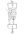
出力ライン8,9を持つ燃料電池スタック7が、出力ライン両端に直接、あるいはDC/DCコンバータ22を介して接続された、スーパーキャパシタ10もしくはバッテリ10aのバンクを有する。燃料電池スタックは改質器13もしくは水素源13aのいずれかから燃料を受け入れる。電力はパワーコンディショニングシステム15を通して負荷16へと供給され、すべてコントローラ19の制御下にある。スーパーキャパシタもしくはバッテリは、突発的な負荷減少の際には過剰電力から余剰の電荷を受け入れ、また突発的な負荷需要の増加の際には電力出力ライン8,9に電荷を供給する。一実施例では、スーパーキャパシタもしくはバッテリの電圧が常に燃料電池スタックの電圧に追従し、これにより対応する電荷を供給、受入する。DC/DCコンバータを用いることにより、スーパーキャパシタもしくはバッテリは燃料電池スタック電圧の数倍もしくは分数倍の電圧で作動し、過渡状態への応答を補助するように電圧を急上昇しうる。 A fuel cell stack 7 having output lines 8 and 9 has a bank of supercapacitors 10 or batteries 10a connected to both ends of the output lines directly or via a DC / DC converter 22. The fuel cell stack receives fuel from either the reformer 13 or the hydrogen source 13a. Power is supplied to the load 16 through the power conditioning system 15 and is all under the control of the controller 19. The supercapacitor or battery accepts surplus charges from excess power in the event of a sudden load decrease, and supplies charges to the power output lines 8, 9 in the event of a sudden increase in load demand. In one embodiment, the voltage on the supercapacitor or battery always follows the voltage on the fuel cell stack, thereby supplying and receiving the corresponding charge. By using a DC / DC converter, the supercapacitor or battery can operate at a voltage several times or a fraction of the fuel cell stack voltage, and the voltage can be ramped up to aid in response to transient conditions.
Description
本発明は燃料電池スタックと並列に電気的に接続されたバッテリもしくはスーパーキャパシタのバンクを有する燃料電池発電装置に関し、負荷増加の過渡時にエネルギーを供給し、負荷減少の過渡時にエネルギーを吸収するものである。 The present invention relates to a fuel cell power generator having a battery or supercapacitor bank electrically connected in parallel with a fuel cell stack, and supplies energy during a load increase transient and absorbs energy during a load decrease transient. is there.
燃料電池スタックアセンブリの通常作動中、突発的な負荷の増加が起こったとき、燃料電池スタックアセンブリの要求された電力を供給する能力は、本質的には燃料流れ場における燃料滞留量と相関する。燃料流れ場が、燃料電池膜により多くの燃料が接するように設計されれば、燃料電池スタックアセンブリはより高い負荷増加過渡的応答能力を持つ。しかしながら、燃料流れ場に増加分の燃料を供給することは、チャネル間のリブを薄くするという犠牲を払って燃料チャネルを大きくすることを必要とし、これにより燃料電池スタックの強度は下がり、組み立ておよびその他の取り扱い中の燃料電池クラッキングの原因となりうる。一方、各々の燃料電池の容積をより大型化することは、燃料電池発電装置が電気自動車に電気を供給するといった、自動車への応用には通常不適切である。 During normal operation of the fuel cell stack assembly, when a sudden load increase occurs, the ability of the fuel cell stack assembly to supply the required power is essentially correlated with the amount of fuel stagnation in the fuel flow field. If the fuel flow field is designed so that more fuel is in contact with the fuel cell membrane, the fuel cell stack assembly has a higher load increasing transient response capability. However, supplying an increased amount of fuel to the fuel flow field requires a larger fuel channel at the cost of thinning the ribs between the channels, thereby reducing the strength of the fuel cell stack, assembling and Other causes of fuel cell cracking during handling. On the other hand, increasing the volume of each fuel cell is usually unsuitable for automotive applications, such as the fuel cell power generator supplying electricity to an electric vehicle.
90%以上のオーダの、最大燃料利用率を達成するために、燃料リサイクルが用いられうる。このような場合、燃料流れ場に余剰の水素滞留がないことが不可欠である。したがって、システム効率向上のための燃料リサイクルの使用は、負荷増加過渡応答能力の縮小といった犠牲を伴う。 To achieve maximum fuel utilization, on the order of 90% or higher, fuel recycling can be used. In such cases, it is essential that there is no excess hydrogen retention in the fuel flow field. Thus, the use of fuel recycling to improve system efficiency comes at the cost of reduced load increase transient response capability.
通常作動中の燃料電池発電装置は突発的な負荷減少をこうむることがある。バルブやソレノイドを含む燃料処理システムは、こうした需要負荷減少に対する応答が遅れるため、燃料電池スタック内では多量の余剰水素が消費されていない。余剰水素はある種類の下流燃焼器に流入することがある。負荷減少過渡状態下の燃焼器への供給水素量は、通常燃焼器が対応しうる水素量の数倍に達しうる。装置にダメージをもたらすことなく、余剰水素を消費できるようにするために、容積や燃焼能力を増加しなければならないが、これは燃料電池発電装置全体の容積とコストを増加させうる。もし余剰の水素を単に排出するだけならば、水素を1パーセント以下に希釈するなど、安全に対処されなければならない。これは燃料処理システム全体の換気能力の増加を必要とする。燃料制御応答率に対するより厳格な制御は余剰水素の問題を緩和しうるが、決して問題を全体的に排除することはできず、燃料電池システムに多大な経費を計上することになる。 A normally operating fuel cell generator may experience a sudden load reduction. A fuel processing system including valves and solenoids has a delayed response to such a decrease in demand load, so that a large amount of surplus hydrogen is not consumed in the fuel cell stack. Surplus hydrogen may enter certain types of downstream combustors. The amount of hydrogen supplied to the combustor under a load reduction transient can reach several times the amount of hydrogen that a normal combustor can accommodate. In order to be able to consume surplus hydrogen without damaging the device, the volume and combustion capacity must be increased, which can increase the overall volume and cost of the fuel cell power plant. If surplus hydrogen is simply discharged, it must be handled safely, such as diluting hydrogen below 1 percent. This requires an increase in the ventilation capacity of the entire fuel processing system. Tighter control over the fuel control response rate can alleviate the problem of surplus hydrogen, but the problem cannot be eliminated entirely and will add significant expense to the fuel cell system.
突発的な負荷減少に起因する余剰燃料の問題は米国特許第6,572,993号に参照されている。しかしながら、この特許のシステムは、バッテリパックや複数のキャパシタもしくは複数のスーパーキャパシタのような蓄電装置を、80%といった、最大充電レベルにおける所定の割合の、ほぼ一律のレベルで稼動している。突発的な負荷減少に応じて、エネルギー蓄電装置は燃料電池によって生み出された余剰のエネルギーを、アノードに入る燃料量がエネルギー蓄電装置の必要とされないレベルを下回るまで吸収する。その時点で、エネルギー蓄電装置は元の所定のレベルに戻るように余剰のエネルギーを放出する。負荷が以前の通常レベルに戻ると、エネルギー蓄電装置は所望の電力出力レベルを維持するために余剰のエネルギーを供給する。より多くの燃料がアノードに供給されるにつれ、電力およびエネルギー蓄電装置の蓄電レベルは通常のレベルに戻りうる。 The problem of surplus fuel due to sudden load reduction is referenced in US Pat. No. 6,572,993. However, the system of this patent operates a power storage device such as a battery pack, a plurality of capacitors, or a plurality of supercapacitors at a substantially uniform level at a predetermined rate at the maximum charge level, such as 80%. In response to a sudden load decrease, the energy storage device absorbs excess energy generated by the fuel cell until the amount of fuel entering the anode falls below an unneeded level of the energy storage device. At that time, the energy storage device releases surplus energy so as to return to the original predetermined level. When the load returns to the previous normal level, the energy storage device supplies surplus energy to maintain the desired power output level. As more fuel is supplied to the anode, the power and energy storage levels of the energy storage device can return to normal levels.
したがって、前記の特許は、定常状態が最優先されるシステムを有し、負荷の過渡的な下降には、エネルギー蓄電装置が、余剰のエネルギーを吸収し、その後放出するよう制御され、過渡状態の終わりには余剰のエネルギーを供給し、その後もとの所定のレベルに戻ることにより対応している。 Therefore, the patent has a system in which the steady state is given the highest priority, and in the transient drop of the load, the energy storage device is controlled to absorb the excess energy and then release it. At the end, surplus energy is supplied and then returned to the original predetermined level.
キャパシタあるいはスーパーキャパシタが蓄電装置として使用される場合には、電荷は電圧と電気容量との積に等しいものであり、電荷は常に最大充電量の80%といった、一定の割合に設定されているため、前記特許のシステムは他の一切によらず、常に一定した、特定の、所定の電圧に設定されている。バッテリが用いられる場合には、任意の電荷レベルにおいて電圧は一定している。 When a capacitor or supercapacitor is used as a power storage device, the charge is equal to the product of the voltage and the electric capacity, and the charge is always set at a constant rate such as 80% of the maximum charge amount. The patented system is set to a constant, specific and predetermined voltage, regardless of anything else. When a battery is used, the voltage is constant at any charge level.
前述のシステムは、電力を電気自動車に供給する燃料電池発電装置のような、要求が常に著しく変化する燃料電池発電装置の最新の応用分野の需要を満たさない。 Such systems do not meet the demands of modern applications of fuel cell power generators, whose demands are constantly changing, such as fuel cell power generators that supply power to electric vehicles.
本発明は、突発的な負荷の増加や減少に即座に対応しうる燃料電池発電装置と、燃料電池構造を弱体化させることなく、突発的な負荷の減少に対応する燃料電池スタックの向上された能力と、炭化水素燃料を燃料電池燃料として使用する水素へと転換し、緩やかに応答するセンサやバルブを利用しうる改質器の提供と、燃料電池スタック内の水素の費用効果の高い生産、利用と、改質器や燃料電池スタックにより炭化水素燃料を電気に変換する改善された装置と、を含む。 The present invention provides an improved fuel cell power generator capable of immediately responding to sudden increases and decreases in load and a fuel cell stack capable of responding to sudden decreases in load without weakening the fuel cell structure. Capability and conversion of hydrocarbon fuel to hydrogen for use as fuel cell fuel, providing a reformer that can utilize sensors and valves that respond slowly, and cost-effective production of hydrogen in the fuel cell stack, And improved devices for converting hydrocarbon fuels into electricity by means of reformers and fuel cell stacks.
本発明は、適切な装置や作動方法が用いられることを条件として、広く変動する負荷への対応に必要な水素量の調節のみならず、必要なパワーコンディショニングの調節も即座に行われる必要はないが、代わりに燃料電池出力で、即座に電気的に吸収されうることの実現を前提としている。 The present invention does not require immediate adjustment of the necessary power conditioning as well as the adjustment of the amount of hydrogen required to accommodate widely varying loads, provided that appropriate equipment and operating methods are used. However, it is assumed that the fuel cell output can be instantly absorbed by the fuel cell output instead.
本発明に従い、燃料電池発電装置の電気出力が、電圧変換との積極的な制御スイッチングを通して、あるいは、直接的かつ受動的に、スーパーキャパシタもしくはバッテリのバンクのような蓄電装置により制御される。スーパーキャパシタもしくはバッテリのバンクは、燃料電池スタックと、負荷を供給する出力パワーコンディショニングシステムとの間に接続される。 In accordance with the present invention, the electrical output of the fuel cell power plant is controlled by a power storage device, such as a supercapacitor or a bank of batteries, either through active control switching with voltage conversion or directly and passively. A bank of supercapacitors or batteries is connected between the fuel cell stack and the output power conditioning system that supplies the load.
本発明の一形態に従い、蓄電バンクが燃料電池スタックの電気出力の両端に直接接続され、蓄電装置の電圧が燃料電池スタックの電圧出力に、制御を介さず常に、完全に従うことができるようになっている。これにより蓄電装置が、蓄電装置の電圧を燃料電池スタックの電圧と実質的に同一に、ごくわずかの取るに足らないほどの遅れでもって維持するように、必要に応じて自動的に電荷を供給、受入する。 In accordance with one aspect of the present invention, the storage bank is directly connected to both ends of the electrical output of the fuel cell stack, so that the voltage of the storage device can always completely follow the voltage output of the fuel cell stack without any control. ing. This allows the battery to automatically supply charge as needed to keep the battery voltage substantially the same as the fuel cell stack voltage with a negligible delay. , Accept.
本発明の別の一形態に従い、スーパーキャパシタもしくはバッテリのバンクのような蓄電装置の電圧が、再生式DC/DCコンバータにより燃料電池スタックの電圧から分離されている。 In accordance with another aspect of the invention, the voltage of a power storage device, such as a supercapacitor or battery bank, is separated from the voltage of the fuel cell stack by a regenerative DC / DC converter.
燃料電池スタックの電力側の電力不足や余剰に対処することにより、燃料電池スタックへの水素の生産や利用を、コストの増加や、装置の危機的状況、大気汚染などなく、電力負荷過渡状態よりもずっとゆっくりと調整することができ、グリッドや他の負荷を給電する電力変換装置を、より少ない制約の、低コストのよりよい効率、小さい範囲で稼動することができる。 By dealing with power shortages and surpluses on the power side of the fuel cell stack, the production and use of hydrogen to the fuel cell stack can be achieved more easily than the power load transient state without increasing costs, equipment crisis, air pollution, etc. Can be adjusted much more slowly and power converters that feed grids and other loads can be operated with fewer constraints, lower cost, better efficiency, and smaller range.
本発明に従い、図1を参照すると、燃料電池発電装置6は、スーパーキャパシタバンク10のような蓄電装置とともに電力出力ライン8,9を有する燃料電池スタック7を含み、このスーパーキャパシタバンク10が、燃料電池スタック7と並列に出力ライン8,9間に直接接続されている。本実施例では、燃料電池スタック7は、燃料源14からの炭化水素燃料を転換する改質器13から通路11を通して水素含有燃料を供給されており、この燃料源14は例えば、2003年2月18日に出願された同時係属中の米国特許出願番号10/369,359に開示されているような触媒部分酸化改質器システム、あるいは無害の水素高含有燃料を燃料電池スタックへ供給するのに適した他の改質器でもよい。
In accordance with the present invention and referring to FIG. 1, a fuel
出力ライン8,9の電力が、電力を負荷16に供給する、通常のパワーコンディショニングシステム15によって用途に応じて制御されており、この負荷16は、グリッド、電気自動車モータ、あるいは他のあらゆる負荷でもよい。本文で用いられているように、用語「Aload@」は、負荷16、もしくはパワーコンディショニングシステム15と負荷16を意味しうる。燃料電池スタック7と並列にスーパーキャパシタバンク10を用いることにより、負荷16が減少すると、コントローラ19が燃料の燃料供給源14への供給を減少させる。しかしながら、燃料電池スタックや燃料供給システムには余剰の水素が存在する。負荷16が減少するにつれ、電力出力ライン8,9の電圧は増加する。これによりスーパーキャパシタの電圧を増加させ、電荷を増やす。スーパーキャパシタへの電荷の増加が余剰の水素からの過剰な電力を消費し、燃料電池スタック排気システム換気やバーナ(図示せず)の負担を軽減する。
The power of the
負荷16が増加すると、コントローラ19は、他の調節に加えて、通常の方法で燃料吸入バルブを開けることにより燃料の燃料電池スタックへの供給を増加させ、改質器の吸入バルブを開けることにより炭化水素燃料の改質器への供給を増加させる。しかしながら、燃料量を新たに必要なレベルに増量できる前は、燃料電池スタックは負荷に対処するように適切に稼動しない。燃料電池スタックによって供給される電流レベルの増加により、平均電池電圧は低下し、スーパーキャパシタバンク10の電圧を低下させ、電荷をスーパーキャパシタバンクから流出させ、これによりパワーコンディショニングシステム15へと電流を供給する。したがって、スーパーキャパシタバンク10は、燃料電池トラック7の電力出力と直接並列に接続されることにより、受動的、かつ自動的に制御される。本発明により、燃料電池スタック電気出力8,9の電圧のみに応じて、負荷16の電力需要をみたすように、スーパーキャパシタバンク10からパワーコンディショニングシステム15へと電流が流れる。
As the
コントローラ19は最終的に、改質器13により生産される水素量と、通路11より燃料電池スタック7のアノードへ取り込まれる水素高含有燃料量を増量させる。これにより、スーパーキャパシタバンク10は、本発明により、単にライン8,9の燃料電池スタック出力電圧に常に追従し、これにより負荷に関する燃料平衡の過渡、回復のあらゆる段階における、あらゆる負荷の変動に継続して応答することができる。図1の実施例では、この応答が受動的に行われているが、これはスーパーキャパシタバンクが燃料電池スタック7の出力ライン8,9間に、いかなる制御の介在なく、直接並列に接続されているためである。したがって、本発明の実施例では、スーパーキャパシタバンクの電荷レベルを回復させるいかなる制御もいかなる形式において一切必要なく、自動的に受動的に行われる。
The
図1の実施例では、スーパーキャパシタバンク10は受動的であり、すなわち、スーパーキャパシタバンクは、単にライン8,9の電圧がスーパーキャパシタバンクの電圧より高いか低いかに依存して電荷を受け入れたり放出したりする。スーパーキャパシタバンクは常に燃料電池スタックの電圧に従うため、実際の過渡状態の間を除き、常に燃料電池スタックの電圧となり、したがってスーパーキャパシタバンクは、電荷を受け入れることにより高い電圧に、あるいは電荷を放出することにより低い電圧に、それぞれ応答する準備が整っている。
In the embodiment of FIG. 1, the
本発明の任意の実施に適合される必要に応じて、図2に示すように、スーパーキャパシタバンクの充電放電機能を、通常の再生型DC/DCコンバータ22により拡張することができる。DC/DCコンバータは、過渡状態が極端に急速で大きく、スーパーキャパシタバンクの電圧が負荷を増加させるのに十分高くない状況や、同様に、かなり低い電圧への電圧変化が大きいためにスーパーキャパシタバンクがより高い電圧に上昇しない限り電荷を受け入れないような状況において最も有利である。コンバータ22の使用によりさらに大きなエネルギーの除去(すなわち、より深い放電)を可能にする。
Depending on the needs adapted to any implementation of the present invention, the charge and discharge function of the supercapacitor bank can be extended by a conventional regenerative DC /
図2の実施例では、DC/DCコンバータ22を利用することにより、スーパーキャパシタバンク10は、例えば、実質的にライン8,9の燃料電池スタック電圧とは異なる電圧で作動しうる。例としては、通常作動中、燃料電池スタックが約250ボルトDCから約450ボルトDCの範囲の電圧で作動する一方、スーパーキャパシタバンク10は数百ボルトに達する電圧の範囲で作動しうる。図2の実施例では、DC/DCコンバータが電圧を燃料電池スタック電圧の数倍あるいは分数倍の電圧に変換できるだけでなく、より多くの電荷(より増加した電流)をスーパーキャパシタバンクから放出させるために、コントローラが、スーパーキャパシタバンクの隣のコンバータ側の電圧を、燃料電池スタックライン8,9両端の電圧低下を数倍以上に拡大して低下させることにより、極端に鋭い過渡状態に応答して急激に電圧を上昇させることができる。
In the embodiment of FIG. 2, by utilizing the DC /
DC/DCコンバータ22の蓄電装置側の電圧は概して燃料電池スタック電圧の分数倍となる。コントローラ19はDC/DCコンバータを、ライン8,9間の電圧のような負荷に関する電圧、負荷16の電圧、もしくはスタック7内部のサブスタック電圧(例えば電池の集合体の電圧)のいずれかに応答して制御しうる。
The voltage on the power storage device side of the DC /
図3はまた、水素源が、改質器13を用いる代わりに、水素タンク13aである例を示している。
FIG. 3 also shows an example in which the hydrogen source is a
本実施例では、通常のパワーコンディショニングシステム15が燃料電池スタック7から出力ライン8,9を通して電力を受け取り、負荷16へ電力を供給している。パワーコンディショニングシステムを必要としないあるシステムでは、本発明が負荷16を直接運転するように活用されうる。
In this embodiment, a normal
図4は電気エネルギー蓄電装置がバッテリのバンク10Aを含みうることを示している。
FIG. 4 shows that the electrical energy storage device can include a bank of
Claims (7)
前記燃料電池スタックに接続された燃料源(13,14)と、
前記燃料電池スタックへの供給燃料を制御するコントローラ(19)と、
よりなる燃料電池発電装置(6)であって、
(c)前記燃料電池スタックと並列に、前記電力出力ライン間に直接接続されることにより、前記燃料電池スタックの電圧が、常に前記電力出力ライン間の電圧に追従し、実質的に常に前記電力出力ライン間の電圧と同じ電圧となる電気エネルギー蓄電装置(10)もしくは、
(d)前記電力出力ライン間に、DC/DCコンバータ(22)と直列に接続されている電気エネルギー蓄電装置(10)
のいずれかを備えていることを特徴とする燃料電池発電装置(6)。 A fuel cell stack (7) having a power output line (8, 9) connected to either (a) a load (16) or (b) a power conditioning system (15) supplying the load; )When,
A fuel source (13, 14) connected to the fuel cell stack;
A controller (19) for controlling fuel supplied to the fuel cell stack;
A fuel cell power generator (6) comprising:
(C) By being directly connected between the power output lines in parallel with the fuel cell stack, the voltage of the fuel cell stack always follows the voltage between the power output lines, and substantially always An electrical energy storage device (10) having the same voltage as the voltage between the output lines, or
(D) An electric energy storage device (10) connected in series with a DC / DC converter (22) between the power output lines.
A fuel cell power generator (6) comprising any of the above.
前記燃料電池スタックと連結された電気エネルギー蓄電装置(10)を備えるとともに、
前記電気エネルギー蓄電装置に、常に前記電力出力ライン間の電圧の(a)実質的に数倍、もしくは(b)実質的に分数倍のいずれかの電圧を提供する手段(22)と、
前記負荷に関連した電圧に応答して、前記電気エネルギー蓄電装置に供給される電圧を制御する手段(19)と、
を備えたことを特徴とする燃料電池発電装置(6)。 A fuel cell power generator (6) having a fuel cell stack (7) with power output lines (8, 9) and supplying power to a load (16),
An electrical energy storage device (10) connected to the fuel cell stack;
Means (22) for providing the electrical energy storage device with a voltage that is always (a) substantially several times the voltage across the power output line, or (b) substantially a fractional multiple,
Means (19) for controlling a voltage supplied to the electrical energy storage device in response to a voltage associated with the load;
A fuel cell power generator (6) comprising:
前記電気エネルギー蓄電装置に、常に前記電力出力ライン間の電圧の(a)実質的に数倍、もしくは(b)実質的に分数倍のいずれかの電圧を供給し(22)、
前記負荷に関連した電圧に応答して、前記電気エネルギー蓄電装置に供給される電圧を制御する(19)ことを特徴とする方法。 Fuel cell power generation comprising a fuel cell stack (7) having a power output line (8, 9) for supplying power to a load (16), and an electric energy storage device (10) connected to the fuel cell stack A method for operating a device (6), comprising:
Supplying the electrical energy storage device with a voltage that is always (a) substantially several times the voltage between the power output lines, or (b) substantially a fractional multiple (22),
A method of controlling a voltage supplied to the electrical energy storage device in response to a voltage associated with the load (19).
前記電気エネルギー蓄電装置を前記燃料電池スタックと並列に、前記電力出力ライン間に直接接続し、
前記電気エネルギー蓄電装置の電圧を、前記電力出力ライン両端の電圧に追従させ、これにより前記蓄電装置の電圧が常に前記電力出力ライン間の電圧に従い、実質的に常に前記電力出力ライン間の電圧と同じ電圧となることを特徴とする方法。
Fuel cell power generation comprising a fuel cell stack (7) having a power output line (8, 9) for supplying power to a load (16), and an electric energy storage device (10) connected to the fuel cell stack A method for operating a device (6), comprising:
Connecting the electrical energy storage device in parallel with the fuel cell stack and directly between the power output lines;
The voltage of the electric energy storage device is made to follow the voltage across the power output line, whereby the voltage of the power storage device always follows the voltage between the power output lines, and is substantially always the voltage between the power output lines. A method characterized by having the same voltage.
Applications Claiming Priority (2)
| Application Number | Priority Date | Filing Date | Title |
|---|---|---|---|
| US10/717,089 US7087329B2 (en) | 2003-11-19 | 2003-11-19 | Electric storage augmentation of fuel cell system transient response |
| PCT/US2004/038719 WO2005053061A2 (en) | 2003-11-19 | 2004-11-17 | Electric storage augmentation of fuel cell system transient response |
Publications (1)
| Publication Number | Publication Date |
|---|---|
| JP2007511891A true JP2007511891A (en) | 2007-05-10 |
Family
ID=34574519
Family Applications (1)
| Application Number | Title | Priority Date | Filing Date |
|---|---|---|---|
| JP2006541375A Pending JP2007511891A (en) | 2003-11-19 | 2004-11-17 | Storage expansion of fuel cell system transient response |
Country Status (4)
| Country | Link |
|---|---|
| US (1) | US7087329B2 (en) |
| EP (1) | EP1692736B1 (en) |
| JP (1) | JP2007511891A (en) |
| WO (1) | WO2005053061A2 (en) |
Cited By (4)
| Publication number | Priority date | Publication date | Assignee | Title |
|---|---|---|---|---|
| JP2007109609A (en) * | 2005-10-17 | 2007-04-26 | Omron Corp | Charge / discharge device for fuel cell system |
| KR101143867B1 (en) | 2008-04-24 | 2012-05-24 | 호발츠벨케 도이췌 벨프트 게엠베하 | Method for energy supply |
| US10135282B2 (en) | 2014-12-04 | 2018-11-20 | Omron Corporation | Storage battery control apparatus, power storage system, and method for charging storage battery |
| CN109823235A (en) * | 2019-02-20 | 2019-05-31 | 中国科学技术大学 | Energy management system for battery, supercapacitor and fuel cell hybrid energy storage device |
Families Citing this family (14)
| Publication number | Priority date | Publication date | Assignee | Title |
|---|---|---|---|---|
| US6991864B2 (en) | 2003-09-23 | 2006-01-31 | Utc Fuel Cells, Llc | Storage of fuel cell energy during startup and shutdown |
| ITTO20040054A1 (en) * | 2004-02-04 | 2004-05-04 | Fiat Ricerche | INNOVATIVE ARCHITECTURES OF ENERGY GENERATION AND DISTRIBUTION SYSTEMS ON BOARD MOTOR VEHICLES |
| US7700210B2 (en) * | 2005-05-10 | 2010-04-20 | Bloom Energy Corporation | Increasing thermal dissipation of fuel cell stacks under partial electrical load |
| US20070285048A1 (en) * | 2006-06-12 | 2007-12-13 | Leach David H | Fuel cell charger interface with multiple voltage outputs for portable devices |
| US20080277175A1 (en) * | 2007-05-07 | 2008-11-13 | Ise Corporation | Fuel Cell Hybrid-Electric Heavy-Duty Vehicle Drive System and Method |
| DE102007049081A1 (en) * | 2007-10-12 | 2008-07-24 | Daimler Ag | Fuel cell system operating method for use in motor vehicle, involves regulating intermediate circuit voltage in electrical power line to preset value, where voltage is provided by fuel cell system and is regulated by regulator |
| US20090179609A1 (en) * | 2008-01-11 | 2009-07-16 | Gm Global Technology Operations, Inc. | HV Battery Equalization Charge During Driving Operation in Fuel Cell Hybrid Vehicles |
| US7952231B1 (en) * | 2008-10-31 | 2011-05-31 | Netapp, Inc. | Method and system for providing supplemental power |
| US8553381B2 (en) | 2011-05-27 | 2013-10-08 | Hamilton Sundstrand Corporation | Gradually reducing resistive clamp |
| US11127538B2 (en) | 2017-02-20 | 2021-09-21 | The Research Foundation For The State University Of New York | Multi-cell multi-layer high voltage supercapacitor apparatus including graphene electrodes |
| US12257889B2 (en) * | 2020-05-05 | 2025-03-25 | Volvo Truck Corporation | Locking arrangement for a mounting system for an energy storage system on a vehicle |
| US20220203844A1 (en) * | 2020-12-30 | 2022-06-30 | Cummins Inc. | Power generation systems and methods for controlling cascaded batteries and fuel cells with supercapacitors |
| WO2023040919A1 (en) * | 2021-09-20 | 2023-03-23 | The Hong Kong Polytechnic University | Energy storage systems and ammonia-powered electric vehicles including the same |
| US12280679B2 (en) | 2021-12-13 | 2025-04-22 | Cummins Inc. | Fuel cell powertrain systems and methods for power split and allocation in fuel cell powertrain systems |
Citations (4)
| Publication number | Priority date | Publication date | Assignee | Title |
|---|---|---|---|---|
| JP2001339872A (en) * | 1995-04-14 | 2001-12-07 | Hitachi Ltd | Driving device and control method for electric vehicle with hybrid battery |
| JP2002112408A (en) * | 2000-09-27 | 2002-04-12 | Nissan Motor Co Ltd | Power control device for fuel cell vehicle |
| JP2003164063A (en) * | 2001-11-27 | 2003-06-06 | Osaka Gas Co Ltd | Power supply |
| US20030201674A1 (en) * | 2000-07-28 | 2003-10-30 | International Power System, Inc. | DC to DC converter and power management system |
Family Cites Families (17)
| Publication number | Priority date | Publication date | Assignee | Title |
|---|---|---|---|---|
| JP2989353B2 (en) * | 1991-11-29 | 1999-12-13 | 三洋電機株式会社 | Hybrid fuel cell system |
| JP3687991B2 (en) * | 1994-02-24 | 2005-08-24 | 株式会社エクォス・リサーチ | Hybrid power supply |
| US5777454A (en) * | 1996-05-29 | 1998-07-07 | Peco Ii, Inc. | Back-up battery management system for a DC power supply |
| US6484830B1 (en) * | 2000-04-26 | 2002-11-26 | Bowling Green State University | Hybrid electric vehicle |
| JP3662872B2 (en) * | 2000-11-17 | 2005-06-22 | 本田技研工業株式会社 | Fuel cell power supply |
| US6572993B2 (en) | 2000-12-20 | 2003-06-03 | Visteon Global Technologies, Inc. | Fuel cell systems with controlled anode exhaust |
| JP2002324562A (en) * | 2001-04-27 | 2002-11-08 | Mitsubishi Heavy Ind Ltd | Fuel cell power-generating system and operating method therefor |
| JP4130319B2 (en) * | 2001-07-10 | 2008-08-06 | 本田技研工業株式会社 | Fuel cell control device |
| US6794844B2 (en) * | 2001-08-31 | 2004-09-21 | Visteon Global Technologies, Inc. | Method and system for fuel cell control |
| US6737762B2 (en) * | 2001-10-26 | 2004-05-18 | Onan Corporation | Generator with DC boost for uninterruptible power supply system or for enhanced load pickup |
| US6841275B2 (en) * | 2001-12-14 | 2005-01-11 | Ballard Power Systems Inc. | Method and apparatus for controlling voltage from a fuel cell system |
| KR20030050139A (en) * | 2001-12-18 | 2003-06-25 | 현대자동차주식회사 | Electric power system on fuel cell hybrid electric vehicle |
| US6881509B2 (en) * | 2001-12-19 | 2005-04-19 | Abb Research Ltd. | Fuel cell system power control method and system |
| JP3744456B2 (en) * | 2002-04-08 | 2006-02-08 | 日産自動車株式会社 | Control device for vehicle equipped with fuel cell |
| JP3911435B2 (en) | 2002-04-11 | 2007-05-09 | トヨタ自動車株式会社 | Power supply system and control method thereof |
| KR100460881B1 (en) * | 2002-06-28 | 2004-12-09 | 현대자동차주식회사 | System and method for controlling power conversion of fuel cell hybrid electric vehicle |
| KR20040009370A (en) * | 2002-07-23 | 2004-01-31 | 현대자동차주식회사 | Method of controlling output power of fuel cell for fuel cell hybrid electric vehicle |
-
2003
- 2003-11-19 US US10/717,089 patent/US7087329B2/en not_active Expired - Lifetime
-
2004
- 2004-11-17 WO PCT/US2004/038719 patent/WO2005053061A2/en not_active Ceased
- 2004-11-17 EP EP04811433.4A patent/EP1692736B1/en not_active Expired - Lifetime
- 2004-11-17 JP JP2006541375A patent/JP2007511891A/en active Pending
Patent Citations (4)
| Publication number | Priority date | Publication date | Assignee | Title |
|---|---|---|---|---|
| JP2001339872A (en) * | 1995-04-14 | 2001-12-07 | Hitachi Ltd | Driving device and control method for electric vehicle with hybrid battery |
| US20030201674A1 (en) * | 2000-07-28 | 2003-10-30 | International Power System, Inc. | DC to DC converter and power management system |
| JP2002112408A (en) * | 2000-09-27 | 2002-04-12 | Nissan Motor Co Ltd | Power control device for fuel cell vehicle |
| JP2003164063A (en) * | 2001-11-27 | 2003-06-06 | Osaka Gas Co Ltd | Power supply |
Cited By (5)
| Publication number | Priority date | Publication date | Assignee | Title |
|---|---|---|---|---|
| JP2007109609A (en) * | 2005-10-17 | 2007-04-26 | Omron Corp | Charge / discharge device for fuel cell system |
| KR101143867B1 (en) | 2008-04-24 | 2012-05-24 | 호발츠벨케 도이췌 벨프트 게엠베하 | Method for energy supply |
| US10135282B2 (en) | 2014-12-04 | 2018-11-20 | Omron Corporation | Storage battery control apparatus, power storage system, and method for charging storage battery |
| CN109823235A (en) * | 2019-02-20 | 2019-05-31 | 中国科学技术大学 | Energy management system for battery, supercapacitor and fuel cell hybrid energy storage device |
| CN109823235B (en) * | 2019-02-20 | 2021-10-01 | 中国科学技术大学 | Energy management system for battery, supercapacitor and fuel cell hybrid energy storage device |
Also Published As
| Publication number | Publication date |
|---|---|
| WO2005053061A3 (en) | 2005-06-30 |
| US20050106432A1 (en) | 2005-05-19 |
| EP1692736A2 (en) | 2006-08-23 |
| EP1692736A4 (en) | 2009-06-24 |
| WO2005053061A2 (en) | 2005-06-09 |
| EP1692736B1 (en) | 2013-10-02 |
| US7087329B2 (en) | 2006-08-08 |
Similar Documents
| Publication | Publication Date | Title |
|---|---|---|
| JP2007511891A (en) | Storage expansion of fuel cell system transient response | |
| JP3657582B2 (en) | Fuel cell control system | |
| US7597976B2 (en) | Floating base load hybrid strategy for a hybrid fuel cell vehicle to increase the durability of the fuel cell system | |
| JP4778492B2 (en) | Method for improving power rise transient response in fuel cell systems | |
| US8837179B2 (en) | Alternating current power supply device and method of controlling same | |
| Kisacikoglu et al. | Fuzzy logic control of a fuel cell/battery/ultra-capacitor hybrid vehicular power system | |
| CN102470810A (en) | Circuit arrangement for an on-board system | |
| JPWO2017010069A1 (en) | Fuel cell system and operation method thereof | |
| US8427097B2 (en) | Hybrid electrical power source | |
| JP2014535138A (en) | Method for controlling the operation of a hybrid system | |
| JP2015220889A (en) | Power supply system | |
| US7829229B1 (en) | Power control for hybrid fuel cell systems | |
| US20120308850A1 (en) | Method for managing the operation of a hybrid system | |
| US7808129B2 (en) | Fuel-cell based power generating system having power conditioning apparatus | |
| US20220173612A1 (en) | System for supplying energy to electrically operated mining machines | |
| Hawke et al. | A modular fuel cell with hybrid energy storage | |
| JP4978019B2 (en) | Fuel cell system | |
| KR20250050272A (en) | Flow battery system that can be linked with renewable energy source | |
| JP2000188120A (en) | Fuel cell system | |
| Swarnkar et al. | Performance analysis of hybrid fuel cell/battery/supercapacitor electric vehicle for different battery state of charge levels | |
| KR20230069013A (en) | Hybrid fuel cell system for load following and backup in a microgrid and method of operating thereof | |
| JP2005123110A (en) | Fuel cell power supply system and output control method thereof | |
| Latha et al. | Investigation of various operating modes of fuelcell/ultracapacitor/multiple converter based hybrid system | |
| TW559602B (en) | Electric power output control system of compound type fuel-cell electric vehicle | |
| Pany et al. | Power management of fuel cell and battery fed DC motor drive for electric vehicle application |
Legal Events
| Date | Code | Title | Description |
|---|---|---|---|
| A621 | Written request for application examination |
Free format text: JAPANESE INTERMEDIATE CODE: A621 Effective date: 20070828 |
|
| A131 | Notification of reasons for refusal |
Free format text: JAPANESE INTERMEDIATE CODE: A131 Effective date: 20110301 |
|
| A02 | Decision of refusal |
Free format text: JAPANESE INTERMEDIATE CODE: A02 Effective date: 20110809 |