JP2007500465A - High frequency components - Google Patents
High frequency components Download PDFInfo
- Publication number
- JP2007500465A JP2007500465A JP2006521714A JP2006521714A JP2007500465A JP 2007500465 A JP2007500465 A JP 2007500465A JP 2006521714 A JP2006521714 A JP 2006521714A JP 2006521714 A JP2006521714 A JP 2006521714A JP 2007500465 A JP2007500465 A JP 2007500465A
- Authority
- JP
- Japan
- Prior art keywords
- conductive track
- frequency component
- resonator
- conductive
- component according
- Prior art date
- Legal status (The legal status is an assumption and is not a legal conclusion. Google has not performed a legal analysis and makes no representation as to the accuracy of the status listed.)
- Pending
Links
- 239000000758 substrate Substances 0.000 claims abstract description 24
- 230000001939 inductive effect Effects 0.000 claims abstract description 13
- 230000008878 coupling Effects 0.000 claims description 34
- 238000010168 coupling process Methods 0.000 claims description 34
- 238000005859 coupling reaction Methods 0.000 claims description 34
- 239000004020 conductor Substances 0.000 claims description 21
- 239000003990 capacitor Substances 0.000 claims description 15
- 239000000463 material Substances 0.000 claims description 8
- 239000000919 ceramic Substances 0.000 claims description 7
- 230000001965 increasing effect Effects 0.000 claims description 7
- 238000000926 separation method Methods 0.000 claims description 6
- RTAQQCXQSZGOHL-UHFFFAOYSA-N Titanium Chemical compound [Ti] RTAQQCXQSZGOHL-UHFFFAOYSA-N 0.000 claims description 4
- 238000005516 engineering process Methods 0.000 claims description 4
- 239000010409 thin film Substances 0.000 claims description 3
- ZOXJGFHDIHLPTG-UHFFFAOYSA-N Boron Chemical compound [B] ZOXJGFHDIHLPTG-UHFFFAOYSA-N 0.000 claims description 2
- OYPRJOBELJOOCE-UHFFFAOYSA-N Calcium Chemical compound [Ca] OYPRJOBELJOOCE-UHFFFAOYSA-N 0.000 claims description 2
- FYYHWMGAXLPEAU-UHFFFAOYSA-N Magnesium Chemical compound [Mg] FYYHWMGAXLPEAU-UHFFFAOYSA-N 0.000 claims description 2
- 229910052788 barium Inorganic materials 0.000 claims description 2
- DSAJWYNOEDNPEQ-UHFFFAOYSA-N barium atom Chemical compound [Ba] DSAJWYNOEDNPEQ-UHFFFAOYSA-N 0.000 claims description 2
- 229910052454 barium strontium titanate Inorganic materials 0.000 claims description 2
- 229910052797 bismuth Inorganic materials 0.000 claims description 2
- 229910052796 boron Inorganic materials 0.000 claims description 2
- 229910052791 calcium Inorganic materials 0.000 claims description 2
- 239000011575 calcium Substances 0.000 claims description 2
- 229910052749 magnesium Inorganic materials 0.000 claims description 2
- 239000011777 magnesium Substances 0.000 claims description 2
- 239000000696 magnetic material Substances 0.000 claims description 2
- BPUBBGLMJRNUCC-UHFFFAOYSA-N oxygen(2-);tantalum(5+) Chemical compound [O-2].[O-2].[O-2].[O-2].[O-2].[Ta+5].[Ta+5] BPUBBGLMJRNUCC-UHFFFAOYSA-N 0.000 claims description 2
- 229910052761 rare earth metal Inorganic materials 0.000 claims description 2
- 150000002910 rare earth metals Chemical class 0.000 claims description 2
- 239000004065 semiconductor Substances 0.000 claims description 2
- 239000005368 silicate glass Substances 0.000 claims description 2
- 229910052712 strontium Inorganic materials 0.000 claims description 2
- CIOAGBVUUVVLOB-UHFFFAOYSA-N strontium atom Chemical compound [Sr] CIOAGBVUUVVLOB-UHFFFAOYSA-N 0.000 claims description 2
- 229910001936 tantalum oxide Inorganic materials 0.000 claims description 2
- 239000010936 titanium Substances 0.000 claims description 2
- 229910052719 titanium Inorganic materials 0.000 claims description 2
- SNAAJJQQZSMGQD-UHFFFAOYSA-N aluminum magnesium Chemical compound [Mg].[Al] SNAAJJQQZSMGQD-UHFFFAOYSA-N 0.000 claims 1
- 235000012215 calcium aluminium silicate Nutrition 0.000 claims 1
- 230000035515 penetration Effects 0.000 claims 1
- 239000010410 layer Substances 0.000 description 28
- 238000004519 manufacturing process Methods 0.000 description 12
- 230000000694 effects Effects 0.000 description 5
- 230000005540 biological transmission Effects 0.000 description 3
- 229910052751 metal Inorganic materials 0.000 description 3
- 239000002184 metal Substances 0.000 description 3
- 230000004044 response Effects 0.000 description 3
- 230000008901 benefit Effects 0.000 description 2
- 230000001419 dependent effect Effects 0.000 description 2
- 238000010586 diagram Methods 0.000 description 2
- 239000003989 dielectric material Substances 0.000 description 2
- 238000007667 floating Methods 0.000 description 2
- 230000010354 integration Effects 0.000 description 2
- 239000002356 single layer Substances 0.000 description 2
- JCXGWMGPZLAOME-UHFFFAOYSA-N bismuth atom Chemical compound [Bi] JCXGWMGPZLAOME-UHFFFAOYSA-N 0.000 description 1
- 229910052918 calcium silicate Inorganic materials 0.000 description 1
- 239000000378 calcium silicate Substances 0.000 description 1
- 238000004364 calculation method Methods 0.000 description 1
- 230000008859 change Effects 0.000 description 1
- 238000009826 distribution Methods 0.000 description 1
- 230000005672 electromagnetic field Effects 0.000 description 1
- 230000002349 favourable effect Effects 0.000 description 1
- -1 magnesium aluminum calcium Chemical compound 0.000 description 1
- 238000001465 metallisation Methods 0.000 description 1
- 239000000203 mixture Substances 0.000 description 1
- 238000010295 mobile communication Methods 0.000 description 1
- 230000010363 phase shift Effects 0.000 description 1
- 230000005855 radiation Effects 0.000 description 1
- 230000035945 sensitivity Effects 0.000 description 1
- 239000007787 solid Substances 0.000 description 1
- 238000001228 spectrum Methods 0.000 description 1
- 238000003860 storage Methods 0.000 description 1
- 229910052861 titanite Inorganic materials 0.000 description 1
- 229910000859 α-Fe Inorganic materials 0.000 description 1
Images


Classifications
-
- H—ELECTRICITY
- H01—ELECTRIC ELEMENTS
- H01P—WAVEGUIDES; RESONATORS, LINES, OR OTHER DEVICES OF THE WAVEGUIDE TYPE
- H01P1/00—Auxiliary devices
- H01P1/20—Frequency-selective devices, e.g. filters
- H01P1/201—Filters for transverse electromagnetic waves
- H01P1/203—Strip line filters
-
- H—ELECTRICITY
- H01—ELECTRIC ELEMENTS
- H01P—WAVEGUIDES; RESONATORS, LINES, OR OTHER DEVICES OF THE WAVEGUIDE TYPE
- H01P1/00—Auxiliary devices
- H01P1/20—Frequency-selective devices, e.g. filters
- H01P1/201—Filters for transverse electromagnetic waves
- H01P1/203—Strip line filters
- H01P1/20327—Electromagnetic interstage coupling
- H01P1/20336—Comb or interdigital filters
- H01P1/20345—Multilayer filters
-
- H—ELECTRICITY
- H01—ELECTRIC ELEMENTS
- H01P—WAVEGUIDES; RESONATORS, LINES, OR OTHER DEVICES OF THE WAVEGUIDE TYPE
- H01P5/00—Coupling devices of the waveguide type
- H01P5/08—Coupling devices of the waveguide type for linking dissimilar lines or devices
- H01P5/10—Coupling devices of the waveguide type for linking dissimilar lines or devices for coupling balanced lines or devices with unbalanced lines or devices
-
- H—ELECTRICITY
- H01—ELECTRIC ELEMENTS
- H01P—WAVEGUIDES; RESONATORS, LINES, OR OTHER DEVICES OF THE WAVEGUIDE TYPE
- H01P7/00—Resonators of the waveguide type
- H01P7/08—Strip line resonators
-
- H—ELECTRICITY
- H01—ELECTRIC ELEMENTS
- H01P—WAVEGUIDES; RESONATORS, LINES, OR OTHER DEVICES OF THE WAVEGUIDE TYPE
- H01P7/00—Resonators of the waveguide type
- H01P7/08—Strip line resonators
- H01P7/084—Triplate line resonators
Landscapes
- Physics & Mathematics (AREA)
- Electromagnetism (AREA)
- Control Of Motors That Do Not Use Commutators (AREA)
- Filters And Equalizers (AREA)
Abstract
本発明は、複数の誘電体層と、それらの間の、導電トラック構造を有する電極層とで構成された基板を含み、その基板内に少なくとも1つの容量性素子と少なくとも1つの誘導性素子とが形成されている高周波構成部品に関し、対向した導電トラック構造のうちの少なくとも1つの構成が提供され、これらによって容量性素子と誘導性素子とが同時に実現され、それによって、対向している導電トラック構造間のコモン・モード・インピーダンスとプッシュプル・インピーダンスとが少なくとも2倍異なるように調整される。 The present invention includes a substrate composed of a plurality of dielectric layers and an electrode layer having a conductive track structure therebetween, wherein at least one capacitive element and at least one inductive element are included in the substrate. Is provided, wherein at least one of the opposing conductive track structures is provided, whereby a capacitive element and an inductive element are realized simultaneously, thereby opposing conductive tracks The common mode impedance between structures and the push-pull impedance are adjusted to be at least twice different.
Description
本発明は、複数の誘電体層と、それらの間の、導電トラックを有する電極層とで構成された基板を含み、その基板内に少なくとも1つの容量性素子と少なくとも1つの誘導性素子とが形成されている高周波構成部品に関する。このタイプの高周波構成部品は無線回路で使用される。 The present invention includes a substrate composed of a plurality of dielectric layers and an electrode layer having conductive tracks between them, and at least one capacitive element and at least one inductive element are included in the substrate. The present invention relates to a formed high-frequency component. This type of high frequency component is used in radio circuits.
たとえば移動通信装置で使用される無線回路がますます小型化することにより、含まれるあらゆる機能について絶え間ない小型化が必要になる。現代の高周波モジュールでは、集積度をあげるために多層基板を使用する。基板上に作られた各構成部品間の電気的接続だけでなく、たとえばフィルタなどの不可欠な電気的機能が、基板内の導電トラックの適当な構成によって作成される。多くのチップ面積を要し、適度な精度が要求される構造は、しばしば、より経済的に回路板に置き換えることができる。部分的に分布素子が、また部分的に集中素子が使用される。ステップ・インピーダンスを有する配線が、これら述べた2つの両極端なものの間にある。昨今の2つの設計は、回路のサイズが4分の1波長を下回るとき、常に魅力的である。 For example, as radio circuits used in mobile communication devices become increasingly smaller, constant miniaturization is required for all the functions involved. Modern high-frequency modules use a multilayer substrate to increase the degree of integration. In addition to the electrical connections between the components made on the substrate, the essential electrical functions, such as filters, are created by the appropriate configuration of the conductive tracks in the substrate. Structures that require a large amount of chip area and require moderate accuracy can often be more economically replaced with circuit boards. Partly distributed elements and partly lumped elements are used. A wiring with step impedance is between the two extremes mentioned. The two recent designs are always attractive when the circuit size is below a quarter wavelength.
コンデンサを用いてくし形フィルタ内の共振器導体を短くすることが知られている。コンデンサは基板内の平行な平板または外部の構成部品として設計することができる。フィルタ特性は、実質上各共振器間の磁気結合によって決定される。しかし、製造上の理由で各共振器導体が最小距離を維持しなければならない場合、伝導損を小さく保つため導電トラックの幅が大きくなるように選択される場合、または回路サイズを最小限にするために導電トラックが極度に短くされる場合に、結合強度は制限される。知られている平面構成では、多層基板での3次元設計について、新規の可能性を利用することはできない。 It is known to shorten the resonator conductor in a comb filter using a capacitor. Capacitors can be designed as parallel plates in the substrate or as external components. The filter characteristics are substantially determined by the magnetic coupling between the resonators. However, if for manufacturing reasons each resonator conductor must maintain a minimum distance, if the conductive track width is chosen to be large to keep the conduction loss small, or the circuit size is minimized Therefore, the coupling strength is limited when the conductive track is extremely shortened. With the known planar configuration, new possibilities cannot be used for three-dimensional design on multilayer substrates.
経済的な生産プロセスは、通常、金属被膜化寸法または2つの金属層間のミスアライメントでの不確実性などの高い許容度に関連している。このことが、高精度を必要とする回路の集積化または小型化を制限する。G.Passiopolous等、“The RF Impact of Coupled Component Tolerances and Gridded Ground Plates in LTCC Technology and their Design Counter Measures”、Advancing Microelectronics、2003年3月/4月、p.6−10に、コンデンサとコイルとについてのいくつかの対策が記載されている。しかし、インターデジタル・コンデンサを用いても得ることができない高い容量密度を達成しなければならない場合、導電トラック幅のばらつきに対して、これらの手段は無効である。 Economic production processes are usually associated with high tolerances such as uncertainties in metallization dimensions or misalignment between two metal layers. This limits the integration or miniaturization of circuits that require high accuracy. G. Passopoorous et al., “The RF Impact of Coupled Component Tolerances and Gridded Ground Plates in LTCC Technology and the Third Measure Month, 200%. 6-10 describes some countermeasures for capacitors and coils. However, these measures are ineffective with respect to conductive track width variations when high capacitance densities that cannot be obtained using interdigital capacitors must be achieved.
ほとんどすべてのマイクロウェーブ用途で帯域通過フィルタが必要とされる。特に、移動無線システムで使用されている狭帯域の送信回路と受信回路とは、使用周波数帯の外側に見つかるあらゆる干渉信号を抑制するために帯域通過フィルタを必要とする。多くのこうした受動帯域通過フィルタは前述のくし形フィルタと同様の原理に基づき、これらのように、結合された共振器を含む。したがって、各共振器またはそれらの結合において改良を達成することができる場合、それらによって各共振器自体を非常に多くのフィルタ・タイプに変形することができる。 Bandpass filters are required for almost all microwave applications. In particular, narrowband transmission and reception circuits used in mobile radio systems require bandpass filters to suppress any interference signals found outside the used frequency band. Many such passive bandpass filters are based on the same principle as the comb filters described above, and thus include coupled resonators. Thus, if improvements can be achieved in each resonator or their coupling, they can transform each resonator itself into a very large number of filter types.
送信機または受信機の典型的な回路構成は、アダプタ回路網(adaptor network)と平衡トランスとフィルタとを含み、最後に信号をアンテナに引き渡す。このチェーン回路(chain circuit)の1つの不利な点は、多くの個別構成部品が必要になることである。さらに、各機能は個別に最適化されるので、配線には特に阻止帯領域におけるフィードバックによる望ましくない共振が生じることがある。これらの機能をよりコンパクトな回路に集積化するために、いくつかの提案がなされてきた。国際公開第02/093741号パンフレットには、わずかな構成部品で、フィルタと平衡トランスとアダプタ回路網とを同時に含む回路網をどのように構築できるかが記載されている。各共振器は誘導性素子によって結合されるが、それら素子は、基板への集積化の際に多くのスペースを占めるはずである。米国特許第5697088号明細書には、合計4つの4分の1波長共振導体を有する2つの4分の1波長カプラを用いて、フィルタ特性を有する平衡トランスが実現されている。アダプタ回路網は含まれていない。しかし、より少ない共振器を使用することができ、提案された単一層構造では、多層基板を小型化する可能性を利用することができない。 A typical circuit configuration for a transmitter or receiver includes an adapter network, a balanced transformer, and a filter, and finally passes the signal to the antenna. One disadvantage of this chain circuit is that many individual components are required. Furthermore, since each function is individually optimized, the wiring may experience undesirable resonance due to feedback, particularly in the stopband region. Several proposals have been made to integrate these functions into a more compact circuit. International Publication No. WO 02/093741 describes how a network including a filter, a balanced transformer, and an adapter network can be constructed with few components. Each resonator is coupled by an inductive element, which should occupy a lot of space when integrated on a substrate. In US Pat. No. 5,697,088, a balanced transformer having filter characteristics is realized by using two quarter-wave couplers having a total of four quarter-wave resonant conductors. Adapter circuitry is not included. However, fewer resonators can be used, and the proposed single layer structure cannot take advantage of the possibility of downsizing the multilayer substrate.
受動電子機能を最小サイズで多層基板に集積化することができる道筋であって、電気的な仕様を要求することも実現でき、製造許容度への鋭敏性を可能な限り低減することができる道筋を定義することが本発明の目的である。 A path that allows passive electronic functions to be integrated on a multilayer board with a minimum size, can also require electrical specifications, and can reduce sensitivity to manufacturing tolerances as much as possible It is an object of the present invention to define
この目的は、請求項1による高周波構成部品を用いて実現される。有利な諸実施形態が各従属項の主題である。 This object is achieved with a high-frequency component according to claim 1. Advantageous embodiments are the subject of each dependent claim.
本発明によれば、対向した導体構造の少なくとも1つの構成が提供され、これらは、対向する導電トラック構造のコモン・モード・インピーダンスとプッシュプル・インピーダンスとが少なくとも2倍異なるように調整されるという点で、共振器回路の容量性素子と誘導性素子とを同時に実現する。好ましくは、各導体構造は、特定のポイントでまたは固定された電位で互いにリンクする。導電トラック構造を繰り返すことによって多層構造が提供されることは明らかである。対向した金属表面への電流の分布によって、単一層構造の場合よりも低い抵抗損を実現することができる。導体構造は互いに完全にオーバーラップすることがあるが、オーバーラップする必要はない。製造上の見地からは、一般的に層オフセットが生じ、以下でさらに説明する共振周波数へのその影響を低減することができる。また各導体構造のうちの少なくとも1つは、たとえば、給電路、コネクタまたは結合を形成するために、またはより大きいインピーダンス範囲にわたって適合することができるように、他方の構造を超えて延ばすことができる。後者の場合、追加の誘導性素子として延長または接続を使用し、導電トラック幅を削減することなしに、このようにゲートでのより大きい入力インピーダンスを可能にする。特に、分布キャパシタンスを用いると、薄膜技術ではよくあることであるが、結果としてより大きいレベルの設計自由度がもたらされる。 According to the present invention, at least one configuration of opposing conductor structures is provided, which are adjusted so that the common mode impedance and push-pull impedance of the opposing conductive track structures are at least twice different. In that respect, the capacitive element and the inductive element of the resonator circuit are realized simultaneously. Preferably, each conductor structure links to each other at a specific point or at a fixed potential. Obviously, repeating the conductive track structure provides a multilayer structure. Due to the current distribution to the opposing metal surfaces, a lower resistance loss can be achieved than in the case of a single layer structure. The conductor structures may completely overlap each other but need not overlap. From a manufacturing standpoint, layer offsets typically occur, and their impact on the resonant frequency, described further below, can be reduced. Also, at least one of each conductor structure can extend beyond the other structure, for example, to form a feed line, connector or coupling, or to be able to fit over a larger impedance range. . In the latter case, an extension or connection is used as an additional inductive element, thus allowing a larger input impedance at the gate without reducing the conductive track width. In particular, the use of distributed capacitance, which is common in thin film technology, results in a greater level of design freedom.
導電トラックまたは電流方向への導体構造横断の寸法は「導電トラックの幅」として以下に示すことになる。 The dimensions across the conductive track or conductor structure in the current direction will be shown below as "conductive track width".
本発明を用いると、対向する導体構造のうちの少なくとも1つの構成において、導体構造の始点が、対向する導電トラック構造の終点と同じ電位に置かれる場合、共振器を実現することができる。第1の導体構造、たとえば電流経路上で方向が指定され、次いでこれが対向する導電トラック上で採用される場合、始点と終点とが見つかる。電位は特にアースに等しく固定することができる。この場合、この構成は短絡されたコンデンサに似ている。あるいは、この構成は浮いており、開放コイルに似ている。コイルに似た構成において、依然として自由な終点がアースまたは固定電位に接続される場合、共振周波数をさらに低減することができる。このようにして、4分の1波長(λ/4)より大幅に小さく、同じ導体構造によってインダクタンスとキャパシタンスとが提供される共振器を実現することができる。様々なコモン・モード・インピーダンスおよびプッシュプル・インピーダンスによって、エッジ状態とともに、様々な振幅と各ラインの終点での反射におけるコモン・モード動作およびプッシュプル動作の混在とが確実になる。2つの反射の後に、最低共振周波数での位相ジャンプはπよりも大きい。したがって、1サイクルでの総合的な位相シフトを共振状態2πにするために、導体の長さはλ/4よりも短い。放射を避けるため、対向する導電トラック構造の少なくとも1つの側に接地された表面を提供しなければならない。2つの接地された表面によってさらによりよい遮断が得られる。共振器が接地された各表面間の中心に配置される場合、対称な一連の誘電体について損失がもっとも低くなる。共振器がフェライトなどの磁気材料で囲まれる場合、磁気エネルギーの蓄積がさらに改善される。 Using the present invention, in at least one configuration of opposing conductor structures, a resonator can be realized if the starting point of the conductor structure is placed at the same potential as the end point of the opposing conductive track structure. When a direction is specified on a first conductor structure, for example a current path, and then taken on opposing conductive tracks, a starting point and an ending point are found. The potential can be fixed particularly equal to earth. In this case, this configuration resembles a shorted capacitor. Alternatively, this configuration is floating and resembles an open coil. In a coil-like configuration, the resonant frequency can be further reduced if the still free endpoint is connected to ground or a fixed potential. In this way, it is possible to realize a resonator that is significantly smaller than a quarter wavelength (λ / 4) and that provides inductance and capacitance with the same conductor structure. The various common mode and push-pull impedances ensure a mix of common mode and push-pull operations in reflection at the end of each line, as well as edge conditions. After two reflections, the phase jump at the lowest resonance frequency is greater than π. Therefore, the length of the conductor is shorter than λ / 4 in order to set the total phase shift in one cycle to the resonance state 2π. In order to avoid radiation, a grounded surface must be provided on at least one side of the opposing conductive track structure. Even better shielding is obtained with two grounded surfaces. When the resonator is centered between each grounded surface, the loss is lowest for a symmetric series of dielectrics. When the resonator is surrounded by a magnetic material such as ferrite, the storage of magnetic energy is further improved.
本発明の好ましい実施形態によれば、対向するトラック構造の間に配置された誘電体層の厚さは導電トラックの幅よりも小さく、さらに好ましくは導電トラックの幅の半分よりも小さい。 According to a preferred embodiment of the present invention, the thickness of the dielectric layer disposed between the opposing track structures is less than the width of the conductive track, more preferably less than half the width of the conductive track.
対向する導電トラック構造間の誘電体層が、周りを取り囲む誘電体層に比べて増大した比誘電率を有することもある。比誘電率を高めた非常に薄い層によって、強く異なるコモン・モードとプッシュプルとのインピーダンスが生成されることがある。比誘電率は5よりも大きいことが好ましく、10よりも大きければさらによく、17よりも大きければさらに好ましい。比誘電率が70よりはるかに大きい誘電体さえも知られている。これらは、たとえば、バリウム希土類チタニウム灰チタン石、チタン酸バリウム・ストロンチウム、ビスマス・パイロクロア構造、タンタル酸化物、マグネシウム・アルミニウム・カルシウム珪酸塩、(カルシウム、ストロンチウム)ジルコン酸塩、またはマグネシウム・チタン酸塩を含むセラミックであり、ホウ素または鉛の珪酸塩ガラスとも組み合わされる。これらが製造プロセスと両立し得る限り、これらのタイプの材料も本発明で首尾よく利用することができる。次いで、層の厚さの選択は、あらかじめ決められた用途および比誘電率の大きさに依存することになる。前述の共振器の正確な寸法は、たとえば、電磁界についての通常のシミュレータ(たとえば、Sonnet Software,Inc.のSonnet、またはZeland SoftwareのIE3D)を用いて決定することができる。このために、出力構造について周波数応答が計算され、所望の周波数で共振が起こるまで導電トラックの長さが調整される。 The dielectric layer between opposing conductive track structures may have an increased dielectric constant relative to the surrounding dielectric layer. Very thin layers with increased dielectric constants can produce strongly different common mode and push-pull impedances. The relative dielectric constant is preferably greater than 5, preferably greater than 10, and more preferably greater than 17. Even dielectrics with a relative dielectric constant much greater than 70 are known. These include, for example, barium rare earth titanium titanite, barium strontium titanate, bismuth pyrochlore structure, tantalum oxide, magnesium aluminum calcium silicate, (calcium, strontium) zirconate, or magnesium titanate This ceramic is also combined with boron or lead silicate glass. As long as they are compatible with the manufacturing process, these types of materials can also be successfully utilized in the present invention. The choice of layer thickness will then depend on the predetermined application and the relative permittivity magnitude. The exact dimensions of the aforementioned resonator can be determined using, for example, a conventional simulator for electromagnetic fields (eg, Sonnet Software, Inc. Sonnet, or Zeland Software IE3D). For this, the frequency response is calculated for the output structure and the length of the conductive track is adjusted until resonance occurs at the desired frequency.
多くの平面構造について、インダクタンスLとキャパシタンスCとが、それらを仮定する区域ALおよびAcに、よい近似で比例する。共振周波数は、LとCとの積によって規定される。合計区域の最小化は次式で示される。
Atot=Ac+AL
補助条件を用いると、
Ac・AL=一定
したがって、次式になる。
「Ac=AL」のとき Atot=最小
隣接している導電トラックからの必要な分離は、区域計算によく含めることができる。この条件は本発明による構造を用いて自動的に満たされる。
For many planar structures, the inductance L and capacitance C are in good approximation proportional to the areas A L and A c that assume them. The resonant frequency is defined by the product of L and C. The minimization of the total area is given by
A tot = A c + A L
With auxiliary conditions,
A c · A L = constant Therefore, the following equation is obtained.
When “A c = A L ” A tot = minimum The required separation from adjacent conductive tracks can often be included in the area calculation. This condition is fulfilled automatically with the structure according to the invention.
製造プロセス次第では、各電極層は互いに完全な位置合わせはされず、導電トラックの分布容量と分布インダクタンスとにばらつきを生じる。この影響は、両側の導電トラックのうちの1つを、距離kだけ広げることによって相殺することができる(図9b)。最大位置オフセットνに電極層間に位置する誘電体層の厚さdの半分を加えたものに等しい補償値kは、製造ばらつきに対して適当な補償値になることが分かっている(図10)。次いで、各共振器は導電トラックの幅のばらつきにそれほど敏感ではない。導電トラックの幅が増大する場合、キャパシタンスも増大するが、インダクタンスを減少させることによって部分的にこの影響を補償する。導電トラックの幅とアース表面からの分離との比が高くなるほど、共振周波数の変化は少なくなる。 Depending on the manufacturing process, the electrode layers are not perfectly aligned with each other, resulting in variations in the distributed capacity and distributed inductance of the conductive tracks. This effect can be offset by increasing one of the conductive tracks on both sides by a distance k (FIG. 9b). It has been found that a compensation value k equal to the maximum position offset ν plus half the thickness d of the dielectric layer located between the electrode layers is an appropriate compensation value for manufacturing variations (FIG. 10). . Each resonator is then less sensitive to variations in the width of the conductive track. As the width of the conductive track increases, the capacitance also increases, but partially compensates for this effect by reducing the inductance. The higher the ratio between the width of the conductive track and the separation from the ground surface, the less the change in resonant frequency.
製造次第では、分離を小さく選ぶ場合、2つの共振器間の磁気結合が非常に不確実になることがある。または、所望の結合強度を達成するのに十分なほど、分離を小さく作ることはできない。したがって、本発明のさらなる実施形態によれば、2つの導電トラック間の誘導性結合は、それらをリンクするブリッジによって改善されることになる(図12a)。代替として、2つの導電トラックは、2つの電極層間の接続になることもある共通の導電性構成要素によって結合することができる(図12b)。 Depending on the manufacturing, the magnetic coupling between the two resonators can be very uncertain when choosing a small separation. Alternatively, the separation cannot be made small enough to achieve the desired bond strength. Thus, according to a further embodiment of the invention, the inductive coupling between two conductive tracks will be improved by a bridge linking them (FIG. 12a). Alternatively, the two conductive tracks can be coupled by a common conductive component that can be a connection between the two electrode layers (FIG. 12b).
基板は、低温コファイヤー・セラミック(LTCC:low temperature co−fired ceramics)または高温コファイヤー・セラミック(HTCC:high temperature co−fired ceramics)のセラミック積層板、有機積層板、半導体基板、または薄膜技術に基づく基板であることが好ましい。 The substrate may be a low temperature co-fired ceramic (LTCC) or high temperature co-fired ceramic (HTCC) ceramic laminate, organic laminate, semiconductor substrate, or thin film technology. A substrate based on it is preferred.
前述の共振器を使用することで、フィルタを構成することができ、それによって導電トラック構造に接続された導電トラックを介して直接に、導電トラック構造に平行な導電トラックを介して誘導性で、かつ/またはコンデンサを介して容量性で、信号の入力および出力、ならびにそれら信号間での共振器の結合が生じる。結合コンデンサも、隣接している導電トラックを介して基板に集積化することができる。 By using the aforementioned resonator, a filter can be constructed, thereby inductively via a conductive track parallel to the conductive track structure, directly via the conductive track connected to the conductive track structure, And / or capacitively through capacitors, the input and output of signals, and the coupling of resonators between those signals. Coupling capacitors can also be integrated into the substrate via adjacent conductive tracks.
同時に容量性と誘導性とで結合することにより、伝送関数にゼロ・ポイントが生じる。それは、特定の周波数で信号が伝送されないことを意味する。この現象は、たとえば各ラインが正確にλ/4の長さである場合のくし形フィルタで知られている。 At the same time, coupling by capacitive and inductive causes a zero point in the transfer function. That means that no signal is transmitted at a certain frequency. This phenomenon is known for example in comb filters where each line is exactly λ / 4 long.
このように、さらにより好都合な区域利用率を達成するために、共振周波数をさらに低減するための典型的な共振器導体の場合と同様に、終端コンデンサまたは結合コンデンサを使用することができる。多層構造の利点は、実質的にこの点にある。 Thus, to achieve even more favorable area utilization, termination capacitors or coupling capacitors can be used, as is the case with typical resonator conductors to further reduce the resonant frequency. The advantage of the multilayer structure is substantially in this respect.
本発明を用いて、信号の入力が対称に行われ、出力が非対称に行われる、少なくとも1つの共振器を有するバランまたは平衡トランスを構築することができる。等しい電圧レベルを達成するためには、対称な接続を、場合によっては完全に対称な位置から置き換えなければならないこともある。結合のインピーダンスがそれぞれの導電トラック構造上の位置によって決定されるという点で、アダプタ回路網の設計も可能である。 Using the present invention, it is possible to construct a balun or balanced transformer with at least one resonator in which the signal input is performed symmetrically and the output is performed asymmetrically. In order to achieve equal voltage levels, the symmetric connection may sometimes have to be replaced from a completely symmetric position. Adapter network designs are also possible in that the impedance of the coupling is determined by the position on the respective conductive track structure.
フィルタが平衡トランスおよび/またはアダプタ回路網として同時に使用される場合、省スペースは特に重要である。平衡トランスは、共振器への対称な信号供給によって形成される。次いで、アダプタ回路網は、共振器への入力と出力との適当な結合強度を介して達成される。通例、信号供給と結合には、どんな追加スペースもほとんど取られない(図6および7)。 Space saving is particularly important when the filter is used simultaneously as a balanced transformer and / or adapter network. The balanced transformer is formed by a symmetrical signal supply to the resonator. The adapter network is then achieved via the appropriate coupling strength between the input and output to the resonator. Typically, little additional space is taken for signal supply and coupling (FIGS. 6 and 7).
本発明により、共振器と結合とについてより大きい設計自由度が可能になり、高周波構成部品の機能を用途または仕様に個別に合わせることができるようになる。同時に、回路は非常にコンパクトで、製造許容度の影響を受けないように設計することができ、損失レベルが低い。 The present invention allows greater design freedom for resonators and couplings and allows the functions of high frequency components to be individually tailored to the application or specification. At the same time, the circuit is very compact, can be designed to be unaffected by manufacturing tolerances, and has a low loss level.
本発明のこれらおよび他の態様は明白であり、以下に記載の各実施形態を参照しながら、非制限的な例として明らかにされるであろう。 These and other aspects of the invention are apparent and will become apparent as a non-limiting example with reference to the embodiments described below.
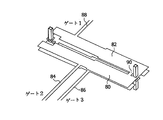
図1に示した共振器は、互いに対向する2つの導電トラック・セクション10、12を含む。それらがオーバーラップする領域において、実際の設計では薄い誘電体層が配置されるが、これは図1には示されていない。比誘電率が大きくなるほど、共振器を小さく作ることができる。したがって、比誘電率εは5よりも大きいことが好ましい。実際の実施形態でも、比誘電率がε>17の材料または比誘電率がε>70の材料でさえ含まれる。誘電体層の厚さdは、導電トラック構成要素10または12の幅bの半分よりも小さい。導電トラック構成要素12の始点16は接地に接続され、導電トラック構成要素10の終点18もアースに接続されている。
The resonator shown in FIG. 1 includes two
図2には、本発明のさらなる実施形態による共振器が示してある。ここで、導電トラック構造20、22はらせん状に設計され、その始点24と終点26とは結合構成要素28を介して互いにリンクし、その結果、それらは同じ浮遊電位にある。
FIG. 2 shows a resonator according to a further embodiment of the invention. Here, the
図1による実施形態と図2による実施形態とを用いて、4分の1波長よりも大幅に小さく、インダクタンスとキャパシタンスとが中で空間的に分離されていない共振器を多層基板で実現することができる。 Using the embodiment according to FIG. 1 and the embodiment according to FIG. 2 to realize a resonator with a multilayer substrate that is significantly smaller than a quarter wavelength and in which the inductance and the capacitance are not spatially separated. Can do.
図3aおよび図3bには、図1または図2による共振器のための多層構造の例が示してある。この場合も、各誘電体層は個々の各層間で省略されている。同様のまたは別の共振器タイプを層状構造で組み合わせることができる。 3a and 3b show examples of multilayer structures for the resonator according to FIG. 1 or FIG. Again, each dielectric layer is omitted between each individual layer. Similar or different resonator types can be combined in a layered structure.
図4には、図1による2つの共振器40、42から作られた帯域通過フィルタが示してある。共振器40、42は、それらの電気的に遠い終点を用いてアース44に取り付けられている。結合コンデンサ46は、フィルタの共振周波数をさらに低減し、平行に走る導電トラック構成要素41を介する誘導性結合とともに、伝送関数に追加のゼロ・ポイントをもたらす。信号の入力または出力は、接続構成要素48、50を介して生じ、直接導電トラック構造に接続される。図4にも、層状構造の一実施例が示してある。フィルタの誘電体層52は25μmの厚さがあり、比誘電率εが18の材料を含む。フィルタを囲む誘電体層54は各々厚さが100μmであり、比誘電率が7.5の材料を含む。接地表面56は、完全な対称構造である。
FIG. 4 shows a bandpass filter made from two
図5には、図4のフィルタの伝送特性S21が示してある。阻止帯は2GHzより下にあり、5GHz領域で良好な伝送特性が達成される。実際には、フィルタの寸法は、ほぼ1×1mm2である。 FIG. 5 shows the transmission characteristic S 21 of the filter of FIG. The stop band is below 2 GHz, and good transmission characteristics are achieved in the 5 GHz region. In practice, the size of the filter is approximately 1 × 1 mm 2 .
図6には、図1による共振器から作られた平衡トランスが示してある。差分信号の入力は、導電トラック構造60のコネクタ64または導電トラック構造62のコネクタ66によって対称に生じる。出力は、導電トラック構造60上のコネクタ68を介して非対称に生じる。導電トラック構造60または62の終点72と74とは、アース70に接続されている。基板の層順序は図4の通りである。分かりやすくするために、図面は垂直方向に延ばしてある。
FIG. 6 shows a balanced transformer made from the resonator according to FIG. The input of the differential signal occurs symmetrically by the
フィルタが平衡トランスおよびアダプタ回路網として同時に使用される場合、特に省スペースになる。図7には、図2に示した原理によって設計された2つの共振器80と82とを有する、組み合わされたフィルタ回路網と平衡回路網とアダプタ回路網との一実施例が示してある。第1の共振器80との結合は、コネクタ84、86を介して対称になる。出力は、接続構成要素88を介して非対称に生じる。対称な接続構成要素84、86と非対称な接続構成要素88とのインピーダンスは、各共振器80または82上のタップの位置を適切に選択することによって改善することができる。図8に示したスペクトラムよりも大きい阻止帯減衰またはより急峻なカーブ(flank)が望まれる場合、さらなる共振器を接続することができる。図12aとともにより詳細に記述されているように、共振器80、82の結合は、接続ブリッジ90を介して付随的に増幅される。
This is especially space-saving when the filter is used simultaneously as a balanced transformer and adapter network. FIG. 7 shows one embodiment of a combined filter network, balanced network and adapter network having two
製造次第では、導電トラック構造の金属層は、上下の位置合わせが完全になされないため、各導電トラックの分布容量と分布インダクタンスとのばらつきが予想される。図9aには、2つの導電トラックが厚さdの誘電体層の上下にオフセットνをもつように構成される、補償されていない構造が示してある。共振周波数におけるこの望ましくないオフセットνの影響は、図9bに示すように、幅2kの導電トラックを用いて補償することができ、kは最大位置オフセットνに誘電体層の層厚dの半分を加えたものにほぼ等しくなるように選ばれる。図10には、図4に示したd=25μmの層シーケンスについての、2つのb=450μm幅の導電トラックを有する構成での位置オフセットの影響が示してある。破線の曲線は、図9aによるk=0μmの補償されていない構造に対する結果であり、実線の曲線は、図9bによるk=50μmの補償された構造に対する結果である。 Depending on the manufacture, the metal layer of the conductive track structure is not perfectly aligned in the vertical direction, so that variation in the distributed capacity and distributed inductance of each conductive track is expected. FIG. 9a shows an uncompensated structure in which the two conductive tracks are configured with an offset ν above and below the dielectric layer of thickness d. The effect of this undesired offset ν on the resonant frequency can be compensated for using a 2k wide conductive track, as shown in FIG. It is chosen to be approximately equal to the addition. FIG. 10 shows the effect of the position offset in the configuration with two b = 450 μm wide conductive tracks for the d = 25 μm layer sequence shown in FIG. The dashed curve is the result for the uncompensated structure of k = 0 μm according to FIG. 9a, and the solid curve is the result for the compensated structure of k = 50 μm according to FIG. 9b.
多層のコイルに似た導電トラックについては、図9bによる補償と比較してより省スペースの方式で設計することができるため、図11による構成には利点がある。重要なことが低い周波数での正確なインダクタンスだけである場合、kに対する前述の近似を使用することができる。共振周波数の正確な調整に対しては、最大の層オフセットνのサイズでの補償値kが適している。アース表面を各導電トラックに近づける場合、補償値をνよりも小さくなるように選ぶことさえできる。図11において、製造ばらつきのために、より低い2つの導電トラックがνの値だけ右側にオフセットされる。補償するために、上層において、隣接する導電トラックがkの量だけさらに離される。図11の左側の導電トラック対において、分布容量と分布インダクタンスとが低減されるが、逆の条件が右側の導電トラック対に適用され、その結果共振周波数は全体として一定のままである。提案された共振器も、各導電トラックの幅のばらつきにそれほど敏感ではない。導電トラック幅が増大する場合、キャパシタンスも増大するが、インダクタンスを減少させることによって部分的にこの影響を補償する。導電トラックの幅とアース表面から離れる距離との比が高いほど、共振周波数の変化は少なくなる。 The configuration according to FIG. 11 is advantageous because a conductive track similar to a multilayer coil can be designed in a more space-saving manner compared to the compensation according to FIG. 9b. If the only important thing is accurate inductance at low frequencies, the above approximation for k can be used. For accurate adjustment of the resonance frequency, the compensation value k at the size of the maximum layer offset ν is suitable. If the ground surface is close to each conductive track, the compensation value can even be chosen to be less than ν. In FIG. 11, due to manufacturing variations, the two lower conductive tracks are offset to the right by the value of ν. To compensate, in the upper layer, adjacent conductive tracks are further separated by an amount k. In the left conductive track pair of FIG. 11, the distributed capacitance and distributed inductance are reduced, but the opposite condition is applied to the right conductive track pair so that the resonant frequency remains constant as a whole. The proposed resonator is also less sensitive to variations in the width of each conductive track. As the conductive track width increases, the capacitance also increases, but partially compensates for this effect by reducing the inductance. The higher the ratio between the width of the conductive track and the distance away from the ground surface, the less the resonant frequency changes.
図12aおよび図12bには、各導電トラック構造間の結合をどのように強化することができるかについての簡略な手段が示してある。図12aのブリッジ90と図12bの共通の導電トラック構成要素92とは、導電トラック構成要素93と94との間または95と96との間の増幅された磁気結合のように振る舞う。回路の残りの部分を大きく変更する必要なしに、ブリッジの位置を変えることによって、結合強度の調整を簡単に行うことができる。したがって、同一の結合が与えられている場合、図12aまたは図12bによる各導体はより大きく分離し、またはより短くなることがある。分離が小さい場合、従来技術によって、結合は製造時の精度に非常に強く依存するが、ブリッジの位置を非常に正確に指定することができる。コイル以上のものとは考えられない、より長い導電トラック構造の場合も、ブリッジ90または共通の導電トラック構成要素92が脚部に近い場合、磁気結合が増大させられる。これは、特に、広帯域の用途または薄型基板上の用途にとって意味がある。
12a and 12b show a simple means as to how the coupling between each conductive track structure can be strengthened. The
図13に示した帯域通過フィルタは、図11に従ってオフセットに対して補償されその終点でアース115に接続されている、図2による2つの共振器110、112によって形成される。導電トラック構成要素114は、平行に配置された導電トラック113の間の磁気結合を増幅する。さらに、コンデンサ118は各共振器を結合する。信号供給ライン122、124の各共振器への結合は、容量性で116によって、かつ直接行われる。導体構造120はアースにリンクした終点コンデンサを形成し、このコンデンサが共振周波数を下げる。
The bandpass filter shown in FIG. 13 is formed by two
Claims (29)
Applications Claiming Priority (2)
| Application Number | Priority Date | Filing Date | Title |
|---|---|---|---|
| EP03102323 | 2003-07-28 | ||
| PCT/IB2004/051228 WO2005011046A1 (en) | 2003-07-28 | 2004-07-15 | High frequency component |
Publications (1)
| Publication Number | Publication Date |
|---|---|
| JP2007500465A true JP2007500465A (en) | 2007-01-11 |
Family
ID=34089704
Family Applications (1)
| Application Number | Title | Priority Date | Filing Date |
|---|---|---|---|
| JP2006521714A Pending JP2007500465A (en) | 2003-07-28 | 2004-07-15 | High frequency components |
Country Status (6)
| Country | Link |
|---|---|
| US (1) | US7592884B2 (en) |
| EP (1) | EP1652264A1 (en) |
| JP (1) | JP2007500465A (en) |
| KR (1) | KR20060057592A (en) |
| CN (1) | CN1830116B (en) |
| WO (1) | WO2005011046A1 (en) |
Cited By (1)
| Publication number | Priority date | Publication date | Assignee | Title |
|---|---|---|---|---|
| JP2010200309A (en) * | 2009-01-30 | 2010-09-09 | Tdk Corp | Proximity antenna and wireless communication device |
Families Citing this family (14)
| Publication number | Priority date | Publication date | Assignee | Title |
|---|---|---|---|---|
| JP4707056B2 (en) * | 2005-08-31 | 2011-06-22 | 富士通株式会社 | Integrated electronic component and integrated electronic component manufacturing method |
| JP4195036B2 (en) * | 2006-01-26 | 2008-12-10 | Tdk株式会社 | Multilayer resonator |
| US20080089324A1 (en) * | 2006-10-13 | 2008-04-17 | Cisco Technology, Inc | Indicating or remarking of a dscp for rtp of a flow (call) to and from a server |
| KR100905873B1 (en) | 2008-01-23 | 2009-07-03 | 삼성전기주식회사 | Wireless communication module |
| JPWO2011148819A1 (en) * | 2010-05-28 | 2013-07-25 | 日本碍子株式会社 | Impedance matching element |
| CN105144319B (en) * | 2013-04-18 | 2017-10-31 | 松下知识产权经营株式会社 | Resonance coupler |
| CN103531878B (en) * | 2013-10-14 | 2015-04-08 | 东南大学 | Push-push and push-pull dual-output substrate integrated waveguide oscillator |
| US10401611B2 (en) | 2015-04-27 | 2019-09-03 | Endochoice, Inc. | Endoscope with integrated measurement of distance to objects of interest |
| CN108963400B (en) * | 2018-06-07 | 2020-04-07 | 中国电子科技集团公司第五十五研究所 | H-shaped mushroom-shaped ultra-wideband common mode noise suppression circuit |
| CN116034631A (en) * | 2020-08-04 | 2023-04-28 | 肖特股份有限公司 | High-frequency feeder and electronic component having the same |
| CN112787061B (en) | 2020-12-31 | 2024-11-19 | 京信通信技术(广州)有限公司 | Coupling structures, resonant structures, low-frequency radiating units, antennas and electromagnetic boundaries |
| JP7651416B2 (en) * | 2021-09-01 | 2025-03-26 | Tdk株式会社 | Antenna Module |
| CN114122659B (en) * | 2021-12-06 | 2022-06-14 | 北京晟德微集成电路科技有限公司 | Microstrip line balun and frequency adjusting method thereof |
| DE102022205469A1 (en) | 2022-05-31 | 2023-11-30 | Q.ant GmbH | Microwave coupler and sensor with a microwave coupler |
Citations (5)
| Publication number | Priority date | Publication date | Assignee | Title |
|---|---|---|---|---|
| JPH07312503A (en) * | 1993-08-24 | 1995-11-28 | Matsushita Electric Ind Co Ltd | Multilayer dielectric antenna duplexer and dielectric filter |
| JPH09139476A (en) * | 1995-11-14 | 1997-05-27 | Sony Corp | Ceramic electrode for ferroelectric capacitor |
| US5640699A (en) * | 1995-01-03 | 1997-06-17 | Rf Prime | Mixer constructed from thick film balanced line structure |
| JP2000516787A (en) * | 1996-09-17 | 2000-12-12 | アールエフ プライム コーポレイション | Thick film components for orthogonal transformation of RF signals |
| JP2002280526A (en) * | 2000-12-26 | 2002-09-27 | Matsushita Electric Ind Co Ltd | Magnetoresistance storage element |
Family Cites Families (8)
| Publication number | Priority date | Publication date | Assignee | Title |
|---|---|---|---|---|
| US5406235A (en) * | 1990-12-26 | 1995-04-11 | Tdk Corporation | High frequency device |
| CN1198258A (en) * | 1996-06-07 | 1998-11-04 | 菲利浦电子有限公司 | Receivers using stripline filters and stripline filters |
| US5697088A (en) | 1996-08-05 | 1997-12-09 | Motorola, Inc. | Balun transformer |
| EP0893839B1 (en) | 1997-01-07 | 2007-08-15 | Matsushita Electric Industrial Co., Ltd. | Multilayer filter |
| US6998939B2 (en) * | 2000-03-08 | 2006-02-14 | Matsushita Electric Industrial Co., Ltd. | Noise filter and electronic device using noise filter |
| SE0004794L (en) | 2000-12-22 | 2002-06-23 | Ericsson Telefon Ab L M | A multilayer symmetry transformer structure |
| DE10123369A1 (en) | 2001-05-14 | 2002-12-05 | Infineon Technologies Ag | Filter arrangement for, symmetrical and asymmetrical pipe systems |
| KR20040001294A (en) * | 2002-06-27 | 2004-01-07 | (주) 래트론 | Distributed constant type filter |
-
2004
- 2004-07-15 JP JP2006521714A patent/JP2007500465A/en active Pending
- 2004-07-15 CN CN2004800220542A patent/CN1830116B/en not_active Expired - Fee Related
- 2004-07-15 EP EP04744587A patent/EP1652264A1/en not_active Withdrawn
- 2004-07-15 WO PCT/IB2004/051228 patent/WO2005011046A1/en not_active Ceased
- 2004-07-15 KR KR1020067002184A patent/KR20060057592A/en not_active Ceased
- 2004-07-15 US US10/565,934 patent/US7592884B2/en not_active Expired - Lifetime
Patent Citations (5)
| Publication number | Priority date | Publication date | Assignee | Title |
|---|---|---|---|---|
| JPH07312503A (en) * | 1993-08-24 | 1995-11-28 | Matsushita Electric Ind Co Ltd | Multilayer dielectric antenna duplexer and dielectric filter |
| US5640699A (en) * | 1995-01-03 | 1997-06-17 | Rf Prime | Mixer constructed from thick film balanced line structure |
| JPH09139476A (en) * | 1995-11-14 | 1997-05-27 | Sony Corp | Ceramic electrode for ferroelectric capacitor |
| JP2000516787A (en) * | 1996-09-17 | 2000-12-12 | アールエフ プライム コーポレイション | Thick film components for orthogonal transformation of RF signals |
| JP2002280526A (en) * | 2000-12-26 | 2002-09-27 | Matsushita Electric Ind Co Ltd | Magnetoresistance storage element |
Cited By (1)
| Publication number | Priority date | Publication date | Assignee | Title |
|---|---|---|---|---|
| JP2010200309A (en) * | 2009-01-30 | 2010-09-09 | Tdk Corp | Proximity antenna and wireless communication device |
Also Published As
| Publication number | Publication date |
|---|---|
| CN1830116B (en) | 2011-04-13 |
| KR20060057592A (en) | 2006-05-26 |
| WO2005011046A1 (en) | 2005-02-03 |
| EP1652264A1 (en) | 2006-05-03 |
| US7592884B2 (en) | 2009-09-22 |
| US20080048797A1 (en) | 2008-02-28 |
| CN1830116A (en) | 2006-09-06 |
Similar Documents
| Publication | Publication Date | Title |
|---|---|---|
| US9077061B2 (en) | Directional coupler | |
| US6828881B2 (en) | Stacked dielectric filter | |
| US7755447B2 (en) | Multilayer balun, hybrid integrated circuit module, and multilayer substrate | |
| US7432786B2 (en) | High frequency filter | |
| US7116185B2 (en) | Balun | |
| JP4579198B2 (en) | Multilayer bandpass filter | |
| KR100981524B1 (en) | Couplers, integrated electronics and electronic devices and methods of using the same | |
| US7777589B2 (en) | Balun transformer | |
| US7183872B2 (en) | Laminated balun transformer | |
| JP2007500465A (en) | High frequency components | |
| US7068122B2 (en) | Miniaturized multi-layer balun | |
| US9331658B2 (en) | Filter circuit | |
| US12244287B2 (en) | Filter device and multiplexer | |
| JP3390344B2 (en) | Laminated dielectric filter and high frequency circuit board | |
| WO2004091036A1 (en) | Passive component | |
| US12347917B2 (en) | Directional coupler | |
| US8018305B2 (en) | Electronic component | |
| US8878634B2 (en) | Bandpass filter, and wireless communication module and wireless communication device using the bandpass filter | |
| US7463120B2 (en) | High frequency filter | |
| JP2005244848A (en) | Balun filter | |
| JPH1197962A (en) | High-frequency component | |
| US7548141B2 (en) | High frequency filter | |
| JP2008061082A (en) | Balance filter circuit and high frequency device using the same | |
| JP2009171211A (en) | Layered balun, hybrid integrated circuit module, and multilayer substrate |
Legal Events
| Date | Code | Title | Description |
|---|---|---|---|
| A621 | Written request for application examination |
Free format text: JAPANESE INTERMEDIATE CODE: A621 Effective date: 20070713 |
|
| A711 | Notification of change in applicant |
Free format text: JAPANESE INTERMEDIATE CODE: A711 Effective date: 20080529 |
|
| A977 | Report on retrieval |
Free format text: JAPANESE INTERMEDIATE CODE: A971007 Effective date: 20100616 |
|
| A131 | Notification of reasons for refusal |
Free format text: JAPANESE INTERMEDIATE CODE: A131 Effective date: 20100625 |
|
| A02 | Decision of refusal |
Free format text: JAPANESE INTERMEDIATE CODE: A02 Effective date: 20101203 |