JP2007336277A - Moving image encoding and decoding method, encoding and decoding device and moving image encoding and decoding program - Google Patents
Moving image encoding and decoding method, encoding and decoding device and moving image encoding and decoding program Download PDFInfo
- Publication number
- JP2007336277A JP2007336277A JP2006166074A JP2006166074A JP2007336277A JP 2007336277 A JP2007336277 A JP 2007336277A JP 2006166074 A JP2006166074 A JP 2006166074A JP 2006166074 A JP2006166074 A JP 2006166074A JP 2007336277 A JP2007336277 A JP 2007336277A
- Authority
- JP
- Japan
- Prior art keywords
- moving image
- motion vector
- decoding
- subframe
- image signal
- Prior art date
- Legal status (The legal status is an assumption and is not a legal conclusion. Google has not performed a legal analysis and makes no representation as to the accuracy of the status listed.)
- Pending
Links
Images


Landscapes
- Compression Or Coding Systems Of Tv Signals (AREA)
Abstract
Description
本発明は、動画像信号の符号化復号化技術に関する。 The present invention relates to a coding / decoding technique for a moving image signal.
近年、圧縮技術の向上により、高い圧縮率による動画像信号の符号化が可能になってきている。例えば、TV電話等を目的とした規格H.261や、放送、ストレージメディアを目的とした規格MPEG(Motion Picture Expert Group)等が制定されている。これらの規格に準拠した動画像信号符号化方式は、動き補償フレーム間予測符号化方式と、離散コサイン変換(Discrete Cosine transformation; DCT)とを中核としている。このため、動画像信号符号化処理は、所要処理量が多い。 In recent years, with the improvement of compression technology, it has become possible to encode a moving image signal at a high compression rate. For example, the standard H.264 for videophones and the like. 261 and standards such as MPEG (Motion Picture Expert Group) for broadcasting and storage media have been established. A moving image signal encoding method compliant with these standards has a motion compensation interframe predictive encoding method and a discrete cosine transformation (DCT) as the core. For this reason, the moving image signal encoding process requires a large amount of processing.
動画像信号復号化処理に要する処理量は、符号化処理に要する処理量に比較すれば少ない。しかしながら、この復号化処理は、低処理速度のプロセッサを搭載した携帯端末には、大きな負担となる。 The processing amount required for the moving image signal decoding process is small as compared with the processing amount required for the encoding process. However, this decryption processing is a heavy burden for a portable terminal equipped with a low processing speed processor.
図1及び図2を参照して、従来の動画像符号化技術につき説明する。なお、この技術については、特開平9−037269(特許文献1)、特開平6−268996(特許文献2)等で説明されている。 With reference to FIG. 1 and FIG. 2, a conventional moving picture coding technique will be described. This technique is described in JP-A-9-037269 (Patent Document 1), JP-A-6-268996 (Patent Document 2), and the like.
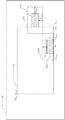
図1は、従来の動画像信号符号化装置の構成例を示すブロック図であり、図2は、従来の動画像信号復号化装置の構成例を示すブロック図である。 FIG. 1 is a block diagram illustrating a configuration example of a conventional moving image signal encoding device, and FIG. 2 is a block diagram illustrating a configuration example of a conventional moving image signal decoding device.
図1に示されたとおり、従来の動画像信号符号化装置は、動き検出部2と符号化部30とからなる。符号化部は、減算器31と、変換部32と、逆変換部33と、加算器34と、動き補償部35とからなる。
As shown in FIG. 1, the conventional moving image signal encoding apparatus includes a motion detection unit 2 and an encoding unit 30. The encoding unit includes a
図2に示されるとおり、従来の動画像信号復号化装置は、復号化部40を含む。復号化部は、逆変換部41と、加算器42と、動き補償部43とからなる。
As shown in FIG. 2, the conventional moving image signal decoding apparatus includes a
次に、図1及び図2の動作を説明する。 Next, the operation of FIGS. 1 and 2 will be described.
なお、動画像信号の最初のフレームは、そのまま変換部32に直接供給されてフレーム内符号化され、また逆変換部33出力がそのまま局部復号信号39となることは、周知の通りである。以下では、動画像信号の第2フレーム以降の処理のみを説明する。
As is well known, the first frame of the moving image signal is directly supplied to the
図1において、入力動画像信号1は、動き検出部2及び減算器31に供給される。動き検出部2は、入力動画像信号1と加算器34からの局部復号信号39とから、入力動画像信号のブロック毎に、動きベクトルvx、yを検出する。なお、この動き検出部2の構成、動作については、前述の特許文献1及び特許文献2に記載されているので、詳細な説明は、省略する。
In FIG. 1, an input
減算器31の第1の入力へは、入力号画像信号1が供給される。減算器31の第2の入力へは、動き補償部35から、動き補償フレーム間予測信号が供給される。減算器31は、入力動画像信号から動き補償フレーム間予測信号を減算し、差分信号を変換部32に供給する。
The input
変換部32は、この差分信号に、DCT変換及び量子化を施し、予測誤差信号Eを出力する。
The
逆変換部33は、この予測誤差信号Eに逆量子化及び逆DCT変換を施し、逆変換結果を加算器34に供給する。加算器34の他の入力には、動き補償部35から動き補償フレーム間予測信号が供給されている。加算器34は、逆変換器33出力と動き補償フレーム間予測信号とを加算し、局部復号信号39を生成する。この局部復号信号39は、減算器31及び動き検出部2に供給される。
The
また、この局部復号信号39は、動き補償部35にも供給される。動き補償部35は、少なくとも1フレームの容量を有するメモリを内蔵しており、局部復号信号39及び動きベクトルvx,yとに基づいて、動き補償フレーム間予測信号を生成する。
The local decoded
このようにして生成された予測誤差信号E及び動きベクトルvx,yは多重化され、符号化動画像データとして、伝送されあるいはストレージメディアに格納される。 The prediction error signal E and the motion vector v x, y generated in this way are multiplexed and transmitted as encoded moving image data or stored in a storage medium.
次に、図2の動画像信号復号化装置の動作につき説明する。 Next, the operation of the moving picture signal decoding apparatus in FIG. 2 will be described.
図2において、予測誤差信号Eは、逆変換部41に供給され、動きベクトルvx,yは、動き補償部43に供給される。逆変換部41の動作は、図1の逆変換部33と同一であり、逆変換部41出力は加算器42に供給される。
In FIG. 2, the prediction error signal E is supplied to the inverse transform unit 41, and the motion vector v x, y is supplied to the
加算器42の他の入力へは、動き補償部43から、動き補償フレーム間予測信号が供給される。加算器42は、逆変換部41出力と動き補償フレーム間予測信号とを加算し、復号動画像信号44を出力する。
The motion compensation inter-frame prediction signal is supplied from the
この復号動画像信号44は、動き補償部43にも供給される。動き補償部43の構成及び機能は、図1の動き補償部35と同一である。動き補償部43は、復号動画像信号44及び動きベクトルvx,yとに基づいて、動き補償フレーム間予測信号を生成する。
The decoded
前述したとおり、符号化技術の進展に伴い、動画像信号化の符号化及び符号化された動画像信号の復号化に必要となる処理量は、増加してきている。このため、これらの処理を行う電子機器は、高い処理能力が要求される。 As described above, with the progress of encoding technology, the amount of processing required for encoding of moving image signal and decoding of the encoded moving image signal has increased. For this reason, an electronic device that performs these processes is required to have a high processing capacity.
しかしながら、この要求は、常に満足されるとは限らない。高い処理能力を持つ装置で動画像信号を符号化し、この符号化データを、他の低い処理能力しか持たない装置で復号化するケースも避けることはできない。 However, this requirement is not always satisfied. A case where a moving image signal is encoded by a device having a high processing capability and this encoded data is decoded by another device having only a low processing capability cannot be avoided.
その一例は、符号化された動画像信号を格納したサイトから、符号化動画像データをダウンロードし、携帯電話等の低処理速度の機器により、この動画像信号を視聴する場合である。この例では、符号化動画像データを復号する処理が、通信回線から供給される符号化動画像データの供給速度に追随できなくなり、この符号化動画像データをリアルタイムで復号することが困難となることがある。 One example thereof is a case where encoded moving image data is downloaded from a site that stores the encoded moving image signal, and this moving image signal is viewed by a low processing speed device such as a mobile phone. In this example, the process of decoding the encoded moving image data cannot follow the supply speed of the encoded moving image data supplied from the communication line, and it becomes difficult to decode the encoded moving image data in real time. Sometimes.
また、他の例としては、次のケースも考えられる。携帯端末では、バッテリの枯渇を防止するため、バッテリの残存容量が少なくなってくると、プロセッサの動作速度を下げることがある。この場合には、バッテリの残存容量が充分にある場合には、正常に復号可能な符号化動画像データであっても、バッテリの残存容量が少なくなっているときには、正常な復号動作が行えなくなる。また、バッテリの残存容量が充分には残されていない場合には、符号化動画像データの復号を禁止する機器もある。 As another example, the following case can be considered. In the portable terminal, in order to prevent the battery from being depleted, the operating speed of the processor may be lowered when the remaining capacity of the battery decreases. In this case, if the remaining capacity of the battery is sufficient, even if it is encoded moving image data that can be normally decoded, if the remaining capacity of the battery is low, a normal decoding operation cannot be performed. . In addition, there is a device that prohibits decoding of encoded moving image data when the remaining capacity of the battery is not sufficient.
また、高い処理能力を持つ機器においても、複数の符号化動画像データを並列に復号する場合には、個々の符号化動画像データに配分される処理能力は小さくなるため、同様の課題が発生し得る。 In addition, even in a device having high processing capability, when decoding a plurality of encoded moving image data in parallel, the processing capability allocated to each encoded moving image data becomes small, and the same problem occurs. Can do.
これらの課題に対応するための一つのアプローチとして、1フレーム中の全ての符号化データを復号せずに、全フレームの一部であるサブフレーム(例えば、動画像のフレームの中央部)のみを復号することが考えられる。被写体にも依存するが、一般には、フレームの中央に近い領域ほど視聴者にとって有益な情報を含むことが多いからである。例えば、特開2001−8040(特許文献3)は、符号化された静止画像データの一部を取り出して、静止画像の一部のみを復号する技術を開示している。 One approach to addressing these issues is to decode only the subframes that are part of all frames (for example, the central part of a moving image frame) without decoding all the encoded data in one frame. Decoding is conceivable. Although it depends on the subject, generally, the region closer to the center of the frame often contains information useful to the viewer. For example, Japanese Patent Laid-Open No. 2001-8040 (Patent Document 3) discloses a technique of extracting a part of encoded still image data and decoding only a part of the still image.
しかしながら、MPEGに代表される動画像符号化技術では、動き補償フレーム間予測符号化を中核としているため、この特許文献3記載の技術をそのまま用いることはできない。この理由を、次に、説明する。 However, in the moving picture encoding technique represented by MPEG, the technique described in Patent Document 3 cannot be used as it is because motion compensation interframe predictive encoding is the core. The reason for this will now be described.
既に述べたとおり、動き補償フレーム間予測符号化は、動画像データの符号/復号対象フレーム(カレントフレーム)を符号化/復号化する際に、カレントフレームと過去のフレーム(参照フレーム)との差分を利用する技術である。 As already described, motion compensation inter-frame predictive encoding is the difference between the current frame and the past frame (reference frame) when encoding / decoding the encoding / decoding target frame (current frame) of moving image data. Is a technology that uses
図3は、動き補償フレーム間予測符号化の概念を説明するための図である。 FIG. 3 is a diagram for explaining the concept of motion compensation interframe predictive coding.
動画像信号のフレーム101は、複数のブロックに分割され、ブロック毎に、動きベクトルが求められる。ここで、カレントフレーム内のブロック103に注目する。このブロック103の動きベクトルは、次のようにして求められる。図1の動き検出部2は、このブロック103内の画像データと、参照フレーム内の動きベクトル探索範囲104内の画像データとの類似度を種々の候補ベクトルにつき求める。そして、動き検出部は、この類似度を最大とする候補ベクトルを、前述した動きベクトルとして出力する。
A
ここで、動画像信号のフレーム101内に、サブフレーム102を設定し、符号化動画像データから、サブフレーム内に属する符号化データのみを取り出して、サブフレーム102の動画像信号のみを復号することを考えてみる。この場合、サブフレーム内のブロック103に対する動き補償フレーム間符号化予測信号が、サブフレーム外の参照フレームから作成されることが、起こりうる。前述したとおり、動き補償フレーム間予測符号化により生成された符号化動画像データを復号するためには、参照フレーム内の探索領域の再生動画像信号が不可欠である。しかしながら、この場合には、復号化装置は、サブフレーム102外の再生動画像信号を得ることは必ずしもできない。つまり、カレントフレームのサブフレーム内の全てのブロックについて、参照フレーム内の再生動画像信号が常に得られる保証はない。したがって、特許文献3記載の技術を、動き補償フレーム間予測符号化にそのまま適用することはできない。
Here, the subframe 102 is set in the
フレーム101内の符号化動画像データを全て復号して再生動画像信号を得、この再生動画像信号からサブフレームを抜き出すことはもちろん可能である。しかしながら、このような形態は、表示する動画像のサイスを小さくしても、所要演算量を減少させることはできない。
Of course, it is possible to decode all the encoded moving image data in the
本発明は、符号化動画像データの一部を抜き出して復号可能な動き補償フレーム間予測符号化復号化後術を提供する。 The present invention provides a motion compensated inter-frame predictive coding / decoding post-operation that can extract and decode a part of coded moving image data.
本発明の第1の側面は、入力動画像信号の動きベクトルを検出し、この動きベクトルを基に前記入力動画像信号を符号化し、予測誤差信号と前記動きベクトルを多重化して符号化データを出力する動画像信号符号化方法であり、この入力動画像信号は、各フレーム内に領域情報により指定されるサブフレームが設定された入力動画像信号であり、このサブフレーム内のカレントフレームのブロックの動きベクトル検出の際には、この動きベクトルの探索範囲を、参照フレーム内のサブフレーム内に制限することを特徴とする動画像信号符号化方法を提供する。 In a first aspect of the present invention, a motion vector of an input video signal is detected, the input video signal is encoded based on the motion vector, and a prediction error signal and the motion vector are multiplexed to generate encoded data. This is a moving image signal encoding method to be output. This input moving image signal is an input moving image signal in which a subframe specified by region information is set in each frame, and a block of a current frame in this subframe. When the motion vector is detected, a motion picture signal encoding method is provided in which the search range of the motion vector is limited to a subframe in a reference frame.
また、本発明の第2の側面は、たとえば、この第1の側面により生成された符号化データを、復号するための復号化方法を提供する。この第2の側面により提供される復号化方法は、前記領域情報に基づいて、前記符号化データから前記サブフレーム内の符号化データを抜き出す抜き出しステップと、抜き出された符号化データを復号化するステップと備えたことを特徴とする。 Moreover, the 2nd side surface of this invention provides the decoding method for decoding the encoding data produced | generated by this 1st side surface, for example. The decoding method provided by the second aspect includes an extraction step of extracting encoded data in the subframe from the encoded data based on the region information, and decoding the extracted encoded data And a step of performing.
本発明のさらに他の側面については、発明を実施するための最良の形態の記載から明らかになるであろう。 Further aspects of the present invention will become apparent from the description of the best mode for carrying out the invention.
本発明によれば、低処理速度のプロセッサを搭載した機器によっても、動き補償フレーム間予測符号化された動画像信号を復号可能である。 According to the present invention, it is possible to decode a moving image signal that has undergone motion compensation interframe predictive coding even by a device equipped with a processor having a low processing speed.
本発明では、サブフレーム内のブロックについては、参照フレームのサブフレーム外の領域を、動きベクトル探索範囲から除外している。このため、サブフレーム内の動画像信号を復号するためには、サブフレーム外の再生動画像信号は不要となる。したがって、復号化側の装置は、サブフレーム内のブロックの符号化データのみを復号すれば、サブフレーム内の動画像信号を再生できる。このため、処理速度の小さいプロセッサを搭載した機器であっても、動き補償フレーム間符号化された動画像信号から、サブフレーム内の符号化データのみをとりだして、サブフレームの動画像信号のみを復号再生することができる。 In the present invention, for a block in a subframe, an area outside the subframe of the reference frame is excluded from the motion vector search range. For this reason, in order to decode the moving image signal in a sub-frame, the reproduction | regeneration moving image signal outside a sub-frame becomes unnecessary. Therefore, the decoding apparatus can reproduce the moving image signal in the subframe by decoding only the encoded data of the block in the subframe. For this reason, even a device equipped with a processor with a low processing speed can extract only the encoded data in the subframe from the video signal encoded by motion compensation interframe, and only the video signal in the subframe can be extracted. Decoding and playback can be performed.
次に図面を参照して、本発明を実施するための最良の形態につき説明する。 Next, the best mode for carrying out the present invention will be described with reference to the drawings.
図4は、本発明の一実施形態に係る動き補償フレーム間予測符号化装置の構成例を示すブロック図である。図5は、本発明の一実施形態に係る動き補償フレーム間復号化装置の構成例を示すブロック図である。図6は、図4の装置の動作を説明するためのフローチャートである。図7は、図4の動き検出部50の動作を説明するための図である。図8は、図5の動き補償フレーム間復号化装置の動作を説明するためのフローチャートである。
FIG. 4 is a block diagram illustrating a configuration example of a motion compensation interframe prediction encoding apparatus according to an embodiment of the present invention. FIG. 5 is a block diagram showing a configuration example of a motion compensation inter-frame decoding apparatus according to an embodiment of the present invention. FIG. 6 is a flowchart for explaining the operation of the apparatus of FIG. FIG. 7 is a diagram for explaining the operation of the
図4の動き補償フレーム間予測符号化装置は、動き検出部50と、符号化部30とからなる、この符号化部30は、図1の符号化部30と同一構成である。
The motion compensated inter-frame prediction encoding apparatus in FIG. 4 includes a
図5の動き補償フレーム間復号化装置は、フィルタ部60と復号化部40とからなる、この復号化部40は、図2の復号化部40と同一構成である。
The motion compensated inter-frame decoding apparatus in FIG. 5 includes a
次に、図6、図7をも参照して、図4の動き補償フレーム間予測符号化装置の動作を説明する。ただし、符号化部30の動作は、既に図1を参照して説明したので、重複した説明は省略し、動き検出部50の動作につき詳細に説明する。
Next, the operation of the motion compensated interframe predictive coding apparatus in FIG. 4 will be described with reference to FIGS. However, since the operation of the encoding unit 30 has already been described with reference to FIG. 1, redundant description will be omitted, and the operation of the
図6に示した処理は、カレントフレームのブロック毎に起動される。
図6のステップS1では、動き検出部50は、動きベクトルの探索対象となる複数個の候補ベクトルux、y)のリストである候補ベクトルリストを、内部に設定する。この候補ベクトルリストは、動き検出部50に内蔵されているマスターリストをコピーすることにより作成することができる。また、この候補ベクトル群の作成法については、多くの周知技術が知られているが、これらの周知技術に基づいて、候補ベクトルリストを作成してもよい。一例を挙げれば、前述の特許文献1は、過去の動きベクトル検出結果の分布に基づいて、候補ベクトルリストを生成することを記載している。
The process shown in FIG. 6 is activated for each block of the current frame.
In step S1 of FIG. 6, the
図7は、本例では、
|ux|≦Uxmax、|uy|≦Uymax
を満たす、候補ベクトルを有する候補ベクトルリストが、生成されることを示している。例えば、図7のブロック105については、この条件を満足する候補ベクトルリストに対応する動くベクトル探索範囲106が、参照フレーム内に設定される。
In this example, FIG.
| U x | ≦ Uxmax, | u y | ≦ Uymax
This indicates that a candidate vector list having candidate vectors that satisfies the above is generated. For example, for the
ステップS2では、動き検出部50は、現ブロックが、サブフレーム内にあるか否かを判定する。例えば、図7のカレントフレームのブロック103は、サブフレーム102内にあると判定され、ブロック105は、サブフレーム外にあると判定される。この判定は、カレントフレームのブロックの左上の座標値(x0、y0)、ブロックサイズ(水平方向M画素、垂直方向N画素)、及び、領域情報((Xmin、Ymin)、(Xmax、Ymax))に基づいて、行われる。
In step S2, the
ステップS2での判定結果がYesの場合、動き検出部の処理は、ステップS3に進み、そうでない場合には、動き検出部の処理は、ステップS4に進む。 If the determination result in Step S2 is Yes, the process of the motion detection unit proceeds to Step S3, and if not, the process of the motion detection unit proceeds to Step S4.
ステップS3では、動き検出部50は、図7に示した例では、次の条件(1)から条件(4)の少なくとも1つを満足する候補ベクトル(ux、uy)を、候補ベクトルリストから削除する。即ち、動くベクトル探索範囲が、サブフレーム外に出てしまう候補ベクトルを、候補ベクトルリストから削除する。
In step S3, in the example illustrated in FIG. 7, the
(1)x0―ux<Xmin
(2)x0+M−ux>Xmax
(3)y0―uy<Ymin
(4)y0+N−uy>Ymax
候補ベクトルリストからこのような削除を行うことにより、動き検出部50は、サブフレーム内のブロックについては、サブフレーム外の参照フレームを探索しなくなる。例えば、図7のブック105の探索範囲は、参照符号104aで示した範囲となる。
(1) x 0 -u x <X min
(2) x 0 + M−u x > X max
(3) y 0 -u y <Y min
(4) y 0 + N−u y > Y max
By performing such deletion from the candidate vector list, the
また、図7は、サブフレーム外のブロック105については、候補ベクトルリストからの削除は行われないことを示している(動きベクトル探索範囲106参照)。
Further, FIG. 7 shows that the
ステップS4では、動き検出部50は、候補ベクトルリストに残されている候補ベクトルについて、カレントフレームのブロックの画像データと、参照フレーム画像データとの類似度計算を行い、そのブロックについての動きベクトルvX、yを、算出する。
In step S4, the
ステップS5では、符号化部30は、ステップS4で求められた動きベクトルを使用して、入力動画像信号を動き補償フレーム間予測符号化し、予測誤差信号Eを生成し、動きベクトルとともに出力する。
なお、本例では、領域情報((Xmin、Ymin)、(Xmax、Ymax))を、予測誤差信号E、動きベクトルvx、yと多重化し、この多重化された情報を符号化動画像データとして伝送あるいはストレージメディアに蓄積されてもよい。この場合の構成例を、図9に示した。この図9の動作については、以上の説明から明らかであるので、説明は省略する。
勿論、この領域情報が動き補償フレーム間予測符号化装置、動き補償フレーム間復号化装置の間で、既知である場合には、このような領域情報の多重化は不要である。
In step S5, the encoding unit 30 uses the motion vector obtained in step S4 to perform the motion compensation interframe predictive encoding on the input moving image signal, generates a prediction error signal E, and outputs it together with the motion vector.
In this example, the region information ((X min , Y min ), (X max , Y max )) is multiplexed with the prediction error signal E and the motion vectors v x, y, and this multiplexed information is encoded. It may be transmitted or stored in storage media as converted video data. A configuration example in this case is shown in FIG. Since the operation of FIG. 9 is clear from the above description, the description is omitted.
Of course, when this region information is already known between the motion compensation inter-frame prediction encoding device and the motion compensation inter-frame decoding device, such multiplexing of region information is not necessary.
次に、図8を参照して、図5の動画像信号復号化装置の動作を説明する。 Next, the operation of the video signal decoding apparatus in FIG. 5 will be described with reference to FIG.
図5の動き補償フレーム間復号化装置は、フィルタ部60と復号化部40とからなる。この復号化部40は、図2の復号化部40と同一構成である。したがって、以下では、フィルタ部60の動作を中心にして説明する。
The motion compensated interframe decoding apparatus in FIG. 5 includes a
なお、ここでは、領域情報が、動き補償フレーム間符号化装置と動き補償フレーム間復号化装置との間で、既知であり、この領域情報は、動き補償フレーム間復号化装置内に設定されているものとして説明する。図8は、動き補償フレーム間予測符号化装置の動作を説明するためのフローチャートである。なお、図5の動き補償フレーム間復号化装置では、図8のステップS22の判定は行われず。ステップS21、ステップS23,ステップS24の処理が、この順序で実行される。ステップS22の処理が必要となる」場合については、後述する。 Here, the region information is already known between the motion compensation interframe coding apparatus and the motion compensation interframe decoding apparatus, and this region information is set in the motion compensation interframe decoding apparatus. Explain that it is. FIG. 8 is a flowchart for explaining the operation of the motion compensation interframe predictive coding apparatus. In the motion compensation inter-frame decoding apparatus in FIG. 5, the determination in step S22 in FIG. 8 is not performed. Steps S21, S23, and S24 are executed in this order. The case where the process of step S22 is necessary ”will be described later.
ステップS21において、フィルタ部60は、動き補償フレーム間予測誤差Eと動きベクトルvx、yとを、ブロック毎に受信する。
In step S21, the
次に、ステップS23では、フィルタ部は、入力された動き補償フレーム間予測誤差信号と動きベクトルが、サブフレーム内のブロックの符号化動画像データであるか否かを、領域情報に基づいて、判定する。フィルタ部60は、ステップS23で,その符号化動画像データがサブフレーム内のブロックに属する場合にのみ、この符号化動画像データを出力する(図5のE’及びv'x、y)。
Next, in step S23, the filter unit determines whether the input motion compensation inter-frame prediction error signal and the motion vector are the encoded moving image data of the block in the subframe based on the region information. judge. The
ステップS24では、復号化部40は、フィルタ部から供給された符号化動画像データを復号する。このようにして、サブフレーム内の動画像信号が再生される。
In step S24, the
このように、図4、図5を参照して説明された実施形態は、動き補償フレーム間予測符号化方式を用いて生成された符号化動画像データの一部を取り出して、動画像信号を復号再生することを可能とする。したがって、本実施形態は、低演算速度のプロセッサを搭載した携帯端末等でも、動画像信号を利用することを可能とする。 As described above, the embodiment described with reference to FIGS. 4 and 5 extracts a part of the encoded moving image data generated by using the motion compensation interframe predictive encoding method, Decoding and reproduction are possible. Therefore, this embodiment makes it possible to use a moving image signal even in a portable terminal or the like equipped with a processor with a low calculation speed.
次に、本発明に係る動画像フレーム間復号化装置の他の例について。図10を参照して説明する。 Next, another example of the moving picture interframe decoding apparatus according to the present invention will be described. This will be described with reference to FIG.
先に、[発明が解決しようとする課題]の欄で述べたとおり、携帯端末等では、バッテリの残存容量が少なくなってくると、プロセッサの処理速度を低下させ、消費電力を低減する機能を備えたものが少なくない。このようば機器では、通常は、フルサイスの符号化動画像データを復号可能な機器であっても、バッテリ残存容量の低下あいた場合には、フルサイスの動画像信号を復号できなくなる。 First, as described in the section “Problems to be Solved by the Invention”, a portable terminal or the like has a function of reducing the processing speed of the processor and reducing power consumption when the remaining capacity of the battery decreases. There are a lot of things to prepare. In such a device, even if a device capable of decoding full-size encoded moving image data is normally used, a full-size moving image signal cannot be decoded if the remaining battery capacity is low.
また、複数のタスクを並列的に実行できる機器では、これら複数のタスクに、プロセッサの処理能力を配分する。このような機器でも、他のタスクが稼動している場合には、符号化動画像データの復号処理に、プロセッサの処理能力を充分には与えることができなくなるので、ユーザは、この他のタスクを終了させるか、あるいは、符号化動画像データの復号処理の実行を断念するかを選択せざるを得なくなる。
図10の動き補償フレーム間復号化装置は、このような場合に、有益である。以下に、説明する。
Further, in a device that can execute a plurality of tasks in parallel, the processing capacity of the processor is allocated to the plurality of tasks. Even in such a device, when other tasks are in operation, the processing capability of the processor cannot be sufficiently given to the decoding processing of the encoded moving image data. Must be terminated or whether to abandon execution of the decoding process of the encoded moving image data.
The motion compensation interframe decoding apparatus of FIG. 10 is useful in such a case. This will be described below.
図10の動き補償フレーム間復号化装置は、フィルタ部61と復号化部40とを備える。図10の復号化部40は、図2及び図5の復号化部40と同一構成である。この例では、領域情報は、復号化装置内に前もって設定されていてもよいし、予測誤差信号E、動きベクトルとともに、ストレージメディア等から供給されていてもよい。
The motion compensation inter-frame decoding apparatus in FIG. 10 includes a
この例では、図8のフローチャート示された処理がそのまま実行される。 In this example, the process shown in the flowchart of FIG. 8 is executed as it is.
ステップS22では、フィルタ部61は、図10の選択情報をチェックし、領域情報を使用した符号化動画像データの抜き出しを行うか否かを決定する。
In step S22, the
この選択情報は、この動き補償フレーム間復号化装置を搭載した電子機器が生成する。即ち、バッテリ残存容量が少なくなってくると、プロセッサの処理速度を低下させる機器は、バッテリバッテリ残存容量が少なくなってきた時点で、この選択情報を生成し、フィルタ部61に供給する。また、タスクの稼働状況に応じて、各タスクにプロセッサの処理能力を割り当てる機器は、稼働状況に応じて、この選択情報を生成し、フィルタ部61に供給する。
This selection information is generated by an electronic device equipped with this motion compensation interframe decoding apparatus. That is, when the remaining battery capacity decreases, a device that reduces the processing speed of the processor generates this selection information and supplies it to the
ステップS22での判定結果が“Yes”の場合、フィルタ部61は、図5のフィルタ部60と同様に、サブフレーム内のブロックの予測誤差信号、動きベクトルのみを復号化部40に供給する。そして、復号化部40は、供給された動き補償フレーム間予測誤差信号及び動きベクトルに基づいて、動画像信号を再生する。
When the determination result in step S22 is “Yes”, the
ステップS22での判定結果が“No”の場合、フィルタ部61は、受信した予測誤差信号及び動きベクトルを、復号化部に供給する。
When the determination result in step S22 is “No”, the
このように、図10の動き補償フレーム間復号化装置は、バッテリの残存容量や、動き補償フレーム間復号化処理に割る当てられるプロセッサの処理能力に応じて、動き補償フレーム間予測符号化により生成された符号化動画像データを、その表示サイズを変更することにより、動画像信号の再生を継続することができる。 As described above, the motion compensation inter-frame decoding apparatus of FIG. 10 is generated by motion compensation inter-frame prediction encoding according to the remaining capacity of the battery and the processing capacity of the processor allocated to the motion compensation inter-frame decoding processing. The reproduction of the moving image signal can be continued by changing the display size of the encoded moving image data.
なお、本発明は、図6、図8に例示したフローチャートに対応するプログラムをロードしたコンピュータによっても実行せきることは、当業者には明らかであろう。 It will be apparent to those skilled in the art that the present invention can also be executed by a computer loaded with a program corresponding to the flowcharts illustrated in FIGS.
動画像信号の符号化技術に適用可能である。 The present invention is applicable to a moving image signal encoding technique.
2、50 動き検出部
30 符号化部
31 減算器
32 変換部
33、41逆変換部
34、42 加算器
35、43 動き補償部
101 フレーム
102 サブフレーム
103、105 ブロック
104、104a、106 動きベクトル探索範囲
2, 50 Motion detection unit 30
Claims (16)
前記サブフレーム内のカレントフレームのブロックの動きベクトル検出の際には、この動きベクトルの探索範囲を、参照フレーム内のサブフレーム内に制限する
ことを特徴とする動画像信号符号化方法。 A moving image signal encoding method that detects a motion vector of an input moving image signal, encodes the input moving image signal based on the motion vector, multiplexes a prediction error signal and the motion vector, and outputs encoded data. The input moving image signal is an input moving image signal in which a subframe specified by region information is set in each frame;
A moving picture signal encoding method characterized by limiting a search range of a motion vector to a subframe in a reference frame when detecting a motion vector of a block of a current frame in the subframe.
前記領域情報に基づいて、前記符号化データから前記サブフレーム内の符号化データを抜き出す抜き出しステップを更に備え、
前記抜き出された符号化データを復号化する
ことを特徴とする動画像信号復号化方法。 A method for decoding encoded data generated by detecting a motion vector of an input moving image signal and encoding the input moving image signal based on the motion vector. When encoding an input video signal in which a subframe specified by region information is set, the motion vector search range of the current frame block in the subframe is limited to the subframe in the reference frame. A video signal decoding method for decoding encoded data generated by
A step of extracting the encoded data in the subframe from the encoded data based on the region information;
A moving picture signal decoding method, wherein the extracted encoded data is decoded.
前記入力動画像信号は、各フレーム内に領域情報により指定されるサブフレームが設定された入力動画像信号であり、
前記動き検出手段は、サブフレーム内のカレントフレームのブロックの動きベクトル検出の際には、この動きベクトルの探索範囲を、参照フレーム内のサブフレーム内に制限する
ことを特徴とする動画像信号符号化装置。 A motion detecting means for detecting a motion vector of the input moving picture signal; and an encoding means for encoding the input moving picture signal based on the motion vector, multiplexing the prediction error signal and the motion vector, and outputting the multiplexed signal. In the moving image signal encoding device,
The input moving image signal is an input moving image signal in which a subframe specified by region information is set in each frame,
The motion detection means, when detecting a motion vector of a block of a current frame in a subframe, restricts a search range of the motion vector to a subframe in a reference frame. Device.
前記領域情報に基づいて、前記符号化データから前記サブフレーム内の符号化データを抜き出す手段と、
前記抜き出された符号化データを復号化する復号化手段、
とを備えたことを特徴とする動画像信号復号化装置。 An apparatus for decoding encoded data generated by a method of detecting a motion vector of an input moving image signal and encoding the input moving image signal based on the motion vector. When encoding an input video signal in which a subframe specified by region information is set, the motion vector search range of the current frame block in the subframe is limited to the subframe in the reference frame. A video signal decoding device for decoding encoded data generated by
Means for extracting encoded data in the subframe from the encoded data based on the region information;
Decoding means for decoding the extracted encoded data;
A video signal decoding device comprising:
入力動画像信号の動きベクトルを検出する動き検出ステップと、
この動きベクトルを基に前記入力動画像信号を符号化し、予測誤差信号と前記動きベクトルを多重化して符号化データを出力する符号化ステップとからなり、
前記動き検出ステップは、前記サブフレーム内のカレントフレームのブロックの動きベクトル検出の際には、この動きベクトルの探索範囲を、参照フレーム内のサブフレーム内に制限する
ことを特徴とする動画像信号符号化プログラム。 A moving image signal encoding program for causing a computer to execute a moving image signal encoding method, wherein the input moving image signal is an input moving image signal in which a subframe specified by region information is set in each frame And the program is
A motion detection step for detecting a motion vector of the input video signal;
The input video signal is encoded based on the motion vector, and includes an encoding step for multiplexing the prediction error signal and the motion vector and outputting encoded data,
In the motion detection step, when detecting a motion vector of a block of a current frame in the subframe, the motion vector search range is limited to a subframe in a reference frame. Encoding program.
前記領域情報に基づいて、前記符号化データから前記サブフレーム内の符号化データを抜き出す抜き出しステップと、
前記抜き出された符号化データを復号化する復号化ステップと、
を備えることを特徴とする動画像信号復号化プログラム。 A program for detecting a motion vector of an input moving image signal and causing a computer to decode encoded data generated by encoding the input moving image signal based on the motion vector. When detecting an input moving image signal in which a subframe specified by region information is set in each frame and detecting a motion vector of a block of the current frame in the subframe, the search range of the motion vector is set as a reference frame. A moving image signal encoding program for causing a computer to decode encoded data generated by limiting within a subframe of
Extracting the encoded data in the subframe from the encoded data based on the region information; and
A decoding step of decoding the extracted encoded data;
A moving picture signal decoding program comprising:
前記抜き出しステップは、この選択情報が不使用を示している場合には、前記抜き出しステップは、前記予測誤差信号と動きベクトルとを全て前記復号化ステップに供給する、
ことを特徴とする請求項13または14に記載の動画像信号復号化プログラム。 A step of inputting selection information indicating use / non-use of the area information is provided;
In the extraction step, when the selection information indicates non-use, the extraction step supplies all the prediction error signal and the motion vector to the decoding step.
15. The moving picture signal decoding program according to claim 13 or 14,
An electronic device equipped with the video signal decoding device according to any one of claims 13 to 15.
Priority Applications (1)
| Application Number | Priority Date | Filing Date | Title |
|---|---|---|---|
| JP2006166074A JP2007336277A (en) | 2006-06-15 | 2006-06-15 | Moving image encoding and decoding method, encoding and decoding device and moving image encoding and decoding program |
Applications Claiming Priority (1)
| Application Number | Priority Date | Filing Date | Title |
|---|---|---|---|
| JP2006166074A JP2007336277A (en) | 2006-06-15 | 2006-06-15 | Moving image encoding and decoding method, encoding and decoding device and moving image encoding and decoding program |
Publications (1)
| Publication Number | Publication Date |
|---|---|
| JP2007336277A true JP2007336277A (en) | 2007-12-27 |
Family
ID=38935320
Family Applications (1)
| Application Number | Title | Priority Date | Filing Date |
|---|---|---|---|
| JP2006166074A Pending JP2007336277A (en) | 2006-06-15 | 2006-06-15 | Moving image encoding and decoding method, encoding and decoding device and moving image encoding and decoding program |
Country Status (1)
| Country | Link |
|---|---|
| JP (1) | JP2007336277A (en) |
Cited By (3)
| Publication number | Priority date | Publication date | Assignee | Title |
|---|---|---|---|---|
| US8204365B2 (en) | 2008-12-19 | 2012-06-19 | Nintendo Co., Ltd. | Computer-readable storage medium having moving image generation program stored therein, computer-readable storage medium having moving image reproduction program stored therein, moving image generation apparatus, and moving image reproduction apparatus |
| CN110537370A (en) * | 2017-02-08 | 2019-12-03 | 弗劳恩霍夫应用研究促进协会 | Use the predictive coding of template matching |
| CN111279388A (en) * | 2017-10-25 | 2020-06-12 | 株式会社索思未来 | Moving image processing device, moving image processing system, and moving image processing method |
Citations (1)
| Publication number | Priority date | Publication date | Assignee | Title |
|---|---|---|---|---|
| JPH10276437A (en) * | 1997-03-31 | 1998-10-13 | Matsushita Electric Ind Co Ltd | Method and device for encoding/decoding hierarchical moving image signal |
-
2006
- 2006-06-15 JP JP2006166074A patent/JP2007336277A/en active Pending
Patent Citations (1)
| Publication number | Priority date | Publication date | Assignee | Title |
|---|---|---|---|---|
| JPH10276437A (en) * | 1997-03-31 | 1998-10-13 | Matsushita Electric Ind Co Ltd | Method and device for encoding/decoding hierarchical moving image signal |
Cited By (5)
| Publication number | Priority date | Publication date | Assignee | Title |
|---|---|---|---|---|
| US8204365B2 (en) | 2008-12-19 | 2012-06-19 | Nintendo Co., Ltd. | Computer-readable storage medium having moving image generation program stored therein, computer-readable storage medium having moving image reproduction program stored therein, moving image generation apparatus, and moving image reproduction apparatus |
| US8761583B2 (en) | 2008-12-19 | 2014-06-24 | Nintendo Co., Ltd. | Computer-readable storage medium having moving image generation program stored therein, computer-readable storage medium having moving image reproduction program stored therein, moving image generation apparatus, and moving image reproduction apparatus |
| CN110537370A (en) * | 2017-02-08 | 2019-12-03 | 弗劳恩霍夫应用研究促进协会 | Use the predictive coding of template matching |
| CN110537370B (en) * | 2017-02-08 | 2023-08-25 | 弗劳恩霍夫应用研究促进协会 | Apparatus and method for picture encoding, and apparatus and method for picture decoding |
| CN111279388A (en) * | 2017-10-25 | 2020-06-12 | 株式会社索思未来 | Moving image processing device, moving image processing system, and moving image processing method |
Similar Documents
| Publication | Publication Date | Title |
|---|---|---|
| US10075732B2 (en) | Image processing apparatus and method | |
| TWI736186B (en) | Image predictive decoding device and image predictive decoding method | |
| CN101682752B (en) | Method and apparatus for encoding and decoding image using modification of residual block | |
| TWI521949B (en) | Image predictive coding apparatus, method and program, image predictive decoding apparatus, method and program, and coding decoding system and method | |
| JP2007116351A (en) | Image prediction coding apparatus, image prediction decoding apparatus, image prediction coding method, image prediction decoding method, image prediction coding program, and image prediction decoding program | |
| CN101573983A (en) | Method and apparatus for predicting motion vector using global motion vector, encoder, decoder, and decoding method | |
| WO2011115045A1 (en) | Moving image prediction encoding device, moving image prediction encoding method, moving image prediction encoding program, moving image prediction decoding device, moving image prediction decoding method, and moving image prediction decoding program | |
| JP2009267710A (en) | Image prediction encoding device, image prediction encoding method, image prediction encoding program, image prediction decoding device, image prediction decoding method, and image prediction decoding program | |
| US6940906B2 (en) | Moving picture encoding apparatus | |
| CN101164336A (en) | Video information recording device, video information recording method, video information recording program, and recording medium containing the video information recording program | |
| CN101554058A (en) | Method and apparatus for encoding and decoding based on intra prediction | |
| RU2689424C1 (en) | Video motion prediction encoding method, a motion prediction motion encoding device, a motion prediction motion encoding software, a motion prediction motion decoding method, a motion prediction motion decoding device and a motion prediction motion decoding program | |
| JP2007336277A (en) | Moving image encoding and decoding method, encoding and decoding device and moving image encoding and decoding program | |
| JP6426648B2 (en) | Moving picture predictive decoding method and moving picture predictive decoding apparatus | |
| JP5356909B2 (en) | Interlaced scanning video encoding / decoding method and apparatus using motion vector conversion | |
| JP4445463B2 (en) | Video re-encoding method and apparatus | |
| JP5972687B2 (en) | Moving picture predictive coding apparatus, moving picture predictive coding method, moving picture predictive coding program, moving picture predictive decoding apparatus, moving picture predictive decoding method, and moving picture predictive decoding program | |
| KR101431046B1 (en) | Video data encoding method of encoding video data for fruc, apparatus and storage medium thereof | |
| JPH10271515A (en) | Noticed area tracing method, noticed area tracing device using the method and image coding method | |
| WO2006038679A1 (en) | Moving picture encoding device, method, program, and moving picture decoding device, method, and program | |
| JP2012034391A (en) | Image predictive coding device, image predictive decoding device, image predictive coding method, image predictive decoding method, image predictive coding program, and image predictive decoding program | |
| JP2009253384A (en) | Moving image encoder and moving image coding method | |
| JP2006217404A (en) | Coding apparatus and method, decoding apparatus and method, recording medium, program, and image processing system and method |
Legal Events
| Date | Code | Title | Description |
|---|---|---|---|
| RD01 | Notification of change of attorney |
Free format text: JAPANESE INTERMEDIATE CODE: A7421 Effective date: 20080613 |
|
| RD01 | Notification of change of attorney |
Free format text: JAPANESE INTERMEDIATE CODE: A7421 Effective date: 20090512 |
|
| A621 | Written request for application examination |
Free format text: JAPANESE INTERMEDIATE CODE: A621 Effective date: 20090518 |
|
| A977 | Report on retrieval |
Free format text: JAPANESE INTERMEDIATE CODE: A971007 Effective date: 20100820 |
|
| A131 | Notification of reasons for refusal |
Free format text: JAPANESE INTERMEDIATE CODE: A131 Effective date: 20100831 |
|
| A521 | Written amendment |
Free format text: JAPANESE INTERMEDIATE CODE: A523 Effective date: 20101101 |
|
| A02 | Decision of refusal |
Free format text: JAPANESE INTERMEDIATE CODE: A02 Effective date: 20110426 |
|
| RD01 | Notification of change of attorney |
Free format text: JAPANESE INTERMEDIATE CODE: A7421 Effective date: 20110705 |